Appendix B Submodeling Technique
|
|
|
- Neil Daniels
- 5 years ago
- Views:
Transcription

1 Appendix B Submodeling Technique 16.0 Release Introduction to ANSYS Mechanical ANSYS, Inc. February 27, 2015
2 Chapter Overview In this chapter controlling meshing operations is described. Topics: A. Submodeling Overview B. Submodeling Procedure C. WSBB.1 - Submodeling ANSYS, Inc. February 27, 2015


3 A. Submodeling Overview Current trends in simulation show an increased need for the computation of large models ANSYS, Inc. February 27, 2015


4 Submodeling Overview Use reduction or acceleration techniques for faster solutions and design variations ANSYS, Inc. February 27, 2015
5 Submodeling Overview Submodeling is the solution when only a portion of the model matters ANSYS, Inc. February 27, 2015

6 Submodeling Overview Start from a coarse solution and increase accuracy only in selected areas ANSYS, Inc. February 27, 2015


")

7 Submodeling Overview The coarse model provides accurate deformations but inaccurate stresses The refined model(s) will provide accurate stresses ANSYS, Inc. February 27, 2015


8 Submodeling Overview From the coarse model to the submodel through results mapping Displacements are mapped to the common boundary ANSYS, Inc. February 27, 2015

9 Submodeling Overview Solving two models can be faster than solving a very detailed one ANSYS, Inc. February 27, 2015


10 Submodeling Overview Stress contour full model From a solid model to a solid model ANSYS, Inc. February 27, 2015 Stress contour Submodel


11 Submodeling Overview Initial geometry Defeatured shell model - deformations From a shell model to a solid model ANSYS, Inc. February 27, 2015 Solid submodel - stresses
12 B. Submodeling Procedure Submodeling is a technique where a coarsely meshed model can be solved followed by a subsequent solution using only a portion of the coarse model with a more refined mesh. Submodeling is available for structural and thermal analysis types with solid geometry. As shown in the example below, and explained shortly, one of the key concepts in submodeling is the designation of the cut boundaries defining the submodel. Cut Boundaries ANSYS, Inc. February 27, 2015

13 ... Submodeling Procedure As the figures below show, the displacements from the coarse model are mapped to the cut boundary locations on the submodel from the corresponding locations on the full model. Note, if the cut boundaries are too close to the stress concentrations the accuracy of the submodel can be degraded. A results comparison can be used to verify the cut boundary location (detailed in an upcoming example). Full (coarse) Model Submodel ANSYS, Inc. February 27, 2015


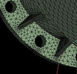
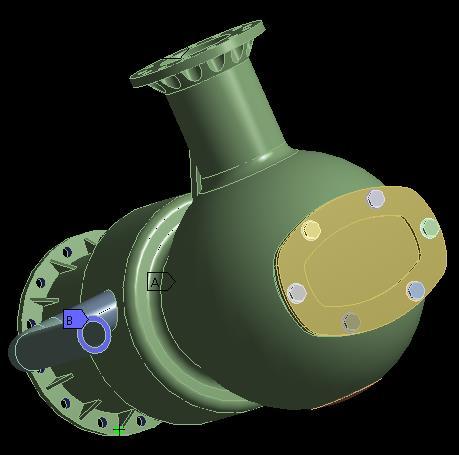
14 ... Submodeling Procedure Submodeling Example: The model shown below is initially solved using a coarse mesh. As expected we see stress concentrations in regions containing detailed geometry along with a coarse mesh. Based on these results we choose to create a submodel to explore the region circled in more detail ANSYS, Inc. February 27, 2015

15 ... Submodeling Procedure Although there are numerous geometry modeling techniques that can be used to create the submodel, we have chosen to slice a body from the full model using the DesignModeler application. This new body is our submodel and a more refined mesh is created in the Mechanical application ANSYS, Inc. February 27, 2015


16 ... Submodeling Procedure The submodel schematic is set up as shown here: Original Full Model Since the full model and submodel are comprised of different geometry, we can t simply drag and drop a new structural system on to the existing one as this would link the geometry. Instead we create a new stand alone system and drag the full model solution onto the submodel s setup cell ANSYS, Inc. February 27, 2015


17 ... Submodeling Procedure After opening the new (submodel) system open in Mechanical we can see a new Submodeling branch has automatically been inserted in the tree. If we RMB we can choose the type of result to import (displacement in this example). In the details of the imported load we choose scope to which the loads are applied. The scope here is the cut boundaries of the submodel. Note, there are numerous mapping options available when transferring loads not all of which will apply to submodeling. For a complete discussion see the section of the documentation covering External Data Import ANSYS, Inc. February 27, 2015


18 ... Submodeling Procedure RMB to import the load from the full model. When completed, the import can be reviewed graphically. Add any additional boundary conditions to the submodel to match those on the full model and solve ANSYS, Inc. February 27, 2015


19 ... Submodeling Procedure To insure that the cut boundary is far enough from the high stress region a check should be performed to compare full and submodel results near the cut boundary. Full Model Here an array of probes is used but path plots, surface plots, etc. are options as well. We simply want to verify that the results near the cut boundary are not drastically different between the full and sub models. If they are, it is usually an indication that the boundary needs to be moved further from the high stress region ANSYS, Inc. February 27, 2015 Submodel

20 Workshop Appendix B Workshop Appendix B - Submodelling ANSYS, Inc. February 27, 2015
Workshop 11.1 Meshing Evaluation
 Workshop 11.1 Meshing Evaluation 16.0 Release Introduction to ANSYS Mechanical 1 2015 ANSYS, Inc. February 27, 2015 Goals In this workshop an arm from a mechanism will be solved using several different
Example Plate with a hole
 Course in ANSYS Example Plate with a hole A Objective: Determine the maximum stress in the x-direction for point A and display the deformation figure Tasks: Create a submodel to increase the accuracy of
Workshop 3.1 2D Gear and Rack Analysis
 Workshop 3.1 2D Gear and Rack Analysis 16.0 Release Introduction to ANSYS Mechanical 1 2015 ANSYS, Inc. February 27, 2015 Assumptions Workshop 3.1 consists of a 2 part assembly representing spur and rack
Lecture 3 : General Preprocessing. Introduction to ANSYS Mechanical Release ANSYS, Inc. February 27, 2015
 Lecture 3 : General Preprocessing 16.0 Release Introduction to ANSYS Mechanical 1 2015 ANSYS, Inc. February 27, 2015 Chapter Overview In this chapter we cover basic preprocessing operations that are common
Solving Large Complex Problems. Efficient and Smart Solutions for Large Models
 Solving Large Complex Problems Efficient and Smart Solutions for Large Models 1 ANSYS Structural Mechanics Solutions offers several techniques 2 Current trends in simulation show an increased need for
Exercise 1. 3-Point Bending Using the Static Structural Module of. Ansys Workbench 14.0
 Exercise 1 3-Point Bending Using the Static Structural Module of Contents Ansys Workbench 14.0 Learn how to...1 Given...2 Questions...2 Taking advantage of symmetries...2 A. Getting started...3 A.1 Choose
Finite Element Analysis using ANSYS Mechanical APDL & ANSYS Workbench
 Finite Element Analysis using ANSYS Mechanical APDL & ANSYS Workbench Course Curriculum (Duration: 120 Hrs.) Section I: ANSYS Mechanical APDL Chapter 1: Before you start using ANSYS a. Introduction to
ANSYS - Workbench Overview. From zero to results. AGH 2014 April, 2014 W0-1
 ANSYS - Workbench Overview From zero to results 2014 W0-1 Runing ANSYS WEiP ANSYS We are going to work in most advanced ANSYS Workbench W0-2 ANSYS Workbench WEiP What is Workbench? Platform for integration
SOLIDWORKS Simulation
 SOLIDWORKS Simulation Length: 3 days Prerequisite: SOLIDWORKS Essentials Description: SOLIDWORKS Simulation is designed to make SOLIDWORKS users more productive with the SOLIDWORKS Simulation Bundle. This
ANSYS Workbench Guide
 ANSYS Workbench Guide Introduction This document serves as a step-by-step guide for conducting a Finite Element Analysis (FEA) using ANSYS Workbench. It will cover the use of the simulation package through
Introduction to ANSYS Mechanical
 Workshop 4.2 Meshing Control 15.0 Release Introduction to ANSYS Mechanical 1 2014 ANSYS, Inc. February 12, 2014 Goals Use the various ANSYS Mechanical mesh controls to enhance the mesh for the model below.
WORKSHOP 6.3 WELD FATIGUE USING NOMINAL STRESS METHOD. For ANSYS release 14
 WORKSHOP 6.3 WELD FATIGUE USING NOMINAL STRESS METHOD For ANSYS release 14 Objective: In this workshop, a weld fatigue analysis on a VKR-beam with a plate on top using the nominal stress method is demonstrated.
ES 230 Strengths Intro to Finite Element Modeling & Analysis Homework Assignment 2
 ES 230 Strengths Intro to Finite Element Modeling & Analysis Homework Assignment 2 In this homework assignment you will use your rapidly developing ANSYS skill set to model and analyze three different
EMAG Tutorial 4: 3 Phase Transformer
 EMAG Tutorial 4: 3 Phase Transformer Tutorial 4 ANSYS, Inc. Proprietary Inventory #003000 1-1 Start Workbench Workbench-Si imulation Dynamics 1-2 The Project Page Loads Hold down LMB to drag Geometry into
Lecture 5 Modeling Connections
 Lecture 5 Modeling Connections 16.0 Release Introduction to ANSYS Mechanical 1 2015 ANSYS, Inc. February 27, 2015 Chapter Overview In this chapter, we will extend the discussion of contact control begun
Solving FSI Applications Using ANSYS Mechanical and ANSYS Fluent
 Workshop Transient 1-way FSI Load Mapping using ACT Extension 15. 0 Release Solving FSI Applications Using ANSYS Mechanical and ANSYS Fluent 1 2014 ANSYS, Inc. Workshop Description: This example considers
Introduction to ANSYS Mechanical
 Lecture 6 Modeling Connections 15.0 Release Introduction to ANSYS Mechanical 1 2012 ANSYS, Inc. February 12, 2014 Chapter Overview In this chapter, we will extend the discussion of contact control begun
COMPUTER AIDED ENGINEERING. Part-1
 COMPUTER AIDED ENGINEERING Course no. 7962 Finite Element Modelling and Simulation Finite Element Modelling and Simulation Part-1 Modeling & Simulation System A system exists and operates in time and space.
Aufgabe 1: Dreipunktbiegung mit ANSYS Workbench
 Aufgabe 1: Dreipunktbiegung mit ANSYS Workbench Contents Beam under 3-Pt Bending [Balken unter 3-Pkt-Biegung]... 2 Taking advantage of symmetries... 3 Starting and Configuring ANSYS Workbench... 4 A. Pre-Processing:
Lecture 7: Mesh Quality & Advanced Topics. Introduction to ANSYS Meshing Release ANSYS, Inc. February 12, 2015
 Lecture 7: Mesh Quality & Advanced Topics 15.0 Release Introduction to ANSYS Meshing 1 2015 ANSYS, Inc. February 12, 2015 Overview In this lecture we will learn: Impact of the Mesh Quality on the Solution
Workshop 4.2 : Mesh Control
 Workshop 4.2 : Mesh Control 16.0 Release Introduction to ANSYS Mechanical 1 2015 ANSYS, Inc. February 27, 2015 Goals Use the various ANSYS Mechanical mesh controls to enhance the mesh for the model below.
ACP (ANSYS Composite Prep/Post) Jim Kosloski
 Jim Kosloski") ACP (ANSYS Composite Prep/Post) Jim Kosloski ACP Background ANSYS Composite PrepPost is an add-on module dedicated to the modeling of layered composite structures. ACP is now included with the Mechanical
ACP (ANSYS Composite Prep/Post) Jim Kosloski ACP Background ANSYS Composite PrepPost is an add-on module dedicated to the modeling of layered composite structures. ACP is now included with the Mechanical
PTC Newsletter January 14th, 2002
 PTC Email Newsletter January 14th, 2002 PTC Product Focus: Pro/MECHANICA (Structure) Tip of the Week: Creating and using Rigid Connections Upcoming Events and Training Class Schedules PTC Product Focus:
Visit the following websites to learn more about this book:
 Visit the following websites to learn more about this book: 6 Introduction to Finite Element Simulation Historically, finite element modeling tools were only capable of solving the simplest engineering
Introduction to ANSYS LS-DYNA
 Lecture 12 Introduction to ANSYS LS-DYNA Extension 14.5 Release Introduction to ANSYS LS-DYNA 2012 ANSYS, Inc. November 8, 2012 1 Release 14.5 What is ANSYS LS-DYNA Extension ANSYS LS-DYNA in Workbench
Appendix: To be performed during the lab session
 Appendix: To be performed during the lab session Flow over a Cylinder Two Dimensional Case Using ANSYS Workbench Simple Mesh Latest revision: September 18, 2014 The primary objective of this Tutorial is
ANSYS AIM Tutorial Structural Analysis of a Plate with Hole
 ANSYS AIM Tutorial Structural Analysis of a Plate with Hole Author(s): Sebastian Vecchi, ANSYS Created using ANSYS AIM 18.1 Problem Specification Pre-Analysis & Start Up Analytical vs. Numerical Approaches
Nastran In-CAD: Understanding Data Conversion, Data Type, and Contour Type
 Nastran In-CAD: Understanding,, and Issue When creating a contour plot of a result, what is meant by " ", " ", and " "? The options in the drop-downs are as follows: 1. : "Average", "Maximum", or "Minimum"
Exercise 1: 3-Pt Bending using ANSYS Workbench
 Exercise 1: 3-Pt Bending using ANSYS Workbench Contents Starting and Configuring ANSYS Workbench... 2 1. Starting Windows on the MAC... 2 2. Login into Windows... 2 3. Start ANSYS Workbench... 2 4. Configuring
Finite Element Course ANSYS Mechanical Tutorial Tutorial 4 Plate With a Hole
 Problem Specification Finite Element Course ANSYS Mechanical Tutorial Tutorial 4 Plate With a Hole Consider the classic example of a circular hole in a rectangular plate of constant thickness. The plate
ANSYS Mechanical Basic Structural Nonlinearities
 Workshop 4A Metal Plasticity 14. 0 Release ANSYS Mechanical Basic Structural Nonlinearities 1 Goal: Workshop 4A Metal Plasticity Define a nonlinear metal plasticity material for a belleville spring geometry
Abaqus/CAE Axisymmetric Tutorial (Version 2016)
") Abaqus/CAE Axisymmetric Tutorial (Version 2016) Problem Description A round bar with tapered diameter has a total load of 1000 N applied to its top face. The bottom of the bar is completely fixed. Determine
Abaqus/CAE Axisymmetric Tutorial (Version 2016) Problem Description A round bar with tapered diameter has a total load of 1000 N applied to its top face. The bottom of the bar is completely fixed. Determine
Parametric. Practices. Patrick Cunningham. CAE Associates Inc. and ANSYS Inc. Proprietary 2012 CAE Associates Inc. and ANSYS Inc. All rights reserved.
 Parametric Modeling Best Practices Patrick Cunningham July, 2012 CAE Associates Inc. and ANSYS Inc. Proprietary 2012 CAE Associates Inc. and ANSYS Inc. All rights reserved. E-Learning Webinar Series This
Workbench-Mechanical Structural Nonlinearities
 Workshop 2B Assembly Contact Workbench-Mechanical Structural Nonlinearities WS2B-1 Workshop 2B Assembly Contact Goal: In this workshop our goal is to investigate the behavior of the pipe clamp assembly
Chapter 6. Concept Modeling. ANSYS, Inc. Proprietary Inventory # May 11, ANSYS, Inc. All rights reserved.
 Chapter 6 Concept Modeling 6-1 Contents Concept Modeling Creating Line Bodies Modifying i Line Bodies Cross Sections Cross Section Alignment Cross Section Offset Surfaces From Lines Surfaces From Sketches
ASME Fatigue DOCUMENTATION. ANSYS Mechanical Application. Extension version Compatible ANSYS version
 ASME Fatigue ANSYS Mechanical Application DOCUMENTATION Extension version 180.1 Release date 06-Apr-17 Compatible ANSYS version 18.0 www.edrmedeso.com Table of Contents 1 INTRODUCTION... 3 2 PRODUCT RESTRICTIONS...
Similar Pulley Wheel Description J.E. Akin, Rice University
 Similar Pulley Wheel Description J.E. Akin, Rice University The SolidWorks simulation tutorial on the analysis of an assembly suggested noting another type of boundary condition that is not illustrated
Global to Local Model Interface for Deepwater Top Tension Risers
 Global to Local Model Interface for Deepwater Top Tension Risers Mateusz Podskarbi Karan Kakar 2H Offshore Inc, Houston, TX Abstract The water depths from which oil and gas are being produced are reaching
Appendix B: Creating and Analyzing a Simple Model in Abaqus/CAE
 Getting Started with Abaqus: Interactive Edition Appendix B: Creating and Analyzing a Simple Model in Abaqus/CAE The following section is a basic tutorial for the experienced Abaqus user. It leads you
ANSYS. DesignXplorer - Design for Six Sigma. Crane Hook
 ANSYS DesignXplorer - Crane Hook Purpose Using the crane hook model at right we will demonstrate how the design for six sigma results can be used in DesignXplorer 8.1 Goal Our first goal is to verify that
ANSYS AIM 16.0 Overview. AIM Program Management
 1 2015 ANSYS, Inc. September 27, 2015 ANSYS AIM 16.0 Overview AIM Program Management 2 2015 ANSYS, Inc. September 27, 2015 Today s Simulation Challenges Leveraging simulation across engineering organizations
Stump the WBE Wizard. Mallett Technology Year End Meeting December 19,
 Stump the WBE Wizard 1 How do you become an AWE Wizard? Rich Alferi, Respironics: Since I have been using WB for a while, I think I have had most of my questions answered through tech support and training
Customer Training Material. Contact Control. Mechanical. ANSYS, Inc. Proprietary 2010 ANSYS, Inc. All rights reserved. WS3.1-1
 Workshop 3.1 Contact Control Introduction to ANSYS Mechanical WS3.1-1 Goals Workshop 3.1 investigates contact behavior on a simple assembly. It is meant to illustrate how rigid body motion can occur as
Tutorial Week 4 Biomedical Modelling in Ansys Workbench (The Complete Guide with Anatomy and Implant)
") Tutorial Week 4 Biomedical Modelling in Ansys Workbench (The Complete Guide with Anatomy and Implant) Step 1: Create the Anatomical Model in ScanIP Import the DICOM files for the Proximal Femur dataset
Tutorial Week 4 Biomedical Modelling in Ansys Workbench (The Complete Guide with Anatomy and Implant) Step 1: Create the Anatomical Model in ScanIP Import the DICOM files for the Proximal Femur dataset
equivalent stress to the yield stess.
 Example 10.2-1 [Ansys Workbench/Thermal Stress and User Defined Result] A 50m long deck sitting on superstructures that sit on top of substructures is modeled by a box shape of size 20 x 5 x 50 m 3. It
ANSYS AIM Tutorial Thermal Stresses in a Bar
 ANSYS AIM Tutorial Thermal Stresses in a Bar Author(s): Sebastian Vecchi, ANSYS Created using ANSYS AIM 18.1 Problem Specification Pre-Analysis & Start Up Pre-Analysis Start-Up Geometry Draw Geometry Create
Finite Element Course ANSYS Mechanical Tutorial Tutorial 3 Cantilever Beam
 Problem Specification Finite Element Course ANSYS Mechanical Tutorial Tutorial 3 Cantilever Beam Consider the beam in the figure below. It is clamped on the left side and has a point force of 8kN acting
Steady-State and Transient Thermal Analysis of a Circuit Board
 Steady-State and Transient Thermal Analysis of a Circuit Board Problem Description The circuit board shown below includes three chips that produce heat during normal operation. One chip stays energized
A B C D E. Settings Choose height, H, free stream velocity, U, and fluid (dynamic viscosity and density ) so that: Reynolds number
 so that: Reynolds number") Individual task Objective To derive the drag coefficient for a 2D object, defined as where D (N/m) is the aerodynamic drag force (per unit length in the third direction) acting on the object. The object
Individual task Objective To derive the drag coefficient for a 2D object, defined as where D (N/m) is the aerodynamic drag force (per unit length in the third direction) acting on the object. The object
BioIRC solutions. CFDVasc manual
 BioIRC solutions CFDVasc manual Main window of application is consisted from two parts: toolbar - which consist set of button for accessing variety of present functionalities image area area in which is
Effectiveness of Element Free Galerkin Method over FEM
 Effectiveness of Element Free Galerkin Method over FEM Remya C R 1, Suji P 2 1 M Tech Student, Dept. of Civil Engineering, Sri Vellappaly Natesan College of Engineering, Pallickal P O, Mavelikara, Kerala,
SOLIDWORKS Simulation Avoiding Singularities
 SOLIDWORKS Simulation Avoiding Singularities What is a Singularity? A singularity is a function s divergence into infinity. SOLIDWORKS Simulation occasionally produces stress (or heat flux) singularities.
Odysseas Skartsis ENGN2340. Project LEFM Convergence Study 12/11/13
 Odysseas Skartsis ENGN2340 Project LEFM Convergence Study 2//3 Thanks to Tianyang Zhang, Davide Grazioli, and Ruike Zhao for their helpful tips on using ABAQUS. Structure of this report Main body: Appendix:
Ansys Mechanical APDL
 Ansys Mechanical APDL Day 1: FEA and ANSYS 9.00 12.00 About ANSYS, What is FEA?, Instructor Example Getting Started 12.00 1.00 Interactive Vs. Batch Mode, Starting ANSYS, Product Launcher, ANSYS Workbench,
Exercise 2: Mesh Resolution, Element Shapes, Basis Functions & Convergence Analyses
 Exercise 2: Mesh Resolution, Element Shapes, Basis Functions & Convergence Analyses Goals In this exercise, we will explore the strengths and weaknesses of different element types (tetrahedrons vs. hexahedrons,
ME 442. Marc/Mentat-2011 Tutorial-1
 ME 442 Overview Marc/Mentat-2011 Tutorial-1 The purpose of this tutorial is to introduce the new user to the MSC/MARC/MENTAT finite element program. It should take about one hour to complete. The MARC/MENTAT
WORKSHOP 6.4 WELD FATIGUE USING HOT SPOT STRESS METHOD. For ANSYS release 14
 WORKSHOP 6.4 WELD FATIGUE USING HOT SPOT STRESS METHOD For ANSYS release 14 Objective: In this workshop, a weld fatigue analysis on a VKR-beam with a plate on top using the nominal stress method is demonstrated.
C-clamp FEA Analysis
 C-clamp FEA Analysis ME 341 students are asked to determine the stresses on the inner and outer surface of a C-clamp at a point on the curved section and the straight section of the clamp. The following
2008 International ANSYS Conference
 2008 International ANSYS Conference FEM AND FSI SIMULATIONS OF IMPACT LOADS ON GRP SUBSEA COMPOSITE COVERS Kjetil Rognlien, MSc Technical Consultant EDR AS, Norway 2008 ANSYS, Inc. All rights reserved.
Structural Mechanics With ANSYS Pierre THIEFFRY Lead Product Manager ANSYS, Inc.
 Structural Mechanics With ANSYS Pierre THIEFFRY Lead Product Manager ANSYS, Inc. 1 ANSYS Structural Mechanics provides highend solver solutions within a highly productive user environment to reliably and
GTS. midas GTS Advanced Webinar. Date: June 5, 2012 Topic: General Use of midas GTS (Part II) Presenter: Vipul Kumar
 Presenter: Vipul Kumar") midas GTS Advanced Webinar Date: June 5, 2012 Topic: General Use of midas GTS (Part II) Presenter: Vipul Kumar Bridging Your Innovations to Realities GTS MIDAS Information Technology Co., Ltd. [1/30] Contents:
midas GTS Advanced Webinar Date: June 5, 2012 Topic: General Use of midas GTS (Part II) Presenter: Vipul Kumar Bridging Your Innovations to Realities GTS MIDAS Information Technology Co., Ltd. [1/30] Contents:
TryItNow! Step by Step Walkthrough: Spoiler Support
 TryItNow! Step by Step Walkthrough: Spoiler Support 1 2015 ANSYS, Inc. March 28, 2016 TryItNow! Step by Step Walkthrough: Spoiler Support ANSYS designed this TryItNow! experience to give you quick access
Creating and Analyzing a Simple Model in Abaqus/CAE
 Appendix B: Creating and Analyzing a Simple Model in Abaqus/CAE The following section is a basic tutorial for the experienced Abaqus user. It leads you through the Abaqus/CAE modeling process by visiting
Abaqus CAE Tutorial 6: Contact Problem
 ENGI 7706/7934: Finite Element Analysis Abaqus CAE Tutorial 6: Contact Problem Problem Description In this problem, a segment of an electrical contact switch (steel) is modeled by displacing the upper
USAGE OF ANSA S AUTOMATED VOLUME MESHING-METHODS IN THE RAPID PRODUCT DEVELOPMENT PROCESS OF DIESEL ENGINES
 USAGE OF ANSA S AUTOMATED VOLUME MESHING-METHODS IN THE RAPID PRODUCT DEVELOPMENT PROCESS OF DIESEL ENGINES Günther Pessl *, Dr. Robert Ehart, Gerwin Bumberger BMW Motoren GmbH, Austria KEYWORDS - ANSA,
Workbench Tutorial Flow Over an Airfoil, Page 1 ANSYS Workbench Tutorial Flow Over an Airfoil
 Workbench Tutorial Flow Over an Airfoil, Page 1 ANSYS Workbench Tutorial Flow Over an Airfoil Authors: Scott Richards, Keith Martin, and John M. Cimbala, Penn State University Latest revision: 17 January
Shape optimisation using breakthrough technologies
 Shape optimisation using breakthrough technologies Compiled by Mike Slack Ansys Technical Services 2010 ANSYS, Inc. All rights reserved. 1 ANSYS, Inc. Proprietary Introduction Shape optimisation technologies
MAE Advanced Computer Aided Design. 02. Ansys Workbench Doc 01. Introduction to Ansys Workbench
 MAE 656 - Advanced Computer Aided Design 02. Ansys Workbench Doc 01 Introduction to Ansys Workbench Main Screen Components: Top menu Toolbox Messages Progress Project Properties Top Menu File Top Menu
Revised Sheet Metal Simulation, J.E. Akin, Rice University
 Revised Sheet Metal Simulation, J.E. Akin, Rice University A SolidWorks simulation tutorial is just intended to illustrate where to find various icons that you would need in a real engineering analysis.
Appendix R. ESATAN Thermal Modelling Suite Product Developments. Chris Kirtley (ITP Engines UK, United Kingdom)
") 211 Appendix R ESATAN Suite Product Developments Chris Kirtley (ITP Engines UK, United Kingdom) 31 st European Space Workshop 24 25 October 2017 212 ESATAN Suite Product Developments Abstract A major focus
211 Appendix R ESATAN Suite Product Developments Chris Kirtley (ITP Engines UK, United Kingdom) 31 st European Space Workshop 24 25 October 2017 212 ESATAN Suite Product Developments Abstract A major focus
R15.0 Structural Update
 R15.0 Structural Update 1 Tim Pawlak R&D Fellow ANSYS Structural Update Topics Geometry and Mesh Material Behavior Numerical Methods Composites Dynamics Submodeling Multiphysics Solvers User Interface
ANSYS 5.6 Tutorials Lecture # 2 - Static Structural Analysis
 R50 ANSYS 5.6 Tutorials Lecture # 2 - Static Structural Analysis Example 1 Static Analysis of a Bracket 1. Problem Description: The objective of the problem is to demonstrate the basic ANSYS procedures
ANSYS Element. elearning. Peter Barrett October CAE Associates Inc. and ANSYS Inc. All rights reserved.
 ANSYS Element Selection elearning Peter Barrett October 2012 2012 CAE Associates Inc. and ANSYS Inc. All rights reserved. ANSYS Element Selection What is the best element type(s) for my analysis? Best
Essay 5 Tutorial for a Three-Dimensional Heat Conduction Problem Using ANSYS
 Essay 5 Tutorial for a Three-Dimensional Heat Conduction Problem Using ANSYS 5.1 Introduction The problem selected to illustrate the use of ANSYS software for a three-dimensional steadystate heat conduction
Import a CAD Model 2018
 Import a CAD Model 2018 Import CAD Model In this tutorial you will import a CAD file, then add a 500 kw burner fire. Figure 1. Burner fire in this example This tutorial demonstrates how to: Import a CAD
Introduction to ANSYS DesignModeler
 Lecture 9 Beams and Shells 14. 5 Release Introduction to ANSYS DesignModeler 2012 ANSYS, Inc. November 20, 2012 1 Release 14.5 Beams & Shells The features in the Concept menu are used to create and modify
PTC Creo Simulate. Features and Specifications. Data Sheet
 PTC Creo Simulate PTC Creo Simulate gives designers and engineers the power to evaluate structural and thermal product performance on your digital model before resorting to costly, time-consuming physical
CHAPTER 4. Numerical Models. descriptions of the boundary conditions, element types, validation, and the force
 CHAPTER 4 Numerical Models This chapter presents the development of numerical models for sandwich beams/plates subjected to four-point bending and the hydromat test system. Detailed descriptions of the
Introduction to ANSYS DesignXplorer
 Overview 14. 5 Release Introduction to ANSYS DesignXplorer 1 2013 ANSYS, Inc. September 27, 2013 What is DesignXplorer? DesignXplorer (DX) is a tool that uses response surfaces and direct optimization
TRINITAS. a Finite Element stand-alone tool for Conceptual design, Optimization and General finite element analysis. Introductional Manual
 TRINITAS a Finite Element stand-alone tool for Conceptual design, Optimization and General finite element analysis Introductional Manual Bo Torstenfelt Contents 1 Introduction 1 2 Starting the Program
Stress analysis of toroidal shell
 Stress analysis of toroidal shell Cristian PURDEL*, Marcel STERE** *Corresponding author Department of Aerospace Structures INCAS - National Institute for Aerospace Research Elie Carafoli Bdul Iuliu Maniu
CAD - How Computer Can Aid Design?
 CAD - How Computer Can Aid Design? Automating Drawing Generation Creating an Accurate 3D Model to Better Represent the Design and Allowing Easy Design Improvements Evaluating How Good is the Design and
Introduction to CFX. Workshop 2. Transonic Flow Over a NACA 0012 Airfoil. WS2-1. ANSYS, Inc. Proprietary 2009 ANSYS, Inc. All rights reserved.
 Workshop 2 Transonic Flow Over a NACA 0012 Airfoil. Introduction to CFX WS2-1 Goals The purpose of this tutorial is to introduce the user to modelling flow in high speed external aerodynamic applications.
Multi-Axis Tabular Loads in ANSYS Workbench
 Multi-Axis Tabular Loads in ANSYS Workbench 2/24/2017 1 Users of ANSYS Workbench (18) may have noticed that the they have a choice of independent variables when defining a tabular load Typical choices
Report Generation. Name: Path: Keywords:
 Report Generation Name: Path: Keywords: ReportGeneration/repgen /Examples//ReportGeneration/repgen analys: eigen geomet nonlin physic. constr: suppor. elemen: beam class2 curved interf l13be q20sh q24if
An Explanation on Computation of Fracture Mechanics Parameters in ANSYS
 University of Tennessee Space Institute Department of Mechanical, Aerospace & Biomedical Engineering Fracture Mechanics Course (ME 524) An Explanation on Computation of Fracture Mechanics Parameters in
Chapter 5 Modeling and Simulation of Mechanism
 Chapter 5 Modeling and Simulation of Mechanism In the present study, KED analysis of four bar planar mechanism using MATLAB program and ANSYS software has been carried out. The analysis has also been carried
Appendix A: Mesh Nonlinear Adaptivity. ANSYS Mechanical Introduction to Structural Nonlinearities
 Appendix A: Mesh Nonlinear Adaptivity 16.0 Release ANSYS Mechanical Introduction to Structural Nonlinearities 1 2015 ANSYS, Inc. Mesh Nonlinear Adaptivity Introduction to Mesh Nonlinear Adaptivity Understanding
Lab#5 Combined analysis types in ANSYS By C. Daley
 Engineering 5003 - Ship Structures I Lab#5 Combined analysis types in ANSYS By C. Daley Overview In this lab we will model a simple pinned column using shell elements. Once again, we will use SpaceClaim
MAE 323: Lab 7. Instructions. Pressure Vessel Alex Grishin MAE 323 Lab Instructions 1
 Instructions MAE 323 Lab Instructions 1 Problem Definition Determine how different element types perform for modeling a cylindrical pressure vessel over a wide range of r/t ratios, and how the hoop stress
Basic Exercises Maxwell Link with ANSYS Mechanical. Link between ANSYS Maxwell 3D and ANSYS Mechanical
 Link between ANSYS Maxwell 3D and ANSYS Mechanical This exercise describes how to set up a Maxwell 3D Eddy Current project and then link the losses to ANSYS Mechanical for a thermal calculation 3D Geometry:
EN1740 Computer Aided Visualization and Design Spring /26/2012 Brian C. P. Burke
 EN1740 Computer Aided Visualization and Design Spring 2012 4/26/2012 Brian C. P. Burke Last time: More motion analysis with Pro/E Tonight: Introduction to external analysis products ABAQUS External Analysis
ANSYS AIM Tutorial Compressible Flow in a Nozzle
 ANSYS AIM Tutorial Compressible Flow in a Nozzle Author(s): Sebastian Vecchi Created using ANSYS AIM 18.1 Problem Specification Pre-Analysis & Start Up Pre-Analysis Start-Up Geometry Import Geometry Mesh
CE Advanced Structural Analysis. Lab 4 SAP2000 Plane Elasticity
 Department of Civil & Geological Engineering COLLEGE OF ENGINEERING CE 463.3 Advanced Structural Analysis Lab 4 SAP2000 Plane Elasticity February 27 th, 2013 T.A: Ouafi Saha Professor: M. Boulfiza 1. Rectangular
OzenCloud Case Studies
 OzenCloud Case Studies Case Studies, April 20, 2015 ANSYS in the Cloud Case Studies: Aerodynamics & fluttering study on an aircraft wing using fluid structure interaction 1 Powered by UberCloud http://www.theubercloud.com
FRANC3D / OSM Tutorial Slides
 FRANC3D / OSM Tutorial Slides October, 2003 Cornell Fracture Group Tutorial Example Hands-on-training learn how to use OSM to build simple models learn how to do uncracked stress analysis using FRANC3D
SETTLEMENT OF A CIRCULAR FOOTING ON SAND
 1 SETTLEMENT OF A CIRCULAR FOOTING ON SAND In this chapter a first application is considered, namely the settlement of a circular foundation footing on sand. This is the first step in becoming familiar
Exercise 1: Axle Structural Static Analysis
 Exercise 1: Axle Structural Static Analysis The purpose of this exercise is to cover the basic functionality of the Mechanical Toolbar (MTB) in the context of performing an actual analysis. Details of
Tutorial 3. Correlated Random Hydraulic Conductivity Field
 Tutorial 3 Correlated Random Hydraulic Conductivity Field Table of Contents Objective. 1 Step-by-Step Procedure... 2 Section 1 Generation of Correlated Random Hydraulic Conductivity Field 2 Step 1: Open
Elastic Analysis of a Deep Beam with Web Opening
 Elastic Analysis of a Deep Beam with Web Opening Outline 1 Description 2 Finite Element Model 2.1 Units 2.2 Geometry definition 2.3 Properties 2.4 Boundary conditions 2.4.1 Constraints 2.4.2 Vertical load