ANSYS FLUENT. Airfoil Analysis and Tutorial
|
|
|
- Clarence Miller
- 5 years ago
- Views:
Transcription
1 ANSYS FLUENT Airfoil Analysis and Tutorial ENGR083: Fluid Mechanics II Terry Yu 5/11/2017
2 Abstract The NACA 0012 airfoil was one of the earliest airfoils created. Its mathematically simple shape and age have meant that it is one of the first choices for validating CFD programs, as there is a wealth of data on this particular airfoil. Though the NACA 0012 airfoil is not in general use currently due to its relatively poor lift to drag ratio, it remains a useful research tool. It still sees some use, however, in control surfaces and helicopter blades, as it is symmetric and thus has a simple correlation between angle of attack and lift. This project validated methods for using ANSYS Fluent and created a tutorial for future E83 students to also analyze this airfoil. The resulting coefficient of lift plot is remarkably similar to one produced by NASA s Langley Center, while the coefficient of drag plot seems to be in error. This is likely due to our simple viscosity model. Introduction ANSYS Fluent is part of the ANSYS suite of engineering analysis software, which includes Mechanical APDL, BladeGen, and many other software packages capable of thermal analysis, electromagnetic analysis, and more. Fluent is also widely recognized as one of the industry standard CFD software packages. Although Solidworks is capable of performing rudimentary CFD analysis, it is only a rudimentary approach as Solidworks is fundamentally CAD software and is not built with simulation in mind, as ANSYS is. The versatility and capability of ANSYS Fluent makes it an easy first choice for fluid dynamics analysis. This project seeks to find a basic understanding of ANSYS Fluent and develop a tutorial for future students to also learn from this software. In a previous project, I analyzed the NACA 0012 airfoil structurally to understand its deflection due to aerodynamic forces in a helicopter. Thus, I had the model readily available. However, the model was in 3D form, and I had to analyze only a cross section of the airfoil. Unfortunately, Fluent s academic license does not allow for enough meshes to cover the entire 3D airfoil. This was fortuitous, though, as we were able to corroborate our results with a NASA Langley Center study on the characteristics of the airfoil. After completing our analysis, we created a tutorial to introduce new E83 students to Fluent. This tutorial will walk the user through importing the airfoil model and setting up the boundary conditions for meshing and solving the fluids problem. Due to time, we were unable to implement a tutorial for modeling or for more simple shapes in Fluent, which may have been more helpful to novice students.

3 Problem The fundamental problem we are attempting to solve is the modeling of a 2D airfoil cross section. Given the below figure, how can we determine the lift and drag acting on the airfoil? The picture above shows a box with an airfoil cutout. In order to analyze an airfoil, my implementation does not implement a wind tunnel and an object suspended in it, although that is a valid approach. Instead, this procedure cuts out an airfoil shape from a bounding box, and meshes the box. The entire box is then divided into finite elements, and the fluid dynamics equations are solved. By examining the fluid properties near the airfoil cutout, the lift and drag can be determined. We have wind tunnel tests and other software validations from the Langley center, so we are able to compare our lift and drag results to validated results, and see if there were any mistakes in our protocol or software implementation. For our airfoil, we are working in the turbulent regime, with Re = 6million. Our speed is M=0.15, which converts to about 51 m/s. This region is essentially incompressible, but the NASA website cautions against running incompressible flow, as the results may differ. From determined lift and drag forces, we can calculate the lift and drag coefficients. These are plotted against the angle of attack, and compared to available data. A close match confirms that our implementation and procedure are correct.
4 Theory First, we must determine the regime that our analysis is in. Our reference data is for Re = 6 million, which is far into the turbulent region. Re = ρvl μ where ρ=density, v=velocity, μ=dynamic viscosity, and L is the characteristic length, which for our airfoil is the chord. With known viscosity, density, and speed, we can calculate the length. The values we used were: ρ = kg m 3 v = 51 m s μ = x 10 5 kg m s L = m To determine the coefficients of drag and lift, we use the following equations from the NASA website 1. where L and D are the lift and drag, ρ ref is the free stream density, U ref is the free stream velocity, and A is the reference area (in 2-D it is reference length, or area per unit span). It should be noted that these differ from the equations derived in class. Our solver has the energy equation enabled, which enables compressible flow. To model compressible flow, we use the ideal gas law to determine the density at any given point. 1

5 Fluent models turbulence with the Reynolds average Navier-Stokes Equations (RANS). This is one of the most common approaches to computing flows. Other methods exist to model flow, such as Detached Eddy Simulation or Large Eddy simulation. However, while more accurate, RANS is far less computationally intensive and yields close enough results for the scales that we are working at. Below is the full Reynolds averaged momentum equation. At each iteration, this equation is solved for all the mesh quadrilaterals. The Reynolds stress tensor describes unknowns introduced by modeling and must be related to average flow quantities. To calculate the Reynolds stress tensor, we must use eddy viscosity models. The Boussinesq hypothesis states that Reynold stresses can be modeled with an eddy viscosity μ T. This is reasonable for simple turbulent shear flows such as boundary layers, round jets, mixing layers, channel flows, but for complex flows we need to fully solve the Reynolds Stress tensor, which is computationally intense. The eddy viscosity μ T above must be resolved to complete the RANS equations. Below are our choices of models. There are many methods of calculating eddy viscosity, and we have chosen the Spalart-Allmaras equation for its simplicity. RANS based models Eddy viscosity models
6 Spalart-Allmaras is the computationally simplest model. It is economical for large meshes, but performs poorly for 3D flows, free shear flows, and flows with strong separation. It is suitable for mildly complex (quasi-2d) external/internal flows and boundary layer flows under pressure gradient (e.g. airfoils, wings, airplane fuselages, missiles, ship hulls), which is perfect for our simulations. The other equations are more suitable to complex flows, such as turbomachinery, flows with high separation, flows with high strain rates, or flows with high swirl rates. The Spalart-Allmaras equations are adequate for our purposes, but any more complex analysis than simple shapes in a uniform flow. The Spalart-Allmaras equations can be characterized as where eddy viscosity is obtained from By solving this equation, Fluent can solve for the eddy viscosity. With the eddy viscosity, the Reynolds stress tensor is known, and once the stress tensor is known, the entire Reynolds- Averaged Navier Stokes equations can be solved.
7 Results At the proscribed Re = 6 million, we obtained the following graph for the lift coefficient: This was overlaid with the NASA coefficient of lift chart. Our values are in orange. This shows very good agreement, with only some discontinuities in the stall region.
8 The coefficient of drag vs coefficient of lift graph was also plotted:
9 This was also overlaid with the NASA coefficient of lift chart. Our values are in green. This shows fairly poor agreement with the NASA values. Although we managed the same general shape, we are off by a fair amount.


10 Following are sample contours and streamlines from a 10 degree angle case.
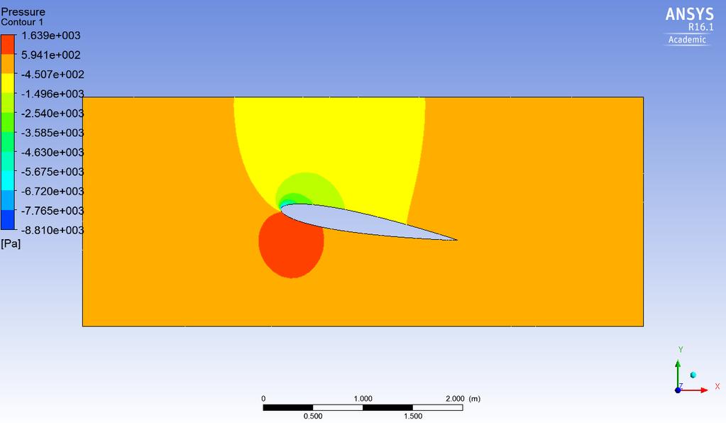
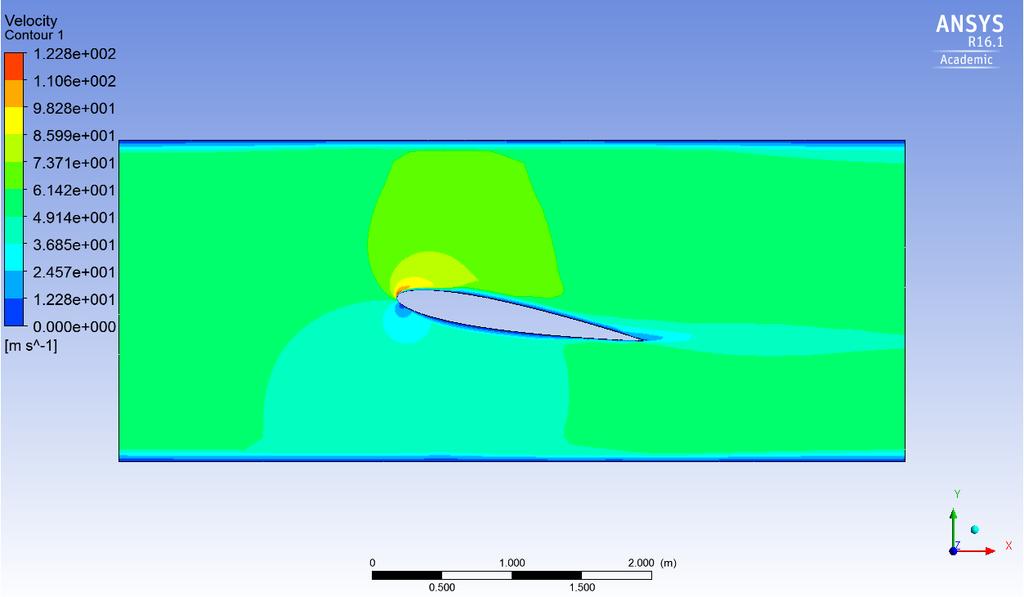
11


12 Below are some sample streamlines and contours from the 25 degree case, where the airfoil is stalled.
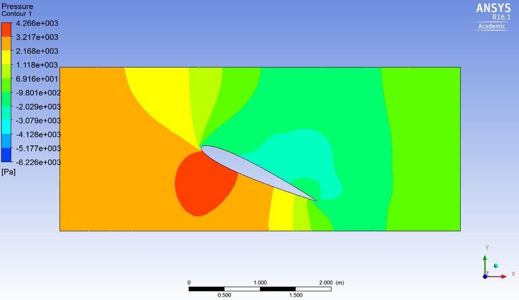
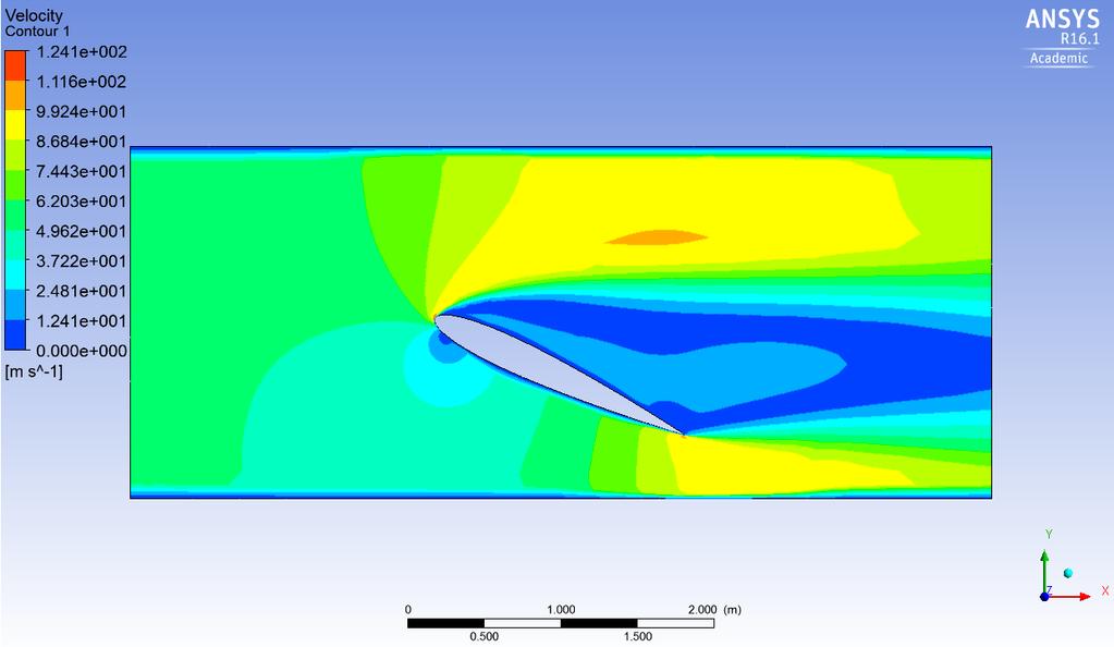
13
14 Discussion and Future Work Our model was validated for lift. It shows very close agreement to the NASA Langley Center s data, which includes wind tunnel and software testing. We have successfully modeled an airfoil s lift in ANSYS Fluent to a very high degree of accuracy. However, our drag results had some disagreements with the NASA results. Although we maintained the same overall shape, we started producing an enormous amount of drag at higher angles of attacks. A possible cause of this is the farfield boundary effect, which can have effects on lift and drag at high lift conditions. This effect is unique to compressible flows and is a quirk of numerical analysis, where boundary conditions are incorrectly set for compressible flows and the solver is not aware of the farfield equilibrium conditions for the boundaries, and leads to waves developing in the mesh. Further investigation is required into the settings necessary to correct for this in ANSYS Fluent. We have successfully developed a tutorial to complete the lift and drag analysis on an airfoil in Fluent. This tutorial starts the user at a model and walks them through configuring the fluid dynamics solver. Future work includes implementing simpler problems into the Fluent tutorial, such as flow over a flat plate or flow over a cylinder. These simulations are relatively short, so a more complex modeling scheme such as full Reynolds Stress tensor solving could be used. The bounding box could be even further extended, and farfield boundary conditions could be investigated to ensure they are not causing the drag to be erroneous. References 1. 2DN00: 2D NACA 0012 Airfoil Validation Case. NASA Langley Turbulence Modeling Resource, The Spalart-Allmaras Turbulence Model. NASA Langley Turbulence Modeling Resource, Implementing Turbulence Models into the Compressible RANS Equations Modeling Turbulent Flow tes_fluent-v pdf, ANSYS.
15 Appendix: Raw Data Aoa Lift (raw) Drag (raw) Cl Cd Aoa Lift (raw) Drag (raw) Cl Cd


16 Appendix: Fluent Tutorial This is a short tutorial in running the airfoil analysis with ANSYS Workbench with the NACA 0012 airfoil. There are four provided files, blade_only.agdb, blade_2.iges, airfoil_single_example.wbpj, and wing_analysis_aggregate.wbpj, The blade_2.iges file contains the base 3D geometry for the blade. The wing_analysis_aggregate.wbpj is simply a bunch of models with connected to a parameter set which allows for running all the angles of attacks at once. This is useful when one needs to run the entire model, but for the purposes of this tutorial we will only run one system at a time. This tutorial will focus on constructing a model from the blade_only.agdb file. Double click this file to open it. Once opened, ANSYS will likely throw an error saying that the blade_2.iges file is missing. This can be ignored for now; we will locate it later. The following screen should appear:
17 This is the home screen for ANSYS Workbench, which incorporates all the ANSYS products. From the left, double click on Fluid Flow (Fluent). A new system will appear. Drag the box labeled Geometry in the A system to the box labeled Geometry in the B system, which has the question mark. They have now been linked. The screen should now look like: The large blocks are known as systems, and incorporate all the steps necessary to simulate the model. The relevant system is labeled Fluid Flow-Fluent, as we will be working with Fluent today. 1. Geometry: This is the configuration of all the geometries necessary to define the model. 2. Mesh: This creates the mesh on which Fluent s finite volume method acts. 3. Setup: This defines the physical constants, boundary conditions, and solver method. 4. Solution: This is where the solver is initiated. 5. Results: The results of the simulation can be viewed here. 6. Parameters: Fluent will output the lift and drag values here. To start, save this project. Remember to save often! First, we will inspect the geometry and adjust the angle as needed. Double click the Geometry box in A (the master geometry) to launch the DesignModeler.

 In the details section, the angle of the blade can be adjusted. When at a satisfactory angle, click GENERATE to save the changes and create the final model.")
18 First, we will import the blade_2.iges file. First click on Import as highlighted, and then click on the source. Some ellipsis will appear. Locate the blade_2.iges file and click it to import. The modeling has been done already. To move around in the window, use the middle mouse button to rotate and CTRL+middle mouse to translate. The axes on the bottom right will reset the view when clicked. Next on the left, click on Rotate. (The subscripts are purely for naming incrementing.) In the details section, the angle of the blade can be adjusted. When at a satisfactory angle, click GENERATE to save the changes and create the final model. For this example, we will use -10 degrees. Note that negative angle here corresponds to positive lift.


19 Now, return to the ANSYS Workbench screen. If properly executed, there will be green check marks next to the Geometry label. We will now launch the Mesh by double clicking it. On the left, right click on Mesh, which should have a yellow thunderbolt as the mesh hasn t been generated yet. Go to Insert>Refinement. The yellow Geometry on the bottom right will turn yellow, which is a prompt to select a geometry. Select the geometry, which will turn green. Click on Refinement, and at the details pane in the bottom right set the refinement to 2. We next need to create the named selections so the solver has boundary conditions. Switch to edge selection at the top. Right click the left edge (the inlet) and select Create Named Selection at the bottom. Call this Inlet. Repeat this for the right edge (Outlet), the upper and bottom edges (Wall-use CTRL-click to select multiple edges before right clicking), and the cutout of the airfoil (Airfoil-again, select both top and bottom edge).


20 Click GENERATE after this is done. The mesh will now generate. To see the mesh, press Mesh on the left pane. The meshing window can be closed. Return to the ANSYS workbench screen. It is recommended that you save at this point. Right click on the Mesh box and click Update. The Mesh box should have a green checkmark. Next click Setup. This will launch Fluent.

21 On the left, under Models, turn Energy on, and set Viscous to Spalart-Allmaras. Under Materials>Fluids>Air, set the density to Ideal Gas Law. This enables compressibility. Under Boundary Conditions>Inlet, set to Velocity-Inlet. For this example use 51 m/s. Ensure Outlet is set to Pressure-Outlet. Next, we will set our output parameters. Under Parameters and Customization> Parameters> Output Parameters, click Create>Lift. Click Airfoil for wall zone on the right. Then, select Save Output Parameter, and create a new parameter called Lift. Click OK, and OK again. For drag, under Parameters and Customization> Parameters> Output Parameters, click Create>Drag. Click Airfoil for wall zone on the right. Then, select Save Output Parameter, and create a new parameter called Drag. For the parameters, the force vectors should be correct, but you can reference the Design Modeler to be sure. At this step, we can start preparing the solver. Open the Solution Tab. Under Solution Methods, set the scheme to Coupled. Under Run Calculation, set the Number to Iterations to 200, adjusting if necessary. To run the method, you can double click on Run Calculation, or go to the Workbench and right click>update on Results, which will run everything up to and including Results.


22 From Results, the contours and streamlines can be inspected. Click on Parameter Set to view the lift and drag. To make the process easier, one can define the angle of attack as a parameter. This precludes going into the modeler and changing it every time. Simply check the box next to the angle box. Then, the angle can be changed from the parameter set. The density of air used by the ideal gas model is kg m3, the chord length is m, and the perimeter of the airfoil shape is 3.665m. The airfoil_single_example.wbpj contains a project that should be the end result of these instructions.
Introduction to CFX. Workshop 2. Transonic Flow Over a NACA 0012 Airfoil. WS2-1. ANSYS, Inc. Proprietary 2009 ANSYS, Inc. All rights reserved.
 Workshop 2 Transonic Flow Over a NACA 0012 Airfoil. Introduction to CFX WS2-1 Goals The purpose of this tutorial is to introduce the user to modelling flow in high speed external aerodynamic applications.
Introduction to ANSYS CFX
 Workshop 03 Fluid flow around the NACA0012 Airfoil 16.0 Release Introduction to ANSYS CFX 2015 ANSYS, Inc. March 13, 2015 1 Release 16.0 Workshop Description: The flow simulated is an external aerodynamics
Modeling External Compressible Flow
 Tutorial 3. Modeling External Compressible Flow Introduction The purpose of this tutorial is to compute the turbulent flow past a transonic airfoil at a nonzero angle of attack. You will use the Spalart-Allmaras
Express Introductory Training in ANSYS Fluent Workshop 04 Fluid Flow Around the NACA0012 Airfoil
 Express Introductory Training in ANSYS Fluent Workshop 04 Fluid Flow Around the NACA0012 Airfoil Dimitrios Sofialidis Technical Manager, SimTec Ltd. Mechanical Engineer, PhD PRACE Autumn School 2013 -
NUMERICAL 3D TRANSONIC FLOW SIMULATION OVER A WING
 Review of the Air Force Academy No.3 (35)/2017 NUMERICAL 3D TRANSONIC FLOW SIMULATION OVER A WING Cvetelina VELKOVA Department of Technical Mechanics, Naval Academy Nikola Vaptsarov,Varna, Bulgaria (cvetelina.velkova1985@gmail.com)
Estimating Vertical Drag on Helicopter Fuselage during Hovering
 Estimating Vertical Drag on Helicopter Fuselage during Hovering A. A. Wahab * and M.Hafiz Ismail ** Aeronautical & Automotive Dept., Faculty of Mechanical Engineering, Universiti Teknologi Malaysia, 81310
Verification and Validation of Turbulent Flow around a Clark-Y Airfoil
 1 Verification and Validation of Turbulent Flow around a Clark-Y Airfoil 1. Purpose ME:5160 Intermediate Mechanics of Fluids CFD LAB 2 (ANSYS 19.1; Last Updated: Aug. 7, 2018) By Timur Dogan, Michael Conger,
Simulation of Turbulent Flow around an Airfoil
 1. Purpose Simulation of Turbulent Flow around an Airfoil ENGR:2510 Mechanics of Fluids and Transfer Processes CFD Lab 2 (ANSYS 17.1; Last Updated: Nov. 7, 2016) By Timur Dogan, Michael Conger, Andrew
Simulation of Turbulent Flow around an Airfoil
 Simulation of Turbulent Flow around an Airfoil ENGR:2510 Mechanics of Fluids and Transfer Processes CFD Pre-Lab 2 (ANSYS 17.1; Last Updated: Nov. 7, 2016) By Timur Dogan, Michael Conger, Andrew Opyd, Dong-Hwan
Verification and Validation of Turbulent Flow around a Clark-Y Airfoil
 Verification and Validation of Turbulent Flow around a Clark-Y Airfoil 1. Purpose 58:160 Intermediate Mechanics of Fluids CFD LAB 2 By Tao Xing and Fred Stern IIHR-Hydroscience & Engineering The University
SPC 307 Aerodynamics. Lecture 1. February 10, 2018
 SPC 307 Aerodynamics Lecture 1 February 10, 2018 Sep. 18, 2016 1 Course Materials drahmednagib.com 2 COURSE OUTLINE Introduction to Aerodynamics Review on the Fundamentals of Fluid Mechanics Euler and
TUTORIAL#3. Marek Jaszczur. Boundary Layer on a Flat Plate W1-1 AGH 2018/2019
 TUTORIAL#3 Boundary Layer on a Flat Plate Marek Jaszczur AGH 2018/2019 W1-1 Problem specification TUTORIAL#3 Boundary Layer - on a flat plate Goal: Solution for boudary layer 1. Creating 2D simple geometry
Grid. Apr 09, 1998 FLUENT 5.0 (2d, segregated, lam) Grid. Jul 31, 1998 FLUENT 5.0 (2d, segregated, lam)
 Grid. Jul 31, 1998 FLUENT 5.0 (2d, segregated, lam)") Tutorial 2. Around an Airfoil Transonic Turbulent Flow Introduction: The purpose of this tutorial is to compute the turbulent flow past a transonic airfoil at a non-zero angle of attack. You will use the
Tutorial 2. Around an Airfoil Transonic Turbulent Flow Introduction: The purpose of this tutorial is to compute the turbulent flow past a transonic airfoil at a non-zero angle of attack. You will use the
Compressible Flow in a Nozzle
 SPC 407 Supersonic & Hypersonic Fluid Dynamics Ansys Fluent Tutorial 1 Compressible Flow in a Nozzle Ahmed M Nagib Elmekawy, PhD, P.E. Problem Specification Consider air flowing at high-speed through a
Appendix: To be performed during the lab session
 Appendix: To be performed during the lab session Flow over a Cylinder Two Dimensional Case Using ANSYS Workbench Simple Mesh Latest revision: September 18, 2014 The primary objective of this Tutorial is
ANSYS AIM Tutorial Turbulent Flow Over a Backward Facing Step
 ANSYS AIM Tutorial Turbulent Flow Over a Backward Facing Step Author(s): Sebastian Vecchi, ANSYS Created using ANSYS AIM 18.1 Problem Specification Pre-Analysis & Start Up Governing Equation Start-Up Geometry
Application of Wray-Agarwal Turbulence Model for Accurate Numerical Simulation of Flow Past a Three-Dimensional Wing-body
 Washington University in St. Louis Washington University Open Scholarship Mechanical Engineering and Materials Science Independent Study Mechanical Engineering & Materials Science 4-28-2016 Application
The Spalart Allmaras turbulence model
 The Spalart Allmaras turbulence model The main equation The Spallart Allmaras turbulence model is a one equation model designed especially for aerospace applications; it solves a modelled transport equation
Module D: Laminar Flow over a Flat Plate
 Module D: Laminar Flow over a Flat Plate Summary... Problem Statement Geometry and Mesh Creation Problem Setup Solution. Results Validation......... Mesh Refinement.. Summary This ANSYS FLUENT tutorial
Supersonic Flow Over a Wedge
 SPC 407 Supersonic & Hypersonic Fluid Dynamics Ansys Fluent Tutorial 2 Supersonic Flow Over a Wedge Ahmed M Nagib Elmekawy, PhD, P.E. Problem Specification A uniform supersonic stream encounters a wedge
Strömningslära Fluid Dynamics. Computer laboratories using COMSOL v4.4
 UMEÅ UNIVERSITY Department of Physics Claude Dion Olexii Iukhymenko May 15, 2015 Strömningslära Fluid Dynamics (5FY144) Computer laboratories using COMSOL v4.4!! Report requirements Computer labs must
Analysis of an airfoil
 UNDERGRADUATE RESEARCH FALL 2010 Analysis of an airfoil using Computational Fluid Dynamics Tanveer Chandok 12/17/2010 Independent research thesis at the Georgia Institute of Technology under the supervision
ANSYS AIM Tutorial Flow over an Ahmed Body
 Author(s): Sebastian Vecchi Created using ANSYS AIM 18.1 ANSYS AIM Tutorial Flow over an Ahmed Body Problem Specification Start Up Geometry Import Geometry Enclose Suppress Mesh Set Mesh Controls Generate
Comparison of CFD Simulation of a Hyundai I20 Model with Four Different Turbulence Models
 RESEARCH ARTICLE OPEN ACCESS Comparison of CFD Simulation of a Hyundai I20 with Four Different Turbulence s M. Vivekanandan*, R. Sivakumar**, Aashis. S. Roy*** *(Uttam Industrial Engg. Pvt. Ltd., Tiruchirapalli,
Simulation of Laminar Pipe Flows
 Simulation of Laminar Pipe Flows 57:020 Mechanics of Fluids and Transport Processes CFD PRELAB 1 By Timur Dogan, Michael Conger, Maysam Mousaviraad, Tao Xing and Fred Stern IIHR-Hydroscience & Engineering
Backward facing step Homework. Department of Fluid Mechanics. For Personal Use. Budapest University of Technology and Economics. Budapest, 2010 autumn
 Backward facing step Homework Department of Fluid Mechanics Budapest University of Technology and Economics Budapest, 2010 autumn Updated: October 26, 2010 CONTENTS i Contents 1 Introduction 1 2 The problem
A B C D E. Settings Choose height, H, free stream velocity, U, and fluid (dynamic viscosity and density ) so that: Reynolds number
 so that: Reynolds number") Individual task Objective To derive the drag coefficient for a 2D object, defined as where D (N/m) is the aerodynamic drag force (per unit length in the third direction) acting on the object. The object
Individual task Objective To derive the drag coefficient for a 2D object, defined as where D (N/m) is the aerodynamic drag force (per unit length in the third direction) acting on the object. The object
Using a Single Rotating Reference Frame
 Tutorial 9. Using a Single Rotating Reference Frame Introduction This tutorial considers the flow within a 2D, axisymmetric, co-rotating disk cavity system. Understanding the behavior of such flows is
Team 194: Aerodynamic Study of Airflow around an Airfoil in the EGI Cloud
 Team 194: Aerodynamic Study of Airflow around an Airfoil in the EGI Cloud CFD Support s OpenFOAM and UberCloud Containers enable efficient, effective, and easy access and use of MEET THE TEAM End-User/CFD
This tutorial illustrates how to set up and solve a problem involving solidification. This tutorial will demonstrate how to do the following:
 Tutorial 22. Modeling Solidification Introduction This tutorial illustrates how to set up and solve a problem involving solidification. This tutorial will demonstrate how to do the following: Define a
Simulation and Validation of Turbulent Pipe Flows
 Simulation and Validation of Turbulent Pipe Flows ENGR:2510 Mechanics of Fluids and Transport Processes CFD LAB 1 (ANSYS 17.1; Last Updated: Oct. 10, 2016) By Timur Dogan, Michael Conger, Dong-Hwan Kim,
Verification of Laminar and Validation of Turbulent Pipe Flows
 1 Verification of Laminar and Validation of Turbulent Pipe Flows 1. Purpose ME:5160 Intermediate Mechanics of Fluids CFD LAB 1 (ANSYS 18.1; Last Updated: Aug. 1, 2017) By Timur Dogan, Michael Conger, Dong-Hwan
Workbench Tutorial Flow Over an Airfoil, Page 1 ANSYS Workbench Tutorial Flow Over an Airfoil
 Workbench Tutorial Flow Over an Airfoil, Page 1 ANSYS Workbench Tutorial Flow Over an Airfoil Authors: Scott Richards, Keith Martin, and John M. Cimbala, Penn State University Latest revision: 17 January
Turbulence Modeling. Gilles Eggenspieler, Ph.D. Senior Product Manager
 Turbulence Modeling Gilles Eggenspieler, Ph.D. Senior Product Manager 1 Overview The Role of Steady State (RANS) Turbulence Modeling Overview of Reynolds-Averaged Navier Stokes (RANS) Modeling Capabilities
CFD Analysis of conceptual Aircraft body
 CFD Analysis of conceptual Aircraft body Manikantissar 1, Dr.Ankur geete 2 1 M. Tech scholar in Mechanical Engineering, SD Bansal college of technology, Indore, M.P, India 2 Associate professor in Mechanical
CFD Simulations of Flow over Airfoils:
 CFD Simulations of Flow over Airfoils: An Analysis of Wind Turbine Blade Aerodynamics By: John Hamilla, Mechanical Engineering Advisor: Maria-Isabel Carnasciali, Ph.D. Abstract Wind turbines are rapidly
Effect of Position of Wall Mounted Surface Protrusion in Drag Characteristics At Low Reynolds Number
 ISSN (e): 2250 3005 Volume, 07 Issue, 11 November 2017 International Journal of Computational Engineering Research (IJCER) Effect of Position of Wall Mounted Surface Protrusion in Drag Characteristics
Calculate a solution using the pressure-based coupled solver.
 Tutorial 19. Modeling Cavitation Introduction This tutorial examines the pressure-driven cavitating flow of water through a sharpedged orifice. This is a typical configuration in fuel injectors, and brings
How to Enter and Analyze a Wing
 How to Enter and Analyze a Wing Entering the Wing The Stallion 3-D built-in geometry creation tool can be used to model wings and bodies of revolution. In this example, a simple rectangular wing is modeled
TUTORIAL#4. Marek Jaszczur. Turbulent Thermal Boundary Layer on a Flat Plate W1-1 AGH 2018/2019
 TUTORIAL#4 Turbulent Thermal Boundary Layer on a Flat Plate Marek Jaszczur AGH 2018/2019 W1-1 Problem specification TUTORIAL#4 Turbulent Thermal Boundary Layer - on a flat plate Goal: Solution for Non-isothermal
Modeling Evaporating Liquid Spray
 Tutorial 17. Modeling Evaporating Liquid Spray Introduction In this tutorial, the air-blast atomizer model in ANSYS FLUENT is used to predict the behavior of an evaporating methanol spray. Initially, the
Computational Fluid Dynamics Analysis of an Idealized Modern Wingsuit
 Washington University in St. Louis Washington University Open Scholarship Mechanical Engineering and Materials Science Independent Study Mechanical Engineering & Materials Science 12-21-2016 Computational
Non-Newtonian Transitional Flow in an Eccentric Annulus
 Tutorial 8. Non-Newtonian Transitional Flow in an Eccentric Annulus Introduction The purpose of this tutorial is to illustrate the setup and solution of a 3D, turbulent flow of a non-newtonian fluid. Turbulent
Introduction to C omputational F luid Dynamics. D. Murrin
 Introduction to C omputational F luid Dynamics D. Murrin Computational fluid dynamics (CFD) is the science of predicting fluid flow, heat transfer, mass transfer, chemical reactions, and related phenomena
Estimation of Flow Field & Drag for Aerofoil Wing
 Estimation of Flow Field & Drag for Aerofoil Wing Mahantesh. HM 1, Prof. Anand. SN 2 P.G. Student, Dept. of Mechanical Engineering, East Point College of Engineering, Bangalore, Karnataka, India 1 Associate
Simulation of Turbulent Flow over the Ahmed Body
 Simulation of Turbulent Flow over the Ahmed Body 58:160 Intermediate Mechanics of Fluids CFD LAB 4 By Timur K. Dogan, Michael Conger, Maysam Mousaviraad, and Fred Stern IIHR-Hydroscience & Engineering
Debojyoti Ghosh. Adviser: Dr. James Baeder Alfred Gessow Rotorcraft Center Department of Aerospace Engineering
 Debojyoti Ghosh Adviser: Dr. James Baeder Alfred Gessow Rotorcraft Center Department of Aerospace Engineering To study the Dynamic Stalling of rotor blade cross-sections Unsteady Aerodynamics: Time varying
Simulation of Turbulent Flow over the Ahmed Body
 1 Simulation of Turbulent Flow over the Ahmed Body ME:5160 Intermediate Mechanics of Fluids CFD LAB 4 (ANSYS 18.1; Last Updated: Aug. 18, 2016) By Timur Dogan, Michael Conger, Dong-Hwan Kim, Maysam Mousaviraad,
LES Applications in Aerodynamics
 LES Applications in Aerodynamics Kyle D. Squires Arizona State University Tempe, Arizona, USA 2010 Tutorial School on Fluid Dynamics: Topics in Turbulence Center for Scientific Computation and Mathematical
Research and Design working characteristics of orthogonal turbine Nguyen Quoc Tuan (1), Chu Dinh Do (2), Quach Thi Son (2)
, Chu Dinh Do (2), Quach Thi Son (2)") GSJ: VOLUME 6, ISSUE 6, JUNE 018 116 Research and Design working characteristics of orthogonal turbine Nguyen Quoc Tuan (1), Chu Dinh Do (), Quach Thi Son () (1) Institute for hydro power and renewable
GSJ: VOLUME 6, ISSUE 6, JUNE 018 116 Research and Design working characteristics of orthogonal turbine Nguyen Quoc Tuan (1), Chu Dinh Do (), Quach Thi Son () (1) Institute for hydro power and renewable
FEMLAB Exercise 1 for ChE366
 FEMLAB Exercise 1 for ChE366 Problem statement Consider a spherical particle of radius r s moving with constant velocity U in an infinitely long cylinder of radius R that contains a Newtonian fluid. Let
Simulating Sinkage & Trim for Planing Boat Hulls. A Fluent Dynamic Mesh 6DOF Tutorial
 Simulating Sinkage & Trim for Planing Boat Hulls A Fluent Dynamic Mesh 6DOF Tutorial 1 Introduction Workshop Description This workshop describes how to perform a transient 2DOF simulation of a planing
Transition Flow and Aeroacoustic Analysis of NACA0018 Satish Kumar B, Fred Mendonç a, Ghuiyeon Kim, Hogeon Kim
 Transition Flow and Aeroacoustic Analysis of NACA0018 Satish Kumar B, Fred Mendonç a, Ghuiyeon Kim, Hogeon Kim Transition Flow and Aeroacoustic Analysis of NACA0018 Satish Kumar B, Fred Mendonç a, Ghuiyeon
THE EFFECTS OF THE PLANFORM SHAPE ON DRAG POLAR CURVES OF WINGS: FLUID-STRUCTURE INTERACTION ANALYSES RESULTS
 March 18-20, 2013 THE EFFECTS OF THE PLANFORM SHAPE ON DRAG POLAR CURVES OF WINGS: FLUID-STRUCTURE INTERACTION ANALYSES RESULTS Authors: M.R. Chiarelli, M. Ciabattari, M. Cagnoni, G. Lombardi Speaker:
Revision of the SolidWorks Variable Pressure Simulation Tutorial J.E. Akin, Rice University, Mechanical Engineering. Introduction
 Revision of the SolidWorks Variable Pressure Simulation Tutorial J.E. Akin, Rice University, Mechanical Engineering Introduction A SolidWorks simulation tutorial is just intended to illustrate where to
Simulation of Turbulent Flow in an Asymmetric Diffuser
 Simulation of Turbulent Flow in an Asymmetric Diffuser 1. Purpose 58:160 Intermediate Mechanics of Fluids CFD LAB 3 By Tao Xing and Fred Stern IIHR-Hydroscience & Engineering The University of Iowa C.
ANSYS AIM Tutorial Fluid Flow Through a Transition Duct
 ANSYS AIM Tutorial Fluid Flow Through a Transition Duct Author(s): Sebastian Vecchi, ANSYS Created using ANSYS AIM 18.1 Problem Specification Start Up Geometry Import Geometry Extracting Volume Suppress
Design and Computational Fluid Dynamics Analysis of an Idealized Modern Wingsuit
 Design and Computational Fluid Dynamics Analysis of an Idealized Modern Wingsuit Maria E. Ferguson Washington University in St. Louis Advisor: Dr. Ramesh K. Agarwal Abstract The modern wingsuit has been
Keywords: CFD, aerofoil, URANS modeling, flapping, reciprocating movement
 L.I. Garipova *, A.N. Kusyumov *, G. Barakos ** * Kazan National Research Technical University n.a. A.N.Tupolev, ** School of Engineering - The University of Liverpool Keywords: CFD, aerofoil, URANS modeling,
CIBSE Application Manual AM11 Building Performance Modelling Chapter 6: Ventilation Modelling
 Contents Background Ventilation modelling tool categories Simple tools and estimation techniques Analytical methods Zonal network methods Computational Fluid Dynamics (CFD) Semi-external spaces Summary
Usage of CFX for Aeronautical Simulations
 Usage of CFX for Aeronautical Simulations Florian Menter Development Manager Scientific Coordination ANSYS Germany GmbH Overview Elements of CFD Technology for aeronautical simulations: Grid generation
Tutorial 17. Using the Mixture and Eulerian Multiphase Models
 Tutorial 17. Using the Mixture and Eulerian Multiphase Models Introduction: This tutorial examines the flow of water and air in a tee junction. First you will solve the problem using the less computationally-intensive
Design Optimization of a Weather Radar Antenna using Finite Element Analysis (FEA) and Computational Fluid Dynamics (CFD)
 and Computational Fluid Dynamics (CFD)") Design Optimization of a Weather Radar Antenna using Finite Element Analysis (FEA) and Computational Fluid Dynamics (CFD) Fernando Prevedello Regis Ataídes Nícolas Spogis Wagner Ortega Guedes Fabiano Armellini
Design Optimization of a Weather Radar Antenna using Finite Element Analysis (FEA) and Computational Fluid Dynamics (CFD) Fernando Prevedello Regis Ataídes Nícolas Spogis Wagner Ortega Guedes Fabiano Armellini
AerodynamicCharacteristicsofaReal3DFlowaroundaFiniteWing
 Global Journal of Researches in Engineering: D Chemical Engineering Volume 14 Issue 1 Version 1.0 Year 2014 Type: Double Blind Peer Reviewed International Research Journal Publisher: Global Journals Inc.
ANSYS AIM Tutorial Compressible Flow in a Nozzle
 ANSYS AIM Tutorial Compressible Flow in a Nozzle Author(s): Sebastian Vecchi Created using ANSYS AIM 18.1 Problem Specification Pre-Analysis & Start Up Pre-Analysis Start-Up Geometry Import Geometry Mesh
Aerodynamic Analyses of Aircraft-Blended Winglet Performance
 IOSR Journal of Mechanical and Civil Engineering (IOSR-JMCE) e-issn: 2278-1684,p-ISSN: 2320-334X, Volume 13, Issue 3 Ver. IV (May- Jun. 2016), PP 65-72 www.iosrjournals.org Aerodynamic Analyses of Aircraft-Blended
The viscous forces on the cylinder are proportional to the gradient of the velocity field at the
 Fluid Dynamics Models : Flow Past a Cylinder Flow Past a Cylinder Introduction The flow of fluid behind a blunt body such as an automobile is difficult to compute due to the unsteady flows. The wake behind
An Introduction to SolidWorks Flow Simulation 2010
 An Introduction to SolidWorks Flow Simulation 2010 John E. Matsson, Ph.D. SDC PUBLICATIONS www.sdcpublications.com Schroff Development Corporation Chapter 2 Flat Plate Boundary Layer Objectives Creating
COMPUTATIONAL FLUID DYNAMICS ANALYSIS OF ORIFICE PLATE METERING SITUATIONS UNDER ABNORMAL CONFIGURATIONS
 COMPUTATIONAL FLUID DYNAMICS ANALYSIS OF ORIFICE PLATE METERING SITUATIONS UNDER ABNORMAL CONFIGURATIONS Dr W. Malalasekera Version 3.0 August 2013 1 COMPUTATIONAL FLUID DYNAMICS ANALYSIS OF ORIFICE PLATE
Express Introductory Training in ANSYS Fluent Workshop 06 Using Moving Reference Frames and Sliding Meshes
 Express Introductory Training in ANSYS Fluent Workshop 06 Using Moving Reference Frames and Sliding Meshes Dimitrios Sofialidis Technical Manager, SimTec Ltd. Mechanical Engineer, PhD PRACE Autumn School
Investigation of mixing chamber for experimental FGD reactor
 Investigation of mixing chamber for experimental FGD reactor Jan Novosád 1,a, Petra Danová 1 and Tomáš Vít 1 1 Department of Power Engineering Equipment, Faculty of Mechanical Engineering, Technical University
WONG HSI, J. J. MIAU,
 Flow Separation Control with a Truncated Ellipse Airfoil in Cycling Aerodynamics WONG HSI, J. J. MIAU Department of Aeronautics and Astronautics (DAA), National Cheng Kung University, Tainan, Taiwan (R.O.C)
Steady Flow: Lid-Driven Cavity Flow
 STAR-CCM+ User Guide Steady Flow: Lid-Driven Cavity Flow 2 Steady Flow: Lid-Driven Cavity Flow This tutorial demonstrates the performance of STAR-CCM+ in solving a traditional square lid-driven cavity
Aerodynamic Analysis of Forward Swept Wing Using Prandtl-D Wing Concept
 Aerodynamic Analysis of Forward Swept Wing Using Prandtl-D Wing Concept Srinath R 1, Sahana D S 2 1 Assistant Professor, Mangalore Institute of Technology and Engineering, Moodabidri-574225, India 2 Assistant
Modeling Evaporating Liquid Spray
 Tutorial 16. Modeling Evaporating Liquid Spray Introduction In this tutorial, FLUENT s air-blast atomizer model is used to predict the behavior of an evaporating methanol spray. Initially, the air flow
Modeling Unsteady Compressible Flow
 Tutorial 4. Modeling Unsteady Compressible Flow Introduction In this tutorial, FLUENT s density-based implicit solver is used to predict the timedependent flow through a two-dimensional nozzle. As an initial
Preliminary study of the effects of vortex generators in ultralight aircraft
 Preliminary study of the effects of vortex generators in ultralight aircraft Degree: Grau en Enginyeria en Tecnologies Aeroespacials (GRETA) Author: Oriol López Calle Director: Rafael Weyler Perez Co-director:
Modeling Flow Through Porous Media
 Tutorial 7. Modeling Flow Through Porous Media Introduction Many industrial applications involve the modeling of flow through porous media, such as filters, catalyst beds, and packing. This tutorial illustrates
Dimensioning and Airflow Simulation of the Wing of an Ultralight Aircraft
 Dimensioning and Airflow Simulation of the Wing of an Ultralight Aircraft Richárd Molnár 1 Gergely Dezső 2* Abstract: Increasing interest to ultralight aircrafts usually made of composite materials leads
Coupled Analysis of FSI
 Coupled Analysis of FSI Qin Yin Fan Oct. 11, 2008 Important Key Words Fluid Structure Interface = FSI Computational Fluid Dynamics = CFD Pressure Displacement Analysis = PDA Thermal Stress Analysis = TSA
High-Lift Aerodynamics: STAR-CCM+ Applied to AIAA HiLiftWS1 D. Snyder
 High-Lift Aerodynamics: STAR-CCM+ Applied to AIAA HiLiftWS1 D. Snyder Aerospace Application Areas Aerodynamics Subsonic through Hypersonic Aeroacoustics Store release & weapons bay analysis High lift devices
STAR-CCM+ User Guide 6922
 STAR-CCM+ User Guide 6922 Introduction Welcome to the STAR-CCM+ introductory tutorial. In this tutorial, you explore the important concepts and workflow. Complete this tutorial before attempting any others.
OpenFOAM GUIDE FOR BEGINNERS
 OpenFOAM GUIDE FOR BEGINNERS Authors This guide has been developed by: In association with: Pedro Javier Gamez and Gustavo Raush The Foam House Barcelona ETSEIAT-UPC June 2014 2 OPENFOAM GUIDE FOR BEGINNERS
RBF Morph An Add-on Module for Mesh Morphing in ANSYS Fluent
 RBF Morph An Add-on Module for Mesh Morphing in ANSYS Fluent Gilles Eggenspieler Senior Product Manager 1 Morphing & Smoothing A mesh morpher is a tool capable of performing mesh modifications in order
FLUENT Secondary flow in a teacup Author: John M. Cimbala, Penn State University Latest revision: 26 January 2016
 FLUENT Secondary flow in a teacup Author: John M. Cimbala, Penn State University Latest revision: 26 January 2016 Note: These instructions are based on an older version of FLUENT, and some of the instructions
Shape optimisation using breakthrough technologies
 Shape optimisation using breakthrough technologies Compiled by Mike Slack Ansys Technical Services 2010 ANSYS, Inc. All rights reserved. 1 ANSYS, Inc. Proprietary Introduction Shape optimisation technologies
Simulation of Flow Development in a Pipe
 Tutorial 4. Simulation of Flow Development in a Pipe Introduction The purpose of this tutorial is to illustrate the setup and solution of a 3D turbulent fluid flow in a pipe. The pipe networks are common
Adjoint Solver Workshop
 Adjoint Solver Workshop Why is an Adjoint Solver useful? Design and manufacture for better performance: e.g. airfoil, combustor, rotor blade, ducts, body shape, etc. by optimising a certain characteristic
Drag and Lift Validation of Wing Profiles
 Drag and Lift Validation of Wing Profiles STAR European Conference 2010 London By: Dr Martin van Staden Aerotherm Computational Dynamics 14th IAHR Conference December 2009 Outline of Presentation Background
SolidWorks Flow Simulation 2014
 An Introduction to SolidWorks Flow Simulation 2014 John E. Matsson, Ph.D. SDC PUBLICATIONS Better Textbooks. Lower Prices. www.sdcpublications.com Powered by TCPDF (www.tcpdf.org) Visit the following websites
Computational Study of Laminar Flowfield around a Square Cylinder using Ansys Fluent
 MEGR 7090-003, Computational Fluid Dynamics :1 7 Spring 2015 Computational Study of Laminar Flowfield around a Square Cylinder using Ansys Fluent Rahul R Upadhyay Master of Science, Dept of Mechanical
Studies of the Continuous and Discrete Adjoint Approaches to Viscous Automatic Aerodynamic Shape Optimization
 Studies of the Continuous and Discrete Adjoint Approaches to Viscous Automatic Aerodynamic Shape Optimization Siva Nadarajah Antony Jameson Stanford University 15th AIAA Computational Fluid Dynamics Conference
Commercial Implementations of Optimization Software and its Application to Fluid Dynamics Problems
 Commercial Implementations of Optimization Software and its Application to Fluid Dynamics Problems Szymon Buhajczuk, M.A.Sc SimuTech Group Toronto Fields Institute Optimization Seminar December 6, 2011
Ashwin Shridhar et al. Int. Journal of Engineering Research and Applications ISSN : , Vol. 5, Issue 6, ( Part - 5) June 2015, pp.
 June 2015, pp.") RESEARCH ARTICLE OPEN ACCESS Conjugate Heat transfer Analysis of helical fins with airfoil crosssection and its comparison with existing circular fin design for air cooled engines employing constant rectangular
RESEARCH ARTICLE OPEN ACCESS Conjugate Heat transfer Analysis of helical fins with airfoil crosssection and its comparison with existing circular fin design for air cooled engines employing constant rectangular
CFD Analysis of 2-D Unsteady Flow Past a Square Cylinder at an Angle of Incidence
 CFD Analysis of 2-D Unsteady Flow Past a Square Cylinder at an Angle of Incidence Kavya H.P, Banjara Kotresha 2, Kishan Naik 3 Dept. of Studies in Mechanical Engineering, University BDT College of Engineering,
ANSYS AIM Tutorial Steady Flow Past a Cylinder
 ANSYS AIM Tutorial Steady Flow Past a Cylinder Author(s): Sebastian Vecchi, ANSYS Created using ANSYS AIM 18.1 Problem Specification Pre-Analysis & Start Up Solution Domain Boundary Conditions Start-Up
Numerical Study of Turbulent Flow over Backward-Facing Step with Different Turbulence Models
 Numerical Study of Turbulent Flow over Backward-Facing Step with Different Turbulence Models D. G. Jehad *,a, G. A. Hashim b, A. K. Zarzoor c and C. S. Nor Azwadi d Department of Thermo-Fluids, Faculty
Middle East Technical University Mechanical Engineering Department ME 485 CFD with Finite Volume Method Fall 2017 (Dr. Sert)
") Middle East Technical University Mechanical Engineering Department ME 485 CFD with Finite Volume Method Fall 2017 (Dr. Sert) ANSYS Fluent Tutorial Developing Laminar Flow in a 2D Channel 1 How to use This
Middle East Technical University Mechanical Engineering Department ME 485 CFD with Finite Volume Method Fall 2017 (Dr. Sert) ANSYS Fluent Tutorial Developing Laminar Flow in a 2D Channel 1 How to use This
Keywords: flows past a cylinder; detached-eddy-simulations; Spalart-Allmaras model; flow visualizations
 A TURBOLENT FLOW PAST A CYLINDER *Vít HONZEJK, **Karel FRAŇA *Technical University of Liberec Studentská 2, 461 17, Liberec, Czech Republic Phone:+ 420 485 353434 Email: vit.honzejk@seznam.cz **Technical
Study of Swept Angle Effects on Grid Fins Aerodynamics Performance
 Journal of Physics: Conference Series PAPER OPEN ACCESS Study of Swept Angle Effects on Grid Fins Aerodynamics Performance To cite this article: G A Faza et al 2018 J. Phys.: Conf. Ser. 1005 012013 View