It is a good idea to practice View Control tools for 5 minutes at the start of every 3D session, before doing any other work.
|
|
|
- Jodie Summers
- 6 years ago
- Views:
Transcription
1 3D View Control Module Overview All the 2D view controls, such as Fit View, Zoom In and Out, Window Area, and Pan, can be used in 3D. As in 2D, elements to the left, right, above, or below can be excluded from a view by zooming in or windowing so that the elements are outside the view's area. There are also a number of 3D specific viewing tools. 3D views have depth. You can exclude the display of elements located in front of, or behind, an object by applying a Clip Volume or Clip Mask. It is a good idea to practice View Control tools for 5 minutes at the start of every 3D session, before doing any other work. Module Prerequisites Knowledge of MicroStation 2D view controls Module Objectives After completing this module, you will be able to: Use 3D view control tools to navigate in 3D space Sep D View Control
2 Introductory Knowledge Introductory Knowledge Before you begin this module, let's define what you already know. Questions 1 True or False: You can view a 3D design from any direction and even move inside it. 2 Define a MicroStation model. 3 In 2D models, you work on a design plane. What is the working area in 3D? Answers 1 True. 2 Each model is an independent graphical space, with its own origin point, units of measurement and can be 2D or 3D. 3 In 3D models, the 2D design plane becomes a 3D cube, known as the design cube. View Rotation When you work in a 2D model, you can rotate the view. Visually, this is like rotating the xy plane about a perpendicular, or z axis. When you are working in a 3D model, you can rotate the view about any axis (the x, y, or z axis). The visual effect on screen is like rotating the design cube. You can rotate any view to a standard rotation or to any arbitrary view orientation. When you dynamically rotate a view, you can use any of the following methods. Using the mouse Shift key + middle mouse button to Rotate about Center Pressing the left mouse button completes the rotation Using a tool View Rotation tool 3D View Control 6 Sep-09

3 View Rotation Standard View Rotation Rotate VIew icon and Standard VIew icons These tools require a data point to start and a second data point to complete the rotation. The Rotate View tool Access to View Rotation is found in the view control toolbox at the top of each view window. You can also use keyboard mapping, pressing to activate the Rotate View tool, or select Tools > View Control to open a floating toolbox. Use view rotation to rotate a model to access a face that would otherwise be behind another. The tool settings have two options that control the method of rotation. Cube rotation rotates the view as follows: Moving the pointer up or down rotates the view about its x axis Moving the pointer left or right, when Preserve World Up is: Enabled: Rotates the view about the model s z axis Disabled: Rotates the view about its y axis Sep D View Control


4 View Rotation Sphere rotation rotates the view about a center point. A dynamic sphere, and associated graphics, help you define the rotation. Slide settings let you control the size and transparency of the sphere as follows: Small/Large slide control: Lets you define the size of the sphere graphic in the view Opaque/Clear slide control: Lets you define the transparency of the sphere in the view Exercise: Rotating a view using the Cube option 1 Set the following in the File Open dialog: User: examples Project: General 2 Open Solids.dgn. 3 Open the Booleans model. Hint: You can right press (right click and hold) on the geometry in the Index model and select Exchange. 3D View Control 8 Sep-09

5 View Rotation 4 Select the Rotate View tool from View 1 s view control toolbox, with the following tool settings (click the Show Extended Settings arrow to view the settings for Rotation): Method: Dynamic Cube rotation Preserve World Up: Disabled Crosshairs appear in the center of the view, denoting the center of the rotation. 5 Enter a data point on the right side of View 1. The pointer changes shape and the crosshairs become a small crosshair. 6 Move the pointer to rotate the view interactively. Note that moving the pointer vertically rotates the view about its horizontal (x) axis. Moving horizontally rotates the view about its vertical (y) axis. 7 Reset. This cancels the rotation and returns the view to its original orientation. 8 Select the Rotate View view control with the following tool setting: Preserve World Up: Enabled 9 Enter a data point on the right side of View 1. Sep D View Control
 axis. This has the visual effect of spinning the model about its vertical (z) axis no matter what the rotation of the view.")
6 View Rotation 10 Move the pointer to rotate the view interactively. Note that moving the pointer vertically rotates the view about its horizontal (x) axis. Moving horizontally rotates the view about the model s (z) axis. This has the visual effect of spinning the model about its vertical (z) axis no matter what the rotation of the view. 11 Enter a data point to complete the rotation. Exercise: Rotating a view using the Sphere option 1 Continuing in Solids.dgn, in the Booleans model, select Rotate View with the following tool setting: Sphere rotation Crosshairs appear at the center of the view and a shaded sphere surrounds them. 2 Use the Small/Large and Opaque/Clear sliders to adjust the size and transparency of the sphere as desired. 3 Following the status bar prompt, enter a data point somewhere within the region of the sphere. The crosshairs are replaced by a small crosshair. 4 Move the pointer to rotate the view about the center of the sphere. The arrow graphic that appears on the sphere gives you a visual indication of how you are rotating the view. 5 Enter a data point to complete the rotation. 3D View Control 10 Sep-09
7 View Rotation Rotating to a standard view The standard view orientations can be selected from the Rotate View tool s dropdown menu in each view window. You can also use keyboard mapping key ins, or you can open the View Rotation tools as a toolbox. Remember that when you use key ins, or use the view rotation tools from the toolbox, the tool applies to the active view. Exercise: Rotating to standard views using various view control options 1 Continuing in Solids.dgn, in the Booleans model, open Views 2, 3 and 4 and Fit View in each. 2 Select Window > Tile. 3 Select Rotate View ( ), with the following tool setting: Method: Top 4 Following the status bar prompt, enter a data point in View 1. You can continue to enter data points in other views to change them to a Top rotation. 5 Click Rotate View to open the drop down menu and select Open as ToolBox. 6 Click the title bar of View 3 to make it the active view. 7 In the View Rotation toolbox, select Right View. View 3, the active view, is rotated to a Right view. 8 Click in the title bar of View 2 to make it the active view. 9 In the View Rotation toolbox, select Front View. 10 Click the title bar of View 4 to make it the active view. 11 With focus at Home, press to rotate View 4 to Isometric. Rotating a view using the mouse The mouse wheel or button can be used for several view controls. As in 2D, you can double click the wheel to Fit View. Single click the wheel for a dynamic view Pan. Roll the wheel to Zoom In and Out. You can rotate the view using the mouse and the key in ROTATE VIEW DRAG. Exercise: Rotate view about center Sep D View Control

8 View Rotation 1 Continuing in Solids.dgn, in the Booleans model, press the Shift key, press the middle mouse button and click in View 1. 2 Release the buttons and drag the mouse. 3 Enter a data point to complete rotation, or reset to return to the previous rotation. 4 Click View Previous to return to the previous rotation. The crosshairs now are located at the left vertical edge of the geometry. Exercise: Rotate about any point 1 Continuing in Solids.dgn, in the Booleans model, press the Alt key, press the middle mouse button, and click in View 2. As you move the pointer to rotate the view, note that rotation now is around the defined point. 2 Move the pointer over the plus sign at the center of the sphere to relocate the point about which to rotate. 3 Move the sphere to the lower right and note that you can snap to objects. 4 Enter a data point to complete the move of the rotation sphere. 3D View Control 12 Sep-09
9 Fitting 3D Views 5 Following the status bar prompt, begin rotation. 6 Enter a data point to complete the rotation. 7 Return the view to Isometric. 8 Fit View. 9 Select File > Close. You can rotate the view using the mouse and the key in ROTATE VIEW FROM CURSOR. Additional 3D mouse view controls are: Shift key +roll is Pan with Zoom Ctrl key + middle button click is Rotate about point Ctrl key + roll is walk forward/backward Alt +roll is Pan left or right Fitting 3D Views In both 2D and 3D models, the Fit View tool lets you select whether the fit applies to elements in the Active file, References, Rasters, or All files associated with the view. When you fit a view in 2D, the area of the view is altered to display all elements located on the levels currently turned on. In 3D models, there are more choices relating to the clipping planes. All Display all displayable elements in the active model file and any attached references. Active Display all displayable elements in the active model file. Reference Display all displayable elements in attached references, if any. Raster Display all displayable elements in attached raster references, if any. Sep D View Control

10 Clip Volume Clip Volume During a design session, you may want to work on a particular element and rotate it to view from various angles. When you do this with clipping planes set, however, parts may disappear or other elements appear in the display depth. MicroStation s Clip Volume tools let you select a discrete volume, within the design cube, for display. This tool is helpful when you have elements on the same level and you do not want to see all of them. When a clip volume is applied to a view, only elements that are located within the clip volume will display, or can be snapped to, in that view. Each view may have a different clip volume applied, since it is a View Attribute. You can use 2D or 3D elements to define the volume. When you use a 2D shape, the clipping volume is created by sweeping the 2D shape through the entire model. The sweep direction is perpendicular to the plane of the 2D element. MicroStation creates a 2D clipping shape using active attributes. When a 3D element is used, it defines the entire clip volume. Before Clip Volume 3D View Control 14 Sep-09

11 Clip Volume After Clip Volume Operations, such as view rotation, fence processing, hidden line removal, and rendering, honor the clip volumes. They ignore any elements that are not displayed within the defined volume for the view. Clipping elements may consist of any solid, other than spheres or feature solids. Closed extrusion, cylinders, or closed planar elements (shapes, circles, ellipses, complex shapes, grouped holes) can be used. If a planar element is chosen, or you use the clipping elements by points options, the clipping volume is generated by sweeping the planar element through the entire model. Planar elements may be selected in any view, because the sweep direction is orthogonal to the plane of the element. Similarly, clip elements that you define by points may be drawn in any view. AccuDraw can be used to set the correct orientation of the clip element. The Clip Volume tool is a 3D View Control and can be found on the View Border. If you click and hold the icon you will there are other tools here: Clip Volume Show/Hide Active Clip Volume Delete Clip Volume Sep D View Control

12 Clip Volume Set Clip Volume options using icons in the tool settings. By Element applies a clip volume from an existing element. Section Clip Tools By 2 Points lets you apply a clip volume by defining a rectangular clipping element with 2 data points By Polygon lets you apply a clip volume by interactively defining vertices of a polygon with data points. The polygon can be closed by entering a data point at the start point, or by clicking the Close Element button. Apply Fitted Clip Volume creates a clip volume that encloses all the elements in the model. In addition, there are two check boxes: Display Clip Element, if on, the clip element remains displayed after creating the clip volume for the view. Display of this element can be turned on or off later, with the Show or Hide Clip Volume Element icon. Create Dynamic VIew Allows you to create dynamic views automatically by opening the Create Dynamic View dialog. Clip Volume Extended Options are set at the bottom of the tool settings. Apply Clip Volume from Named Fence creates a clip volume from the named fence, selected from the list, and applies the clip volume to the active view. Delete deletes the named fence selected in the named fence list. Save creates a named fence from the clip volume in the active view is created. Clip Volume Options User: Examples Project: Plant File:...\Designs\BSI700 R0100 RRTrack.dgn 3D View Control 16 Sep-09


13 Clip Volume By Element Section Clip Tools Apply Clip By 2 Points Apply Clip Volume By Polygon Sep D View Control
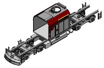
14 Clip Volume Section Clip Tools There are four methods for creating a clip volume by section plane. Place Fitted Section (three methods). A Fitted Section is a section cut throughout the XY, YZ or XZ plane relative to the Auxiliary Coordinate System. Apply Clip By Section Plane located in the Create Clip Volume tool settings. Here is the Top View and Isometric View of the train engine and tanker. User: Examples Project: Plant File:...\Designs\BSI700 R0100 RRTrack.dgn Top View 3D View Control 18 Sep-09


15 Clip Volume Isometric View in Illustration mode In this example, a Place Fitted Section is used and an XY plane is created in the Isometric view. The Clip Element is displayed in both views with editing handles active. Sep D View Control


16 Clip Volume Here are the results after moving the Clip Element Handles in the XY direction. The Top view shows the Clip Element but the Clip Volume is displayed in the view selected when creating the Clip Volume, which was the Isometric view. Here is the Clip Volume after Selecting the Show or Hide Clip Element tool. Clip Volumes and View Attributes The View Attributes dialog includes Clip Volume Settings. When a view contains a Clip Volume, the View Attributes dialog will display a Clip Volume collapsible section. The settings on this section provide various ways to display the Clip Volumes. In this view, the Clip Volume Settings of the View Attributes Settings are set to display the Forward volume of the Clip Element with the From View option enabled. The Back, Cut and Outside options are disabled. 3D View Control 20 Sep-09


17 Clip Volume Here is the same view with different options selected from the Clip Volume Settings. Clip Volume Settings and Display Style When a Display Style is created or an existing style is modified, enabling the Clip Volume box in the Display Style window will place the style as an additional Sep D View Control


")
18 Clip Volume option in the Clip Volume Settings. Clicking on the magnifying glass will open the Display Styles dialog. Applying a clip volume You can use a clip volume to isolate a part of the model so that you can work on it without the confusion from the display of other parts of the model. Exercise: Applying a clip volume by 2 points. 1 Set the following in the File Open dialog: Project: Plant 2 Open BSI700 A0101 PumpHouse.dgn. 3 From the View Control or the Clip Volume toolbox, select Clip Volume (4 + P) with the following tool settings: Apply Clip Volume By 2 Points Display Clip Element: Enabled 3D View Control 22 Sep-09
 as it knew which view to apply the command to.")

19 Clip Volume Create Dynamic View: Disabled 4 In the View Rotation toolbox, select Top View. Note: This View Rotation was transparent (you stay in the Clip Volume command) as it knew which view to apply the command to. 5 Enter data points to create a Clip Element. 6 Enter a data point in the View, to accept the clip volume. 7 From the View Control or the Clip Volume toolbox, select Clip Volume and Show or Hide Active Clip Element, then select view. The clip element will disappear. 8 Use Shift + middle mouse button (press in), or select Rotate View to rotate the View. Sep D View Control
20 Clip Volume Note that only the elements in the clip volume are visible during the rotation. 9 In the View Rotation toolbox, select Isometric View. 10 Fit View. No other elements appear in the view. 11 To remove the Clip Volume select the Clear Clip Volume tool and enter a data point in the view. Exercise: Applying a clip volume by Section Clip Tools. 1 Set the following in the File Open dialog: Project: Plant 2 Open BSI700 A0101 PumpHouse.dgn. 3 From the View Control or the Clip Volume toolbox, select Clip Volume (4 + P) with the following tool settings: Section Clip Tools Apply Fitted Section XY plane Display Clip Element: Enabled 3D View Control 24 Sep-09

21 Clip Volume Create Dynamic VIews: Disabled 4 In the View Rotation toolbox, select Top View. 5 Enter 2 data points from top to bottom, to create a section through the Pump House. 6 In the View Rotation toolbox, select Isometric View. Sep D View Control

22 Clip Volume 7 Open the View Attributes dialog using the View Control tool or by pressing Ctrl+B. Note: Since a clip volume exists in View 2, there is a Clip Volume Settings tab. The forward and back view style of the section plane are displayed on the Clip Volume Settings tab, and are set to From View. 8 Select the Outside option for the Back area of the section plane and the view displays dashed lines to indicate the Back of the section plane is now hidden. 9 Enable the display of the Cut area. The From View will display by default. 3D View Control 26 Sep-09
 and select the section clip element.")
23 Clip Volume 10 Change the display option of the Forward area of section plane to Outside. The new display of the clip volume section should look like the following view. 11 Use the Element Selection tool (1) and select the section clip element. 12 The boundaries of the interactive clip element display. Sep D View Control


24 Clip Volume 13 Move the green handle to re position the section plane and move the blue handle to modify the size of the Forward area of the section plane. Clear the clip element selection by a data point in the view. Note: You can right click on the green arrow and Flip Direction, Clip All Sides or Unclip All Sides or right click on a blue arrow and can Toggle Clipping, Clip All Sides or Unclip All Sides. Toggle Clipping will change the blue arrow to a blue bolt. 14 Modify the Clip Volume Settings: 3D View Control 28 Sep-09
25 Clip Volume 15 To remove the Clip Volume select the Clear Clip Volume tool and enter a data point in the view. Manipulating a clip volume from a second view With a clip volume active, you can restrict the display of elements to just those that you want to see. Once a clip element has been created, you can manipulate it to change the clip volume and the information being displayed. If you later move, or modify a clipping element, the clip volume is also moved or modified. If you delete a clipping element, the view clipping is removed. Clipping elements can be manipulated or modified with the standard MicroStation tools. Once a clip volume has been applied to a view, you can switch the clipping on and off in the View Attributes dialog using the Clip Volume check box. You can toggle display of the clip element using the Show or Hide Clip Volume Element icon in the tool settings. Exercise: Manipulating a clip volume 1 Continuing in BSI700 A0101 PumpHouse.dgn, select Clip Volume (4 + P). 2 Open and Tile Views 1 and 2, set View 1 to Front and set View 2 to Isometric then Fit View in each window. 3 From the Clip Volume tool settings, select: Section Clip Tools Apply Fitted Section XY Plane Sep D View Control


26 Clip Volume 4 Enter a data point in view 2. 5 Select Move Element (3 + 2). 6 In View 1, snap to the clip element and move it in the Z direction. View 2 displays the new Clip Volume. Experiment with the blue handles to make more changes to the Clip Volume. Here is an example: 7 To remove the Clip Volume select the Clear Clip Volume tool and enter a data point in the view. Saving clip volumes You can save clip volumes as named fences in the current file, for later use. You then can apply them to any view. You can also create a Dynamic View, more on that later. Exercise: Save the clip volume 3D View Control 30 Sep-09

 and click the Expand arrow at lower right of tool settings. 5 Click Create Named Fence From Clip Volume.")
27 Clip Volume 1 Continuing in BSI700 A0101 PumpHouse.dgn, make View 2 the active view. 2 Ensure that the View Attributes > Presentation > Clip Volume attribute is enabled in all views. 3 Create a 2 point Clip Element in View 1 and apply the Clip Volume in View 2. The image should be similar to the following. 4 Select Clip Volume (4 + P) and click the Expand arrow at lower right of tool settings. 5 Click Create Named Fence From Clip Volume. 6 In the Name field, type the name Front Wall and press Enter. Sep D View Control

 with the following tool settings: Apply Clip Volume By 2 Points Display Clip Element: Enabled Create Dynamic")
28 Clip Volume You now can apply this clip volume to any view. Working with multiple clip volumes Each view in a model can have a clip volume assigned to it. These can be identical, or they can be different clip volumes. Exercise: Create a second clip volume 1 Continuing in BSI700 A0101 PumpHouse.dgn, select Clip Volume (4 + P) with the following tool settings: Apply Clip Volume By 2 Points Display Clip Element: Enabled Create Dynamic Views: Disabled 2 In View 1, enter data points to isolate the back wall. 3 Enter a data point in View 3. 4 Fit View 3. 3D View Control 32 Sep-09
29 Clip Volume Views 2 and 3 now have different clip volumes applied to them. 5 Save the clip volume as a named fence named Back Wall. Exercise: Apply saved clip volume to a view 1 Continuing in BSI700 A0101 PumpHouse.dgn, make View 4 the active view. 2 Select Clip Volume (4 + P) and select the named fence Front Wall in the tool settings. 3 Click Apply Clip Volume By Named Fence. Sep D View Control


30 Clip Volume The view updates to display only the pump house front wall. 4 Select the named fence Back Wall in the tool settings. 5 Click Apply Clip Volume By Named Fence. The view updates to display only the back wall. 6 You can now rotate or control other aspects of the displayed clip volume. Saving clip volumes in this manner lets you quickly set up views to work on specific parts of a design. Once a clip volume is defined for a view, it remains with that view until you clear it. Tools such as the Fit View tool will not change the extents of a clip volume. Exercise: Clear a clip volume 1 Continuing in BSI700 A0101 PumpHouse.dgn, click Clear Clip Volume in the tool settings. 2 Enter a data point in View 2. 3 Fit View 2. 3D View Control 34 Sep-09


31 Clip Volume The entire model is displayed again. Using a clip mask A clip mask has the opposite effect to that of the clip volume. A clip volume defines what to display, but a clip mask defines what not to display. Procedures for creating and using clip masks are identical to those for clip volumes. You can apply clip masks to views that have had a clip volume applied. Similarly, you may want to work on part of a model, while hiding another part of it. If the elements all are on the same level, you can use the Clip Mask tool to mask the elements that are not required. Using 3D Clip Masks you can easily create cut away drawings. Sep D View Control


32 Clip Volume Exercise: Apply and clear a clip mask 1 Continuing in BSI700 A0101 PumpHouse.dgn, make View 2 the active view. 2 Select Clip Mask (4 + A) from the view control toolbox. The tool settings are similar to the Clip Volume tool. The named fences you created previously can be used with clip masks too. 3 Select the named fence Back Wall in the tool settings. 4 Click Apply Clip Mask By Named Fence. The view updates and the back of the pump house is masked from the view. Fitting and rotating the view will not cause it to reappear. Though you can Fit and Rotate the clip masked view. Clearing a clip mask is the same as a clip volume. 5 Click Clear Clip Mask in the tool settings. 6 Enter a data point in View 2. 7 Select File > Close. 3D View Control 36 Sep-09
33 Display Styles Dialog Display Styles Dialog The Display Styles Dialog is for modifying and creating custom display styles or render modes. DIsplay Styles can come from a DGNLI B or can be stored in the active DGN. Like similar Styles dialogs (Text, Dimensions, etc.) you can Update from Library to make sure you are using the latest styles. You can access the Display Styles Dialog from the following locations: Settings > Display Styles... or Tools > View > View Control Select from the View Toolbox the Open Display Style Dialog icon. Note: Standard display styles are provided with MicroStation V8i, and cannot be deleted. Sep D View Control

34 Display Styles Dialog Understanding Display Style dialog tools. 1 Wireframe Tool settings: No settings 2 Hidden Line Tool settings: Display: Hidden Line 3 Filled Hidden Line Tool settings: Display: Filled Hidden Line 4 Smooth Tool settings: Display: Shaded 3D View Control 38 Sep-09
35 Display Styles Dialog 5 Illustration Tool settings: Display: Shaded Display Visible Edges: Enabled (Black) Background Color: Enabled (White) Note: The Display Styles Dialog setting Usages when enabled, determines if the display mode is created in view window or Clip Volume or both. Exercise: Create a custom display style 1 Open BSI700 S0501 UnloadingPlatform.dgn, make View 2 the active view. 2 Select Settings > Display Styles... 3 Select New and type over Untitled with the name Custom Display. 4 Set the Display Styles settings as follows: Display: Shaded Display Shadows: Enabled Enable No Material: Select the Material option Select magnifying glass: Select Platform Frame material Enable Background color: Select Gray #48 option Enable Usages: View Sep D View Control
. You can turn perspective on specifically using the View Perspective tool.")
36 Perspective 5 In View 2, select the View Display Mode tool drop down arrow and select Custom Display. Perspective Every time you turn on perspective in a view, you turn on the Camera (View Attributes > Camera). You can turn perspective on specifically using the View Perspective tool. A single data point in the view center starts the 3 point perspective, and movement away from the center changes the amount of perspective. Selecting the View Perspective tool and double clicking in the center of the view sets the view to parallel projection, or turn off the Camera in View Attributes. Additional options are available if you click and hold the View Perspective tool or open it as a toolbox. Right click on any tool to Show All tools. View Perspective interactively set perspective in a view Wide Angle sets perspective in a view to match an extra wide angle camera lens Normal sets perspective in a view to match a normal camera lens Telephoto sets perspective in a view to match a telephoto camera lens Two Point Projection sets perspective in a view to 2 point projection. Hidden by default 3D View Control 40 Sep-09


37 Saved Views dialog Camera Off turns off a view camera and return to parallel projection Saved Views dialog Used to name, save, delete, import, apply and recall saved views. Saving a 3D view allows you to quickly recall a view with specific attributes. It is important to create and use Saved Views in 3D, since you will want to return to a known position many times. They are helpful for design, navigation, rendering and animation. Camera and Clip Volume settings are available for saving or recall. Open the dialog by selecting Utilities > Saved Views, selecting View Save/Recall from a view window control menu, or pressing F6. Understanding the Saved Views dialog The Saved Views dialog contains controls that are used to apply a saved view to a view in the design file. The list box shows the name, description and model of each view saved. To apply a saved view, use the following options: Apply to Selected Views. Select this tool and click in a selected view window. Sep D View Control


38 Saved Views dialog Apply to open views. All opened views will display the Saved View. Double click the entry in the Saved View dialog list will display the Saved View in the Active View. Active File This icon displays optional settings by clicking on the drop down list box. Note: A link is a pointer to project data and a link set is created when you use Project Explorer (File > Project Explorer). Create Saved View Opens the Create Saved View dialog where you name and describe the view you are saving. The view can be a saved, section, elevation, detail or plan view. A Clip Volume can also be added to a Saved View Option or a Dynamic View can be created. Exercise: Create a Saved View 1 Open BSI700 S0501 UnloadingPlatform.dgn, open Views 1 through 4, select to Window > Tile, and then Fit View (4 + 5) for each view. 2 Set Display Mode to Wireframe for each view. 3D View Control 42 Sep-09
.")


39 Saved Views dialog 3 Window in on the top of the Unloading Platform in View 4 (Right View). 4 Set Display Mode to Smooth with Shadows and apply the View Perspective Extra Wide Angle. Pan and Rotate to adjust if needed. 5 Press F6 to open the Saved View dialog, click Create Saved View, and save the new view in View 4: Name: Top Platform Description: Top platform with wide angle view 6 Click in View 4 to select the source view. Sep D View Control

40 Saved Views dialog 7 In the Saved Views dialog, set the View number to View 3 and double click the Top Platform saved view in the saved view list box. 8 In the Saved View dialog list box, click on the area below the header Clip Volume to select an existing clip volume. 3D View Control 44 Sep-09
41 AccuDraw in 3D Module Overview AccuDraw is an intelligent drawing aid that interprets the position of the pointer relative to previous data points, view orientation, and coordinate system. Using AccuDraw, you can quickly enter additional data points that build on those entered previously. Module Prerequisites Knowledge of AccuDraw in 2D Knowledge of basic 3D view controls and 3D planes Module Objectives After completing this module, you will be able to: Design with AccuDraw in a 3D environment Use Auxiliary Coordinate Systems to control drafting planes Use AccuDraw 3D shortcuts Sep AccuDraw in 3D
42 Introductory Knowledge Introductory Knowledge Before you begin this module, let's define what you already know. Questions 1 Name the two basic AccuDraw interface components. 2 What must have the focus for AccuDraw shortcuts to work? 3 What are the operational steps when using AccuDraw? 4 How do you place the AccuDraw compass at a snap point? Answers 1 AccuDraw compass and AccuDraw window. 2 The AccuDraw window Enter a data point using either precision input, or a data point, to fix the location of the compass. 2. Move the pointer in the direction in which you wish to draw. 3. Without using the pointer to put focus into the AccuDraw window s keyin fields, enter the desired distance value. 4 Use AccuSnap, or issue a manual tentative snap, and use the AccuDraw shortcut <O>. AccuDraw in 3D 48 Sep-09
43 The AccuDraw Drawing Plane The AccuDraw Drawing Plane AccuDraw was designed to work with the 3D drawing environment. You can work in a view other than one of the orthogonal views (Top, Front, and Right), but still draw in the orthogonal planes. Rotated views such as Isometric or Right Isometric display a design more clearly. When working in these views, if you want to draw an object on the Top or Front plane, you can simply rotate the AccuDraw compass to that plane using an AccuDraw shortcut. You do this by rotating AccuDraw s compass to an orthogonal plane with one of the shortcuts V (view), T (top), F (front), or S (side). Working in the Isometric view, you can use AccuDraw shortcuts to rotate its compass to the Top (T), Front (F), Side (S) or View (V) orientation Note: Remember that the focus must be in the AccuDraw window for its shortcuts to work. Press F11, or press Esc and then the space bar to move focus to it. It is recommended that you work in the Isometric view with the Top, Front and Right views open, placed behind the Isometric view. 3D Element Placement Placing elements in a 2D file is like drawing on a sheet of paper. All elements are on 1 plane, the x,y plane. When you place the same elements in a 3D file, by Sep AccuDraw in 3D

44 3D Element Placement default they are placed in the AccuDraw drawing plane. The AccuDraw drawing plane can be rotated to match the view being used, or defined to be a particular rotation. In the following exercises, you will draw an open rectangular box using 2D blocks. Exercise: Open the model and draw the base surface 1 Set the following in the File Open dialog: User: untitled Project: Everything3D 2 Open AccuDraw_3D.dgn from the class data set. This model displays the ACS triad, which indicates the directions of the 3 axes, in each view. You can toggle the display of the ACS triad in the View Attributes dialog. 3 Select Workspace > Preferences, and then the Task Navigation category and set Presentation to Dialog. 4 In the Task dialog, click on the Solids Modeling task. First, using the Top view, you will draw the base of the box. You will use AccuDraw to input precise dimensions. Effectively, this part of the exercise will be no different from working in 2D. 5 Select Place Block (W + 1). AccuDraw in 3D 50 Sep-09
45 3D Element Placement 6 Enter a data point in the lower left corner of the Top view. 7 Move the pointer to the right and, with it indexed to AccuDraw s x axis, type 1.5. Do NOT enter a data point. 8 Move the pointer upward and type Enter a data point to complete the block. 10 Fit each view. The block appears as a line in both the Front and Right views, where it is edge on to the views, like looking at a sheet of paper edge on. Next, you will use the Isometric view to draw the corresponding front and right faces of the box. You may remember that each view has an active depth, where data points fall by default if you do not snap to an element. Here, you will snap to the existing block that you just drew and use AccuDraw to keep the pointer at that depth in the view. Exercise: Use Isometric views to draw corresponding faces for the box 1 Continuing in AccuDraw_3D.dgn, select Place Block (W + 1). 2 In the Isometric view, snap to the left end of the existing block and accept with a data point. 3 With focus on AccuDraw, press <F> for the Front rotation. Sep AccuDraw in 3D
46 3D Element Placement 4 Move the pointer to the right, snap to the endpoint and, with it indexed to AccuDraw s x axis, then press <X>, to lock to the x. 5 Move the pointer upward, type 0.5, and enter a data point to complete the block. 6 Fit each view. For the right face, you can snap to existing elements to place the points. 7 Select Place Block (W + 1). 8 Press <S> for Side rotation. Note: Press F11 to put focus in the AccuDraw window. 9 In the Isometric view, snap to the bottom left end of the base and accept with a data point. AccuDraw in 3D 52 Sep-09
47 3D Element Placement 10 Continuing in the Isometric view, snap to the top of the front surface and accept with a data point. As you do this, check in the Front and Right views to ensure that you are snapping to the correct points and that the block is being placed correctly. 11 Fit each view. To complete the box, you can use the Copy tool to copy the existing faces creating the opposite sides. When you copy an element in 3D, it retains its current orientation. That means that a vertical face remains vertical, a horizontal face remains horizontal, and so on. Exercise: Copy the existing faces to complete the box 1 Continuing in AccuDraw_3D.dgn, select Copy Element (3 + 1), with the following tool setting: Copies: 1 Sep AccuDraw in 3D
48 3D Element Placement 2 In the Isometric view, identify the block representing the back face at its lower right vertex. The face is attached to the pointer. As you move the pointer in the other views, the front face element retains its current orientation. 3 Snap to the front right vertex of the base block. 4 Enter a data point to complete the copy and reset. AccuDraw in 3D 54 Sep-09
49 3D Element Placement 5 In the Isometric view, identify the block representing the right face at its lower right vertex. 6 In the Isometric view, snap to the back right vertex of the base block and accept to complete the copy. 7 Reset. 8 Click the View Display Mode view control and change the Isometric view s display to Hidden Line. 9 Use the Rotate View tool to rotate the Isometric view and verify that you have correctly drawn all the surfaces for the open top box. Sep AccuDraw in 3D
50 3D Element Placement As you can see, placing elements in 3D is no more difficult than in 2D. In the exercise, you used MicroStation s views to correctly orient the elements. Of the 4 views, the Isometric view best displays the model. You can see the 3 faces quite clearly. Using AccuDraw s rotated drawing plane You can place elements in the Top, Front and Side alignments using AccuDraw s <T>, <F> and <S> shortcuts. AccuDraw s drawing plane lets you work in any view, while still maintaining the correct plane for the elements being drawn. You can still snap to elements that are not on the current drawing plane and AccuDraw responds accordingly. As you draw in 3D, you may observe the drawing plane axes change as you enter data points. The alignment of the drawing plane depends on the tool being used and the location of the previous data points. For 3D models, the 3 previous data points are considered, as this is the minimum requirement to describe a planar surface. Where less than 3 data points have been entered, the view orientation is also considered. Additional shortcuts <B> Base Rotation: Rotates the drawing plane to align with the active ACS or the rotation of the view. <E> Cycle Rotation: Rotates between 3 main planes; top, front, and side. Pressing E rotates the drawing plane first 90 about its x axis, then 90 about its y axis, and then back to its original rotation. In the following exercises, you will work in the Isometric view and let AccuDraw correctly align the elements. As you work through the exercise, use the other open views to check the orientation of the element being drawn, by maximizing and shrinking the Isometric view. Exercise: Automatic drawing plane rotation in AccuDraw 1 Continuing in AccuDraw_3D.dgn, Pan to an open area of the model. 2 Select Place Block (W + 1). AccuDraw in 3D 56 Sep-09
51 3D Element Placement 3 In the Isometric view, place 2 orthogonal blocks as shown. 4 Continuing with Place Block, snap to the vertical face upper right corner. 5 Press <T> to rotate AccuDraw s drawing plane to Top. Sep AccuDraw in 3D
52 3D Element Placement 6 Snap to the lower right vertex of the base. AccuDraw uses the 2 data points plus the view to set the drawing plane orientation. This results in a drawing plane that is not always in alignment with any of the standard Top, Front or Side drawing planes. 7 Snap to the lower left edge of the base and accept with a data point. AccuDraw s drawing plane now aligns itself with the plane of the 2 nonplanar data points. 8 Reset to complete. Non orthogonal rotation Quite often, you will need to rotate the AccuDraw compass to a non orthogonal plane; one that is not the Top, Front or Side. Besides the standard non planar data AccuDraw in 3D 58 Sep-09
53 3D Element Placement points and view rotation, or non planar snapping, several other methods are available. The most common is to use an AccuDraw shortcut. RQ Rotate Quick provides quick, non persistent rotation RA Rotate ACS allows you to persistently rotate x and y plane about an origin point. You can clear it by using a standard rotation like T,F, S, V WA Save an ACS rotation GA Recall an ACS rotation E Cycle Rotation Important when using another ACS since T, F or S will break you out of existing ACS RX Rotate about x axis RY Rotate about y axis RZ Rotate about z axis RE Rotate AccuDraw compass to match orientation of an element RV Rotate Active View to orientation of AccuDraw compass Exercise: AccuDraw and Quick Rotation 1 Continuing in AccuDraw_3D.dgn, select Edit > Undo to undo the placement of the last inclined plane. 2 Select Place Block (W + 1). 3 Press F11 and then press <T> for top rotation. 4 Following the status bar prompt, snap to the upper left vertex of the vertical face and accept with a data point. Sep AccuDraw in 3D
54 3D Element Placement 5 Press <RQ> and, following the status bar prompt, snap to the lower left vertex of the base, then accept the new rotation with a data point. 6 Snap to the right lower vertex of the base and accept the new block with a data point. Note: An alternate method is to use Place Block with the Method set to Rotated. To keep a persistent rotation, you can use the AccuDraw shortcut <RA>. Exercise: Using RA to keep a rotation AccuDraw in 3D 60 Sep-09
55 3D Element Placement 1 Continuing in AccuDraw_3D.dgn, select Place Circle (W + 5) with the following tool setting: Method: Center 2 Snap to the upper left vertex of the vertical face, press F11, and then press <O> to set the AccuDraw origin, but do not enter a data point. 3 Press <RA>, keeping the snap point the same, and enter a data point to accept the origin. 4 Snap to, and accept, the upper right vertex of the vertical face to show the x axis direction. Sep AccuDraw in 3D
56 3D Element Placement 5 Snap to, and accept, the lower left of the base to set the y axis direction. 6 Press the space bar to change to the rectangular coordinate system. AccuDraw in 3D 62 Sep-09
57 3D Element Placement 7 Snap to, but do not accept, the left midpoint of the inclined plane and lock the y axis by pressing <Y>. 8 Press <K> to open Keypoint Divisor dialog and set the divisor to 3. 9 Snap to left third of the long edge of the base to set the x axis distance, and enter a data point to accept the center point of the circle. Sep AccuDraw in 3D
58 3D Element Placement 10 Type a distance of 0.2 for the radius and accept with a data point. Save the rotated ACS with AccuDraw shortcut <WA> and recall it with <GA>. A quick rotation method is to rotate to an elements plane. Exercise: Quick Rotation to an element 1 Continuing in AccuDraw_3D.dgn, with focus on AccuDraw, press <T> to set Top rotation. 2 Select Place Circle (W + 5), with the following tool settings: Method: Center 3 Press F11 to put focus in the AccuDraw window. 4 Snap to, but do not accept, the midpoint of right edge of the inclined plane and press <O> to set the AccuDraw origin at the midpoint. 5 Press <RE> to Rotate to Element. AccuDraw in 3D 64 Sep-09
59 3D Element Placement 6 Align the compass to the right inclined edge. 7 Enter a data point to accept the rotation. 8 Index to the left and press Enter. 9 Snap to a point one third of the way along the bottom edge and enter a data point to place the center of circle. Sep AccuDraw in 3D
60 3D Element Placement 10 Index to any axis and type a radius of 0.2. Other tools that rely on the plane orientation also can be used with AccuDraw. For example, the Mirror, Rotate Element, and Array tools all use the plane orientation to define the direction of the mirror, or the axis of rotation. Locating elements relative to others There will be occasions when you will locate elements relative to others already present in the model. In the following exercise, you will place a SmartLine to represent a center line for a pipe. Exercise: Draw the center line 1 Continue in AccuDraw_3D.dgn. 2 Open the 01_AccuDraw Exercise model. 3 Set the View Display Mode to Smooth with the following tool settings: Display Edges: Enabled Display Hidden Edges: Enabled 4 Make the Drawing tasks the active tasks in the Task Navigation dialog. 5 Select Place SmartLine (Q + 1) with following settings: Segment Type: Lines Vertex Type: Rounded AccuDraw in 3D 66 Sep-09

61 3D Element Placement Rounding Radius: 1.5 Join Elements: Enabled 6 In the rotated view, snap to the vertex at the point labeled Start here and accept with a data point. 7 Press <T> to switch to the Top plane. 8 Move the pointer down to the left and, with it indexed to the y axis, press <Enter> to constrain the point to this axis. (Do not enter a data point.) Sep AccuDraw in 3D
62 3D Element Placement 9 Type a distance of 35 for Y, and accept with a data point. 10 Staying in the Top plane, index to negative Y and press Enter. 11 Snap to the center of lower, open cylinder face and accept with a data point. AccuDraw in 3D 68 Sep-09
63 3D Element Placement As you snap to the vertex, AccuDraw displays a dashed line, which is perpendicular to the x axis, back to the point being placed. This lets you locate the y distance using a 3D snap. 12 Press <F> for Front rotation. 13 Index to the negative y axis and press <Enter> to constrain the next point to the y axis. 14 With the pointer still snapped to the lower center open cylinder face, accept with a data point. 15 Press <T> for Top rotation. 16 Index to the negative y axis and lock by pressing <Y>. Sep AccuDraw in 3D
64 3D Element Placement 17 Type 30 and accept with a data point. 18 Reset to complete. 19 Rotate to see the other side. 20 Repeat for the other 2 directions. 21 Select File > Close. AccuDraw in 3D 70 Sep-09

65 Using Auxiliary Coordinate Tools Using Auxiliary Coordinate Tools You can define new x and y axes in your design plane and save them as an auxiliary coordinate system (ACS). You can define several auxiliary coordinate systems and quickly choose any of them to use. At any time, you can make one ACS active per view. Auxiliary coordinate systems can be particularly helpful in 3D design, where they facilitate placing elements on planes at different depths and orientations. By using an ACS that corresponds to the location and orientation of a particular element, you can enter data points relative to that element rather than the global origin. Once an ACS is active you can use it with AccuDraw and with precision input keyins (such as AX= and AD=) to perform precision input with respect to the auxiliary coordinate systems. You can also use AccuDraw shortcut key ins to define and activate auxiliary coordinate systems. MicroStation provides specific tools for creating, modifying, importing and selecting Auxiliary Coordinate Systems. You can find the tools by selecting Utilities > Auxiliary Coordinates or right click and turn on the tool in the Primary Tools toolbox. An auxiliary coordinate system (ACS) is a coordinate system with an orientation, and/or an new origin, different from those of the DGN file coordinates (the Global Origin). Although not exclusively a 3D concept, an ACS is most useful in 3D modeling as a drawing aid. Tools from left to right are: Create a new ACS Sep AccuDraw in 3D
66 Using Auxiliary Coordinate Tools Copy ACS Delete ACS Import ACS Define ACS (Aligned with Element) Define ACS (By Points) Define ACS (Aligned with View) Define ACS (Aligned with Reference) Rotate ACS Move ACS Apply ACS to Selected View Select ACS Active Depth is no longer used, because the location of unsnapped points is controlled by the ACS for a view. Instead of Depth Lock, you now can enable ACS Plane Snap to force unsnapped points to fall on the plane of the ACS. Auxiliary Coordinates dialog tool features A new ACS can be created using the Create a new ACS tool in the dialog. You do NOT need to create an ACS before you define it. Using a Define ACS tool will create an ACS for you. A list box now displays the active ACS on the top line and all ACS s in the active model. All ACS tools are available within the dialog. Ability to create, copy, delete or import an ACS. Make an ACS active by double clicking on ACS name in list or right click on ACS name and select Set Active from options list. Other options include ability to match the coordinate system of selected ACS to the active ACS or global coordinates for the model, and deleting or renaming an ACS. Left click on the Type and change it to None, Rectangular, Spherical, or Cylindrical. AccuDraw in 3D 72 Sep-09
67 Using Auxiliary Coordinate Tools Important Notes on the ACS System The active ACS for a view is NEVER a named ACS, it is a copy. You can set it from a named ACS and as long it still matches the named ACS it will display the name to show where it originated from. For example, set a named ACS for a view, then change it, by using the AccuDraw shortcuts RA, E, Define ACS by Points tool, etc. Only the active ACS for the view is changed and the connection with the named ACS is broken (the view becomes unnamed). Otherwise, you would have to be very careful not to inadvertently redefine your carefully setup named ACS. The reverse is also true. Set a named ACS on the view, then modify the named ACS directly (for example, enter new origin values for a named ACS using the ACS dialog). The active ACS values are un affected and just the connection with the named ACS is broken. In both cases you will see that the active ACS loses its name immediately in the ACS dialog. The View Independent toggle (right click on a named ACS in the ACS dialog to select command) is a little different. It is currently only a property of the active ACS, not a named ACS. As long as the other settings are the same you can toggle it on/off without breaking the connection to the named ACS, but if it is left view independent MicroStation will stop showing the name when you re open the file because the active ACS would have been saved without a fixed rotation. With a view independent ACS the xy plane is always aligned parallel to the view at the defined depth or the equivalent to active depth in V8i. So the main thing to understand is that a view's ACS is completely independent of any named ACS, the name is just a helpful hint as to how it was setup that is only valid as long as nothing is changed. ACS and Depth Lock MicroStation V8i no longer has a Depth Lock. It is replaced by the ACS Plane Lock. The ACS always defines your working plane now, it is not going to be some static thing that you just leave at 0,0,0 with an identity rotation and never use. To mimic depth lock you can setup a view independent ACS, which is the default for files that did not have ACS Plane Lock enabled and what the set active depth tool now does. Then turn on ACS Plane Snap from Settings > Locks > ACS Plane and ACS Plane Snap or use AccuDraw shortcuts LP, LA and/or LS (see below). Sep AccuDraw in 3D
68 Using Auxiliary Coordinate Tools ACS and Depth Lock Questions and Answers 1 Do I need to set up view oriented ACS for each rotated view? You certainly can, you could have an ACS for your elevation view that is always front and your plan view that is always top, etc. However, if you typically work with a single view and frequently switch between standard rotations to draw on different planes aligned to the view, changing the ACS would get tedious. A view's ACS can now specify that it is view independent, in other words, defines a point that a plane aligned with the view passes through, effectively the active depth concept but without having to worry about viewing operations inadvertently changing it out from under you. If you have display of the ACS enabled for a view, a view independent ACS displays the triad arrows with a dotted style instead of solid. 2 How does this affect the coordinate readout in the Status Bar. First, use Running Coordinates (right click on the Status Bar and select). Then by left clicking on the Running Coordinates box in the Status Bar you can choose to display: Position, Delta, View Delta, Distance, ACS Position, or ACS Delta. 3 I do heavily rely on view active depth, for rotating views. I would have thought that when no ACS is enabled then the active depth and depth lock should work as before. The ACS is effectively always enabled. ACS Plane Lock now just controls whether viewing operations and AccuDraw shortcuts for T, F, S are relative to the design coordinates or the ACS. It also controls whether the ACS scale will be used (in the case where you have explicitly set a scale other than 1.0 for your ACS). 4 We use SET TPMODE LOCATE how does this affect us? It should not affect you. To always report coordinates relative to the global origin, use tpmode locate. If you do not want the snap point projected to the active ACS Plane (i.e. active depth) turn off ACS Plane Snap just as you would have had to turn off Depth Lock in previous versions. Use TPMODE ACSLOCATE only if you set a specific ACS for you view, and the expectation here is that these users will use the ACS tools and ACS dialog and not use the old active depth tools. You can also change your mode with Running Coordinates. 5 Do I need to use ACS Plane Lock and ACS Plane Snap Lock always in my workflow now? AccuDraw in 3D 74 Sep-09
69 Using Auxiliary Coordinate Tools The ACS locks is for someone who has setup an explicit ACS to a meaningful location/orientation. ACS Plane Lock is not needed to control whether un snapped points are projected to the ACS Plane, that always happens now. 6 How do I save my ACS s? ACS s are saved with Save Settings. Set Active Depth Tool The Set Active Depth tool was left in the interface because it is a familiar and easy to use tool for people that were not accustomed to using an ACS. The implementation of the tool has changed to define a view independent ACS at the point you select. Turn the View Attribute for ACS on so you can see what it is doing. AccuDraw Shortcuts for ACS Although using ACS s may seem complicated, AccuDraw uses them as a basic part of its 3D functionality, permanently storing arbitrary rotations. It is not necessary to learn much about ACS s to use them effectively with AccuDraw. AccuDraw drawing plane shortcuts for Top, Front and Side are relative to the active ACS rather than the Default coordinate system. LP Lock ACS Grid Plane Toggles ACS Grid Plane lock, which toggles the ACS Plane and ACS Plane Snap locks, and the Grid view attribute for all views. Very helpful shortcut. The F8 key is mapped to the same command. LA Toggles ACS Plane lock. LS Toggles ACS Plane Snap lock. LZ Toggles Sticky Z Lock, which can be used in conjunction with ACS Plane Snap Lock to force a series of snap points to lie on the active ACS' XY plane (Z=0). One possible AccuDraw and ACS Workflow 1 Draw/Reference an element for the rotation you need. 2 Use AccuDraw shortcut <RE> for Rotate [compass to] Element, and AccuDraw will rotate to the orientation of this element. 3 Use AccuDraw shortcut <WA> for Write ACS, and a new ACS will be created with the name you choose. Sep AccuDraw in 3D

70 Using Auxiliary Coordinate Tools 4 Use AccuDraw shortcut <GA> for Get ACS, this gives you a menu to select your ACS s. When opening the ACS dialog you will see your ACS Systems, right click on the title list of this menu, and you can turn on and view the rotation of your ACS. Exercise: Creating and drawing on a new ACS. 1 Continuing in AccuDraw_3D.dgn, open the model 02_ACS_by_points. 2 Select the ACS By Points tool from the Auxiliary Coordinates dialog with the following tool settings: Type: Rectangular 3 Enter the new ACS origin at point 1 4 Define the x axis by placing a data point on point 2 5 Enter a data point on point 3 to identify the y axis direction, and the new ACS will display. 6 To create a new ACS, click the Create a new ACS tool in the dialog and type a name for the new ACS. 7 Double click the new named ACS. AccuDraw in 3D 76 Sep-09
71 Using Auxiliary Coordinate Tools It will become the Active ACS and will display on the first line or Active ACS line of the dialog. 8 Select Place Block with the following settings: Method: Rotated Area: Solid Fill Type: None Note: When drawing on a rotated ACS use the AccuDraw shortcut <LA> to lock the ACS Plane. 9 Enter the base point of the block at the midpoint of the edge between points 1 and Enter the second base point of the block at the midpoint of the edge between points 1 and 2. AccuDraw will automatically rotate orthogonal to ACS2. 11 Move the pointer along the green y axis for a distance of Render using the Smooth or Hidden Line View Display Mode. Sep AccuDraw in 3D
72 Define an ACS aligned with a reference file The following image shows a simple reference attached to the model. To set the ACS so that it is aligned with the ACS of the Reference, use the Define ACS (Aligned with Reference) tool. Select the Reference and the Reference ACS becomes the active ACS. ACS interaction with AccuDraw Use the AccuDraw shortcut <LA> to lock the active ACS plane. This will let you use the <T>, <F> and <S> shortcuts relative to the active ACS. Sep AccuDraw in 3D
73 Using Auxiliary Coordinate Tools Use the AccuDraw shortcut <LP> or default function key <F8> to turn on the ACS Plane, ACS Plane Snap and grid for all views. The following image shows the results of using the <LP> or <F8> shortcut. Separate ACS per View A new tool in the ACS toolbox lets you assign Auxiliary Coordinate Systems to each view. You can create an ACS for a view with the Define ACS by View tool. You can make the ACS view independent by turning on a check box. When a viewindependent ACS is active, and the ACS triad setting is enabled for the view, the X, Y arrows are displayed as dashed in the view. To retain the per view ACS setting for the next session, you must select File > Save Settings. When a model created in an earlier version is opened and the ACS Plane lock is not enabled, a view independent ACS with an origin of the view center at active depth is created. This lets you start working with the geometry created in the same place as it would have been in the earlier version (at the Active Depth). You may also right click on an ACS in the ACS dialog and select Set Active View. Projecting Points from and ACS to a Plane You can use a combination of an ACS and AccuDraw to project points, in the ACS z direction, from the ACS plane to the AccuDraw drawing plane. This technique lets you, for example, trace the boundary of a house on to a sloping roof line, as explained in the following workflow. Sep AccuDraw in 3D
74 Module Review How to Project Points onto a Rotated Plane: 1. Set up an ACS such that the Z direction is the desired projection. 2. Press F8 or <LP> to lock AccuDraw to the ACS Plane, Plane Snap and Grid Plane or use <LA> and <LS> if you do not want to see the grid. 3. Select the element placement tool, such as Place SmartLine. 4. Press F11, to set focus to AccuDraw. 5. Key in the AccuDraw shortcut RE. 6. In the tool settings, set: Update Current ACS: Off Move Origin: On 7. Select the element to which you want AccuDraw aligned and accept with a data point. 8. To commence drawing the element, snap to an element in the ACS plane and accept with a data point. The point is projected onto the AccuDraw drawing plane. 9. Add more points by snapping to elements in the ACS plane to project the points to the AccuDraw drawing plane. Module Review Now that you have completed this module, let s measure what you have learned. Questions 1 When you place elements in a 3D file, on what plane are they placed by default? 2 How can you move focus to the AccuDraw window? 3 Which view rotation best displays a model? 4 True or False: When you copy an element in 3D, it retains its current orientation. 5 What is the minimum requirement to describe a planar surface? 6 What does the AccuDraw shortcut <RA> do? AccuDraw in 3D 80 Sep-09
75 Basic 3D Solids Module Overview This module presents tools for Curves, Solids and Surfaces. When working with Solids it helps to think like a sculptor who starts out with a mass and cuts away what is not needed. Of course, in digital 3D you can add just as easily. Module Prerequisites Knowledge of 3D tools in MicroStation Knowledge of 2D Drawing tools in MicroStation Knowledge of AccuDraw in 3D Module Objectives After completing this module, you will be able to: Use new 3D modification and creation workflows Use existing and new 3D Primitives Apply new features of existing tools Sep Basic 3D Solids
76 Introductory Knowledge Introductory Knowledge Before you begin this module, let's define what you already know. Questions 1 Name the AccuDraw shortcut used to cycle through rotations. 2 What 3D primitive lets you create a box shaped object? 3 What is Feature Modeling? Answers 1 E. This shortcut will cycle through all orthogonal rotations. 2 Place Slab. 3 Feature Modeling tools let you create parametric feature based solids. That is, a parametric solid that is created from one or more features. Each part of a solids model created with these tools is a feature. Parameters used to create the features are stored in the design and may be edited. 3D Workflows All 3D modeling tools now have a unified workflow that covers that way that you select items for creation and modification, and how you can modify them interactively. For example, you can now select edges and faces of solids and surfaces for modification with Element Selection. Typically, selecting edges, faces, or vertices, for solids and surfaces is as follows: Generally select single items with a data point, and use Ctrl + data button for additional items. Faces select the solid/surface first, and then dynamics let you select face(s). Back Faces snap to an edge or vertex of a back face. Edges/Vertices direct selection, or through dynamic selection. Basic 3D Solids 122 Sep-09
77 3D Workflows Interactive handles to control 3D objects during creation Interactive handles let you control aspects of 3D objects during creation. For example, you can reverse the direction of surface normals interactively, during construction of fillets, by clicking the direction handles. Solids Modeling Task Contains basic Drawing tools plus 3D specific tools for creating primitive solids, extrusions, revolutions, converting solids to surfaces and vice versa, and the Draw on Solid and Modify Solid Entity tools. The first tool in the Solids Modeling task, Place SmartLine initially, is also a member of the Drawing task. When you press the left mouse button over the tool, you see a drop down menu from which a tool in the Drawing task can be selected. The Drawing task can be opened as a floating toolbox by selecting Open As ToolBox from the drop down menu. When a tool is selected in the Drawing task, the tool automatically becomes the top icon of the child task in the Solids Modeling task. Hint: Press F4 to see the current tasks at the pointer. Sep Basic 3D Solids

78 3D Workflows Surface Modeling tasks These tasks contain the Drawing toolbox, plus tasks for construction, and modification of surfaces and mesh elements. Basic 3D Solids 124 Sep-09

79 3D Workflows Feature Based Solids Modeling tasks MicroStation has advanced solids modeling construction and modification tools for parametric modeling using Feature trees. These are contained in the Feature Based Solids Modeling task. Sep Basic 3D Solids


80 3D Primitive Solids Alternate Display options exist for the Task Navigation dialog. Right click on the name of a task in the dialog itself or select an icon from the icons displayed aside of the Task name. List option is useful when learning a new task and Panel option exposes all tools. 3D Primitive Solids Many 3D solids can be created from 1 or more of the Primitive Solids models located in the Solids Modeling Task. The primitive models available include the Slab, Pyramid, Sphere, Cylinder, Cone, Elliptical Cone, Ellipsoid, Torus, Wedge, and Polyhedron. 3D Surface Primitives have been moved to the Surface Task. Each tool setting has the Method, Axis and required parameters to create the specific Primitive Solids: Method: Creation by Vertex, Edge, Face, Inscribe, Circumscribed, Center, Edge, or Diameter. Axis: Lets you choose how the axis for the element is defined. You can select from Points (AccuDraw), Screen X, Y, or Z, or Drawing X, Y, or Z. Screen is direction of the height is set to the screen's X, Y, or Z axis. Drawing is direction of the height is set to the drawing's, or model's, X, Y, or Z axis Basic 3D Solids 126 Sep-09

81 3D Primitive Solids Other settings are specific for each tool. Hint: Although the primitives dimensions can be specified in the tool settings, for placing a single primitive it is generally quicker to type these distances into the AccuDraw window. Slab Solid Probably the most useful of all primitives, the Place Slab tool can be used to draw any cubic object. Using this tool, you can construct a box shaped solid or surface. Element specific tool settings are as follows. Axis: Points (AccuDraw), Screen X, Y, Z, Drawing X, Y, Z Orthogonal: When enabled, the sides are perpendicular to the base. Length: If on, specifies the length. Width: If on, specifies the width. Height: If on, specifies the height. Slabs placed as Solid Place Sphere With this tool, you can construct a sphere with 2 data points. Element specific tool settings are as follows. Method: Center, Edge, Diameter Axis: Points (AccuDraw), Screen X, Y, Z, Drawing X, Y, Z Sep Basic 3D Solids
, Screen X, Y, Z, Drawing X, Y, Z Orthogonal: If on, the centerline of the cylinder is perpendicular to the base.")
82 3D Primitive Solids Radius: When on, specifies the Radius. Place Cylinder A cylinder is defined by 3 data points, the center of its radius, then the radius, and finally the height. Element specific tool settings are as follows. Axis: Points (AccuDraw), Screen X, Y, Z, Drawing X, Y, Z Orthogonal: If on, the centerline of the cylinder is perpendicular to the base. Radius: If on, specifies the radius. Height: If on, specifies the height. Hint: You can use the Modify Element tool to reposition the base or top of cylinders. Place Cone Similar to the Place Cylinder tool, the Place Cone tool requires a fourth data point to define the Top radius of the cone. A cone with its apex cut off by a plane parallel to its base is called a truncated cone or frustum. Element specific tool settings are as follows. Axis: Points (AccuDraw), Screen X, Y, Z, Drawing X, Y, Z Orthogonal: If on, the centerline of the cone is perpendicular to the base. Top Radius: If on, specifies the top radius. Base Radius: If on, specifies the base radius. Height: If on, specifies the height. Basic 3D Solids 128 Sep-09

, Screen X, Y, Z, Drawing X, Y, Z Primary Radius: If on, specifies the primary radius. Secondary Radius: If on, specifies the secondary radius.")
83 3D Primitive Solids Place Torus A torus is a round doughnut shaped object that is defined by 4 data points; the start point, the center point, the sweep angle, and the secondary radius. The primary radius is the one the torus is swept around and is the distance between the start point and the center point. The secondary radius defines the inner radius, or the radius of the torus circular section. Element specific tool settings are as follows. Axis: Points (AccuDraw), Screen X, Y, Z, Drawing X, Y, Z Primary Radius: If on, specifies the primary radius. Secondary Radius: If on, specifies the secondary radius. Angle: If on, specifies the sweep angle. Place Wedge A wedge is constructed by revolving a rectangular section about an axis. It is defined by 4 data points. The first data point defines a corner of the wedge, the second data point defines the center point of the wedge and the point to rotate about, the third data point defines the sweep angle and the fourth data point defines the height of the wedge. Element specific tool settings are as follows. Sep Basic 3D Solids

, Screen X, Y, Z, Drawing X, Y, Z Orthogonal: When enabled, the sides are perpendicular to the base.")
84 3D Primitive Solids Axis: Points (AccuDraw), Screen X, Y, Z, Drawing X, Y, Z Triangular: Determines the shape of the wedge. If on, the outer face is flat (a chord of the swept surface). If off, the outer face is rounded. Radius: If on, specifies the radius. Angle: If on, specifies the angle. Height: If on, specifies the height. Place Pyramid Solid A multi sided pyramid with equal sides or a rectangular pyramid can be created with this new primitive solid. Method: Inscribed, Circumscribes, By Edge, and Rectangle Axis: Points (AccuDraw), Screen X, Y, Z, Drawing X, Y, Z Orthogonal: When enabled, the sides are perpendicular to the base. Edges: You can create from 3 to 63 edges. The image on left shows Inscribed, Circumscribed, By Edge method and image on right shows Rectangle method Exercise: Draw a Pyramid Solid 1 Open Basic_Solids.dgn and open the model named 01_3D Primitives. 2 Make the Solids Modeling task active in the Task Navigation dialog. 3 Select Pyramid Solid (E + 2) with the following tool settings: Method: Inscribed Basic 3D Solids 130 Sep-09

85 3D Primitive Solids Axis: Points (AccuDraw) Edges: 5 Orthogonal: Enabled 4 Enter Center Point: Click anywhere in view and set AccuDraw rotation to (T). Define base radius: Move cursor 40 units in positive X direction. Define height: Move cursor 80 units in positive Z direction. Define top radius: Move cursor 20 units in positive X direction. When Orthogonal is disabled, you can create skewed Pyramid Solids, where the sides and height are not restricted to being perpendicular to base radius. When all settings are enabled, you merely define the direction of each dimension. This is useful when you want to place a number of Pyramid Solids with the same dimension values. If they are all identical, the Copy tool can be used after placing the first slab. Elliptical Cone Solid This tool is used to place an elliptical cone solid, which is a transition solid between two ellipses. The resulting solid is a SmartSolid. Tool settings are: Axis: Points (AccuDraw), Screen X, Y, Z, Drawing X, Y, Z Orthogonal: If on, the element is a right elliptical cone. Base Primary Radius: If on, sets the primary axis radius for the base. Base Secondary Radius: If on, sets the secondary axis radius for the base. Height: If on, sets the height of the elliptical cone. Top Primary Radius: If on, sets the primary axis radius for the top. Top Secondary Radius: If on, sets the secondary axis radius for the top. Sep Basic 3D Solids
 with the following tool setting: Axis: Points (AccuDraw)")
86 3D Primitive Solids Exercise: Draw a Elliptical Cone Solid using AccuDraw 1 Continuing in Basic_Solids.dgn, in the 01_3D Primitives model, with the Solids Modeling task active in the Task Navigation dialog, select Elliptical Cone Solid (E+6) with the following tool setting: Axis: Points (AccuDraw) Orthogonal: Enabled 2 Enter a data point anywhere in view and set AccuDraw rotation to (T). Enter the base ellipse center point. 3 Enter a primary radius (x axis = 20) and a secondary radius (y axis = 40) to create the elliptical base. 4 Enter (z axis = 80) to define the height of the Elliptical Cone Solid. AccuDraw automatically switches to the correct AccuDraw Plane rotation in order to enter the height. 5 For the top ellipse enter a primary radius (x axis = 40), secondary radius (y axis = 20) and final data point to complete the solid primitive. Ellipsoid Solid This tool is used to place an ellipsoid, a solid defined by three radii. An ellipsoid is a type of quadric surface that is a higher dimensional analogue of an ellipse. Exercise: Draw an Ellipsoid Primitive Solid using AccuDraw 1 Continuing in Basic_Solids.dgn, in the 01_3D Primitives model, with the Solids Modeling task active in the Task Navigation dialog, select Ellipsoid Primitive Solid (E+7) with the following tool setting: Axis: Points (AccuDraw) Orthogonal: Enabled Basic 3D Solids 132 Sep-09
87 3D Primitive Solids 2 Enter a data point anywhere in the view and set AccuDraw rotation to (T). Enter the base ellipse primary radius (x axis = 40). 3 Enter a secondary radius (y axis = 20) to create the elliptical base. 4 Enter a tertiary radius (z axis = 20).to complete the Ellipsoid primitive solid. AccuDraw automatically switches to the correct AccuDraw Plane rotation in order to enter the tertiary radius. Regular Polyhedron A polyhedron (plural polyhedra or polyhedrons) is often defined as a geometric object with flat faces and straight edges of equal length. Method: Vertex Radius is measured from the center of the polyhedron to each vertex. Edge Radius is measured from the center of the polyhedron to the midpoint of each edge. Face Radius is measured from the center of the polyhedron to the center of each face. Radius: If on, defines the Radius used to construct the polyhedron. Face Number: Option menu that lets you select the number of faces for the polyhedron 4, 6, 8, 12, or 20. Exercise: Draw an Polyhedron Primitive Solid using AccuDraw Sep Basic 3D Solids
 Primitive Solid with the following tool setting: Method: Vertex Axis:")

88 Create Solids Toolbox 1 Continuing in Basic_Solids.dgn, in the 01_3D Primitives model, with the Solids Modeling task active in the Task Navigation dialog, select Polyhedron (E + 0) Primitive Solid with the following tool setting: Method: Vertex Axis: Points (AccuDraw) Face Number: 20 2 Enter a data point anywhere in view, set the AccuDraw rotation to (T), and then define the radius and axis for the Polyhedron primitive. Create Solids Toolbox The Create Solids Tools include Solid by Extrusion, Solid by Revolution, Solid by Extrusion Along, Solid by Thicken Surface and Linear Solid. If you need to create complex or curved solids, you can often create them from a profile element. You can extrude a profile in a straight line, along a specific 3D path with profile rotation control. Basic 3D Solids 134 Sep-09
89 Create Solids Toolbox Solid By Extrusion This tool is used to construct 3D solids from 2D profiles. It lets you extrude, or project, a planar 2D element along an axis to create a 3D object. Thus, lines become planes, circles become cylinders and blocks become slabs. When complex shapes or SmartLines are used as the profiles, quite complex solids are possible. There is an equivalent tool in the Surface Modeling task. Available element types for extrusion are: Line Line string Arc Ellipse Shape Text Multi line Complex chain Complex shape B spline curve Surfaces formed between the original profile element and its extrusion are indicated by straight lines connecting the keypoints. Tool settings are as follows. Orthogonal: When on, the sides are perpendicular to the plane of the profile element. Distance: When on, defines the distance of the projected extrusion. Both Directions: When on, the extrusion is constructed in both directions from the profile. X Scale and Y Scale: When on, specifies the scaling factor for the shape as it is being projected. Scaling is uniform about the point at which the shape is identified. Spin Angle: When on, defines the angle through which the 2D element rotates (counter clockwise) about the axis of projection (maximum 360 ). To correctly specify the rotation, you must select the shape at the point about which the rotation is to occur. Sep Basic 3D Solids
90 Create Solids Toolbox Hint: When using Spin Angle it is best to select the center of the profile as the pivot point. Use Active Attributes: When on, the surface or solid of revolution is created with the element using the active attributes. When off, the surface or solid of revolution is created with the element taking the attributes of the profile element. Keep Original: When on, the original profile element is kept. When off, the profile is deleted. Exercise: Extruding a profile 1 Open Basic_Solids.dgn. 2 Open the model 02_Extrude 1. The model is part of an observation platform. Profiles for the support columns are ready to be extruded. 3 Select Solid by Extrusion (R + 1), with the following tool settings: Orthogonal: Enabled Distance: Enabled and set to 3.0 All other options: Disabled 4 Following the status bar prompt, in the Isometric view, identify profile in the lower left. 5 Move the pointer above the profile so the extrusion is upward, and accept with a data point. You can extrude multiple profiles, in a single operation, by first selecting the profiles with the Element Selection tool. Exercise: Extruding multiple profiles 1 Continuing Basic_solids.dgn, in the model 02_Extrude 1, select Element Selection (1) from the Main toolbox with mode set to Block and method set to Add. 2 In the Isometric view, draw a block around the remaining 3 column profiles. 3 Select Solid by Extrusion (R + 1) with the following tool settings: Basic 3D Solids 136 Sep-09
91 Create Solids Toolbox Orthogonal: Enabled Distance: All other settings: Disabled 5 Enter a data point to accept the selection set. 6 Move the pointer above the profiles so that the extrusion is upwards, snap to accept this direction. Extrusions may have a scale applied to them, or a spin angle, or both. Exercise: Extruding with Spin Angle and Scaling 1 Continuing in Basic_Solids.dgn, open the model 03_Extrude 2. 2 Select Solid by Extrusion (R + 1), with the following tool settings: Orthogonal: Enabled Distance: Enabled and set to 8 Spin Angle: Enabled and set to 45 All other settings: Disabled 3 In the Isometric view, snap to the center of the left profile. Sep Basic 3D Solids

92 Create Solids Toolbox 4 Move the pointer upward and accept with a data point. 5 Change the following tool settings: Spin Angle: Disabled X Scale: Enabled and set to 0.75 Y Scale: Enabled and set to Identify the center of the center profile. Basic 3D Solids 138 Sep-09

93 Create Solids Toolbox 7 Move the pointer upward to extrude in that direction and accept with a data point. 8 Enable Spin Angle and set it to Identify the center of the right profile and extrude it upward. With Orthogonal enabled, all extrusions are perpendicular to the plane of the element being extruded. The position of the pointer merely defines whether the projection is up or down from the profile. If you disabled Orthogonal, you can define the extrusion to be in any direction. Solid By Revolution When you require a curved circular extrusion, you can use the Construct Revolution tool. As with the Extrude tool, this tool also is used to construct 3D solids or surfaces from 2D profiles. In effect, a profile is revolved about an axis to create a solid or surface. Available element types for curved circular extrusion are: Line Sep Basic 3D Solids
94 Create Solids Toolbox Line string Arc Ellipse Shape Complex chain Complex shape B spline curve Tool settings for this tool are as follows. Axis: Defines the direction of the axis about which the revolution is performed. Options are: Points (AccuDraw); Screen X, Y, or Z; Drawing X, Y, or Z. Angle: Defines the sweep angle of the revolution (about the axis). Use Active Attributes: When on, the surface or solid of revolution is created with the element using the active attributes. When off, the surface or solid of revolution is created with the element taking the attributes of the profile element. Keep Original: When on, the original profile element is kept. When off, the profile is deleted. In the next exercise, you will rotate a profile of a rocket nozzle 360 degrees around an axis to create a solid. Exercise: Create a solid by revolving a profile 1 Continuing in Basic_Solids.dgn, open the model 04_Revolution 1. 2 Select Solid by Revolution (R + 2) with the following tool settings: Axis: Points (AccuDraw) Angle: 360 Other settings: Disabled 3 In the Isometric view, identify the profile. Basic 3D Solids 140 Sep-09
95 Create Solids Toolbox 4 Snap to the top of the dash dot line at and accept with a data point. The proposed solid is displayed. Note that the pointer now controls the axis of the revolution. As you move it the radius changes and the solid changes in size. You can change the axis plane using AccuDraw shortcuts. The pointer controls the location of the axis. Sep Basic 3D Solids

96 Create Solids Toolbox 5 Snap to the bottom of the dash dot line at and accept with a data point. The solid is completed. 6 In View 4, click the View Display Mode view control and change the display mode to Smooth. You can turn off the level Default to remove the centerline. 7 Select File > Close. Using the Construct Revolution tool, you can create complex curved 3D solids from a 2D shape or complex shape. Equally, you can revolve an open element, such as a line string or an arc to create a curved surface. Solid By Thicken Surface This tool is used to add thickness to an existing surface to create a solid, by thickening it in the direction of the surface normals. Upon identifying the surface, an arrow displays showing the distance and direction of the thickening that will be added. If Add To Both Sides is on, arrows display in both directions. If Thickness is not turned on, then thickening is added graphically, with the amount of thickening defined by the screen pointer. Tool settings are: Add To Both Sides: If on, the thickness value is added to both sides of the surface. Thickness: If on, sets the thickness value that is added to the surface. Face Only: If on, lets you select an individual face of a solid or surface. Basic 3D Solids 142 Sep-09
97 Create Solids Toolbox Full Dynamics: If on, displays a preview. On large surfaces, the display may take a long time. Turning the toggle off will reduce the generation time. Keep Original: If on, the original profile element is retained. How to use Solid By Thicken Surface: 1. Select the Solid by Thicken Surface tool. 2. Turn on Thickness. 3. In the Thickness field, enter the value for the thickening. 4. If necessary, turn on Add To Both Sides. 5. Identify the surface. 6. The surface highlights. An arrow(s) displays, showing the distance and to which side(s) the thickness will be added. 7. If Add To Both Sides is off, move the pointer, using the arrows as a guide, to select the side for thickening. 8. Accept. Linear Solid This tool is used to create a wall like solid (with rectangular section) by defining its alignment direction. Exercise: Linear Solid 1 Continuing in Basic_Solids.dgn, open the model 05_Linear Solid. 2 Make the Solids Modeling task active in the Task Navigation dialog. 3 Select Linear Solid (R + 5) with the following tool settings: Place by: Center Width: 0.5 Sep Basic 3D Solids

98 Create Solids Toolbox Height: 3 4 Enter a data point in any view and draw the floor plan as dimensioned in the following image. Basic 3D Solids 144 Sep-09
99 Challenge Exercises Challenge Exercises Exercise: Draw a door and hardware 1 Create a new model in AccuDraw_3D.dgn. Set working units set to m (MU) and cm (SU) and work only in the Isometric view. 2 Use the Place Slab tool to create the solid door, 2.5m tall, 5cm thick and 75cm wide (Front orientation). 3 Place 2.5cm diameter cylinders for the hinges (7.5cm long starting 15cm from the top and bottom) with the center of the hinge on the edge of the door. 4 Use the Place Sphere and Place Cylinder tools to create the doorknob (5cm diameter spheres on both sides with a 2.5cm diameter cylinder, 15cm long, connecting them). Place the doorknob assembly 5cm from the edge of the midpoint of the door. Exercise: Draw a floor lamp The lip around the shade is a torus with a primary radius of 30cm and secondary radius of 2.5cm. It is placed from an edge of the shade. The Shade is a surface Cone with a Base radius of 5cm, height of 22.5cm and Top radius of 30cm. The Pole is a Cylinder that is 195cm high and 5cm in diameter. The Base is Cylinder with a radius of 22.5cm and height of 5cm. Sep Basic 3D Solids
100 Module Review Now that you have completed this module, let s measure what you have learned. Questions 1 True or False: Primitive Solids tools also let you create a Primitive Surface. 2 Which of the following can be used with the Solid by Extrusion command? a. Line Strings b. Circles c. B Spline Curves d. Shapes e. All of the above 3 True or False: When you use Solid by Thicken Surface, you must thicken the surface in a perpendicular direction to the surface (in the direction of a surface normal). 4 How do you select the back face on a 3D model? 5 True or False. The new Polyhedron Primitive solid has an unlimited number of faces option. Answers 1 False. To create Primitive Surface you must use the Surface Modeling task. 2 e. All of the above, plus many more types as well. 3 True. You can only thicken in the direction of a surface normal. 4 When selecting a face within a tool sequence select a visible face then move the cursor to a common edge and select this edge using a tentative snap, which will select the coincident face. 5 The Polyhedron Primitive Solid is limited to 4, 6, 8, 12, and 20 faces. Sep Basic 3D Solids
101 Advanced Solid Modeling Module Overview Complex solids can be created by using additional tools for solid creation and modification. Starting with basic solids or surfaces, you can add finishing touches such as fillets and chamfers. You can use a planar closed shape or open element as a profile to create a cut out in either a surface or a solid. Use the Shell Solid tool to create a hollow solid with defined wall thickness. You can also execute Boolean operation on Solids. Module Prerequisites Knowledge of AccuDraw Knowledge of Solid Primitives Module Objectives After completing this module, you will be able to: Use and apply the Solid Construction tools Use and apply the Solid Modification tools Modify a face, edge, or vertex, of a solid Remove one or more faces from a solid Taper the face of a solid Construct a solid from the union, intersection or difference of 2 or more solids Place a cut in a solid Sep Advanced Solid Modeling
102 Introductory Knowledge Fillet or chamfer the edge(s) of a solid Edit 3D primitives Introductory Knowledge Before you begin this module, let's define what you already know. Questions 1 How do you place a B spline? 2 True or False: When you change the order of a curve it can be changed to an order that is higher than the number of points used to place the curve. 3 Which view rotation best displays a model? Answers 1 A B spline is defined by placing control points, or poles, with a minimum of 3 poles required. 2 False. It cannot be changed to an order that is higher than the number of points used to place the curve. 3 Isometric (or Right Iso). Working Area Solids modeling requires greater accuracy than that required for surface modeling. The Solids setting in the Working Areas section of the DGN File Settings dialog s Advanced Unit Settings dialog (Settings > Design File, Working Units category) lets you set a working area that determines the degree of accuracy for solids calculations. The Parasolid solid modeling kernels used by MicroStation require coordinate data at a fixed precision. In order to guarantee enough precision is available, MicroStation defines the solids working area. Advanced Solid Modeling 148 Sep-09

103 Working Area The size of the solids modeling area can be increased, but doing so will reduce the available precision. It defines an upper bound that limits the extents of any single solid so that it can be modeled to a fixed precision. This precision value is displayed in the Advanced Unit Settings dialog as Solids Accuracy. The settings that you use depend on whether you require compatibility with V7 projects or not. For best results, in the Resolution section, set storage unit to Meter. In the Working Areas (each axis) Solids section, for V8 projects Input 1 (Kilometer) and for V7 projects Input 0. For V8 projects, this will set the Solids Accuracy to 1E 008, which also is the Parasolids default. If you then make any changes to the Resolution setting, changing the Solids value back to 1 Kilometer will restore the Solids Accuracy to 1E 008. Sep Advanced Solid Modeling
104 Solids Modeling Task Solids Modeling Task The Solids Modeling task contains the tools for construction and modification. Panel view of the Solids Modeling task Create Solids, Modify Solids, and Solid Utility tools Solid By Extrusion Along The Solid By Extrusion Along tool is used to construct 3D solids from 2D profiles extruded along a curve called a path. It replaces the Extrude Along Path tool. You can create solids by extruding profiles along a path element that the profile element is to follow as it is extruded. When using a profile, you can specify that the extrusion is attached to the path element, or that it uses the path element to define the direction of the extrusion from the current location of the profile. This tool can be used to create items such as roofs, pipe work, ductwork, or handrails. You can create the extrusion with a profile or by specifying the outside and the inside radii, where a circular solid or a hollow pipe is being constructed. Advanced Solid Modeling 150 Sep-09

105 Solids Modeling Task When Circular is selected for extrusions, the ends are capped. The profile rotation can be determined by the curve geometry or the profile may be locked in a specific direction. This tool also permits self intersecting geometry, but when this condition exists, time for creation is slower. For those that have used prior versions you will notice the absence of the Path to Profile and Profile to Path Attachment options which are no longer available in the MicroStation V8i version. After selecting a profile, you have a small ball that is the Change Start Point. This point can be dragged to modify the start of the path, giving you the same functionality as previous versions for Path to Profile or Profile to Path. Available element types for extrusion are: Ellipse Shape Text Multi line Complex chain Complex shape B spline curve Open elements are not valid, as they would produce a Surface. If you need an open element, use the Surface by Extrusion Along command, from the Surface Modeling task. Tool settings are as follows: Alignment: Determines the orientation of the profile element as it is extruded. Normal As the profile is extruded, it maintains a fixed relationship with the normal plane of the path. Sep Advanced Solid Modeling


106 Solids Modeling Task Parallel As the profile element is extruded, it remains aligned parallel to its original position. Scale: When enabled, and value is entered you are prompted to enter the scale point, the point that the result is scaled about. Spin: When on, defines the angle through which the 2D element rotates (counter clockwise) about the axis of projection (maximum 360 ). Hint: When using Spin Angle it is best to select the center of the profile as the pivot point. Lock Profile Rotation: When you need to keep the end profile in the same position as the start profile enable the Lock Profile Rotation option. Here Advanced Solid Modeling 152 Sep-09


107 Solids Modeling Task you select the path, profile or face, and then you must select the start of the lock direction and the end point of the locked direction. Profile on left created with Lock Profile Rotation disabled and on right with Lock Profile Rotation enabled This direction is an up vector indicating the position in a Cartesian coordinate system. The up vector, which determines the rotation direction start and end point for a Locked Profile Rotation Circular: When this option is enabled a profile is not necessary to complete construction. You must also enter an inside and outside radius to complete construction. Solid By Extrusion Along with Circular option. On Left path and on right results with inside and outside diameters. Sep Advanced Solid Modeling

108 Solids Modeling Task Allow Self Intersection: If the curvature of the path is too small for the profile to be swept through the path due to a self intersection of the profile then you can Enable Allow Self Intersection. Keep Path: When on, the original path element is kept. When off, the path is deleted. Keep Profile: When on, the original profile element is kept. When off, the profile is deleted. Exercise: Solid By Extrusion Along with Lock Profile Rotation 1 Open Advanced_Solids.dgn, in the 01_Extrusion model, with the Solids Modeling task active in the Task Navigation dialog, 2 Select Solid By Extrusion Along (R + 3) with the following tool settings: Alignment: Normal Enable: Lock Profile Rotation All others default. 3 Select the helical path at the start point and then snap to the middle bottom of the profile where it intersects the helical path, then accept the profile. Advanced Solid Modeling 154 Sep-09
 in the direction of the axis of the path. 5 Accept with a data point.")

 with the following tool settings: Alignment: Normal Enable Spin: Set angle to 60 degrees.")
109 Solids Modeling Task 4 Place the start point of the lock direction at the bottom of the path and the end point of the locked direction (up vector) in the direction of the axis of the path. 5 Accept with a data point. Exercise: Solid By Extrusion Along with Spin Angle 1 Continue in Advanced_Solids.dgn, open the model 02_Extrusion. 2 Make the Solids Modeling task active in the Task Navigation dialog. You will create one of the cutting blades pictured in the image below. 3 Select Solid By Extrusion Along (R + 3) with the following tool settings: Alignment: Normal Enable Spin: Set angle to 60 degrees. Keep Path: Enabled Other Settings: Disabled 4 Select the straight line for the path and the closed shape for the profile 5 Select path and profile. Sep Advanced Solid Modeling

110 Solids Modeling Task 6 Accept with a data point. You will now use this tool to create a pipe. Exercise: Extrude pipe 1 Continuing in Advanced_Solids.dgn, open the model 03_Extrude Pipe. 2 Make the Solids Modeling task active in the Task Navigation dialog. 3 Select Solid by Extrusion Along (R + 3) with the following tool settings: Circular: Enabled Inside Radius: Enabled and set to 140 Outside Radius: Enabled and set to 143 Other Settings: Disabled 4 In the Isometric view, identify the dashed path element with a data point anywhere along its length. 5 Accept with a data point to view the construction. Depending on system specifications, this may take a few seconds. The proposed pipe is calculated and displayed. 6 Accept the construction with a second data point. The circular pipe extruded along the path element. When using a profile as the template for the extrusion, you can create the extrusion directly from the position of the profile element, offset from the path element, or create the extrusion by attaching the profile to the path element. Advanced Solid Modeling 156 Sep-09
111 Solids Modeling Task Exercise: Create extrusions with other options 1 Continuing in Advanced_Solids.dgn, open the model 04_Extrude Duct. 2 Select Solid by Extrusion Along (R + 3), with the following tool settings: Alignment: Normal All others: Disabled 3 Identify the lower dashed path element with a data point, anywhere along its length. 4 Identify the square green profile and accept with a data point to see the construction. 5 Accept with a data point, to view the extrusion. Sep Advanced Solid Modeling
112 Solids Modeling Task The proposed extrusion is calculated and displayed. 6 Identify the middle dashed path element with a data point, anywhere along its length. 7 Identify the arc green profile at one of its end points and accept with a data point to see the construction. 8 Accept the construction with a data point. 9 Select the upper dashed path and then select the elliptical solid. 10 Select the back face (larger ellipse) to extrude. 11 Enter a data point to accept construction. Advanced Solid Modeling 158 Sep-09

113 Solids Modeling Task 12 Fit View to see the extrusion. Remember, where required, you can specify that the extrusion is attached to the path element. You do this by moving the, at the point on it that you want attached to the path element. Exercise: Create an extrusion attached to the path element 1 Continuing in Advanced_Solids.dgn, open the model 05_Extrude Handrails. 2 Select Solid by Extrusion Along (R + 3) with the following tool setting: Alignment: Normal 3 Identify the green path element with a data point, anywhere along its length. 4 In View 2, select the left red profile element. 5 Accept with a data point. 6 Enter a data point to view the proposed extrusion. 7 Accept the construction with a data point. 8 Repeat this procedure to construct a handrail along the yellow path, using View 3 to snap to the right red profile. Sep Advanced Solid Modeling


114 Solids Modeling Task 9 Use the view controls tools, such as Rotate and Zoom In/Out, to inspect the construction. After extruding the handrails Observing the other views, you can verify that the extrusion follows the alignment of the path element exactly. Extra Exercise: Extruding a road cross section 1 Continuing in Advanced_Solids.dgn, open the model EXTRA_Extrude Bridge. 2 Use the Bridge Cross section and center, cyan, path element to create the bridge. 3 Use the 3 Guard Rail cross sections and the cyan path elements to create the guard rails. Advanced Solid Modeling 160 Sep-09
115 Solids Modeling Task Shell Solid tool You can use the Shell Solid tool to hollow out a solid, leaving it with walls of a defined thickness. Where necessary, you can specify that 1 or more faces are removed to create an opening. Tool settings for this tool are as follows. Shell Thickness: Sets the wall thickness for the remaining faces of the shelled solid. Shell Outward: If on, material is added to the outside of the existing solid. The existing solid defines the inside of the walls of the shelled solid. Selecting/deselecting faces for removal After selecting the solid for shelling, as you move the pointer over it, the face nearest the pointer highlights. Entering a data point selects the dashed highlighted face, which then remains highlighted. To select additional faces, hold down the Ctrl key and move the pointer over the solid to highlight the face. You then can use Ctrl data points to select additional faces for removal. To select a face that is behind another face in the view, enter a data point, or Ctrl data point, on the face, which will highlight the nearest face. Then reset until the required face highlights. Resetting also can be used to deselect the last face selected. Subsequent resets deselect faces in the reverse order. The last face selected is the first face deselected. In the following exercises, you will create shelled solids both with and without openings. Exercise: Create a shelled solid with no openings 1 Continuing in Advanced_Solids.dgn, open the model 06_Shell 1. 2 Select Shell Solid (T + 5) with the following tool settings: Shell Thickness: 15 Shell Outward: Disabled 3 In any view, identify the green solid. The solid highlights. As you move the pointer over the solid, the various faces highlight in a heavier weight dashed line. 4 Move the pointer away from the solid, so that no faces are highlighted, and enter a data point. Sep Advanced Solid Modeling

116 Solids Modeling Task 5 Click on View Display Mode and select: Mode: Hidden Line The solid is hollowed out. As there are no openings, rendering the view would display only the outside surface. 6 Select Edit > Undo. Exercise: Create a shelled solid with the top and front face removed 1 Continuing in Advanced_Solids.dgn, in the model 06_Shell 1, select Shell Solid (T + 5) with the following tool settings: Shell Thickness: 15 Shell Outward: Disabled 2 In the Isometric view, identify the green solid with a data point. 3 Move the pointer over the solid until the top face highlights, and then enter a data point. The top face now is highlighted as a heavier weight solid line. 4 Press Ctrl and select the front face. Advanced Solid Modeling 162 Sep-09

117 Solids Modeling Task 5 Accept with a data point. The solid is shelled and the top face removed. 6 Set View 4 s View Display Mode to Smooth and use the view controls tools, such as Rotate and Zoom In/Out, to inspect the construction. You can use any view to highlight the faces. For example, if you move the pointer into the Top view, the top face is nearest the pointer and is selected immediately. Generally, a rotated view, such as the Isometric, is easier to use because you can see exactly which surface is highlighted. Additional surfaces can be added by using the Ctrl key and accepting with a data point. If a solid has rounding and/or one or more holes through it, the Shell Solid tool recognizes these and shells around them accordingly. Warning: If the rounding radius is smaller than the offset radius, it cannot be offset and will not shell. Exercise: Shell a solid containing rounding and holes 1 Continuing in Advanced_Solids.dgn, open the model 07_Shell 2. 2 Select Shell Solid (T + 5) with the following tool settings: Shell Thickness: 5 Shell Outward: Disabled 3 Identify the green solid with a data point. Sep Advanced Solid Modeling


118 Solids Modeling Task 4 Move the pointer over the solid until the top surface highlights, and then enter a data point. The top surface of the solid highlighted. 5 Accept with a data point to complete the shelling. The solid after shelling and removing the top surface 6 Set View 4 s View Display Mode to Smooth and use the view controls tools, such as Rotate and Zoom In/Out, to inspect the construction. Using the Shell Solid tool can save you considerable modeling time, particularly when the design has uniform thickness walls, as in the previous example. Working in the opposite direction, you can create solids from surface elements. Earlier, you used the Extrude tool to create a solid from a planar surface. If the existing surface is not planar, however, the extrude tool will not work. In these cases, you can use Solid by Thicken Surface. Advanced Solid Modeling 164 Sep-09
119 Solids Modeling Task Solid by Thicken Surface tool You can use the Solid by Thicken Surface tool to add thickness to an existing planar or non planar surface, thus creating a solid. Upon identifying the surface, an arrow displays showing the distance and direction of the thickening to be added. If Add To Both Sides is on, arrows display in both directions. If Thickness is not turned on, then thickening is added graphically, with the amount of thickening defined by the cursor. If Add To Both Sides is off in these cases then the screen pointer also defines the direction of the thickening. Tool settings are as follows. Add To Both Sides: If on, the thickness value is added to both sides of the surface. Thickness: If on, the value in the field determines the amount of thickening added. Face Only: If on, lets you select an individual face of a solid or surface. Full Dynamics: If on, displays a preview. On large surfaces, display may take a long time. Turning the toggle off will reduce the generation time. Keep Original: If on, the original surface is retained. In the following exercise, you will extrude a line string and then thicken it to create a section of office partitioning. Warning: Thickness may be too large to permit the solid surface to be offset, since the solid would overlap itself. This tool does not allow for self intersection. Exercise: Draw a shape and add thickness 1 Continuing in Advanced_Solids.dgn, open the model 08_Office. This model has 2 office cubicles, with a line string showing the centerline for the proposed partitioning. 2 Select Surface by Extrusion (Surface Modeling Task, T + 1), with the following tool settings: Orthogonal: Enabled Distance: Enabled and set to 1500 Other Settings: Disabled 3 In any view, select the red line string and accept with a data point. Sep Advanced Solid Modeling
120 Solids Modeling Task 4 Move the pointer upward to direct the extrusion upward, and accept with a data point. 5 Select Thicken to Solid (Solids Modeling Task, R + 4) with the following tool settings: Add To Both Sides: Enabled Thickness: Enabled and set to 25 6 Select the extruded line and accept with a data point. The shape highlights and arrows appear, showing the direction and size of the thickening. Because you are adding thickness to both sides of the surface, you don t have to worry about the direction of the thickening. Replace Face The Replace Face tool lets you replace a face of a solid with a selected surface. The result is a solid that has the selected surface as one of its faces. How to use Replace Face: 1. Select the Replace Face tool. 2. Identify the solid. 3. Select the face to be replaced. Advanced Solid Modeling 166 Sep-09

121 Boolean tools 4. Identify the surface and the face of the surface to be used as a replacement face, if necessary, and accept. You can experiment with the model EXTRA_Replace Face. Boolean tools Three tools in the 3D Modify toolbox let you unite, intersect, or subtract solids. They let you create a complex solid from two or more existing solids. Unite Solids tool With the Unite Solids tool, you can unite, into a single solid, two or more overlapping solids or solids that have coincident faces. This is very useful for grouping several separate solids into a solid, from which the finished model can be produced. In the tool settings, Keep Originals lets you choose to retain in the model the First, Last, All, or None. All: All of the original solids are retained. First: The first solid identified is retained. Sep Advanced Solid Modeling

122 Boolean tools Last: The last solid identified is retained. None: None of the original solids are retained. When constructing a union of solids, you can use the Element Selection tool to select the solids first, or select the tool first, then the solids. When you use the first method, the color of the resulting solid is that of the (selected) solid that was placed in the file first. When you use the second method, the color of the resulting solid is that of the first solid selected. As with the other exercises, you will work in the Isometric view which displays two copies of a simple window frame, each created from eight slabs. Exercise: Construct the union of solids using Element Selection 1 Continuing in Advanced_Solids.dgn, open the model 09_Unite Solid. 2 Make the Solids Modeling task active in the Task Navigation dialog. You will consolidate these individual solids into a single entity. First, you will select the solids using Element Selection. 3 Select the Element Selection tool (1) with the following tool settings: Method: Block Mode: New 4 In the Isometric, Top, or Front view, place the block around all elements that make up the window on the left. The selected solids highlight. 5 Select Unite Solid (T + 7) with Keep Originals set to None. Advanced Solid Modeling 168 Sep-09
 is red because one of the red slabs was placed in the model before the other slabs.")
123 Boolean tools 6 Enter a data point to accept the union. The separate solids are united into a single solid. The resulting solid (left) is red because one of the red slabs was placed in the model before the other slabs. When you select the solids individually, the color of the first solid selected is the color that is used for the combined solid. Exercise: Construct the union of solids, selecting each solid separately 1 Continuing in Advanced_Solids.dgn, in the model 09_Unite Solid, with the Unite Solid tool (T + 7) still active, identify one of the green frame members in the window on the right with a data point. The slab highlights. 2 Identify the remaining slabs that make up the window with data points so that all are highlighted. 3 Enter a data point to accept the construction. The solids are united into a single green solid. If you happen to miss one or more of the solids, you can repeat the process, adding the solids that were left out, remembering that the first solid chosen defines the color of the united solid. Sep Advanced Solid Modeling

124 Boolean tools Intersect Solids tool Using the Intersect Solids tool, you can create a solid of a common volume of two or more overlapping solids. In the tool settings, the Keep Originals setting lets you choose to retain in the model the First, Last, All, or None of the original solids. When constructing an intersection of solids, you can select the solids first, followed by the tool, or you can select the tool first, then the solids. When you use the first method, the color of the resulting solid is that of the (selected) solid that was placed in the model first. When you use the second method, the color of the resulting solid is that of the first solid selected. Where you have 2D elevations of a design, often you will be able to use them to create extrusions of each elevation. From there you can use the Intersect Solids tool to create the finished solid. In the following exercise, you will construct a 3D chair from the intersection of extrusions created from its front and side views. Exercise: Create a solid from the intersection of 2 existing solids 1 Continuing in Advanced_Solids.dgn, open the model 10_Intersection. You see 2 sectional views of the chair. First, you will extrude these sections. 2 Select Solid by Extrusion (R + 1) with the following tool settings: Orthogonal: Enabled Advanced Solid Modeling 170 Sep-09
 with Keep Originals set to None.")
125 Boolean tools Distance: Enabled and set to 600 All other settings: Disabled 3 In the Top view, identify the green shape and extrude it to the right. 4 Repeat the previous step for the violet shape, extruding it upward. 5 Select Intersect Solids (T + 8) with Keep Originals set to None. 6 Identify the green and violet solids with data points, in any view. 7 Enter a data point to complete the construction. The resulting solid is green because the green solid was the first chosen. Smooth shaded view of the completed chair. Sep Advanced Solid Modeling

126 Boolean tools Subtract Solids tool With the Subtract Solids tool, you can subtract from a solid the volume of one or more overlapping solids. Additionally, you can subtract a part of a solid back to an intersecting surface. As with the other boolean tools, the tool setting Keep Originals lets you choose to retain in the model the First, Last, All, or None of the original solids. Exercise: Construct the difference between solids 1 Continuing in Advanced_Solids.dgn, open the model 11_Difference 1. A green cone with a blue cylinder overlapping it is displayed. 2 Select Subtract Solids (T + 9) with Keep Originals set to None. 3 With a data point, identify the green solid. 4 With a data point, identify the blue cylinder. The blue cylinder highlights. 5 Enter a data point to complete the construction. Before (left) and after (right) subtracting the blue cylinder from the green solid. If you want to subtract several solids, you can select them all prior to accepting or use Ctrl+Data to select them in the command. 6 Turn on the level Tap Cutouts in the Isometric view. Additional red cylinders now display. 7 Select Subtract Solids (T + 9) with Keep Originals set to None. 8 Identify the green solid with a data point. Advanced Solid Modeling 172 Sep-09

127 Boolean tools 9 Identify one of the red cylinders and the rest with Ctrl+data, so that they are all highlighted. 10 Enter a data point to complete the subtraction. If multiple solids are to be subtracted, it is often quicker to use the Element Selection tool to select them all prior to selecting the Subtract Solids tool. You can use the same tool to subtract part of a solid back to where a surface intersects it. This can be useful for creating solid ground surfaces. In the following exercise, you will subtract part of a slab back to a B spline surface representing the existing ground for a construction project. For this kind of construction, the part of the solid that is retained is defined by the surface normals of the surface element. You can check the direction of the surface normals and, if necessary, reverse them with the Change Normal Direction tool. Exercise: Subtract a solid back to a surface 1 Continuing in Advanced_Solids.dgn, open the model 12_Difference 2. The model contains a slab and a B spline surface. 2 Select Change Normal Direction (Surface Task, S + 6). Sep Advanced Solid Modeling


128 Boolean tools 3 Identify the orange B spline surface. Enter a data point on the big green arrow to change the normal direction. Surface Normals pointing up 4 In the Solids Task, select Subtract Solid (T + 9), with Keep Originals set to None. 5 Identify the green slab. 6 Identify the orange B spline surface. 7 Accept to complete the operation. Advanced Solid Modeling 174 Sep-09
129 Cut Solids by Curves tool The part of the solid that is retained is below the surface, in the direction that the surface normals were pointing. Using the 3D primitive solids, extrusions and the three boolean tools, you can create the basics for quite complex models. Other tools in the 3D Modify task let you add cuts, fillets and chamfers. Cut Solids by Curves tool With the Cut Solid tool, you can place a cut in a solid using a template or cutting profile. Cutting profiles may be open or closed elements, but open elements must extend to the edge of the solid. When you use an open element as a cutting profile, the identification point for the solid determines the portion of the solid that is retained. If Split Solid is enabled, however, no material is removed. In these cases, the solid is merely split at the cutting profile. Tool settings are as follows. Cut Direction sets the direction of the cut, relative to the cutting profile s Surface Normal. Both: Cuts both directions from the profile s plane Forward: Cuts forward from the profile s plane (in the direction of the Surface Normals). Back: Cuts back from the profile s plane (in the reverse direction of the Surface Normals Cut Mode sets the limits of the cut. Through: Cuts through all faces of the solid. Define Depth: Cuts into the solid a defined distance. Cut Depth(Cut Mode set to Define Depth only) Sets the depth of the cut. Split Solid: If on, no material is removed from the solid; it is split into 2 or more segments. Keep Profile: If enabled, the original cutting profile remains in the model In the following exercise, you will use a template of the earthworks cross section to place a cut in the existing ground section that you created previously. You will see that you can change the settings for the cut prior to accepting. Exercise: Place a cut using a cross section template Sep Advanced Solid Modeling
, with the following tool settings: Cut Direction: Forward Cut Mode: Through Split Solid and Keep Profile: Disabled 3 In any view, identify the green solid.")
130 Cut Solids by Curves tool 1 Continuing in Advanced_Solids.dgn, open the model 13_Cut Solid 1. 2 Select Cut Solid by Curves (T + Q), with the following tool settings: Cut Direction: Forward Cut Mode: Through Split Solid and Keep Profile: Disabled 3 In any view, identify the green solid. 4 Identify the red cutting profile. The direction arrow for the cut is pointing away from the solid. This is clearly visible in the Top, Front, and Isometric views. 5 Change the following tool setting: Cut Direction: Back Note that the direction arrow now points toward the solid. Advanced Solid Modeling 176 Sep-09

131 Cut Solids by Curves tool 6 Accept to make the cut. If you had enabled Split Solid, then the cut would have split the solid, but not removed the cut section. You could use this procedure when you want to measure the volume of the material being removed, using the Measure Volume tool. The cut volumes could be stored on a separate level for future checking. When you have multiple cuts to apply to a solid, you can perform the operation in 1 step by selecting all the cut profiles prior to selecting the tool. For example, you could create a shell of a building and then draw blocks for the windows and doorways. These could be cut in a single operation. The direction of the cut is controlled by the surface normal of the cutting profile and the Cut Direction setting of the Cut Solid tool. In the following example, the cutting profiles all have their surface normals pointing away from the center of the building. Exercise: Place multiple cuts in a solid 1 Continuing in Advanced_Solids.dgn, open the model 14_Cut Solid 2. 2 Select Element Selection (1) and use it to select all of the red cutting profiles. Hint: Use element attributes and Element Selection to select more quickly. 3 Select Cut Solid by Curves (T + Q), with the following tool settings: Cut Direction: Forward Sep Advanced Solid Modeling
 and after (right) cutting the window and doorway openings.")
132 Cut Solids by Curves tool Cut Mode: Through Split Solid and Keep Profile: Disabled 4 Identify the green building shell with a data point. 5 Accept with a data point to complete the cuts. 6 The openings for the doorways and windows are cut through the solid. Before (left) and after (right) cutting the window and doorway openings. If you want to place cuts only part way through a solid, you can set Cut Mode to Define Depth and specify the Cut Depth. In the following exercise, for example, you will cut slots into a timber stairway stringer to accommodate the steps. The profiles for the steps have been located on the face of the stringer. Exercise: Place a partial cut in a solid 1 Continuing in Advanced_Solids.dgn, open the model 15_Cut Solid 3. 2 Select Element Selection (1) and select all the red rectangular profile elements. All the cutting profiles are highlighted. 3 Select Cut Solid by Curves (T + Q), with the following tool settings: Cut Direction: Back Cut Mode: Define Depth Cut Depth: 25 Split Solid: and Keep Profile: Disabled While you only require the cut to be in 1 direction, you can use Both in this situation because the profiles are on the surface of the solid. This saves Advanced Solid Modeling 178 Sep-09
133 Fillets and Chamfers you time checking the direction of the profiles surface normals in order to select the correct cut direction. 4 Identify the green solid. 5 Accept to complete the construction. Hidden line view of the completed stringer Fillets and Chamfers You can use the Fillet Edges and Chamfer Edges tools to apply rounding or chamfers to 1 or more edges of a solid, extruded surface, or surface of revolution. From a basic solid, you can add fillets and/or chamfers to produce the finished design. Fillet Edges tool Tool settings for this tool let you define the radius of the fillet and whether to select tangential edges. Radius defines the radius of the fillet. Select Tangent Edges: If on, edges that are tangentially continuous are selected and filleted in 1 operation. Sep Advanced Solid Modeling
134 Fillets and Chamfers Chamfer Edges tool Tool settings for this tool let you define the trim distances for the chamfer, whether to select tangential edges, and the option to reverse the trim distances for the chamfer where they differ. Distance 1 and Distance 2: Sets the distances to trim back the faces. Lock Control: If enabled Distance 1 and Distance 2 are constrained to the same value. If disabled Distance 1 and Distance 2 may be different values Select Tangent Edges: If on, edges that are tangentially continuous are selected and chamfered in 1 operation. Flip Direction: When Distance 1 and Distance 2 are different, reverses the direction of the chamfer and the values that the faces are trimmed. Selecting edges for filleting or chamfering After identifying the solid, as you move the screen pointer over it, the edge nearest the pointer highlights. Entering a data point selects the highlighted edge, which then remains highlighted. To select additional edges, simply hold down the Ctrl key and move the pointer over the solid. You then can use Ctrl data points to select any additional edges for chamfering or filleting. Deselecting edges for filleting/chamfering Where you select an incorrect edge, a Reset deselects the edge. If you have selected a number of edges, consecutive resets will deselect the edges in the reverse order. The last edge selected is the first edge deselected. How to fillet/chamfer 1 or more edges of a solid, extruded surface, or surface of revolution: Select the Fillet Edges or Chamfer Edges tool. Identify an edge to fillet/chamfer with a data point. The solid highlights with the selected edge highlighted in a heavier weight line. Enter a data point away from any of the edges to accept the construction. or Using Ctrl data points, identify additional edges to be filleted/chamfered. Enter a data point away from any of the edges to accept the construction of fillets/chamfers at all the selected edges. Advanced Solid Modeling 180 Sep-09
. 2 Enable Flip Direction.")
135 Fillets and Chamfers Correcting an incorrectly constructed chamfer When you construct a chamfer with different values for Distance 1 and Distance 2, it may be in the wrong direction. Distance 1 and Distance 2 are applied to the wrong faces. How to correct a chamfer that is constructed in the wrong direction: 1 Undo the chamfer(s). 2 Enable Flip Direction. 3 Reconstruct the chamfer(s). Let s see how the fillet and chamfer tools work. In the next exercise, you will finish a glass topped table, adding rounding and chamfers to its basic form. Exercise: Fillet an edge of a solid 1 Continuing in Advanced_Solids.dgn, open the model 16_Fillet. 2 Select Fillet Edges (T + W) with the following tool settings: Radius: 20 Select Tangent Edges: Disabled 3 Identify the inside edge of the table s frame at location 1 with a data point. The solid highlights with the selected edge additionally highlighted. 4 Move the pointer away from any edges and accept with a data point. The fillet is constructed for the selected edge. Left: the selected edge highlighted. Right: the completed fillet. Multiple edges can be filleted (with the same radius) in the 1 operation. Exercise: Fillet the remaining edges of the frame Sep Advanced Solid Modeling
136 Fillets and Chamfers 1 Continuing in Advanced_Solids.dgn, in the model 16_Fillet, with Fillet Edges still active, identify the inside edge of the frame at location 2. The edge highlights. 2 While holding the Ctrl key, move the pointer over the solid and note that the edges highlight as the pointer passes over them. 3 Enter a Ctrl data point at locations 3, and 4. These edges now highlight along with the first edge selected. 4 Releasing the Ctrl key, move the pointer away from any edges and enter a data point to complete the construction. All 3 edges are filleted. 5 Change the following tool setting: Radius: 45 6 Use Ctrl data points to select the outer edges of the frame near locations 1 through 4. 7 Move the pointer away from any edges and enter a data point to complete the construction. When applying fillets to a solid, you should consider the order in which the fillets are applied. Because you filleted the corners of the table frame first, you will now be able to fillet the edges of the frame in 1 step, using the Select Tangent Edges setting. Exercise: Fillet the vertical edges of the table frame Advanced Solid Modeling 182 Sep-09
 with the following tool settings: Radius: 7.")

137 Fillets and Chamfers 1 Continuing in Advanced_Solids.dgn, in the model 16_Fillet, select Fillet Edges (T + W) with the following tool settings: Radius: 7.5 Select Tangent Edges: Disabled 2 Identify the vertical edge of the table frame at location 5. Note that only the straight section of the edge highlights. 3 Reset. 4 Change the following tool setting: Select Tangent Edges: Enabled 5 Identify the edge at location 5. Note that the entire edge highlights this time. 6 Accept, away from the solid, to complete the construction. Sep Advanced Solid Modeling
138 Fillets and Chamfers 7 Complete the table frame by filleting the remaining 7 vertical edges, along with their tangent edges. When you select an edge for a fillet or chamfer and the wrong edge highlights, you can reset until the correct edge highlights. If you are selecting multiple edges using Ctrl data points, you can still reset, without the Ctrl key, to highlight the correct edge before proceeding. You may need to make use of this method during rounding of the corners of the table top. Exercise: Round the corners of the table top 1 Continuing in Advanced_Solids.dgn, in the model 16_Fillet, select Fillet Edges (T + W) with the following tool setting: Radius: 40 2 Enter a data point on the lower left vertical edge of the blue table top. If the incorrect edge highlights, enter resets until the short vertical edge is highlighted. 3 Use a Ctrl data point to select another of the vertical edges of the table top. If the incorrect edge highlights, release the Ctrl key and reset until the correct edge highlights. Advanced Solid Modeling 184 Sep-09
139 Fillets and Chamfers 4 Repeat the previous step to select the remaining corners of the table. 5 When all 4 corners are selected, accept with a data point entered away from the solid. Chamfers are applied the same way as fillets. In this exercise, you will add chamfers to the upper and lower edges of the glass table top. Exercise: Chamfer the upper and lower edges of the table top 1 Continuing in Advanced_Solids.dgn, in the model 16_Fillet, select Chamfer Edges (T + E) with the following tool settings: Distance 1 and Distance 2: locked and set to 5 Select Tangent Edges: Enabled 2 Identify the top edge of the blue table top. The entire edge highlights. 3 Use a Ctrl data point to identify the lower edge of the blue table top. Both edges now are highlighted. Sep Advanced Solid Modeling
140 Fillets and Chamfers 4 Move the pointer away from the highlighted edges and accept with a data point. Detail showing corner of table top before (left) and after (right) chamfering the edges. Taper Solid tool The Taper Solid tool is used to narrow or widen one or more faces on a solid. The amount of taper applied is controlled by the Draft Angle setting. Draft Angle: Sets the angle to be applied to the taper. The draft plane is parallel to the face that is to be tapered. Add Smooth Faces: If on, any tangentially continuous faces are included with the selected face. If off, only the selected portion of the tangentially continuous face is tapered. Selecting the face(s) to taper After identifying the solid, as you move the screen pointer over it, the face nearest the pointer highlights. Entering a data point selects the highlighted face, which then remains highlighted. To select additional faces, simply hold down the Ctrl key and move the pointer over the solid. You then can use Ctrl data points to select any additional faces for tapering. To select a face that is behind another face in the view, enter a data point, or Ctrl data point, on the face, which will highlight the nearest face. Then reset until the required face highlights. Advanced Solid Modeling 186 Sep-09
141 Fillets and Chamfers Deselecting faces to taper If you select an incorrect face, a reset deselects the face. If you have selected a number of faces, consecutive resets will deselect the faces in the reverse order. The last face selected is the first face deselected. Defining the taper origin After selecting the face(s) to be tapered, the next data point defines the start point for the taper. This can be a point above or below the selected face. Exercise: Taper a single face 1 Continuing in Advanced_Solids.dgn, open the model 17_Taper 1. 2 Select Taper Solid (T + 4), with the following tool settings: Draft Angle: 5 Add Smooth Faces: Disabled 3 Identify the solid so that it highlights. 4 Move the pointer to location 1 and enter a data point to highlight the face. Only the selected face highlights in a different color. 5 Accept the face with a data point. 6 Snap to the vertex at location 2, and enter a data point to set the starting point of the taper. Choose Front, <F> or Side, <S> rotation. Sep Advanced Solid Modeling

142 Fillets and Chamfers 7 Snap to the vertex at location 3 to define the draft plane normal vector for the taper. 8 Accept to taper the selected face. After tapering the face. In the previous exercise, you tapered just the selected section of a face that is tangentially continuous around 3 sides of the solid. If required, you can taper all sections of such a face in 1 step. Exercise: Taper multiple (tangentially continuous) faces 1 Continuing in Advanced_Solids.dgn, open the model 18_Taper 2. 2 Select Taper Solid (T + 4), with the following tool settings: Draft Angle: 5 Advanced Solid Modeling 188 Sep-09
143 Fillets and Chamfers Add Smooth Faces: Enabled 3 Identify the solid so that it is highlighted. 4 Move the pointer to location 1 and enter a data point to further highlight the face. 5 The selected face highlights, along with all tangentially continuous faces. 6 Reading your prompt, accept with a data point. 7 Snap to the vertex at location 2, and enter a data point to set the starting point of the taper. 8 Snap to the vertex at location 3, to define the draft plane normal vector for the taper. Sep Advanced Solid Modeling
144 Fillets and Chamfers 9 Accept to taper the selected faces. 10 Select File > Close. Edit 3D Primitive tool At times, you may place a number of 3D primitives, extrusions or revolutions as a starting point in creating a more complex solid. After you have placed any of these elements in a model, you can use the Edit 3D Primitive tool to modify them by editing their parameters. Dimensions available for editing depend on the 3D primitive element selected. 3D Primitive Slab Sphere Cylinder/Cone Torus Wedge Extrusion Revolution Editable parameters Length, Width, and Height Radius Top Radius, Base Radius, and Height Primary Radius, Secondary Radius, and Angle Radius, Angle, and Height Distance Angle of revolution Note: If you require greater flexibility with parametric editing of solids, you should work with feature solids. Advanced Solid Modeling 190 Sep-09
145 Fillets and Chamfers How to edit a 3D primitive: 1 Select the Edit 3D Primitive tool (T + R). 2 Identify the primitive. 3 Accept to open the Edit dialog. 4 Make changes to the parameters in the dialog as required. 5 Click OK to make changes. You can see how this tool works for yourself. A number of example solids are present in model EXTRA_Edit Primitives, in Advanced_Solids.dgn. Challenge Exercise: Draw a solid 1 Draw the following solid (all dimensions are shown in mm). Start with a 40 x 40 x 10 slab. Draw a block and create the 12 x 6 (through) cutout at the rear of the object. Draw 2 19 x 18 blocks and create the 6 deep cutouts in the top face. Add the 6 x 6 chamfer and the 6 radius fillet. Sep Advanced Solid Modeling
146 Fillets and Chamfers Challenge Exercise: Draw an Impeller 1 Draw the following solid (all dimensions are shown in mm). There are many approaches to creating a 3D solid model. The following are suggested techniques for creating the impeller: Solid by Extrusion or cylinder solid Solid by Extrusion Along Copy by Polar Array Modify Solid Entity Advanced Solid Modeling 192 Sep-09
147 Module Review Module Review Now that you have completed this module, let s measure what you have learned. Questions 1 What does the Solids setting in the Working Areas section of the DGN File Settings dialog s Advanced Unit Settings dialog do? 2 What happens if you increase the size of the solids modeling area? 3 When using Extrude Along Path, how can you specify that the extrusion is attached to the path element? 4 What do the Boolean tools do? Answers 1 It lets you set a working area that determines the degree of accuracy for solids calculations. 2 It will reduce the available precision. 3 By snapping to the profile, at the point on it that you want attached to the path element. 4 They let you unite, intersect, or subtract solids. They let you create a complex solid from 2 or more existing solids. Sep Advanced Solid Modeling
148 Module Review Module Review Now that you have completed this module, let s measure what you have learned. Questions 1 When rotating a view using cube rotation, what does the Preserve World Up option do? 2 True or False: When you use key ins, or use the view rotation tools from the toolbox, the tool applies to the active view. 3 What is the Active Depth? 4 What is the difference between using a 2D as opposed to a 3D element to define a clip volume? 5 How do you modify a clip volume? 6 How do you save a clip volume? 7 What is the difference between a clip mask and a clip volume? 8 Where do you modify the display of the Front and Back portion of a Clip Volume? Answers 1 When you are moving the pointer left or right, if Preserve World Up is enabled it rotates the view about the model s z axis. If it is disabled it rotates the view about its y axis. 2 True. 3 The Active Depth is a plane, parallel to the view or screen, which is always located within the Display Depth of a view. The Active Depth of a view determines where data points fall by default. If you enter a data point in a 3D view, without snapping to an existing element, it falls on the Active Depth plane. 4 When you use a 2D shape, the clipping volume is created by sweeping the 2D shape through the entire model. When a 3D element is used, it defines the entire clip volume. 5 Clipping elements can be manipulated or modified with the standard MicroStation tools. Sep D View Control
149 Conceptual Modeling Module Overview Push Pull Modeling or Conceptual Modeling technology lets you quickly create and modify solids interactively, by adding or removing faces, edges and vertices and pushing and pulling faces, edges and vertices. Module Prerequisites Knowledge of AccuDraw in 3D Knowledge of Basic Solid Modeling Module Objectives After completing this module, you will be able to: Use the Draw on Solid tool Use the Modify Solid Entity tool Use the Delete Solid Entity tool Sep Conceptual Modeling
150 Introductory Knowledge Introductory Knowledge Before you begin this module, let's define what you already know. Questions 1 How can you to move focus to the AccuDraw window? 2 What is the minimum requirement to describe a planar surface? Answers 1 Press F11, or press Esc and then the space bar. 2 For 3D models, the 3 previous data points are considered, as this is the minimum requirement to describe a planar surface. Conceptual Modeling 218 Sep-09
151 Conceptual Modeling Tools Conceptual Modeling Tools Draw on Solid The Draw on Solid tool is in the 3D Modify toolbox. It lets you draw lines, shapes, and circles, directly onto the face of an existing solid, or you can imprint a curve onto the face. These additions become faces that can be modified with the Modify Solid Entity tool, which lets you push and pull on faces and vertices. The tool recognizes the nearest face under the pointer and matches the AccuDraw drawing plane to the selected face. Note: If a drawn line does not intersect with an existing edge, it is extended or trimmed back to the edge. Draw on Solid is used to create an edge on a solid by drawing the following onto the face of a solid: Line Line string Block Circle Shape Sep Conceptual Modeling
152 Conceptual Modeling Tools or imprinting a Curve Using Draw on Solid on a face of a slab The solid, including the newly created edges, vertices and faces can be modified with the Modify Solid Entity tool, or deleted with the Delete Entity tool. Modifying the newly created edge For the Imprint Curves option, you can select a face located behind another by entering 1 or more resets, or using a different view. Imprinting a curve onto a face of a solid. The Offset option lets you draw lines offset from edges of the face of a solid. These edges can include edges previously drawn on the face of the solid. Loop Selects all edges surrounding the identification point on the face of the solid. Edges Lets you select one or more edges on a face of a solid. Use <Ctrl> + Data points to select additional edges. Exercise: Quick Test of Draw On and Modify Solid Conceptual Modeling 220 Sep-09

153 Conceptual Modeling Tools 1 In a new file, try re creating the above solids. 2 Use Place Slab, then Draw On Solid. 3 Then use Modify Solid to adjust the solid. Modify Solid Entity The Modify Solid Entity tool is in the Solids Modeling task. It is used to manipulate a face, edge, or a vertex, of a solid by pushing or pulling it interactively. Icons in the tool settings let you select All, a Face, an Edge, or a Vertex when you are selecting the item to modify. These options determine what you modify, and how the entity is selected. Tool Settings are as follows. All: Lets you select a visible face, or any edge or vertex on a solid in the view. Face: Lets you select a face on any identified solid in the view. By default the nearest face is selected, with resets letting you select hidden faces on the same solid. Edge: Lets you select any edge on any solid in the view. Vertex: Lets you select any vertex on any solid in the view. Distance: If on, sets the distance that the face, edge, or vertex, is to be modified. Extrude Faces: If on, the selected face is extruded. If off, the selected face is moved and adjusted along with the adjacent sides. Sep Conceptual Modeling

154 Conceptual Modeling Basics Full Dynamics: If on, dynamic display shows the modified element as you move the pointer. If off, an arrow graphic indicates the direction and extent of the modification. Delete Solid Entity This tool is in the 3D Modify toolbox. It is used to delete a solid entity from a solid other than a feature solid. When selecting faces, the nearest face always is selected. You can rotate the view, or use another one, to select a hidden face. If need to delete multiple faces, you can select the additional faces with a Ctrl data point. Conceptual Modeling Basics Conceptual modeling tools let you interactively push pull solids to modify their faces, edges, or vertices. This lets you quickly create and modify solids interactively. Drawing lines on a Solid face Figure 1. line drawn on face In Figure 1, a line was drawn from the midpoint of the left edge of the Solid, to the midpoint of the right edge, using the Draw on Solid tool with the Draw Line option enabled. Conceptual Modeling 222 Sep-09


155 Conceptual Modeling Basics In Figure 2. the line, which is now an edge, has been pulled in the Z axis using the Modify Solid Entity tool. Figure 2. Edge pulled in Z axis. The following images show the process of creating the final design concept using the previous tools. Figure 3. Draw on Solid Figure 4. Modify Entity Extrude Face Figure 5. Draw on Solid Figure 6. Modify Entity other side Sep Conceptual Modeling

156 Updates to Conceptual Modeling in MicroStation V8i SELECTseries 1 Projecting lines on a Solid face Basic MicroStation elements such as lines, shapes and B spline curves can be projected on to Solid faces. These elements become edges after projection. These edges can be modified by extruding a face and moving an edge or vertex. Figures 7, 8 and 9. Curves projected onto Sold face then modified into conceptual design Updates to Conceptual Modeling in MicroStation V8i SELECTseries 1 Several new features have been added to Draw on Solid and Modify Solid Entity in MicroStation V8i SELECTseries 1. Draw on Solid Conceptual Modeling 224 Sep-09

157 Updates to Conceptual Modeling in MicroStation V8i SELECTseries 1 The Draw on Solid tool is changed to improve AccuDraw dynamics for the Draw Line, Draw Block, and Draw Circle modes. It eliminates the need for preliminary AccuDraw orientations prior to activating the tool. In addition to the improved AccuDraw functionality, several tool settings have been added. Keep Original Option for Imprinted Curve The Imprint Curves mode now lets you retain the original imprint curve by activating a Keep Original option. Offset Edge Beyond Face The Offset Edges mode now lets you draw off the solid. Locate edges inward (towards the solid) or outward (away from solid) by moving the AccuDraw Compass in one of those directions. Left: Edges are offset inward when AccuDraw points towards the inside the selected edge. Right: Edges are offset outward when AccuDraw points towards the outside the selected edge. Lines offset away from the solid may be used for extruding additional solids. Any extrusion made from these offsets is not part of the original solid, but may be used in a Boolean operation to unite the two solids. Multi select Improvements for Modify Solid Entity Tools The Modify Solid Entity tool lets you select multiple faces, edges, or vertices on a single solid by using the Face, Edge, and Vertex icons. Pressing and holding the <Ctrl> key lets you select and deselect multiple entities. Clicking Reset changes the selections by replacing entities with adjacent ones. AccuDraw reorients intuitively as entities are selected. The Face, Edge, and Vertex icons respond as follows: Sep Conceptual Modeling


158 Updates to Conceptual Modeling in MicroStation V8i SELECTseries 1 Face AccuDraw orients the drawing plane perpendicular to the last selected face so the Y and Z axes are coplanar (to the face), and the push pull is along the X axis. Edge AccuDraw orients the drawing plane perpendicular to the last edge selected. Vertex Because a vertex is a point, AccuDraw has no reference plane to reorient itself to. Instead, AccuDraw orients the drawing plane to the last used orientation. Conceptual Modeling 226 Sep-09

159 Create a Conceptual Design The Vertex icon differs from other multiple selections in how vertices are detected. For instance, if an edge is selected near its midpoint, both its vertices are highlighted. If only one is needed, then moving the pointer nearer to it causes the other to not be highlighted. If both are highlighted and selected, either may be deselected by pressing the <Ctrl> key. Multiple selection works only with entities of a single solid. Results may vary depending upon the complexity of the resultant solids. Automatic AccuDraw orientations may need to be manually reoriented to achieve the desired geometry. The All icon does not support multiple selections. Use the Face, Edge, or Vertex icons. Create a Conceptual Design Exercise: Create the design shown in the image Sep Conceptual Modeling
160 Create a Conceptual Design 1 Open the model Design Concept in Conceptual Modeling.dgn. 2 Turn on the Level designconcept_steps. 3 Select the Solids Modeling task. 4 Select Draw on Solid (T + 1), read the prompt, and in the tool settings select: Imprint Curves: Enabled 5 Imprint both the Octagonal shapes onto the base solid. Remember to select the Solid face onto which the curves are to be imprinted. 6 Using Modify Solid Entity (T+2), read the prompt and select the inner shape and extrude up by 0.5 meters. This will create the third step of the base. Now you will create the second step. 7 Using Modify Solid Entity (T + 2), read the prompt and select the face of outer imprinted shape and extrude that face 0.25 meters. This will create the second step in the design. Front view of base 8 Turn on the Level designconcept_columns. Conceptual Modeling 228 Sep-09
, enable the Select Face option, and extrude face of each imprinted column a distance of 10 meters.")
161 Column curves display. 9 Select Draw on Solid (T+1) and the Imprint Curves tool setting and imprint each of the columns onto the face of the base solid model. 10 Select Modify Solid Entity (T+2), enable the Select Face option, and extrude face of each imprinted column a distance of 10 meters. Hint: To save time, turn on the Level designconcept_roof to display the a second completed model of the roof for this design. Sep Conceptual Modeling

162 Create a Conceptual Design This model used Draw Line on Solid and the Modify Solid Entity Vertex option to create the roof shape. 11 Use the Construct Union Tool to unite both models into one Solid model. Optional Exercise: Create the roof model 1 Create the octagonal shape. 2 Extrude the shape 0.5 meter. 3 Draw lines on the solid. 4 Use Move Vertex. Conceptual Modeling 230 Sep-09
Advances in MicroStation 3D
 MW1HC515 Advances in MicroStation 3D Hands-on class sponsored by the Bentley Institute Presenter: Sam Hendrick, Senior MicroStation Product Consultant Bentley Systems, Incorporated 685 Stockton Drive Exton,
PLAY VIDEO. Fences can be any shape from a simple rectangle to a multisided polygon, even a circle.
 Chapter Eight Groups PLAY VIDEO INTRODUCTION There will be times when you need to perform the same operation on several elements. Although this can be done by repeating the operation for each individual
AECOsim Building Designer. Quick Start Guide. Introduction Getting Started Bentley Systems, Incorporated.
 AECOsim Building Designer Quick Start Guide Introduction Getting Started 2012 Bentley Systems, Incorporated www.bentley.com/aecosim Table of Contents Introduction Getting Started...3 AECOsim Building Designer
Organizing Design Data
 Organizing Design Data Module Overview This module explains how to use the data in different files for reference purposes. Module Prerequisites Knowledge of MicroStation s interface Some knowledge about
Welcome to MicroStation
 Welcome to MicroStation Module Overview This module will help a new user become familiar with the tools and features found in the MicroStation design environment. Module Prerequisites Fundamental knowledge
Basic MicroStation Training Outline
 12:30 DAY 1 Equipment Review Workstation, monitor, keyboard File server, Plot server, STATE server Drive Assignments Shortcut Menu General overview of commands Explorer Managing Folders & Files MicroStation
Chapter 2 Parametric Modeling Fundamentals
 2-1 Chapter 2 Parametric Modeling Fundamentals Create Simple Extruded Solid Models Understand the Basic Parametric Modeling Procedure Create 2-D Sketches Understand the Shape before Size Approach Use the
MicroStation 10 Connect Training Manual 2D Level 1
 You are viewing sample pages from our textbook: MicroStation 10 Connect Training Manual 2D Level 1 Nine pages of Module 11 are shown below. The pages are typical for all Modules - they provide the Module
solidthinking Environment...1 Modeling Views...5 Console...13 Selecting Objects...15 Working Modes...19 World Browser...25 Construction Tree...
 Copyright 1993-2009 solidthinking, Inc. All rights reserved. solidthinking and renderthinking are trademarks of solidthinking, Inc. All other trademarks or service marks are the property of their respective
Exercise Guide. Published: August MecSoft Corpotation
 VisualCAD Exercise Guide Published: August 2018 MecSoft Corpotation Copyright 1998-2018 VisualCAD 2018 Exercise Guide by Mecsoft Corporation User Notes: Contents 2 Table of Contents About this Guide 4
Ansoft HFSS Windows Screen Windows. Topics: Side Window. Go Back. Contents. Index
 Modifying Coordinates Entering Data in the Side Windows Modifying Snap To Absolute Relative Each screen in divided up into many windows. These windows can allow you to change the coordinates of the model,
Bentley BASH MicroStation V8i SS2 User Update. Morning Session with Sam Hendrick
 Bentley BASH 2011 MicroStation V8i SS2 User Update Morning Session with Sam Hendrick sam.hendrick@bentley.com www.scbug.com User Interface Update Agenda Overview Navigate the application window layout
QuickTutor. An Introductory SilverScreen Modeling Tutorial. Solid Modeler
 QuickTutor An Introductory SilverScreen Modeling Tutorial Solid Modeler TM Copyright Copyright 2005 by Schroff Development Corporation, Shawnee-Mission, Kansas, United States of America. All rights reserved.
Parametric Modeling with. Autodesk Fusion 360. First Edition. Randy H. Shih SDC. Better Textbooks. Lower Prices.
 Parametric Modeling with Autodesk Fusion 360 First Edition Randy H. Shih SDC PUBLICATIONS Better Textbooks. Lower Prices. www.sdcpublications.com Powered by TCPDF (www.tcpdf.org) Visit the following websites
LAB # 2 3D Modeling, Properties Commands & Attributes
 COMSATS Institute of Information Technology Electrical Engineering Department (Islamabad Campus) LAB # 2 3D Modeling, Properties Commands & Attributes Designed by Syed Muzahir Abbas 1 1. Overview of the
Lesson 1 Parametric Modeling Fundamentals
 1-1 Lesson 1 Parametric Modeling Fundamentals Create Simple Parametric Models. Understand the Basic Parametric Modeling Process. Create and Profile Rough Sketches. Understand the "Shape before size" approach.
Tutorial 4: Texture Mapping Techniques
 Tutorial 4: Texture Mapping Techniques Completion time 40 minutes In the previous tutorial we learned how to create materials, and how to assign texture maps to those materials. In this tutorial we will
Getting Started with ShowcaseChapter1:
 Chapter 1 Getting Started with ShowcaseChapter1: In this chapter, you learn the purpose of Autodesk Showcase, about its interface, and how to import geometry and adjust imported geometry. Objectives After
Module 4A: Creating the 3D Model of Right and Oblique Pyramids
 Inventor (5) Module 4A: 4A- 1 Module 4A: Creating the 3D Model of Right and Oblique Pyramids In Module 4A, we will learn how to create 3D solid models of right-axis and oblique-axis pyramid (regular or
Controlling the Drawing Display
 Controlling the Drawing Display In This Chapter 8 AutoCAD provides many ways to display views of your drawing. As you edit your drawing, you can control the drawing display and move quickly to different
LIGHTCONVERSE TOOLS Interface Overview
 MANUAL 1 Contents Contents... 1 LIGHTCONVERSE TOOLS Interface Overview... 2 Tool Manager... 3 Mouse... 4 Mouse Control Operation:... 4 3D Space Area... 4 Modes... 5 Balance Calculator in Warehouse Mode...
Autodesk Fusion 360 Training: The Future of Making Things Attendee Guide
 Autodesk Fusion 360 Training: The Future of Making Things Attendee Guide Abstract After completing this workshop, you will have a basic understanding of editing 3D models using Autodesk Fusion 360 TM to
Parametric Modeling. With. Autodesk Inventor. Randy H. Shih. Oregon Institute of Technology SDC PUBLICATIONS
 Parametric Modeling With Autodesk Inventor R10 Randy H. Shih Oregon Institute of Technology SDC PUBLICATIONS Schroff Development Corporation www.schroff.com www.schroff-europe.com 2-1 Chapter 2 Parametric
4) Finish the spline here. To complete the spline, double click the last point or select the spline tool again.
 Finish the spline here. To complete the spline, double click the last point or select the spline tool again.") 1) Select the line tool 3) Move the cursor along the X direction (be careful to stay on the X axis alignment so that the line is perpendicular) and click for the second point of the line. Type 0.5 for
1) Select the line tool 3) Move the cursor along the X direction (be careful to stay on the X axis alignment so that the line is perpendicular) and click for the second point of the line. Type 0.5 for
4 TRANSFORMING OBJECTS
 4 TRANSFORMING OBJECTS Lesson overview In this lesson, you ll learn how to do the following: Add, edit, rename, and reorder artboards in an existing document. Navigate artboards. Select individual objects,
SketchUp Tool Basics
 SketchUp Tool Basics Open SketchUp Click the Start Button Click All Programs Open SketchUp Scroll Down to the SketchUp 2013 folder Click on the folder to open. Click on SketchUp. Set Up SketchUp (look
13 Vectorizing. Overview
 13 Vectorizing Vectorizing tools are used to create vector data from scanned drawings or images. Combined with the display speed of Image Manager, these tools provide an efficient environment for data
Module 1B: Parallel-Line Flat Pattern Development of Sheet- Metal Folded Model Wrapping the 3D Space of A Truncated Right Prism
 Inventor (5) Module 1B: 1B- 1 Module 1B: Parallel-Line Flat Pattern Development of Sheet- Metal Folded Model Wrapping the 3D Space of A Truncated Right Prism In this Module, we will learn how to create
StickFont Editor v1.01 User Manual. Copyright 2012 NCPlot Software LLC
 StickFont Editor v1.01 User Manual Copyright 2012 NCPlot Software LLC StickFont Editor Manual Table of Contents Welcome... 1 Registering StickFont Editor... 3 Getting Started... 5 Getting Started...
COMPUTER AIDED ARCHITECTURAL GRAPHICS FFD 201/Fall 2013 HAND OUT 1 : INTRODUCTION TO 3D
 COMPUTER AIDED ARCHITECTURAL GRAPHICS FFD 201/Fall 2013 INSTRUCTORS E-MAIL ADDRESS OFFICE HOURS Özgür Genca ozgurgenca@gmail.com part time Tuba Doğu tubadogu@gmail.com part time Şebnem Yanç Demirkan sebnem.demirkan@gmail.com
Introduction to SolidWorks for Technology. No1: Childs Toy
 Introduction to SolidWorks for Technology No1: Childs Toy Table of Contents Table of Contents... 1 Introduction... 2 Part Modelling: Cab... 3 Part Modelling: Base... 6 Part Modelling: Wheel... 12 Assembly:
An Introduction to Autodesk Inventor 2010 and AutoCAD Randy H. Shih SDC PUBLICATIONS. Schroff Development Corporation
 An Introduction to Autodesk Inventor 2010 and AutoCAD 2010 Randy H. Shih SDC PUBLICATIONS Schroff Development Corporation www.schroff.com 2-1 Chapter 2 Parametric Modeling Fundamentals Create Simple Extruded
Rhinoceros NURBS modeling for Windows. Version 1.0 Training Manual Level 1
 Rhinoceros NURBS modeling for Windows Version 1.0 Training Manual Level 1 rhinolevel 1.doc Robert McNeel & Associates 1997. All Rights Reserved. Printed in U.S.A. Copyright by Robert McNeel & Associates.
TRAINING SESSION Q2 2016
 There are 8 main topics in this training session which focus on the Sketch tools in IRONCAD. Content Sketch... 2 3D Scene Background Settings... 3 Creating a new empty Sketch... 4 Foam with cut out for
Beaumont Middle School Design Project April May 2014 Carl Lee and Craig Schroeder
 Beaumont Middle School Design Project April May 2014 Carl Lee and Craig Schroeder 1 2 SketchUp 1. SketchUp is free, and you can download it from the website www.sketchup.com. For some K12 use, see www.sketchup.com/3dfor/k12-education.
NURBS modeling for Windows. Training Manual Level 1
 NURBS modeling for Windows Training Manual Level 1 Rhino Level 1 Training 2nd Ed.doc Robert McNeel & Associates 1997-2000 All Rights Reserved. Printed in U.S.A. Copyright by Robert McNeel & Associates.
Autodesk Inventor Design Exercise 2: F1 Team Challenge Car Developed by Tim Varner Synergis Technologies
 Autodesk Inventor Design Exercise 2: F1 Team Challenge Car Developed by Tim Varner Synergis Technologies Tim Varner - 2004 The Inventor User Interface Command Panel Lists the commands that are currently
3D ModelingChapter1: Chapter. Objectives
 Chapter 1 3D ModelingChapter1: The lessons covered in this chapter familiarize you with 3D modeling and how you view your designs as you create them. You also learn the coordinate system and how you can
An Introduction to Autodesk Inventor 2012 and AutoCAD Randy H. Shih SDC PUBLICATIONS. Schroff Development Corporation
 An Introduction to Autodesk Inventor 2012 and AutoCAD 2012 Randy H. Shih SDC PUBLICATIONS www.sdcpublications.com Schroff Development Corporation Visit the following websites to learn more about this book:
Solid surface modeling in AutoCAD
 Solid surface modeling in AutoCAD Introduction into 3D modeling Managing views of 3D model Coordinate Systems 1 3D model advantages ability to view the whole model looking inside the model collision checking
MicroStation Quick Start Guide
 MicroStation Quick Start Guide MicroStation V8i (SELECTseries 2) DAA038970-1/0001 Trademarks AccuDraw, Bentley, the B Bentley logo, MDL, MicroStation and SmartLine are registered trademarks; PopSet and
MicroStation XM/V8i/SS1
 MicroStation XM/V8i/SS1 1 By Rande Robinson THE LEGAL STUFF (The stuff my bosses make me add.) 2 The Opinions (no matter how well thought out they are) expressed in this presentation are my own and do
MicroStation V8i Essentials
 MicroStation V8i Essentials (SELECTseries 2) Bentley Institute Course Guide TRN012260-1/0003 Trademarks AccuDraw, Bentley, the B Bentley logo, MDL, MicroStation and SmartLine are registered trademarks;
Autodesk Fusion 360: Model. Overview. Modeling techniques in Fusion 360
 Overview Modeling techniques in Fusion 360 Modeling in Fusion 360 is quite a different experience from how you would model in conventional history-based CAD software. Some users have expressed that it
USING THE TRIBALL FOR POSITIONING
 USING THE TRIBALL FOR POSITIONING Although many important positioning tools are available, none are as versatile as the TriBall tool. This TriBall tool offers complete repositioning of many items: Shapes
Parametric Modeling with UGS NX 4
 Parametric Modeling with UGS NX 4 Randy H. Shih Oregon Institute of Technology SDC PUBLICATIONS Schroff Development Corporation www.schroff.com www.schroff-europe.com 2-1 Chapter 2 Parametric Modeling
Press the Plus + key to zoom in. Press the Minus - key to zoom out. Scroll the mouse wheel away from you to zoom in; towards you to zoom out.
 Navigate Around the Map Interactive maps provide many choices for displaying information, searching for more details, and moving around the map. Most navigation uses the mouse, but at times you may also
Transforming Objects and Components
 4 Transforming Objects and Components Arrow selection Lasso selection Paint selection Move Rotate Scale Universal Manipulator Soft Modification Show Manipulator Last tool used Figure 4.1 Maya s manipulation
Autodesk Inventor - Basics Tutorial Exercise 1
 Autodesk Inventor - Basics Tutorial Exercise 1 Launch Inventor Professional 2015 1. Start a New part. Depending on how Inventor was installed, using this icon may get you an Inch or Metric file. To be
1 - Introduction Training Guide Objectives WorkXplore Environment Importing and Opening CAD Files 5
 Table Of Contents 1.1 - Training Guide Objectives Table Of Contents 1 - Introduction 3 1.1 - Training Guide Objectives... 3 1.2 - WorkXplore Environment... 3 2 - Importing and Opening CAD Files 5 2.1 -
Google SketchUp. and SketchUp Pro 7. The book you need to succeed! CD-ROM Included! Kelly L. Murdock. Master SketchUp Pro 7 s tools and features
 CD-ROM Included! Free version of Google SketchUp 7 Trial version of Google SketchUp Pro 7 Chapter example files from the book Kelly L. Murdock Google SketchUp and SketchUp Pro 7 Master SketchUp Pro 7 s
Chapter 2 Parametric Modeling Fundamentals
 2-1 Chapter 2 Parametric Modeling Fundamentals Create Simple Extruded Solid Models Understand the Basic Parametric Modeling Procedure Create 2-D Sketches Understand the "Shape before Size" Approach Use
Skateboard. Hanger. in the Feature Manager and click Sketch on the Context toolbar, Fig. 1. Fig. 2
 Chapter 3 Skateboard Hanger A. Sketch1 Lines. Step 1. Click File Menu > New, click Part Metric and OK. Step 2. Click Right Plane in the Feature Manager and click Sketch on the Context toolbar, Fig. 1.
An Introduction to Autodesk Inventor 2013 and AutoCAD
 An Introduction to Autodesk Inventor 2013 and AutoCAD 2013 Randy H. Shih SDC PUBLICATIONS Schroff Development Corporation Better Textbooks. Lower Prices. www.sdcpublications.com Visit the following websites
SolidWorks Implementation Guides. User Interface
 SolidWorks Implementation Guides User Interface Since most 2D CAD and SolidWorks are applications in the Microsoft Windows environment, tool buttons, toolbars, and the general appearance of the windows
GDL Toolbox 2 Reference Manual
 Reference Manual Archi-data Ltd. Copyright 2002. New Features Reference Manual New Save GDL command Selected GDL Toolbox elements can be exported into simple GDL scripts. During the export process, the
MicroStation V8i Tips and Tricks and more
 The following Tips and Tricks include features that are new in the version SELECTSeries 2&3 and some that have been around for a while enjoy Explorer the File Open dialog. Let s take a close look at the
Parametric Modeling. with. Autodesk Inventor Randy H. Shih. Oregon Institute of Technology SDC
 Parametric Modeling with Autodesk Inventor 2009 Randy H. Shih Oregon Institute of Technology SDC PUBLICATIONS Schroff Development Corporation www.schroff.com Better Textbooks. Lower Prices. 2-1 Chapter
Introduction to SolidWorks Basics Materials Tech. Wood
 Introduction to SolidWorks Basics Materials Tech. Wood Table of Contents Table of Contents... 1 Book End... 2 Introduction... 2 Learning Intentions... 2 Modelling the Base... 3 Modelling the Front... 10
SolidWorks Intro Part 1b
 SolidWorks Intro Part 1b Dave Touretzky and Susan Finger 1. Create a new part We ll create a CAD model of the 2 ½ D key fob below to make on the laser cutter. Select File New Templates IPSpart If the SolidWorks
Tetra4D Reviewer. Version 5.1. User Guide. Details on how to use Tetra4D Reviewer.
 Tetra4D Reviewer Version 5.1 User Guide Details on how to use Tetra4D Reviewer. ii Contents Chapter 1: Work area... 7 Looking at the work area... 7 Toolbars and toolbar presets... 8 About toolbars and
CECOS University Department of Electrical Engineering. Wave Propagation and Antennas LAB # 1
 CECOS University Department of Electrical Engineering Wave Propagation and Antennas LAB # 1 Introduction to HFSS 3D Modeling, Properties, Commands & Attributes Lab Instructor: Amjad Iqbal 1. What is HFSS?
Revit Architecture 2015 Basics
 Revit Architecture 2015 Basics From the Ground Up Elise Moss Authorized Author SDC P U B L I C AT I O N S Better Textbooks. Lower Prices. www.sdcpublications.com Powered by TCPDF (www.tcpdf.org) Visit
Tutorial 3: Constructive Editing (2D-CAD)
") (2D-CAD) The editing done up to now is not much different from the normal drawing board techniques. This section deals with commands to copy items we have already drawn, to move them and to make multiple
(2D-CAD) The editing done up to now is not much different from the normal drawing board techniques. This section deals with commands to copy items we have already drawn, to move them and to make multiple
User Interface Guide
 User Interface Guide 1 Contents Overview... 3 Tabmenu... 4 Design modes... 4 Tool groups... 5 Design function groups... 5 Main menu... 6 Toolbars... 7 Drawing area... 9 Status bar... 11 Coordinate box...
1.1: Introduction to Fusion 360
 .: Introduction to Fusion 360 Fusion 360 is a cloud- based CAD/CAM tool for collaborative product development. The tools in Fusion enable exploration and iteration on product ideas and collaboration within
CO 2 Shell Car. Body. in the Feature Manager and click Sketch from the context toolbar, Fig. 1. on the Standard Views toolbar.
 CO 2 Shell Car Chapter 2 Body A. Save as "BODY". Step 1. If necessary, open your BLANK file. Step 2. Click File Menu > Save As. Step 3. Key-in BODY for the filename and press ENTER. B. FRONT Wheel Shell.
1 In the Mini Window Editor, double-click phase 1 (GF-Wall-External) to make it current:
 to make it current:") 1 This Quick Start tutorial introduces you to the basics of creating an intelligent drawing using the BIM components supplied with MicroGDS 2010. Here we demonstrate how to construct the external walls
1 This Quick Start tutorial introduces you to the basics of creating an intelligent drawing using the BIM components supplied with MicroGDS 2010. Here we demonstrate how to construct the external walls
SPACE - A Manifold Exploration Program
 1. Overview SPACE - A Manifold Exploration Program 1. Overview This appendix describes the manifold exploration program SPACE that is a companion to this book. Just like the GM program, the SPACE program
3D Design with 123D Design
 3D Design with 123D Design Introduction: 3D Design involves thinking and creating in 3 dimensions. x, y and z axis Working with 123D Design 123D Design is a 3D design software package from Autodesk. A
Producing Project Deliverables: Creating a Plan Set
 Practice Workbook This workbook is designed for use in Live instructor-led training and for OnDemand selfstudy. The explanations and demonstrations are provided by the instructor in the classroom, or in
AutoCAD 2009 Tutorial
 AutoCAD 2009 Tutorial Second Level: 3D Modeling Randy H. Shih Oregon Institute of Technology SDC PUBLICATIONS Schroff Development Corporation www.schroff.com Better Textbooks. Lower Prices. AutoCAD 2009
After completing this lesson, you will be able to:
 LEARNING OBJECTIVES After completing this lesson, you will be able to: 1. Create a template. 2. Understand the AutoCAD Window. 3. Understand the use of the function keys. 4. Select commands using the Pull-down
A Guide to Autodesk Maya 2015
 A Guide to Autodesk Maya 2015 Written by Mitchell Youngerman Table of Contents Layout of Toolbars...pg 1 Creating Objects...pg 2 Selecting & Deselecting Objects...pg 3 Changing Perspective... pg 4 Transforming
The Department of Construction Management and Civil Engineering Technology CMCE-1110 Construction Drawings 1 Lecture Introduction to AutoCAD What is
 The Department of Construction Management and Civil Engineering Technology CMCE-1110 Construction Drawings 1 Lecture Introduction to AutoCAD What is AutoCAD? The term CAD (Computer Aided Design /Drafting)
This lesson introduces Blender, covering the tools and concepts necessary to set up a minimal scene in virtual 3D space.
 3D Modeling with Blender: 01. Blender Basics Overview This lesson introduces Blender, covering the tools and concepts necessary to set up a minimal scene in virtual 3D space. Concepts Covered Blender s
Flair Geometry Editor Part II. FLUKA Beginner s Course
 Flair Geometry Editor Part II FLUKA Beginner s Course Listbox - Objects Lists the type/name of bodies, regions, objects Text coloring: RED Error in the card description Magenta Visible body/object Orange
SolidWorks 2½D Parts
 SolidWorks 2½D Parts IDeATe Laser Micro Part 1b Dave Touretzky and Susan Finger 1. Create a new part In this lab, you ll create a CAD model of the 2 ½ D key fob below to make on the laser cutter. Select
Input CAD Solid Model Assemblies - Split into separate Part Files. DXF, IGES WMF, EMF STL, VDA, Rhino Parasolid, ACIS
 General NC File Output List NC Code Post Processor Selection Printer/Plotter Output Insert Existing Drawing File Input NC Code as Geometry or Tool Paths Input Raster Image Files Report Creator and Designer
First Animated Model Yellow Submarine
 Course: 3D Design Title: First Animated Model Yellow Submarine Blender: Version 2.6X Level: Beginning Author; Neal Hirsig (May 2012) First Animated Model Yellow Submarine Most of you are perhaps too young
To familiarize of 3ds Max user interface and adapt a workflow based on preferences of navigating Autodesk 3D Max.
 Job No: 01 Duration: 8H Job Title: User interface overview Objective: To familiarize of 3ds Max user interface and adapt a workflow based on preferences of navigating Autodesk 3D Max. Students should be
Creating Printed Output
 Creating Printed Output Module Overview This module will help you to become familiar with the options that let you produce quality printed output. Module Prerequisites Fundamental knowledge of the Microsoft
Piping Design. Site Map Preface Getting Started Basic Tasks Advanced Tasks Customizing Workbench Description Index
 Piping Design Site Map Preface Getting Started Basic Tasks Advanced Tasks Customizing Workbench Description Index Dassault Systèmes 1994-2001. All rights reserved. Site Map Piping Design member member
User Guide. for. JewelCAD Professional Version 2.0
 User Guide Page 1 of 121 User Guide for JewelCAD Professional Version 2.0-1 - User Guide Page 2 of 121 Table of Content 1. Introduction... 7 1.1. Purpose of this document... 7 2. Launch JewelCAD Professional
3 AXIS STANDARD CAD. BobCAD-CAM Version 28 Training Workbook 3 Axis Standard CAD
 3 AXIS STANDARD CAD This tutorial explains how to create the CAD model for the Mill 3 Axis Standard demonstration file. The design process includes using the Shape Library and other wireframe functions
Appendix B Import (CAD Transfer) Mode Keyboard Shortcuts
 Mode Keyboard Shortcuts") Import (CAD Transfer) Mode Keyboard Shortcuts Mode-Changing Keys E F H W V P Switch to Edit mode (press twice for Entry mode) Switch to Profile View mode Switch to Highway mode (if available) Switch to
Import (CAD Transfer) Mode Keyboard Shortcuts Mode-Changing Keys E F H W V P Switch to Edit mode (press twice for Entry mode) Switch to Profile View mode Switch to Highway mode (if available) Switch to
Flair Geometry Editor Part II. FLUKA Beginner s Course
 Flair Geometry Editor Part II FLUKA Beginner s Course Starting the Geometry Editor Click on icon or from Menu View Geometry Editor or with [F4] shortcut Either start flair with option -g 2 Geometry editor
Viewer. Release gns-mbh.com
 Viewer Release 2.2.1 gns-mbh.com February 18, 2016 CONTENTS 1 Import Data 3 2 Handle Views 5 3 Control Model Data 9 3.1 Camera Control................................. 9 3.2 Handle Model Data................................
SOLIDWORKS 2016: A Power Guide for Beginners and Intermediate Users
 SOLIDWORKS 2016: A Power Guide for Beginners and Intermediate Users The premium provider of learning products and solutions www.cadartifex.com Table of Contents Dedication... 3 Preface... 15 Part 1. Introducing
Equipment Support Structures
 Equipment Support Structures Overview Conventions What's New? Getting Started Setting Up Your Session Creating a Simple Structural Frame Creating Non-uniform Columns Creating Plates with Openings Bracing
Create a Rubber Duck. This tutorial shows you how to. Create simple surfaces. Rebuild a surface. Edit surface control points. Draw and project curves
 Page 1 of 24 Create a Rubber Duck This exercise focuses on the free form, squishy aspect. Unlike the flashlight model, the exact size and placement of the objects is not critical. The overall form is the
Schematic Editing Essentials
 Summary Application Note AP0109 (v2.0) March 24, 2005 This application note looks at the placement and editing of schematic objects in Altium Designer. This application note provides a general overview
MicroStation I/RAS B TM
 TM MicroStation I/RAS B Engineer Tools Tutorial Workbook DAA021470-1/0001 Table of Contents Table of Contents... 1 Setup... 1 Section I Setting Working Units and View Preferences... 1 Section II Raster
Week 1 The Blender Interface and Basic Shapes
 Week 1 The Blender Interface and Basic Shapes Blender Blender is an open-source 3d software that we will use for this class to create our 3d game. Blender is as powerful as 3d Studio Max and Maya and has
How to draw and create shapes
 Adobe Flash Professional Guide How to draw and create shapes You can add artwork to your Adobe Flash Professional documents in two ways: You can import images or draw original artwork in Flash by using
CATIA V5 Parametric Surface Modeling
 CATIA V5 Parametric Surface Modeling Version 5 Release 16 A- 1 Toolbars in A B A. Wireframe: Create 3D curves / lines/ points/ plane B. Surfaces: Create surfaces C. Operations: Join surfaces, Split & Trim
Draw Guide. Chapter 7 Working with 3D Objects
 Draw Guide Chapter 7 Working with 3D Objects Copyright This document is Copyright 2011 2014 by the LibreOffice Documentation Team. Contributors are listed below. You may distribute or modify it under the
Beginning Paint 3D A Step by Step Tutorial. By Len Nasman
 A Step by Step Tutorial By Len Nasman Table of Contents Introduction... 3 The Paint 3D User Interface...4 Creating 2D Shapes...5 Drawing Lines with Paint 3D...6 Straight Lines...6 Multi-Point Curves...6
Autodesk Navisworks Freedom Quick Reference Guide
 WP CAD 00074 March 2012 Guide by Andy Davis Autodesk Navisworks Freedom Quick Reference Guide Quick Reference Guide to Autodesk Navisworks Freedom Opening a Model To open a model, click on the Application
Chapter 1. Getting to Know Illustrator
 Chapter 1 Getting to Know Illustrator Exploring the Illustrator Workspace The arrangement of windows and panels that you see on your monitor is called the workspace. The Illustrator workspace features