NC Manufacturing Verification
|
|
|
- Jerome Fleming
- 6 years ago
- Views:
Transcription
1 NC Manufacturing Verification Overview Conventions What's New? User Tasks Accessing NC Manufacturing Verification Comparing the Machined Stock Part and the Design Part Pick Point Analysis in Video Mode Using Collision Detection in Video Cross-referencing Collision Information Using Run Summary Generation Using Geometric Analysis Measure Between Measure Item Arc through 3 Points Point Hide/Show Using Video Measure Analysis Removing Detached Material in Video Defining Maximum Machining Feedrate Glossary Index
2 Preface Welcome to the NC Manufacturing Verification User's Guide! This guide is intended for users who need to become quickly familiar with the product. This overview provides the following information: NC Manufacturing Verification in a nutshell Before reading this guide Getting the most out of this guide Accessing sample documents Conventions used in this guide NC Manufacturing Verification in a nutshell NC Manufacturing Verification enables easy validation of machining processes and analysis of the accuracy of machined parts. This product detects and reports collisions between the tool/tool holder and stock/fixture in a graphical form. It also identifies machining operations and tools responsible for these errors. NC Manufacturing Verification helps analyze the accuracy of machined parts by detecting gouge and remaining material. These results are displayed in a graphical form with the innovative use of color contours on the machined part. Tools to analyze machined parts geometrically are also provided. NC Manufacturing Verification seamlessly provides analysis and validation capabilities to NC Manufacturing. It provides tight interaction between tool path generation, simulation (material removal) and edition. Before reading this guide Before reading this guide, you should be familiar with basic Version 5 concepts such as document windows, standard and view toolbars. Therefore, we recommend that you read the Infrastructure User's Guide that describes generic capabilities common to all Version 5 products. It also describes the general layout of V5 and the interoperability between workbenches.
3 You may also like to read the NC Manufacturing Infrastructure User's Guide, for which the appropriate license is required. Getting the most out of this guide To get the most out of this guide, we suggest that you start with the User Tasks section of the book, reading and performing the procedures that illustrate the features of NC Manufacturing Verification. The Glossary provides definitions of terms specific to Machine Tool Path Simulation and related products. Navigating in the Split View mode is recommended. This mode offers a framed layout allowing direct access from the table of contents to the information. Accessing sample documents To perform the scenarios, sample documents are provided. For more information about this, refer to "Accessing Sample Documents" in the Infrastructure User's Guide.
4 Conventions Certain conventions are used in CATIA, ENOVIA & DELMIA documentation to help you recognize and understand important concepts and specifications. Graphic Conventions The three categories of graphic conventions used are as follows: Graphic conventions structuring the tasks Graphic conventions indicating the configuration required Graphic conventions used in the table of contents Graphic Conventions Structuring the Tasks Graphic conventions structuring the tasks are denoted as follows: This icon... Identifies... estimated time to accomplish a task a target of a task the prerequisites the start of the scenario a tip a warning information basic concepts methodology reference information
5 information regarding settings, customization, etc. the end of a task functionalities that are new or enhanced with this release allows you to switch back to the full-window viewing mode Graphic Conventions Indicating the Configuration Required Graphic conventions indicating the configuration required are denoted as follows: This icon... Indicates functions that are... specific to the P1 configuration specific to the P2 configuration specific to the P3 configuration Graphic Conventions Used in the Table of Contents Graphic conventions used in the table of contents are denoted as follows: This icon... Gives access to... Site Map Split View mode What's New? Overview Getting Started Basic Tasks User Tasks or the Advanced Tasks Workbench Description Customizing
6 Text Conventions Reference Methodology Glossary Index The following text conventions are used: The titles of CATIA, ENOVIA and DELMIA documents appear in this manner throughout the text. File -> New identifies the commands to be used. Enhancements are identified by a blue-colored background on the text. How to Use the Mouse The use of the mouse differs according to the type of action you need to perform. Use this Whenever you read... mouse button... Select (menus, commands, geometry in graphics area,...) Click (icons, dialog box buttons, tabs, selection of a location in the document window,...) Double-click Shift-click Ctrl-click Check (check boxes) Drag Drag and drop (icons onto objects, objects onto objects)
7 Drag Move Right-click (to select contextual menu)
8 Enhanced Functionalities What's New? Analysis dialog box for video A streamlined analysis option (Less mode) is offered with three tolerancing bands for Remaining Material. The older version is supported with the More mode. Enhancements in the NC manufacturing infrastructure This product benefits from enhancements to the infrastructure's general functions. For more information, please see the What's New? section in the NC Manufacturing Infrastructure User's Guide.
9 User Tasks These are the tasks that a user performs using NC Manufacturing Verification. Accessing NC Manufacturing Verification Comparing the Machined Stock Part and the Design Part Pick Point Analysis in Video Mode Using Collision Detection in Video Cross-referencing Collision Information Using Run Summary Generation Using Geometric Analysis Using Video Measure Analysis Removing Detached Material in Video Defining Maximum Machining Feedrate

10 Accessing NC Manufacturing Verification This procedure describes how to access NC Manufacturing Verification through NC Manufacturing Review. You may use the file provided in the samples directory or your own data. 1. Open a V5 session. 2. From the samples directory, open the Processfinal.CATProcess file.

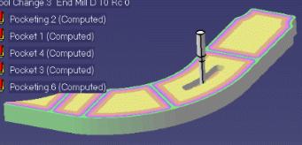
11 3. In the PPR tree, select any manufacturing operation.
12 4. Select the Tool Path Replay icon from the Tool Path Management toolbar. You can also right-click the operation in the PPR tree and select Tool Path Replay from the contextual menu.
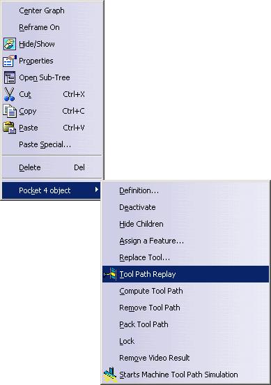
13
14 5. The Replay dialog box appears. Continue working through the basic tasks: Comparing the Machined Stock Part and the Design Part Pick Point Analysis in Video Mode Using Collision Detection in Video Cross-referencing Collision Information Using Run Summary Generation Using Geometric Analysis Using Video Measure Analysis Removing Detached Material in Video Defining Maximum Machining Feed Rate
15 Comparing the Machined Stock Part and the Design Part This procedure describes how to do a comparison between the machined stock and the target (design) part through the graphical comparison functionality in Video. Areas on the machined stock from which extra material has been removed are reported as gouges. Areas where material has not been removed completely are reported as remaining material. This functionality provides a visual comparison achieved by color-coding the stock according to how close the machined surface is to the surface of the target (design) part. A series of tolerance bands and a color for each band is defined. All points on the machined surface that lie within a particular band are given the corresponding band color. By defining the tolerance band appropriately, all remaining material points or gouge points on the machined surface can be identified and displayed in as many colors. The magnitude of remaining material or gouge can also be queried at a specified point. This magnitude is the shortest distance between the picked point on the stock and the nearest point on the target (design) part. The coordinates of the picked point on the stock are also displayed along with the magnitude of remaining material or gouge. Complete the procedures as described in Accessing NC Manufacturing Verification. 1. In the Replay dialog box, select the Full Video icon to simulate the material removal by the machining operation previously selected in the PPR tree. (For more information, see "Video Mode for Material Removal Simulation" in the NC Manufacturing Infrastructure User Guide.) The material removal video is displayed.


16 2. Select the Run button to run the video simulation. You can stop and continue the Video simulation using the buttons marked below. 3. In the Replay dialog box, select the Analyze icon. The Analysis dialog box appears giving details of all errors found. Select the fault type to be analyzed, (Remaining Material, or Gouge) and specify the tolerance for the comparison. The fault filter setting permits two types of faults: Remaining Material and Gouge. Remaining Material: Areas where the tool has left behind material on the workpiece.

17 The default appearance of this tab gives three tolerance bands for analysis. Select the button to access additional options. The values reflected in the Less mode are also reflected in the More mode and vice versa. Less More Gouge: Areas where the tool has removed excess material from the workpiece during a rapid move. Remaining material and gouges will be displayed as colored zones according to the specified tolerances.
 to the design part surface is greater than the specified tolerance.")
18 Use the checkbox to control the window refresh after a view change. 4. Click the Apply button. The machined part is compared with design part based on the specified settings. Any point on the machined surface of the workpiece is considered to be part of a fault if the distance (deviation) to the design part surface is greater than the specified tolerance. Results of the comparison are reflected on the workpiece, based on the extent of severity of the fault and the customized color settings.
19
20 Pick Point Analysis in Video Mode This procedure describes the pick point analysis feature in video mode. Complete the procedures as described in Accessing NC Manufacturing Verification. 1. In the Replay dialog box, select the Full Video command to simulate the material removal by the machining operation previously selected in the PPR tree. (For more information, see "Video Mode for Material Removal Simulation" in the NC Manufacturing Infrastructure User Guide.) The material removal video is displayed. 2. In the Replay dialog box, select the Analyze command, select the fault types to be analyzed, and specify the tolerance for the comparison. Click the apply button in the Analysis dialog box. 3. Pick a point on the machined stock. The Pick Point Information dialog box appears with the following information:

21 The new display fields are Arc radius and Arc center. These fields are displayed only if the picked point is on a circular entity. This information is available at every pick provided that the point picked is a "machined area pick". To get information about errors and deviation at the picked point, you first need to do a design part comparison. Design part comparison will render the stock in a colorcoded manner, depicting deviations from the design part. A subsequent pick will display the deviation value.

22 Using Collision Detection in Video This procedure describes how to use collision detection in video. Video provides a list of collisions that occurred during material removal simulation. You can select collisions from a list and see the exact point of collision. Later, even after exiting the video window, you can cross-reference and use this information regarding the collision to correct your tool path. For more information, see Cross-referencing Collision Information. You have the option of reporting "soft collisions" or ignoring them. To access the Video Collision options, go to Tools->Options->NC Manufacturing->Photo/Video tab. Select "Continue" and "Touch is Collision" (to report soft collisions) in the Video Collision field. If you select the Stop option in the Video Collision field, the simulation will stop during collision and you will be able to continue Video simulation from the stopped point. Complete the procedures as described in Accessing NC Manufacturing Verification. Run the Video mode simulation.

23 1. Select the Video Collision Report command. The Collision Report is generated and the collision list appears in the Fault Selection drop-down field. Click the button in the Collision Report dialog box to see more detailed information.
 Fixture Stock Holder Tool Shank You have the option to display the tool sweep, the sweep transparency, and the collision point, as well as choose the tool")
24 You have the option of choosing the collision filter type. Type options are: All (all the collisions) Fixture Stock Holder Tool Shank You have the option to display the tool sweep, the sweep transparency, and the collision point, as well as choose the tool sweep color. You also have the option to display the tool at the start point, the end point, or make the tool invisible at a collision location.

25 2. Select a collision in the list. The tool reported in the selected collision is shown at the point of collision along with the tool sweep.
26 Cross-referencing Collision Information This procedure describes how to cross-reference collision information using the Tool Path command. Video provides a list of collisions that occurred during material removal simulation. You can cross-reference and use this information regarding the collision to correct your tool path later, even after exiting the video window. Complete the procedures as described in Accessing NC Manufacturing Verification. Run the simulation in Full Video mode. Note: Video simulation must be run at least once to use the crossreferencing functionality. 1. Select the Video Collision Report command. The collision report is generated and the collision list appears in the Fault Selection drop-down field of the Collision Report dialog box.
27 Note this Collision Report dialog box differs from that generated in video mode. This Collision Report dialog box is available only after video simulation is complete. The Current MO check button shows collisions that occurred in the machine operation selected to access the Tool Path Replay dialog box. 2. Close both dialog boxes. 3. Select the Tool Path Replay icon from the Tool Path Management toolbar. OR Right-click the operation in the PPR tree and select Tool Path Replay from the contextual menu.

28 4. In the Replay dialog box, select the Video Collision Report command. The Collision List dialog box appears.


29 5. Select any collision in the Fault selection list. Use the check box to display collisions that have occurred in the current machining operation only. In the 3D view, the tool is positioned at the start point of the selected tool path. Also visible is the tool path segment where the collision occurs. The collision location is indicated by a cross-mark.

30 Using Run Summary Generation This procedure describes the run summary generation feature in Video. After material removal simulation, you have the option of saving the report of the simulation as a text file. The Run Summary report lists the time taken for each operation as well as the time taken for each tool being used for material removal. Complete the procedures as described in Accessing NC Manufacturing Verification. Run the simulation in Video mode. 1. Select the Run Summary Generation icon. 2. Name the text file and save it in the desired location.
31 Run Summary report Amount of time for each operation:
32 Amount of time each tool was used for material removal:
33 Using Geometric Analysis This procedure describes how to use the geometric analysis capabilities for Photo/Video mode. With this functionality, you can geometrically analyze the results of material removal after simulation. This would include: linear distance measure angular measurement between edges and surfaces center and radius measurement of arcs (3-point method) center-to-center distance Complete the procedures as described in Accessing NC Manufacturing Verification. Run the simulation in Video mode. Select the Measure command.
34 The Measure panel appears. Select one of the following commands: Measure Between Measure Item Arc through 3 Points Point Hide/Show Click on OK. The dialog box for the selected command appears. For more information about these commands, please see: Measure Between Measure Item Arc through 3 Points Point Hide/Show

35 Measure Between This procedure describes how to use the Measure Between command. 1. From the Measure dialog box, select the Measure Between command. 2. The Measure Between dialog box appears. By default, measures made on active products are done with respect to the product axis system. Measures made on active parts


36 are done with respect to the part axis system. Note: This distinction is not valid for measures made prior to Version 5 Release 8 Service Pack 1 where all measures are made with respect to the absolute axis system. You can also measure distances and angles with respect to a local V5 axis system. A Keep Measure option in the dialog box lets you keep the current and subsequent measures as features. This is useful if you want to keep the measures as annotations, for example. Defining measure types 3. Select the desired measure type. Notice that the image in the dialog box changes depending on the measure type selected. Between (default): Measures distance and angle between selected items. Chain: Allows you to chain measures with the last selected item becoming the first selection in the next measure.

37 Fan: Fixes the first selection as the reference so that you always measure from this item. Defining Selection 1 and Selection 2 modes 4. Set the desired mode in the Selection 1 and Selection 2 mode dropdown boxes. Any geometry (default mode): Measures distances and angles between defined geometrical entities (points, edges, surfaces, etc.). Note: The Arc center mode is activated in this selection mode. This mode recognizes the axis of cylinders and lets you measure the distance between two cylinder axes, for example. Any geometry, infinite: Measures distances and angles between the infinite geometry (plane or line) on which the selected geometrical entities lie. The Arc center mode is activated and this mode also recognizes cylinder axes. For all other selections, the measure mode is the same as any geometry. Picking point: Measures distances between points selected on defined geometrical entities. Always gives an approximate measure. Point only: Measures distances between points. Dynamic highlighting is limited to points. Edge only: Measures distances and angles between edges and surfaces respectively. Dynamic highlighting is limited to edges or surfaces and is thus simplified compared to the Any
38 geometry mode. All types of edge are supported. Surface only: Measures distances and angles between edges and surfaces respectively. Dynamic highlighting is limited to edges or surfaces and is thus simplified compared to the Any geometry mode. All types of edge are supported. Picking axis: Measures distances and angles between an entity and an infinite line perpendicular to the screen. Simply click to create infinite line perpendicular to the screen. Intersection: Measures distances between intersection points between two edges or an edge and a surface. In this case, two selections are necessary to define selection 1 and selection 2 items. Edge limits: Measures distances between endpoints or midpoints of edges. Endpoints only are proposed on curved surfaces. Arc center: Measures distances between the centers of arcs. Coordinate: Measures distances between coordinates entered for selection 1 and/or selection 2 items. Center of 3 points arc: Measures center-to-center distance between circular entities. Defining the calculation mode 5. Set the desired calculation mode in the Calculation mode dropdown list box. Exact else approximate (default mode): Measures access exact data and wherever possible true values are given. If exact values cannot be measured, approximate values are given (identified by a ~ sign). Exact: Measures access exact data and true values are given. Note that you can only select exact items in the geometry area
39 or specification tree. In certain cases, in particular if products are selected, a warning dialog box informs you that the exact measure could not be made. Approximate: measures are made on tessellated objects and approximate values are given (identified by a ~ sign). Note: You can hide the display of the ~ sign using the Tools -> Options command (General -> Parameters and Measure -> Measure Tools). 6. Click to select a surface, edge or vertex, or an entire product (selection 1). Notes: The appearance of the cursor has changed to reflect the measure command you are in. A number (1 for the selection 1 and 2 for the selection 2) also helps you identify where you are in your measure. Dynamic highlighting as you move your cursor over surfaces, faces and vertices helps you locate items to click on. Customizing your measure You can, at any time, customize the display of the results in both the geometry area and the dialog box. To do so, click Customize... in the Measure Between dialog box and set your display in the Measure Between Customization dialog box. By default, all results are displayed. Point 1 and point 2 give the coordinates of the two points between which the minimum distance is measured.

40 Measuring in a local axis system For this part of the task, you will need a V5 axis system. 7. Click Customize... and check Point 1 and Point 2 options in the Measure Between Customization dialog box. Click OK. 8. Check the Other Axis option in the Measure Between dialog box. 9. Select a V5 axis system in the specification tree of geometry area. 10. Make your measure. This is the same measure made with respect to the absolute axis system:
41 All subsequent measures are made with respect to the selected axis system. To change the axis system, click the Other Axis field and select another axis system. To return to the absolute axis system, uncheck the Other Axis option. This type of measure is associative: if you move the axis system, the measure is impacted and can be updated. 11. Click OK when done.

42 Measure Item This procedure describes how to use the Measure Item command to measure the properties associated to a selected item (points, edges, surfaces and entire products). This command lets you choose the selection mode, the calculation mode and axis system when measuring properties. 1. From the Measure dialog box, select the Measure Item command. 2. The Measure Item dialog box appears. By default, measures made on active products are done with respect to the product axis system. Measures made on active parts are done with respect to the part axis system.
43 Note: This distinction is not valid for measures made prior to Version 5 Release 8 Service Pack 1 where all measures are made with respect to the absolute axis system. You can also measure distances and angles with respect to a local V5 axis system. A Keep Measure option in the dialog box lets you keep the current and subsequent measures as features. This is useful if you want to keep the measures as annotations, for example. Defining the Selection 1 mode 3. Set the desired measure mode in the Selection 1 mode drop-down list. Any geometry (default mode): Measures the properties of the selected item (point, edge, surface, or entire product. Point only: Measures the properties of points. Dynamic highlighting is limited to points. Edge only: Measures the properties of edges. All types of edge are supported. Surface only: Measures the properties of surfaces. For Point only, Edge only, and Surface only modes, dynamic highlighting is limited to points, edges, or surfaces depending on the mode selected and is thus simplified compared to the Any geometry mode. Defining the Calculation mode
44 4. Set the desired calculation mode in the Calculation mode drop down list. Exact else approximate (default mode): Measures access exact data and, wherever possible, true values are given. If exact values cannot be measured, approximate values are given (identified by a ~ sign). Exact: Measures access exact data and true values are given. Note that you can only select exact items in the geometry area or specification tree. In certain cases, in particular if products are selected, a warning dialog box informs you that the exact measure could not be made. Approximate: measures are made on tessellated objects and approximate values are given (identified by a ~ sign). Note: You can hide the display of the ~ sign using the Tools -> Options command (General -> Parameters and Measure -> Measure Tools). 5. In the 3D view, click to select the desired item. Note that the appearance of the cursor has changed to reflect the measure command you are in.

45 The dialog box gives information about the selected item, in our case a surface, and indicates whether the result is an exact or approximate value. The surface area is also displayed in the geometry area. 6. In the Measure Item dialog box, click to see the properties the system can detect for the various types of item you can select. By default, you obtain:

46 Note: The center of gravity of surfaces is visualized by a point. In the case of non-planar surfaces, the center of gravity is attached to the surface over the minimum distance. 7. Set the display of results in both the geometry area and the Measure Item dialog box as follows, then click Apply. The Measure Item dialog box is updated and now gives the surface perimeter. 8. Try selecting other items to measure associated properties. Measuring properties in a local axis system For this part of the task, you will need a V5 axis system. 9. Check the Other Axis option in the Measure Item dialog box. 10. Select a V5 axis system in the specification tree or geometry area.
47 11. Make your measure. All subsequent measures are made with respect to the selected axis system. To change the axis system, click the Other Axis field and select another axis system. To return to the main axis system, uncheck the Other Axis option. This type of measure is associative: if you move the axis system, the measure is impacted and can be updated. 12. Click OK when finished. If you checked the Keep Measure option in the Measure Item dialog box, your measures are kept as features.

48 Arc through 3 Points This procedure describes how to use the Arc through 3 Points command. This command is used to measure the center and radius/diameter of circular entities using accurate point information. To use this command, point visibility must be ON. 1. From the Measure dialog box, select the Arc through 3 Points icon. 2. In the 3D view, select three points in the machined part geometry: the start point, the center point, and the end point. An arc is fitted through the three selected points and the Measure Between dialog box is updated with the length, angle, angle at vertex, and radius or diameter of the arc. Start, end and center point coordinates are also shown.
49

50 Point Hide/Show This procedure describes how to use the Point Hide/Show command. This command disables/enables the display of accurate point geometries present on vertices of the machined part. From the Measure dialog box, select the Point Hide/Show command. The point geometries present on vertices of the machined part are hidden (OFF) or displayed (ON), depending on their current display state. The image below illustrates the points shown.
51 Using Video Measure Analysis This procedure describes how to do measure analysis in the video window without the need to go to the measure window. With this functionality, you can make the following types of measurements: distance and angle between planar surfaces and edges distance and angle between centerlines of circular entities distance and angle between circular entities and planes or edges distances between points and other supported entities Run the Full Video command. In the Replay dialog box, select the Video Measure command. The Video Measure dialog box appears.

52 Select the options "Display vertices" and "Display Edges" to display all the edges and vertices of the solid. The options in both Selection 1 Mode and Selection 2 Mode drop-down menus are: Arc Plane Edge Point These options can selected in any combination. Below are some of the possible selection combinations: Arc/Arc Plane/Plane Arc/Plane or Plane/Arc Measures the distance between two arc center axes. Measures the distance and angle between two planes Measures the distance between an arc center axis and a plane or vice versa.
53 Edge/Edge Point/Point Edge/Arc Edge/Plane Edge/Point Point/Arc Point/Plane Measures the distance and angle between two parallel edges. If they are not parallel, only the angle between them is measured. Measures the distance between two points. The coordinates of both points are also displayed. Measures the distance and angle between an edge and an arc center axis if the edge is parallel to the arc center axis. If they are not parallel, only the angle between them is measured. Measures the distance and angle between an edge and a plane if the edge is parallel to the plane. If they are not parallel, only the angle between them is measured. Measures the shortest distance between an edge and a vertex. The coordinates of the point on the edge from which the minimum distance is calculated is also displayed. Measures the shortest distance between the arc center axis and the vertex. Measures the shortest distance between a point and a plane

54 Removing Detached Material in Video During the material removal process, chunks of material may get detached from the stock. You can pick any of the unconnected material belonging to the stock and delete it after the simulation has been stopped. This functionality eliminates false collisions that occur when unwanted chunks remain after being detached from the stock. 1. In the Replay dialog box, select the Remove Chunks command.

55 The Delete Material dialog box appears. 2. In the 3D view, select the parts to be deleted. The select parts change color. 3. Click OK in the Delete Material dialog box. The unwanted material is deleted.

56 If there are no chunks of material from the stock and the command is invoked, the following error message will appear.
57 Defining Maximum Machining Feedrate This procedure describes how to define maximum machining feedrate for a part operation as well as for a specific machining operation. From the samples directory, open the Processfinal.CATProcess file or you may use your own data. Defining for a part operation 1. In the PPR tree, double-click on Part Operation.1. The Part Operation dialog box appears.

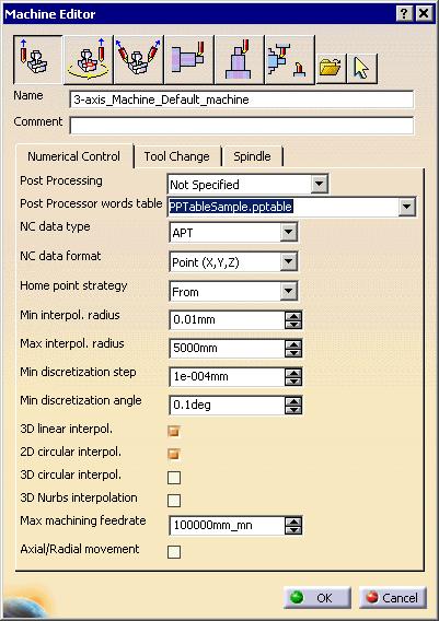
58 2. Click on the Machine icon in the Part Operation dialog box. The Machine Editor dialog box appears.
59


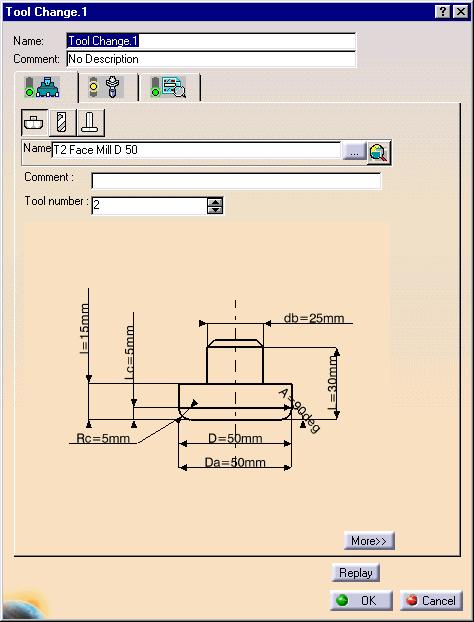
60 3. Input the desired value in the Max machining feedrate field and click on OK. Errors (tool collision with the stock) will be reported if the feedrate exceeds this value. Defining for a specific machining operation 1. In the PPR tree, double-click on Tool Change.1 The following dialog box appears:
61
62 2. In the dialog box, click on the button. The dialog box expands. The maximum machining feedrate can be set in the Feeds & Speeds tab. Errors (tool collision with the stock) will be reported if the feedrate exceeds this value.

63
64 Glossary D DPM Digital Process for Manufacturing G gouge Area where the tool has removed too much material from the workpiece. N NC Numerical control R remaining material Area where the tool has not completely removed material from the workpiece. S stock part Raw material or base part T tool clash Area where the tool collided with the workpiece during a rapid move.
65 Index A analysis geometric pick point arc through 3 points C collision filter collision information, cross-referencing commands Collision Detection Compare Analysis Remove Chunks Video Measure cross-referencing collision information D design part, compare to machined stock part F feedrate, maximum machining filter, collision
66 G geometric analysis M machined part, compare to design part maximum machining feedrate measure types between chain fan measuring circular entities measuring items N NC Manufacturing Verification, accessing P pick point analysis point hide/show functionality R Remove Chunks command
67 S summary, running V Video Measure command
NC Manufacturing Verification
 NC Manufacturing Verification Page 1 Preface Using This Guide Where to Find More Information Conventions What's New? User Tasks Accessing NC Manufacturing Verification Comparing the Machined Stock Part
Prismatic Machining Overview What's New Getting Started User Tasks
 Prismatic Machining Overview Conventions What's New Getting Started Enter the Workbench Create a Pocketing Operation Replay the Toolpath Create a Profile Contouring Operation Create a Drilling Operation
Equipment Support Structures
 Equipment Support Structures Overview Conventions What's New? Getting Started Setting Up Your Session Creating a Simple Structural Frame Creating Non-uniform Columns Creating Plates with Openings Bracing
Tolerance Analysis of Deformable Assembly
 Tolerance Analysis of Deformable Assembly Overview Conventions What's New? Getting Started Entering the Workbench Creating a New Analysis Importing the Assembly Definition Computing a Tolerance Analysis
Fastening Review Overview Basic Tasks DMU Fastening Review Interoperability Workbench Description Customizing Index
 Fastening Review Overview Conventions Basic Tasks Displaying Joined Parts in a Balloon Running the Fastening Rules Analysis Reporting Creating Structural Reports Creating Flat Reports DMU Fastening Review
Equipment Support Structures
 Page 1 Equipment Support Structures Preface Using This Guide Where to Find More Information Conventions What's New? Getting Started Setting Up Your Session Creating a Simple Structural Frame Creating Non-uniform
Electrical 3D Design & Documentation
 Electrical 3D Design & Documentation Page 1 Overview Conventions User Tasks Using Electrical 3D Design & Documentation Entering the Electrical Assembly Design Workbench Entering the Electrical Part Design
DMU Space Analysis Version 5 Release 13. DMU Space Analysis
 Page 1 DMU Space Analysis Preface Using This Guide More Information Conventions What's New? Getting Started Setting Up Your Session Measuring Minimum Distances Sectioning Detecting Clashes Measuring Between
Electrical Harness Installation
 Electrical Harness Installation Page 1 Overview Conventions What's New? Getting Started Entering the Workbench Setting Up the Options Creating a Bundle Segment Document Creating Construction Points Defining
DMU Space Engineering Assistant User Guide
 Page 1 DMU Space Engineering Assistant User Guide Overview Conventions What's New? Getting Started User Tasks Setting Up Your Session Running a Interference Workbench Description DMU Space Engineering
Electrical Harness Flattening
 Electrical Harness Flattening Overview Conventions What's New? Getting Started Accessing the Electrical Harness Flattening Workbench Defining the Harness Flattening Parameters Extracting Data Flattening
DMU Engineering Analysis Review
 Page 1 DMU Engineering Analysis Review Preface Using This Guide Where to Find More Information Conventions What's New? Getting Started Inserting a CATAnalysis Document Using DMU Space Analysis From CATAnalysis
Electrical Wire Routing
 Electrical Wire Routing Page 1 Overview Conventions What's New? Getting Started Accessing the Workbench Creating the Bundle Selecting Systems with External Data Routing Wires from External Data User Tasks
DMU Space Engineering Assistant User Guide
 DMU Space Engineering Assistant User Guide Overview Conventions What's New? Getting Started User Tasks Setting Up Your Session Running an Interference Analysis Workbench Description DMU Space Engineering
Advanced Meshing Tools
 Page 1 Advanced Meshing Tools Preface Using This Guide More Information Conventions What's New? Getting Started Entering the Advanced Meshing Tools Workbench Defining the Surface Mesh Parameters Setting
DMU Engineering Analysis Review
 DMU Engineering Analysis Review Overview Conventions What's New? Getting Started Entering DMU Engineering Analysis Review Workbench Generating an Image Visualizing Extrema Generating a Basic Analysis Report
Electrical Library Version 5 Release 13. Electrical Library
 Electrical Library Page 1 Overview Conventions What's New? Getting Started Entering the Electrical Part Design Workbench Defining a Single Insert Connector Defining a Cavity Connection Point Entering Electrical
DMU Fitting Simulator
 Page 1 DMU Fitting Simulator Preface Using This Guide More Information Conventions What's New? Getting Started Using Tracks Starting a Session Recording a Track Using Automatic Path Finder Using the Smooth
Human Posture Analysis
 Human Posture Analysis Overview Conventions What's New? Getting Started Creating a Manikin User Tasks Using the Posture Editor Selecting or Editing the DOF (Degree of Freedom) Displaying and Editing Angular
Publication Number spse01695
 XpresRoute (tubing) Publication Number spse01695 XpresRoute (tubing) Publication Number spse01695 Proprietary and restricted rights notice This software and related documentation are proprietary to Siemens
Publication Number spse01695
 XpresRoute (tubing) Publication Number spse01695 XpresRoute (tubing) Publication Number spse01695 Proprietary and restricted rights notice This software and related documentation are proprietary to Siemens
Multi-Axis Surface Machining
 CATIA V5 Training Foils Multi-Axis Surface Machining Version 5 Release 19 January 2009 EDU_CAT_EN_MMG_FI_V5R19 1 About this course Objectives of the course Upon completion of this course you will be able
Circuit Board Design Version 5 Release 13. Circuit Board Design
 Circuit Board Design Page 1 Overview Conventions What's New? Getting Started Accessing the Circuit Board Workbench Creating a Board Pocket and Holes Constraint Area Exporting Data Importing Data User Tasks
TRAINING GUIDE LATHE-LESSON-1 FACE, ROUGH, FINISH AND CUTOFF
 TRAINING GUIDE LATHE-LESSON-1 FACE, ROUGH, FINISH AND CUTOFF Mastercam Training Guide Objectives You will create the geometry for Lathe-Lesson-1, and then generate a toolpath to machine the part on a CNC
Structure Preliminary Layout
 Structure Preliminary Layout Overview Conventions What's New? Getting Started Setting Up Your Session Defining the Hull Form Setting Up Your Grid Creating Molded Forms Creating a Compartment Creating Boundaries
Piping Design. Site Map Preface Getting Started Basic Tasks Advanced Tasks Customizing Workbench Description Index
 Piping Design Site Map Preface Getting Started Basic Tasks Advanced Tasks Customizing Workbench Description Index Dassault Systèmes 1994-2001. All rights reserved. Site Map Piping Design member member
Human Posture Analysis
 Human Posture Analysis Page 1 Preface Using This Guide Where to Find More Information Conventions What's New? Getting Started Creating a Manikin User Tasks Using the Posture Editor Segments Degree of Freedom
Electrical System Functional Definition
 Electrical System Functional Definition Preface What's New? Getting Started Basic Tasks Advanced Tasks Workbench Description Customizing Glossary Index Dassault Systèmes 1994-2000. All rights reserved.
TRAINING GUIDE. Sample. Distribution. not for LATHE-LESSON-1 FACE, ROUGH, FINISH AND CUTOFF
 TRAINING GUIDE LATHE-LESSON-1 FACE, ROUGH, FINISH AND CUTOFF Mastercam Training Guide Objectives You will create the geometry for Lathe-Lesson-1, and then generate a toolpath to machine the part on a CNC
Product Structure Version 5 Release 13. Product Structure
 Product Structure Page 1 Site Map Preface Conventions What's New? Basic Tasks Entering the Product Structure Workbench Opening a CATProduct with a Progress Bar Selecting Products only Selecting Modes Inserting
3 AXIS STANDARD CAD. BobCAD-CAM Version 28 Training Workbook 3 Axis Standard CAD
 3 AXIS STANDARD CAD This tutorial explains how to create the CAD model for the Mill 3 Axis Standard demonstration file. The design process includes using the Shape Library and other wireframe functions
DMU Optimizer Overview What's New? Getting Started User Tasks
 DMU Optimizer Overview Conventions What's New? Getting Started Starting a Session Generating a Silhouette Generating a Wrapping Generating a Thickness Generating an Offset Generating a Free Space User
TRAINING GUIDE. Sample not. for Distribution LATHE-LESSON-1 FACE, ROUGH, FINISH AND CUTOFF
 TRAINING GUIDE LATHE-LESSON-1 FACE, ROUGH, FINISH AND CUTOFF Mastercam Training Guide Objectives You will create the geometry for Lathe-Lesson-1, and then generate a toolpath to machine the part on a CNC
Multi-Pockets Machining
 CATIA V5 Training Foils Multi-Pockets Machining Version 5 Release 19 January 2009 EDU_CAT_EN_MPG_FF_V5R19 1 About this course Objectives of the course Upon completion of this course you will be able to
What's New in CAMWorks 2016
 Contents (Click a link below or use the bookmarks on the left) About this Version (CAMWorks 2016 SP3)... 2 Supported Platforms 2 Resolved CPR s document 2 About this Version (CAMWorks 2016 SP2.2) 3 Supported
HVAC Diagrams Preface What's New? Getting Started User Tasks
 HVAC Diagrams Preface Using This Guide What's New? Getting Started Entering the Workbench Setting up Working Units and Grid Placing Components Routing an HVAC Line Placing Components in a Line Repositioning
FreeStyle Shaper & Optimizer
 FreeStyle Shaper & Optimizer Preface What's New Getting Started Basic Tasks Advanced Tasks Workbench Description Customizing Glossary Index Dassault Systèmes 1994-99. All rights reserved. Preface CATIA
Mill Level 1 Training Tutorial
 To order more books: Call 1-800-529-5517 or Visit www.inhousesolutions.com or Contact your Mastercam dealer Mastercam X 5 Copyright: 1998-2010 In-House Solutions Inc. All rights reserved Software: Mastercam
CNC Programming Simplified. EZ-Turn Tutorial.
 CNC Programming Simplified EZ-Turn Tutorial www.ezcam.com Copyright Notice This manual describes software that contains published and unpublished works of authorship proprietary to EZCAM Solutions, Inc.
Knowledge Advisor Overview What's New? Getting Started User Tasks
 Knowledge Advisor Overview Conventions What's New? Getting Started Using Parameters Using Formulas Using Rules Using Checks User Tasks Working with Parameters Creating a Parameter Introducing Parameters
Electrical System Functional Definition
 Electrical System Functional Definition Overview Conventions What's New? Getting Started Creating a New System Creating Equipment Creating Connectors Creating a Signal Connecting Saving Your System User
Structure Preliminary Layout
 Page 1 Structure Preliminary Layout Preface Using This Guide Where to Find More Information What's New? Getting Started Setting Up Your Session Defining the Hull Form Setting Up Your Grid Creating Molded
Aerospace Sheetmetal Design
 Aerospace Sheetmetal Design Page 1 Overview Conventions What's New? Getting Started Entering the Aerospace SheetMetal Design Workbench Defining the Aerospace SheetMetal Parameters Creating a Web from a
StickFont Editor v1.01 User Manual. Copyright 2012 NCPlot Software LLC
 StickFont Editor v1.01 User Manual Copyright 2012 NCPlot Software LLC StickFont Editor Manual Table of Contents Welcome... 1 Registering StickFont Editor... 3 Getting Started... 5 Getting Started...
Knowledge Expert Overview What's New? Getting Started Basic Tasks Advanced Tasks Reference
 Knowledge Expert Overview Conventions What's New? Getting Started Creating an Expert Check Creating an Expert Rule Basic Tasks About RuleBases Storing a Rule Base in a Catalog Using a Rule Base Stored
Shape Sculptor Version 5 Release 13. Shape Sculptor
 Shape Sculptor Page 1 Overview Using This Guide Where to Find More Information What's New? Getting Started Entering the Workbench Importing a Polygonal Mesh Decimating a Polygonal Mesh User Tasks Input
Piping & Instrumentation Diagrams
 Piping & Instrumentation Diagrams Preface Using This Guide What's New? Getting Started Entering the Workbench Setting up Working Units and Grid Placing Components Routing a Piping Line or I & C Loop Placing
Module 1: Basics of Solids Modeling with SolidWorks
 Module 1: Basics of Solids Modeling with SolidWorks Introduction SolidWorks is the state of the art in computer-aided design (CAD). SolidWorks represents an object in a virtual environment just as it exists
SheetMetal Design Version 5 Release 13. SheetMetal Design
 SheetMetal Design Page 1 Overview Conventions What's New? Getting Started Entering the Workbench Defining the Parameters Creating the First Wall Creating the Side Walls Creating a Cutout Creating Automatic
TRAINING GUIDE. Sample Only. not to be used. for training MILL-LESSON-15 CORE ROUGHING, WATERLINE, AND SURFACE FINISH LEFTOVER
 TRAINING GUIDE MILL-LESSON-15 CORE ROUGHING, WATERLINE, AND SURFACE FINISH LEFTOVER Mastercam Training Guide Objectives You will use a provided model for Mill-Lesson-15, then generate the toolpaths to
Piping & Instrumentation Diagrams
 Page 1 Piping & Instrumentation Diagrams Preface Using This Guide What's New? Getting Started Entering the Workbench Setting up Working Units and Grid Placing Components Routing a Piping Line or I & C
What's New in CAMWorks For Solid Edge-2015
 Contents (Click a link below or use the bookmarks on the left) What s New in CAMWorks For Solid Edge 2015-SP0 2 Supported Platforms 2 Resolved CPR s document 2 General... 3 CAMWorks Virtual Machine for
FreeStyle Shaper Optimizer & Profiler
 FreeStyle Shaper Optimizer & Profiler Page 1 Preface Using This Guide More Information What's New? Getting Started Starting the FreeStyle Workbench Creating a First Surface Editing the Surface Creating
TOOLPATHS TRAINING GUIDE. Sample. Distribution. not for MILL-LESSON-4-TOOLPATHS DRILL AND CONTOUR
 TOOLPATHS TRAINING GUIDE MILL-LESSON-4-TOOLPATHS DRILL AND CONTOUR Mill-Lesson-4 Objectives You will generate a toolpath to machine the part on a CNC vertical milling machine. This lesson covers the following
MULTICAx SE Plug-in Overview What's New? User Tasks Customizing Index
 MULTICAx SE Plug-in Overview What's New? User Tasks Requirements Methodologies and Advice Initializing the Environment Importing Data Importing Part Files Interactively 3d com Interoperability:Importing
What's New in CAMWorks 2016
 Contents (Click a link below or use the bookmarks on the left) What s New in CAMWorks 2016 SP0 2 Supported Platforms 2 Resolved CPR s document 2 Improved Tool Management Interactions... 3 Tool tree view
FEM Surface. Preface Getting Started Basic Tasks Glossary Index TOC. Dassault Systèmes All rights reserved.
 TOC FEM Surface Preface Getting Started Basic Tasks Glossary Index Dassault Systèmes 1994-99. All rights reserved. file:////moyenne/users/cma/fmsdoccxr5/fmsenglish/fmsug.doc/src/fmsugtoc.htm [09/26/2000
MULTICAx IGES Plug-in
 MULTICAx IGES Plug-in Overview What's New User Tasks Requirements Methodologies and Advice Initializing the Environment Importing IGES Data Importing Part Files Interactively Translating Files from the
Systems Space Reservation
 Systems Space Reservation Preface Using This Guide What's New? Getting Started Enter the Workbench Create an Equipment Reservation Set Correct Working Units and Grid Changing the Current Axis Saving Documents
Profile Modeler Profile Modeler ( A SuperControl Product )
") Profile Modeler ( A SuperControl Product ) - 1 - Index Overview... 3 Terminology... 3 Launching the Application... 4 File Menu... 4 Loading a File:... 4 To Load Multiple Files:... 4 Clearing Loaded Files:...
Profile Modeler ( A SuperControl Product ) - 1 - Index Overview... 3 Terminology... 3 Launching the Application... 4 File Menu... 4 Loading a File:... 4 To Load Multiple Files:... 4 Clearing Loaded Files:...
ECE415: NX TURNING CAM TUTORIAL
 ECE415: NX TURNING CAM TUTORIAL Liangliang Chen, and Miao Yu Based on the turning tutorial in NX, this tutorial steps you through the process of creating NC codes for a shaft that can run on the machines
MULTICAx STEP Plug-in
 MULTICAx STEP Plug-in Overview What's New User Tasks Requirements Methodologies and Advice Initializing the Environment Importing STEP Data Importing Part Files Interactively Translating Files from the
Mechanical Design V5R19 Update
 CATIA V5 Training Foils Mechanical Design V5R19 Update Version 5 Release 19 August 2008 EDU_CAT_EN_MD2_UF_V5R19 1 About this course Objectives of the course Upon completion of this course you will be able
SolidWorks Implementation Guides. User Interface
 SolidWorks Implementation Guides User Interface Since most 2D CAD and SolidWorks are applications in the Microsoft Windows environment, tool buttons, toolbars, and the general appearance of the windows
1 - Introduction Training Guide Objectives WorkXplore Environment Importing and Opening CAD Files 5
 Table Of Contents 1.1 - Training Guide Objectives Table Of Contents 1 - Introduction 3 1.1 - Training Guide Objectives... 3 1.2 - WorkXplore Environment... 3 2 - Importing and Opening CAD Files 5 2.1 -
4 & 5 Axis Mill Training Tutorials. To order more books: Call or Visit or Contact your Mastercam Dealer
 4 & 5 Axis Mill Training Tutorials To order more books: Call 1-800-529-5517 or Visit www.inhousesolutions.com or Contact your Mastercam Dealer Mastercam X Training Tutorials 4 & 5 Axis Mill Applications
Lesson 4: Surface Re-limitation and Connection
 Lesson 4: Surface Re-limitation and Connection In this lesson you will learn how to limit the surfaces and form connection between the surfaces. Lesson contents: Case Study: Surface Re-limitation and Connection
Chapter 2 Parametric Modeling Fundamentals
 2-1 Chapter 2 Parametric Modeling Fundamentals Create Simple Extruded Solid Models Understand the Basic Parametric Modeling Procedure Create 2-D Sketches Understand the Shape before Size Approach Use the
3D ModelingChapter1: Chapter. Objectives
 Chapter 1 3D ModelingChapter1: The lessons covered in this chapter familiarize you with 3D modeling and how you view your designs as you create them. You also learn the coordinate system and how you can
Intersecting Lamina. To complete this model you should have a working knowledge of Solidworks 2006/2009.
 Prerequisite knowledge Focus of lesson Problem To complete this model you should have a working knowledge of Solidworks 2006/2009. This lesson focuses on using SolidWorks to solve a geometrical problem.
User Guide. mk Config
 User Guide mk Config mk Config Register 1.1. CD-Start 4 1.2. Installation 5 1.3. Start 6 1.4. Layout of user interface and functions 7 1.4.1. Overview 7 1.4.2. Part buttons 8 1.4.3. Menus 9 1.4.3.1. Export
CATIA Electrical Space Reservation TABLE OF CONTENTS
 TABLE OF CONTENTS Introduction...1 Manual Format...2 Electrical Reservations...3 Equipment Reservations...5 Pathway Reservations...31 Advanced Reservations...49 Reservation Analysis...67 Clash...69 Sectioning...73
EZ-Mill EXPRESS TUTORIAL 2. Release 13.0
 E-Mill EPRESS TUTORIAL 2 Release 13.0 Copyright Notice This manual describes software that contains published and unpublished works of authorship proprietary to ECAM Solutions, Inc. It is made available
MULTICAx PD Plug-in Overview What's New? User Tasks Customizing Glossary Index
 MULTICAx PD Plug-in Overview What's New? User Tasks Requirements Methodologies and Advice Initializing the Environment Initializing the Environment for Indirect Mode Initializing the Environment for Direct
CHAPTER 1: SOLIDWORKS 2008 USER INTERFACE
 CHAPTER 1: SOLIDWORKS 2008 USER INTERFACE Chapter Objective SolidWorks is a design software application used to model and create 2D and 3D sketches, 3D parts and assemblies, and 2D drawings. Chapter 1
CNC Programming Simplified. EZ-Turn / TurnMill Tutorial.
 CNC Programming Simplified EZ-Turn / TurnMill Tutorial www.ezcam.com Copyright Notice This manual describes software that contains published and unpublished works of authorship proprietary to EZCAM Solutions,
CATIA V5 Training Foils
 CATIA V5 Training Foils Prismatic Machining Version 5 Release 19 January 2009 EDU_CAT_EN_PMG_FF_V5R19 1 About this course Objectives of the course Upon completion of this course you will be able to: -
Inventor 201. Work Planes, Features & Constraints: Advanced part features and constraints
 Work Planes, Features & Constraints: 1. Select the Work Plane feature tool, move the cursor to the rim of the base so that inside and outside edges are highlighted and click once on the bottom rim of the
Lesson 14 Blends. For Resources go to > click on the Creo Parametric Book cover
 Lesson 14 Blends Figure 14.1 Cap OBJECTIVES Create a Parallel Blend feature Use the Shell Tool Create a Swept Blend REFERENCES AND RESOURCES For Resources go to www.cad-resources.com > click on the Creo
Tutorial 7 Finite Element Groundwater Seepage. Steady state seepage analysis Groundwater analysis mode Slope stability analysis
 Tutorial 7 Finite Element Groundwater Seepage Steady state seepage analysis Groundwater analysis mode Slope stability analysis Introduction Within the Slide program, Slide has the capability to carry out
Training Guide Getting Started with WorkXplore 3D
 Training Guide Getting Started with WorkXplore 3D Table of Contents Table of Contents 1 Training Guide Objectives 1-1 2 WorkXplore 3D Environment 2-1 3 Importing and Opening CAD Files 3-1 3.1 Importing
Electrical Cableway Routing
 Electrical Cableway Routing Preface Using This Guide What's New? Getting Started Entering the Workbench Placing a Hanger Routing a Loft Through Hangers Placing a Conduit on a Run Saving Documents Updating
Skateboard. Hanger. in the Feature Manager and click Sketch on the Context toolbar, Fig. 1. Fig. 2
 Chapter 3 Skateboard Hanger A. Sketch1 Lines. Step 1. Click File Menu > New, click Part Metric and OK. Step 2. Click Right Plane in the Feature Manager and click Sketch on the Context toolbar, Fig. 1.
Structural & Thermal Analysis Using the ANSYS Workbench Release 12.1 Environment
 ANSYS Workbench Tutorial Structural & Thermal Analysis Using the ANSYS Workbench Release 12.1 Environment Kent L. Lawrence Mechanical and Aerospace Engineering University of Texas at Arlington SDC PUBLICATIONS
Lesson 3: Surface Creation
 Lesson 3: Surface Creation In this lesson, you will learn how to create surfaces from wireframes. Lesson Contents: Case Study: Surface Creation Design Intent Stages in the Process Choice of Surface Sweeping
v. 9.1 GMS 9.1 Tutorial UTEXAS Embankment On Soft Clay Introduction to the UTEXAS interface in GMS for a simple embankment analysis
 v. 9.1 GMS 9.1 Tutorial UTEXAS Embankment On Soft Clay Introduction to the UTEXAS interface in GMS for a simple embankment analysis Objectives Learn how to build a simple UTEXAS model in GMS. Prerequisite
Lesson 14 Blends. For Resources go to > click on the Creo Parametric 2.0 Book cover
 Lesson 14 Blends Figure 14.1 Cap OBJECTIVES Create a Parallel Blend feature Use the Shell Tool Create a Hole Pattern REFERENCES AND RESOURCES For Resources go to www.cad-resources.com > click on the Creo
MULTICAx SolidWorks Plug-in
 MULTICAx SolidWorks Plug-in Overview What's New? User Tasks Requirements Methodologies and Advice Initializing the Environment Importing SolidWorks Data Importing Part Files or Assembly Files Interactively
전산응용설계 (Computer Aided Design)
") 전산응용설계 (Computer Aided Design) CATIA (Computer Aided Three dimensional Interactive Application) 기계자동차공학부자동차공학전공 Chapter 3. CATIA 기초 학습내용 : 객체선택 (Selecting Objects) 객체감추기와보이기 (Hiding and Showing objects)
전산응용설계 (Computer Aided Design) CATIA (Computer Aided Three dimensional Interactive Application) 기계자동차공학부자동차공학전공 Chapter 3. CATIA 기초 학습내용 : 객체선택 (Selecting Objects) 객체감추기와보이기 (Hiding and Showing objects)
Basic Modeling 1 Tekla Structures 12.0 Basic Training September 19, 2006
 Tekla Structures 12.0 Basic Training September 19, 2006 Copyright 2006 Tekla Corporation Contents Contents 3 1 5 1.1 Start Tekla Structures 6 1.2 Create a New Model BasicModel1 7 1.3 Create Grids 10 1.4
SOLIDWORKS 2018 Reference Guide
 SOLIDWORKS 2018 Reference Guide A comprehensive reference guide with over 250 standalone tutorials David C. Planchard, CSWP, SOLIDWORKS Accredited Educator SDC PUBLICATIONS Better Textbooks. Lower Prices.
Modeling a Gear Standard Tools, Surface Tools Solid Tool View, Trackball, Show-Hide Snaps Window 1-1
 Modeling a Gear This tutorial describes how to create a toothed gear. It combines using wireframe, solid, and surface modeling together to create a part. The model was created in standard units. To begin,
Solidworks 2006 Surface-modeling
 Solidworks 2006 Surface-modeling (Tutorial 2-Mouse) Surface-modeling Solid-modeling A- 1 Assembly Design Design with a Master Model Surface-modeling Tutorial 2A Import 2D outline drawing into Solidworks2006
1 - Introduction Training Guide Objectives WorkXplore Environment Importing and Opening CAD Files 5
 Table Of Contents 1.1 - Training Guide Objectives Table Of Contents 1 - Introduction 3 1.1 - Training Guide Objectives... 3 1.2 - WorkXplore Environment... 3 2 - Importing and Opening CAD Files 5 2.1 -
Fixed Perimeter Rectangles Geometry Creating a Document
 Activity Overview: This activity provides the steps to create a TI-Nspire document that will be used to investigate side length and area in a rectangle with a fixed perimeter. An algebraic approach is
Training Guide CAM Basic 1 Getting Started with WorkNC
 Training Guide CAM Basic 1 Getting Started with WorkNC Table of Contents Table of Contents 1 Training Guide Objectives 1-1 2 Introduction 2-1 2.1 Part Geometry Preparation 2-1 2.2 Starting WorkNC 2-2
Learning the Pro/ENGINEER Interface
 2 Learning the Pro/ENGINEER Interface This chapter introduces the Pro/ENGINEER interface tools: the menus, the dashboards, the selection tools and the viewing controls. As you go through this chapter,
Jewelry Box Lid. A. Sketch Lid Circle. Step 1. If necessary start a new Mastercam file, click FILE Menu > New. Fig. 3
 Mastercam X9 Chapter 39 Jewelry Box Lid A. Sketch Lid Circle. Step 1. If necessary start a new Mastercam file, click FILE Menu > New. Step 2. Click CREATE Menu > Arc > Circle Center Point. Step 3. Key-in
GDL Toolbox 2 Reference Manual
 Reference Manual Archi-data Ltd. Copyright 2002. New Features Reference Manual New Save GDL command Selected GDL Toolbox elements can be exported into simple GDL scripts. During the export process, the
Exercise Guide. Published: August MecSoft Corpotation
 VisualCAD Exercise Guide Published: August 2018 MecSoft Corpotation Copyright 1998-2018 VisualCAD 2018 Exercise Guide by Mecsoft Corporation User Notes: Contents 2 Table of Contents About this Guide 4