Tolerance Analysis of Deformable Assembly
|
|
|
- Tamsyn Anthony
- 6 years ago
- Views:
Transcription
1 Tolerance Analysis of Deformable Assembly Overview Conventions What's New? Getting Started Entering the Workbench Creating a New Analysis Importing the Assembly Definition Computing a Tolerance Analysis Visualizing a Tolerance Analysis Modifying the Assembly Creating Rigid Supports Creating Mechanical Joints Creating Positioning Systems Creating Spots Welding Creating Contacts Creating a Correlated Deviation Creating an Annotation Bag Adding New Activities Linking New Activities Assigning Items to Activities Computing a New Tolerance Analysis Visualizing the New Tolerance Analysis User Tasks Creating a New Tolerance Analysis Defining a Tolerance Analysis Assembly Importing Meshes Importing Tolerance Analysis Data Creating Tolerance Analysis Elements Creating a Rigid Support Creating a Flexible Support Creating a Mechanical Joint Creating a Positioning System Creating Fastening Elements Creating a Contact Linking Contacts Setting Parameters as Default Defining Tolerancing Creating a Deviation Creating a Correlated Deviation Creating a Distance Between Two Points
2 Creating Analysis Geometric Variations Creating Annotation Bags Defining an Assembly Process Adding an Activity Linking Activities Managing Items Tolerance Analysis Reporting Tolerance Analysis Elements Computing a Tolerance Analysis Visualizing Tolerance Analysis Results Displaying Tolerance Analysis Results Editing Tolerance Analysis Images Saving Tolerance Analysis Documents Exporting Data Handling Inconsistent Model Set Up Rigid-Body Motion Singularity Restitution Over-Constrained Singularity Restitution Meshing Connection Error Workbench Description Tolerance Analysis of Deformable Assembly Menu Bar Insert Supports Menu Insert Fastening Elements Menu Insert Contacts Menu Insert Annotations Menu Insert Activities Menu Tools Computed Results Menu Analysis Toolbar Elements Toolbar Process Toolbar Tools Toolbar Customizing General Fastening Tolerancing Cache Management for Tolerancing Analysis of Deformable Assembly Displaying the Tolerancing Analysis of Deformable Assembly's Applicative Data Disabling the Computation Data Clearing Reference Information Transparent Tolerance Analysis Interpreting the Structural Behavior of Product Components Interpreting Annotation Tolerances Interpreting Datum Reference Frames Tolerance Analysis Data Structure File Header Tolerance Analysis Assembly Tolerance Analysis Resources Tolerance Analysis Elements Assembly Process File Footer
3 Measurement Data Statistic Laws Normal Law Uniform Law Constant Law Pearson Law Poisson Law Snedecor Law Interface Description Image Edition Advanced Edition for Images and Local Sensors Glossary Index
4 Overview Welcome to the Tolerance Analysis of Deformable Assembly User's Guide! This guide is intended for users who need to become quickly familiar with the product. This overview provides the following information: Tolerance Analysis of Deformable Assembly in a Nutshell Before Reading this Guide Getting the Most Out of this Guide Accessing Sample Documents Conventions Used in this Guide Tolerance Analysis of Deformable Assembly in a Nutshell Tolerance Analysis of Deformable Assembly product makes it possible to define and analyze the assembly process of components. This application offers a highly productive tolerance analysis of assembly processes with multiple visualizations and analyses for each of them. The information contained in this guide is specific to the Tolerance Analysis of Deformable Assembly workbench. This product is compliant with the Cache Management option set off only, also known as Design Mode. This product is dedicated to analyzing assembly components as V4 model documents containing a mesh, mesh compatible or incompatible with them or with resources may be analyzed, or V5 surfacic part documents where external view and material are specified. Functional Tolerancing & Annotation specifications on V5 shape part documents may be taken into account through an interpretation of tolerances, see Tolerancing options. This product allows you now to analyze assembly components as V5 solid part documents, but in this particular case, their Functional Tolerancing & Annotation specifications are not taken into account. This product is able to read and save V5 process documents based on P.P.R. (Process, Product, Resources) structure and P.P.R. Hub structure. The Processes List contains processes made of assembly activities: Positioning. Fastening. Already done fastening. Release. The Products List contains: The assembly components.
5 The parts which contain reference points for tolerance analysis features between assembly components. The Resources List contains: The supports as assembly on tooling. The parts which contains reference points for tolerance analysis features between an assembly component and its supports. Before Reading this Guide Before reading this guide, you should be familiar with basic Version 5 concepts such as document windows, standard and view toolbars. Therefore, we recommend that you read the Infrastructure User's Guide that describes generic capabilities common to all Version 5 products. It also describes the general layout of V5 and the interoperability between workbenches. You may also like to read the following complementary product guides, for which the appropriate license is required: Product Structure Part Design Assembly Design Generative Shape Design Generative Structural Analysis Functional Tolerancing & Annotations Getting the Most Out of this Guide To get the most out of this guide, we suggest that you start reading and performing the step-by-step Getting Started tutorial. Once you have finished, you should move on to the User Tasks section, which deals with handling all the product functions. The Workbench Description section, which describes the Assembly Design workbench, and the Customizing section, which explains how to set up the options, will also certainly prove useful. Navigating in the Split View mode is recommended. This mode offers a framed layout allowing direct access from the table of contents to the information. Accessing Sample Documents
6 To perform the scenarios, sample documents are provided all along this documentation. For more information about this, refer to Accessing Sample Documents in the Infrastructure User's Guide.
7 Conventions Certain conventions are used in CATIA, ENOVIA & DELMIA documentation to help you recognize and understand important concepts and specifications. Graphic Conventions The three categories of graphic conventions used are as follows: Graphic conventions structuring the tasks Graphic conventions indicating the configuration required Graphic conventions used in the table of contents Graphic Conventions Structuring the Tasks Graphic conventions structuring the tasks are denoted as follows: This icon... Identifies... estimated time to accomplish a task a target of a task the prerequisites the start of the scenario a tip a warning information basic concepts methodology reference information information regarding settings, customization, etc. the end of a task
8 functionalities that are new or enhanced with this release allows you to switch back to the full-window viewing mode Graphic Conventions Indicating the Configuration Required Graphic conventions indicating the configuration required are denoted as follows: This icon... Indicates functions that are... specific to the P1 configuration specific to the P2 configuration specific to the P3 configuration Graphic Conventions Used in the Table of Contents Graphic conventions used in the table of contents are denoted as follows: This icon... Gives access to... Site Map Split View mode What's New? Overview Getting Started Basic Tasks User Tasks or the Advanced Tasks Workbench Description Customizing Reference Methodology Glossary Index
9 Text Conventions The following text conventions are used: The titles of CATIA, ENOVIA and DELMIA documents appear in this manner throughout the text. File -> New identifies the commands to be used. Enhancements are identified by a blue-colored background on the text. How to Use the Mouse The use of the mouse differs according to the type of action you need to perform. Use this mouse button... Whenever you read... Select (menus, commands, geometry in graphics area,...) Click (icons, dialog box buttons, tabs, selection of a location in the document window,...) Double-click Shift-click Ctrl-click Check (check boxes) Drag Drag and drop (icons onto objects, objects onto objects) Drag Move Right-click (to select contextual menu)
10 Enhanced Functionalities What's New? Editing Tolerance Analysis Images The Image Edition dialog box has been modified and new options have been added.
11 Getting Started Before we discuss the detailed instructions for using the Tolerance Analysis of Deformable Assembly workbench, the following scenario aims at giving you a feel for what you can do with a Compliant Assembly. You just need to follow the instructions as you progress. The Getting Started section is composed of the following tasks: This scenario should take about 30 minutes to complete.

12 Entering the Workbench This first task shows you how to enter the Tolerance Analysis of Deformable Assembly workbench. 1. Select Start -> Analysis & Simulation -> Tolerance Analysis of Deformable Assembly command to launch the workbench. The Tolerance Analysis of Deformable Assembly workbench is opened and an empty CATProcess document opens.
13 Creating a New Analysis This task will show you how to create a new analysis. 1. Click the New Analysis icon: 2. Select the Process process in the specification tree. The Tolerance Analysis of Deformable Assembly objects list appears in the specification tree.

14
15 Importing Tolerance Analysis Data This task will show you how to import tolerance analysis data. Make sure that the following documents are in the same folder: TaaData02.txt PlateOne.CATPart PlateTwo.CATPart CurvedPlate.CATPart 1. Click the Import Data icon: 2. Select the TaaData02.txt file in the Open dialog box and click OK. The Import Tolerance Analysis Data window appears while the data is being loaded. The tolerance analysis data is loaded. The data contained in this document is: Assembly process.

16 Components defining the assembly. The tolerance analysis resources.


17 Tolerancing elements: Supports. Mechanical joints. Positioning systems. Fastenings. Contacts. Annotations. Annotation bags. The assembly to be analyzed looks like this.
18
19 Computing a Tolerance Analysis This task will show you how to compute a tolerance analysis activity. 1. Click the Compute icon: The Compute dialog box appears. 2. Select the Release.1 activity in the process list.
20 3. Click OK. The Computation progress bar appears while the tolerance analysis is being computed. The Release.1 activity is computed. The previous activities of the selected activity are computed too. Computed results are not visible. Contact links are created.
21 Visualizing a Tolerance Analysis This task will show you how to visualize tolerance analysis activities. 1. Click the Visualization icon: The Visualization Definition dialog box appears. 2. Click on the Release.1 activity in the process list to visualize it.
22 3. Select View -> Render Style -> Customize View. The Custom View Modes dialog box appears. 4. Select the options as displayed in the Custom View Modes dialog box and click OK. 5. Click the Visualization icon:
23 The assembly looks like this: Assembly components after computation appear with their deformations. The Translational displacement magnitude tool displays the deformations scale.


24 6. Click on the Plate One component to visualize its input tolerances. Input tolerances are visualized. 7. Click on the Release.1 activity to visualize it again.
25 You can visualize any activity previous the selected only. 8. Click OK.
26 Modifying the Assembly This task will show you how to modify the assembly, add a new component and modify the TasResources component. 1. Select Edit -> Links In the Links window, double-click TaaRootProduct: the TaaRootProduct product document is opened in a new window. 3. In the product document, right-click TaaRootProduct, select Components -> Existing Component from the contextual menu and then select the PlateTwo.CATPart document. 4. Close the TaaRootProduct product document. Note: it is not mandatory to save this document at this stage. 5. Back to the P.P.R. document. 6. Double-click the Plate Two part document in the Product List to swap to any Part documentbased workbench.


27 7. Copy the Support Points open body. 8. Paste it in the TaaResources part in the Resources List.


28 9. Right-click the copy and select the Hide/Show command from the contextual menu. 10. Double-click Process in the Process List to return to the Tolerance Analysis of Deformable Assembly workbench.
29 Creating Rigid Supports This task will show you how to create rigid supports. Supports represent the assembly on tooling. Two kinds of supports are available: rigid or flexible. 1. Click the Rigid Support icon: 2. Select the TasResources product resource from which the support will be created. The Rigid Support Definition dialog box appears. 3. Select the Support Points open body.

30 All the points of the open body are selected. In this case, six points. 4. Click OK.
31 Six Rigid Support.13 items are created according to the selected points.
32 Creating Mechanical Joints This task will show you how to create mechanical joints. 1. Click the Mechanical Joint icon: 2. Select the Plate Two assembly component as the first element that will be used to create the mechanical joint. The Mechanical Joint Definition dialog box appears.
33 3. Select Spherical in the Type combo and check the Set parameters as default option. 4. Select the Rigid Support.13.1 support as the second component that will be used to create the mechanical joint.
34 5. Click OK. Mechanical Joint.13 is created.
35 6. Click the Mechanical Joint icon: 7. Select the Rigid Support.13.2 support. 8. Click OK. 9. Repeat steps 6 to 8 with the Rigid Support.13.3 to Rigid Support.13.6 supports. The mechanical joints Mechanical Joint.14 to Mechanical Joint.18 are created.
36

37 Creating Positioning Systems This task will show you how to create positioning systems. 1. Click the Positioning System icon: The Positioning System Definition dialog box appears. 2. Select Mechanical Joint.13 to Mechanical Joint.18 in the specification tree.

38 3. Click OK.

39 The Positioning System.5 is created. 4. Repeat steps 1 to 3 this time, selecting Mechanical Joint.13, Mechanical Joint.14, Mechanical Joint.15. Positioning System.6 is created.
40 Creating Spots Welding This task will show you how to create spots welding. 1. Click the Spot Welding icon: 2. Select Plate Two as the first assembly component that will be used to create the spot welding. The Spot Welding Definition dialog box appears.
41 3. Select Plate One as the second assembly component to be used to create the spot welding. 4. Set the Diameter option to 5 mm. 5. On Plate Two, select the Fastening Points open body where the spots welding will be created.
42 When more than one point is specified, normal directions are computed for each point as being normal to the first component surface on specified points. 6. Click OK. The Spot Welding.4.1 to Spot Welding.4.3 items are created.
43 Creating Contacts This task will show you how to create a contact. 1. Click the Contact icon: 2. Select the Plate Two assembly component as the first element that will be used to create the contact. The Contact Definition dialog box appears.

44 3. Select the Plate One assembly component as the second element that will be used to create the contact. 4. On Plate Two, select the Contact Points open body where the contacts will be created.


45 5. Click OK. Contact.2 is created.
46 Creating a Correlated Deviation This task will show you how to create an input correlated deviation annotation on an assembly component. 1. Click the Correlated Deviation icon: 2. Select the Plate Two assembly component where the annotation will be created. The Correlated Deviation Definition dialog box appears.
47 3. Select Positioning System.6 as the deviation's positioning system.
48 4. Select the Deviation Points open body on Plate Two where the annotation will be created.
49

50 When no measures file is specified in the Statistics Law field, each point of the correlated deviation are created according to a normal law with a mean of 1mm and a standard deviation of 0.1mm. 5. Click OK. Annotation Set.1, Deviations and Deviation Correlated.1 are created.
51
52 Creating an Annotation Bag This task will show you how to create an annotation bag from another one. 1. Click the Annotation Bag icon: 2. Select Deviation.1 to Deviation.4 in TolerancingBag.1. The Annotation Bag Definition dialog box appears.

53 3. Click OK. Annotation Bag.2 is created.
54 Adding New Activities This task will show you how to create new activities describing the assembly process of the Plate Two part: Positioning of the part. Fastening of the part. Release of the assembly. 1. Click the Positioning Activity icon: 2. Select the Process process. The Positioning.2 activity is created.
55 3. Click the Fastening Activity icon: 4. Select the Process process. The Fastening.4 activity is created.
56 5. Click the Release Activity icon: 6. Select the Process process. The Release.2 activity is created.
57 Adding new activities does not create process links.
58 Linking New Activities This task will show you how to create links between new and existing activities. 1. Click the Open PERT Chart icon: 2. Select the Process process. The Process PERT Chart window is opened. It displays process activities and their links.


59 3. Right-click the link between Release.1 and Stop.1 and select the Delete command from the contextual menu.

60 The link is deleted. 4. Drag and drop Positioning.2, Fastening.4, Release.2 and Stop.1 activities.

61 5. Click the Link between activities icon: 6. Select, in the following order, the Release.1, Positioning.2, Fastening.4, Release.2 and Stop.1 activities. New activities are linked.
62 7. Close the Process PERT Chart window. New activities are linked in the specification tree too.
63 Assigning Items to Activities This task will show you how to assign items to process activities. 1. Click the Item Assignment icon: 2. Select the Positioning.2 and Fastening.4 activities. 3. Select the PositionSys.1 positioning system.

64 The PositionSys.1 positioning system is assigned to the Positioning.2 and Fastening.4 activities. 4. Re-click the Item Assignment icon: 5. Select the Positioning.2 and Fastening.4 activities.

65 6. Select the Positioning System.5 positioning system. The Positioning System.5 positioning system is assigned to the Positioning.2 and Fastening.4 activities.
66 7. Re-click the Item Assignment icon: 8. Select the Release.2 activity.
67 9. Select the Positioning System.6 positioning system. The Positioning System.6 positioning system is assigned to Release.2 activity.
68 10. Re-click the Item Assignment icon: 11. Select the Positioning.2, Fastening.4 and Release.2 activities.
69 12. Select the TolerancingBag.1 tolerancing bag. The TolerancingBag.1 tolerancing bag is assigned to the Positioning.2, Fastening.4 and Release.2 activities.
70 13. Re-click the Item Assignment icon: 14. Select the SpotWelding.4.1, SpotWelding.4.2, SpotWelding.4.3 spots welding.
71 15. Select the Fastening.4 activity. The SpotWelding.4.1, SpotWelding.4.2, SpotWelding.4.3 spots welding are assigned to the Fastening.4 activity.
72
73 Computing a New Tolerance Analysis This task will show you how to compute a new tolerance analysis from an added activity. 1. Click the Compute icon: The Compute dialog box appears. 2. Select the Release.2 activity in the process list.
74 3. Click OK. The Computation progress bar appears during the computation process. The Release.2 activity is computed. The previous activities of the selected activity are computed too. Nothing is visible after computing. New contact links are created.
75 Visualizing the New Tolerance Analysis This task will show you how to visualize tolerance analysis activities. 1. Click the Visualization icon: The Visualization dialog box appears. 2. Click on the Release.2 activity in the process list to visualize it.
76 The assembly looks like this: Assembly components after computation appear with their deformations. The Translational displacement magnitude tool displays the deformations scale.

77
78 User Tasks The basic tasks you will perform in the Tolerance Analysis workbench mainly deal with the creation of features you will use to define your toleranced assembly. This section will explain and illustrate how to create these features. The information you will find is listed below:
79 Creating a New Tolerance Analysis This task will show you how to create a new analysis of assembly tolerance. An analysis associates the product structure of an assembly document and its component tolerances according to an assembly process. The analysis uses the PPR (Processes, Products, Resources) workbench structure: The Process list contains assembly processes or other processes containing tolerance analysis activities. See Defining an Assembly Process. The Product list contains imported or created assemblies. Assembly components must contain a mesh to be analyzed. The Resources list contains geometrical elements used to define the assembly on tooling. 1. Click the New Analysis icon: 2. Select the process in the specification tree.
80 The Tolerance Analysis of Deformable Assembly objects list appears in the specification tree: Analysis Manager contains the list of tolerance analyses. Supports contains the list of assembly support. Mechanical Joints contains the list of assembly mechanical joint. Positioning Systems contains the list of assembly positioning systems. Fastening Elements contains the list of assembly fastening elements. Contacts contains the list of assembly contact. Contact Links contains the list of assembly contact links. Annotations Bags contains the list of assembly annotations bags.
81 Defining a Tolerance Analysis Assembly There are two ways to define a tolerance analysis assembly: by importing its components then adding tolerance analysis features, or importing tolerance analysis data which may contain components, tolerance analysis features, assembly processes. Import a Mesh: Click this icon, select one or several components. Import Data: Click this icon, select the data file. See Tolerance Analysis Data Structure for data file structure.

82 Importing Meshes This task will show you how to import a meshed assembly component. This component must be a mesh contained in a CATIA V4 model. Open the BasicTaaProcess1.CATProcess document. The tolerance analysis document looks like this. 1. Click the Import Mesh icon: A product document is added to the product list.

83 2. Select Product.1 as the product where the new component will be imported: 3. Select the Plate.model and CurvedPlate.model documents from the samples\basictaa1 folder in the Open File dialog box and click OK. Three documents are created: The mesh contained in model document is extracted and stored into a CATAnalysis document. Computations are stored into a CATAnalysisComputations document. Results are stored into a CATAnalysisResults document.
84 Importing Tolerance Analysis Data This task will show you how to import tolerance analysis data. Depending on the data file content, you may import: Assembly Assembly + Resources Assembly + Resources + Analysis elements Assembly + Resources + Analysis elements + Assembly process See Tolerance Analysis Data reference for further details. Make sure that the following documents are in the same folder: TaaData02.txt PlateOne.CATPart PlateTwo.CATPart CurvedPlate.CATPart 1. Click the Import Data icon: 2. Select the TaaData02.txt file in the Open dialog box and click OK. The Import Tolerance Analysis Data dialog box appears during the loading process. The tolerance analysis data is loaded. It consists of the following:

85 The assembly process. See Defining Assembly Process. The components defining the assembly.

86 Assembly components may be V5 documents (CATPart, CATProduct) or V4 documents (model). The tolerance analysis resources. Analysis elements: Supports. Mechanical joints. Positioning systems. Fastenings. Contacts. Annotations. Annotation bags.

87 See Creating Tolerance Analysis Elements. The assembly to be analyzed looks like this:
88 Creating Tolerance Analysis Elements Tolerance analysis elements define the assembly components behavior between the user and the assembly on tooling. Create a Rigid Support: Click this icon, select the component, select the point to define a rigid support. Create a Flexible Support: Click this icon, select the component, select the set of points to define a flexible support. Create a Mechanical Joint: Click this icon, select the two components or the component and its support, select the point to define a mechanical joint, choose the joint type. Create a Positioning System: Click this icon, select a set of mechanical joints, modify or not the joint type definition. Create a Fastening Element: Click this icon, select a set of components, select the point to define a spot welding. Create a Fastening Element: Click this icon, select a set of components, select the point to define a riveting. Create a Fastening Element: Click this icon, select a set of components, select the point to define a bolting. Create a Fastening Element: Click this icon, select a set of components, select the point to define a spot gluing. Create a Contact: Click this icon, select two components, select the point to define a contact. Linking Contacts: Click this icon, select two components, select the point to define a contact. Set Parameters as Default
89 Creating a Rigid Support This task will show you how to create a rigid support. A rigid support represents the assembly on tooling and it is modelized by a point which mechanical rigidity is infinite. It is not possible to re-use a point already used as a support (rigid or flexible). This point may be: One, several or all the V5 Points from one or several V5 Open Body. One or several V4 mesh nodes from one or several V4 meshes. A rigid support does not move during the assembly process. The rigid support is stored in a CATPart document of the resource list. Open the BasicTaaProcess2.CATProcess document. 1. Click the Rigid Support icon: 2. Select the component representing the tooling under the ResourcesList node of the PPR tree. If the ResourcesList node of the PPR tree is empty, a resource product structure will be automatically created so that the user can select a resource component. The support created will be linked to the component selected. The Rigid Support Definition dialog box appears.

90 3. Select the Support Points 2 open body. All the points of the open body are selected. In this example six points. 4. Click OK.

91 Three Rigid Support.20 items are created according to the selected points.

92 Creating a Flexible Support This task will show you how to create a flexible support. A flexible support represents the assembly on tooling and it is modelized by points which mechanical rigidity between us can be quantified. Selecting one point is equivalent to creating a rigid support. It is not possible to re-use a point already used as support (rigid or flexible). These points may be: Several or all the V5 Points from one or several V5 Open Body. Several V4 mesh nodes from one or several V4 meshes. A flexible support can move during the assembly and the analysis. The flexible support is stored in a CATPart document of the resource list. Open the BasicTaaProcess2.CATProcess document. 1. Click the Flexible Support icon: 2. Select the TasResources product resource from which the support will be created. The Flexible Support Definition dialog box appears.

93 Three types of flexible supports may be defined: User define For each beam, you must define: Circular Kx: compression stiffness along x axis of the beam. Ky: flexion stiffness along y axis of the beam. Kz: flexion stiffness along z axis of the beam. Kt: torsion stiffness around x axis of the beam DZx: normal direction of the beam along x axis of the part. DZy: normal direction of the beam along y axis of the part. DZz: normal direction of the beam along z axis of the part. For each beam, you must define: Rectangular Radius: radius of the beam. Young Module Poisson Coefficient For each beam, you must define: Base: rectangular base of the beam. Height: rectangular height of the beam. DZx: normal direction of the beam along x axis of the part. DZy: normal direction of the beam along y axis of the part. DZz: normal direction of the beam along z axis of the part. Young Module Poisson Coefficient
94 3. Select the Circular type. 4. Select the Support Points 2 open body. 5. Select each radius field and specified 5mm.

95 6. Specify 2.1e+006 as Young module. 7. Click OK. The Flexible Support.1 is created according to the selected points.
96
97 Creating a Mechanical Joint This task will show you how to create a mechanical joint. A mechanical joint represents the translations and rotations that are allowed or not between two assembly components, or between an assembly component and a support. During the analysis, only the translations and rotations not allowed are taken into account. It is not possible to create two mechanical joints at the same location. See also Setting Parameters as Default to instantiate a mechanical joint. Open the BasicTaaProcess2.CATProcess document. 1. Click the Mechanical Joint icon: 2. Select the Plate Two assembly component as the first element to create the mechanical joint. The Mechanical Joint Definition dialog box appears.
98 Twelve types of mechanical joints may be defined according to the mechanical joint's axis definition: Point Translation along x axis is locked. Annular-Linear Edge Slider Planar Translation along x axis is locked. Translation along z axis is locked. Translation along x axis is locked. Translation along z axis is locked. Rotation around z axis is locked.
99 Spherical Translation along x axis is locked. Translation along y axis is locked. Translation along z axis is locked. Rotation around y axis is locked. Rotation around z axis is locked. Translation along x axis is locked. Translation along y axis is locked. Translation along z axis is locked. Spherical With Pin Cylindrical Screw Revolute Translation along x axis is locked. Translation along y axis is locked. Translation along z axis is locked. Rotation around x axis is locked. Translation along y axis is locked. Translation along z axis is locked. Rotation around y axis is locked. Rotation around z axis is locked. Translation along x axis and rotation around x axis are linked. Translation along y axis is locked. Translation along z axis is locked. Rotation around x axis is locked. Rotation around y axis is locked. Rotation around z axis is locked.
100 Prismatic Rigid Translation along x axis is locked. Translation along y axis is locked. Translation along z axis is locked. Rotation around y axis is locked. Rotation around z axis is locked. Translation along y axis is locked. Translation along z axis is locked. Rotation around x axis is locked. Rotation around y axis is locked. Rotation around z axis is locked. Translation along x axis is locked. Translation along y axis is locked. Translation along z axis is locked. Rotation around x axis is locked. Rotation around y axis is locked. Rotation around z axis is locked. 3. Select Spherical in the Type combo. 4. Select the Support.14 support as the second component to create the mechanical joint.
101
102 5. Click OK. Mechanical Joint.19 is created.
103
104 Creating a Positioning System This task will show you how to create a positioning system. A positioning system represents a set of mechanical joints for which you can lock or unlock translations or rotations. A positioning system is an activity item. See Assigning an Item. A positioning system has three different states: Isostatic: Mechanical joints represent an equilibrium positioning system. Constrained: There are too many mechanical joints to represent an equilibrium positioning system. Under-constrained: There are not any mechanical joints to represent an equilibrium positioning system. Open the BasicTaaProcess2.CATProcess document. 1. Click the Positioning System icon: The Positioning System Definition dialog box appears. 2. Select Mechanical Joint.13 to Mechanical Joint.18 in the specification tree.

105
106 3. Click OK. The Positioning System.7 is created. This positioning system is in a constrained state.
107 Creating Fastening Elements This task will show you how to create a fastening element. A fastening element creates a fastening link between several assembly components. It is not possible to create two fastening elements at the same location. A fastening element may be created: Between two assembly components. Between two adjacent parts to the same assembly component. A fastening element is a fastening activity item. See Assigning an Item. There are four fastening elements available in Tolerance Analysis of Deformable Assembly: Spot Welding lets you create a welding link according to Fastening options. See Spot Welding settings. Riveting lets you create a riveting link according to Fastening options. See Riveting settings. Bolting lets you create a bolting link according to Fastening options. See Bolting settings. Spot Gluing lets you create a gluing link according to Fastening options. See Spot Gluing settings. See also Setting Parameters as Default to instantiate a fastening. Open the BasicTaaProcess2.CATProcess document. 1. Click the Spot Welding icon: 2. Select Plate Two as the first assembly component that will be used to create the spot welding.

108 The Spot Welding Definition dialog box appears. 3. Select Plate One as the second assembly component that will be used to create the spot welding.
109 4. Set the Diameter option in the Spot Welding Definition dialog box to 5 mm, the diameter information is not taken into account during the computation, only for visualization. 5. Select the Fastening Points open body on Plate Two where spots welding will be created.
110
111 When more than one point is specified, normal directions are computed for each point as being normal to the first component surface on specified points. 6. Click OK. The Spot Welding.7.1 to Spot Welding.7.4 items are created.
112
113 Creating a Contact This task will show you how to create a contact. A contact prevents assembly components from clashing from a fastening element: spot welding, riveting, bolting, spot gluing. A contact may be created: Between two assembly components. Between two adjacent parts to the same assembly component. See also Setting Parameters as Default to instantiate a contact. Open the BasicTaaProcess2.CATProcess document. 1. Click the Contact icon: 2. Select the Plate Two assembly component as first element that will be used to create the contact. The Contact Definition dialog box appears.

114 3. Select the Plate One assembly component as the second element that will be used to create the contact. 4. Select the Contact Points open body on Plate Two where contacts will be created.
115

116 5. Click OK. Contact.3 is created.
117 Linking Contacts This task will show you how to link contacts with a fastening element. This command is active with the Automatic option unchecked. See Links Creation Mode. Contact links are taken into account during a computation process for fastening activities. See Computing a Tolerance Analysis and Creating a Fastening Element. If the Automatic option is checked, contact links around fastening elements are automatically created during computation. If the Automatic option is unchecked, no contact links around fastening elements are created. Only contact links defined by the user are taken into account. Open the BasicTaaProcess2.CATProcess document. 1. Click the Contact Links icon: The Contact Links Definition dialog box appears.


118 2. Select the Spot Welding.4.1 fastening.

119 3. Select the contact points. In the specification tree, you must only select points already associated with a contact. 4. Click OK.

120 Contact Links.1 is created.
121 Setting Parameters as Default This task will show you how to set parameters creation as default parameters for mechanical joints, fastening elements, contacts, then how to re-use them. This option is available for these commands and allows you to: Select only a support to create a mechanical joint. Type and first component are the same. See Creating a Mechanical Joint. Select only a point or an open body containing points to create a fastening element. The components and the diameters are the same. See Creating a Fastening Element.

122 Select only a point or an open body containing points to create a contact. The first and the second component are the same. See Creating a Contact. Open the BasicTaaProcess2.CATProcess document. 1. Click the Mechanical Joint icon:

123 2. Select the Plate Two assembly component as the first element that will be used to create the mechanical joint. The Mechanical Joint Definition dialog box appears. 3. Select Spherical in the Type combo and check the Set parameters as default option. 4. Select the Rigid Support.14 support as the second component that will be used to create the mechanical joint.
124
125 5. Click OK. Mechanical Joint.19 is created.
126 6. Click the Mechanical Joint icon:
127 The Type option and the First Component are the same as the previous created mechanical joint.
128 Defining Tolerancing Create a Deviation: Click this icon, select the component, select the point to define a annotation. Create a Correlated Deviation: Click this icon, select the component, select the set of point to define a correlated annotation. Create a Distance Between Two Points: Click this icon, select the parent component, select start and end points to define a distance between two points annotation Create Analysis Geometric Variations: Click this icon, select the component, select the analysis to define a analysis geometric variations annotation. Create an Annotation Bag: Click this icon, select the set of deviation or correlated deviation to define an annotation bag.
129 Creating a Deviation This task will show you how to create a deviation annotation on an assembly component. A deviation annotation may be created on an assembly component or a support, see Creating Rigid Support and Creating Flexible Supports. A deviation annotation represents a specified or measured point according to a statistics law. The deviation annotation of an assembly component or support is contained in its annotation set: For a leaf assembly component or a support, deviation annotations represent the input annotations or initial annotations of the component. For a parent assembly component, deviation annotations represent the output annotations or annotations to be verified. Note: the output annotations' positioning system is not taken into account during computation, the positioning systems being taken into account are the ones associated to the activities. A deviation annotation is always associated with a positioning system in order to specify how the component is positioned when measured: for an input annotation, the variation in the degrees of freedom restrained by the positioning system is null by definition. the deviation must not overlap with a degree of freedom used by its positioning system, therefore a point already used by a mechanical joint of the positioning system cannot be used by the deviation. This positioning system must: Be isostatic at least. Be associated with the assembly component where the deviation is created. Contain joints between support and the assembly component where the deviation is created. Be empty when creating a deviation on a support. Component's deviation annotations always have the same positioning system. See Creating Positioning System. Datum reference frame created with the 3D Functional Tolerancing & Annotations workbench may be used instead of a positioning system in a deviation. Clicking the Generate Points command in the Deviation Definition dialog box generates default annotation points. These points are typical points where the component is the more flexible. Open the BasicTaaProcess2.CATProcess document. 1. Click the Deviation icon:
130 2. Select the Plate Two assembly component. The Deviation Definition dialog box appears. In the Statistics Law tab you can select and define the desired law. Six laws and their parameters are available: Normal law: Mean Uniform law: Standard Deviation
131 Constant law: Minimum Limit Maximum Limit Constant Pearson law: Poisson: Nu Snedecor: Lambda Degrees of freedom m Degrees of freedom n The Local Deviation option defines whether you to take into account the deviation where it is defined or to interpolate it on the assembly component. 3. Keep the Normal law and the default parameters. 4. Select Positioning System.6 as the deviation's positioning system.
132 5. Select the Deviation Points 2 open body on Plate Two where the annotation will be created.
133

134 6. Click OK.
135 Six deviations are created: from Deviation1.1 to Deviation1.7.
136 Creating a Correlated Deviation This task will show you how to create a correlated deviation annotation on an assembly component. A correlated deviation annotation may be created on an assembly component or a single flexible support, see Creating Flexible Supports. A correlated deviation annotation represents specified or measured points according to a statistics law. The correlated deviation annotation of an assembly component or support is contained in its annotation set: For a leaf assembly component or a support, correlated deviation annotations represent the input annotations or initial annotations of the component. For a parent assembly component, correlated deviation annotations represent the output annotations or annotations to be verified. Note: the output annotations' positioning system is not taken into account during computation, the positioning systems being taken into account are the ones associated to the activities. A correlated deviation annotation is always associated with a positioning system in order to specify how the component is positioned when measured: for an input annotation, the variation in the degrees of freedom restrained by the positioning system is null by definition. the correlated deviation must not overlap with a degree of freedom used by its positioning system, therefore a point already used by a mechanical joint of the positioning system cannot be used by the correlated deviation. This positioning system must: Be isostatic at least. Be associated with the assembly component where the correlated deviation is created. Contain joints between support and the assembly component where the correlated deviation is created. Be empty when creating a correlated deviation on a support. Component's correlated deviation annotations always have the same positioning system. See Creating Positioning System. Datum reference frame created with the Functional Tolerancing & Annotations workbench may be used instead of a positioning system in a deviation. Clicking the Generate Points command in the Deviation Definition dialog box generates default annotation points. These points are typical points where the component is the more flexible. Open the BasicTaaProcess2.CATProcess document.
137 1. Click the Correlated Deviation icon: 2. Select the Plate Two assembly component. The Correlated Deviation Definition dialog box appears.
138 In the Statistics Law frame you can select a measurement file to define the correlated deviation law. When no measures file in the Statistics Law field is specified, each point of the correlated deviation is created according to a normal law with a mean of 1mm and a standard deviation of 0.1mm. See Measurement Data. The Local Deviation option allows you to take into account the deviation where it is defined or to interpolate it on the assembly component. 3. Keep the Normal law and default parameters. 4. Select Positioning System.6 as the deviation's positioning system.

139 5. Select the Deviation Points 2 open body on Plate Two where the annotation will be created.
140

141 6. Click OK.
142 Deviation Correlated.2 is created.
143 Creating a Distance Between Two Points This task will show you how to create a distance between two points annotation between two points of an assembly component or two assembly components. Distance between two points annotation represents a distance to be checked between two points. The distance between two points annotation of an assembly component is contained in the component's annotation set. Distance between two points annotation represent the an output annotation or an annotation to be verified. A distance between two points annotation is already associated with a positioning system or a datum reference frame. This positioning system must: Be isostatic at least. Be associated with the assembly component where the distance between two points is created. Contain joints between support and the assembly component where the distance between two points is created. Be empty when creating a distance between two points on a support. Component's annotations always have the same positioning system. See Creating Positioning System. Open the BasicTaaProcess2.CATProcess document. 1. Click the Distance Between Two Points icon: 2. Select the BasicTaaAssembly2 assembly component.

144 The Distance Between Two Points dialog box appears. In the Statistics Law tab you can select and define the desired law. Six laws and their parameters are available: Normal law: Mean Uniform law: Constant law: Standard Deviation Minimum Limit Maximum Limit

145 Constant Pearson law: Nu Poisson Lambda Snedecor Degrees of freedom m Degrees of freedom n 3. Keep the normal law and the default parameters. 4. Select PositioningSys.3 as the deviation's positioning system. 5. Select Point.61 in Plate Two as the starting point.
146 6. Select Point.67 in Plate Two as the end point.
147
148 7. Click OK.

149 Distance Point Point.1 is created.
150 Creating Analysis Geometric Variations This task will show you how to create analysis geometric variations annotation into a parent component. A analysis geometric variations annotation represents an input annotation generated from an analysis. You may retrieve this analysis by: selecting an analysis solution object in the specification tree (activate the CATAnalysis shape representation before), this analysis might be all single occurrence solutions such as Static case or Combined case from Generative Structural Analysis workbench, or from any workbenches based on Version 5 CATAnalysis documents. importing a text file containing the analysis solution (the file text format must be Text, not Unicode Text). The analysis geometric variations annotation of an assembly component is contained in the component's annotation set. Open the BasicTaaProcess2 CATProcess document. 1. Click the Analysis Geometric Variations icon: 2. Select the CurvedPlate assembly component. The Analysis Geometric Variations Definition dialog box appears.
 Standard Deviation (read only) Tolerance Interval (read only) 3.")
151 In the Statistic Law tab you can define the desired law. One law and its parameters is available: Percentage Scale Percentage Mean (read only) Standard Deviation (read only) Tolerance Interval (read only) 3. Click the browse... button and select DispFieldForCurvedPlate.txt file to import an analysis.
152 4. Click OK.
153 The Analysis Geometric Variations.1 is created.
154 Creating Annotation Bags This task will show you how to create an annotation bag. An annotation bag contains all or some annotations of a component's annotation set. An annotation bag is an activity item. For more information, see Assigning an Item. Annotations may be selected from an existing annotation bag. Tolerancing capture created with the 3D Functional Tolerancing & Annotations workbench may be used instead of an annotation bag in an activity, in this case, only annotations which are shown in the capture are taken into account to define the annotation bag. 1. Click the Annotation Bag icon: 2. Select the deviations from Deviation.1 to Deviation.4 in TolerancingBag.1.

155 The Annotation Bag Definition dialog box appears.
156 3. Click OK. Annotation Bag.2 is created.
157 Defining an Assembly Process Tolerance analysis is computed from assembly process activities. The assembly process is made of a set of only four activity types: Positioning, Fastening, Already Done Fastening and Release. Activities must be linked between them and items assigned to defined the activity. Process activities may be a combination of linear and/or parallel sequences. Add an Activity: Click this icon, select the process. Add an Activity: Click this icon, select the process. Add an Activity: Click this icon, select the process. Add an Activity: Click this icon, select the process. Link Activities: Click this icon, select the activities. Manage Items: Click this icon, select an item then select the activity. Manage Items Click this icon, select the activity then select the items.
158 Adding an Activity This task will show you how to create a process activity. Adding a new activity does not create a process link, see Linking Activities, and items must be defined to an activity, see Assigning an Item. There is no sub-activity under an activity. There are four process activities available in the workbench: Positioning activity positions in 3D space assembly components to be fastened. Fastening activity fastens assembly components according to a positioning activity and takes into account assembly components move during fastening. Already Done Fastening activity fastens assembly components according to a positioning activity and does not take into account assembly components move during fastening. Release activity release the assembly components according to fastening activity. Open the BasicTaaProcess2.CATProcess document. 1. Click the Release Activity icon: 2. Select the BasicTaaProcess2 process.
159 The Release.4 activity is created.
160
161 Linking Activities This task will show you how to create and remove links between activities. The Process PERT Chart window displays process activities and their links. This window is another representation of the specification tree process list. Open the BasicTaaProcess2.CATProcess document. 1. Click the Open PERT Chart icon: 2. Select the BasicTaaProcess2 process. The Process PERT Chart window is opened.

162 2. Right-click the link between Release.1 and Stop.1 and select the Delete command from the contextual menu.

163 The link is deleted. 3. Drag and drop Release.3 and Stop.1 activities.
164 4. Click the Link between activities icon: 5. Select, in the following order, Release.2, Release.3 and Stop.1 activities. New activities are linked.
165 6. Close the Process PERT Chart window. New activities are linked in the specification tree too.
166 Managing Items This task will show you how to assign or un-assign items to process activities. You must assign items to compute an analysis: One or several Positioning System or Datum Reference Frame to all activities. See Creating Positioning System. Fastening only to a Fastening or Already Done Fastening activity. See Creating Fastening. Annotation Bag or Tolerancing capture to all activities. See Creating Annotation Bag. You can assign one or more Annotation Bag/Tolerancing capture but only one will be take into account with the following rule: the first Annotation Bag then the first Tolerancing capture in the item's list. You may assign: The first Annotation Bag then the first Tolerancing capture in the list is take into account. The first item in the list is take into account. An item to several activities. Several items to an activity. You may un-assign: Several items from an activity. Open the BasicTaaProcess2.CATProcess document. 1. Click the Item Assignment icon: 2. Select Positioning System.6 and TolerancingBag.1 items.
167 3. Select the Release.3 activity.
168 Positioning System.6 and TolerancingBag.1 are assigned to the Release.3 activity.
169 4. Click the Unassign an item icon: 5. Select the Release.3 activity.


170 The Items dialog box appears.
171 6. Select TolerancingBag.1 item in the dialog box. 7. Click Unassign. TolerancingBag.1 is un-assigned from Release.3 activity.
172 Tolerance Analysis Tolerance analysis is computed from an assembly process activity. The assembly process is made of a set of only three activity types: Positioning, Fastening and Release. Report: Click this icon, select a tolerance analysis element.. Compute: Click this icon, select an activity. Visualization : Click this icon, select an activity. Analysis: Click this icon, select an activity

173 Reporting Tolerance Analysis Elements This task will show you how to show a html report from a list of tolerance analysis elements. The lists of tolerance analysis elements available are: Supports Mechanical Joints Positioning Systems Fastening elements Contacts Contact Links Annotations Bags Open the BasicTaaProcess2.CATProcess document. 1. Click the Report icon: 2. Select the Supports list of tolerance analysis support.. A html document is open. It contains the list of tolerance analysis support and their validity.
174 Computing a Tolerance Analysis This task will show you how to compute tolerance analysis activities. The previous activities of the selected activity are computed too. Nothing is visible after computing. New contact links are created when the Automatic option is checked. See Links Creation Mode. Selecting the Report option in the Compute dialog box generates a html file containing the compute report. Open the BasicTaaProcess2.CATProcess document. 1. Click the Compute icon: The Compute dialog box appears. 2. Select the Release.2 activity in the process list.

175 3. Click OK. The Computation progress bar appears. The Release.2 activity is computed.
176 Visualizing Tolerance Analysis Results This task will show you how to visualize tolerance analysis activities. A visualize tolerance analysis displays assembly deformations or initial deformations of any assembly's component according to the selected activity. You can only visualize computed activities. See Computing Tolerance Analysis. Open the BasicTaaProcess2.CATProcess document. 1. Compute the Release.2 activity. See Computing Tolerance Analysis. 2. Click the Visualization icon: The Visualization dialog box appears. Clicking the Report button in the visualization dialog box generates a html file containing the compute report. In the Kind of Visualization frame you can define the desired visualization:

177 Determinist Mean Normal display or Residual Stress Statistics Mean or Mean minus three standard deviations or Mean plus three standard deviations Normal display or Residual Stress Three delta analyses are available: Absolute Product Delta Activity Delta 3. Select View -> Render Style -> Customize View. The Custom View Modes dialog box appears. 4. Select the options as displayed in the Custom View Modes dialog box and click OK.
178 5. Click the Visualization icon: 6. Click on the Release.2 activity in the process list to visualize it. The assembly looks like this: Assembly components after computation appear with their deformations.
179 The Translational displacement magnitude tool displays the deformations scale. 7. Click on Plate One to visualize its input tolerances.

180 Input tolerances are visualized. 8. Click on Release.2 activity to visualize it again.
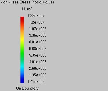
181 9. Select Residual Stress.


182 Residual Stresses are displayed in the assembly. The Von Mises Stress tool displays the deformations scale.
183

184 Displaying Tolerance Analysis Results This task will show you how to display tolerance analysis activities. The Analysis Data command displays assembly deformations or initial deformations of any assembly's component according to the selected activity. You can only report computed activities. See Computing Tolerance Analysis. Open the BasicTaaProcess2.CATProcess document. 1. Compute the Release.2 activity. For more information, see Computing a Tolerance Analysis. 2. Click the Analysis Data icon: The Analysis Results dialog box appears. Four analyses are available: Determinist Statistics Statistics All Direction Worst Case Three delta analyses are available: Absolute Product Delta Activity Delta Three results are available:

185 Annotations Forces Stiffness 3. Click on the Release.2 activity in the process list to display it.
186 Editing Tolerance Analysis Images This task will show you how to display tolerance analysis images. This command allows you to display analysis images for all assembly components associated with an activity. You can edit a tolerance analysis image of an activity only after you are performing a visualization of this activity, see Visualizing Tolerance Analysis Results. For more detail about the new Image Edition dialog box options, see Image Edition Dialog Box and Advanced Edition for Images and Local Sensors. Open the BasicTaaProcess2.CATProcess document. 1. Compute the Release.2 activity. See Computing Tolerance Analysis. 2. Click the Visualization icon: 3. Select the Release.2 activity and click OK in the Visualization dialog box. 4. Click the Edit Images icon: 5. Select the Release.2 activity. The Image Edition dialog box appears.
187 6. Select the desired options for display.
188 Saving Tolerance Analysis Documents This task will show you how to save tolerance analysis documents. 1. Click the File -> Save All As... command. The Save All As dialog box appears.
189 Exporting Data This task will show you how to export tolerance analysis data. The data structure of the exported file is the same as the tolerance analysis data structure. It will be possible to import the text file using Import Data command of the workbench, see Importing Tolerance Analysis Data and Tolerance Analysis Data. Note that only specifications that can be imported are exported in the text file (e.g. non Tolerance analysis data, as Analysis Geometric Variations, or Contact Links are not exported). The file header of the exported file is not customizable: Notice that the version of the exported file is a new version of the data file (51300). Constraints directions are dumped in the data file. <TaaData> Version: Mode: English ModelPath: Absolute LengthUnit: Millimeter ForceUnit: Newton... <EndTaaData> The data structure must contain: Only one root product. Only one root resource. TasPointPart and TasResources files are not exported (they are created when importing the data). If exported CATPart document contains Tolerance analysis annotations, you must delete these annotations in the text file generated. This functionality is standalone in this application. Open the BasicTaaProcess2.CATProcess document. 1. Click the Export Data icon: The Export dialog box appears. 2. Specify the folder and file name where to export the file and click Save.
190 Handling Inconsistent Model Set Up These tasks described you a list of inconsistency in the Tolerance Analysis of Deformable Assembly model set up, which can be raised during the computation. Rigid-Body Motion Singularity Restitution Over-Constrained Singularity Restitution Meshing Connection Error

191 Rigid-Body Motion Singularity Restitution This task will show you how to visualize a rigid-body motion singularity. This singularity is a global singularity type. If singularity error exists, it is raised during the computation only. If several singularity errors exist, they can be raised only one by one. This means that you must correct the singularity and re-run the computation to encounter the next singularity if exists. Open the RigidBodyMotion CATProcess document. 1. Click the Compute icon: The Compute dialog box appears. 2. Select the POSITIONING.1 activity in the process list. 3. Click OK. The Error dialog box appears during the computation.
192 4. Click OK. 5. Click the Visualization icon: The Visualization dialog box appears. 6. Select the POSITIONING.1 activity in the process list. The rigid-body motion singularity is visualized.

193 7. Click OK.
194 Over-Constrained Singularity Restitution This task will show you how to visualize an redundant constraint singularity (locally over-constrained) generated by mechanical joints, fastenings, contacts. This singularity is a local singularity type. If singularity error exists, it is raised during the computation only. If several singularity errors exist, they can be raised only one by one. This means that you must correct the singularity and re-run the computation to encounter the next singularity if exists. Open the OverConstrained CATProcess document. 1. Click the Compute icon: The Compute dialog box appears. 2. Select the POSITIONING.1 activity in the process list. 3. Click OK. The Error dialog box appears during the computation.
195 4. Click OK. 5. Click the Visualization icon: The Visualization dialog box appears. 6. Select the POSITIONING.1 activity in the process list. 7. Click OK.

196 8. Click the Edit Images icon: and select the POSITIONING.1 activity in the process list. The Image Edition dialog box appears. See Displaying Tolerance Analysis Images. 9. Select the SYMBOL type and uncheck the Display on deformed mesh option. The over-constrained singularity is visualized with red arrows.

197 10. Click OK.
198 Meshing Connection Error After a computation, you may encounter an error message raised by the meshing connection operation. This message indicates that the application was not able to generate some interpolation elements corresponding to some specifications (spec name / point name). This message occurs when the specification is invalid or when the Maximum distance between geometry and point value is too small for the specification. See Meshes option. When facing this problem, the Edit/Find functionality can be used to get a hand on the specification mentioned in the message. Reframe on and edition (through double-click) are then used to identify the problem.


199 Workbench Description The Tolerance Analysis of Deformable Assembly workbench looks like this (move the mouse over image's links and have the enlarged image and corresponding description pop up):

200 Tolerance Analysis of Deformable Assembly Menu Bar This section presents the main menu bar available when you run the application and before creating or opening a document: Start File Edit View Insert Tools Windows Help Insert For... New Analysis Import Mesh... Import Data... Supports Mechanical Joint... Positioning System... Fastening Elements Contacts Annotations Annotations Bag... Activities See... Creating a New Tolerance Analysis Importing Meshes Importing Tolerance Analysis Data Insert Supports Menu Creating a Mechanical Joint Creating a Positioning System Insert Fastening Elements Menu Insert Contacts Menu Insert Annotations Menu Creating Annotation Bags Insert Activities Menu Tools

201 For... New Analysis Import Mesh... Import Data... See... Creating a New Tolerance Analysis Importing Meshes Importing Tolerance Analysis Data
202 Insert Supports Menu This section presents the Insert Supports menu: Insert -> Supports For... Rigid Support Flexible Support See... Creating a Rigid Support Creating a Flexible Support

203 Insert Fastening Elements Menu This section presents the Insert Fastening Elements menu: Insert -> Fastening Elements For... Spot Welding... Riveting... Bolting... Spot Gluing... See... Creating Fastening Elements Creating Fastening Elements Creating Fastening Elements Creating Fastening Elements
204 Insert Contacts Menu This section presents the Insert Contacts menu: Insert -> Contacts For... Contacts... Contact Links... See... Creating a Contact Linking Contacts

205 Insert Annotations Menu This section presents the Insert Annotations menu: Insert -> Annotations For... Annotations... Correlated Annotations... Distance Between Two Points... Analysis Geometric Variations... See... Creating a Deviation Creating a Correlated Deviation Creating a Distance Between Two Points Creating Analysis Geometric Variations

206 Insert Activities Menu This section presents the Insert Activities menu: Insert -> Activities For... Positioning Activity Fastening Activity Release Activity Already Done Fastening Activity See... Adding an Activity Adding an Activity Adding an Activity Adding an Activity
207 Tools Computed Results Menu This section presents the Tools Computed Results menu: Tools -> Computed Results For... See... Visualization... Visualizing Tolerance Analysis Results Analysis Data... Edit Images... Displaying Tolerance Analysis Results Displaying Tolerance Analysis Images
208 Analysis Toolbar See Creating a New Tolerance Analysis See Importing Meshes See Importing Tolerance Analysis Data See Exporting Data
209 Elements Toolbar Jump to Supports Sub-Toolbar See Creating a Mechanical Joint See Creating a Positioning System Jump to Fastening Elements Sub-Toolbar Jump to Contacts Sub-Toolbar Jump to Annotations Sub-Toolbar See Creating Annotation Bags Supports Sub-Toolbar See Creating a Rigid Support See Creating a Flexible Support Fastening Elements Sub-Toolbar
210 See Creating Fastening Elements See Creating Fastening Elements See Creating Fastening Elements See Creating Fastening Elements Contacts Sub-Toolbar See Creating a Contact See Linking Contacts Annotations Sub-Toolbar See Creating a Deviation See Creating a Correlated Deviation See Creating a Distance Between Two Points See Creating Analysis Geometric Variations
211 Process Toolbar See Linking Activities See Managing Items See Managing Items See Linking Activities Jump to Activities Sub-Toolbar Activities Sub-Toolbar See Adding an Activity See Adding an Activity See Adding an Activity See Adding an Activity
212 Tools Toolbar See Reporting Tolerance Analysis Elements See Computing Tolerance Analysis Jump to Computed Results Sub-Toolbar Computed Results Sub-Toolbar See Visualizing Tolerance Analysis Results See Displaying Tolerance Analysis Results See Displaying Tolerance Analysis Images
213 Customizing Before you start your first working session, you can customize the way you work to suit your habits. This type of customization is stored in permanent setting files: these settings will not be lost if you end your session. 1. Select the Tools -> Options command. The Options dialog box opens. 2. Select the Analysis & Simulation category in the left-hand box. 3. Select the Tolerance Analysis of Deformable Assembly sub-category. Three tabs are displayed: The General tab lets you set the general options. The Fastening tab lets you define the fastening options. The Tolerancing tab lets you set the tolerancing options. 4. Select the Infrastructure category in the left-hand box. 5. Select the Product Infrastructure sub-category. One tab also interfere with Tolerance Analysis of Deformable Assembly. Cache Management 6. Select the Digital Process for Manufacturing category in the left-hand box. One tab also interfere with Tolerance Analysis of Deformable Assembly. Tree 7. Select the Analysis & Simulation category in the left-hand box. One tab also interfere with Tolerance Analysis of Deformable Assembly. External Storage


214 General This page deals with the options concerning: The File Out Folder. The Feature Colors. The Links Creation Mode. The Meshes. The Node and Point Filter. File Out Folder Defines the file out folder paths: External Result Path Defines the folder path where external results should be saved. By default, the value of the CATTemp variable. Computation Result Path Defines the folder path where computation results should be saved. By default, the value of the CATTemp variable. Temporary Result Path Defines the folder path where temporary results should be saved. By default, the value of the CATTemp variable. Feature Colors
215 Defines the tolerance analysis feature colors: Rigid Support Defines the default color of rigid supports. By default, the color is magenta. See the screen capture. Flexible Support Defines the default color of flexible supports. By default, the color is magenta. See the screen capture. Mechanical joint Defines the default color of mechanical joints. By default, the color is light blue. See the screen capture. Fastening Defines the default color of fastening. By default, the color is blue. See the screen capture. Contact Defines the default color of contacts. By default, the color is green. See the screen capture. Links Creation Mode Defines the contact link creation mode: Automatic Defines whether the links creation can be automatic. Using the automatic mode, the application takes into account the appropriate contacts around a fastening element. Otherwise, you must define the list of contacts taken into account by a given fastening element. By default, this option is selected. Meshes
216 Defines the meshes options: Maximum distance between geometry and point Defines the maximum distance allowed between a point you defined as a node and the part geometry. Beyond this distance, the point is not taken into account when the mesh is generated automatically. By default, the value is 5mm. Node and Point Filter Defines the node and point compatibility with tolerance analysis features: Activate Filter during selection: the application allows you to select nodes and points compatible with the tolerance analysis feature. Activate Filter during creation: the application allows you to select nodes and points compatible with the tolerance analysis feature. Deactivate Filter: the application checks the validity of the tolerance analysis features when operating the computation. By default, the Activate Filter during selection option is selected.
217 Fastening This page deals with the options concerning: The Spot Welding. The Riveting. The Bolting. The Spot Gluing. Spot Welding Defines the spot welding options: Joint type before welding Defines the mechanical joint taken into account to represent spot welding before a spot welding activity: Point Planar By default, the Point representation is selected. Joint type after welding Defines the mechanical joint taken into account to represent spot welding after a spot welding activity: Revolute Spherical: only when Point is selected in Joint type before welding. By default, the Revolute representation is selected. Riveting Defines the riveting options: Joint type before riveting Defines the mechanical joint taken into account to represent riveting before a riveting activity:
218 Point Planar Spherical Revolute By default, the Point representation is selected. Joint type after riveting Defines the mechanical joint taken into account to represent riveting after a riveting activity: Revolute. Spherical: only when Point or Spherical is selected in Joint type before riveting. By default, the Spherical representation is selected. Bolting Defines the bolting options: Joint type before bolting Defines the mechanical joint taken into account to represent bolting before a bolting activity: Point Planar Spherical Revolute By default, the Point representation is selected. Joint type after bolting Defines the mechanical joint taken into account to represent bolting after a bolting activity: Revolute. Spherical: only when Point or Spherical is selected in Joint type before bolting. By default, the Spherical representation is selected. Spot Gluing
219 Defines the spot gluing options: Joint type before gluing Defines the mechanical joint taken into account to represent spot gluing before a spot gluing activity: Point Planar By default, the Point representation is selected. Joint type after gluing Defines the mechanical joint taken into account to represent spot gluing after a spot gluing activity: Revolute Spherical: only when Point is selected in Joint type before gluing. By default, the Revolute representation is selected.
220 Tolerancing This page deals with the options concerning: The Conversion Range. The Tolerance Translation Reduction Coefficient. The Minimum Variance. Conversion Range Defines the conversion range options: Range Defines the range value to switch between tolerance interval and statistics law. For example, with a range value of 3 and applied to a normal law, 99.73% of measures contained in the tolerance interval represent the statistics law field. By default, the range is 3. Tolerance Translation Reduction Coefficient Defines the tolerance translation reduction coefficient options: Coefficient Value Defines the coefficient value to translate functional tolerances due to form uncertainty in deviation point grid. By default, the coefficient value is 1. Minimum Variance Defines the minimum variance options: Minimum Variance Defines the percentage value of minimum variance to translate functional tolerances. By default, the minimum variance is 50%.
221 Cache Management for Tolerancing Analysis of Deformable Assembly This page deals with the options concerning: The Cache Activation. Cache Activation Please refer to Infrastructure user's guide to know more about the Product Structure Cache Management options. Work with the cache system You must to unselect this option to work with Tolerancing Analysis of Deformable Assembly. By default, this option is not selected.

222 Displaying the Tolerancing Analysis of Deformable Assembly's Applicative Data This page deals with the options concerning: The Hierarchy tree. Hierarchy tree Please refer to Infrastructure user's guide to know more about the Digital Process for Manufacturing Tree options. Attributes You need to select this option to display the Tolerancing Analysis of Deformable Assembly's applicative data. By default, this option is not selected.
223 Disabling the Computation Data Clearing This page deals with the options concerning: The Computation Data Management on Save. Computation Data Management on Save Please refer to Infrastructure user's guide to know more about the Analysis & Simulation External Storage options. Automatic clearing of computation data You must to unselect this option to keep the resulting computation of a tolerance analysis when you save the CATProcess document. By default, this option is not selected.
224 Reference Information This section contains reference information about the Tolerance Analysis of Deformable Assembly workbench.
225 Transparent Tolerance Analysis This reference describes how the Tolerance Analysis of Deformable Assembly workbench interprets the specifications and results generated with other CATIA and DELMIA workbenches. Interpreting the Structural Behavior of Product Components Interpreting Annotation Tolerances Interpreting Datum Reference Frame

226 Interpreting the Structural Behavior of Product Components To compute a tolerance analysis, a structural analysis representation is required for each product component. When a structural analysis representation does not exist or it is not associated with the product component, a new structural analysis representation is automatically created and associated with the product component. The creation and association is automatic (and there is no option). This behavior is only available for CATPart documents. You may generate the structural analysis representations only by using the Only preprocessing option in the Compute dialog box. Modify them if necessary from the representation created containing the part document in the Generative Structural Analysis workbench. When a structural analysis representation exists, you can associate it to its corresponding component instance using the Manage representation contextual command. This command lets you add the representation from a CATAnalysis document. See the Product Structure documentation for more details.
227 Interpreting Annotation Tolerances When a tolerance analysis is computed, the annotations located on: components in the assembly are interpreted as input variations. assemblies are interpreted as output annotations. This behavior is only available for V5 annotations associated with a datum reference frame and thin parts. The interpreting operation is automatic. You can define the options using the Tools -> Options command. See Tolerancing page. Semantic annotations such as defined by the ISO ASME/ANSI standards, are taken into account only if applied to surfacic component.
228 Interpreting Datum Reference Frames Instead of using positioning systems, you can use Datum Reference Frame to define correlated deviations and distance point-point annotations. In this case Datum Reference Frames may be assigned as item in a process activity and interpreted as positioning system. Note that Datum Reference Frames do not allow to perform release nor tightening.
229 Tolerance Analysis Data Structure This reference will describe the tolerance analysis data structure. Data is contains in a text file. This file may contains the tolerance analysis assembly, tolerance analysis resources, the tolerance analysis elements, the assembly process. For more information, see Importing Tolerance Analysis Data. The data structure is made of: An introduction, File Header The assembly definition, Tolerance Analysis Assembly The resources definition, Tolerance Analysis Resources The elements definition, Tolerance Analysis Elements The assembly process, Assembly Process A conclusion, File Footer The four main parts may be combined as in the following examples: Tolerance Analysis Assembly only. Tolerance Analysis Assembly + Tolerance Analysis Resources Tolerance Analysis Assembly + Tolerance Analysis Resources+ Tolerance Analysis Elements Tolerance Analysis Assembly + Tolerance Analysis Resources+ Tolerance Analysis Elements + Assembly Process
230 File Header The file header data structure defines settings for data reading. This part of data structure is mandatory. Each part or subpart is included between a start tag <xxx> and a end tag <Endxxx>. These tags are mandatory. <TaaData> Version: 5700 Mode: English ModelPath: Absolute DefineDirections: No LengthUnit: Millimeter ForceUnit: Newton... <TaaData> Start tag of data structure. See File Footer. Version: xyzz Defines the application data structure version, where: x is the version number. y the release number. zz the service pack number. Mode: English or French Defines the decimal separator for real number in this file: A point "." for English. A coma "," for French. ModelPath: Absolute or Relative Defines the path taken into account to read a component, see Path: Absolute sets the component full path. Relative sets the component path from the data file folder. LengthUnit: Millimeter Defines the data length unit, Millimeter only. ForceUnit: Newton Defines the data force unit, Newton only.
231 Tolerance Analysis Assembly The tolerance analysis assembly data structure defines the assembly's structure. Assembly components are CATPart, CATAnalysis or model. This part of data structure is mandatory. Each part or subpart is included between a start tag <xxx> and a end tag <Endxxx>. These tags are mandatory.... <Products> Number: 2... <Products> Start tag of tolerance analysis assembly. Number: 2 Defines the number of components.... Name: CurvedPlate Parent: RootProduct Instance: No Path: E:\www\awsDocV5R6\TaaEnglish\taaug.doc\src\samples\CurvedPlate.model Symmetry: No Positioning: Name: ComponentName Defines the component name. Parent: ParentName Defines the parent component of the component. Instance: No Defines if the component is an instance of component or not, No only.
232 Path: PathName Defines the component path according to the ModelPath option. Symmetry: No Defines if the component is duplicate by symmetry or not, No only. Positioning: PositioningMatrix Defines the positioning matrix of the component, the three first columns contain the rotation components and the last column the translation components.... <EndProducts>... <EndProducts> End tag of tolerance analysis assembly.
233 Tolerance Analysis Resources The tolerance analysis resources data structure defines the resource's structure. This part of data structure is optional. Each part or subpart is included between a start tag <xxx> and an end tag <Endxxx>. These tags are mandatory.... <Resources> Number: 1... <Resources> Start tag of tolerance analysis resources. Number: 1 Defines the number of resources.... Name: TasResources Parent: RootResource Instance: No NoV4Model Symmetry: No Positioning: Name: ResourceName Defines the resource name. Parent: ParentName Defines the parent resource of the resource. Instance: No Defines if the resource is an instance of resource or not, No only. NoV4Model Defines the resource as no CATIA V4 model reference.
234 Symmetry: No Defines if the resource is duplicated by symmetry or not, No only. Positioning: PositioningMatrix Defines the positioning matrix of the resource.... <EndResources>... <EndResources> End tag of tolerance analysis resources.
235 Tolerance Analysis Elements The tolerance analysis elements data structure defines the element's structure. This part of data structure is optional. Each part or subpart is included between a start tag <xxx> and an end tag <Endxxx>. These tags are mandatory. The elements are: Supports Joints Positioning Systems Fastenings Contacts Annotations Annotation Bags Supports... <Supports> Number: <Supports> Start tag of tolerance analysis support elements. Number: 12 Defines the number of supports.
236 ... Name: Support.1 Resource: TasResources NumberOfPoints: 1 Stiffness: Rigid PointName: SUP1 Coordinates: Name: Support.2 Resource: TasResources NumberOfPoints: 2 Stiffness: Flexible PointName: SUP2 Coordinates: PointName: SUP3 Coordinates: StiffnessesKind: Element Stiffnesses: Zdirection: Name: SupportName Defines the support name. Resource: ResourceName Retrieves the resource associated with the support from its name. NumberOfPoints: 1 Defines the number of points defining the support. Stiffness: Rigid or Flexible Defines the support stiffness. PointName: SUP1 Defines the point name where to create the support. Coordinates: Defines the point coordinates where to create the support. [StiffnessesKind: Element or Rectangular or Circular ] optional Defines the beam section between two points of the support. [Stiffnesses: ] optional Defines the beam stiffness between two points of the support. Use only with Flexible option in Stiffness and Element option in StiffnessesKind.
237 [Young Module:.216e6] optional Defines the beam section Young module. Use only with Flexible option in Stiffness and Circular or Rectangular option in StiffnessesKind. [Poisson Coefficient: 0.3] optional Defines the beam section Poisson coefficient. Use only with Flexible option in Stiffness and Circular or Rectangular option in StiffnessesKind. [Base, Height: ] optional Defines the beam rectangular section base and height. Use only with Flexible option in Stiffness and Rectangular option in StiffnessesKind. [Radius: ] optional Defines the beam circular section radius. Use only with Flexible option in Stiffness and Circular option in StiffnessesKind. [Zdirection: or NoZdirection] optional Defines the Z direction for the beam profile between two points of the support if this profile is not circular, no Z direction is needed when the profile is circular. Use only with Flexible option in Stiffness and Element or Rectangular option in StiffnessesKind.... <EndSupports>... <EndSupports> End tag of tolerance analysis support elements. Joints... <Joints> Number: <Joints> Start tag of tolerance analysis joint elements.
238 Number: 12 Defines the number of joints.... Name: Joint.1 Type: Spherical Between: CurvedPlate TasResources PointName: ST1 Coordinates: Xdirection: Zdirection: Name: JointName Defines the joint name. Type: TypeName Defines the joint type name: Point for point joint. AnnularLinear for annular-linear joint. EdgeSlider for edge Slider joint. Planar for planar joint. Spherical for spherical joint. SphericalWithPin for spherical with pin joint. Cylindrical for cylindrical joint. Screw for screw joint. Revolute for revolute joint. Prismatic for prismatic joint. Rigid for rigid joint. Between: ReferenceName1 ReferenceName2 Retrieves the two references associated with the joint from their names. The references must be two components or a component and a resource or a component and a support. [PointName: ST1] optional Defines the point name where to create the joint. Do not use when a support is used as reference. [Coordinates: ] optional
239 Defines the point coordinates where to create the joint. Do not use when a support is used as reference. Xdirection: Defines the X direction for the joint. [Zdirection: ] optional Defines the Z direction for the joint. Use only with joint type different from Point option in Type.... <EndJoints>... <EndJoints> End tag of tolerance analysis joint elements. Positioning Systems... <PositioningSystems> Number: 4... <PositioningSystems> Start tag of tolerance analysis positioning system elements. Number: 4 Defines the number of positioning systems.
240 ... Name: PositionSys1 NumberOfJoints: 6 JointName: Joint.1 Tightening: 0 JointName: Joint.2 Tightening: 0 JointName: Joint.3 Tightening: 0 JointName: Joint.4 Tightening: 0 JointName: Joint.5 Tightening: 0 JointName: Joint.6 Tightening: 0... Name: PositioningSystemName Defines the positioning system name. NumberOfJoints: 6 Defines the number of joints defining the positioning system. JointName: JointName Retrieves the joint associated with the positioning system from its name. Tightening: 0 either Release: 2 For example, according to the table below to tighten or release the three rotations Rx, Ry and Rz, add up the value associated with them: = 56 to define the tightening or release value. Note: Tightening: 0 means no tightened neither released translation or rotation, and Release: 0 does not exist. Tx Ty Tz Rx Ry Rz <EndPositioningSystems>... <EndPositioningSystems> End tag of tolerance analysis positioning system elements.
241 Fastenings... <Fastenings> Number: 4 DefineDirections: Yes... <Fastenings> Start tag of tolerance analysis fastening elements. Number: 4 Defines the number of fastenings. DefineDirections: Yes or No Allows the deviation directions to be different from node normal directions: Yes to define new directions. No to use node normal directions.... Name: SpotWelding.1 Type: SpotWelding Diameter: Between: CurvedPlate Plate PointName: SW1 Coordinates: Name: FasteningName Defines the fastening name. Type: FasteningType Defines the fastening type:
242 SpotWelding for spot welding. Riveting for riveting. Bolting for bolting. SpotGluing for spot gluing. Diameter: Defines the fastening diameter. Between: ReferenceName1 ReferenceName2 Retrieves the two references associated with the fastening from their names. The references must be two components. PointName: PointName Defines the point name of the fastening. Coordinates: Defines the point coordinates of the fastening. [Direction: ] optional Defines the fastening direction. Use only with Yes option in DefineDirections.... <EndFastenings>... <EndFastenings> End tag of tolerance analysis fastening elements. Contacts... <Contacts> Number: 1 DefineDirections: Yes... <Contacts>
243 Start tag of tolerance analysis contact elements. Number: 2 Defines the number of contacts. DefineDirections: Yes or No Allows the deviation directions to be different from node normal directions: Yes to define new directions. No to use node normal directions.... Name: Contact.1 NumberOfPoints: 8 Between: CurvedPlate Plate PointName: Cont61 Coordinates: PointName: Cont63 Coordinates: PointName: Cont65 Coordinates: PointName: Cont68 Coordinates: PointName: Cont70 Coordinates: PointName: Cont72 Coordinates: PointName: Cont75 Coordinates: PointName: Cont76 Coordinates: Name: ContactName Defines the contact name. NumberOfPoints: 8 Defines the number of contact points. Between: ReferenceName1 ReferenceName2 Retrieves the two references associated with the contact from their name. The references must be two components. PointName: PointName
244 Defines a point name of the contact. Coordinates: Defines a point coordinates of the contact. [Direction: ] optional Defines the contact direction. Use only with Yes option in DefineDirections.... <EndContacts>... <EndContacts> End tag of tolerance analysis contact elements. Annotations... <Annotations> Number: 3 DefineDirections: No... <Annotations> Defines the number of annotation sets. Number: 3 Defines the number of annotation sets. DefineDirections: Yes or No Allows the deviation directions to be different from node normal directions: Yes to define new directions. No to use node normal directions.
245 ... Name: TPSSet1 ProductName: CurvedPlate NumberOfToleranceTypes: 1 ToleranceType: Deviation NumberOfTolerances: 7 PositioningSystem: PositionSys3 Law: Normal ToleranceName: Dev.1 PointName: *PT4 Coordinates: ToleranceName: Dev.2 PointName: *PT5 Coordinates: ToleranceName: Dev.3 PointName: *PT6 Coordinates: ToleranceName: Dev.4 PointName: *PT7 Coordinates: ToleranceName: Dev.5 PointName: *PT8 Coordinates: ToleranceName: Dev.6 PointName: *PT9 Coordinates: ToleranceName: Dev.7 PointName: *PT80 Coordinates: Name: AnnotationName Defines the annotation set name. ProductName: ComponentName Retrieves the component associated with the annotation set from its name. NumberOfToleranceTypes: 1 Defines the number of tolerance type used, deviation and/or correlated deviation only and/or distance between two points. ToleranceType: Deviation or CorrelatedDeviation or DistancePtPt Defines the tolerance type:
246 Deviation for deviation. CorrelatedDeviationfor correlated deviation. DistancePtPt for distance between two points. NumberOfTolerances: 7 Defines the number of tolerance of the tolerance type. PositioningSystem: PositioningSystemName Retrieves the positioning system associated with the annotation type from its name. Law: Normal or Uniform or Constant or Poisson or Pearson or Snedecor or Sample Defines the statistic law associated with the tolerance type. Use only Normal, Uniform, Constant, Poisson, Pearson and Snedecor laws with Deviation or DistancePtPt option in ToleranceType. Use only Sample law with CorrelatedDeviation option in ToleranceType [SampleFile: No or PathFileName] optional Defines the absolute path and filename containing the correlated deviation law or not. Use only with CorrelatedDeviation option in ToleranceType. [Mean: 1.] optional Defines the means in Normal law. Use only with Normal option in Law. [Standard Deviation: 0.1] optional Defines the standard deviation in Normal law. Use only with Normal option in Law. [MinValue: -1.] optional Defines the minimal value in Uniform law. Use only with Uniform option in Law. [MaxValue: 1.] optional Defines the maximal value in Uniform law. Use only with Uniform option in Law. [Constant: 1.] optional Defines the constant value in Constant law. Use only with Constant option in Law. [Lambda: 5] optional Defines the lambda value in Poisson law. Use only with Poisson option in Law. [Nu: 1.] optional Defines the nu value in Pearson law. Use only with Pearson option in Law.
247 [DOF_m: 4] optional Defines the dof m value in Snedecor law. Use only with Snedecor option in Law. [DOF_n: 5] optional Defines the dof n value in Snedecor law. Use only with Snedecor option in Law. ToleranceName: ToleranceName Defines a tolerance name of the tolerance type. PointName: PointName Defines a point name of the tolerance type. Coordinates: Defines a point coordinates of the tolerance type. [Direction: ] optional Defines the annotation direction. Use only with Yes option in DefineDirections.... <EndAnnotations>... <EndAnnotations> End tag of tolerance analysis annotation set elements. Annotation Bags... <AnnotationBags> Number: 2... <AnnotationBags> Start tag of tolerance analysis annotation bags. Number: 2
248 Defines the number of annotation bags.... Name: TPSBag1 SetName: TPSSet3 NumberOfTolerances: 14 Dev.1 Dev.2 Dev.3 Dev.4 Dev.5 Dev.6 Dev.7 Dev.8 Dev.9 Dev.10 Dev.11 Dev.12 Dev.13 Dev.14 Name: TPSBag2 SetName: TPSSet3 NumberOfTolerances: All... Name: AnnotationBagName Defines the annotation bag name. SetName: AnnotationName Retrieves the annotation set associated with the annotation bag from its name. NumberOfTolerances: 14 or All Defines the number of tolerance of the annotation set: A number to define a subset of annotations contain in the annotation set. All to retrieve all annotations contain in the annotation set. [ToleranceName1 ToleranceName2 ToleranceName3... ] optional Retrieves the tolerances associated with the annotation bag from their names. Use only with a numerical value option in NumberOfTolerance.... <EndAnnotationBags>... <EndAnnotationBags> End tag of tolerance analysis annotation bag elements.
249 Assembly Process The assembly process data structure defines the process's structure. This part of data structure is optional. Each part or subpart is included between a start tag <xxx> and an end tag <Endxxx>. These tags are mandatory. Assembly Process... <AssemblyProcess> Number: 5... <AssemblyProcess> Start tag of assembly process. Number: 5 Defines the number of assembly activities.... Name: Activity.1 Activity: POSITIONING PreviousActivities: No PositioningSystems: PositionSys1 PositionSys2 Fastenings: No TolerancingBag: TPSBag1... Name: ActivityName Defines the activity name. Activity: ActivityType Defines the activity type: POSTIONING for positioning activity. FASTENING for fastening activity. RELEASE for release activity.
250 PreviousActivities: Activity1 Activity2... or No Retrieves the previous activities before this one from their name: A list of activity names. No when there is no previous activity. PositioningSystems: PositioningSystemName1 PositioningSystemName2... Retrieves the positioning system names associated with the activity. Fastenings: FasteningName1 FasteningName2 or No Retrieves the fastening names associated with the activity from their name: A list of fastening names when the activity type is FASTENING. See Activity. No when the activity type is not FASTENING. See Activity. TolerancingBag Retrieves the tolerancing bag associated with the activity from its name.... <EndAssemblyProcess>... <EndAssemblyProcess> End tag of assembly process.
251 File Footer The file footer data structure defines the end of data reading. This part of data structure is mandatory. Each part or subpart is included between a start tag <xxx> and an end tag <Endxxx>. These tags are mandatory.... <EndTaaData> <EndTaaData> End tag of data structure. See File Header.
252 Measurement Data Measurement file data structure are contain in a text file. This file contains the measure specifications for an analysis geometric variations annotation. <TaaData> Version: 5700 Mode: English LengthUnit: Millimeter... <TaaData> Start tag of data structure. Version: xyzz Defines the application data structure version, where: x is the version number. y the release number. zz the service pack number. Mode: English or French Defines the decimal separator for real number in this file: A point "." for English. A coma ","for French. LengthUnit: Millimeter Defines the data length unit, Millimeter only.... <Measures> NumberOfVariables: 7 NumberOfMeasures: <Measures> Start tag of measures.
253 NumberOfVariables: 7 Defines the number of variables. NumberOfMeasures: 10 Defines the number of measures Matrix where rows represent measures and columns represent variables.... <EndPMeasures>... <EndMeasures> End tag of measures.... <EndTaaData> <EndTaaData> End tag of data structure.
254 Statistic Laws Statistic laws are used to characterize deviation annotations. interpret annotation tolerance in a deviation annotation. These deviation annotations can be directly specified by the user or generated from a annotation's tolerance translation. For a statistical analysis, an annotation tolerance is interpreted as random variable or variate. For a determinist analysis, the mean of the annotation tolerance is used as determinist value. Normal Law: describe the Normal probability law equations. Uniform Law: describe the Uniform probability law equations. Constant Law: describe the Constant probability law equations. Pearson Law: describe the Pearson probability law equations. Poisson Law: describe the Poisson probability law equations. Snedecor Law: describe the Snedecor probability law equations.
255 Normal Law The Normal law is parameterized by a mean (unit: millimeter) and a standard deviation (unit: millimeter). Another name for the Normal law is Gaussian law. Let's take a random variable following the Normal law, then: is distributed according to the following density of probability: With mean: With variance: With standard deviation:
256 Uniform Law The Uniform law is parameterized by a lower limit (unit: millimeter) and a upper limit (unit: millimeter). Another name for the Uniform law is Rectangular law. Let's take a random variable following the Uniform law, then: is distributed according to the following density of probability, where: With mean: With variance: With standard deviation:
257 Constant Law The Constant law is parameterized by a constant (unit: millimeter). Let's take a random variable following the Constant law, then: is always equals to the constant: With mean: With variance: With standard deviation:
258 Pearson Law The Pearson law is parameterized by (no unit). Another name for the Pearson law is Chi-squared law. If random variables follows the Normal law with mean 0 and variance 1, then: Let's take a random variable following the Pearson law, then: is distributed according to the following density of probability, where: And where is a Gamma function. With mean: With variance: With standard deviation:
259 Poisson Law The Poisson law is parameterized by (unit: millimeter). Let's take a random variable following the Poisson law, then: is distributed according to the following density of probability, where: With mean: With variance: With standard deviation:
260 Snedecor Law The Snedecor law is parameterized by two non-dimensional numbers and. Let's take a random variable following the Snedecor law of parameters and, then can be expressed in terms of two random variables, following Pearson law respectively of parameter, as: is distributed according to the following density of probability, where: With mean: With variance: With standard deviation:
261 Interface Description This reference details Tolerance Analysis of Deformable Assembly interface. Image Edition Dialog Box Advanced Edition for Images and Local Sensors
262 Image Edition This task describes the Image Edition dialog box. The names of the images depend on: 1. physical type (for example: Displacement) 2. visualization type (for example: Symbol or Text) 3. criterion (for example: Norm or Vector component) You will find in the following table the available tabs and buttons in the Image Edition dialog box. Mono-occurrence solutions Multi-occurrence solutions Deformed Mesh image Mesh Visualization image Mesh Selections Preview Mesh Selections Occurrences Preview Other images Visu Selections More Preview Visu Selections Occurrences More Preview Mesh Tab
 with restraint excitation, you can specify if you want to visualize the image in an absolute axis (Absolute option) or in a")
263 On deformed mesh: lets you visualize results in deformed mode. In the case of Dynamic Response Analysis Case (Harmonic or Transient) with restraint excitation, you can specify if you want to visualize the image in an absolute axis (Absolute option) or in a relative axis (Relative option). Absolute: lets you visualize both the displacement and the elastic deformation of the part. Relative: lets you visualize only the elastic deformation of the part. Display free nodes: lets you display free nodes (nodes that are referenced by any element). Display nodes of elements: lets you visualize nodes of elements. Display small elements: lets you choose to display or not the very small elements. Shrink Coefficient: lets you shrink the element visualization. Visu Tab
 with restraint excitation, you can specify if you want to visualize the image in an absolute axis (Absolute option) or in a")
264 On deformed mesh: lets you visualize the deformation. In the case of Dynamic Response Analysis Case (Harmonic or Transient) with restraint excitation, you can specify if you want to visualize the image in an absolute axis (Absolute option) or in a relative axis (Relative option). Absolute: lets you visualize both the displacement and the elastic deformation of the part. Relative: lets you visualize only the elastic deformation of the part. Type: provides a list with visualization types (how). The list of visualization types depends on the selected image. Average iso: lets you visualize isolines at nodes. This visualization type uses the Material Rendering capabilities. Discontinuous iso: lets you visualize isolines at nodes of element. This visualization type uses the Material Rendering capabilities. Fringe: lets you color an element, a face of element or an edge of element according to the scalar value defined for this entity.

265 Text: lets you visualize results using text. Symbol: lets you visualize results using symbol. The available symbols depend on the values to be displayed. Criteria: provides a list of visualization criteria. The list of visualization criteria depends on the physical type of the selected image and the selected Type. Options...: lets you define visualization options. Only available if you installed the ELFINI Structural Analysis product. The dialog box that appears depends on the Type option you previously selected. For more details about this button, please click here. Options... button Here you will find the available visualization options you obtain using the Options... button: if you selected the Discontinuous iso, Average iso or Fringe type, the Visualization Options dialog box appears as shown bellow: Shrink Coefficient: lets you shrink the element visualization Display elements without value: lets you display elements with or without value Display small elements: lets you choose to display or not the very small elements This option is only available if you selected the Fringe type. if you selected the Symbol type, the Visualization Options dialog box appears as shown bellow:


266 Type: Representation: lets you choose between the symbol representation types. The number of the available representations depends on the visualization Type and Criteria. Color: Imposed: enables the color to be fixed. If this option is selected, you can use the Color Chooser. Size: Minimum length: lets you define the minimum symbol length. Maximum length: lets you define the maximum symbol length. Variable: enables the variability of the symbols in function of the value. Zoom sensitive: enables the length of the symbols to be zoom sensitive. if you selected the Text type, the Visualization Options dialog box appears as shown bellow: Color: Imposed: enables the color to be fixed. If this option is selected, you can use the Color Chooser.
 pre-processing specifications (under the Restraints, Loads and Masses sets in the specification")
267 Selections Tab The Selections tab lets you limit the image visualization to a list of entities. Available Groups: gives you the list of the available entities. The available entities could be: mesh parts (under the Nodes & Elements set in the specification tree) pre-processing specifications (under the Restraints, Loads and Masses sets in the specification tree) user groups (under the Groups set in the specification tree) You can filter the list of the available entities using the Filter groups... contextual menu. For more details, please click here. button: lets you activate the visualization of all the available entities contained in the Available Groups frame. button: lets you activate the visualization of entities selected in the Available Groups frame. button: lets you deactivate the visualization of entities selected in the Activated Groups
268 frame. button: lets you lets you deactivate the visualization of all the selected entities contained in the Activated Groups frame. Activated Groups: shows you the list of the entities you have activated the visualization. Multi-selection is available. In this case, the resultant selection is the union of the selected entities. You can double-click an entity to activate or deactivate the entity visualization. You can select entities directly in the specification tree or in the viewer. Minimum value and the maximum value of the color palette depend on the selected entities. If the Activated Groups field is empty, all the entities listed in the Available Groups field will be visualized. In case of pre-processing specifications, the type of entities contained in a selection may be different from a specification to another. For example: a Clamp symbolizes a list of nodes a Lineic Force symbolizes a list of edges a Pressure symbolizes a list of faces Filtering Groups a. Right-click in the Available Groups frame and select the Filter Groups... contextual menu as shown bellow: The Filter Groups dialog box appears.

269 User groups: lets you activate all the groups under the Groups set in the specification tree. 1D mesh parts: lets you activate all the 1D mesh parts under the Nodes and Elements set in the specification tree. 2D mesh parts: lets you activate all the 2D mesh parts under the Nodes and Elements set in the specification tree. 3D mesh parts: lets you activate all the 3D mesh parts under the Nodes and Elements set in the specification tree. Connection mesh parts: lets you activate all the connection mesh parts under the Nodes and Elements set in the specification tree. Specification groups: lets you activate all the entity under the Restraints, Loads and Masses sets in the specification tree. b. Set the desired options. c. Click OK in the Filter Groups dialog box. For example, with the following analysis specification tree:
270 if you activate the User groups and the Specification groups options, the Available Groups frame is updated as shown bellow: if you activate the 3D mesh parts and the Specification groups options, the Available Groups frame is updated as shown bellow:
 for a Frequency Case and a Harmonic Dynamic Response Case Buckling")
271 Occurrences Tab The Occurrences tab is available in the Image Edition dialog box only for multi-occurrence solutions. This tab gives you the list of modes with the associated: frequencies (Hz) for a Frequency Case and a Harmonic Dynamic Response Case Buckling factor for a Buckling Case


272 Time (s) for a Transient Dynamic Response Case

273 You can then activate separately each mode of the multi-occurrence solution. More and Less Buttons For more details on Values and Filters options, please click here. Preview button
274 By default, the visualization process is launched after each modification in the Image Edition dialog box. The Preview button allows you to launch the visualization process after performing all the needed changes in the Image Edition dialog box. The Preview button is available only if you deactivate the Automatic preview mode option in the Options dialog box (Tools -> Options... menu). For more details, please refer to the Customizing - Post Processing section of the Generative Structural Analysis User's Guide.
 or for the local sensors.")
275 Advanced Edition for Images and Local Sensors This task describes the advanced edition of the values that are taken into account for the visualization (advanced edition of images) or for the local sensors. Values: Position Value type Complex part Do not combine Filters: Show filters for Axis system Display locally Component Layer Lamina Ply id

276 Values Position: the position depends on the selected Type and Criteria option in the Visu tab. Node Linked to the mesh nodes. For each node, there is only one value. Node of element For each node, there is as many values as elements linked to this node. Center of element For each element center, there is only one value. Edge of element For each edge element, there is only one value. Face of element For each face element, there is only one value. Element For each element, there is only one value. Gauss point of element The position of the Gauss points depend on the type of element. For more details, please refer to the Finite Element Reference Manual. "(from solver)" indicates that the position is provided by the solver. To know more about the authorized position according to a selected Visu Type, please refer to the Frequently Asked Section - Post-Processing and Visualization section of the Generative

277 Structural Analysis User's Guide. Value type: corresponds to the type of the value (integer, real, double precision, complex, complex with double precision). Complex part: the complex part is available when the selected Value Type is complex and complex with double precision. Do not combine: if this option is not activated, combined values will be displayed whenever available. The desired resulting force will be displayed. if this option is activated, each specification (force, restraints and so forth) can be displayed separately. You will use the Value set list box to choose the desired value set. For example, if three forces were applied on a single surface, three values will be available in the Value set combo box. You can then select the desired Value set. Filters Show filters for: lets you select the entity type on which you will change the Axis System, Component, Layer, Lamina and Ply id options. The Show filters for option does not modify the feature you are editing. The following options are available: Nodes of 1D elements, Nodes of 2D elements or Nodes of 3D elements for a Node position type. 1D elements, 2D elements or 3D elements for an Element position type. Axis System: lets you select the current axis system to be used. For this, click the... button.

.")
278 The Axis system functionality is only available if you installed the ELFINI Structural Analysis (EST) product. The... button is only available if you have selected Vector, Tensor, Vector component or Tensor component as Criteria option. Global: lets you select the main axis system. User: lets you select an axis system feature (created in the Part Design workbench or the Generative Shape Design workbench). Manual: lets you specify an axis system by defining the origin coordinates and the different directions.
.")

279 Local: lets you select an axis system that is locally defined (related to a finite element). Display locally: lets you visualize the axis on each entity. The Display locally functionality is only available if you installed the ELFINI Structural Analysis (EST) product. in the image edition context.


280 Display locally option deactivated with a Global axis system Display locally option activated with a Global axis system Component: lets you select the component to visualize.
Electrical 3D Design & Documentation
 Electrical 3D Design & Documentation Page 1 Overview Conventions User Tasks Using Electrical 3D Design & Documentation Entering the Electrical Assembly Design Workbench Entering the Electrical Part Design
DMU Engineering Analysis Review
 DMU Engineering Analysis Review Overview Conventions What's New? Getting Started Entering DMU Engineering Analysis Review Workbench Generating an Image Visualizing Extrema Generating a Basic Analysis Report
DMU Engineering Analysis Review
 Page 1 DMU Engineering Analysis Review Preface Using This Guide Where to Find More Information Conventions What's New? Getting Started Inserting a CATAnalysis Document Using DMU Space Analysis From CATAnalysis
Electrical Harness Installation
 Electrical Harness Installation Page 1 Overview Conventions What's New? Getting Started Entering the Workbench Setting Up the Options Creating a Bundle Segment Document Creating Construction Points Defining
Fastening Review Overview Basic Tasks DMU Fastening Review Interoperability Workbench Description Customizing Index
 Fastening Review Overview Conventions Basic Tasks Displaying Joined Parts in a Balloon Running the Fastening Rules Analysis Reporting Creating Structural Reports Creating Flat Reports DMU Fastening Review
Electrical Harness Flattening
 Electrical Harness Flattening Overview Conventions What's New? Getting Started Accessing the Electrical Harness Flattening Workbench Defining the Harness Flattening Parameters Extracting Data Flattening
Electrical Library Version 5 Release 13. Electrical Library
 Electrical Library Page 1 Overview Conventions What's New? Getting Started Entering the Electrical Part Design Workbench Defining a Single Insert Connector Defining a Cavity Connection Point Entering Electrical
NC Manufacturing Verification
 NC Manufacturing Verification Overview Conventions What's New? User Tasks Accessing NC Manufacturing Verification Comparing the Machined Stock Part and the Design Part Pick Point Analysis in Video Mode
Equipment Support Structures
 Equipment Support Structures Overview Conventions What's New? Getting Started Setting Up Your Session Creating a Simple Structural Frame Creating Non-uniform Columns Creating Plates with Openings Bracing
Electrical Wire Routing
 Electrical Wire Routing Page 1 Overview Conventions What's New? Getting Started Accessing the Workbench Creating the Bundle Selecting Systems with External Data Routing Wires from External Data User Tasks
DMU Space Engineering Assistant User Guide
 Page 1 DMU Space Engineering Assistant User Guide Overview Conventions What's New? Getting Started User Tasks Setting Up Your Session Running a Interference Workbench Description DMU Space Engineering
DMU Space Engineering Assistant User Guide
 DMU Space Engineering Assistant User Guide Overview Conventions What's New? Getting Started User Tasks Setting Up Your Session Running an Interference Analysis Workbench Description DMU Space Engineering
NC Manufacturing Verification
 NC Manufacturing Verification Page 1 Preface Using This Guide Where to Find More Information Conventions What's New? User Tasks Accessing NC Manufacturing Verification Comparing the Machined Stock Part
Prismatic Machining Overview What's New Getting Started User Tasks
 Prismatic Machining Overview Conventions What's New Getting Started Enter the Workbench Create a Pocketing Operation Replay the Toolpath Create a Profile Contouring Operation Create a Drilling Operation
Equipment Support Structures
 Page 1 Equipment Support Structures Preface Using This Guide Where to Find More Information Conventions What's New? Getting Started Setting Up Your Session Creating a Simple Structural Frame Creating Non-uniform
Product Structure Version 5 Release 13. Product Structure
 Product Structure Page 1 Site Map Preface Conventions What's New? Basic Tasks Entering the Product Structure Workbench Opening a CATProduct with a Progress Bar Selecting Products only Selecting Modes Inserting
Circuit Board Design Version 5 Release 13. Circuit Board Design
 Circuit Board Design Page 1 Overview Conventions What's New? Getting Started Accessing the Circuit Board Workbench Creating a Board Pocket and Holes Constraint Area Exporting Data Importing Data User Tasks
Advanced Meshing Tools
 Page 1 Advanced Meshing Tools Preface Using This Guide More Information Conventions What's New? Getting Started Entering the Advanced Meshing Tools Workbench Defining the Surface Mesh Parameters Setting
Generative Part Structural Analysis Fundamentals
 CATIA V5 Training Foils Generative Part Structural Analysis Fundamentals Version 5 Release 19 September 2008 EDU_CAT_EN_GPF_FI_V5R19 About this course Objectives of the course Upon completion of this course
Human Posture Analysis
 Human Posture Analysis Overview Conventions What's New? Getting Started Creating a Manikin User Tasks Using the Posture Editor Selecting or Editing the DOF (Degree of Freedom) Displaying and Editing Angular
Electrical System Functional Definition
 Electrical System Functional Definition Overview Conventions What's New? Getting Started Creating a New System Creating Equipment Creating Connectors Creating a Signal Connecting Saving Your System User
Structure Preliminary Layout
 Structure Preliminary Layout Overview Conventions What's New? Getting Started Setting Up Your Session Defining the Hull Form Setting Up Your Grid Creating Molded Forms Creating a Compartment Creating Boundaries
Electrical System Functional Definition
 Electrical System Functional Definition Preface What's New? Getting Started Basic Tasks Advanced Tasks Workbench Description Customizing Glossary Index Dassault Systèmes 1994-2000. All rights reserved.
DMU Fitting Simulator
 Page 1 DMU Fitting Simulator Preface Using This Guide More Information Conventions What's New? Getting Started Using Tracks Starting a Session Recording a Track Using Automatic Path Finder Using the Smooth
Getting Started. These tasks should take about 20 minutes to complete. Getting Started
 Getting Started Getting Started This tutorial will guide you step-by-step through your first ELFINI and Generative Part Structural Analysis session, allowing you to get acquainted with the product. You
Preface. Version 5 Release 5. Mold Tooling Design
 Version 5 Release 5 Mold Tooling Design Preface Getting Started Basic Tasks Advanced Tasks Customization Workbench Description Glossary Index Preface The CATIA Version 5 Mold Tooling Design application
Knowledge Advisor Overview What's New? Getting Started User Tasks
 Knowledge Advisor Overview Conventions What's New? Getting Started Using Parameters Using Formulas Using Rules Using Checks User Tasks Working with Parameters Creating a Parameter Introducing Parameters
FEA BENDING, TORSION, TENSION, and SHEAR TUTORIAL in CATIA
 1 FEA BENDING, TORSION, TENSION, and SHEAR TUTORIAL in CATIA This tutorial shows the basics of a solid bending, torsional, tension, and shear FEA (Finite Elemental Analysis) model in CATIA. Torsion - page
Lesson 6: Assembly Structural Analysis
 Lesson 6: Assembly Structural Analysis In this lesson you will learn different approaches to analyze the assembly using assembly analysis connection properties between assembly components. In addition
Knowledge Expert Overview What's New? Getting Started Basic Tasks Advanced Tasks Reference
 Knowledge Expert Overview Conventions What's New? Getting Started Creating an Expert Check Creating an Expert Rule Basic Tasks About RuleBases Storing a Rule Base in a Catalog Using a Rule Base Stored
DMU Space Analysis Version 5 Release 13. DMU Space Analysis
 Page 1 DMU Space Analysis Preface Using This Guide More Information Conventions What's New? Getting Started Setting Up Your Session Measuring Minimum Distances Sectioning Detecting Clashes Measuring Between
Human Posture Analysis
 Human Posture Analysis Page 1 Preface Using This Guide Where to Find More Information Conventions What's New? Getting Started Creating a Manikin User Tasks Using the Posture Editor Segments Degree of Freedom
Structure Preliminary Layout
 Page 1 Structure Preliminary Layout Preface Using This Guide Where to Find More Information What's New? Getting Started Setting Up Your Session Defining the Hull Form Setting Up Your Grid Creating Molded
2: Static analysis of a plate
 2: Static analysis of a plate Topics covered Project description Using SolidWorks Simulation interface Linear static analysis with solid elements Finding reaction forces Controlling discretization errors
FreeStyle Shaper & Optimizer
 FreeStyle Shaper & Optimizer Preface What's New Getting Started Basic Tasks Advanced Tasks Workbench Description Customizing Glossary Index Dassault Systèmes 1994-99. All rights reserved. Preface CATIA
FreeStyle Shaper Optimizer & Profiler
 FreeStyle Shaper Optimizer & Profiler Page 1 Preface Using This Guide More Information What's New? Getting Started Starting the FreeStyle Workbench Creating a First Surface Editing the Surface Creating
DMU Optimizer Overview What's New? Getting Started User Tasks
 DMU Optimizer Overview Conventions What's New? Getting Started Starting a Session Generating a Silhouette Generating a Wrapping Generating a Thickness Generating an Offset Generating a Free Space User
Aerospace Sheetmetal Design
 Aerospace Sheetmetal Design Page 1 Overview Conventions What's New? Getting Started Entering the Aerospace SheetMetal Design Workbench Defining the Aerospace SheetMetal Parameters Creating a Web from a
Mechanical Design V5R19 Update
 CATIA V5 Training Foils Mechanical Design V5R19 Update Version 5 Release 19 August 2008 EDU_CAT_EN_MD2_UF_V5R19 1 About this course Objectives of the course Upon completion of this course you will be able
Elfini Solver Verification
 Page 1 Elfini Solver Verification Preface Using this Guide Where to Find More Information Conventions What's new User Tasks Static Analysis Cylindrical Roof Under its Own Weight Morley's Problem Twisted
Torsional-lateral buckling large displacement analysis with a simple beam using Abaqus 6.10
 Torsional-lateral buckling large displacement analysis with a simple beam using Abaqus 6.10 This document contains an Abaqus tutorial for performing a buckling analysis using the finite element program
MULTICAx STEP Plug-in
 MULTICAx STEP Plug-in Overview What's New User Tasks Requirements Methodologies and Advice Initializing the Environment Importing STEP Data Importing Part Files Interactively Translating Files from the
Steady-State and Transient Thermal Analysis of a Circuit Board
 Steady-State and Transient Thermal Analysis of a Circuit Board Problem Description The circuit board shown below includes three chips that produce heat during normal operation. One chip stays energized
Generative Part Structural Analysis Expert
 CATIA V5 Training Foils Generative Part Structural Analysis Expert Version 5 Release 19 September 2008 EDU_CAT_EN_GPE_FI_V5R19 About this course Objectives of the course Upon completion of this course
SIEMENS. Modeling assemblies. Self-Paced Training. spse01540
 SIEMENS Modeling assemblies Self-Paced Training spse01540 Proprietary and restricted rights notice This software and related documentation are proprietary to Siemens Product Lifecycle Management Software
SheetMetal Design Version 5 Release 13. SheetMetal Design
 SheetMetal Design Page 1 Overview Conventions What's New? Getting Started Entering the Workbench Defining the Parameters Creating the First Wall Creating the Side Walls Creating a Cutout Creating Automatic
Introduction To Finite Element Analysis
 Creating a Part In this part of the tutorial we will introduce you to some basic modelling concepts. If you are already familiar with modelling in Pro Engineer you will find this section very easy. Before
Tutorial 1: Welded Frame - Problem Description
 Tutorial 1: Welded Frame - Problem Description Introduction In this first tutorial, we will analyse a simple frame: firstly as a welded frame, and secondly as a pin jointed truss. In each case, we will
Photo Studio. Preface What`s New? Getting Started Basic Tasks Advanced Tasks Workbench Description Customizing Glossary Index
 Photo Studio Preface What`s New? Getting Started Basic Tasks Advanced Tasks Workbench Description Customizing Glossary Index Dassault Systèmes 1994-2000. All rights reserved. Preface Welcome to Version
Lesson: Static Stress Analysis of a Connecting Rod Assembly
 Lesson: Static Stress Analysis of a Connecting Rod Assembly In this tutorial we determine the effects of a 2,000 pound tensile load acting on a connecting rod assembly (consisting of the rod and two pins).
ME Week 12 Piston Mechanical Event Simulation
 Introduction to Mechanical Event Simulation The purpose of this introduction to Mechanical Event Simulation (MES) project is to explorer the dynamic simulation environment of Autodesk Simulation. This
Lecture 5 Modeling Connections
 Lecture 5 Modeling Connections 16.0 Release Introduction to ANSYS Mechanical 1 2015 ANSYS, Inc. February 27, 2015 Chapter Overview In this chapter, we will extend the discussion of contact control begun
RSPile. Tutorial 3 Grouped Pile Analysis. Pile Analysis Software. Grouped Pile Analysis
 RSPile Pile Analysis Software Tutorial 3 Grouped Pile Analysis Grouped Pile Analysis Introduction This tutorial will demonstrate how to model grouped piles under a cap. The finished product of this tutorial
Piping Design. Site Map Preface Getting Started Basic Tasks Advanced Tasks Customizing Workbench Description Index
 Piping Design Site Map Preface Getting Started Basic Tasks Advanced Tasks Customizing Workbench Description Index Dassault Systèmes 1994-2001. All rights reserved. Site Map Piping Design member member
SETTLEMENT OF A CIRCULAR FOOTING ON SAND
 1 SETTLEMENT OF A CIRCULAR FOOTING ON SAND In this chapter a first application is considered, namely the settlement of a circular foundation footing on sand. This is the first step in becoming familiar
SAFI Sample Projects. Design of a Steel Structure. SAFI Quality Software Inc. 3393, chemin Sainte-Foy Ste-Foy, Quebec, G1X 1S7 Canada
 SAFI Sample Projects Design of a Steel Structure SAFI Quality Software Inc. 3393, chemin Sainte-Foy Ste-Foy, Quebec, G1X 1S7 Canada Contact: Rachik Elmaraghy, P.Eng., M.A.Sc. Tel.: 1-418-654-9454 1-800-810-9454
Tekla Structures Analysis Guide. Product version 21.0 March Tekla Corporation
 Tekla Structures Analysis Guide Product version 21.0 March 2015 2015 Tekla Corporation Contents 1 Getting started with analysis... 7 1.1 What is an analysis model... 7 Analysis model objects...9 1.2 About
FEM Surface. Preface Getting Started Basic Tasks Glossary Index TOC. Dassault Systèmes All rights reserved.
 TOC FEM Surface Preface Getting Started Basic Tasks Glossary Index Dassault Systèmes 1994-99. All rights reserved. file:////moyenne/users/cma/fmsdoccxr5/fmsenglish/fmsug.doc/src/fmsugtoc.htm [09/26/2000
Engineering Analysis with
 Engineering Analysis with SolidWorks Simulation 2013 Paul M. Kurowski SDC PUBLICATIONS Schroff Development Corporation Better Textbooks. Lower Prices. www.sdcpublications.com Visit the following websites
SDC. Engineering Analysis with COSMOSWorks. Paul M. Kurowski Ph.D., P.Eng. SolidWorks 2003 / COSMOSWorks 2003
 Engineering Analysis with COSMOSWorks SolidWorks 2003 / COSMOSWorks 2003 Paul M. Kurowski Ph.D., P.Eng. SDC PUBLICATIONS Design Generator, Inc. Schroff Development Corporation www.schroff.com www.schroff-europe.com
MULTICAx IGES Plug-in
 MULTICAx IGES Plug-in Overview What's New User Tasks Requirements Methodologies and Advice Initializing the Environment Importing IGES Data Importing Part Files Interactively Translating Files from the
Learning Module 8 Shape Optimization
 Learning Module 8 Shape Optimization What is a Learning Module? Title Page Guide A Learning Module (LM) is a structured, concise, and self-sufficient learning resource. An LM provides the learner with
Engineering Analysis with SolidWorks Simulation 2012
 Engineering Analysis with SolidWorks Simulation 2012 Paul M. Kurowski SDC PUBLICATIONS Schroff Development Corporation Better Textbooks. Lower Prices. www.sdcpublications.com Visit the following websites
Start AxisVM by double-clicking the AxisVM icon in the AxisVM folder, found on the Desktop, or in the Start, Programs Menu.
 1. BEAM MODEL Start New Start AxisVM by double-clicking the AxisVM icon in the AxisVM folder, found on the Desktop, or in the Start, Programs Menu. Create a new model with the New Icon. In the dialogue
Introduction to ANSYS Mechanical
 Lecture 6 Modeling Connections 15.0 Release Introduction to ANSYS Mechanical 1 2012 ANSYS, Inc. February 12, 2014 Chapter Overview In this chapter, we will extend the discussion of contact control begun
Static Stress Analysis
 Static Stress Analysis Determine stresses and displacements in a connecting rod assembly. Lesson: Static Stress Analysis of a Connecting Rod Assembly In this tutorial we determine the effects of a 2,000-pound
ANSYS AIM Tutorial Structural Analysis of a Plate with Hole
 ANSYS AIM Tutorial Structural Analysis of a Plate with Hole Author(s): Sebastian Vecchi, ANSYS Created using ANSYS AIM 18.1 Problem Specification Pre-Analysis & Start Up Analytical vs. Numerical Approaches
전산응용설계 (Computer Aided Design)
") 전산응용설계 (Computer Aided Design) CATIA (Computer Aided Three dimensional Interactive Application) 기계자동차공학부자동차공학전공 Chapter 3. CATIA 기초 학습내용 : 객체선택 (Selecting Objects) 객체감추기와보이기 (Hiding and Showing objects)
전산응용설계 (Computer Aided Design) CATIA (Computer Aided Three dimensional Interactive Application) 기계자동차공학부자동차공학전공 Chapter 3. CATIA 기초 학습내용 : 객체선택 (Selecting Objects) 객체감추기와보이기 (Hiding and Showing objects)
CHAPTER 8 FINITE ELEMENT ANALYSIS
 If you have any questions about this tutorial, feel free to contact Wenjin Tao (w.tao@mst.edu). CHAPTER 8 FINITE ELEMENT ANALYSIS Finite Element Analysis (FEA) is a practical application of the Finite
Product Engineering Optimizer
 Product Engineering Optimizer Overview Conventions What's New? Getting Started Basic Tasks Using the Optimize Function Defining an Optimization Getting Familiar with the Optimization Dialog Box The Problem
Multi-Pockets Machining
 CATIA V5 Training Foils Multi-Pockets Machining Version 5 Release 19 January 2009 EDU_CAT_EN_MPG_FF_V5R19 1 About this course Objectives of the course Upon completion of this course you will be able to
Step 1: Open the CAD model
 In this exercise you will learn how to: Ground a part Create rigid groups Add joints and an angle motor Add joints and an angle motor Run both transient and statics motion analyses Apply shape controls
Abaqus/CAE Axisymmetric Tutorial (Version 2016)
") Abaqus/CAE Axisymmetric Tutorial (Version 2016) Problem Description A round bar with tapered diameter has a total load of 1000 N applied to its top face. The bottom of the bar is completely fixed. Determine
Abaqus/CAE Axisymmetric Tutorial (Version 2016) Problem Description A round bar with tapered diameter has a total load of 1000 N applied to its top face. The bottom of the bar is completely fixed. Determine
Chapter 19 Assembly Modeling with the TETRIX by Pitsco Building System Autodesk Inventor
 Tools for Design Using AutoCAD and Autodesk Inventor 19-1 Chapter 19 Assembly Modeling with the TETRIX by Pitsco Building System Autodesk Inventor Create and Use Subassemblies in Assemblies Creating an
MULTICAx PD Plug-in Overview What's New? User Tasks Customizing Glossary Index
 MULTICAx PD Plug-in Overview What's New? User Tasks Requirements Methodologies and Advice Initializing the Environment Initializing the Environment for Indirect Mode Initializing the Environment for Direct
Lesson 3: Surface Creation
 Lesson 3: Surface Creation In this lesson, you will learn how to create surfaces from wireframes. Lesson Contents: Case Study: Surface Creation Design Intent Stages in the Process Choice of Surface Sweeping
MULTICAx SE Plug-in Overview What's New? User Tasks Customizing Index
 MULTICAx SE Plug-in Overview What's New? User Tasks Requirements Methodologies and Advice Initializing the Environment Importing Data Importing Part Files Interactively 3d com Interoperability:Importing
Concordance Basics. Part I
 Concordance Basics Part I 1 Getting Started 1 Familiarity with the Concordance environment is the first step in learning the multi-faceted features of this powerful program. This chapter focuses on learning
CATIA Teamcenter Interface RII
 CATIA Teamcenter Interface RII CMI RII Release 3.1 User Manual Copyright 1999, 2011 T-Systems International GmbH. All rights reserved. Printed in Germany. Contact T-Systems International GmbH PDC PLM Fasanenweg
Product Engineering Optimizer
 CATIA V5 Training Foils Product Engineering Optimizer Version 5 Release 19 January 2009 EDU_CAT_EN_PEO_FI_V5R19 1 About this course Objectives of the course Upon completion of this course, you will learn
Lesson: Adjust the Length of a Tuning Fork to Achieve the Target Pitch
 Lesson: Adjust the Length of a Tuning Fork to Achieve the Target Pitch In this tutorial, we determine the frequency (musical pitch) of the first fundamental vibration mode of a tuning fork. We then adjust
Installation Guide. Beginners guide to structural analysis
 Installation Guide To install Abaqus, students at the School of Civil Engineering, Sohngaardsholmsvej 57, should log on to \\studserver, whereas the staff at the Department of Civil Engineering should
Photo Studio Version 5 Release 13. Photo Studio
 Photo Studio Page 1 Preface Using This Guide More Information Conventions What's New? Getting Started Entering the Photo Studio Workbench Loading Products Creating a Quick Render Basic Tasks Camera Management
Analysis Steps 1. Start Abaqus and choose to create a new model database
 Source: Online tutorials for ABAQUS Problem Description The two dimensional bridge structure, which consists of steel T sections (b=0.25, h=0.25, I=0.125, t f =t w =0.05), is simply supported at its lower
FINITE ELEMENT ANALYSIS OF A PLANAR TRUSS
 Problem Description: FINITE ELEMENT ANALYSIS OF A PLANAR TRUSS Instructor: Professor James Sherwood Revised: Dimitri Soteropoulos Programs Utilized: Abaqus/CAE 6.11-2 This tutorial explains how to build
ME Week 11 Create Joints Project
 One of the most important elements of dynamic simulation is setting up and verifying that proper joints are created. Joints are links between two rigid components that applies force from the first component
Shape Sculptor Version 5 Release 13. Shape Sculptor
 Shape Sculptor Page 1 Overview Using This Guide Where to Find More Information What's New? Getting Started Entering the Workbench Importing a Polygonal Mesh Decimating a Polygonal Mesh User Tasks Input
CATIA V5 R23. Tips & Tricks. Booster Shot & Enhancements. 07/12/ th Catia/SmarTeam Users Forum 1
 CATIA V5 R23 Tips & Tricks Booster Shot & Enhancements 1 Table of Contents Page 1 - Technological Results 3 2 - Patterns definition (Part Design) 4 3 - ISO Constrained Assemblies 5 4 - Publications 6 5
3DReshaper Help 2017 MR1. 3DReshaper Beginner's Guide. Tank
 3DReshaper Beginner's Guide Tank 1 of 20 1 Introduction The Tank module is dedicated to tank analysis. It is aimed to above ground tanks, with vertical cylinder design, single shell, with or without roof.
ABAQUS for CATIA V5 Tutorials
 ABAQUS for CATIA V5 Tutorials AFC V2.5 Nader G. Zamani University of Windsor Shuvra Das University of Detroit Mercy SDC PUBLICATIONS Schroff Development Corporation www.schroff.com ABAQUS for CATIA V5,
MULTICAx UD Plug-in Overview What's New? User Tasks Customizing Glossary Index
 MULTICAx UD Plug-in Overview What's New? User Tasks Requirements Methodologies and Advice Initializing the Environment Initializing the Environment for Indirect Mode Initializing the Environment for Direct
Chapter 4. Mechanism Design and Analysis
 Chapter 4. Mechanism Design and Analysis All mechanical devices containing moving parts are composed of some type of mechanism. A mechanism is a group of links interacting with each other through joints
Bonded Block Modeling of a Tunnel Excavation with Support
 Bonded Block Modeling of a Tunnel Excavation with Support 1 Modeling Procedure Step 1 Step 2 Step 3 Step 4 Step 5 Step 6 Generate the blocks to define the tunnel geometry Assign properties to blocks and
Creating Interactive Procedures and Training Courses
 Creating Interactive s and Training Courses 2017 ParallelGraphics CONTENTS INTRODUCTION... 1 1 PROCESS LAYOUT AND BASIC OPERATIONS... 1 1.1 General Data Flow Diagram... 2 1.2 Preparing Input Data for RapidAuthor
16 SW Simulation design resources
 16 SW Simulation design resources 16.1 Introduction This is simply a restatement of the SW Simulation online design scenarios tutorial with a little more visual detail supplied on the various menu picks
v Stratigraphy Modeling TIN Surfaces GMS 10.3 Tutorial Introduction to the TIN (Triangulated Irregular Network) surface object
 surface object") v. 10.3 GMS 10.3 Tutorial Stratigraphy Modeling TIN Surfaces Introduction to the TIN (Triangulated Irregular Network) surface object Objectives Learn to create, read, alter, and manage TIN data from within
v. 10.3 GMS 10.3 Tutorial Stratigraphy Modeling TIN Surfaces Introduction to the TIN (Triangulated Irregular Network) surface object Objectives Learn to create, read, alter, and manage TIN data from within
Tutorial: Simulating a 3D Check Valve Using Dynamic Mesh 6DOF Model And Diffusion Smoothing
 Tutorial: Simulating a 3D Check Valve Using Dynamic Mesh 6DOF Model And Diffusion Smoothing Introduction The purpose of this tutorial is to demonstrate how to simulate a ball check valve with small displacement
Introduction And Overview ANSYS, Inc. All rights reserved. 1 ANSYS, Inc. Proprietary
 Introduction And Overview 2006 ANSYS, Inc. All rights reserved. 1 ANSYS, Inc. Proprietary The ANSYS Workbench represents more than a general purpose engineering tool. It provides a highly integrated engineering
Chapter 20 Assembly Model with VEX Robot Kit - Autodesk Inventor
 Tools for Design Using AutoCAD and Autodesk Inventor 20-1 Chapter 20 Assembly Model with VEX Robot Kit - Autodesk Inventor Creating an Assembly Using Parts from the VEX Robot Kit Understand and Perform
CATIA V5 Analysis. CATIA V5 Training Foils. CATIA V5 Analysis. Copyright DASSAULT SYSTEMES 1. Student Notes:
 CATIA V5 Training Foils CATIA V5 Analysis Version 5 Release 19 January 2009 EDU_CAT_EN_V5A_FF_V5R19 1 Lesson 1: Introduction to Finite Element Analysis About this Course Introduction CATIA is a robust