Prismatic Machining Overview What's New Getting Started User Tasks
|
|
|
- Lynn Brown
- 5 years ago
- Views:
Transcription
1 Prismatic Machining Overview Conventions What's New Getting Started Enter the Workbench Create a Pocketing Operation Replay the Toolpath Create a Profile Contouring Operation Create a Drilling Operation Assign a Macro Assign a Tool Generate NC Code User Tasks Milling Operations Closed Pocketing Open Pocketing Prismatic Roughing Facing Profile Contouring: Between Two Planes Profile Contouring: Between Two Curves Profile Contouring: Between Curve and Surfaces Profile Contouring: Flank Contouring Curve Following Groove Milling Point to Point 2.5 to 5-axis Drilling Operations Spot Drilling Drilling Drilling Dwell Delay Drilling Deep Hole Drilling Break Chips Reaming Counterboring Boring Boring Spindle Stop Boring and Chamfering Back Boring Tapping Reverse Threading Thread without Tap Head Thread Milling Countersinking Chamfering Two Sides
2 T-Slotting Circular Milling Auxiliary Operations Features for Machining Create and Use a Prismatic Machining Area Create a Prismatic Rework Area for Reworking Corners and Channels Part Operations, Manufacturing Programs, and Machining Processes Create a Machining Process for Prismatic Features NC Manufacturing Entities Verification, Simulation and Program Output Workbench Description Menu Bar Toolbars Specification Tree Customizing General Resources Operation Output Program Photo/Video Reference Information Pocketing Operations Profile Contouring Operations Prismatic Roughing Operations Facing Operations Curve Following Operations Groove Milling Operations Point to Point Operations 2.5 to 5-axis Drilling Operations Machining Patterns Methodology How to Generate CUTCOM Syntaxes Select Hole Design Features for Machining Use Tolerances on Design Features for Machining Glossary Index
3 Overview Welcome to the Prismatic Machining User's Guide. This guide is intended for users who need to become quickly familiar with the Prismatic Machining Version 5 product. This overview provides the following information: Prismatic Machining in a Nutshell Before Reading this Guide Getting the Most Out of this Guide Accessing Sample Documents Conventions Used in this Guide. Prismatic Machining in a Nutshell Prismatic Machining enables you to define and manage NC programs dedicated to machining parts designed in 3D wireframe or solids geometry using 2.5 axis machining techniques. It offers an easy-to-use and easy-to-learn graphic interface that makes it suitable for shop floor-oriented use. Moreover, its leading edge technologies together with a tight integration with Version 5 design methodologies and DELMIA's digital manufacturing environment, fully satisfy the requirements of office programming. Prismatic Machining is a unique solution that reconciliates office and shop floor activities. It is integrated to a Post Processor Access execution engine, allowing the product to cover the whole manufacturing process from tool trajectory (APT source) to NC code. This product is particularly adapted for tooling and simple machined parts, and is also an ideal complement to other manufacturing applications. Prismatic Machining offers the following main functions: 2.5 axis milling and drilling capabilities Management of tools and tool catalogs Flexible management of the manufacturing program with intuitive and easy-to-learn user interface based on graphic dialog boxes Tight interaction between tool path definition, verification and generation Seamless NC data generation thanks to an integrated Post Processor Access solution Automatic shop floor documentation in HTML format High associative level of the manufacturing program ensures productive design change management thanks to the integration with Version 5 modeling capabilities Based on the Process Product Resources (PPR) model, the manufacturing applications are integrated with Digital Process for Manufacturing (DPM). Before Reading this Guide
4 Before reading this guide, you should be familiar with basic Version 5 concepts such as document windows, standard and view toolbars. Therefore, we recommend that you read the Infrastructure User's Guide that describes generic capabilities common to all Version 5 products. It also describes the general layout of V5 and the interoperability between workbenches. You may also like to read the following complementary product guides, for which the appropriate license is required: NC Manufacturing Infrastructure User's Guide: explains how to use common Machining functionalities Prismatic Machining Preparation Assistant User's Guide: describes Machinable Features recognition and associated functionalities for preparing a Design Part for Prismatic Machining. Getting the Most Out of this Guide To get the most out of this guide, we suggest that you start reading and performing the step-by-step Getting Started tutorial. This tutorial will show you how to produce an NC program for 2.5-axis machining. Once you have finished, you should move on to the User Tasks section, which gives more complete information about the product's functionalities. The Reference section provides useful complementary information. The Workbench Description section, which describes the commands that are specific to Prismatic Machining, and the Customizing section, which explains how to customize settings, and the Methodology section, which provides useful information about recommended work methods, will also certainly prove useful. Accessing Sample Documents To perform the scenarios, you will be using sample documents contained in the doc/online/pmgug_c2/samples or doc/online/pmgug_d2/samples folder. For more information about this, refer to Accessing Sample Documents in the Infrastructure User's Guide.
5 Conventions Certain conventions are used in CATIA, ENOVIA & DELMIA documentation to help you recognize and understand important concepts and specifications. Graphic Conventions The three categories of graphic conventions used are as follows: Graphic conventions structuring the tasks Graphic conventions indicating the configuration required Graphic conventions used in the table of contents Graphic Conventions Structuring the Tasks Graphic conventions structuring the tasks are denoted as follows: This icon... Identifies... estimated time to accomplish a task a target of a task the prerequisites the start of the scenario a tip a warning information basic concepts methodology reference information information regarding settings, customization, etc. the end of a task functionalities that are new or enhanced with this release allows you to switch back to the full-window viewing mode
6 Graphic Conventions Indicating the Configuration Required Graphic conventions indicating the configuration required are denoted as follows: This icon... Indicates functions that are... specific to the P1 configuration specific to the P2 configuration specific to the P3 configuration Graphic Conventions Used in the Table of Contents Graphic conventions used in the table of contents are denoted as follows: This icon... Gives access to... Site Map Split View mode What's New? Overview Getting Started Basic Tasks User Tasks or the Advanced Tasks Workbench Description Customizing Reference Methodology Glossary Index Text Conventions The following text conventions are used: The titles of CATIA, ENOVIA and DELMIA documents appear in this manner throughout the text. File -> New identifies the commands to be used.
7 Enhancements are identified by a blue-colored background on the text. How to Use the Mouse The use of the mouse differs according to the type of action you need to perform. Use this mouse button... Whenever you read... Select (menus, commands, geometry in graphics area,...) Click (icons, dialog box buttons, tabs, selection of a location in the document window,...) Double-click Shift-click Ctrl-click Check (check boxes) Drag Drag and drop (icons onto objects, objects onto objects) Drag Move Right-click (to select contextual menu)
8 Enhanced Functionalities Milling Operations What's New? Extended scope of Prismatic Rework Area in Profile Contouring These features can now be used to rework Profile Contouring operations in Between Two Curves and Between Curve and Surfaces modes. Improved collision checking management with guiding elements You can now deactivate collision checking with guiding elements for Profile Contouring and Groove Milling operations. New capability to define relimiting points on the fly You can now create relimiting points by means of a contextual command in Profile Contouring and Groove Milling operations (in the Geometry tab page, right click the relimiting element in the sensitive icon). Axial Machining Operations Capability to machine different hole diameters for Circular Milling operation A new Machine different diameters checkbox is provided in the operation's Geometry tab page. If selected, the diameter specified for each position of the machining pattern is machined. If not selected, the diameter of the first position of the machining pattern is used for all the pattern holes. Capability to manage blind/through holes in an Axial Machining operation A new Machine Blind/Through checkbox is provided in the operation's Geometry tab page. If selected, the blind/through characteristic of the hole is determined for each position of the machining pattern. If not selected, the blind/through characteristic of the first position of the machining pattern is used for all the pattern holes. Clearance macro for Axial Machining operations Clearance macro is now available in axial machining operations (previously it was available on milling operations only). General Functions Delete unused machining features A contextual command in the Manufacturing View allows you to delete unused machining features from the current document. Enhancements brought to the NC Manufacturing Infrastructure This product benefits from enhancements to the infrastructure's general functions (NC resources, program management, geometry management, replay and simulation, NC data output, PLM integration, and so on).
9 Getting Started Before getting into the detailed instructions for using Prismatic Machining, this tutorial is intended to give you a feel of what you can accomplish with the product. It provides the following step-by-step scenario that shows you how to use some of the key functionalities. Enter the Workbench Create a Pocketing Operation Replay the Toolpath Create a Profile Contouring Operation Create a Drilling Operation Assign a Macro Assign a Tool Generate NC Code

10 Enter the Workbench This first task shows you how to open a part and enter the Prismatic Machining workbench. 1. Select File -> Open then select the GettingStartedPrismaticMachining.CATPart document. 2. Select Machining > Prismatic Machining from the Start menu. The Prismatic Machining workbench appears. The part is displayed in the Setup Editor window along with the manufacturing specification tree. 3. Select Manufacturing Program.1 in the tree to make it the current entity. To insert program entities such as machining operations, tools and auxiliary commands you can either: make the program current before clicking the insert program entity command click the insert program entity command then make the program current.

11 Create a Pocketing Operation This task shows you how to insert a pocketing operation in the program. As this operation will use the default tool and options proposed by the program, you just need to specify the geometry to be machined. 1. Select the Pocketing icon. A Pocketing.1 entity along with a default tool is added to the program. The Pocketing dialog box appears directly at the Geometry tab page. The red status light on the tab indicates that you must select the pocket geometry in order to create the operation. The Geometry page includes an icon representing a simple pocket. There are several sensitive areas and texts in the icon to help you specify the pocket geometry. Sensitive areas that are colored red indicate required geometry.
12 2. Right click the red Bottom in the icon and select Contour Detection from the contextual menu. Click the red Bottom area. The dialog box is reduced allowing you to select the corresponding part geometry. 3. Select the bottom of the pocket. The boundary of the selected pocket bottom is automatically proposed as drive element for the operation thanks to the Contour Detection setting The dialog box reappears. The bottom and sides of the pocket in the icon are now colored green, indicating that the corresponding geometry is defined for the operation. The tab status is now green. 4. Click OK to create the operation.


13 Replay the Tool Path This task shows you how to replay the tool path of the pocketing operation. 1. Select the pocketing operation in the tree then select the Replay Tool Path icon. The tool path is computed and the Replay dialog box appears. 2. Choose the drop down icon for a Point by Point replay of the tool path. You can set the number of computed points to be replayed at each step of the verification by means of the spinner. 3. Click the button to position the tool at the start point of the operation. 4. Click the button to start the replay and continue to click that button to move the tool along the computed trajectory. 5. Click OK to quit the replay mode.


14 Create a Profile Contouring Operation This task shows you how to insert a profile contouring operation in the program. Make sure that the pocketing operation is the current entity in the program. 1. Select the Profile Contouring icon. The Profile Contouring dialog box appears directly at the Geometry page. Make sure the Contouring mode is set to Between Two Planes. 2. Click the Bottom: Hard text in the sensitive icon to switch the type of bottom to Soft. 3. Click the Bottom plane then select the corresponding part geometry (that is, the underside of the part). The closed external contour of the bottom is proposed as Guide element for the operation. Make sure that the arrow on the Guide element is pointing away from the part. 4. Click the Top plane in the icon, then select the corresponding part geometry. 5. Double click Offset on Contour in the icon. Set this value to 1mm in the Edit Parameter dialog box and click OK. 6. Select the Strategy tab page and set the parameters as shown.


15 7. If needed, you can change the tool axis orientation. Just click the Tool Axis symbol then click the Reverse Direction button in the Tool Axis dialog box. You can display the tool with the specified orientation by selecting the Display tool checkbox. 8. Click Preview in the dialog box to request that the program verifies the compatibility of the selected tool, geometry and machining parameters. A message box appears giving feedback about this verification. 9. Click Replay in the dialog box to visually check the operation's tool path.

16 At the end of the replay click OK to return to the Profile Contouring dialog box. 10. Click OK to create the operation.

17 Create a Drilling Operation This task shows you how to insert a drilling operation in the program. 1. Select the Drilling icon. The Drilling dialog box appears directly at the Geometry page. The program is updated to include a Drilling operation. The Drilling dialog box appears. 2. Select the red hole depth representation in the sensitive icon. The Pattern Selection dialog box appears to help you specify the pattern of holes to be machined. 3. Select the cylindrical feature of the first hole. 4. Select the second hole feature, then double click to end hole selection. The Drilling dialog box replaces the Pattern Selection dialog box. The icon is updated with geometric information about the first selected hole of the pattern. 5. Double click the Jump distance parameter in the sensitive icon, then enter a value of 5mm in the Edit Parameter dialog box. 6. Click Preview in the dialog box to request that the program verifies the compatibility of the selected tool, geometry and machining parameters. A message box appears giving feedback about this verification.

18 7. Click Replay to replay the operation as described previously. Click OK to return to the Drilling dialog box. 8. Click OK to create the Drilling operation in the program.

19 Assign a Macro This task shows you how to assign a circular approach macro to the Profile Contouring operation. 1. Double click the Profile Contouring operation in the program, then select the Macro tab page. All the possible macro types are listed. They are all deactivated as indicated by the symbol. 2. In the Macro Management frame, right click the Approach line and select the Activate contextual command. The macro status changes to Undefined. 3. In the Current Macro Toolbox frame, select the Circular Horizontal Axial mode. An icon representing this approach motion is displayed.

20 Default values are displayed on the individual paths of the macro. 4. Double click the circular path in the icon. A dialog box appears allowing you to specify the desired parameters of the circular path. 5. Enter values in the dialog box as shown and click OK. 6. Click Replay in the Profile Contouring dialog box to verify the approach motion.

21 At the end of the replay click OK to return to the Profile Contouring dialog box. Note that the status of the specified approach macro is now Up to date. 7. Click OK to assign the specified macro to the operation.
. 3. Double click the D (nominal diameter) parameter in the icon, then enter 16mm in the Edit Parameter dialog box.")
22 Assign a Tool This task shows you how to assign another tool to an operation. 1. Double click the Profile Contouring operation in the program, then in the Tooling tab page, select the Tool tab. 2. Enter a name of the new tool (for example, 16mm Flat Milling Tool). 3. Double click the D (nominal diameter) parameter in the icon, then enter 16mm in the Edit Parameter dialog box. The tool icon is updated to take the new value into account. 4. Double click the Rc (corner radius) parameter in the icon, then enter 0mm in the Edit Parameter dialog box. Set the db (body diameter) parameter to 24mm in the same way. The Tool number is set to Click OK to accept the new tool. The program is automatically updated. You can modify the tools of the other operations in the same way. For example, you may want to replace the End Mill by a Drill in the Drilling operation.
23

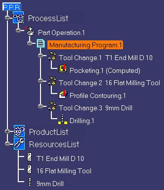
24 Generate NC Code This task shows you how to generate NC data in APT format from the program. For more information about this procedure please refer to Program Output. 1. Use the right mouse key on the Manufacturing Program.1 entity in the tree to select Manufacturing Program.1 object > Generate NC Code Interactively. The Generate NC Output Interactively dialog box appears.
25 2. Select APT as the desired NC data type. 3. Click Output File to select the folder where you want the file to be saved and specify the name of the file. 4. Click Execute to generate the APT source file. An extract from a typical APT source file is given below. $$ $$ Generated on Thursday, May 10, :58:20 PM $$ $$ Manufacturing Program.1 $$ Part Operation.1 $$*CATIA0 $$ Manufacturing Program.1 $$ $$ $$ PARTNO PART TO BE MACHINED COOLNT/ON CUTCOM/OFF PPRINT OPERATION NAME : Tool Change.1 $$ Start generation of : Tool Change.1 TLAXIS/ , , $$ TOOLCHANGEBEGINNING RAPID GOTO / , , CUTTER/ , , , , $, , TOOLNO/1, TPRINT/T1 End Mill D 10 LOADTL/1 $$ End of generation of : Tool Change.1 PPRINT OPERATION NAME : Pocketing.1 $$ Start generation of : Pocketing.1 FEDRAT/ ,MMPM SPINDL/ ,RPM,CLW GOTO / , , GOTO / , , GOTO / , , $$ End of generation of : Pocketing.1 PPRINT OPERATION NAME : Tool Change.2 $$ Start generation of : Tool Change.2 $$ TOOLCHANGEBEGINNING RAPID GOTO / , , CUTTER/ , , , , $, , TOOLNO/2, TPRINT/16 Flat Milling Tool LOADTL/2 $$ End of generation of : Tool Change.2 PPRINT OPERATION NAME : Profile Contouring.1 $$ Start generation of : Profile Contouring.1 FEDRAT/ ,MMPM SPINDL/ ,RPM,CLW GOTO / , , GOTO / , , $$ End of generation of : Profile Contouring.1 PPRINT OPERATION NAME : Tool Change.3
26 $$ Start generation of : Tool Change.3 $$ TOOLCHANGEBEGINNING RAPID GOTO / , , CUTTER/ , , , , $, , TOOLNO/3, TPRINT/9mm Drill LOADTL/3 $$ End of generation of : Tool Change.3 PPRINT OPERATION NAME : Drilling.1 $$ Start generation of : Drilling.1 LOADTL/3,1 SPINDL/ ,RPM,CLW RAPID GOTO / , , RAPID GOTO / , , CYCLE/DRILL, , , ,MMPM GOTO / , , GOTO / , , CYCLE/OFF RAPID GOTO / , , RAPID GOTO / , , $$ End of generation of : Drilling.1 SPINDL/OFF REWIND/0 END
27 User Tasks The tasks you will perform in the Prismatic Machining workbench involve creating, editing and managing machining operations and other Machining entities. Milling Operations 2.5 to 5-axis Drilling Operations Auxiliary Operations Features for Machining Part Operations, Manufacturing Programs, and Machining Processes NC Manufacturing Entities Verification, Simulation and Program Output The tasks dealing with the following Machining topics are documented in the NC Manufacturing Infrastructure User's Guide. Design Changes Set Up and Part Positioning MfgBatch Utility for Generating NC Data
28 Milling Operations The tasks in this section show you how to create 2.5 axis milling operations in your manufacturing program. Pocketing Operations Select the Pocketing icon then select the geometry to be machined (open or closed pocket, islands, and so on). Specify the tool to be used. Set parameters for axial and radial machining and other criteria such as finishing and high-speed milling. Set feeds and speeds and NC macros as needed. A Pocketing operation can be created for machining: Closed pockets Tool machines the area delimited by hard boundaries Open pockets Tool machines the area that has a least one soft boundary. Prismatic Roughing Operations Create a Prismatic Roughing Operation: Select the Prismatic Roughing icon then select the geometry to be rough machined and specify the tool to be used. Set parameters for axial and radial machining and other criteria such as high-speed milling. Set feeds and speeds and NC macros as needed. Facing Operations Create a Facing Operation: Select the Facing icon then select the geometry to be machined and specify the tool to be used. Set parameters for axial and radial machining and other criteria such as finishing and high-speed milling. Set feeds and speeds and NC macros as needed. Profile Contouring Operations Select the Profile Contouring icon then select the geometry to be machined and specify the tool to be used. Set parameters for axial and radial machining and other criteria such as finishing and high-speed milling. Set feeds and speeds and NC macros as needed. A Profile Contouring operation can be created for machining: Between two planes Tool follows contour between top and bottom planes while respecting user-defined geometry limitations and machining strategy parameters. Between two curves (P2 functionality) Tool follows trajectory defined by top and bottom guide curves while respecting user-defined geometry limitations and machining strategy parameters. Between a curve and surfaces (P2 functionality) Tool follows trajectory defined by a top guide curve and bottom surfaces while respecting user-
29 defined geometry limitations and machining strategy parameters. By flank contouring (P2 functionality) Tool flank machines vertical part surface while respecting user-defined geometry limitations and machining strategy parameters. Curve Following Operations Create a Curve Following Operation: Select the Curve Following icon then select the geometry to be machined and specify the tool to be used. Specify machining parameters and feeds and speeds as needed. Groove Milling Operations Create a Groove Milling Operation: Select the Groove Milling icon then select the geometry to be machined and specify the tool to be used. Specify machining parameters and feeds and speeds as needed. Point to Point Operations Create a Point to Point Operation: Select the Point to Point icon then define a sequence of elementary Goto Point, Goto Position and Go Delta tool motions. Specify the tool to be used, machining parameters, NC macros, and feeds and speeds as needed.
30 Create a Pocketing Operation for Machining Closed Pockets This task shows how to insert a Pocketing operation in the program when the pocket to be machined comprises hard boundaries only (that is, a closed pocket). To create the operation you must define: the Pocketing mode as Closed Pocket the geometry of the pocket to be machined the tool that will be used the parameters of the machining strategy the feedrates and spindle speeds the macros (transition paths). Open the PrismaticMilling01.CATPart document, then select Machining > Prismatic Machining from the Start menu. Make the Manufacturing Program current in the specification tree. 1. Select the Pocketing icon. A Pocketing entity along with a default tool is added to the program. The Pocketing dialog box appears directly at the Geometry tab page. This tab page includes a sensitive icon to help you specify the geometry to be machined.
31 The bottom and flanks of the icon are colored red indicating that this geometry is required for defining the pocket. All other pocket geometry is optional. Make sure that the Pocketing style is set to Closed Pocket. 2. Right click the red Bottom in the icon and select Contour Detection from the contextual menu. Click the red Bottom then select the desired pocket bottom in the 3D window. The pocket boundary is automatically deduced thanks to the Contour Detection setting. This is indicated by the highlighted Drive elements.

32 The bottom and flanks of the icon are now colored green indicating that this geometry is now defined. For parts containing islands, you can right click the red Bottom in the icon and select Island Detection from the contextual menu. This allows island boundaries to be deduced automatically. 3. Click the Top Plane in the icon then select the desired top element in the 3D window. 4. Set the following offsets: 1.5mm on hard boundary 0.25mm on bottom. If your part includes islands, you can specify different offsets on individual islands using the Offset on Island contextual command (right click the Island label in the 3D window). 5. Select the Strategy tab page and choose the desired tool path style: Inward helical, Outward helical or Back and forth.

33 You can then use the tab pages to set parameters for: Machining such as machining tolerance Radial strategy Axial strategy (number of levels = 3, for example) Finishing High speed milling. A tool is proposed by default when you create a machining operation. If the proposed tool is not suitable, just select the Tool tab page to specify the tool you want to use. This is described in Edit the Tool of an Operation. 6. Select the Feeds and Speeds tab page to specify the feedrates and spindle speeds for the 7. operation. Select the Macros tab page retract motion, for example). to specify the operation's transition paths (approach and In the Macro Management frame, right-click the Approach line and select the Activate contextual command. In the Current Macro Toolbox frame, select the Axial mode. A sensitive icon representing this approach motion is displayed. Double click the distance parameter in the sensitive icon and enter the desired value in the pop-up dialog box.
34 Repeat this procedure to specify the Retract motion. See Define Macros of an Operation for another example of specifying transition paths on a machining operation. Before accepting the operation, you should check its validity by replaying the tool path.

35 8. Click OK to create the operation.
.")
36 Create a Pocketing Operation for Machining Open Pockets This task shows how to insert a Pocketing operation in the program when the pocket to be machined comprises at least one soft boundary (that is, an open pocket). To create the operation you must define: the Pocketing mode as Open Pocket the geometry of the pocket to be machined the tool that will be used the parameters of the machining strategy the feedrates and spindle speeds the macros (transition paths). Open the PrismaticMilling02.CATPart document, then select Machining > Prismatic Machining from the Start menu. Make the Manufacturing Program current in the specification tree. 1. Select the Pocketing icon. A Pocketing entity along with a default tool is added to the program. The Pocketing dialog box appears directly at the Geometry tab page. This tab page includes a sensitive icon to help you specify the geometry to be machined.

37 The bottom and flanks of the icon are colored red indicating that this geometry is required for defining the pocket. All other pocket geometry is optional. Make sure that the Pocketing style is set to Open Pocket. 2. Right click the red Bottom in the icon and select Contour Detection from the contextual menu. Click the red Bottom then select the desired pocket bottom in the 3D window. The pocket boundary is automatically deduced thanks to the Contour Detection setting. This is indicated by the highlighted Drive elements. Hard boundaries are shown by full lines and soft boundaries by dashed lines. For edge selection only, you can change a boundary segment from hard to soft (or from soft to hard) by selecting the corresponding edge. You can also globally change segments from hard to soft and from soft to hard using the Swap Hardness Mode contextual command. The bottom and flanks of the icon are now colored green indicating that this geometry is now defined. For parts containing islands, you can right click the red Bottom in the icon and select Island Detection from the contextual menu. This allows island boundaries to be deduced automatically. 3. Click the Top Plane in the icon then select the desired top element in the 3D window. 4. Set the following offsets: 1.5mm on hard boundary 0.25mm on bottom. If your part includes islands, you can specify different offsets on individual islands using the Offset on Island contextual command (right click the Island label in the 3D window).
 Axial strategy (number of levels = 3, for example) Finishing")
38 5. Select the Strategy tab page and choose the desired tool path style: Inward helical, Outward helical or Back and forth. You can then use the tab pages to set parameters for: Machining such as machining tolerance Radial strategy (overhang = 50, for example) Axial strategy (number of levels = 3, for example) Finishing High speed milling. For Back and forth, you can modify the proposed machining direction and progression direction that are symbolized by arrows next to the machining axis system. Clicking the Machining direction arrow displays a dialog box for specifying the direction of paths. Clicking the Progression direction arrow reverses the overall direction of progression of the paths. 6. A tool is proposed by default when you want to create a machining operation. If the proposed tool is not suitable, just select the Tool tab page to specify the tool you want to use. This is described in Edit the Tool of an Operation. 7. Select the Feeds and Speeds tab page to specify the feedrates and spindle speeds for the operation.

39 8. Select the Macros tab page to specify the operation's transition paths (approach and retract motion, for example). In the Macro Management frame, right-click the Approach line and select the Activate contextual command. In the Current Macro Toolbox frame, select the Axial mode. An icon representing this approach motion is displayed. Double click the distance parameter in the sensitive icon and enter the desired value in the pop-up dialog box. Repeat this procedure to specify the Retract motion. See Define Macros of an Operation for another example of specifying transition paths on a machining operation.

40 9. Before accepting the operation, you should check its validity by replaying the tool path. 10. Click OK to create the operation.

41 Create a Prismatic Roughing Operation This task shows how to insert a Prismatic Roughing operation in the program. This type of operation allows you to quickly rough machine a part in a single operation. This is particularly useful for parts that include drafted pockets or multiple bottom pockets. To create the operation you must define: the geometry to be rough machined the tool that will be used the parameters of the machining strategy the feedrates and spindle speeds the macros (transition paths). Open the Multi_Pockets.CATPart document, then select Machining > Prismatic Machining from the Start menu. Make the Manufacturing Program current in the specification tree. 1. Select the Prismatic Roughing icon the program.. A Prismatic Roughing entity along with a default tool is added to The Prismatic Roughing dialog box appears directly at the Geometry tab page includes a sensitive icon to help you specify the operation's required and optional geometry.. This tab page The Part and Rough stock areas of the icon are colored red indicating that this geometry is required. All other geometry is optional. 2. Click the red Part area then select PartBody either in the specification tree or in the 3D window. 3. Click the red Rough stock area in the icon then select Rough Stock.1 either in the specification tree or in the 3D window. 4. Set a 1.0mm offset on part.
.")
42 The Part and Rough stock areas are now colored green indicating that this geometry is now defined. 5. Select the Strategy tab page. You can then use the tab pages to set parameters for: Machining Radial strategy Axial strategy High speed milling (HSM). In the strategy tab page, you can modify the proposed tool axis direction by clicking on the arrow in the sensitive icon. This displays a dialog box for specifying the tool axis. For a Back and forth tool path, you can modify the proposed machining direction by clicking on the arrow in the sensitive icon. This displays a dialog box for specifying the direction of paths. 6. A tool is proposed by default when you create a machining operation. If the proposed tool is not suitable, just select the Tool tab page to specify the tool you want to use. This is described in Edit the Tool of an Operation. Only end mills can be used in Prismatic Roughing operations. 7. Select the Feeds and Speeds tab page to specify the feedrates and spindle speeds for the operation. 8. Select the Macros tab page to specify the operation's transition paths (approach and retract motion, for example). 9. Before accepting the operation, check its validity by replaying the tool path.

43 10. Click OK to create the operation.

44 Create a Facing Operation This task shows how to insert a Facing operation in the program. To create the operation you must define: the geometry to be machined the tool that will be used the parameters of the machining strategy : the proposed tool path styles are: Inward helical, Back and forth, and One way the feedrates and spindle speeds the macros (transition paths). Open the PrismaticMilling01.CATPart document, then select Machining > Prismatic Machining from the Start menu. Make the Manufacturing Program current in the specification tree. 1. Select the Facing icon. A Facing entity along with a default tool is added to the program. The Facing dialog box appears directly at the Geometry tab page sensitive icon to help you specify the geometry to be machined.. This tab page includes a The part bottom and flanks in the icon are colored red indicating that this geometry is required for defining the operation. All other geometry is optional. 2. Right click the red Bottom in the icon and select Contour Detection from the contextual menu. Click the red Bottom then select the underside of the part in the 3D window. The part boundary is automatically deduced thanks to the Contour Detection option. This is indicated by the highlighted Drive elements.

45 The bottom and flanks of the icon are now colored green indicating that this geometry is now defined. 3. Select the Strategy tab page and choose the desired tool path style: Inward helical, Back and forth, or One way. You can then use the tab pages to set parameters for: Machining such as machining tolerance Radial strategy (see example) Axial strategy (number of levels = 1, for example) Finishing High speed milling (for Inward helical tool path style only). 4. Select the Tool tab page to replace the default tool by a more suitable one. 5. Select the Face Mill icon. A 50mm diameter face mill is proposed. You can adjust the parameters as required. See Edit the Tool of an Operation for more information about selecting tools. 6. Select the Feeds and Speeds tab page to specify the feedrates and spindle speeds for the operation.

46 7. Select the Macros tab page mode. to specify a return macro, which is necessary for the One Way In the Macro Management frame, right-click the Return in a Level Retract line and select the Activate contextual command. In the Current Macro Toolbox frame, select the Axial mode. An icon representing this retract motion is displayed. Double click the distance parameter in the sensitive icon and enter the desired value in the pop-up dialog box. Select the Return in a Level Approach line, the repeat the procedure to specify the approach motion. See Define Macros of an Operation for another example of specifying transition paths on a machining operation.
.")
47 Before accepting the operation, you should check its validity by replaying the tool path. 8. Click OK to create the operation. In this scenario the operation used the default start point (that is, the origin of the absolute axis system). If you want to define a different start point, you can click the start point symbol in the sensitive icon then select a point. Please note that the exact position of operation's start point may be different from your selected point. The program will choose the nearest point from a number of possible start positions.

48 Create a Profile Contouring Operation Between Two Planes This task shows how to insert a 'Between Two Planes' Profile Contouring operation in the program. To create the operation you must define: the Contouring mode as Between two planes the geometry to be machined the tool that will be used the parameters of the machining strategy the feedrates and spindle speeds the macros (transition paths). Open the PrismaticMilling01.CATPart document, then select the desired Machining workbench from the Start menu. Make the Manufacturing Program current in the specification tree. 1. Select the Profile Contouring icon. The Profile Contouring dialog box appears directly at the Geometry tab page. This page includes a sensitive icon to help you specify the geometry to be machined. Set the Contouring mode to Between Two Planes. The part bottom and flanks in the icon are colored red indicating that this geometry is required for defining the operation. All other geometry is optional.


49 2. Click the red bottom in the icon, then select the underside of the part in the 3D window. 3. Set the Bottom type to Soft by clicking the text, then set the Offset on Bottom to -5mm. 4. Click the red flank in the icon, then select the profile along the front edge of the part in the 3D window. 5. Right click Start to set this condition to Out. Click the first relimiting element in the icon, then select the horizontal edge at one end of the contour profile in the 3D window. 6. Right click Stop to set this condition to Out. Click the second relimiting element in the icon, then select the horizontal edge at the other end of the contour profile in the 3D window. 7. Click the check element in the icon, then select the top face of the green fixture in the 3D window. The bottom, guide, limit and check elements of the icon are now colored green indicating that this geometry is now defined. These are also indicated on the part. 8. Select the Strategy tab page and choose the desired tool path style. You can then use the tabs to set parameters for: Machining such as machining tolerance Stepover (see example) Finishing High Speed Milling.

50 Output type in the Machining tab page allows you to manage the generation of Cutter compensation (CUTCOM) instructions in the NC data output. See Reference section for more information. 9. A tool is proposed by default when you want to create a machining operation. If the proposed tool is not suitable, just select the Tool tab page to specify the tool you want to use. This is described in Edit the Tool of an Operation. 10. Select the Feeds and Speeds tab page to specify the feedrates and spindle speeds for the operation. 11. Check the validity of the operation by replaying the tool path. The specified operation uses a default linking macro to avoid collision with the selected fixture. You can optimize the linking macro and add approach and retract macros to the operation in the Macros tab page. Please note that if a user-defined linking macro is not collision free, a default linking macro is applied. For more information please refer to Define Macros of a Milling Operation. 12. Click OK to create the operation. A Collision Checking capability is available in the Geometry tab page, which allows collision checking between the tool and guide elements during macro motions. See Reference section for more information.
51 Create a Profile Contouring Operation Between Two Curves This task shows how to insert a 'Between Two Curves' Profile Contouring operation in the program. To create the operation you must define: the Contouring mode as Between Two Curves the geometry to be machined the tool that will be used the parameters of the machining strategy the feedrates and spindle speeds the macros (transition paths). This task also illustrates the capability to machine a discontinuous guiding curve. Open the PrismaticMilling02.CATPart document, then select the desired Machining workbench from the Start menu. Make the Manufacturing Program current in the specification tree. 1. Select the Profile Contouring icon. The Profile Contouring dialog box appears directly at the Geometry tab page. This page includes a sensitive icon to help you specify the geometry to be machined. Set the Contouring mode to Between Two Curves.
 select the three continuous edges of the")
52 The top guiding curve in the icon is colored red indicating that this geometry is required for defining the operation. All other geometry is optional. 2. Click the red guiding curve in the icon, then in the 3D window: select the three continuous edges on the top of the part as shown (Guide 1 in figure below) select the three continuous edges of the downward slope on the other side of the part as shown (Guide 2 in figure below). During the selection, answer No to the question about inserting a line. 3. Click the auxiliary guiding curve in the icon, then in the 3D window: select the three continuous edges of the downward slope the part as shown (Auxiliary Guide in figure below) select the three continuous bottom edges on the other side of the part as shown. During the selection, answer No to the question about inserting a line. 4. If needed, set offsets on the geometric elements. The guide and limit elements of the icon are now colored green indicating that this geometry is now defined. These are also indicated on the part.
 Finishing High Speed Milling. 6.")

53 5. Select the Strategy tab page and choose the desired tool path style. You can then use the tabs to set parameters for: Machining such as machining tolerance Stepover (see example) Finishing High Speed Milling. 6. In the Macros tab page you should add an appropriate Linking macro that will allow the tool to retract and approach the discontinuous guiding curves. This is described in Define Macros of an Operation. A tool is proposed by default when you want to create a machining operation. If the proposed tool is not suitable, just select the Tool tab page to specify the tool you want to use. This procedure for this is described in Edit the Tool of an Operation.

54 7. If needed, select the Feeds and Speeds tab page to specify the feedrates and spindle speeds for the operation. 8. Check the validity of the operation by replaying the tool path. Please note that the tool tip is shifted below the guiding curves by a distance equal to the tool corner radius. If you want the tool tip to exactly follow the guiding curves you should enter an appropriate Offset on Contour value. 9. Click OK to create the operation. A Collision Checking capability is available in the Geometry tab page, which allows collision checking between the tool and guide elements during macro motions. See Reference section for more information.
55 Create a Profile Contouring Operation Between a Curve and Surfaces This task shows how to insert a 'Between Curve and Surfaces' Profile Contouring operation in the program. To create the operation you must define: the Contouring mode as Between Curve and Surfaces the geometry to be machined the tool that will be used the parameters of the machining strategy the feedrates and spindle speeds the macros (transition paths). Open the PrismaticMilling02.CATPart document, then select the desired Machining workbench from the Start menu. Make the Manufacturing Program current in the specification tree. 1. Select the Profile Contouring icon. The Profile Contouring dialog box appears directly at the Geometry tab page. This page includes a sensitive icon to help you specify the geometry to be machined. Set the Contouring mode to Between Curve and Surfaces.

56 The top guiding curve and part bottom in the icon are colored red indicating that this geometry is required for defining the operation. All other geometry is optional. 2. Click the red bottom in the icon, then select the bottom surface of the part in the 3D window. 3. Click the top guiding curve in the icon, then select the top edge of the part in the 3D window. 4. Click the first relimiting element in the icon, then select a vertical edge at one end of the part in the 3D window. 5. Click the second relimiting element in the icon, then select the vertical edge at the other end of the part in the 3D window. 6. If needed, set offsets on the geometric elements. The guide and limit elements of the icon are now colored green indicating that this geometry is now defined. These are also indicated on the part.

57 7. Select the Strategy tab page and choose the desired tool path style. You can then use the tabs to set parameters for: Machining such as machining tolerance Stepover (see example below) Finishing High Speed Milling.

58 A tool is proposed by default when you want to create a machining operation. If the proposed tool is not suitable, just select the Tool tab page to specify the tool you want to use. This is described in Edit the Tool of an Operation. 8. Select the Feeds and Speeds tab page to specify the feedrates and spindle speeds for the operation. 9. Check the validity of the operation by replaying the tool path. You can add approach and retract motions to the operation in the Macros tab page Define Macros of an Operation. 10. Click OK to create the operation.. This is described in A Collision Checking capability is available in the Geometry tab page, which allows collision checking between the tool and guide elements during macro motions. See Reference section for more information.
59 Create a Profile Contouring Operation for Flank Contouring This task shows how to insert a 'Flank Contouring' Profile Contouring operation in the program. To create the operation you must define: the Contouring mode as Flank Contouring the geometry to be machined the tool that will be used the parameters of the machining strategy the feedrates and spindle speeds the macros (transition paths). Open the PrismaticMilling02.CATPart document, then select the desired Machining workbench from the Start menu. Make the Manufacturing Program current in the specification tree. 1. Select the Profile Contouring icon. The Profile Contouring dialog box appears directly at the Geometry tab page. This page includes a sensitive icon to help you specify the geometry to be machined. Set the Contouring mode to By Flank Contouring.

60 The guiding element in the icon is colored red indicating that this geometry is required for defining the operation. All other geometry is optional. 2. Click the guiding element in the icon, then select the vertical face of the part in the 3D window. 3. Click the first relimiting element in the icon, then select a vertical edge at one end of the part in the 3D window. 4. Click the second relimiting element in the icon, then select the vertical edge at the other end of the part in the 3D window. The guide and limit elements of the icon are now colored green indicating that this geometry is now defined. These are also indicated on the part. 5. If needed, set offsets on the geometric elements.

61 6. Select the Strategy tab page and choose the desired tool path style. You can then use the tabs to set parameters for: Machining such as machining tolerance Stepover (see example below) Finishing. A tool is proposed by default when you want to create a machining operation. If the proposed tool is not suitable, just select the Tool tab page to specify the tool you want to use. This is described in Edit the Tool of an Operation. 7. Select the Feeds and Speeds tab page to specify the feedrates and spindle speeds for the operation. 8. Check the validity of the operation by replaying the tool path.

62 You can add approach and retract motions to the operation in the Macros tab page described in Define Macros of an Operation. 9. Click OK to create the operation.. This is A Collision Checking capability is available in the Geometry tab page, which allows collision checking between the tool and guide elements during macro motions. See Reference section for more information.
.")
63 Create a Curve Following Operation This task shows how to insert a Curve Following operation in the program. To create the operation you must define: the geometry to be machined the tool that will be used the parameters of the machining strategy the feedrates and spindle speeds the macros (transition paths). Open the PrismaticMilling02.CATPart document, then select the desired Machining workbench from the Start menu. Make the Manufacturing Program current in the specification tree. 1. Select the Curve Following icon. The Curve Following dialog box appears directly at the Geometry tab page. This page includes a sensitive icon to help you specify the geometry to be machined. The guiding curve in the icon is colored red indicating that this geometry is required for defining the operation. All other geometry is optional. 2. Click the guiding curve in the icon, then select the desired curve in the 3D window. 3. If needed, set an axial offset on the guiding curve. The guide element of the icon is now colored green indicating that this geometry is now defined. It is also indicated on the part.

64 4. Select the Strategy tab page to specify parameters for: Machining Axial. Set the main strategy parameters as shown. A tool is proposed by default when you want to create a machining operation. If the proposed tool is not suitable, just select the Tool tab page to specify the tool you want to use. This is described in Edit the Tool of an Operation. 5. Select the Feeds and Speeds tab page to specify the feedrates and spindle speeds for the operation.

65 6. Check the validity of the operation by replaying the tool path. You can add approach and retract motions to the operation in the Macros tab page. This is described in Define Macros of an Operation. 7. Click OK to create the operation.
.")
66 Create a Groove Milling Operation This task shows how to insert a Groove Milling operation in the program. To create the operation you must define: the geometry to be machined the tool that will be used the parameters of the machining strategy the feedrates and spindle speeds the macros (transition paths). Open the sample_groove_milling.catpart document, then select the desired Machining workbench from the Start menu. Make the Manufacturing Program current in the specification tree. 1. Select the Groove Milling icon. The Groove Milling dialog box appears directly at the Geometry tab page geometry to be machined.. This page includes a sensitive icon to help you specify the The groove top, bottom and flank in the icon are colored red indicating that this geometry is required for defining the operation. All other geometry is optional. Note that Contour Detection contextual command is not activated. 2. Click the red bottom in the icon, then select the bottom of the groove in the 3D window. 3. Click the red top in the icon, then select the top of the groove in the 3D window.

67 4. Click the red guiding element in the icon, then select the flank contour of the groove in the 3D window. If the Contour Detection contextual command is set, the boundary of the selected face will be proposed automatically as guiding contour. See Specifying Guiding Contours for more information. 5. Right click Start to set this condition to Out. Click the first relimiting element in the icon, then select the horizontal edge at one end of the contour profile in the 3D window. Set the Offset on Limit1 to 5mm. 6. Right click Stop to set this condition to Out. Click the second relimiting element in the icon, then select the horizontal edge at the other end of the contour profile in the 3D window. Set the Offset on Limit2 to 5mm. See Specifying Relimiting Elements for more information. The bottom, guide, limit and check elements of the icon are now colored green indicating that this geometry is now defined. These are also indicated on the part. 7. Select the Strategy tab page and choose the desired tool path style. You can then use the tabs to set parameters for: Machining Axial/Radial stepover, such as:

68 Finishing. 8. A tool is proposed by default when you want to create a machining operation. If the proposed tool is not suitable, just select the Tool tab page to specify the tool you want to use. This is described in Edit the Tool of an Operation. 9. Select the Feeds and Speeds tab page to specify the feedrates and spindle speeds for the operation. 10. Check the validity of the operation by replaying the tool path.

69 The specified operation uses a default Return between levels macro to allow switching compensation points for machining upper and lower levels of the groove. You can optimize this macro and add approach and retract macros to the operation in the Macros tab page. This is described in Define Macros of a Milling Operation. 11. Click OK to create the operation. A Collision Checking capability is available in the Geometry tab page, which allows collision checking between the tool and guide elements during macro motions. See Reference section for more information.
70 Create a Point to Point Operation This task shows how to insert a Point to Point operation in the program. To create the operation you must define: a sequence of elementary tool motions and machining strategy parameters the tool that will be used the feedrates and spindle speeds the macros (transition paths). Open the PrismaticMilling02.CATPart document, then select Machining > Prismatic Machining from the Start menu. Make the Manufacturing Program current in the specification tree. 1. Select the Point to Point icon. A Point to Point entity along with a default tool is added to the program. 2. The Point to Point dialog box appears directly at the Strategy tab page. This Motions tab allows you to define the elementary Goto Point, Goto Position and Go Delta motions making up the machining operation. Click the Goto Point icon, then select a corner point on the underside of the part. 3. Just double-click to end point selection. The first tool motion is defined and appears in the list in the dialog box. Click the Goto Position icon. A dialog box appears to help you specify the part, drive and check elements as well as positioning conditions (To / On / Past).

71 4. Just click OK when you have specified the desired elements and conditions. The second tool motion is defined and appears in the list in the dialog box. 5. Add other Goto Point, Goto Position and Go Delta motions as shown in the figure below.

72 In this dialog box you can: add PP words to the list by clicking on the PP words icon and specifying the desired syntax. move motions up or down the list by the Arrow icons or remove motions by means of the Remove icon. edit the properties of a motion by clicking the Properties icon. 6. Select the Strategy tab to specify machining parameters. If needed, double click the sensitive text in the icon to specify an offset along the tool axis. Define the tool axis direction by first selecting the axis representation in the sensitive icon then specifying the direction in the dialog box that appears. 7. Select the Tool tab page to replace the default tool by a more suitable one. Select the Face Mill icon. A 50mm diameter face mill is proposed. You can adjust the parameters as required. See Edit the Tool of an Operation for more information about selecting tools. Check the validity of the operation by replaying the tool path.

73 8. Select the Feeds and Speeds tab page to specify the feedrates and spindle speeds for the operation. 9. If you want to specify approach and retract motion for the operation, select the Macros tab page to specify the desired transition paths. The general procedure for this is described in Define Macros of an Operation. 10. Click OK to create the operation. You can use the contextual menu commands to insert or remove points and to assign local feedrates. By selecting a circle, its center is taken as the point to machine. Points of an associated sketch can also be selected. Points can be defined by indicating on a user-defined plane. Points can be defined by means of X, Y, Z coordinates in the machining axis system.
74 2.5 to 5-axis Drilling Operations The drilling (or axial machining) operations described in this section are intended to cover the hole making activities in your manufacturing program. Spot Drilling Operation Create a Spot Drilling Operation: Select the Spot Drilling icon then select the positions to be spot drilled and specify the tool to be used. Specify the depth mode (By Tip or By Diameter). Finally, set the other machining parameters, macros, and feeds and speeds as needed. Drilling Operations Create a Drilling Operation: Select the Drilling icon then select the hole or hole pattern to be drilled and specify the tool to be used. Specify the depth mode (By Tip or By Shoulder). Finally, set the other machining parameters, macros, and feeds and speeds as needed. Create a Drilling Dwell Delay Operation: Select the Drilling Dwell Delay icon then select the hole or hole pattern to be drilled and specify the tool to be used. Specify the depth mode (By Tip or By Shoulder) and the dwell duration. Finally, set the other machining parameters, macros, and feeds and speeds as needed. Create a Drilling Deep Hole Operation: Select the Drilling Deep Hole icon then select the hole or hole pattern to be drilled and specify the tool to be used. Specify the depth mode (By Tip or By Shoulder). Finally, set the other machining parameters, macros, and feeds and speeds as needed. Create a Drilling Break Chips Operation: Select the Drilling Break Chips icon then select the hole or hole pattern to be drilled and specify the tool to be used. Specify the depth mode (By Tip or By Shoulder). Finally, set the other machining parameters, macros, and feeds and speeds as needed. Hole Finishing Operations Create a Reaming Operation: Select the Reaming icon then select the hole or hole pattern to be machined and specify the tool to be used. Specify the depth mode (By Tip or By Shoulder). Finally, set the other machining parameters, macros, and feeds and speeds as needed. Create a Counterboring Operation: Select the Counterboring icon then select the hole or hole pattern to be machined and specify the tool to be used. Specify the depth mode (By Tip or By Shoulder). Finally, set the other machining parameters, macros, and feeds and speeds as needed. Boring Operations Create a Boring Operation: Select the Boring icon then select the hole or hole pattern to be machined and specify the tool to be used. Specify the depth mode (By Tip or By Shoulder). Finally, set the other machining parameters, macros, and feeds and speeds as needed. Create a Boring Spindle Stop Operation: Select the Boring Spindle Stop icon then select the hole or hole pattern to be machined and specify the tool to be used. Specify the depth mode (By Tip or By Shoulder) and the amount of tool shift away from the bored hole. Finally, set the other machining parameters, macros, and feeds and speeds as needed. Create a Boring and Chamfering Operation: Select the Boring and Chamfering icon then select the hole or hole pattern to be machined and specify the tool to be used. Specify the depth mode (By Tip or By Shoulder). Finally, for the boring and chamfering phases set the machining parameters, macros, and feeds and speeds as needed.
75 Create a Back Boring Operation: Select the Back Boring icon then select the hole or hole pattern to be machined and specify the tool to be used. Specify the depth mode (By Tip or By Shoulder) and the amount of tool shift for back boring. Finally, set the other machining parameters, macros, and feeds and speeds as needed. Threading Operations Create a Tapping Operation: Select the Tapping icon then select the hole or hole pattern to be machined and specify the tool to be used. Specify the depth mode (By Tip or By Shoulder). Finally, set the other machining parameters, macros, and feeds and speeds as needed. Create a Reverse Threading Operation: Select the Reverse Threading icon then select the hole or hole pattern to be machined and specify the tool to be used. Specify the depth mode (By Tip or By Shoulder). Finally, set the other machining parameters, macros, and feeds and speeds as needed. Create a Thread without Tap Head Operation: Select the Thread without Tap Head icon then select the hole or hole pattern to be machined and specify the tool to be used. The By Tip depth mode is imposed for this operation. Finally, set the other machining parameters, macros, and feeds and speeds as needed. Create a Thread Milling Operation: Select the Thread Milling icon then select the hole or hole pattern to be machined and specify the tool to be used. Finally, set the other machining parameters, macros, and feeds and speeds as needed. Countersinking and Chamfering Operations Create a Countersinking Operation: Select the Countersinking icon then select the hole or hole pattern to be machined and specify the tool to be used. Specify the depth mode (By Distance or By Diameter). Finally, set the other machining parameters, macros, and feeds and speeds as needed. Create a Chamfering Two Sides Operation: Select the Chamfering Two Sides icon then select the hole or hole pattern to be machined and specify the tool to be used. The By Tip depth mode is imposed for this operation. Finally, set the other machining parameters, macros, and feeds and speeds as needed. T-Slotting and Circular Milling Create a T-Slotting Operation: Select the T-Slotting icon then select the hole or hole pattern to be machined and specify the tool to be used. The By Tip depth mode is imposed for this operation. Finally, set the other machining parameters, macros, and feeds and speeds as needed. Create a Circular Milling Operation: Select the Circular Milling icon then select the hole or hole pattern to be machined and specify the tool to be used. Specify the machining mode (Standard or Helical). Finally, set the other machining parameters, macros, and feeds and speeds as needed.


76 Create a Spot Drilling Operation This task shows how to insert a Spot Drilling operation in the program. To create the operation you must define: the geometry of the holes to be machined the tool that will be used the parameters of the machining strategy the feedrates and spindle speeds the macros (transition paths). Open the HoleMakingOperations.CATPart document, then select the desired Machining workbench from the Start menu. Make the Manufacturing Program current in the specification tree. 1. Select the Spot Drilling icon. A Spot Drilling entity along with a default tool is added to the program. The Spot Drilling dialog box appears directly at the Geometry tab page representing a simple hole. There are several hot spots in the icon. 2. Select red hole depth representation, then select the points to be spot drilled. You can do this by selecting the circular edges of holes. In this case, the circle centers are taken as the points to be spot drilled. Just double click to end your selections.. This tab page includes an icon 3. If needed, click on the tool axis symbol to invert the tool axis direction.

77 4. Select the Strategy tab page to specify the following machining parameters: approach clearance depth mode: by diameter The diameter value used is the one specified in the geometry tab page. dwell compensation number depending on those available on the tool. The other parameters are optional in this case. 5. A tool is proposed by default when you want to create a machining operation. Drills, Multi-diameter Drills, Spot Drills, and Center Drills can be used. Conical Mills can also be used. If the proposed tool is not suitable, just select the Tool tab page described in Edit the Tool of an Operation. to specify the tool you want to use. This is 6. Select the Feeds and Speeds tab page to specify the feedrates and spindle speeds for the operation. Note that in the tool path represented in the strategy page, tool motion is as follows: Motion at machining feedrate from 1 to 2 Dwell for the specified duration Retract at retract feedrate from 2 to If you want to specify approach and retract motion for the operation, select the Macros tab page to specify the desired transition paths. The general procedure for this is described in Define Macros of an Axial Machining Operation. 8. Before accepting the operation, you should check its validity by replaying the tool path. 9. Click OK to create the operation.
78 Example of output If your PP table is customized with the following statement for Spot Drilling operations: CYCLE/SPDRL, %MFG_TOTAL_DEPTH, %MFG_FEED_MACH_VALUE, &MFG_FEED_UNIT, %MFG_CLEAR_TIP, DWELL, %MFG_DWELL_REVOL A typical NC data output is as follows: CYCLE/SPDRL, , , MMPM, , DWELL, 3 You can use the Edit Cycle icon Cycle Syntaxes in Axial Machining Operations. to edit or choose output syntaxes. For more information please refer to Editing The parameters available for PP word syntaxes for this type of operation are described in the NC_SPOT_DRILLING section of the Manufacturing Infrastructure User's Guide.
79 Create a Drilling Operation This task shows how to insert a Drilling operation in the program. To create the operation you must define: the geometry of the holes to be machined the tool that will be used the parameters of the machining strategy the feedrates and spindle speeds the macros (transition paths). Open the HoleMakingOperations.CATPart document, then select the desired Machining workbench from the Start menu. Make the Manufacturing Program current in the specification tree. 1. Select the Drilling icon. A Drilling entity along with a default tool is added to the program. The Drilling dialog box appears directly at the Geometry tab page. This tab page includes a sensitive icon to help you specify the geometry of the hole or hole pattern to be machined. 2. Select the red hole depth representation then select the pattern of 10 holes as shown below. Just double click to end your selections.
80 The sensitive icon is updated with the following information: depth and diameter of the first selected feature hole extension type: through hole number of points to machine. 3. If needed, you can invert the tool axis direction by selecting the axis representation in the sensitive icon. 4. If needed, you can define a clearance by first double clicking the Jump Distance parameter in the sensitive icon then specifying a value in the Edit Parameter dialog box that appears.
81 5. Select the Strategy tab page to specify the following machining parameters: Approach clearance Depth mode: by tip The depth value used is the one specified in the Geometry tab page. Breakthrough distance Compensation number depending on those available on the tool. The other parameters are optional in this case. A tool is proposed by default when you want to create a machining operation. If the proposed tool is not suitable, just select the Tool tab page want to use. This is described in Edit the Tool of an Operation. to specify the tool you Remember that you can make use of the hole diameter found on the selected hole feature to select an appropriate tool. 6. Select the Feeds and Speeds tab page to specify the feedrates and spindle speeds for the operation. Note that in the Drilling tool path represented in the strategy page, tool motion is as follows: machining feedrate from 1 to 2 retract or rapid feedrate from 2 to If you want to specify approach and retract motion for the operation, select the Macros tab page to specify the desired transition paths. The general procedure for this is described in Define Macros of an Axial Machining Operation. Before accepting the operation, you should check its validity by replaying the tool path. 8. Click OK to create the operation.
82 Example of output If your PP table is customized with the following statement for Drilling operations: CYCLE/DRILL, %MFG_TOTAL_DEPTH, %MFG_FEED_MACH_VALUE, &MFG_FEED_UNIT, %MFG_CLEAR_TIP A typical NC data output is as follows: CYCLE/DRILL, , , MMPM, You can use the Edit Cycle icon to edit or choose output syntaxes. For more information please refer to Editing Cycle Syntaxes in Axial Machining Operations. The parameters available for PP word syntaxes for this type of operation are described in the NC_DRILLING section of the Manufacturing Infrastructure User's Guide.

83 Create a Drilling Dwell Delay Operation This task shows how to insert a Drilling Dwell Delay operation in the program. To create the operation you must define: the geometry of the holes to be machined the tool that will be used the parameters of the machining strategy the feedrates and spindle speeds the macros (transition paths). Open the HoleMakingOperations.CATPart document, then select the desired Machining workbench from the Start menu. Make the Manufacturing Program current in the specification tree. 1. Select the Drilling Dwell Delay icon. A Drilling Dwell Delay entity along with a default tool is added to the program. The Drilling Dwell Delay dialog box appears directly at the Geometry tab page. This tab page includes a sensitive icon to help you specify the geometry of the hole or hole pattern to drill. 2. Select the red hole depth representation then select the hole feature as shown. Just double click to end your selection. The sensitive icon is updated with the following information: depth and diameter of the selected hole hole extension type: blind.

84 3. If needed, you can invert the tool axis direction by selecting the axis representation in the sensitive icon. 4. Select the Strategy tab page to specify the following machining parameters: Approach clearance Depth mode: by shoulder The depth value used is the one specified in the Geometry tab page. Dwell delay Compensation number depending on those available on the tool. The other parameters are optional in this case.

85 A tool is proposed by default when you want to create a machining operation. If the proposed tool is not suitable, just select the Tool tab page want to use. to specify the tool you Remember that you can make use of the hole diameter found on the selected hole feature to select an appropriate tool. This is described in Edit the Tool of an Operation. 5. Select the Feeds and Speeds tab page to specify the feedrates and spindle speeds for the operation. Note that in the tool path represented in the strategy page, tool motion is as follows: machining feedrate from 1 to 2 dwell for the specified duration retract or rapid feedrate from 2 to 3. 6 If you want to specify approach and retract motion for the operation, select the Macros tab page to specify the desired transition paths. The general procedure for this is described in Define Macros of an Axial Machining Operation.
86 Before accepting the operation, you should check its validity by replaying the tool path. 7. Click OK to create the operation. Example of output If your PP table is customized with the following statement for Drilling Dwell Delay operations: CYCLE/DRILL, %MFG_TOTAL_DEPTH, %MFG_FEED_MACH_VALUE, &MFG_FEED_UNIT, %MFG_CLEAR_TIP, DWELL, %MFG_DWELL_REVOL A typical NC data output is as follows: CYCLE/DRILL, , , MMPM, , DWELL, 3 You can use the Edit Cycle icon to edit or choose output syntaxes. For more information please refer to Editing Cycle Syntaxes in Axial Machining Operations. The parameters available for PP word syntaxes for this type of operation are described in the NC_DRILLING_DWELL_DELAY section of the Manufacturing Infrastructure User's Guide.
87 Create a Drilling Deep Hole Operation This task shows how to insert a Drilling Deep Hole operation in the program. To create the operation you must define: the geometry of the holes to be machined the tool that will be used the parameters of the machining strategy the feedrates and spindle speeds the macros (transition paths). Open the HoleMakingOperations.CATPart document, then select the desired Machining workbench from the Start menu. Make the Manufacturing Program current in the specification tree. 1. Select the Drilling Deep Hole icon. A Drilling Deep Hole entity along with a default tool is added to the program. The Drilling Deep Hole dialog box appears directly at the Geometry tab page sensitive icon to help you specify the geometry of the hole or hole pattern to be machined. 2. Select the red hole depth representation then select the hole features as shown below. Just double click to end your selections.. This tab page includes a The sensitive icon is updated with the following information: depth and diameter of the first selected hole hole extension type: through number of points to machine. 3. If needed, you can invert the tool axis direction by selecting the axis representation in the sensitive icon.

88 4. Select the Strategy tab page to specify the following machining parameters: Approach clearance Depth mode: by tip The depth value used is the one specified in the Geometry tab page. Breakthrough distance Maximum depth of cut and retract offset Decrement rate and Decrement limit Dwell mode Compensation number depending on those available on the tool. The other parameters are optional in this case. A tool is proposed by default when you want to create a machining operation. If the proposed tool is not suitable, just select the Tool tab page to specify the tool you want to use. Remember that you can make use of the hole diameter found on the selected hole feature to select an appropriate tool. This is described in Edit the Tool of an Operation. 5. Select the Feeds and Speeds tab page to specify the feedrates and spindle speeds for the operation. Note that in the tool path represented in the strategy page, tool motion is as follows: Motion at machining feedrate from 1 to 2 Dwell for specified duration Retract at retract feedrate from 2 to 3 Motion at plunge feedrate from 3 to 4 Motion at machining feedrate from 4 to 5 Dwell for specified duration Retract at retract feedrate from 5 to 6 Motion at plunge feedrate from 6 to 7 Motion at machining feedrate from 7 to 8 Dwell for specified duration Retract at retract feedrate from 8 to 9
89 Distance (1,2) = A + Dc Distance (3,4) = A + Dc - Or Distance (4,5) = Or + Dc*(1 - decrement rate) Distance (7,8) = Or + Dc*(1-2*decrement rate). Also note that: Depth of current peck > Maximum depth of cut * Decrement limit. For more information see Example of Decrement rate and Decrement limit. 6. If you want to specify approach and retract motion for the operation, select the Macros tab page to specify the desired transition paths. The general procedure for this is described in Define Macros of an Axial Machining Operation. 7. Before accepting the operation, check its validity by replaying the tool path. 8. Click OK to create the operation. Example of output If your PP table is customized with the following statement for Drilling Deep Hole operations: CYCLE/DEEPHL,%MFG_TOTAL_DEPTH,INCR,%MFG_AXIAL_DEPTH,%MFG_FEED_MACH_VALUE, &MFG_FEED_UNIT,%MFG_CLEAR_TIP,DWELL,%MFG_DWELL_REVOL A typical NC data output is as follows: CYCLE/DEEPHL, , INCR, , , MMPM, , DWELL, 3 You can use the Edit Cycle icon Cycle Syntaxes in Axial Machining Operations. to edit or choose output syntaxes. For more information please refer to Editing The parameters available for PP word syntaxes for this type of operation are described in the NC_DEEPHOLE section of the Manufacturing Infrastructure User's Guide.

90 Create a Drilling Break Chips Operation This task shows how to insert a Drilling Break Chips operation in the program. To create the operation you must define: the geometry of the holes to be machined the tool that will be used the parameters of the machining strategy the feedrates and spindle speeds the macros (transition paths). Open the HoleMakingOperations.CATPart document, then select the desired Machining workbench from the Start menu. Make the Manufacturing Program current in the specification tree. 1. Select the Drilling Break Chips icon. A Drilling Break Chips entity along with a default tool is added to the program. The Drilling Break Chips dialog box appears directly at the Geometry tab page sensitive icon to help you specify the geometry of the hole or hole pattern to be machined. 2. Select the red hole depth representation then select the hole feature as shown below. Just double click to end your selections.. This tab page includes a The sensitive icon is updated with the following information: depth and diameter of the selected hole hole extension type: through. 3. If needed, you can invert the tool axis direction by selecting the axis representation in the sensitive icon.

91 4. Select the Strategy tab page to specify the following machining parameters: Approach clearance Depth mode: by tip The depth value used is the one specified in the geometry tab page. Breakthrough distance Maximum depth of cut and retract offset Dwell Compensation number depending on those available on the tool. The other parameters are optional in this case. A tool is proposed by default when you want to create a machining operation. If the proposed tool is not suitable, just select the Tool tab page to specify the tool you want to use. Remember that you can make use of the hole diameter found on the selected hole feature to select an appropriate tool. This is described in Edit the Tool of an Operation. 5. Select the Feeds and Speeds tab page to specify the feedrates and spindle speeds for the operation. Note that in the tool path represented in the strategy page, tool motion is as follows: Motion at machining feedrate from 1 to 2 Dwell for specified duration Retract at retract feedrate from 2 to 3 Motion at machining feedrate from 3 to 4 Dwell for specified duration Retract at retract feedrate from 4 to 5 Motion at machining feedrate from 5 to 6 Dwell for specified duration Retract at retract feedrate from 6 to 7 Distance (1,2) = A + Dc Distance (2,3) = Distance (4,5) = Or
92 Distance (3,4) = Distance (5,6) = Or + Dc 6. If you want to specify approach and retract motion for the operation, select the Macros tab page to specify the desired transition paths. The general procedure for this is described in Define Macros of an Axial Machining Operation. Before accepting the operation, you should check its validity by replaying the tool path. 7. Click OK to create the operation. Example of output If your PP table is customized with the following statement for Drilling Break Chips operations: CYCLE/BRKCHP,%MFG_TOTAL_DEPTH,INCR,%MFG_AXIAL_DEPTH,%MFG_FEED_MACH_VALUE, &MFG_FEED_UNIT, %MFG_CLEAR_TIP,DWELL,%MFG_DWELL_REVOL A typical NC data output is as follows: CYCLE/BRKCHP, , INCR, , , MMPM, , DWELL, 3 You can use the Edit Cycle icon Cycle Syntaxes in Axial Machining Operations. to edit or choose output syntaxes. For more information please refer to Editing The parameters available for PP word syntaxes for this type of operation are described in the NC_BREAK_CHIPS section of the Manufacturing Infrastructure User's Guide.
93 Create a Reaming Operation This task shows how to insert a Reaming operation in the program. To create the operation you must define: the geometry of the holes to be machined the tool that will be used the parameters of the machining strategy the feedrates and spindle speeds the macros (transition paths). Open the HoleMakingOperations.CATPart document, then select the desired Machining workbench from the Start menu. Make the Manufacturing Program current in the specification tree. 1. Select the Reaming icon. A Reaming entity along with a default tool is added to the program. The Reaming dialog box appears directly at the Geometry tab page. This tab page includes a sensitive icon to help you specify the geometry of the hole or hole pattern to be machined. 2. Select the red hole depth representation then select the pattern of 10 holes. Just double click to end your selections. The sensitive icon is updated with the following information: depth and diameter of the first selected feature hole extension type: through hole number of points to machine. 3. If needed, you can invert the tool axis direction by selecting the axis representation in the sensitive icon.
 Compensation number depending on those available on the tool. The other parameters are optional in this case.")
94 4. Select the Strategy tab page to specify the following machining parameters: Approach clearance Depth mode: by shoulder The depth value used is the one specified in the Geometry tab page. Dwell (in seconds) Compensation number depending on those available on the tool. The other parameters are optional in this case. A tool is proposed by default when you want to create a machining operation. If the proposed tool is not suitable, just select the Tool tab page want to use. This is described in Edit the Tool of an Operation. to specify the tool you 5. Select the Feeds and Speeds tab page to specify the feedrates and spindle speeds for the operation. Note that in the tool path represented in the strategy page, tool motion is at: Motion at machining feedrate from 1 to 2 Dwell for specified duration Retract at retract feedrate from 2 to If you want to specify approach and retract motion for the operation, select the Macros tab page to specify the desired transition paths. The general procedure for this is described in Define Macros of an Axial Machining Operation. Before accepting the operation, you should check its validity by replaying the tool path.
95 7. Click OK to create the operation. Example of output If your PP table is customized with the following statement for Reaming operations: CYCLE/REAM, %MFG_TOTAL_DEPTH, %MFG_FEED_MACH_VALUE, &MFG_FEED_UNIT, %MFG_CLEAR_TIP, DWELL, %MFG_DWELL_REVOL A typical NC data output is as follows: CYCLE/REAM, , , MMPM, , DWELL, 3 You can use the Edit Cycle icon to edit or choose output syntaxes. For more information please refer to Editing Cycle Syntaxes in Axial Machining Operations. The parameters available for PP word syntaxes for this type of operation are described in the NC_REAMING section of the Manufacturing Infrastructure User's Guide.

96 Create a Counterboring Operation This task shows how to insert a Counterboring operation in the program. To create the operation you must define: the geometry of the holes to be machined the tool that will be used the parameters of the machining strategy the feedrates and spindle speeds the macros (transition paths). Open the HoleMakingOperations.CATPart document, then select the desired Machining workbench from the Start menu. Make the Manufacturing Program current in the specification tree. 1. Select the Counterboring icon. A Counterboring entity along with a default tool is added to the program. The Counterboring dialog box appears directly at the Geometry tab page. 2. Select the red hole depth representation then select hole geometry in the 3D window. Just double click to end your selection. 3. If needed, you can invert the tool axis direction by selecting the axis representation in the sensitive icon.

97 4. Select the Strategy tab page and specify the following machining parameters: Approach clearance Depth mode: by tip The depth value used is the one specified in the Geometry tab page. Dwell Compensation number depending on those available on the tool. The other parameters are optional in this case. A tool is proposed by default when you want to create a machining operation. If the proposed tool is not suitable, just select the Tool tab page want to use. This is described in Edit the Tool of an Operation. to specify the tool you 5. Select the Feeds and Speeds tab page to specify the feedrates and spindle speeds for the operation. Note that in the toolpath represented in the strategy page, tool motion is at: Motion at machining feedrate from 1 to 2 Dwell for specified duration Retract at retract feedrate from 2 to If you want to specify approach and retract motion for the operation, select the Macros tab page to specify the desired transition paths. The general procedure for this is described in Define Macros of an Axial Machining Operation. Before accepting the operation, you should check its validity by replaying the tool path. 7. Click OK to create the operation.
98 Example of output If your PP table is customized with the following statement for Counterboring operations: CYCLE/CBORE, %MFG_TOTAL_DEPTH, %MFG_FEED_MACH_VALUE, &MFG_FEED_UNIT, %MFG_CLEAR_TIP, DWELL, %MFG_DWELL_REVOL A typical NC data output is as follows: CYCLE/CBORE, , , MMPM, , DWELL, 3 You can use the Edit Cycle icon to edit or choose output syntaxes. For more information please refer to Editing Cycle Syntaxes in Axial Machining Operations. The parameters available for PP word syntaxes for this type of operation are described in the NC_COUNTERBORING section of the Manufacturing Infrastructure User's Guide.
99 Create a Boring Operation This task shows how to insert a Boring operation in the program. To create the operation you must define: the geometry of the holes to be machined the tool that will be used the parameters of the machining strategy the feedrates and spindle speeds the macros (transition paths). Open the HoleMakingOperations.CATPart document, then select the desired Machining workbench from the Start menu. Make the Manufacturing Program current in the specification tree. 1. Select the Boring icon. A Boring entity along with a default tool is added to the program. The Boring dialog box appears directly at the Geometry tab page. 2. Select the red hole depth representation then select the pattern of 10 holes. Just double click to end your selections. The sensitive icon is updated with the following information: depth and diameter of the first selected feature hole extension type: through hole number of points to machine. 3. If needed, you can invert the tool axis direction by selecting the axis representation in the sensitive icon.

100 4. Select the Strategy tab page to specify the following machining parameters: approach clearance depth mode: by tip The depth value used is the one specified in the Geometry tab page breakthrough distance dwell compensation number depending on those available on the tool. The other parameters are optional in this case. 5 A tool is proposed by default when you want to create a machining operation. If the proposed tool is not suitable, just select the Tool tab page want to use. This is described in Edit the Tool of an Operation. to specify the tool you 6. Select the Feeds and Speeds tab page to specify the feedrates and spindle speeds for the operation. Note that in the tool path represented in the strategy page, tool motion is as follows: Motion at machining feedrate from 1 to 2 Dwell for specified duration Retract at retract feedrate from 2 to If you want to specify approach and retract motion for the operation, select the Macros tab page to specify the desired transition paths. The general procedure for this is described in Define Macros of an Axial Machining Operation. 8. Before accepting the operation, you should check its validity by replaying the tool path. Note that Boring Bars are supported for Photo and Video material removal simulations.
101 9. Click OK to create the operation. Example of output If your PP table is customized with the following statement for Boring operations: CYCLE/BORE, %MFG_TOTAL_DEPTH, %MFG_FEED_MACH_VALUE, &MFG_FEED_UNIT, %MFG_CLEAR_TIP, DWELL, %MFG_DWELL_REVOL A typical NC data output is as follows: CYCLE/BORE, , , MMPM, , DWELL, 3 You can use the Edit Cycle icon to edit or choose output syntaxes. For more information please refer to Editing Cycle Syntaxes in Axial Machining Operations. The parameters available for PP word syntaxes for this type of operation are described in the NC_BORING section of the Manufacturing Infrastructure User's Guide.
102 Create a Boring Spindle Stop Operation This task shows how to insert a Boring Spindle Stop operation in the program. To create the operation you must define: the geometry of the holes to be machined the tool that will be used the parameters of the machining strategy the feedrates and spindle speeds the macros (transition paths). Open the HoleMakingOperations.CATPart document, then select the desired Machiningworkbench from the Start menu. Make the Manufacturing Program current in the specification tree. 1. Select the Boring Spindle Stop icon. A Boring Spindle Stop entity along with a default tool is added to the program. The Boring Spindle Stop dialog box appears directly at the Geometry tab page. 2. Select the red hole depth representation then select the hole geometry in the 3D window. Just double click to end your selections. The sensitive icon is updated with the following information: depth and diameter of the first selected hole hole extension type: through number of points to machine. 3. If needed, you can invert the tool axis direction by selecting the axis representation in the sensitive icon.

103 4. A boring bar tool is proposed by default for this operation. If the proposed tool is not suitable, just select the Tool tab page want to use. This is described in Edit the Tool of an Operation. to specify the tool you 5. Select the Strategy tab page to specify the following machining parameters: approach clearance depth mode: by tip The depth value used is the one specified in the Geometry tab page. breakthrough distance shift: by linear coordinates or polar coordinates dwell compensation number depending on those available on the tool. The other parameters are optional in this case.
104 6. Select the Feeds and Speeds tab page to specify the feedrates and spindle speeds for the operation. Note that in the tool path represented in the strategy page, tool motion with a boring bar is as follows: Motion at machining feedrate from 1 to 2 Dwell for specified duration Spindle stop Shift motion at retract feedrate from 2 to 3 Retract at retract feedrate from 3 to 4 Shift motion at retract feedrate from 4 to If you want to specify approach and retract motion for the operation, select the Macros tab page to specify the desired transition paths. The general procedure for this is described in Define Macros of an Axial Machining Operation. 8. Before accepting the operation, you should check its validity by replaying the tool path. Note that Boring Bars are supported for Photo and Video material removal simulations. 9. Click OK to create the operation. Example of output If your PP table is customized with the following statement for Boring Spindle Stop operations: CYCLE/BORE, %MFG_TOTAL_DEPTH, %MFG_FEED_MACH_VALUE, &MFG_FEED_UNIT, %MFG_CLEAR_TIP, ORIENT, %MFG_XOFF, DWELL, %MFG_DWELL_REVOL A typical NC data output is as follows: CYCLE/BORE, , , MMPM, , ORIENT, , DWELL, 3 You can use the Edit Cycle icon to edit or choose output syntaxes. For more information please refer to Editing Cycle Syntaxes in Axial Machining Operations. The parameters available for PP word syntaxes for this type of operation are described in the NC_BORING_SPINDLE_STOP section of the Manufacturing Infrastructure User's Guide.
105 Create a Boring and Chamfering Operation This task shows how to insert a Boring and Chamfering operation in the program. To create the operation you must define: the geometry of the holes to be machined the tool that will be used the parameters of the machining strategy the feedrates and spindle speeds the macros (transition paths). Open the HoleMakingOperations.CATPart document, then select the desired Machining workbench from the Start menu. Make the Manufacturing Program current in the specification tree. 1. Select the Boring and Chamfering icon. A Boring and Chamfering entity along with a default tool is added to the program. The Boring and Chamfering dialog box appears directly at the Geometry tab page. 2. Select the red hole depth representation then select hole geometry in the 3D window. Just double click to end your selections. The sensitive icon is updated with the following information: depth, diameter, conterbore depth and angle of the first selected feature number of points to machine. 3. If needed, select tool axis direction.

106 4. Select the Strategy tab page to specify the following machining parameters: approach clearances 1 and 2 depth mode: by shoulder The depth value used is the one specified in the Geometry tab page breakthrough distance dwell first compensation number depending on those available on the tool for boring second compensation number depending on those available on the tool for chamfering. A tool is proposed by default when you want to create a machining operation. If the proposed tool is not suitable, just select the Tool tab page want to use. to specify the tool you This is described in Edit the Tool of an Operation. 5. Select the Feeds and Speeds tab page to specify the feedrates and spindle speeds for the operation. You can specify a machining feedrate for the boring phase of the operation and a chamfering feedrate for the chamfering phase. Similarly, you can specify a machining spindle speed for the boring phase and a smaller spindle speed for the chamfering phase.
107 Note that in the tool path represented in the strategy page, tool motion is as follows: Boring Motion at machining feedrate from 1 up to the position where hole is to be bored Possibly, activation of second tool compensation number Rapid feedrate up to a clearance position before start of chamfering. Chamfering Motion at chamfering feedrate from clearance position to 2 Dwell for specified duration Possibly, activation of first tool compensation number Retract at retract feedrate from 2 to If you want to specify approach and retract motion for the operation, select the Macros tab page to specify the desired transition paths. The general procedure for this is described in Define Macros of an Axial Machining Operation. Before accepting the operation, you should check its validity by replaying the tool path. 7. Click OK to create the operation. Example of output If your PP table is customized with the following statement for Boring and Chamfering operations: CYCLE/BORE, %MFG_TOTAL_DEPTH, %MFG_FEED_MACH_VALUE, %MFG_CHAMFERFEED_VALUE, &MFG_FEED_UNIT, %MFG_SPINDLE_MACH_VALUE, %MFG_SPINDLE_LOW_VALUE, &MFG_SPNDL_UNIT, %MFG_CLEAR_TIP, DWELL, %MFG_DWELL_REVOL A typical NC data output is as follows: CYCLE/BORE, , , , MMPM, , , RPM, , DWELL, 3 You can use the Edit Cycle icon to edit or choose output syntaxes. For more information please refer to Editing Cycle Syntaxes in Axial Machining Operations. The parameters available for PP word syntaxes for this type of operation are described in the NC_BORING_AND_CHAMFERING section of the Manufacturing Infrastructure User's Guide.

108 Create a Back Boring Operation This task shows how to insert a Back Boring operation in the program. To create the operation you must define: the geometry of the holes to be machined the tool that will be used the parameters of the machining strategy the feedrates and spindle speeds the macros (transition paths). Open the HoleMakingOperations.CATPart document, then select the desired Machining workbench from the Start menu. Make the Manufacturing Program current in the specification tree. 1. Select the Back Boring icon. A Back Boring entity along with a default tool is added to the program. The Back Boring dialog box appears directly at the Geometry tab page. 2. Select the top plane representation then select the top of the part. 3. Select the red hole depth representation then specify the hole pattern to be machined by selecting the two counterbored features in the 3D window. Just double click to end your selections. The Geometry page is updated with information about the first selected feature. 4. If needed, you can invert the tool axis direction by selecting the axis representation in the sensitive icon.

109 5. A boring bar tool is proposed by default for this machining operation. If the proposed tool is not suitable, just select the Tool tab page to specify the tool you want to use. This is described in Edit the Tool of an Operation. 6. Select the Strategy tab page to specify the following machining parameters: approach clearances A and A2 depth mode: by tip The depth value used is the one specified in the Geometry tab page shift: by polar coordinates or linear coordinates retract clearance compensation number depending on those available on the tool NC output with CYCLE syntax. See the Reference section for a description of all parameters.
110 7. Select the Feeds and Speeds tab page to specify the feedrates and spindle speeds for the operation. Note that in the tool path represented in the strategy page, tool motion is as follows: Shift motion (if defined) at rapid feedrate from 1 to 2 Motion at rapid feedrate from 2 to 3 Shift motion (if defined) at rapid feedrate from 3 to 4 Motion at machining feedrate from 4 to 5 Dwell for specified duration Retract clearance motion at retract feedrate from 5 to 6 Shift motion (if defined) at retract feedrate from 6 to 7 Retract at retract feedrate from 7 to 8 Shift motion (if defined) at retract feedrate from 8 to If you want to specify approach and retract motion for the operation, select the Macros tab page to specify the desired transition paths. The general procedure for this is described in Define Macros of an Axial Machining Operation. 9. Before accepting the operation, you should check its validity by replaying the tool path. Note that Boring Bars are supported for material removal simulations in Video mode. 10. Click OK to create the operation. Example of output If your PP table is customized with the following statement for Back Boring operations: CYCLE/BORE, %MFG_TOTAL_DEPTH, %MFG_FEED_MACH_VALUE, &MFG_FEED_UNIT, %MFG_CLEAR_TIP, ORIENT, %MFG_XOFF, DWELL, %MFG_DWELL_REVOL A typical NC data output is as follows: CYCLE/BORE, , , MMPM, , ORIENT, , DWELL, 3 You can use the Edit Cycle icon to edit or choose output syntaxes. For more information please refer to Editing Cycle Syntaxes in Axial Machining Operations. The parameters available for PP word syntaxes for this type of operation are described in the NC_BACK_BORING section of the Manufacturing Infrastructure User's Guide.
111 Create a Tapping Operation This task shows how to insert a Tapping operation in the program. To create the operation you must define: the geometry of the holes to be machined the tool that will be used the parameters of the machining strategy the feedrates and spindle speeds the macros (transition paths). Open the HoleMakingOperations.CATPart document, then select the desired Machining workbench from the Start menu. Make the Manufacturing Program current in the specification tree. 1. Select the Tapping icon. A Tapping entity along with a default tool is added to the program. The Tapping dialog box appears directly at the Geometry tab page. This tab page includes an icon representing a simple hole. There are several hot spots in the icon. 2. Select the red hole depth representation then select a threaded hole feature in the 3D window. Just double click to end your selection. The sensitive icon is updated with the following: thread depth and thread diameter hole extension type thread pitch thread direction. You can modify this data.

112 Other values are shown for information only. 3. If needed, you can invert the tool axis direction by selecting the axis representation in the sensitive icon. 4. Select the Strategy tab page to specify the following machining parameters: approach clearance depth mode: by shoulder The depth value used is the one specified in the Geometry tab page. compensation number depending on those available on the tool. The other parameters are optional in this case. A tool is proposed by default when you want to create a machining operation. If the proposed tool is not suitable, just select the Tool tab page want to use. This is described in Edit the Tool of an Operation. to specify the tool you 5. Select the Feeds and Speeds tab page to specify the feedrates and spindle speeds for the operation. Note that in the tool path represented in the strategy page, tool motion is as follows: Motion at machining feedrate from 1 to 2 Reverse spindle rotation Retract at machining feedrate from 2 to 3 Reverse spindle rotation. If you want to specify approach and retract motion for the operation, select the Macros tab page to specify the desired transition paths. The general procedure for this is described in Define Macros of an Axial Machining Operation.
113 Before accepting the operation, you should check its validity by replaying the tool path. 6. Click OK to create the operation. Example of output If your PP table is customized with the following statement for Tapping operations: CYCLE/TAP, %MFG_TOTAL_DEPTH, %MFG_FEED_MACH_VALUE, &MFG_FEED_UNIT, %MFG_CLEAR_TIP A typical NC data output is as follows: CYCLE/TAP, , , MMPM, You can use the Edit Cycle icon to edit or choose output syntaxes. For more information please refer to Editing Cycle Syntaxes in Axial Machining Operations. The parameters available for PP word syntaxes for this type of operation are described in the NC_TAPPING section of the Manufacturing Infrastructure User's Guide.
114 Create a Reverse Threading Operation This task shows how to insert a Reverse Threading operation in the program. To create the operation you must define: the geometry of the holes to be machined the tool that will be used the parameters of the machining strategy the feedrates and spindle speeds the macros (transition paths). Open the HoleMakingOperations.CATPart document, then select the desired Machining workbench from the Start menu. Make the Manufacturing Program current in the specification tree. 1. Select the Reverse Threading icon. A Reverse Threading entity along with a default tool is added to the program. The Reverse Threading dialog box appears directly at the Geometry tab page. 2. Select the red hole depth representation then select a threaded hole feature in the 3D window. Just double click to end your selection. The sensitive icon is updated with the following: thread depth and thread diameter hole extension type thread pitch thread direction. You can modify this data. Other values are shown for information only.

115 3. If needed, you can invert the tool axis direction by selecting the axis representation in the sensitive icon. 4. Select the Strategy tab page to specify the following machining parameters: approach clearance depth mode: by shoulder The depth value used is the one specified in the Geometry tab page. compensation number depending on those available on the tool. The other parameters are optional in this case. A tool is proposed by default when you want to create a machining operation. If the proposed tool is not suitable, just select the Tool tab page want to use. This is described in Edit the Tool of an Operation. to specify the tool you 5. Select the Feeds and Speeds tab page to specify the feedrates and spindle speeds for the operation. Note that in the tool path represented in the strategy page, tool motion is at: Motion at machining feedrate from 1 to 2 Spindle off then reverse spindle rotation Retract at machining feedrate from 2 to If you want to specify approach and retract motion for the operation, select the Macros tab page to specify the desired transition paths. The general procedure for this is described in Define Macros of an Axial Machining Operation. Before accepting the operation, you should check its validity by replaying the tool path. 7. Click OK to create the operation.
116 Example of output If your PP table is customized with the following statement for Reverse Threading operations: CYCLE/TAP, %MFG_TOTAL_DEPTH, %MFG_FEED_MACH_VALUE, &MFG_FEED_UNIT, %MFG_CLEAR_TIP A typical NC data output is as follows: CYCLE/TAP, , , MMPM, You can use the Edit Cycle icon to edit or choose output syntaxes. For more information please refer to Editing Cycle Syntaxes in Axial Machining Operations. The parameters available for PP word syntaxes for this type of operation are described in the NC_REVERSE_THREADING section of the Manufacturing Infrastructure User's Guide.

117 Create a Thread without Tap Head Operation This task shows how to insert a Thread without Tap Head operation in the program. To create the operation you must define: the geometry of the holes to be machined the tool that will be used the parameters of the machining strategy the feedrates and spindle speeds the macros (transition paths). Open the HoleMakingOperations.CATPart document, then select the desired Machining workbench from the Start menu. Make the Manufacturing Program current in the specification tree. 1. Select the Thread without Tap Head icon. A Thread without Tap Head entity along with a default tool is added to the program. The Thread without Tap Head dialog box appears directly at the Geometry tab page. 2. Select the red hole depth representation then select a threaded hole feature in the 3D window. Just double click to end your selection. The sensitive icon is updated with the following: thread depth and thread diameter hole extension type thread pitch thread direction. You can modify this data. Other values are shown for information only. 3. If needed, you can invert the tool axis direction by selecting the axis representation in the sensitive icon.

118 4. Select the Strategy tab page and specify the following machining parameters: approach clearance breakthrough compensation number depending on those available on the tool. The other parameters are optional in this case. 5. A tool is proposed by default when you create a machining operation. If the proposed tool is not suitable, just select the Tool tab page to specify the tool you want to use. This is described in Edit the Tool of an Operation. You can use a boring bar or a tap in this type of operation. 6. Select the Feeds and Speeds tab page to specify the feedrates and spindle speeds for the operation. Note that in the toolpath represented in the strategy page, tool motion is as follows: Motion at machining feedrate from 1 to 2 Spindle stop Retract at retract feedrate from 2 to If you want to specify approach and retract motion for the operation, select the Macros tab page to specify the desired transition paths. The general procedure for this is described in Define Macros of an Axial Machining Operation. Before accepting the operation, you should check its validity by replaying the tool path. 8. Click OK to create the operation.
119 Example of output If your PP table is customized with the following statement for Thread without Tap Head operations: CYCLE/TAP, %MFG_TOTAL_DEPTH, %MFG_FEED_MACH_VALUE, &MFG_FEED_UNIT, %MFG_CLEAR_TIP A typical NC data output is as follows: CYCLE/TAP, , , MMPM, You can use the Edit Cycle icon to edit or choose output syntaxes. For more information please refer to Editing Cycle Syntaxes in Axial Machining Operations. The parameters available for PP word syntaxes for this type of operation are described in the NC_THREAD_WITHOUT_TAP_HEAD section of the Manufacturing Infrastructure User's Guide.

120 Create a Thread Milling Operation This task shows how to insert a Thread Milling operation in the program. To create the operation you must define: the geometry of the holes to be machined the tool that will be used the parameters of the machining strategy the feedrates and spindle speeds the macros (transition paths). Open the HoleMakingOperations.CATPart document, then select the desired Machining workbench from the Start menu. Make the Manufacturing Program current in the specification tree. 1. Select the Thread Milling icon. A Thread Milling entity along with a default tool is added to the program. The Thread Milling dialog box appears directly at the Geometry tab page. 2. Select the red hole depth representation then select a threaded hole feature in the 3D window. Just double click to end your selection. The sensitive icon is updated with the following: thread depth and thread diameter hole extension type thread pitch thread direction. You can modify this data. Other values are shown for information only. 3. If needed, enter offset values for the Bottom and Contour.

121 4. If needed, you can invert the tool axis direction by selecting the axis representation in the sensitive icon. 5. Select the Strategy tab page and set the following machining parameters: Approach clearance Breakthrough Machining tolerance Plunge mode Compensation number depending on those available on the tool. A tool is proposed by default when you want to create a machining operation. If the proposed tool is not suitable, just select the Tool tab page to specify the tool you want to use. This is described in Edit the Tool of an Operation. 6. Select the Feeds and Speeds tab page to specify the feedrates and spindle speeds for the operation. Note that in the toolpath represented in the strategy page, tool motion is at: Motion at machining feedrate from 1 to 2 Motion at feedrates defined on macros from 2 to 3 and 3 to 4 Retract at retract feedrate from 4 to Select the Macros tab page to specify the operation's transition paths (approach and retract motion, for example). The general procedure for this is described in Define Macros of an Operation. Before accepting the operation, you should check its validity by replaying the tool path. 8. Click OK to create the operation.
122 Example of output If your PP table is customized with the following statement for Thread Milling operations: CYCLE/TAP, %MFG_TOTAL_DEPTH, %MFG_FEED_MACH_VALUE, &MFG_FEED_UNIT, %MFG_CLEAR_TIP A typical NC data output is as follows: CYCLE/TAP, , , MMPM, You can use the Edit Cycle icon to edit or choose output syntaxes. For more information please refer to Editing Cycle Syntaxes in Axial Machining Operations. The parameters available for PP word syntaxes for this type of operation are described in the NC_THREAD_MILLING section of the Manufacturing Infrastructure User's Guide.

123 Create a Countersinking Operation This task shows how to insert a Countersinking operation in the program. To create the operation you must define: the geometry of the holes to be machined the tool that will be used the parameters of the machining strategy the feedrates and spindle speeds the macros (transition paths). Open the HoleMakingOperations.CATPart document, then select the desired Machining workbench from the Start menu. Make the Manufacturing Program current in the specification tree. 1. Select the Countersinking icon. A Countersinking entity along with a default tool is added to the program. The Countersinking dialog box appears directly at the Geometry tab page. 2. Select the red hole depth representation then select hole geometry in the 3D window. Just double click to end your selections. 3. If needed, you can invert the tool axis direction by selecting the axis representation in the sensitive icon.

124 4. Select the Strategy tab page to specify the following machining parameters: Approach clearance Depth mode: by distance The depth value used is the one specified in the Geometry tab page. Dwell Compensation number depending on those available on the tool. The other parameters are optional in this case. 5. A tool is proposed by default when you want to create a machining operation. Countersinks, Drills, Multi-diameter Drills, Spot Drills, Center Drills, and Two Sides Chamfering tools are the recommended tools. Conical Mills can also be used. If the proposed tool is not suitable, just select the Tool tab page to specify the tool you want to use. For more information, please refer to Edit the Tool of an Operation. 6. Select the Feeds and Speeds tab page to specify the feedrates and spindle speeds for the operation. Note that in the toolpath represented in the strategy page, tool motion is at: Motion at machining feedrate from 1 to 2 Dwell for specified duration Increment at finishing feedrate from 2 to 3 Retract at retract feedrate from 3 to If you want to specify approach and retract motion for the operation, select the Macros tab page to specify the desired transition paths. The general procedure for this is described in Define Macros of an Axial Machining Operation.
125 8. Before accepting the operation, you should check its validity by replaying the tool path. 9. Click OK to create the operation. Example of output If your PP table is customized with the following statement for Countersinking operations: CYCLE/CSINK, %MFG_TOTAL_DEPTH, %MFG_FEED_MACH_VALUE, &MFG_FEED_UNIT, %MFG_CLEAR_TIP, DWELL, %MFG_DWELL_REVOL A typical NC data output is as follows: CYCLE/CSINK, , , MMPM, , DWELL, 3 You can use the Edit Cycle icon to edit or choose output syntaxes. For more information please refer to Editing Cycle Syntaxes in Axial Machining Operations. The parameters available for PP word syntaxes for this type of operation are described in the NC_COUNTERSINKING section of the Manufacturing Infrastructure User's Guide.
126 Create a Chamfering Two Sides Operation This task shows how to insert a Chamfering Two Sides operation in the program. To create the operation you must define: the geometry of the holes to be machined the tool that will be used the parameters of the machining strategy the feedrates and spindle speeds the macros (transition paths). Open the HoleMakingOperations.CATPart document, then select the desired Machining workbench from the Start menu. Make the Manufacturing Program current in the specification tree. 1. Select the Chamfering Two Sides icon. A Chamfering Two Sides entity along with a default tool is added to the program. The Chamfering Two Sides dialog box appears directly at the Geometry tab page. 2. Select the red hole depth representation then select the hole geometry in the 3D window. Just double click to end your selections. 3. If needed, you can invert the tool axis direction by selecting the axis representation in the sensitive icon.

127 4. Select the Strategy tab page to specify the following machining parameters: approach clearances 1 and 2 depth mode: by tip breakthrough distance dwell in seconds first compensation number depending on those available on the tool for top chamfering second compensation number depending on those available on the tool for bottom chamfering. Please note that the depth value and chamfer diameter are retrieved from your geometry selections. A tool is proposed by default when you want to create a machining operation. If the proposed tool is not suitable, just select the Tool tab page want to use. This is described in Edit the Tool of an Operation. to specify the tool you 5. Select the Feeds and Speeds tab page to specify the feedrates and spindle speeds for the operation. Note that in the tool path represented in the strategy page, tool motion is as follows: Motion at machining feedrate from 1 to 2 Dwell for specified duration Possibly, activation of second tool compensation number (output point change) Motion at approach feedrate from 2 to 3 Motion at machining feedrate from 3 to 4 Dwell for specified duration
128 Possibly, activation of first tool compensation number (output point change) Retract at retract feedrate from 4 to If you want to specify approach and retract motion for the operation, select the Macros tab page to specify the desired transition paths. The general procedure for this is described in Define Macros of an Axial Machining Operation. Before accepting the operation, you should check its validity by replaying the tool path. 7. Click OK to create the operation. Example of output If your PP table is customized with the following statement for Chamfering Two Sides operations: CYCLE/BORE, %MFG_TOTAL_DEPTH, %MFG_FEED_MACH_VALUE, &MFG_FEED_UNIT, %MFG_CLEAR_TIP, DWELL, %MFG_DWELL_REVOL A typical NC data output is as follows: CYCLE/BORE, , , MMPM, , DWELL, 3 You can use the Edit Cycle icon to edit or choose output syntaxes. For more information please refer to Editing Cycle Syntaxes in Axial Machining Operations. The parameters available for PP word syntaxes for this type of operation are described in the NC_TWO_SIDES_CHAMFERING section of the Manufacturing Infrastructure User's Guide.

129 Create a T-Slotting Operation This task shows how to insert a T-Slotting operation in the program. To create the operation you must define: the geometry of the holes to be machined the tool that will be used the parameters of the machining strategy the feedrates and spindle speeds the macros (transition paths). Open the HoleMakingOperations.CATPart document, then select the desired Machining workbench from the Start menu. Make the Manufacturing Program current in the specification tree. 1. Select the T-Slotting icon. A T-Slotting entity along with a default tool is added to the program. The T-Slotting dialog box appears directly at the Geometry tab page. 2. Select the red hole depth representation then select the desired hole geometry in the 3D window. Just double click to end your selections. The sensitive icon is updated the depth and diameter of the selected feature. In this example, the slot diameter (78mm) was entered manually 3. If needed, you can invert the tool axis direction by selecting the axis representation in the sensitive icon.

130 4. Select the Strategy tab page to specify the following machining parameters: Approach clearance Depth mode: by tip The depth value used is the one specified in the Geometry tab page. Dwell Compensation number depending on those available on the tool. The other parameters are optional in this case. A tool is proposed by default when you want to create a machining operation. If the proposed tool is not suitable, just select the Tool tab page want to use. This is described in Edit the Tool of an Operation. to specify the tool you 5. Select the Feeds and Speeds tab page to specify the feedrates and spindle speeds for the operation. Note that in the toolpath represented in the strategy page, tool motion is at: Motion at approach feedrate from 1 to 2 Motion at machining feedrate from 2 to 3 Retract at retract feedrate from 3 to If you want to specify approach and retract motion for the operation, select the Macros tab page to specify the desired transition paths. The general procedure for this is described in Define Macros of an Axial Machining Operation. Before accepting the operation, you should check its validity by replaying the tool path. 7. Click OK to create the operation.
131 Example of output If your PP table is customized with the following statement for T-Slotting operations: CYCLE/TAP, %MFG_TOTAL_DEPTH, %MFG_FEED_MACH_VALUE, &MFG_FEED_UNIT, %MFG_CLEAR_TIP A typical NC data output is as follows: CYCLE/TAP, , , MMPM, You can use the Edit Cycle icon to edit or choose output syntaxes. For more information please refer to Editing Cycle Syntaxes in Axial Machining Operations. The parameters available for PP word syntaxes for this type of operation are described in the NC_T_SLOTTING section of the Manufacturing Infrastructure User's Guide.

132 Create a Circular Milling Operation This task shows how to insert a Circular Milling operation in the program. To create the operation you must define: the geometry of the holes to be machined the tool that will be used the parameters of the machining strategy the feedrates and spindle speeds the macros (transition paths). Open the HoleMakingOperations.CATPart document, then select the desired Machining workbench from the Start menu. Make the Manufacturing Program current in the specification tree. 1. Select the Circular Milling icon. A Circular Milling entity along with a default tool is added to the program. The Circular Milling dialog box appears directly at the Geometry tab page. 2. If needed, enter Offset values for the Bottom and Contour. 3. Select the red hole depth representation then select hole geometry in the 3D window. Just double click to end your selections. 4. If needed, you can invert the tool axis direction by selecting the axis representation in the sensitive icon.

133 5. Select the Strategy tab page and choose the machining mode: Standard Helical. 6. Specify the machining strategy parameters. The following are common to the two machining modes: Approach clearance Plunge mode Machining tolerance Direction of cut Percentage overlap Compensation number depending on those available on the tool Output style for managing cutter compensation. Standard machining stepover parameters: Breakthrough Number of paths and Distance between paths Axial mode: Maximum depth of cut or Number of levels (with or without top) Sequencing mode: Axial first or Radial first Automatic draft angle. Helical machining stepover parameters: Breakthrough Helix mode: By Angle or By Pitch Angle or Pitch value. 7. A tool is proposed by default when you want to create a machining operation. You can use an End Mill or a T-slotter in this type of operation. If the proposed tool is not suitable, just select the Tool tab page to specify the tool you want to use. This is described in Edit the Tool of an Operation.
134 8. Select the Feeds and Speeds tab page to specify the feedrates and spindle speeds for the operation. Note that in the toolpath represented in the strategy page, tool motion is at: Motion at machining feedrate from 1 to 2 Motion at feedrates defined on macros from 2 to 3, 3 to 4, 4 to 2', 2' to 3' and 3' to 4' Retract at retract feedrate from 4' to Select the Macros tab page to specify the operation's transition paths (approach and retract motion, for example). The general procedure for this is described in Define Macros of an Operation. Before accepting the operation, you should check its validity by replaying the tool path. 10. Click OK to create the operation. Example of output If your PP table is customized with the following statement for Circular Milling operations: CYCLE/CIRCULARMILLING, %MFG_TOTAL_DEPTH, %MFG_FEED_MACH_VALUE, &MFG_FEED_UNIT, %MFG_CLEAR_TIP A typical NC data output is as follows: CYCLE/CIRCULARMILLING, , , MMPM, You can use the Edit Cycle icon to edit or choose output syntaxes. For more information please refer to Editing Cycle Syntaxes in Axial Machining Operations. The parameters available for PP word syntaxes for this type of operation are described in the NC_CIRCULAR_MILLING section of the Manufacturing Infrastructure User's Guide.
135 Auxiliary Operations The tasks for inserting auxiliary operations in the manufacturing program are documented in the NC Manufacturing Infrastructure User's Guide. Insert Tool Change: Select the Tool Change icon then select the tool type to be referenced in the tool change. Insert Machine Rotation: Select the Machine Rotation icon then specify the tool rotation characteristics. Insert Machining Axis Change: Select the Machining Axis Change icon then specify the characteristics of the new machining axis system. Insert PP Instruction: Select the PP Instruction icon then enter the syntax of the PP instruction. Insert COPY Operator (P2 functionality): Select the COPY Operator icon then select the reference operation. You can then specify the number of copies and the characteristics of the transformation. Insert TRACUT Operator (P2 functionality): Select the TRACUT Operator icon then select the reference operation. You can then specify the characteristics of the transformation. Insert Copy Transformation Instruction (P2 functionality): Select the Copy Transformation icon then select the reference operation. You can then specify the number of copies and the characteristics of the transformation. Opposite Hand Machining: for machining symmetrical parts.
136 Machining Features The tasks for creating and using prismatic machining features are described in this guide. See Create and Use Prismatic Machining Areas. Corners and channels left unmachined by Pocketing or Profile Contouring operations can be identified thanks to a Prismatic Rework Area. This feature can then be used to Create operations for reworking corners and channels. The tasks dealing with the following machining feature capabilities are documented in the NC Manufacturing Infrastructure User's Guide. See Machining Patterns Machining Axis System See Manufacturing View. Create a User Feature for Machining (P2 functionality).


137 Create and Use Prismatic Machining Areas This task shows how to create a prismatic machining area and then use this feature in Pocketing and Profile Contouring operations. Open the Rework01.CATPart document, then select Machining > Prismatic Machining from the Start menu. 1. Select the Prismatic Machining Area icon. 2. Click the red Bottom in the icon then select the pocket bottom in the 3D window. The pocket boundary (Guide.1) is automatically deduced from the pocket bottom. Click OK to create the feature called Prismatic machining area.1. This feature references the selected pocket geometry. 3. Make the Manufacturing Program current in the specification tree, then select the Pocketing icon. 4. In the Pocketing dialog box select the Prismatic machining area.1 feature using the Feature combo. The operation's geometry is initialized with the pocket bottom and guide elements referenced by the feature. 5. Select the Tool tab page to specify a tool with nominal diameter = 16mm. You can refer to Edit the Tool of an Operation for more information. 6. Select the Macros tab page to specify a Retract macro with a linear Retract path of 50mm. You can refer to Define Macros of an Operation for more information.


138 7. Check the Pocketing operation by replaying the tool path in Video mode. Select the Analyze icon to analyze the result of the simulation. You can see that in the corners the pocketing operation leaves some unmachined material. Close the Analyze and Replay dialog boxes. Click OK to create the Pocketing operation. 8. Select the Profile Contouring icon. 9. In the Profile Contouring dialog box select the Prismatic machining area.1 feature using the Feature combo. The operation's geometry is initialized with the pocket bottom and guide elements referenced by the feature.

139 10. Select the Tool tab page to specify a tool with nominal diameter = 5mm. You can refer to Edit the Tool of an Operation for more information. 11. Select the Macros tab page to specify an Approach macro with a linear Approach path of 50mm. You can refer to Define Macros of an Operation for more information. 12. Check the Profile Contouring operation by replaying the tool path in Video mode. Select the Analyze icon to analyze the result of the simulation. You can see that in the remaining material has now been machined by the Profile Contouring operation. Close the Analyze and Replay dialog boxes. Click OK to create the Profile Contouring operation.

140 13. Select the Manufacturing View icon to display the Manufacturing View. Use the Sort by Machining Features contextual command to see how the Prismatic machining area is referenced by the Pocketing and Profile Contouring operations. In addition to Pocketing and Profile Contouring operations, Prismatic Machining Areas can also be used on Prismatic Rework Areas.
141 Create a Prismatic Rework Area for Reworking Corners and Channels This task shows how to create operations for reworking corners and channels by making use of prismatic rework areas. The areas to be reworked are identified by means of a Rework feature. You will first create a Pocketing operation to rough cut the part. Then, you will see how corners and channels can be quickly identified and then reworked using different operations. Open the Rework01.CATPart document, then select Machining > Prismatic Machining from the Start menu. Make the Manufacturing Program current in the specification tree. 1. Select the Pocketing icon. 2. Click the red Bottom in the icon then select the pocket bottom in the 3D window. 3. Select the Tool tab page to specify a tool with nominal diameter = 40mm. You can refer to Edit the Tool of an Operation for more information. 4. Select the Macros tab page to specify a Return in a Level macro with linear Approach and Retract paths of 50mm. You can refer to Define Macros of an Operation for more information.

142 5. Check the Pocketing operation by replaying the tool path in Video mode. You can see that the pocket is rough cut by this operation. Close the dialog box to exit the replay mode. Rename the operation Rough Pocketing then click OK to create it. 6. Select the Prismatic Rework Area icon. The Prismatic Rework Area dialog box appears. Click Load From then select the Pocketing operation that you have just created. The Rework feature is initialized with the geometry and other characteristics of the defined operation. You can rename this feature (for example, ReworkPocket.1).

143 7. Click Compute to visualize the areas to rework.


144 Here you can identify 6 corners and one channel to rework. 8. Select the Pocketing icon to create an operation to machine the channel left by the first operation. 9. Select the ReworkPocket.1 feature using the combo in the Geometry tab page. The dialog box is then updated with information from the feature. Choose Channel from the Rework Area Type combo. 10. Select the Tool tab page to specify a tool with nominal diameter = 10mm. 11. Select the Strategy tab page and set the Overhang value to Select the Macros tab page to specify: an Approach macro with linear Approach path of 50mm a Return in a Level macro with linear Approach and Retract paths of 50mm a Retract macro with linear Retract path of 50mm.

145 13. Check the operation by replaying the tool path in Video mode. You can see that the channel is machined by this operation. 14. Rename the operation Channel Rework then click OK to create it. 15. Select the Profile Contouring icon to create an operation to machine the corners left by the first operation. Select the ReworkPocket.1 feature using the combo in the Geometry tab page. The dialog box is then updated with information from the feature. 16. Select the Tool tab page to specify a tool with nominal diameter = 5mm. 17. Select the Strategy tab page and set: Overhang for Rework Areas to 100 Distance between paths to 2mm. 18. Select the Macros tab page to specify: an Approach macro with linear Approach path of 50mm a Return in a Level macro with linear Approach and Retract paths of 50mm a Retract macro with linear Retract path of 50mm.

146 19. Check the operation by replaying the tool path in Video mode. You can see that the corners are machined by this operation. 20. Rename the operation Corner Rework then click OK to create it.

147 This user task illustrates the Load From capability in which the Rework feature is initialized with the geometric and other characteristics of a machining operation. You can also set the characteristics of the Rework feature manually by means of the Prismatic Rework Area dialog box. This capability can be used with the following type of operations: Pocketing Profile Contouring in Between two planes mode Profile Contouring in Between two curves mode Profile Contouring in Between a curve and surfaces mode.
148 Part Operations, Manufacturing Programs and Machining Processes The following Prismatic Machining task is described in this guide: Create a Machining Process for Prismatic Features (P2 functionality): Create a Machining Process dedicated to machining a Prismatic Machining Area including rework operations. Other tasks for creating and managing Part Operations, Manufacturing Programs and Machining Processes are documented in the NC Manufacturing Infrastructure User's Guide. Create and Edit a Part Operation: Select the Part Operation icon then specify the entities to be referenced by the part operation: machine tool, machining axis system, tool change point, part set up, and so on. Create and Edit a Manufacturing Program: Select the Manufacturing Program icon to add a program to the current part operation then insert all necessary program entities: machining operations, tool changes, PP instructions, and so on. Auto-sequence Operations in a Program (P2 functionality): Verify the administrator's settings for sequencing rules and priorities. If you are authorized, you can adjust these settings before applying the Auto-sequencing to your program. Generate Transition Paths in a Program (P2 functionality): Automatically creates all necessary transition paths and machine rotations in the program according to the kinematics of the machine tool assigned to the Part Operation and user-defined transition planes. Create a Machining Process (P2 functionality): Select the Machining Process icon to create a machining process, which can then be stored in a catalog. Apply a Machining Process (P2 functionality): Select the Open Catalog icon to access the machining process to be applied to selected geometry.

149 Create a Machining Process for Prismatic Features This task shows how to create a Machining Process (MP) dedicated to machining a Prismatic Machining Area including rework operations. The objective of the MP is to machine a prismatic pocket by: a roughing stage using a Pocketing operation a channel rework stage using a Pocketing operation a corner rework stage using a Profile Contouring operation a finishing stage using a Profile Contouring operation. Start the Prismatic Machining workbench. 1. Display the Machining Process view and create a Machining Process. Insert the following operations: 2. In the Knowledge Advisor workbench, use the Parameters Explorer icon to create a "RoughingRadius" length type parameter for the "RoughingPocketing" operation.


150 In the same way, create a "MacroRadius" length type parameter for the "FinishingProfileContouring" operation and set the value to 3mm. These user parameters will enable you to set manufacturing parameters such as the "RoughingRadius" for the rework stages or the "Approach and retract tool path radius" for the finishing stage. 3. In the Prismatic Machining workbench, create a Prismatic Rework Area feature. Set the "Tool radius" corresponding to the roughing radius before the rework stage to the "RoughingRadius" parameter of "RoughingPocketing" by using the Edit Formula contextual command inside the field.

151 Check that the feature is included in the Manufacturing View. Note: If the "ToolRadius" parameter is set to 0.0, it will be automatically computed when the machining process is applied. 4. Edit the "RoughingPocketing" operation in the Machining Process View and set "Offset on Contour" to 1mm. 5. Using the Edit Formula contextual command on "RoughingPocketing", set the "Roughing Radius" to half the End mill Nominal diameter which will be found when the MP is applied. 6. Edit the RoughingPocketing Tool Query: Set the Tool Diameter to be greater than 10mm. Set the Cutting length to be greater than the Depth of the "Prismatic Machining Area" feature which will be selected when the MP is applied. Choose the repository file for the Tool Query: ToolsSampleMP, for example.

152 7. Edit the "ChannelReworkByPocketing" operation in the Machining Process View. Select the previously created Prismatic Rework Area using the combo.

153 Edit "Offset on Contour" using the Edit Formula contextual command, and set it to the same parameter of the "Roughing Pocketing" operation. Note: If no Rework Area feature is assigned to a Pocketing operation identified as Channel, Corner and channel, or Channel rework, a new Prismatic Rework Area will be created when the MP is applied. In this case, the "ToolRadius" parameter will be automatically computed and equal to half of nominal tool diameter of the operation which precedes the first operation referencing this Prismatic Rework Area. 8. Edit the ChannelReworkByPocketing Tool Query: Set the Tool Diameter to be less than 10mm. Set the Cutting Length to be greater than the Depth of the "Prismatic Machining Area" feature which will be selected when the MP is applied. Choose the repository file for the Tool Query: ToolsSampleMP, for example.

154 9. Repeat the Edit Operation and Tool Query steps described above for the "CornerReworkByProfileContouring" operation. 10. Edit the "FinishingProfileContouring" operation in the Machining Process View. In the Stepover tab page, set the Number of paths to 2.

155 Edit the "Distance between paths" parameter using the Edit Formula contextual command, and set it to the "Offset on Contour" of "RoughingPocketing" divided by the Number of paths. In the Macro tab page, assign a circular path on each macro, and set each "Radius" parameter to the "Macro Radius" parameter using the Edit Formula contextual command in the Edit Parameters pop-up.

156 11. Using the Edit Formula contextual command on "FinishingProfileContouring", set the "MacroRadius" to a quarter of the End mill Nominal diameter which will be found for this operation when the MP is applied.

157 12. Edit the FinishingProfileContouring Tool Query: Set the Tool Diameter to be less than 10mm. Set the Cutting Length to be greater than the Depth of the "Prismatic Machining Area" feature which will be selected when the MP is applied. Choose "Document" as repository file. 13. Click Close in the Machining Process View to store the machining process. A sample StandardMPForPocketing machining process similar to the one just created is available in \Startup\Manufacturing\Processes\MP_Demo.catalog.
158 Machining Entities The tasks for creating and managing the specific entities of the Machining environment are documented in the NC Manufacturing Infrastructure User's Guide. Edit the Tool of a Machining Operation: Double click the machining operation in the program and select the Tool tab page to edit the tool characteristics or search for another tool. Edit a Tool in the Resource List: Double click a tool in the resource list and edit the tool characteristics in the Tool Definition dialog box. Edit a Tool Assembly in the Resource List: Double click a tool assembly in the resource list and edit the tool characteristics in the Tool Definition dialog box. Replace Tools in Resource List: Click the Replace Tools icon to rename tools already used in your document. Specify Tool Compensation Information: Double click a tool referenced in the program or resource list and specify the tool compensation information in the Compensation tab page of the Tool Definition dialog box. Create and Use Machining Patterns: Select Insert > Machining Feature > Machining Pattern then select a pattern of holes to be machined. Manufacturing View: Select a feature using the Manufacturing view and create operations based on this feature. Define Macros on a Milling Operation: Select the Macros tab page when creating or editing a milling operation, then specify the transition paths of the macros to be used in the operation. Define Macros on an Axial Machining Operation: Select the Macros tab page when creating or editing an axial machining operation, then specify the transition paths of the macros to be used in the operation. Build and Use a Macros Catalog. Manage the Status of Manufacturing Entities: Use the status lights to know whether or not your operation is correctly defined. Design or User Parameters in PP Instruction and APT Output.
159 Verification, Simulation and Program Output The tasks for using capabilities such as tool path verification, material removal simulation, and production of NC output data are documented in the NC Manufacturing Infrastructure User's Guide. Replay Tool Path: Select the Tool Path Replay icon then specify the display options for an animated tool path display of the manufacturing program or machining operation. Simulate Material Removal (P2 functionality): Select the desired icon in the Tool Path Replay dialog box to run a material removal simulation in Photo or Video mode. Generate APT Source Code in Batch Mode: Select the Generate NC Code in Batch Mode icon then select the manufacturing program to be processed and define the APT source processing options. Generate NC Code in Batch Mode: Select the Generate NC Code in Batch Mode icon then select the manufacturing program to be processed and define the NC code processing options. Generate Clfile Code in Batch Mode: Select the Generate NC Code in Batch Mode icon then select the manufacturing program to be processed and define the Clfile processing options. Generate a CGR File in Batch Mode (P2 functionality): Select the Generate NC Code in Batch Mode icon then select the manufacturing program to be processed and define the CGR file processing options. MfgBatch Utility that allows you to generate NC data files from a manufacturing program by means of an executable program under Windows or a shell under UNIX. Batch Queue Management: Manage tool path computation outside the interactive CATIA session, with the possibility of scheduling the execution of several batch jobs. Generate NC Code in Interactive Mode: Select the Generate NC Code Interactively icon to generate NC data for the current manufacturing program. Generate Documentation: Select the Generate Documentation icon to produce shop floor documentation in HTML format. Import an APT Source into the Program: Select the APT Import contextual command to insert an existing APT source into the current manufacturing program.

160 Workbench Description This section contains the description of the menu commands and icon toolbars that are specific to the Prismatic Machining workbench, which is shown below. Menu Bar Toolbars Specification Tree


161 Prismatic Machining Menu Bar The various menus and menu commands that are specific to Prismatic Machining are described below. Start File Edit View Insert Tools Windows Help Tasks corresponding to general menu commands are described in the CATIA Version 5 Infrastructure User's Guide. Tasks corresponding to common Machining menu commands are described in the NC Manufacturing Infrastructure User's Guide. Insert Menu Command... Machining Operations Auxiliary Operations Machining Features Description... See Insert > Machining Operations Inserts Auxiliary Operations Inserts Machining Features: Prismatic Machining Area Prismatic Rework Area Machining Pattern Machining Axis System. Insert > Machining Operations Command... Axial Machining Operations Pocketing Facing Profile Contouring Curve Following Groove Milling Point to Point Prismatic Roughing Description... Creates Axial Machining Operations Creates a Pocketing Operation Creates a Facing Operation Creates a Profile Contouring Operation Creates a Curve Following Operation Creates a Groove Milling Operation Creates a Point to Point Operation Creates a Prismatic Roughing Operation.
162 Prismatic Machining Toolbars The Prismatic Machining workbench includes specific icon toolbars: Machining Operations Machining Features. The other toolbars in the workbench are common to all the Machining products and are described in the NC Manufacturing Infrastructure User's Guide. Machining Operations Toolbar This toolbar contains the commands for creating and editing 2.5 axis Milling and Axial Machining operations. The icons for creating and editing 2.5 axis Milling operations are as follows. See Create a Pocketing Operation See Create a Facing Operation See Create a Profile Contouring Operation See Create a Curve Following Operation See Create a Groove Milling Operation See Create a Point to Point Operation See Create a Prismatic Roughing Operation The following toolbar is accessed from the drop-down icon in the Prismatic Operations toolbar. It contains icons for creating and editing Axial Machining operations as follows. See Create a Drilling Operation See Create a Spot Drilling Operation See Create a Drilling Dwell Delay Operation See Create a Drilling Deep Hole Operation See Create a Drilling Break Chips Operation See Create a Tapping Operation See Create a Reverse Threading Operation
163 See Create a Thread without Tap Head Operation See Create a Boring Operation See Create a Boring and Chamfering Operation See Create a Boring Spindle Stop Operation See Create a Reaming Operation See Create a Counterboring Operation See Create a Countersinking Operation See Create a Chamfering Two Sides Operation See Create a Back Boring Operation See Create a T-Slotting Operation See Create a Circular Milling Operation See Create a Thread Milling Operation Machining Features Toolbar This toolbar contains the commands for creating and managing machining features. See Prismatic machining area. See Create Operations for Channel and Corner Rework for information about how to use the Prismatic Rework Area feature. See Machining Patterns Machining Axis System See Manufacturing View.
164 Specification Tree Here is an example of a Process Product Resources (PPR) specification tree for Prismatic Machining. Process List gives all the activities and machining operations required to transform a part from a rough to a finished state. Part Operation defines the manufacturing resources and the reference data. Manufacturing Program is the list of all of the machining operations, associated tool changes, and auxiliary operations. The example above shows that: Drilling.1 is complete and has not been computed Drilling.2 is complete but has been computed (by means of a replay) Drilling.3 does not have all of the necessary data (indicated by the exclamation mark symbol) Drilling.4 has been deactivated by the user (indicated by the brackets symbol) Drilling.5 has been modified and needs to be recomputed (indicated by the update symbol). Product List gives all of the parts to machine as well as CATPart documents containing complementary geometry. Resources List gives all of the resources such as machine or tools that can be used in the program.
165 Customizing This section describes how to customize settings for Machining. Before you start your first working session, you can customize the settings to suit your working habits. Your customized settings are stored in permanent setting files: they will not be lost at the end of your session. Other tasks for customizing your Machining environment are documented in the NC Manufacturing Infrastructure User's Guide: Build a Tools Catalog Access External Tools Catalogs Add User Attributes on Tool Types PP Word Syntaxes NC Documentation Workbenches and Tool Bars 1. Select Tools > Options from the menu bar: the Options dialog box appears. 2. Select the Machining category in the tree to the left. The options for Machining settings appear, organized in tab pages. 3. Select the tab corresponding to the parameters to be customized. Parameters in this tab... General Resources Operation Output Program Photo/Video Allow you to customize... general settings for all Machining products tooling, feeds&speeds and resource files machining operations PP files and NC data output manufacturing programs (sequencing, and so on) material removal simulation 4. Set these options according to your needs. 5. Click OK to save the settings and quit the Options dialog box.
166 General This document explains how to customize general settings for Machining products. Select the General tab, which is divided up into areas. Parameters in this area... Performance Tree Display Color and Highlight Tool Path Replay Complementary Geometry Design Changes Allow you to customize... settings for optimized performance display of the specification tree colors of displayed geometry and parameters tool display during tool path replay handling of geometry necessary for manufacturing use of the Smart NC mode and enhanced detection of design changes. Performance Click the Optimize button in order to automatically set a number of the Machining options for optimized performance. These options are listed in the Information dialog box that appears:

167 If you click Yes, these options will be set as described in the dialog box. Note that, if needed, you may locally reset any of these options. If you click No, the options will remain with their current settings. The Information box also lists some recommendations for manually setting other options that have an influence on performance. Tree Display Select the checkbox if you want the status of activities in the tree to be updated automatically. If this checkbox is not selected: you can update activity status manually in your workbench using the Update Status icon in the Auxiliary Commands toolbar. the status of the activity after a manual update is masked at the first action on the node (for example, edit, replay, collapse/expand of a parent node). To retrieve the status of the activity you must select the Update Status icon again.


168 If this checkbox is not selected, performance is improved. By default, the checkbox is not selected. Color and Highlight Select the colors to be used for identifying the various manufacturing entities by means of the combos. Note that for Geometry that is not found or not up to date, you can select the colors used to display the valuated parameters in the corresponding Operation or Feature dialog boxes. For certain entities, you can select the corresponding checkbox to use highlighting. Performance is improved when all the Highlight checkboxes are selected. Tool Path Replay Display tool near cursor position on tool path Select this checkbox if you want to display the tool near your cursor position on the trajectory during a tool path replay Display tool center instead of tool tip Select this checkbox if you want to display the tool center point instead of the tool tip during a tool path replay
169 Display circles Select this checkbox if you want to display each circular trajectory as a circular arc instead of a set of discretization points. The extremities of the circular arc are indicated by means of 'O' symbols. This allows better control of the Point by Point replay mode, where it is necessary to make several interactions to replay a circle (because of its representation by a set of points). With the graphic representation as a circle, only one interaction is necessary to perform the replay. By default, these checkboxes are not selected. Color of feedrates Select the colors to be used for identifying the various feedrate types by means of the combos. The selected colors will be displayed in the Different colors replay mode. Complementary Geometry Select the checkbox to create a CATPart dedicated to manufacturing-specific geometry in the Product List of the PPR tree. By default, the checkbox is not selected. Design Changes Smart NC mode Select this checkbox to activate the Smart NC mode. In this mode, an image of the geometry selected in machining operations is kept to allow analysis of design changes. Performance is improved when this checkbox is not selected. Optimized detection of design changes Select this check box to enable a geometrical comparison mode in order to more precisely determine the design change status of machining operations. By default, these checkboxes are not selected.
170 Resources This document explains how to customize resource settings for Machining products. Select the Resources tab, which is divided up into areas. Parameters in this area... Catalogs and Files Tool Selection Automatic Compute from Tool Feeds and Speeds Tool Query Mode in Machining Processes Instantiation Allow you to customize... the path name for resource files the selection of tools the update of feeds and speeds according to tooling data tool queries in machining processes Catalogs and Files Enter the path of the folder containing tool catalogs, PP tables, macros, and machining processes. You can choose a folder by clicking the [...] button. You can concatenate paths using: a semi colon (;) character for Windows NT platforms. a colon (:) character for UNIX platform. For example, if the concatenated folders E:\DownloadOfCXR12rel\intel_a\startup and e:\users\jmn\nc in the figure above contain PP tables, then those PP tables will be available for selection in the Part Operation's Machine Editor dialog box. Please note that: PP tables must be contained in folders named Manufacturing\PPTables tools must be contained in folders named Manufacturing\Tools. Tool Selection Automatic query after modification Select this checkbox if you want to to activate an automatic query after each modification of a tool parameter. Performance is improved when this checkbox is not selected. Tool preview after selection Select this checkbox if you want to preview the tool after selection. By default, these checkboxes are selected.
171 Automatic Compute from Tool Feeds and Speeds Feedrate attributes of the operation Select this checkbox if you want the Automatic Update of Feedrates option to be set by default in the Feeds and Speeds tab page of machining operations. This option allows feedrates of operations to be automatically updated whenever feedrate information on the tool is modified. Spindle attributes of the operation Select this checkbox if you want the Automatic Update of Speeds option to be set by default in the Feeds and Speeds tab page of machining operations. This option allows spindle speeds of operations to be automatically updated whenever speed information on the tool is modified. By default, these checkboxes are selected. Tool Query mode in Machining Processes Instantiation Select the type of Tool Query to be executed when a Machining Process is instantiated: automatically computed Tool Query interactively defined Tool Selection in case of multiple results interactively defined Tool Selection if no tool is found. Depending on the selected option, the Advanced tab page of the Search Tool dialog box shows the solved Tool Query for each operation in the Machining Process. By default, the Automatic Tool Query option is selected. In the example below, you can choose one of the tools found in the ToolsSampleMP, or use the Look in combo to select a tool from the current document or another tool catalog.

172
 Instantiation When Copying Display User Interface Allow you to customize.")
173 Operation This document explains how to customize machining operation settings for Machining products. Select the Operation tab, which is divided up into areas. Parameters in this area... Default Values After Creation or Machining Process (MP) Instantiation When Copying Display User Interface Allow you to customize... the use of default values what happens after creating machining operations or machining processes the duplication of geometry links tool path displays of operations dialog boxes of 3-axis surface machining operations. Default Values Select the checkbox if you want operations to be created with the values used in the current program. The values and units of attributes at the creation step of an operation are set to the values and units of the last edited and validated operation whatever its type (that is, exit the operation definition dialog box using OK). Otherwise the default settings delivered with the application are used. By default, this checkbox is selected. After Creation or Machining Process (MP) Instantiation Select the desired checkboxes to specify conditions to be applied when you create machining operations or machining processes. Sequence machining operation Machining operations are automatically sequenced in the current program after creation. Otherwise, sequencing can be managed in the feature view. Search compatible tool in previous operations When creating an operation, if a compatible tool exists in a previous operation of the current program, it will be set in the new operation. Otherwise, the operation will be incomplete.
174 Use a default tool When creating an operation, a search is done in the document to find a compatible tool. If no compatible tool exists, a default one is created in the document and set in the created operation. If checkbox is not selected, no tool will be defined on the operation. Start edit mode (not available for machining processes) When creating a machining operation, Edit mode is automatically started to allow modifying parameters of the created operation. Otherwise, the operation is added to the program but the machining operation editor is not started. By default, these checkboxes are selected. When Copying Select the checkbox if you want geometry links to be duplicated in a copied operation. Otherwise the geometry must be defined for the copied operation. Performance is improved when this checkbox is not selected. By default, this checkbox is selected. Display Select the checkbox if you want to display tool paths of operations in the current Part Operation. By default, this checkbox is not selected. User Interface Select the checkbox if you want to have the possibility of simplifying the dialog boxes of machining operations (that is, you can display the minimum number of parameters necessary for a correct tool path). This setting is available for 3-axis surface machining operations only. By default, this checkbox is not selected.
175 Output This document explains how to customize data output settings for Machining products. Select the Output tab, which is divided up into areas. Parameters in this area... Post Processor Tool Path Storage Tool Path Edition During Tool Path Computation Tool Output Point Tool Output Files... Location Allow you to customize... the type of PP files to be used for generating NC code output and the path where these files are located the tool path storage capability the tool path edition capability contact point storage type of tool output point default paths for NC output files storage. Post Processor Select the desired Processor option: None: no Post Processor is defined. NC code output is not possible in this case Cenit: you can choose from among the Post Processor parameter files proposed by Cenit to generate your NC code IMS: you can choose from among the Post Processor parameter files proposed by Intelligent Manufacturing Software (IMS) to generate your NC code ICAM: you can choose from among the Post Processor parameter files proposed by ICAM Technologies Corporation (ICAM) to generate your NC code. Enter the path of the folder containing Post processors. You can choose a folder by clicking the [...] button. File concatenation is possible. By default, the None option is selected. Tool Path Storage
176 Select the desired option to store tool path data either in the current document or in an external file (as a tpl file). For operations with large tool paths (more than points), tool path storage in an external file is recommended. By default, the Store tool path in the current document option is selected. Tool Path Edition Select the checkbox if you want to be able to edit tool paths even when the operation is locked. This capability is available only for activities with a tool path node in the specification tree. By default, this checkbox is selected. During Tool Path Computation Select the checkbox if you want to store contact points in the tool path. Performance is improved when this checkbox is not selected. By default, this checkbox is selected. Tool Output Point Select the desired option to select one of the following as output point: tool tip tool center point tool center point for ball end tools (that is, any tool with the Ball-end tool attribute selected or an end mill whose nominal diameter is equal to twice the corner radius). Performance is better when the Tool Tip option is selected. By default, the Tool Tip option is selected. Default File Locations

177 Specify default locations for storing Tool Path files, NC Documentation, and NC Code output. You can store tool paths files (tpl files) in the same folder as the CATProcess by selecting the checkbox. This allows you to store these files according to your CATProcess context. Otherwise, you can choose another location by clicking the [...] button. For NC Documentation, and NC Code output you can choose a folder easily by clicking the [...] button. You can customize the extension to be used for NC Code output (by default, the suffix used is CATNCCode). By default, the Tool path: Store at same location as the CATProcess checkbox is not selected.
 is accessible in Read/Write.")
178 Program This document explains how to customize manufacturing program settings for Machining products. Select the Program tab to customize program auto-sequencing rules and priorities. These settings are mainly intended for the administrator. Make sure that the document in the sequencing rules path (AllSequencingRules.CATProduct in the example below) is accessible in Read/Write. Auto Sequencing Access to sequencing rules settings Select the Access to sequencing rules settings checkbox to authorize user access to sequencing rules. You can then specify the path for the rules base You can choose a rules base easily by clicking the [...] button. By default, this checkbox is selected. Display sequencing rules and priorities Select the Display sequencing rules and priorities checkbox to authorize the display of sequencing rules and priorities in the user's view. In this case two more checkboxes can be selected in order to: allow the user to filter rules allow the user to modify rule priorities. By default, these checkboxes are selected.

179 Photo/Video This document explains how to customize material removal simulation settings for NC Manufacturing products. Select the Photo/Video tab, which is divided up into areas. Parameters in this area... Simulation at Video Photo Performance Color Positioning Move Allow you to customize... material removal simulation at program of Part Operation level Video material removal simulation options Photo material removal simulation options settings that influence performance color during material removal simulation allowed tool axis variation between two operations Simulation at Select the desired option to perform material removal simulation at either Program or Part Operation level. Depending on the selected level, simulation begins either from the start of the manufacturing program or from the start of the Part Operation. Best performance is obtained with Program level. By default, the Program level option is selected. Video Stop at tool change Select the Stop at tool change checkbox if you want the Video simulation to stop each time a tool change is encountered in the program. By default, this checkbox is not selected. Collision detection Select the desired Collisions detection option to: ignore collisions during the Video simulation
180 stop the Video simulation at the first collision continue the Video simulation even when collisions are detected. In this case, you can consult the list of collisions at any time during the simulation. Best performance is obtained when collisions are ignored. By default, the Ignore option is selected. Touch is collision Select the Touch is collision checkbox if you want touch (or contact) type of collision to be detected. By default, this checkbox is selected. Multiple Video result on program Select the Multiple Video result on program checkbox if you want to store video results on more than one operation in the program. By default, this checkbox is not selected. Photo Select the desired Fault box type for examining remaining material or gouges: Transparent: to display a transparent bounding box Wireframe: to display a wireframe bounding box None: if no bounding box is required. Best performance is obtained when no bounding box is required and the checkbox is not selected. By default, the Wireframe option is selected. Select the checkbox to compute all information at picked point. By default, this checkbox is not selected. Best performance is obtained when Fault box: None is selected and the checkbox is not selected. Performance
.")
181 Tool and faceting There are three methods of tool faceting used in Video simulation: Standard, Smaller and Larger. The number of facets for a tool representation is determined by the chord deviation that is set for the tool diameter (0.005% of the tool diameter). Smaller: The picture shows a rough approximation of a tool with six facets. Note that the chord deviation is always inside the actual circle, and that the points are always on the circle (accurate). This is the most accurate method for the Arc through Three Points command. Standard: The picture shows a rough approximation of a tool with six facets. Note that the chord deviation is partly inside and partly outside the actual circle, and that the points are not always on the circle. This is the best method for material removal simulation. However, this is not suitable for the Arc through Three Points command. Larger: The picture shows a rough approximation of a tool with six facets. Note that the chord deviation is outside the actual circle, and that the points are not on the circle.
182 This is not suitable for the Arc through Three Points command. However, it can be useful for gouge detection. By default, the Standard option is selected. Photo resolution Best performance is obtained when the Photo resolution is set to 0. In this case, a detailed simulation of a portion of the part can be obtained using the Closeup command. Increasing the resolution improves machining accuracy and gives a very detailed simulation. However, this requires increased memory and computation time. By default, this resolution is set to 0. Tool axis interpolation angle (5-axis only) Specify the maximum angle that the tool axis is allowed to vary between two consecutive points. Best performance is obtained for an angle of 10 degrees. Decreasing the angle improves the precision of the simulation. However, this requires increased memory and computation time. By default, this angle is set to 1degree. Optimized rendering for Video Set the Optimized rendering for Video checkbox to obtain an optimized rendering that improves Video simulation performance. Otherwise, more realistic colors are obtained with a slightly degraded performance. Milling, drilling, and turning operations are supported. By default, this checkbox is selected. Color

183 Set the tool (and associated machined area) color to be the same as or different from the last tool, or have different colors for all tools. Best performance is obtained with same colored tools. By default, the All different option is selected. Assign colors to the different tools using the associated color combo. Assign colors to tool holders, parts, and fixtures using the associated color combos. Positioning Move Set the Maximum tool axis variation that is to be allowed between the end point of an operation and the start point of the next operation. If the tool axis varies by an amount greater than the specified value, then the tool is positioned at the start of the following operation. By default, this angle is set to 1degree.
184 Reference Information Reference information that is specific to the Prismatic Machining product can be found in this section. Pocketing Operations Profile Contouring Operations Prismatic Roughing Operations Facing Operations Curve Following Operations Groove Milling Operations Point to Point Operations Axial Machining Operations Machining Patterns. Essential reference information on the following topics is provided in the NC Manufacturing Infrastructure User's Guide. NC Manufacturing Resources NC Macros PP Tables and PP Word Syntaxes Feeds and Speeds APT Formats CLfile Formats
185 Pocketing Operations The information in this section will help you create and edit pocketing operations in your manufacturing program. Select the Pocketing icon then select the geometry to be machined. A number of strategy parameters are available for defining: machining criteria radial stepover conditions axial stepover conditions finishing high-speed milling. Specify the tool to be used, NC macros, and feeds and speeds as needed. Pocketing Strategy Parameters Pocketing Machining Parameters Tool path style Indicates the cutting mode of the operation: Inward helical: the tool starts from a point inside the pocket and follows inward paths parallel to the boundary. Outward helical: the tool starts from a point inside the pocket and follows outward paths parallel to the boundary. Back and forth: the machining direction is reversed from one path to the next. Direction of cut Specifies how milling is to be done: Climb milling or Conventional milling In Climb, the front of the advancing tool (in the machining direction) cuts into the material first In Conventional, the rear of the advancing tool (in the machining direction) cuts into the material first. Machining tolerance Specifies the maximum allowed distance between the theoretical and computed tool path.
186 Fixture accuracy Specifies a tolerance applied to the fixture thickness. If the distance between the tool and fixture is less than fixture thickness minus fixture accuracy, the position is eliminated from the trajectory. If the distance is greater, the position is not eliminated. Compensation Specifies the tool corrector identifier to be used in the operation. The corrector type (P1, P2, P3, for example), corrector identifier and corrector number are defined on the tool. When the NC data source is generated, the corrector number can be generated using specific parameters. Pocketing Radial Stepover Parameters Radial mode Specifies how the distance between two consecutive paths is to be computed: Maximum distance between paths Tool diameter ratio Stepover ratio. Distance between paths Defines the maximum distance between two consecutive tool paths in a radial strategy. Percentage of tool diameter Defines the maximum distance between two consecutive tool paths in a radial strategy as a percentage of the nominal tool diameter. Depending on the selected Radial mode this value is used as either Tool diameter ratio or Stepover ratio. Overhang Allows a shift in the tool position with respect to the soft boundary of the machining domain. Truncated transition paths Enables the tool to follow the external profile more exactly by allowing the transition portion of the trajectory to be truncated (for pocketing using a Back and Forth tool path style). Not truncated: Truncated: Scallop pass Allows a final machining pass around the exterior of the trajectory and islands for removing scallops (for pocketing using a Back and Forth tool path style).
187 Scallop pass ratio For pocketing using a Back and Forth tool path style, this parameter adjusts the position of the final pass for removing scallops. This is done by entering a percentage of the tool diameter (0 to 50). Always stay on bottom When machining a multi-domain pocket using a helical tool path style, this parameter forces the tool to remain in contact with the pocket bottom when moving from one domain to another. This avoids unnecessary linking transitions. Pocketing Axial Stepover Parameters Axial strategy mode Specifies how the distance between two consecutive levels is to be computed: Maximum depth of cut Number of levels Number of levels without top. Maximum depth of cut Defines the maximum depth of cut in an axial strategy. Number of levels Defines the number of levels to be machined in an axial strategy. Automatic draft angle Specifies the draft angle to be applied on the sides of the pocket. Breakthrough Specifies the distance in the tool axis direction that the tool must go completely through the part. Breakthrough is applied on the bottom element, which must be specified as soft. Pocketing Finishing Parameters Finishing mode Indicates whether or not finish passes are to be generated on the sides and bottom of the area to machine. Side finishing can be done at each level or only at the last level of the operation. Side finish thickness Specifies the thickness used for side finishing. Number of side finish paths per level Specifies the number of side finish paths for each level in a multi-pass operation. This can help you reduce the number of operations in the program. Side finish thickness on bottom Specifies the thickness used for the last side finish pass at the end of the operation. Bottom finish thickness Specifies the thickness used for bottom finishing. Spring pass Indicates whether or not a spring pass is to be generated on the sides in the same condition as the previous Side finish pass. The spring pass is used to compensate the natural `spring' of the tool. Avoid scallops on bottom Defines whether or not the distance between paths can be adjusted by the program in order to avoid scallops on the bottom. Available for single-level operations and multi-level operations with bottom finish pass.
188 Output style Allows you to manage the generation of Cutter compensation (CUTCOM) instructions for the pocketing operation's side finish pass. The following options are proposed: If 2D Radial profile is selected, both the tool tip and cutter profile will be visualized during tool path replay. Cutter compensation instructions are automatically generated in the NC data output. An approach macro must be defined to allow the compensation to be applied. If 2D Radial tip is selected, the tool tip will be visualized during tool path replay. Cutter compensation instructions are automatically generated in the NC data output. An approach macro must be defined to allow the compensation to be applied. If None is selected, cutter compensation instructions are not generated in the NC data output. In this case, please refer to How to generate CUTCOM syntaxes. Any user-defined PP words in macros are added to the cutter compensation instructions generated in the NC data output. Therefore you should be careful when specifying CUTCOM instructions in macros. A negative Offset on contour (parameter in Geometry tab page) is possible for 2D radial profile output. Pocketing High Speed Milling (HSM) Parameters High Speed Milling Specifies whether or not cornering for HSM is to be done on the trajectory. Corner radius Specifies the radius used for rounding the corners along the trajectory of a HSM operation. Value must be smaller than the tool radius.

189 Limit angle Specifies the minimum angle for rounding corners in the toolpath for a HSM operation. Extra segment overlap Specifies the overlap for the extra segments that are generated for cornering in a HSM operation. This is to ensure that there is no leftover material in the corners of the trajectory. Cornering on side finish path Specifies whether or not tool path cornering is to be done on side finish path. Corner radius on side finish path Specifies the radius used for rounding the corners of the side finish path in a HSM operation. Value must be smaller than the tool radius. Limit angle on side finish path Specifies the minimum angle for rounding the corners of the side finish path in a HSM operation. Transition radius Specifies the radius at the start and end of the transition path when moving from one path to the next in a HSM operation. Transition angle Specifies the angle of the transition path that allows the tool to move smoothly from one path to the next in a HSM operation.

190 Transition length Specifies a minimum length for the straight segment of the transition between paths in a HSM operation. Pocketing Geometry A Pocketing operation can be created for machining: Closed pockets: the tool machines the area delimited by hard boundaries Open pockets: the tool machines the area that has a least one soft boundary. You can specify the following Geometry: Pocket Bottom (planar face or surface) with possible Offset on Bottom. Bottom may be Hard or Soft. Pocket Boundary (edges or sketch) with possible: Offset on Hard Boundary Offset on Soft Boundary Offset on Contour. If you specify an Offset on Contour, it is added to any defined Offset on Hard Boundary, Offset on Hard Boundary, and Offset on Island. Pocket Top plane with possible Offset on Top. Islands (defined by hard boundaries) with possible Offset on each island. Fixture or check elements with possible Offset on Check. Start and End points. Specifying the Pocket Boundary The pocket boundary must be closed. It can be specified in several ways: if the Contour Detection contextual command is set, select the pocket bottom. The boundary of the selected face will be proposed as pocket boundary. select edges. In this case the Edge Selection toolbar appears to help you specify the pocket boundary. select the By Belt of Faces or By Boundary of Faces contextual command. In this case the Face Selection toolbar appears to help you specify the pocket boundary. select the Sectioning contextual command. Please refer to Sectioning for details of how to use this capability. Please note that the sectioning selection method is not associative. Specifying Start and End Points
191 You can select a Start point and an End point as preferential start and end positions for the operation. This allows better control for optimizing the program according to the previous and following operations. Note that the Start point can be located outside an open pocket. In this case, you must specify a clearance with respect to the pocket boundary. Pocketing Tools Recommended tools for pocketing are End Mills, Face Mills and T-Slotters. Pocketing Feeds and Speeds In the Feeds and Speeds tab page, you can specify feedrates for approach, retract, machining and finishing as well as a machining spindle speed. Feedrates and spindle speed can be defined in linear or angular units. A Spindle output checkbox is available for managing output of the SPINDL instruction in the generated NC data file. If the checkbox is selected, the instruction is generated. Otherwise, it is not generated. Feeds and speeds of the operation can be updated automatically according to tooling data and the Rough or Finish quality of the operation. This is described in Update of Feeds and Speeds on Machining Operation. Feedrate Reduction in Corners You can reduce feedrates in corners encountered along the tool path depending on values given in the Feeds and Speeds tab page: reduction rate, maximum radius, minimum angle, and distances before and after the corner. Feed reduction is applied to corners along the tool path whose radius is less than the Maximum radius value and whose arc angle is greater than the Minimum angle value. For Pocketing, feedrate reduction applies to inside and outside corners for machining or finishing passes. It does not apply for macros or default linking and return motions. Corners can be angled or rounded, and may include extra segments for HSM operations.
192 Slowdown Rate You can use Slowdown rate in the Feeds and Speeds tab page to reduce the current feedrate by a given percentage. In Outward/Inward Helical Pocketing, the reduction is applied to the first channel cut. In Back and Forth Pocketing, the reduction is applied to the first channel cut and to the transitions between passes. Combining Slowdown Rate and Feedrate Reduction in Corners If a corner is included in a Slowdown path, the general rule is that the lowest percentage value is taken into account. For example, if the Slowdown rate is set to 70 % and Feedrate reduction rate in corners is set to 50%, the feedrate sequence is: 100%, 70% (entry in slowdown), 50% (entry in corner), 70% (end of corner, still in slowdown), 100% (end of slowdown). If Feedrate reduction rate in corners is then set to 75%, the feedrate sequence is: 100%, 70% (entry in slowdown), 70% (entry in corner: 75% ignored), 70% (end of corner, still in slowdown), 100% (end of slowdown). Pocketing NC Macros You can define transition paths in your machining operations by means of NC Macros. These transition paths are useful for providing approach, retract and linking motion in the tool path. An Approach macro is used to approach the operation start point. A Retract macro is used to retract from the operation end point. A Return on Same Level macro is used in a multi-path operation to link two consecutive paths in a given level.

193 A Return between Levels macro is used in a multi-level machining operation to go to the next level. A Return to Finish Pass macro is used in a machining operation to go to the finish pass. A Clearance macro can be used in a machining operation to avoid a fixture, for example. Specifying Ramping Approach Macros When you edit a Ramping Approach macro in Pocketing, you can select the Parameter contextual command to access the parameters of the macro path. If you select the Intermediate Levels checkbox, the approach macro is divided into 3 parts: a ramping approach from the top of the pocket to the intermediate level a horizontal path, which is the same as the first path if the machining mode is Back and Forth or the first closed path if the machining mode is Helical a ramping approach from the intermediate level to the machining level. The yellow path in the figure below illustrates an intermediate level for a ramping approach macro in a Back and Forth Pocketing operation.

194 Pocketing P1/P2 Considerations Note that P2 functionalities for Pocketing include Automatic Draft Angle, all Finishing parameters, and Sectioning for guiding element selection. To edit in P1 a Pocketing operation that was created in P2, the following parameter values must be set: Automatic draft angle = 0 deg Finishing Mode = No finish path Side finish thickness = 0.0 mm Side finish thickness on bottom = 0.0 mm Bottom finish thickness = 0.0 mm Spring pass = no Avoid scallops on bottom = no HSM Cornering on side finish path = no HSM Corner radius = 1 mm HSM Limit angle = 10 deg.
195 Profile Contouring Operations The information in this section will help you create and edit 2.5 axis Profile Contouring operations in your manufacturing program. Select the Profile Contouring icon then select the geometry to be machined. A number of strategy parameters are available for defining: machining criteria axial and radial stepover conditions finishing high-speed milling. Specify the tool to be used, NC macros, and feeds and speeds as needed. Profile Contouring Strategy Parameters Profile Contouring Machining Parameters Tool path style Indicates the cutting mode of the operation: Zig Zag: the machining direction is reversed from one path to the next One way: the same machining direction is used from one path to the next. Direction of cut Specifies how machining is to be done. In Climb milling, the front of the advancing tool (in the machining direction) cuts into the material first.

196 In Conventional, the rear of the advancing tool (in the machining direction) cuts into the material first. Machining tolerance Specifies the maximum allowed distance between the theoretical and computed tool path. Fixture accuracy Specifies a tolerance applied to the fixture thickness. If the distance between the tool and fixture is less than fixture thickness minus fixture accuracy, the position is eliminated from the trajectory. If the distance is greater, the position is not eliminated. Type of contour Indicates whether the contouring type of corners is: Circular: the tool pivots around the corner point, following a contour whose radius is equal to the tool radius Angular: the tool does not remain in contact with the corner point, following a contour comprised of two line segments Optimized: the tool follows a contour derived from the corner that is continuous in tangent
.")
197 Forced circular: This option may be used in certain complex cases when the Circular option does not give satisfactory results. It creates tool paths comprising of portions of circular arcs (for example, when grooves are present along the trajectory and the tool is too big to penetrate). Close tool path Specifies whether or not the program must close the tool path. Tool position ON guide Specifies the position of the tool tip on the guiding elements. Offset on contour and driving mode are already taken into account. Percentage overlap Specifies the amount that the tool must go beyond the end point of a closed tool path according to a percentage of the tool diameter. Output type Allows you to manage the generation of cutter compensation (CUTCOM) instructions in the NC data output in Between Two Planes machining mode. The following options are proposed: If 2D Radial profile is selected, both the tool tip and cutter profile will be visualized during tool path replay. Cutter compensation instructions are automatically generated in the NC data output. An approach macro must be defined to allow the compensation to be applied. Please note that only Circular contouring type is supported with this output type. Example of generated APT source: $$ Start generation of : Profile Contouring.1 FEDRAT/ ,MMPM SPINDL/ ,RPM,CLW
198 CUTCOM/LEFT $$ START CUTCOM PLANAR XP, YP, ZP GOTO / , , GOTO / , , CUTCOM/OFF $$ END CUTCOM PLANAR XP, YP, ZP $$ End of generation of : Profile Contouring.1 If 2D Radial tip is selected, the tool tip will be visualized during tool path replay. Cutter compensation instructions are automatically generated in the NC data output. An approach macro must be defined to allow the compensation to be applied. Example of generated APT source: $$ Start generation of : Profile Contouring.1 FEDRAT/ ,MMPM SPINDL/ ,RPM,CLW CUTCOM/LEFT $$ START CUTCOM PLANAR XT, YT, ZT GOTO / , , GOTO / , , CUTCOM/OFF $$ END CUTCOM PLANAR XT, YT, ZT $$ End of generation of : Profile Contouring.1 If None is selected, cutter compensation instructions are not automatically generated in the NC data output. However, CUTCOM instructions can be inserted manually. For more information, please refer to How to generate CUTCOM syntaxes. Any user-defined PP words in macros are added to the cutter compensation instructions generated in the NC data output. Therefore you should be careful when specifying CUTCOM instructions in macros. A negative Offset on contour (parameter in Geometry tab page) is possible for 2D radial profile output.

199 Compensation Specifies the tool corrector identifier to be used in the operation. The corrector type (P1, P2, P3, for example), corrector identifier and corrector number are defined on the tool. When the NC data source is generated, the corrector number can be generated using specific parameters. Compensation application mode Specifies how the corrector type specified on the tool (P1, P2, P3, for example) is used to define the position of the tool: Output point or Guiding point. Profile Contouring Stepover Parameters Sequencing Specifies the order in which machining is to be done. Axial: axial machining is done first then radial Radial: radial machining is done first then axial Distance between paths Defines the maximum distance between two consecutive tool paths in a radial strategy. Number of paths Defines the number of tool paths in a radial strategy. Overhang for rework areas Allows a shift in the tool position with respect to the soft boundary of the rework area.

200 Axial strategy mode Defines how the distance between two consecutive levels is to be computed: Maximum depth of cut Number of levels Number of levels without top. Maximum depth of cut Defines the maximum depth of cut in an axial strategy. Number of levels Defines the number of levels to be machined in an axial strategy. Automatic draft angle Specifies the draft angle to be applied on the flanks between the top and bottom elements. Breakthrough Specifies the distance in the tool axis direction that the tool must go completely through the part. Breakthrough is applied on the bottom element, which must be specified as soft. Only available in Between two planes mode. Profile Contouring Finishing Parameters Finishing mode Indicates whether or not finish passes are to be generated on the sides and bottom of the area to machine. Side finishing can be done at each level or only at the last level of the operation. Side finish thickness Specifies the thickness used for side finishing. Side finish thickness on bottom Specifies the thickness used for the last side finish pass at the end of the operation. Bottom finish thickness Specifies the thickness used for bottom finishing.
201 Bottom finish path style Defines the bottom finish path style: Zig zag or One way. Spring pass Indicates whether or not a spring pass is to be generated on the sides in the same condition as the previous Side finish pass. The spring pass is used to compensate the natural `spring' of the tool. Profile Contouring High Speed Milling (HSM) Parameters In a Profile Contouring, cornering for HSM is available for Roughing and Finishing passes in the following guiding modes: Between 2 planes Between curve and surfaces Between two curves. Cornering applies to inside corners for machining or finishing passes. It does not apply to: outside corners (for example, produced by angular or optimized contouring mode). macros or default linking and return motions. Cornering Specifies whether or not cornering for HSM is to be done on the trajectory. Corner radius Specifies the radius used for rounding the corners along the trajectory of a HSM operation. Value must be smaller than the tool radius. Cornering on side finish path Specifies whether or not tool path cornering is to be done on the side finish path. Corner radius on side finish path Specifies the corner radius used for rounding the corners along the side finish path of a HSM operation. Value must be smaller than the tool radius. Profile Contouring Geometry A Profile Contouring operation can be created in one of the following Machining modes. Between Two Planes Tool follows contour between top and bottom planes while respecting user-defined geometry limitations and machining strategy parameters.

202 You can specify the following Geometry: Bottom (planar face or surface) with possible Offset on Bottom. Bottom may be Hard or Soft. Guide contour (edges or sketch) with possible Offset on Contour. Top plane with possible Offset on Top. Top may be Hard or Soft. Start and Stop Relimiting elements with possible Offsets. Fixture or check elements with possible Offset on Check. Between Two Curves (P2 functionality) Tool follows a trajectory defined by the Guide contour and Auxiliary Guide contour while respecting userdefined geometry limitations and machining strategy parameters. You can specify the following Geometry: Guide contour and Auxiliary Guide contour (edges or sketch) with possible global radial Offset on Contour and an Axial Offset on each contour. Start and Stop Relimiting elements with possible Offsets. Fixture or check elements with possible Offset on Check. Guide contour is used for positioning the flank of the tool (radial positioning). Auxiliary Guide contour is used for positioning the tool tip along the tool axis (axial positioning).

203 If no Auxiliary Guide contour is specified, the Guide contour is used for positioning both the flank and the tip of the tool. You can restrict machining to a specific zone by specifying Minimum depth and Maximum depth values. The depths are taken from the Guide contour. The Depth limitation checkbox must be activated in this case. Between a Curve and Surfaces (P2 functionality) Tool follows trajectory defined by a top guide curve and bottom surfaces while respecting user-defined geometry limitations and machining strategy parameters. You can specify the following Geometry: Bottom (planar face or surface) with possible Offset on Bottom. Guide contour (edges or sketch) with possible radial Offset on Contour and Axial Offset. Start and Stop Relimiting elements with possible Offsets. Fixture or check elements with possible Offset on Check. You can restrict machining to a specific zone by specifying Minimum depth and Maximum depth values. The depths are taken from the top guiding contour. The Depth limitation checkbox must be activated in this case. By Flank Contouring (P2 functionality)
204 Tool flank machines vertical part surface while respecting user-defined geometry limitations and machining strategy parameters. You can specify the following Geometry: Guiding flank (face parallel to tool axis) with possible Offset on Contour. Possible Offset on Bottom. Start and Stop Relimiting elements with possible Offsets. Fixture or check elements with possible Offset on Check. Specifying Guiding Contours Guiding contours can be specified in several ways: if the Contour Detection contextual command is set in Between Two Planes mode, select the bottom element. The boundary of the selected face will be proposed as guiding contour. select edges. In this case the Edge Selection toolbar appears to help you specify the guiding contour. select the By Belt of Faces or By Boundary of Faces contextual command. In this case the Face Selection toolbar appears to help you specify the guiding contour. select the Sectioning contextual command. Please refer to Sectioning for details of how to use this capability. Please note that the sectioning selection method is not associative. Specifying Relimiting Elements The guiding contour can be restricted by means of Start and Stop relimiting elements. The tool can be positioned In, On or Out with respect to a relimiting element. You can select a point or a curve as relimiting element. A fast way to specify relimiting points is to right-click the guiding contour area in the sensitive icon of the dialog box and set the Relimitation point detection contextual command. When you select a guiding contour, its extremities will be used as relimiting elements. Note that a relimiting point can be created anywhere along the guiding contour by means of the Add relimiting point contextual command. Just right-click the relimiting element area in the sensitive icon of the dialog box and select any position along the guiding contour. Machining Discontinuous Guiding Curves You can machine several discontinuous groups of guiding elements in all Profile Contouring modes (except By Flank Contouring). These contours can be selected using the Edge Selection Toolbar. A Guide.x element is displayed for each selected continuous ordered contour.

205 The side to mill is shown by the orange arrow. Click on the arrow to inverse the side to mill. The order of in which the geometric elements are selected determines the order in which they will be machined. A linking macro can be used to link two discontinuous portions of the same tool path. Otherwise, a straight line is generated. Once the selection of the guides is validated (that is, when the dialog box is displayed again), the following contextual menus become available. On a guide in the graphic area:


206 On a guide in the dialog box icon: Remove Element: Removes the selected element from the Guide. You can also remove an element by picking it again, after having launched the Edge Selection toolbar. If the guide is no longer continuous, another guide is created. Before After You can add elements to a guide by simply picking the element, after having launched the Edge Selection


207 toolbar. If the element picked is connected to that guide, it is automatically added to that guide. If the element picked is connected to two guides, the element is added and the two guides are merged into one. Remove Guide x: Removes the selected guide. Before After Remove All Guides: Removes all guides Before After Connect Guide.x: Connects a guide to another one. Select the original guide, then the item Connect Guide.x in the contextual menu and the target guide. Before After The Connection Mode allows connection either by inserting a line or extrapolating a contour.

208 Connect All Guides: Connects all guides into one. Before After Checking for Collisions between Tool and Guide Elements during Macro Motions Collision checking is done during macro motion. All guiding elements defined on the operation are taken into account during this verification. However, in some cases, it can be useful to deactivate collision checking with the guides (see example below). In the following figure, collision avoidance during the circular approach macro is not necessary.


209 In the following figure, there is no collision avoidance during the circular approach. The Collision Avoidance capability allows you to manage this collision checking. When you select Collision checking on the Geometry tab page, the following dialog box appears.
210 When the Include guiding elements checkbox is selected, guides are checked for collisions during macro motion. By default the checkbox is selected. When the checkbox is not selected, no collision verification is done with the guides during macro motions. In the specific case when there is no selected top element and no offset defined on the bottom element, there is no tool motion to avoid the guiding elements, so no collisions will be detected. Profile Contouring Tools Recommended tools for Profile Contouring are End Mills, Face Mills, Conical Mills and T-Slotters. Drills, Spot Drills, Center Drills, and Countersinks can also be used. Profile Contouring Feeds and Speeds In the Feeds and Speeds tab page, you can specify feedrates for approach, retract, machining and finishing as well as a machining spindle speed. Feedrates and spindle speed can be defined in linear or angular units. A Spindle output checkbox is available for managing output of the SPINDL instruction in the generated NC data file. If the checkbox is selected, the instruction is generated. Otherwise, it is not generated. Feeds and speeds of the operation can be updated automatically according to tooling data and the Rough or Finish quality of the operation. This is described in Update of Feeds and Speeds on Machining Operation. Feedrate Reduction in Corners You can reduce feedrates in corners encountered along the tool path depending on values given in the Feeds and Speeds tab page: reduction rate, maximum radius, minimum angle, and distances before and after the corner.
211 Feed reduction is applied to corners along the tool path whose radius is less than the Maximum radius value and whose arc angle is greater than the Minimum angle value. Corners can be angled or rounded. For Profile Contouring, feedrate reduction applies to inside corners for machining or finishing passes. It does not apply for macros or default linking and return motions. If a cornering is defined with a radius of 5mm and the Feedrate reduction in corners set to a lower radius value, the feedrate will not be reduced. Profile Contouring NC Macros You can define transition paths in your machining operations by means of NC Macros. These transition paths are useful for providing approach, retract and linking motion in the tool path. An Approach macro is used to approach the operation start point. A Retract macro is used to retract from the operation end point. A Linking macro may be used in several cases, for example: to link two non consecutive paths to access finish and spring passes. A Return on Same Level macro is used in a multi-path operation to link two consecutive paths in a given level. A Return between Levels macro is used in a multi-level machining operation to go to the next level. A Return to Finish Pass macro is used in a machining operation to go to the finish pass. A Clearance macro can be used in a machining operation to avoid a fixture, for example. Profile Contouring P1/P2 Considerations Note that P2 functionalities for Profile Contouring include Automatic Draft Angle, all Finishing parameters, and Sectioning for guiding element selection.
212 To edit in P1 a Profile Contouring operation that was created in P2, the following parameter values must be set: Automatic draft angle = 0 deg Finishing Mode = No finish path Side finish thickness = 0.0 mm Side finish thickness on bottom = 0.0 mm Bottom finish thickness = 0.0 mm Spring pass = no.


213 Prismatic Roughing Operations The information in this section will help you create and edit Prismatic Roughing operations in your manufacturing program. Select the Prismatic Roughing icon then the geometric components to be machined. A number of strategy parameters are available for defining: Machining criteria Radial stepover conditions Axial stepover conditions High speed milling. Specify the tool to be used and speeds and feeds. You can also define transition paths in your machining operations by means of NC macros as needed. Prismatic Roughing: Machining Strategy Prismatic Roughing: Machining parameters Tool path style Indicates the cutting mode of the operation. Helical: the tool moves in successive concentric passes from the boundary of the area to machine towards the interior. The tool moves from one pass to the next by stepping over. Back and forth: the machining direction is reversed from one path to the next. Machining tolerance Maximum allowed distance between the theoretical and computed tool path. Consider the value to be the acceptable chord error. Cutting mode Specifies the position of the tool regarding the surface to be machined. It can be: Climb or Conventional.

214 Machining mode Defines the type of area to be machined: By plane: the whole part is machined plane by plane By area: the whole part is machined area by area then Pockets only: only pockets on the part are machined Outer part: only the outside of the part is machined Outer part and pockets: the whole part is machined outer area by outer area and then pocket by pocket. Helical movement This parameter is available when the tool path style is set to Helical. It specifies the way the tool moves in a pocket or an external zone. It can be: Inward: the tool starts from a point inside the zone and follows inward paths parallel to the boundary. Outward: the tool starts from a point inside the zone and follows outward paths parallel to the boundary. Both: For pockets, the tool starts from a point inside the pocket and follows outward paths parallel to the boundary. For external zones, the tool starts from a point on the rough stock boundary and follows inward paths parallel to the boundary. Always stay on bottom This parameter is available when the tool path style is set to Helical. When this parameter is set, the linking path between two areas remains in the plane currently machined. Part contouring With part contouring switched on, the tool machines the outside contour of the part before roughing. Contouring pass ratio This parameter is available when the tool path style is set to Back and Forth. It adjusts the position of the final pass for removing scallops. This is done by entering a percentage of the tool diameter (0 to 50).
215 Truncated transition paths This parameter is available when the tool path style is set to Back and Forth. It enables the tool to follow the external profile more exactly by allowing the transition portion of the trajectory to be truncated. Not truncated: Truncated: Prismatic Roughing: Radial parameters Stepover, which can be defined by one of the following. Overlap ratio: the overlap between two passes, given as a percentage of the tool diameter Overlap length: the overlap between two passes, given as a distance Stepover ratio: the stepover between two passes, given as a percentage of the tool diameter Stepover length: the stepover between two passes, given as the maximum distance between passes.


216 Prismatic Roughing: Axial parameters Maximum cut depth Depth of the cut effected by the tool at each pass. Prismatic Roughing: High Speed Milling parameters The following parameters are available when the High speed milling checkbox is selected in the HSM tab page. Corner radius Specifies the radius used for rounding the corners along the trajectory of a HSM operation. The tool path is rounded to give a smoother path that can be machined faster. The minimum value of the corner radius is the radius of the tool. Corner radius on part contouring Specifies the radius used for rounding the corners along the Part contouring pass of a HSM operation. This radius must be smaller than the value set for the Corner radius parameter. Prismatic Roughing: Geometry You can specify the following geometry: Part with possible offset. Rough stock is required. Check element with possible offset. The check element is often a clamp that holds the part and therefore is not an area to be machined. Safety plane. The safety plane is the plane that the tool will rise to at the end of the tool path in order to avoid collisions with the part. You can also define a new safety plane with the Offset option in the safety plane contextual menu. The new plane will be offset from the original by the distance that you enter in the dialog box. Top plane which defines the highest plane that will be machined on the part,
217 Bottom plane which defines the lowest plane that will be machined on the part, Imposed plane that the tool must pass through. Use this option if the part that you are going to machine has a particular shape (a groove or a step) that you want to be sure will be cut. Note that if you wish to use all of the planar surfaces in a part as imposed planes, use the Search/View... contextual command to select them. When searching for planar surfaces, you can choose to find either: all of the planar surfaces in the part or only the planes that can be reached by the tool you are using. When you are using planar surfaces in a part as imposed planes and you are using an offset on the part, select Offset contextual command and then enter an offset value that is the same as the offset on part value plus the machining tolerance value. For example, if the offset on part is 1mm and the machining tolerance is 0.1mm, give a value 1.1mm. This ensures that the imposed planar surface is respected to within the offset and tolerance values. Start point where the tool will start cutting. There are specific conditions for start points: They must be outside the machining limit. Examples of machining limits are the rough stock contour, a limit line, an offset on the rough stock, an offset on the limit line, etc. They must be positioned so as to avoid collisions with either the part or the check element. If a start point for a given zone causes a collision, the tool will automatically adopt ramping approach mode. The distance between the start point and the machining limit must be greater than the tool radius plus the machining tolerance. If the distance between the start point and the machining limit is greater than the tool radius plus the safety distance, the start point will only serve to define the engagement direction. If there are several start points for a given area, the one that is used is the first valid one (in the order in which they were selected) for that area. If there are several possible valid points, the nearest one is taken into account. One start point may be valid and for more than one area. If a limit line is used, the tool will approach outer areas of the part and pockets in ramping mode. towards the outside of the contour. The tool moves from the outside towards the inside of this type of area. In this case, you must define the start point. Note that if you use a limit line or if you use an inner offset on the rough stock, the start point may be defined inside the initial rough stock. The rules concerning the domain of the contour line or the offset on the rough stock contour line above must be applied. Whenever possible, the end of the engagement associated to the start point corresponds to the beginning of the sweeping path. If this is not possible, the path will be cut to respect the constraint imposed by the start point. Inner points (only active if the Drilling mode has been selected in the Macro tab). There are specific conditions for inner points: They are usable for pockets only. They must be positioned so as to avoid collisions with either the part or the check element. If an inner point for a given pocket causes a collision, the tool will adopt a new inner point generated automatically. The inner point must lie inside the pocket or inside the portion of the pocket that is machined. If there are several inner points for a given pocket, the one that is used is the first valid one (in the order in which they were selected) for that pocket. A point cannot be valid for several pockets. Limiting contour which defines the machining limit on the part, with the Side to machine parameter.
.")

218 Automatic horizontal areas detection When this option is inactive, the only way to ensure that a cutting plane corresponds with an horizontal area is to define an Imposed plane crossing the area. This means that you have to consider the offset on part. This plane applies to the whole part (which is not necessary). If there are several horizontal areas to consider at different levels you have to define all of the corresponding imposed planes. Select this option to: detect automatically horizontal areas on the part limit the cutting plane effect to these areas apply a dedicated offset on the part for these areas. Then enter the value of the offset to apply on the areas (Offset on areas) and define the Maximum angle that can be considered as horizontal. The angle is measured perpendicular to the tool path. If the machining mode is By area, the tool path will look like this:
.")


. It can either be inside or outside.")
219 If the machining mode is By plane, the tool path will look like this: The cutting planes in green are the Standard roughing tool paths, the red ones are those computed for the horizontal areas detected. The computation of horizontal areas is not possible if the part is made of a cloud of points (STL). This option is not compatible with the use of offset groups. Horizontal areas are always defined as pockets (no distinction outer part/pocket). To mill Pocket only or Outer part areas, please use a limiting contour. Offset Defines the distance that the tool can overshoot the Position. It is expressed as a percentage of the tool diameter. This parameter is useful in cases where there is an island near the edge of the part and the tool diameter is too wide to allow the area behind the island to be machined. This parameter can only be used if the Position is inside or outside. Limit Definition Defines what area of the part will be machined with respect to the limiting contour(s). It can either be inside or outside. In the pictures below, there are three limiting contours on the rough stock. The yellow areas will be machined. Side to machine: Inside Side to machine: Outside Note that if you are using a limiting contour, you should define the start point so as to avoid tool-material collision. Prismatic Roughing: Tools
220 The only supported tools are End Mills. Prismatic Roughing: Feeds and Speeds In the Feeds and Speeds tab page, you can specify feedrates for approach, retract, machining and finishing as well as a machining spindle speed. Feedrates and spindle speed can be defined in linear or angular units. A Spindle output checkbox is available for managing output of the SPINDL instruction in the generated NC data file. If the checkbox is selected, the instruction is generated. Otherwise, it is not generated. Feeds and speeds of the operation can be updated automatically according to tooling data and the Rough or Finish quality of the operation. This is described in Update of Feeds and Speeds on Machining Operation. Feedrate Reduction in Corners You can reduce feedrates in corners encountered along the tool path depending on values given in the Feeds and Speeds tab page: reduction rate, maximum radius, minimum angle, and distances before and after the corner. Feed reduction is applied to corners along the tool path whose radius is less than the Maximum radius value and whose arc angle is greater than the Minimum angle value. For Pocketing, feedrate reduction applies to inside and outside corners for machining or finishing passes. It does not apply for macros or default linking and return motions. Corners can be angled or rounded, and may include extra segments for HSM operations.
221 Slowdown Rate You can use Slowdown rate in the Feeds and Speeds tab page to reduce the current feedrate by a given percentage. In Helical tool paths, the reduction is applied to the first channel cut. In Back and Forth tool paths, the reduction is applied to the first channel cut and to the transitions between passes. Combining Slowdown Rate and Feedrate Reduction in Corners If a corner is included in a Slowdown path, the general rule is that the lowest percentage value is taken into account. For example, if the Slowdown rate is set to 70 % and Feedrate reduction rate in corners is set to 50%, the feedrate sequence is: 100%, 70% (entry in slowdown), 50% (entry in corner), 70% (end of corner, still in slowdown), 100% (end of slowdown). If Feedrate reduction rate in corners is then set to 75%, the feedrate sequence is: 100%, 70% (entry in slowdown), 70% (entry in corner: 75% ignored), 70% (end of corner, still in slowdown), 100% (end of slowdown). Prismatic Roughing: Macro Data The following types of macro can be defined on a Prismatic Roughing operation: Automatic roughing Pre-motion Post-motion. For more information on how to save or load an existing macro, please refer to Build and use a macros catalog. Automatic Roughing Macros
222 You must select one of the following approach modes to specify how the tool will engage the material: Plunge: the tool plunges vertically. Drilling: the tool plunges into previously drilled holes. You can change the Drilling tool diameter, Drilling tool angle and Drilling tool length. Ramping: the tool moves progressively down at the Ramping angle. Ramping approach mode applies to pockets but also outer areas in given conditions: If a limit line is used, the tool will approach outer areas of the part and pockets in ramping mode. If a lateral approach is not possible (due to the check element), the approach is made in ramping mode. Helix: the tool moves progressively down at the ramping angle with its center along a (vertical) circular helix of Helix diameter. Approach distance Engagement distance for the selected approach mode. Axial safety distance Maximum distance that the tool will rise to when moving from the end of one pass to the beginning of the next. Radial safety distance Distance that the tool moves horizontally before it begins its approach. Optimize retract Selecting this checkbox optimizes tool retract movements. This means that when the tool moves over a surface where there are no obstructions, it will not rise as high as the safety plane because there is no danger of tool-part collisions. The result is a gain in time. Note that in some cases (where areas of the part are higher than the zone you are machining and when you are using a safety plane), the tool may cut into the part. In this case, deselect the Optimize retract checkbox. Pre-Motion Macros These are macros that are built by the user using the elementary motions proposed in the Current Macro Toolbox. A premotion macro is applied between the rapid motion from safety plane and the automatic macro. Post-Motion Macros These are macros that are built by the user using the elementary motions proposed in the Current Macro Toolbox. The postmotion macro between the automatic macro and the rapid motion from safety plane.
223 Facing Operations The information in this section will help you create and edit Facing operations in your manufacturing program. Select the Facing icon then select the geometry to be machined. A number of strategy parameters are available for defining: machining criteria radial stepover conditions axial stepover conditions finishing high-speed milling. Specify the tool to be used, NC macros, and feeds and speeds as needed. Facing Strategy Parameters Facing Machining Parameters Tool path style Indicates the cutting mode of the operation: Inward helical: the tool starts from a point inside the area to machine and follows inward paths parallel to the boundary. One way: the same machining direction is used from one path to the next. Back and forth: the machining direction is reversed from one path to the next. Direction of cut Specifies how milling is to be done in Inward helical: Climb milling or Conventional milling In Climb, the front of the advancing tool (in the machining direction) cuts into the material first
224 In Conventional, the rear of the advancing tool (in the machining direction) cuts into the material first. Machining tolerance Specifies the maximum allowed distance between the theoretical and computed tool path. Fixture accuracy Specifies a tolerance applied to the fixture thickness. If the distance between the tool and fixture is less than fixture thickness minus fixture accuracy, the position is eliminated from the trajectory. If the distance is greater, the position is not eliminated. Type of contour Indicates the contouring type of corners in Inward helical: Circular: the tool pivots around the corner point, following a contour whose radius is equal to the tool radius Angular: the tool does not remain in contact with the corner point, following a contour comprised of two line segments Optimized: the tool follows a contour derived from the corner that is continuous in tangent Forced circular: This option may be used in certain complex cases when the Circular option does not give satisfactory results. It creates tool paths comprising of portions of circular arcs (for example, when grooves are present along the trajectory and the tool is too big to penetrate). Compensation Specifies the tool corrector identifier to be used in the operation. The corrector type (P1, P2, P3, for example), corrector identifier and corrector number are defined on the tool. When the NC data source is generated, the corrector number can be generated using specific parameters. Facing Radial Stepover Parameters Radial mode Defines how the distance between two consecutive paths is to be computed. You should either set a Maximum distance between paths or give a Percentage of tool diameter to be used as: either Tool diameter ratio or Stepover ratio. Distance between paths Defines the maximum distance between two consecutive tool paths in a radial strategy. Percentage of tool diameter Defines the maximum distance between two consecutive tool paths in a radial strategy as a percentage of the nominal tool diameter. End of path Defines how the tool path is to start and end with respect to the boundary between two consecutive paths (In or Out). Parameter available in One way and Back and forth only.
225 Overhang Allows a shift in the tool position with respect to the soft boundary of the machining domain. Tool side approach clearance Specifies the clearance between the tool side and the part that must be respected when entering or leaving the material. Facing Axial Stepover Parameters Axial strategy mode Defines how the distance between two consecutive levels is to be computed. Maximum depth of cut Defines the maximum depth of cut in an axial strategy. Number of levels Defines the number of levels to be machined in an axial strategy. Facing Finishing Parameters Finishing mode Indicates whether or not a finish pass is to be generated on the bottom of the area to machine. Bottom finish thickness Specifies the thickness used for bottom finishing. Facing High Speed Milling (HSM) Parameters For Facing operations using an Inward helical tool path style only. High Speed Milling Specifies whether or not cornering for HSM is to be done on the trajectory. Corner radius Specifies the radius used for rounding the corners along the trajectory of a HSM operation. Value must be smaller than the tool radius. Limit angle Specifies the minimum angle for rounding corners in the toolpath for a HSM operation. Extra segment overlap Specifies the overlap for the extra segments that are generated for cornering in a HSM operation. This is to ensure that there is no leftover material in the corners of the trajectory. Transition radius Specifies the radius at the start and end of the transition path when moving from one path to the next in a HSM operation. Transition angle Specifies the angle of the transition path that allows the tool to move smoothly from one path to the next in a HSM operation.
 with possible Offset on Bottom Drive contour (edges or sketch) with possible Offset on Contour Top plane with")

226 Transition length Specifies a minimum length for the straight segment of the transition between paths in a HSM operation. Facing Geometry You can specify the following Geometry: Bottom (planar face or surface) with possible Offset on Bottom Drive contour (edges or sketch) with possible Offset on Contour Top plane with possible Offset on Top Fixture or check elements with possible Offset on Check Start point (for Inward helical) Start and end points (for One way and Back and forth). The drive contour must be closed. It can be specified in several ways: if the Contour Detection contextual command is set, select the bottom face. The boundary of the selected face will be proposed as drive contour. select edges. In this case the Edge Selection toolbar appears to help you specify the contour. select the By Belt of Faces or By Boundary of Faces contextual command. In this case the Face Selection toolbar appears to help you specify the contour. select the Sectioning contextual command. Please refer to Sectioning for details of how to use this capability. Please note that the sectioning selection method is not associative. You can select start and end points as preferential start and end positions on the operation. This allows better control for optimizing the program according to the previous and following operations. For One way and Back and forth tool path styles, you can select the Bounding envelope checkbox to machine the maximum bounding rectangle of the part. After selecting the geometry to be machined, this rectangle is computed after defining a machining direction. The figures below illustrate how machining is done for different machining directions.
227 Facing Tools Recommended tools for Facing are End Mills, Face Mills and T-Slotters. Facing Feeds and Speeds In the Feeds and Speeds tab page, you can specify feedrates for approach, retract, machining and finishing as well as a machining spindle speed. Feedrates and spindle speed can be defined in linear or angular units. A Spindle output checkbox is available for managing output of the SPINDL instruction in the generated NC data file. If the checkbox is selected, the instruction is generated. Otherwise, it is not generated. Feeds and speeds of the operation can be updated automatically according to tooling data and the Rough or Finish quality of the operation. This is described in Update of Feeds and Speeds on Machining Operation. Facing NC Macros You can define transition paths in your machining operations by means of NC Macros. These transition paths are useful for providing approach, retract and linking motion in the tool path. An Approach macro is used to approach the operation start point. A Retract macro is used to retract from the operation end point. A Return on Same Level macro is used in a multi-path operation to link two consecutive paths in a given level. A Return between Levels macro is used in a multi-level machining operation to go to the next level. A Return to Finish Pass macro is used in a machining operation to go to the finish pass. A Clearance macro can be used in a machining operation to avoid a fixture, for example. Facing P1/P2 Considerations Note that P2 functionalities for Facing include all Finishing parameters and Sectioning for guiding element selection. To edit in P1 a Facing operation that was created in P2, the following parameter values must be set: Finishing Mode = No finish path Bottom finish thickness = 0.0 mm HSM Corner radius = 1 mm HSM Limit angle = 10 deg.
228 Curve Following Operations The information in this section will help you create and edit Curve Following operations in your manufacturing program. Select the Curve Following icon then select the geometry to be machined. A number of strategy parameters are available for defining: machining criteria axial stepover conditions. Specify the tool to be used, NC macros, and feeds and speeds as needed. Curve Following Strategy Parameters Curve Following: Machining Parameters Tool path style Indicates the cutting mode of the operation: Zig Zag: the machining direction is reversed from one path to the next One way: the same machining direction is used from one path to the next. Machining tolerance Specifies the maximum allowed distance between the theoretical and computed tool path. Fixture accuracy Specifies a tolerance applied to the fixture thickness. If the distance between the tool and fixture is less than fixture thickness minus fixture accuracy, the position is eliminated from the trajectory. If the distance is greater, the position is not eliminated. Compensation Specifies the tool corrector identifier to be used in the operation. The corrector type (P1, P2, P3, for example), corrector identifier and corrector number are defined on the tool. When the NC data source is generated, the corrector number can be generated using specific parameters. Curve Following: Axial Stepover Parameters Maximum depth of cut Defines the maximum depth of cut in an axial strategy. Number of levels Defines the number of levels to be machined in an axial strategy. Curve Following Geometry You can specify the following Geometry: Guiding contour (edges or sketch) with possible Axial Offset
229 Fixture or check elements with possible Offset on Check. Guiding contour can be specified in several ways: select edges. In this case the Edge Selection toolbar appears to help you specify the guiding contour. select the By Belt of Faces or By Boundary of Faces contextual command. In this case the Face Selection toolbar appears to help you specify the guiding contour. select the Sectioning contextual command. Please refer to Sectioning for details of how to use this capability. Please note that the sectioning selection method is not associative. Curve Following Tool Most Milling and Drilling tool types can be used for Curve Following. Curve Following Feeds and Speeds In the Feeds and Speeds tab page, you can specify feedrates for approach, retract, and machining passes as well as a machining spindle speed. Feedrates and spindle speed can be defined in linear or angular units. A Spindle output checkbox is available for managing output of the SPINDL instruction in the generated NC data file. If the checkbox is selected, the instruction is generated. Otherwise, it is not generated. Feeds and speeds of the operation can be updated automatically according to tooling data and the Rough or Finish quality of the operation. This is described in Update of Feeds and Speeds on Machining Operation. Curve Following NC Macros You can define transition paths in your machining operations by means of NC Macros. These transition paths are useful for providing approach, retract and linking motion in the tool path. An Approach macro is used to approach the operation start point. A Retract macro is used to retract from the operation end point. A Return between Levels macro is used in a multi-level machining operation to go to the next level. A Clearance macro can be used in a machining operation to avoid a fixture, for example.

230 Groove Milling Operations The information in this section will help you create and edit 2.5 axis Groove Milling operations in your manufacturing program. Select the Groove Milling icon then select the geometry to be machined. Specify the tool to be used, NC macros, and feeds and speeds as needed. A number of strategy parameters are available for defining: machining criteria axial and radial stepover conditions finishing. The Machining direction (Top/Bottom, Bottom/Top) and Axial strategy (Standard, Middle, Middle alternate) parameters determine the tool path ordering for machining the groove as follows: The roughing pass ordering respects the Machining direction definition If Side finish pass is defined: a side finish pass is done for each roughing level If Top and/or Bottom finish passes are defined, Top and/or Bottom finish pass are done in order to minimize tool motion between levels. For example, in Top/Bottom machining with Top and Bottom finish passes, top finishing is done just after the first machining level and just before the second machining level.

231 In Bottom/top machining with Top and Bottom finish passes, bottom finishing is done just after the first machining level and just before the second machining level. The tool compensation point is taken into account for each pass. This point is switched automatically during a Return between levels macro whenever the next level to machine requires a different compensation point. Groove Milling Strategy Parameters Groove Milling: Machining Parameters Tool path style Indicates the cutting mode of the operation: Zig Zag: the machining direction is reversed from one path to the next One way: the same machining direction is used from one path to the next. Direction of cut Specifies how machining is to be done. In Climb milling, the front of the advancing tool (in the machining direction) cuts into the material first. In Conventional, the rear of the advancing tool (in the machining direction) cuts into the material first.
232 Machining tolerance Specifies the maximum allowed distance between the theoretical and computed tool path. Fixture accuracy Specifies a tolerance applied to the fixture thickness. If the distance between the tool and fixture is less than fixture thickness minus fixture accuracy, the position is eliminated from the trajectory. If the distance is greater, the position is not eliminated. Close tool path Specifies whether or not the program must close the tool path. Percentage overlap Specifies the amount that the tool must go beyond the end point of a closed tool path according to a percentage of the tool diameter.
233 Output type Allows you to manage the generation of Cutter compensation (CUTCOM) instructions. The following options are proposed: If 2D Radial profile is selected, both the tool tip and cutter profile will be visualized during tool path replay. Cutter compensation instructions are automatically generated in the NC data output. An approach macro must be defined to allow the compensation to be applied. If 2D Radial tip is selected, the tool tip will be visualized during tool path replay. Cutter compensation instructions are automatically generated in the NC data output. An approach macro must be defined to allow the compensation to be applied. If None is selected, cutter compensation instructions are not generated in the NC data output. In this case, please refer to How to generate CUTCOM syntaxes. Any user-defined PP words in macros are added to the cutter compensation instructions generated in the NC data output. Therefore you should be careful when specifying CUTCOM instructions in macros. A negative Offset on contour (parameter in Geometry tab page) is possible for 2D radial profile output. Compensation on top / Compensation on bottom Specifies the tool corrector identifiers to be used in the operation. This point is switched automatically during a Return between levels macro whenever the next level to machine requires a different compensation point. The corrector type (P1, P2, P3, for example), corrector identifier and corrector number are defined on the tool. When the NC data source is generated, the corrector number can be generated using specific parameters. Groove Milling: Axial/Radial Stepover Parameters Machining direction Defines how the distance between two consecutive levels is to be computed: Top/Bottom Bottom/Top.


234 Axial strategy Defines how the tool path is to be ordered for machining the groove: Standard Middle Example: Middle axial strategy with Bottom/Top machining Example: Middle axial strategy with Top/Bottom machining Middle alternate Example: Middle alternate axial strategy with Top/Bottom machining

235 Axial mode Defines how the distance between two consecutive levels is to be computed: Maximum depth of cut Number of levels Number of levels without top. Maximum depth of cut Defines the maximum depth of cut in an axial strategy. Number of levels Defines the number of levels to be machined in an axial strategy. Breakthrough Specifies the distance in the tool axis direction that the tool must go completely through the part. Breakthrough is applied on the bottom element, which must be specified as soft. Distance between paths Defines the maximum distance between two consecutive tool paths in a radial strategy. Number of paths Defines the number of tool paths in a radial strategy. Groove Milling Finishing Parameters

236 Finishing mode Indicates whether or not finish passes are to be generated on the sides, top and bottom of the area to machine. Side finishing can be done at each level or only at the last level of the operation. For example, Top/Bottom machining with side, top and bottom bottom finish passes: Side finish thickness Specifies the thickness used for finishing the flank of the groove. Bottom finish thickness Specifies the thickness used for finishing the bottom of the groove. Top finish thickness Specifies the thickness used for finishing the top of the groove. Top/bottom finish path style Defines the finish path style for the top and bottom finish passes: Zig zag or One way. Spring pass Indicates whether or not a spring pass is to be generated on the sides in the same condition as the previous Side finish pass. The spring pass is used to compensate the natural `spring' of the tool. Groove Milling Geometry
237 Tool follows a guiding contour between top and bottom of the groove while respecting user-defined geometry limitations and machining strategy parameters. You can specify the following Geometry: Bottom (planar face or surface) with possible Offset on Bottom. Bottom may be Hard or Soft. Top plane with possible Offset on Top. Top may be Hard or Soft. Open or closed guiding contour (edges or sketch) with possible Offset on Contour. Start and Stop Relimiting elements with possible Offsets. Fixture or check elements with possible Offset on Check. Specifying Guiding Contours Guiding contours can be specified in several ways: if the Contour Detection contextual command is set, select the bottom element. The boundary of the selected face will be proposed as guiding contour. select edges. In this case the Edge Selection toolbar appears to help you specify the guiding contour. select the By Belt of Faces or By Boundary of Faces contextual command. In this case the Face Selection toolbar appears to help you specify the guiding contour. select the Sectioning contextual command. Please refer to Sectioning for details of how to use this capability. Please note that the sectioning selection method is not associative. Specifying Relimiting Elements The guiding contour can be restricted by means of Start and Stop relimiting elements. The tool can be positioned In, On or Out with respect to a relimiting element. You can select a point or a curve as relimiting element. A fast way to specify relimiting points is to right-click the guiding contour area in the sensitive icon of the dialog box and set the Relimitation point detection contextual command. When you select a guiding contour, its extremities will be used as relimiting elements. Note that a relimiting point can be created anywhere along the guiding contour by means of the Add relimiting point contextual command. Just right-click the relimiting element area in the sensitive icon of the dialog box and select any position along the guiding contour. Checking for Collisions between Tool and Guide Elements during Macro Motions Collision checking is done during macro motion. All guiding elements defined on the operation are taken into account during this verification. However, in some cases, it can be useful to deactivate collision checking with the guides (see example below). The Collision Avoidance capability allows you to manage this collision checking. When you select Collision checking on the Geometry tab page, the following dialog box appears.
238 When the Include guiding elements checkbox is selected, guides are checked for collisions during macro motion. By default the checkbox is selected. When the checkbox is not selected, no collision verification is done with the guides during macro motions. By default the checkbox is selected. Groove Milling Tools A Groove Milling operation uses a T-Slotter. Groove Milling Feeds and Speeds In the Feeds and Speeds tab page, you can specify feedrates for approach, retract, machining and finishing as well as a machining spindle speed. Feedrates and spindle speed can be defined in linear or angular units. A Spindle output checkbox is available for managing output of the SPINDL instruction in the generated NC data file. If the checkbox is selected, the instruction is generated. Otherwise, it is not generated. Feeds and speeds of the operation can be updated automatically according to tooling data and the Rough or Finish quality of the operation. This is described in Update of Feeds and Speeds on Machining Operation. Feedrate Reduction in Corners You can reduce feedrates in corners encountered along the tool path depending on values given in the Feeds and Speeds tab page: reduction rate, maximum radius, minimum angle, and distances before and after the corner.
239 Feed reduction is applied to corners along the tool path whose radius is less than the Maximum radius value and whose arc angle is greater than the Minimum angle value. Corners can be angled or rounded. For Groove Milling, feedrate reduction applies to inside corners for machining or finishing passes. It does not apply for macros or default linking and return motions. If a cornering is defined with a radius of 5mm and the Feedrate reduction in corners set to a lower radius value, the feedrate will not be reduced. Groove Milling NC Macros You can define transition paths in your machining operations by means of NC Macros. These transition paths are useful for providing approach, retract and linking motion in the tool path. An Approach macro is used to approach the operation start point. A Retract macro is used to retract from the operation end point. A Linking macro may be used in several cases, for example: to link two non consecutive paths to access finish and spring passes. A Return on Same Level macro is used in a multi-path operation to link two consecutive paths in a given level. A Return between Levels macro is used in a multi-level machining operation to go to the next level. A Return to Finish Pass macro is used in a machining operation to go to the finish pass. A Clearance macro can be used in a machining operation to avoid a fixture, for example. Groove Milling P1/P2 Considerations Note that P2 functionalities for Groove Milling include all Finishing parameters, and Sectioning for guiding element selection.
240 To edit in P1 a Groove Milling operation that was created in P2, the following parameter values must be set: Finishing Mode = No finish path Side finish thickness = 0.0 mm Top finish thickness = 0.0 mm Bottom finish thickness = 0.0 mm Spring pass = no.


241 Point to Point Operations The information in this section will help you create and edit Point to Point operations in your manufacturing program. Select the Point to Point icon then set the strategy parameters for defining: a sequence of elementary Goto Point, Goto Position and Go Delta tool motions machining conditions. Specify the tool to be used, NC macros, and feeds and speeds as needed. Point to Point Strategy Parameters Point to Point Tool Motions Goto Point A tool motion defined by the point the tool tip has to reach. Geometry can be selected as follows: Direct selection on the part (points, vertices, and so on) Direct indication in a pre-selected surface. Only selection done within the topological limits of the surface are taken into account. Indication of points to be projected onto a user-defined indication plane. This indication plane is considered as infinite (it has no topological limits). This allows point indication outside the part boundaries. It is a temporary element used as an aid for selection. It is not saved after operation edition. Goto Position A tool motion defined by positioning the tool in contact with a part element, a drive element and possibly a check element, while taking To / On / Past conditions into account. Go Delta A tool motion defined by a displacement relative to a previous Point, Position or GoDelta motion location. Types of Go Delta motion are as follows. Components: relative motion defined by DX, DY, DZ displacements from previous motion location. Along Y axis: relative motion along Y axis (current axis system) on a user specified Distance, from previous motion location.


.")
242 Along X axis: relative motion along X axis (current axis system) on a user specified Distance, from previous motion location. Parallel to Line: relative motion on a user specified Distance, parallel to a user selected Line, from previous motion location. Normal to Line: relative motion on a user specified Distance, normal to a user selected Line, from previous motion location. The tool motion is done in a plane perpendicular to the tool axis. Angle to Line: relative motion on a user specified Distance, along a line computed from user defined Angle and Line. The tool motion is done in a plane perpendicular to the tool axis. Point to Point Machining Parameters Machining tolerance Specifies the maximum allowed distance between the theoretical and computed tool path. Offset along tool axis Defines an offset along the tool axis for all positions of the tool path (it is taken into account for all the positions of the operation). First compensation Specifies the tool corrector identifier to be used in the operation. The corrector type (P1, P2, P3, for example), corrector identifier and corrector number are defined on the tool. When the NC data source is generated, the corrector number can be generated using specific parameters. Point to Point Tool All Milling and Drilling tools can be used in this type of operation. Point to Point Feeds and Speeds In the Feeds and Speeds tab page, you can specify feedrates for approach, retract and machining as well as a machining spindle speed. Feedrates and spindle speed can be defined in linear or angular units.
243 A Spindle output checkbox is available for managing output of the SPINDL instruction in the generated NC data file. If the checkbox is selected, the instruction is generated. Otherwise, it is not generated. Feeds and speeds of the operation can be updated automatically according to tooling data and the Rough or Finish quality of the operation. This is described in Update of Feeds and Speeds on Machining Operation. In Point to Point operations, a local feedrate can be defined for all tool motions (except the first motion, which must be either RAPID or a specific feedrate). The local feedrate is applied instead of the machining feedrate during the tool motion to reach the tool position. For the operation start point, machining feedrate is taken into account. Point to Point NC Macros You can define transition paths in your machining operations by means of NC Macros. These transition paths are useful for providing approach and retract motion in the tool path. An Approach macro is used to approach the operation start point. A Retract macro is used to retract from the operation end point.
244 2.5 to 5-axis Drilling Operations The information in this section will help you create and manage the drilling (or axial machining) operations in your manufacturing program. The following topics are dealt with: Axial Machining Strategy Parameters Axial Machining Geometry Considerations: Machining Patterns Pattern Ordering Modes Contextual Menu on 'No Points / x Points' Sensitive Text Contextual Menu on Pattern Points Inversing Pattern Ordering Overall Tool Axis Orientation Projection and Top Element Modes Origin Offset Jump Distance Holes at Different Levels Machining Different Depths Relimiting Hole Origins. Macros in Axial Machining Operations CYCLE Syntaxes in Axial Machining operations. Note that the commands and capabilities included in the Geometry tab page of the Axial Machining Operation dialog box allow support of multi-axis as well as fixed axis drilling. Axial Machining Strategy Parameters Strategy parameters are managed in the Strategy tab page. General Parameters Approach clearance (A) Defines a safety distance along the tool axis for approaching the hole reference. The manufacturing attribute is MFG_CLEAR_TIP. Approach clearance 2 (A2) Only for Boring and Chamfering, Chamfering Two Sides and Back Boring operations. Defines a safety distance along the tool axis for approaching the chamfering or back boring pass. The manufacturing attribute is MFG_CLEAR_TIP_2. Breakthrough (B) Defines the distance in the tool axis direction that the tool goes completely through the part. The manufacturing attribute is MFG_BREAKTHROUGH.
 where Plunge depth is determined by a tool tip or tool diameter value.")
 Specifies the plunge diameter value. The manufacturing attribute is MFG_PLUNGE_DIAMETER. Plunge tip (Pt) Specifies the plunge tip distance.")
245 Plunge mode Allows you to specify an axial plunge from the hole reference at plunge feedrate prior to machining. The overall plunge distance is determined as follows: Approach clearance + (Plunge depth - Plunge offset) where Plunge depth is determined by a tool tip or tool diameter value. The manufacturing attribute is MFG_PLUNGE_MODE. Plunge offset (Po) Specifies the plunge offset value. The manufacturing attribute is MFG_PLUNGE_OFFST. Plunge diameter (Pd) Specifies the plunge diameter value. The manufacturing attribute is MFG_PLUNGE_DIAMETER. Plunge tip (Pt) Specifies the plunge tip distance. The manufacturing attribute is MFG_PLUNGE_TIP. Depth mode Defines how the depth computation is to be done. Depending on the type of operation this can be done as a function of the tool tip, shoulder, diameter or a distance value. The manufacturing attribute is MFG_DEPTH_MODE. Dwell mode Defines the dwell by means of a number of revolutions or time duration. Revolutions: Specifies the number of revolutions for the dwell Time: Specifies the time duration of the dwell. Shift mode Specifies the shift mode used to offset the tool just before retracting. By linear coordinates Shift along X: Specifies the shift along X Shift along Y: Specifies the shift along Y Shift along Z: Specifies the shift along Z By polar coordinates Shift distance: Specifies the shift distance Shift angle: Specifies the shift angle None. The values entered for the selected shift mode determine the angle at which the active part of the boring bar stops and the amount of the tool displacement. For a shift defined by polar coordinates (90deg, 1.5mm), the tool is displaced 1.5mm as indicated by the arrow in the figure below.
 Defines the maximum depth of cut for: each peck in a Drilling Deephole operation each break chips pass in a Drilling Break Chips operation.")
246 The same shift motion could be obtained by the linear coordinates (0mm, 1.5mm, 0mm). Max depth of cut (Dc) Defines the maximum depth of cut for: each peck in a Drilling Deephole operation each break chips pass in a Drilling Break Chips operation. The manufacturing attribute is MFG_AXIAL_DEPTH. Retract Defines the retract clearance after the machining pass in a Back Boring operation. The manufacturing attribute is MFG_RETRACT_CLEAR_TIP. Retract offset (Or) Defines the value of: the back motion used to break chips after each drilling pass in a Drilling Break Chips operation the offset where machining feedrate starts before each new peck in a Drilling Deephole operation. The manufacturing attribute is MFG_OFFSET_RET. Decrement rate Decreases the effective depth of cut at each new peck until the total depth is reached. Depth of peck 1 = Max depth of cut (Dc) Depth of peck 2 = Dc * (1-Decrement rate) Depth of peck 3 = Dc * (1-2*Decrement rate) and so on. If Decrement rate is equal to zero, the Maximum depth of cut is applied at each new peck as a constant step. The manufacturing attribute is MFG_DEPTH_DEC.
247 Decrement limit Coefficient used to determine the maximum allowed depth of cut for a peck in a Drilling Deephole operation. The depth of a new peck never becomes smaller than the Maximum depth of cut multiplied by the Decrement limit. That is: Depth of current peck > Maximum depth of cut * Decrement limit. When: Depth of current peck = Maximum depth of cut * Decrement limit this depth is kept for all remaining pecks until the total depth is reached. The value of Decrement limit must be greater than zero. The manufacturing attribute is MFG_DEPTH_LIM. Example of Decrement rate and Decrement limit A Drilling Deep Hole uses the following parameters: Maximum depth of cut = 10mm Decrement rate = 0.1 Decrement limit = 0.8 Therefore, depth of current peck must always be greater than 8mm (that is, 10mm*0.8). Depth of peck 1 = 10mm Depth of peck 2 = 9mm Depth of peck 3 = 8mm Depth of remaining pecks = 8mm. Automatic ROTABL Allows the generation of rotation motions between drilling points. Works with 3-axis milling machine with rotary table when ROTABL/ output is requested. Rotary motions are displayed during Replay. ROTABL/ instructions are generated in the output file. Facilitates environment setup by minimizing the requirement on post processors (avoids having to deal with X, Y, Z, I, J, K outputs for rotary tables). Provides the NC programmer with a more accurate tool path simulation for machine tools with rotary table. Output CYCLE syntax Specifies how the NC output is to be generated: output in CYCLE mode or in GOTO mode. If you want to generate CYCLE statements, you must select the Output CYCLE syntax checkbox in the Strategy tab page and set the Syntax Used option to Yes in the NC Output generation dialog box. Otherwise, GOTO statements will be generated. Note that when several axis orientations are present in a machining pattern, output of the components of the tool axis orientation is possible whenever the NC data format is set to Axis (X, Y, Z, I, J, K) in the Part Operation's Machine Editor dialog box. First compensation Specifies the first tool compensation number for the operation. Second compensation Specifies the second tool compensation number for the operation. Only for Boring and Chamfering and Chamfering Two Sides operations. Circular Milling and Thread Milling Parameter Machining tolerance Specifies the maximum allowed distance between the theoretical and computed tool path.
248 Specific Circular Milling Parameters Machining mode Specifies the machining mode: Standard or Helical. Distance between paths (Dp) Defines the maximum distance between two consecutive tool paths in a radial strategy. Number of paths (Np) Defines the number of tool paths in a radial strategy. Axial mode Defines how the distance between two consecutive levels is to be computed. Maximum depth of cut (Mdc) Defines the maximum depth of cut in an axial strategy. Number of levels (Nl) Defines the number of levels to be machined in an axial strategy. Sequencing mode Specifies the order in which machining is to be done: Axial: axial machining is done first then radial Radial: radial machining is done first then axial. Direction of cut Specifies how milling is to be done: Climb milling: the front of the advancing tool (in the machining direction) cuts into the material first Conventional milling: the rear of the advancing tool (in the machining direction) cuts into the material first Percentage overlap Specifies the percentage overlap. Automatic draft angle Specifies the draft angle to be applied on the circular flank between the top and bottom of the hole. Helix mode Defines how the helix computation is to be done. The manufacturing attribute is MFG_HELIX_MODE. Pitch (P): Specifies the helix pitch Angle (Ang): Specifies the helix angle. Output style Allows you to manage the generation of Cutter compensation (CUTCOM) instructions in the NC data output: The following options are proposed: If 2D Radial profile is selected, both the tool tip and cutter profile will be visualized during tool path replay. Cutter compensation instructions are automatically generated in the NC data output. An approach macro must be defined to allow the compensation to be applied. If 2D Radial tip is selected, the tool tip will be visualized during tool path replay. Cutter compensation instructions are automatically generated in the NC data output. An approach macro must be defined to allow the compensation to be applied. If None is selected, cutter compensation instructions are not generated in the NC data output. In this case, please refer to How to generate CUTCOM syntaxes.

249 Axial Machining Geometry Considerations Geometry parameters are managed in the Geometry tab page. Machining Patterns A machining pattern comprises two sets of data: Patten geometry: hole positions/axes, top element Pattern usage or technology data: Ordering mode, Jump distance, local entry/exit distances, local depth, activate/deactivate status. When you create a new axial machining operation, the New Pattern command in the combo prompts you to create a machining pattern for the operation. You can add positions to this new machining pattern by clicking the sensitive text (No Point or x Points). This opens the Pattern Selection dialog box that lists all available machining and design patterns. Just select one of the existing patterns and/or select geometry in the 3D view to define the hole positions. The new machining pattern is created when you create the machining operation. The pattern geometry and technology data is stored and the new pattern is assigned an identifier Machining Pattern.x. If there are already machining patterns on previous operations, the combo allows a quick selection of an existing pattern. If selected, the existing pattern is shared between the operations.

250 You can also use the following commands in the combo for assigning a machining pattern to the operation. Copy from Current: The machining pattern (geometry and technology data) is duplicated. The pattern cannot be shared. It is possible to modify the machining data in the current machining operation without impacting other operations. New from Current (share geometry): The machining pattern (geometry and technology data) is duplicated. The pattern can be shared. If the pattern is modified, all operations using it will be impacted. New Pattern: A new machining pattern is created with the geometry and technology data that you specify. Modification of a machining pattern is possible using the Machining Pattern editor only. This editor can be opened by double-clicking the machining pattern in the manufacturing view. Please refer to Machining Patterns for more information. Note that it is possible to reference in a machining pattern one or more 3D Wireframe features (that is, Projection, Symmetry, Rotation and Translation operators) containing at least one point. Pattern Ordering Modes Holes that are selected for a machining pattern can be ordered according to the following modes: Closest: to obtain the shortest possible tool path Manual: to obtain a user-defined numbered sequence By Band: to obtain a Zig Zag or One Way configuration according to a set of bands that have a user-defined width. Zig Zag ordering of a pattern of 40 points for a band width of 18mm is illustrated below:


251 One Way ordering of the same points and same band width is illustrated below: Reverse Ordering: Reverses the numbered sequence of pattern points (for example, points numbered 1 thru 10 will become numbered 10 thru 1).

252 Pattern Point Management Contextual Menu on 'No Points / x Points' Sensitive Text A number of contextual commands are available for managing hole positions when you right click the 'No Points / x Points' sensitive text in the Geometry tab page. Remove All Positions: Removes all positions from the pattern. Remove: Displays a dialog box for removing selected positions from the pattern. Deactivate: Displays a dialog box for deactivating selected points of the pattern. Move After: Displays a dialog box for moving one or more positions after a specified position in the pattern. Only available when Pattern Ordering mode is set to Manual. Analyze: Displays the Geometry Analyser for consulting the status of the referenced geometry. Find Features Through Faces: Allows you to quickly locate circular edges in a selected face. Please refer to Select Hole Design Features for Machining. Contextual Menu on Pattern Points A number of contextual commands are available when you right-click a pattern point.

253 Deactivate the Point: Deactivates the selected point in the pattern. An O symbol indicates that the point is omitted from the pattern. A deactivated point can be activated in the pattern again. Invert Selection: All omitted points are retained in the pattern again; pattern points become omitted points. Select All: Allows you to include all omitted points in the pattern again. Set as Start Point: Allows you to choose the start point for the pattern. Renumber: Allows you to renumber points in the pattern. Only available when Pattern Ordering mode is set to Manual. Edit Entry Distance and Edit Exit Distance: Allows you to locally edit Entry and Exit distances at individual points in a hole pattern. This can be useful for locally specifying a clearance that is greater than the one defined by the jump distance/approach clearance discussed below. Edit Depth: Allows you to edit the depth of a pattern point. Restore Associativity: Restores the original values taken from the selected design feature if these were modified by the user, and so restore associativity with the feature. Edit Local Axis: Allows you to locally modify the tool axis at a point. Choose the method for defining tool axis orientation in the dialog box that appears:

254 Manual. Choose one of the following: Coordinates to define the orientation by means of X, Y and Z components Angles to define the orientation by means of a rotation of the X, Y or Z axis. The rotation is specified by means of one or two angles. Selection. If you select a line or linear edge, the tool axis will have the same orientation as that element. If you select a planar element, the tool axis will be normal to that element. Points in the View. Just select two points to define the orientation. The tool axis is visualized by means of an arrow. The direction can be reversed by clicking Reverse Direction in the dialog box. Just click OK to accept the specified tool axis orientation. Insert after Current Position: Allows you to insert one or more positions (or patterns) after the current point in the pattern. Only available when Pattern Ordering mode is set to Manual. Remove Current Position: Deletes the current point from the pattern. Remove Linked Positions: Deletes the current point and all linked positions from the pattern. Linked positions are points from the same design pattern, for example. Inversing Pattern Ordering A Inverse pattern ordering option is available in the Geometry tab page to allow an operation to locally override the ordering of the Machining Pattern by inversing it. If not selected, the Machining Pattern will be machined as defined (and as shown in the 3D view). If selected, the tool path computation will begin at the last point and finish at the first point. This will not modify the ordering on the Machining Pattern: the pattern numbers shown in the 3D View are not modified. This option is useful in the following cases. When machining symmetrical parts. Please refer to Opposite hand machining. To save machining time when managing two operations sharing the same Machining Pattern on a large part. The first operation can be set to machine from the first position to the last one, and the second operation can be set machine from the last position to the first one.

255 Overall Tool Axis Orientation Right click the Tool axis strategy sensitive text in the Geometry tab page and select one of the following options to specify the general tool axis orientation: Fixed Axis: the tool axis orientation is the same for all the selected points Variable Axis: the tool axis orientation can vary from one point to another Normal to PS Axis: the tool axis orientation is determined by the normal to the selected part surface. Note that the tool axis orientation can be inverted by clicking the tool axis symbol in the Geometry tab page. Projection and Top Element Modes In the Geometry tab page you can choose between Projection and Top Element modes by clicking on the sensitive text. The following figure illustrates Projection mode. The reference pattern points are projected onto the selected part surface. The projected points and the axes normal to the surface define the hole positions to be drilled. The following figure illustrates Top Element mode. The reference pattern points define the hole positions to be drilled. The machining depth takes into account the normal distance between the reference points and the selected part surface.


256 Bottom Plane If a bottom plane is selected, the machining depth is the distance between the hole origin and its projection on the bottom plane. This machining depth is computed for each hole in the machining pattern. The depth shown in the geometry panel is the machining depth computed for the first hole. The Machine different depths setting is ignored when a bottom plane is selected. Origin Offset You can specify an Origin Offset in order to shift the entire tool path by the specified amount. Jump Distance The jump distance allows an extra clearance for moving in Rapid motion between the holes to be drilled whenever this distance is greater than the approach clearance. For example, for an approach clearance of 2.5mm and a jump distance of 10mm, the extra clearance is 7.5mm. Holes at Different Levels For 2.5-axis operations, the program automatically manages holes at different levels using horizontal transition paths.
. Select the Machine different depths checkbox when you want the program to automatically manage different depths of holes in a pattern (result mode).")

257 Machining Different Depths When dealing with design feature holes in design patterns, both the result and specification mode are taken into account (except spot drilling, counterboring, and countersinking operations). Select the Machine different depths checkbox when you want the program to automatically manage different depths of holes in a pattern (result mode). If the checkbox is not selected, the program uses the values specified in the Geometry tab page for the pattern holes (specification mode). For threading operations, select the Machine different thread depths checkbox when you want the program to take the real thread depth of each selected pattern hole into account. Relimiting Hole Origins The Relimit hole origin and Machine different depths checkboxes can be used together to manage the machining strategy of different design hole configurations. In the following figures the red star ( ) represents the origin of the selected design hole, and the green star ( ) represents the start of the tool path. Relimit hole origin Off Machine different depths Off Relimit hole origin Off Machine different depths On

258 Relimit hole origin On Machine different depths Off Relimit hole origin On Machine different depths On Machining Different Diameters It is possible to machine different hole diameters in a Circular Milling operation thanks to the Machine different diameters checkbox on the Geometry tab page of the operation's editor. If selected, the diameter specified for each position of the machining pattern is machined. Othrwise, the diameter of the first position of the machining pattern is used for all the pattern holes. Managing Blind and Through Holes A Machine Blind/Through checkbox is provided in the Geometry tab page for axial machining operations. If selected, the blind/through characteristic of the hole is determined for each position of the machining pattern. If not selected, the blind/through characteristic of the first position of the machining pattern is used for all the pattern holes. Macros in Axial Machining Operations The Macro tab page in the operation definition dialog box allows customized transitions paths for: approach retract linking clearance, which can be used to define the feedrate on the horizontal path between two machining positions. Refer to Define Macros on an Axial Machining Operation for more information.

 elements as well as an associated Offset on Check can")
259 All types of macros used in Drilling Operations are collision checked. If a check element is specified between two machined positions, a linking macro is applied to avoid collisions. Check (or fixture) elements as well as an associated Offset on Check can be specified in the Geometry tab page.

260 Editing CYCLE Syntaxes in Axial Machining Operations For all axial operations the Edit Cycle icon in the Axial Machining Operation dialog box allows you to: display the unresolved syntax of the NC Instruction of the operation. This is the syntax as specified in the PP table referenced by the current part Operation. display and, if needed, modify the syntax that is resolved either by geometric selection and user entries. For example, the Cycle Syntax Edition dialog box appears when you select the Edit Cycle icon operation dialog box. It displays the default cycle syntax for the Boring operation. in the Boring You can access all the cycle syntaxes contained in the current PP table for a Boring operation by means of the PP instruction icon. For example, if your PP Table contains the following NC Instructions for Boring operations: / *START_NC_INSTRUCTION NC_BORING_1 *START_SEQUENCE CYCLE/BORE,%MFG_TOTAL_DEPTH,%MFG_CLEAR_TIP *END *END / *START_NC_INSTRUCTION NC_BORING_2 *START_SEQUENCE CYCLE/BORE,%MFG_TOTAL_DEPTH,%MFG_CLEAR_TIP,%MFG_BREAKTHROUGH *END *END / *START_NC_INSTRUCTION NC_BORING_3 *START_SEQUENCE CYCLE/BORE,%MFG_TOTAL_DEPTH,%MFG_PLUNGE_OFFST,%MFG_CLEAR_TIP,%MFG_FEED_MACH,%MFG_FEED_RETRACT


261 *END *END / *START_NC_INSTRUCTION NC_BORING_4 *START_SEQUENCE CYCLE/BORE,%MFG_TOTAL_DEPTH,%MFG_PLUNGE_OFFST,0,%MFG_CMP_DWL_TIME,%MFG_CLEAR_TIP,%MFG_FEED_MACH,%MFG_SPNDL_MACH,ON,0,0,%MFG_FEED_RETRACT *END *END Then these syntaxes will be displayed in the PP Words Selection dialog box that appears: You can then select the desired syntax and click Apply to display it in the Cycle Syntax Edition dialog box. Just click OK to use the cycle syntax in the Boring operation being edited. Note that in the example above, the PP Table contained several PP Instructions for the same operation type: NC_BORING_1 to NC_BORING_4. Note that only one cycle syntax (delimited by *START_SEQUENCE / *END keywords) is allowed for each PP Instruction. In this way, a multiple choice of syntaxes is proposed at programming time. For more information please refer to the Insert PP Instruction section.
262

263 Machining Patterns The information in this section will help you create and use machining patterns. It deals with the following topics: Pattern/Operation Data Hierarchy Pattern Data Edition Pattern Data Share. Pattern/Operation Data Hierarchy A machining pattern comprises two sets of data: Pattern geometry: hole positions/axes, top element Pattern usage or technology data: Ordering mode, Jump distance, local entry/exit distances, local depth, activate/deactivate status. Pattern geometry is visible in the User Interface and can be handled separately through its dedicated editor. The share of information between Pattern geometry/technology data and machining operation is available in all pattern list views: Manufacturing View (sorted by Patterns) Manufacturing View (sorted by Machining Features) Pattern Selection. The presentation is similar in all views but properties associated to the elements differ: Manufacturing View (sorted by Patterns or by Machining Features): data edit/share functionalities at each hierarchy level (mouse key 3) Pattern Selection: only Pattern geometry is selectable, other hierarchic data is shown for information. The general presentation is as follows: In the example above, the 3 machining operations share the same geometry but control it thru their own

264 technology data (for example, specific Jump Distances). This is the way to overload technology data on the same position/axis data: this data will not be moved to the operation data structure. Pattern Data Edition Edition Levels All Pattern data is accessible thru the operation, when the data is not shared. Pattern geometry and/or technology data is accessible depending on whether it is shared by other Pattern technology data and/or Operations. The Pattern editor can be accessed as follows. by double clicking a Pattern Geometry entity in Manufacturing View: edition at Geometry level. If the Pattern geometry is shared, all modifications will be propagated. Pattern technology data is not shown. by double clicking a Machining Pattern entity in Manufacturing View: edition at technology data level. If the Pattern technology data is shared, all modifications will be propagated. If the underlying geometry is not shared, it may be modified here.

265 If the geometry is shared, only Jump Distance and Pattern Ordering mode can be modified in the Machining Pattern dialog box. However, modifications could be done on the Pattern Geometry entity. when inserting a new Pattern: geometry and technology data is always accessible. Selection of Design/ Machining Pattern Positions Existing Design/Machining patterns can be used during geometry edition to add all their positions to the current Pattern Geometry.

266 Selection of a Design pattern: all positions of the Design pattern are referenced in current one. Selection of a Pattern geometry: all positions are copied from the selected one. Pattern Data Share Pattern Selection in Operation The reference of the whole Machining pattern thru the combo list in the Machining Operation Editor implies its complete share. If another operation already references a Machining Pattern, all the pattern's technology data and geometry will be shared. Copy/Paste of Patterns and Operations Copy/Paste of a Machining Pattern or a Machining Operation not only duplicates the data of the current copied entity but also all the child entities. A Copy from current command is also available in the Machining Operation Editor's list of Patterns combo. There are other ways to invoke Operation Copy/Paste (key 3 in PPR view, for example). New from Current of Patterns and Operations In the Manufacturing View, sorted by Patterns or by Machining Features, a local copy mode called New from current duplicates the data of the current entity and manages the share of its child/father entities: At pattern geometry level: copies it and creates a new father Pattern Definition At pattern definition level: copies it and shares the same child Pattern Geometry. A New from current command is available in Machining Operation Editor's list of Patterns combo. Pattern Data Share Examples
: - Pattern Geometry.1 duplicated - Machining Pattern.")

267 The various cases of pattern data share and duplication are detailed below. 1. Manufacturing View: Copy/Paste Machining Pattern.1: - Pattern Geometry.1 duplicated - Machining Pattern.1 duplicated - Original hierarchy kept - No pattern data share. 2. Machining Operation Editor: Copy from current (current = Machining Pattern.1): - Pattern Geometry.1 duplicated - Machining Pattern.1 duplicated - Original hierarchy kept - No pattern data share. Allows modifying pattern data of current operation without impacting other operations. 3. Manufacturing View: Copy/Paste Drilling.1 Operation: - Pattern Geometry.1 duplicated - Machining Pattern.1 duplicated - Operation Drilling.1 duplicated - Original hierarchy kept - No pattern data share. 4. Manufacturing View: New from current (current=pattern Geometry.1):
 - No pattern data")

268 - Pattern Geometry.1 duplicated - new Pattern technology data created with default values (no isolated Pattern geometry in model) - No pattern data share. 5. Machining Operation Editor: New from current (current=machining Pattern.1): - Pattern Geometry.1 is shared - Machining Pattern.1 duplicated Allows modifying pattern technology data in current operation without impacting other operations. 6. Manufacturing View: New from current (current=machining Pattern.1): - Pattern Geometry.1 is shared - Machining Pattern.1 duplicated.
269 Methodology This section provides methodology and conceptual information on the following Prismatic Machining topics. How to Generate CUTCOM Syntaxes Select Hole Design Features for Machining Use Tolerances on Design Features for Machining Methodology and conceptual information on the following topics is provided in the NC Manufacturing Infrastructure User's Guide. Machining Processes Knowledgeware in Machining Processes CATProduct and CATProcess Document Management Design Changes and Associativity Mechanisms Part Operation and Set Up Documents Opposite Hand Machining User Features for NC Manufacturing
270 How to Generate CUTCOM Syntaxes This document explains how to generate Cutter compensation (CUTCOM) instructions for Profile Contouring, Pocketing, and Circular Milling operations. In the Strategy tab page of the machining operation editor, Output type allows you to manage the generation of CUTCOM instructions in the NC data output: The following options are proposed: 2D Radial profile: both the tool tip and cutter profile will be visualized during tool path replay. Cutter compensation instructions are automatically generated in the NC data output. An approach macro must be defined to allow the compensation to be applied. 2D Radial tip: the tool tip will be visualized during tool path replay. Cutter compensation instructions are automatically generated in the NC data output. An approach macro must be defined to allow the compensation to be applied. None: cutter compensation instructions are not generated in the NC data output. In this case, the following method should be used. Cutter Compensation on Prismatic Machining Operations The activation/deactivation of cutter compensation is available by using NC macros on these operations. For Profile Contouring operations, compensation can be defined on Approach, Retract, Return to finish pass, and Return between levels macros for each pass. For Circular Milling operations, compensation can be defined on Approach, Retract, and Return between levels macros for each pass. For Pocketing operations, compensation can be defined on Retract, Return to finish pass, and Return between levels macros on the side finish pass only. This is done by insertion of a dedicated PP instruction in macro tool path. In the generated APT source CUTCOM syntaxes are inserted as follows: CUTCOM/LEFT or CUTCOM/RIGHT (from point where CUTCOM is activated). The valuation LEFT or RIGHT is automatically defined by the system in order to respect the machining side. CUTCOM/OFF (from point where CUTCOM is deactivated). Methodology Select position in macro for Cutter Compensation In the Macro tab page of the Machining operation edition dialog box: In the Macro Management frame, right-click the Approach line and select the Activate contextual command. In the Current Macro Toolbox frame, select the desired mode. A sensitive icon representing this approach motion is displayed. Right-click the point where Cutter compensation is to be inserted in the macro path and select the PP Word List contextual command.

271 Insert CUTCOM PP word in the macro The PP Word Selection dialog box appears. Select the icon to access the PP word table. Note that this icon is accessible only if a machine and an associated PP table are defined on the part operation. The PP Word Selection Assistant appears. Select the Major word CUTCOM in the list (Major words with parameters).


272 Select the appropriate NC_CUTCOM syntax: NC_CUTCOM_ON activates Compensation. CUTCOM/LEFT or CUTCOM/RIGHT will be generated in the APT source. The valuation LEFT/RIGHT is automatically defined by the system in order to respect the machining side. NC_CUTCOM_OFF deactivates Compensation. CUTCOM/OFF will be generated in the APT source. Select Apply to add the syntax then Close to quit the dialog box. The PP Words Selection dialog box appears again. Click OK to insert the NC_CUTCOM_ON PP word in macro tool path.

273 Complete the machining operation definition Define the other parameters of the operation (geometry, tool, and machining strategy). Click OK on the Machining operation edition dialog box to create the operation. Shortcut with a Machining Process To avoid defining each time macros with cutter compensation syntaxes, a template of the operation can be defined in a Machining Process. This operation, which has macros but no geometry, can be instantiated from a catalog in the machining program. Then only the geometry and tool need to be selected to completely define the operation. Refer to Create a Machining Process and Apply a Machining Process for more information. Example of Generated APT Source Here is an example of the type of APT source that can be obtained for a Contouring operation when a NC_CUTCOM_ON word was inserted in the approach macro and a NC_CUTCOM_OFF word was inserted in the retract macro. $$ Start generation of : Profile Contouring.1 FEDRAT/ ,MMPM SPINDL/ ,SFM,CLW GOTO / , , GOTO / , , CUTCOM/LEFT GOTO / , , INTOL / OUTTOL/ AUTOPS INDIRV/ , , TLON,GOFWD/ (CIRCLE/ , , ,$ ),ON,(LINE/ , , ,$ , , ) FEDRAT/ ,MMPM GOTO / , , INDIRV/ , , TLON,GOFWD/ (CIRCLE/ , , ,$ ),ON,(LINE/ , , ,$ , , ) GOTO / , , ) ) ) ) ) ) ) ) ) ) ) ) Approach macro: NC_CUTCOM_ON is generated as CUTCOM/LEFT
274 FEDRAT/ ,MMPM INDIRV/ , , TLON,GOFWD/ (CIRCLE/ , , ,$ ),ON,(LINE/ , , ,$ , , ) CUTCOM/OFF GOTO / , , GOTO / , , ) ) ) ) ) ) ) ) Retract macro: NC_CUTCOM_OFF is generated as CUTCOM/OFF

275 Select Hole Design Features for Machining This task shows how to locate circular edges in a selected face. These edges may be included in mirror transformations, for example. 1. Select the Drilling icon. The Drilling dialog box appears directly at the Geometry tab page. This tab page includes a sensitive icon to help you specify the hole geometry to be machined. 2. Right click the No Points field and select the Find Features Through Faces contextual menu. The following dialog box appears. It allows you to globally define a range of diameters for edges to be searched.


276 The following tool bar also appears. It allows you to filter the search based on: Design feature hole parameters Reference feature selection. 3. Select the Define Feature Query icon and define the following query. Click OK.

277 4. Select the face where the circular edges are to be searched. 5. Select the Choose Reference Feature icon, then select a reference feature. 6. Select the Search Circular Edges icon to start the search. The circular edges of holes identical to the reference feature are selected and highlighted in the part.

278 7. Click OK in the tool bar to accept the selection. The No Points field in the Drilling dialog box is updated with the number of selected holes.you can then continue defining the machining operation to machine the selected holes.

279 Use Tolerances on Hole Design Features for Machining This task shows how to use tolerances on hole design features to apply a Machining Process with tolerancing considerations such as: validate a Reaming operation for an H7 hole find a tool using a tolerance range parameterize Circular milling parameters according to minimum and maximum values. This capability makes use of the Functional Tolerancing & Annotations TPSPackage Knowlegdeware package. You can load this package under Tools > Options > General > Parameters and Measures. In the Knowledge tab page, select the Load extended language libraries checkbox and choose TPSPackage as the package to load. See Functional Tolerancing & Annotations User's Guide for more information. 1. Select File -> Open then select the Tolerances.CATPart document. The part is displayed in the Part Design workbench. 2. Double click a tolerance of one of the toleranced holes (for example, Diameter 10 H7). The Limit of Size Definition dialog box appears. For the selected Diameter 10 H7 tolerance, the tabulated values are set to H7 and 0 / 0.018mm as minimum / maximum values. Click OK to quit the dialog box. These values can be accessed in Knowledgeware expressions using the following functions: SemanticDimTabValue for the Hole quality (H7 in the example above) ToleranceMin (or SemanticDimLowerLimit) for the minimum value (0mm in the example above) ToleranceMax (or SemanticDimUpperLimit) for the maximum value (0.018mm in the example above). These functions can also be used in Machining Processes (for example:../startup/manufacturing/processes/mpwithtolerancecontrol.catprocess). The following steps are done in a Machining workbench.

280 3. Checks Editor An example of use of Hole Quality in checks is shown below. Select File > Open and select the MPWithToleranceControl.CATProcess document. Select the Machining Process View icon. Right click the Reaming operation and select Edit Checks. Enter the expression in the Checks Editor as shown below and click OK. Note that you must select the Diameter attribute before entering the SemanticDimTabValue="H7" string. 4. Tool Query An example of use of Tolerance values for a Tool query is shown below. Select File > Open and select the MPWithToleranceControl.CATProcess document. Select the Machining Process View icon. Right click the Reaming operation's Tool Query and select Definition. Enter the expression in the Tool Query Definition dialog box as shown below and click OK. Note that you must select the Diameter attribute before entering the ToleranceMin or ToleranceMax string.

281 5. Formula Editor An example of use of Tolerance values in formulas is shown below. Select File > Open and select the MPWithToleranceControl.CATProcess document. Select the Machining Process View icon. Right click the Circular Milling operation and select Edit Formula. Enter the expression in the Formula Editor as shown below and click OK. Note that you must select the Diameter attribute before entering the ToleranceMin or ToleranceMax string.


282 See Create a Machining Process for more information. 6. Save the Machining Process in a catalog (for example:../startup/manufacturing/processes/mp_demo.catalog). See Organize Machining Processes for more information. 7. Enter the desired Machining workbench and apply the Machining Process on toleranced holes as desired. See Apply a Machining Process for more information.
 icon.")
 icon")
283 For the Circular milling operation, the machining tolerance is parameterized as shown by the f(x) icon. Click the f(x) icon to display the Formula Editor. The hole diameter is parameterized as shown by the f(x) icon on the Edit Parameter dialog box.
 icon to")

284 Click the f(x) icon to display the Formula Editor.
CATIA V5 Training Foils
 CATIA V5 Training Foils Prismatic Machining Version 5 Release 19 January 2009 EDU_CAT_EN_PMG_FF_V5R19 1 About this course Objectives of the course Upon completion of this course you will be able to: -
NC Manufacturing Verification
 NC Manufacturing Verification Overview Conventions What's New? User Tasks Accessing NC Manufacturing Verification Comparing the Machined Stock Part and the Design Part Pick Point Analysis in Video Mode
Multi-Pockets Machining
 CATIA V5 Training Foils Multi-Pockets Machining Version 5 Release 19 January 2009 EDU_CAT_EN_MPG_FF_V5R19 1 About this course Objectives of the course Upon completion of this course you will be able to
NC Manufacturing Verification
 NC Manufacturing Verification Page 1 Preface Using This Guide Where to Find More Information Conventions What's New? User Tasks Accessing NC Manufacturing Verification Comparing the Machined Stock Part
Multi-Axis Surface Machining
 CATIA V5 Training Foils Multi-Axis Surface Machining Version 5 Release 19 January 2009 EDU_CAT_EN_MMG_FI_V5R19 1 About this course Objectives of the course Upon completion of this course you will be able
Equipment Support Structures
 Equipment Support Structures Overview Conventions What's New? Getting Started Setting Up Your Session Creating a Simple Structural Frame Creating Non-uniform Columns Creating Plates with Openings Bracing
Advanced Part Machining
 CATIA V5 Training Exercises Advanced Part Machining Version 5 Release 19 January 2009 EDU_CAT_EN_AMG_FX_V5R19 1 Table of Contents (1/2) Exercise Presentation 4 CATIA Settings 5 Multi-Axis Flank Contouring:
TRAINING GUIDE MILL-LESSON-FBM-1 FBM MILL AND FBM DRILL
 TRAINING GUIDE MILL-LESSON-FBM-1 FBM MILL AND FBM DRILL Mastercam Training Guide Objectives Previously in Mill-Lesson-6 and Mill-Lesson-7 geometry was created and machined using standard Mastercam methods.
VERO UK TRAINING MATERIAL. 2D CAM Training
 VERO UK TRAINING MATERIAL 2D CAM Training Vcamtech Co., Ltd 1 INTRODUCTION During this exercise, it is assumed that the user has a basic knowledge of the VISI-Series software. OBJECTIVE This tutorial has
Fastening Review Overview Basic Tasks DMU Fastening Review Interoperability Workbench Description Customizing Index
 Fastening Review Overview Conventions Basic Tasks Displaying Joined Parts in a Balloon Running the Fastening Rules Analysis Reporting Creating Structural Reports Creating Flat Reports DMU Fastening Review
Equipment Support Structures
 Page 1 Equipment Support Structures Preface Using This Guide Where to Find More Information Conventions What's New? Getting Started Setting Up Your Session Creating a Simple Structural Frame Creating Non-uniform
Electrical Harness Flattening
 Electrical Harness Flattening Overview Conventions What's New? Getting Started Accessing the Electrical Harness Flattening Workbench Defining the Harness Flattening Parameters Extracting Data Flattening
TOOLPATHS TRAINING GUIDE. Sample. Distribution. not for MILL-LESSON-4-TOOLPATHS DRILL AND CONTOUR
 TOOLPATHS TRAINING GUIDE MILL-LESSON-4-TOOLPATHS DRILL AND CONTOUR Mill-Lesson-4 Objectives You will generate a toolpath to machine the part on a CNC vertical milling machine. This lesson covers the following
DMU Engineering Analysis Review
 DMU Engineering Analysis Review Overview Conventions What's New? Getting Started Entering DMU Engineering Analysis Review Workbench Generating an Image Visualizing Extrema Generating a Basic Analysis Report
TRAINING GUIDE MILL-LESSON-FBM-2 FBM MILL AND FBM DRILL
 TRAINING GUIDE MILL-LESSON-FBM-2 FBM MILL AND FBM DRILL Mastercam Training Guide Objectives This lesson will use the same Feature Based Machining (FBM) methods used in Mill-Lesson- FBM-1, how ever this
Electrical Harness Installation
 Electrical Harness Installation Page 1 Overview Conventions What's New? Getting Started Entering the Workbench Setting Up the Options Creating a Bundle Segment Document Creating Construction Points Defining
Electrical Wire Routing
 Electrical Wire Routing Page 1 Overview Conventions What's New? Getting Started Accessing the Workbench Creating the Bundle Selecting Systems with External Data Routing Wires from External Data User Tasks
Mill Level 1 Training Tutorial
 To order more books: Call 1-800-529-5517 or Visit www.inhousesolutions.com or Contact your Mastercam dealer Mastercam X 5 Copyright: 1998-2010 In-House Solutions Inc. All rights reserved Software: Mastercam
Tolerance Analysis of Deformable Assembly
 Tolerance Analysis of Deformable Assembly Overview Conventions What's New? Getting Started Entering the Workbench Creating a New Analysis Importing the Assembly Definition Computing a Tolerance Analysis
Electrical 3D Design & Documentation
 Electrical 3D Design & Documentation Page 1 Overview Conventions User Tasks Using Electrical 3D Design & Documentation Entering the Electrical Assembly Design Workbench Entering the Electrical Part Design
DMU Space Engineering Assistant User Guide
 Page 1 DMU Space Engineering Assistant User Guide Overview Conventions What's New? Getting Started User Tasks Setting Up Your Session Running a Interference Workbench Description DMU Space Engineering
MFG12197 FeatureCAM Hands On Milling, turning and mill turn with Feature Based Machining
 MFG12197 FeatureCAM Hands On Milling, turning and mill turn with Feature Based Machining Jeremy Malan Delcam Learning Objectives Learn how to instantly machine parts once their features are defined Learn
Circuit Board Design Version 5 Release 13. Circuit Board Design
 Circuit Board Design Page 1 Overview Conventions What's New? Getting Started Accessing the Circuit Board Workbench Creating a Board Pocket and Holes Constraint Area Exporting Data Importing Data User Tasks
MASTERCAM DYNAMIC MILLING TUTORIAL. June 2018
 MASTERCAM DYNAMIC MILLING TUTORIAL June 2018 MASTERCAM DYNAMIC MILLING TUTORIAL June 2018 2018 CNC Software, Inc. All rights reserved. Software: Mastercam 2019 Terms of Use Use of this document is subject
What s new in EZCAM Version 18
 CAD/CAM w w w. e z c a m. com What s new in EZCAM Version 18 MILL: New Curve Machining Wizard A new Curve Machining Wizard accessible from the Machining menu automates the machining of common part features
What's New in CAMWorks 2016
 Contents (Click a link below or use the bookmarks on the left) About this Version (CAMWorks 2016 SP3)... 2 Supported Platforms 2 Resolved CPR s document 2 About this Version (CAMWorks 2016 SP2.2) 3 Supported
DMU Space Engineering Assistant User Guide
 DMU Space Engineering Assistant User Guide Overview Conventions What's New? Getting Started User Tasks Setting Up Your Session Running an Interference Analysis Workbench Description DMU Space Engineering
DMU Engineering Analysis Review
 Page 1 DMU Engineering Analysis Review Preface Using This Guide Where to Find More Information Conventions What's New? Getting Started Inserting a CATAnalysis Document Using DMU Space Analysis From CATAnalysis
Aerospace Sheetmetal Design
 Aerospace Sheetmetal Design Page 1 Overview Conventions What's New? Getting Started Entering the Aerospace SheetMetal Design Workbench Defining the Aerospace SheetMetal Parameters Creating a Web from a
What's New in CAMWorks 2016
 Contents (Click a link below or use the bookmarks on the left) What s New in CAMWorks 2016 SP0 2 Supported Platforms 2 Resolved CPR s document 2 Improved Tool Management Interactions... 3 Tool tree view
Chapter 39. Mastercam Jewelry Box Tray. A. Sketch Tray Circle. B. Twin Edge Point Circles. Mastercam 2017 Tray Jewelry Box Page 39-1
 Mastercam 2017 Chapter 39 A. Sketch Tray Circle. Jewelry Box Tray Step 1. If necessary start a new Mastercam file, click New (Ctrl-N) on the Quick Access Toolbar QAT. Step 2. On the Wireframe tab click
Kuang-Hua Chang, Ph.D. MACHINING SIMULATION USING SOLIDWORKS CAM 2018 SDC. Better Textbooks. Lower Prices.
 Kuang-Hua Chang, Ph.D. MACHINING SIMULATION USING SOLIDWORKS CAM 2018 SDC PUBLICATIONS Better Textbooks. Lower Prices. www.sdcpublications.com Powered by TCPDF (www.tcpdf.org) Visit the following websites
Belt Buckle A. Create Rectangle. Step 1. If necessary start a new Mastercam file, click New
 Mastercam 2017 Chapter 35 Belt Buckle A. Create Rectangle. Step 1. If necessary start a new Mastercam file, click New (Ctrl-N) on the Quick Access Toolbar QAT. Step 2. On the Wireframe tab click Rectangle.
Fig. 2 Mastercam 2020 Spinning Top SW 19 to MCam20 TOOLPATHS Page 13-1
 Mastercam 2020 Chapter 13 Spinning Top SOLIDWORKS 19 to Mastercam 2020 A. Open File in Mastercam 2020. Step 1. If necessary, save your Handle and Flywheel parts file in SOLIDWORKS. Step 2. In Mastercam
Structure Preliminary Layout
 Structure Preliminary Layout Overview Conventions What's New? Getting Started Setting Up Your Session Defining the Hull Form Setting Up Your Grid Creating Molded Forms Creating a Compartment Creating Boundaries
Copyright 2019 OPEN MIND Technologies AG
 Copyright 2019 OPEN MIND Technologies AG This document applies to hypermill and hypermill SHOP Viewer. It contains notes about recent changes that are not described in the manual. All rights reserved.
Mastercam X9 for SOLIDWORKS
 Chapter 21 CO2 Shell Car Mastercam X9 for SOLIDWORKS A. Enable Mastercam for SOLIDWORKS. Step 1. If necessary, turn on Mastercam for SOLIDWORKS, click the flyout of Options on the Standard toolbar and
VisualMILL Getting Started Guide
 VisualMILL Getting Started Guide Welcome to VisualMILL Getting Started Guide... 4 About this Guide... 4 Where to go for more help... 4 Tutorial 1: Machining a Gasket... 5 Introduction... 6 Preparing the
CNC Programming Simplified. EZ-Turn Tutorial.
 CNC Programming Simplified EZ-Turn Tutorial www.ezcam.com Copyright Notice This manual describes software that contains published and unpublished works of authorship proprietary to EZCAM Solutions, Inc.
Electrical Library Version 5 Release 13. Electrical Library
 Electrical Library Page 1 Overview Conventions What's New? Getting Started Entering the Electrical Part Design Workbench Defining a Single Insert Connector Defining a Cavity Connection Point Entering Electrical
Aerospace Sheet Metal Design
 CATIA V5 Training Foils Aerospace Sheet Metal Design Version 5 Release 19 January 2009 EDU_CAT_EN_ASL_FF_V5R19 1 About this course Objectives of the course Upon completion of this course you will be able
Copyright 2018 OPEN MIND Technologies AG
 Release Notes Copyright 2018 OPEN MIND Technologies AG This document applies to hypermill and hypermill SHOP Viewer. It contains notes about recent changes that are not described in the manual. All rights
itnc 530 NC Software English (en) 8/2006
 8/2006") adp h" itnc 530 NC Software 340 490-03 340 491-03 340 492-03 340 493-03 340 494-03 English (en) 8/2006 The smart.nc Pilot... is your concise programming guide for the new smart.nc operating mode of the
adp h" itnc 530 NC Software 340 490-03 340 491-03 340 492-03 340 493-03 340 494-03 English (en) 8/2006 The smart.nc Pilot... is your concise programming guide for the new smart.nc operating mode of the
CAM Express for machinery
 Siemens PLM Software CAM Express for machinery Optimized NC programming for machinery and heavy equipment Benefits Effectively program any type of machinery part Program faster Reduce air cutting Automate
DMU Space Analysis Version 5 Release 13. DMU Space Analysis
 Page 1 DMU Space Analysis Preface Using This Guide More Information Conventions What's New? Getting Started Setting Up Your Session Measuring Minimum Distances Sectioning Detecting Clashes Measuring Between
ADVANCED TECHNIQUES APPENDIX A
 A P CONTENTS þ Anilam þ Bridgeport þ Fanuc þ Yasnac þ Haas þ Fadal þ Okuma P E N D I X A ADVANCED TECHNIQUES APPENDIX A - 1 APPENDIX A - 2 ADVANCED TECHNIQUES ANILAM CODES The following is a list of Machinist
EXPERIENCE THE POWER. THE NEW BobCAD-CAM V31. We have upgraded the entire customer experience to be more intuitive, modern and efficient.
 01 EXPERIENCE THE POWER V31 Whether you re a leading manufacturer or just starting out, BobCAD-CAM has the features, training & support you need to machine better parts FASTER and EASIER, for LESS. THE
Aerospace Sheet Metal Design
 CATIA V5 Training Foils Aerospace Sheet Metal Design Version 5 Release 19 January 2009 EDU_CAT_EN_ASL_FI_V5R19 1 About this course Objectives of the course Upon completion of this course you will be able
4 & 5 Axis Mill Training Tutorials. To order more books: Call or Visit or Contact your Mastercam Dealer
 4 & 5 Axis Mill Training Tutorials To order more books: Call 1-800-529-5517 or Visit www.inhousesolutions.com or Contact your Mastercam Dealer Mastercam X Training Tutorials 4 & 5 Axis Mill Applications
CNC Programming Simplified. EZ-Turn / TurnMill Tutorial.
 CNC Programming Simplified EZ-Turn / TurnMill Tutorial www.ezcam.com Copyright Notice This manual describes software that contains published and unpublished works of authorship proprietary to EZCAM Solutions,
Advanced Meshing Tools
 Page 1 Advanced Meshing Tools Preface Using This Guide More Information Conventions What's New? Getting Started Entering the Advanced Meshing Tools Workbench Defining the Surface Mesh Parameters Setting
What's New in CAMWorks For Solid Edge-2015
 Contents (Click a link below or use the bookmarks on the left) What s New in CAMWorks For Solid Edge 2015-SP0 2 Supported Platforms 2 Resolved CPR s document 2 General... 3 CAMWorks Virtual Machine for
Resolved CPR s. CAMWorks 2015 SP1.1. RESOLVED CPR s DOCUMENT
 RESOLVED s DOCUMENT Resolved s 2015 SP1.1 * Please refer to What s New PDF document for details regarding enhancements in 2015. Help Desk ID Area 1. CW-51522 11-4323 Post 2. CW-51343 11-4223 Help 3. CW-51010
Knowledge Expert Overview What's New? Getting Started Basic Tasks Advanced Tasks Reference
 Knowledge Expert Overview Conventions What's New? Getting Started Creating an Expert Check Creating an Expert Rule Basic Tasks About RuleBases Storing a Rule Base in a Catalog Using a Rule Base Stored
Jewelry Box Lid. A. Sketch Lid Circle. Step 1. If necessary start a new Mastercam file, click FILE Menu > New. Fig. 3
 Mastercam X9 Chapter 39 Jewelry Box Lid A. Sketch Lid Circle. Step 1. If necessary start a new Mastercam file, click FILE Menu > New. Step 2. Click CREATE Menu > Arc > Circle Center Point. Step 3. Key-in
Copyright 2018 OPEN MIND Technologies AG
 Release Notes Copyright 2018 OPEN MIND Technologies AG This document applies to hypermill and hypermill SHOP Viewer. It contains notes about recent changes that are not described in the manual. All rights
EZ-Mill EXPRESS TUTORIAL 2. Release 13.0
 E-Mill EPRESS TUTORIAL 2 Release 13.0 Copyright Notice This manual describes software that contains published and unpublished works of authorship proprietary to ECAM Solutions, Inc. It is made available
Feature-based CAM software for mills, multi-tasking lathes and wire EDM. Getting Started
 Feature-based CAM software for mills, multi-tasking lathes and wire EDM www.featurecam.com Getting Started FeatureCAM 2015 R3 Getting Started FeatureCAM Copyright 1995-2015 Delcam Ltd. All rights reserved.
Penny Hockey SOLIDWORKS 17 to Mastercam 2017 A. Open File in Mastercam Step 1. If necessary, save your BASE file in SOLIDWORKS.
 Mastercam 2017 Chapter 22 Chapter 7 Penny Hockey SOLIDWORKS 17 to Mastercam 2017 A. Open File in Mastercam 2017. Step 1. If necessary, save your BASE file in SOLIDWORKS. Step 2. In Mastercam 2017, click
What's New in BobCAD-CAM V29
 Introduction Release Date: August 31, 2016 The release of BobCAD-CAM V29 brings with it, the most powerful, versatile Lathe module in the history of the BobCAD-CAM software family. The Development team
TRAINING GUIDE. Sample not. for Distribution LATHE-LESSON-1 FACE, ROUGH, FINISH AND CUTOFF
 TRAINING GUIDE LATHE-LESSON-1 FACE, ROUGH, FINISH AND CUTOFF Mastercam Training Guide Objectives You will create the geometry for Lathe-Lesson-1, and then generate a toolpath to machine the part on a CNC
Chapter 36. Mastercam Jewelry Box Fixture. A. Sketch Fixture Rectangle. Step 1. If necessary start a new Mastercam file, click New
 Mastercam 2017 Chapter 36 Jewelry Box Fixture A. Sketch Fixture Rectangle. Step 1. If necessary start a new Mastercam file, click New (Ctrl-N) on the Quick Access Toolbar QAT. Step 2. On the Wireframe
TRAINING GUIDE. Sample. Distribution. not for LATHE-LESSON-1 FACE, ROUGH, FINISH AND CUTOFF
 TRAINING GUIDE LATHE-LESSON-1 FACE, ROUGH, FINISH AND CUTOFF Mastercam Training Guide Objectives You will create the geometry for Lathe-Lesson-1, and then generate a toolpath to machine the part on a CNC
Conversational Programming for 6000i CNC
 Conversational Programming for 6000i CNC www.anilam.com P/N 634 755-22 - Contents Section 1 - Introduction Section 2 - Conversational Mode Programming Hot Keys Programming Hot Keys... 2-1 Editing Keys...
Protruding divide creates optimized tool paths along a tooling shape.
 Protruding divide creates optimized tool paths along a tooling shape. New powerful function, protruding divide which avoids interferences with defined tooling has been added. Roughing tool path creates
Conversational Programming for 6000M, 5000M CNC
 Conversational Programming for 6000M, 5000M CNC www.anilam.com P/N 70000486F - Contents Section 1 - Introduction Section 2 - Conversational Mode Programming Hot Keys Programming Hot Keys... 2-1 Editing
Structure Preliminary Layout
 Page 1 Structure Preliminary Layout Preface Using This Guide Where to Find More Information What's New? Getting Started Setting Up Your Session Defining the Hull Form Setting Up Your Grid Creating Molded
Resolved Customer Problem Reports (CPR s)
") RESOLVED s DOCUMENT Resolved Customer Problem Reports ( s) CAMWorks 2016 SP2.1 * Please refer to What s New PDF document for details regarding enhancements in CAMWorks 2016. 1. CW-59664 11-7433 System
RESOLVED s DOCUMENT Resolved Customer Problem Reports ( s) CAMWorks 2016 SP2.1 * Please refer to What s New PDF document for details regarding enhancements in CAMWorks 2016. 1. CW-59664 11-7433 System
Training Guide CAM Basic 1 Getting Started with WorkNC
 Training Guide CAM Basic 1 Getting Started with WorkNC Table of Contents Table of Contents 1 Training Guide Objectives 1-1 2 Introduction 2-1 2.1 Part Geometry Preparation 2-1 2.2 Starting WorkNC 2-2
SolidCAM Training Course: Turning & Mill-Turn
 SolidCAM Training Course: Turning & Mill-Turn imachining 2D & 3D 2.5D Milling HSS HSM Indexial Multi-Sided Simultaneous 5-Axis Turning & Mill-Turn Solid Probe SolidCAM + SolidWorks The Complete Integrated
Edgecam Getting Started Guide
 Edgecam Getting Started Guide Getting Started October 2016 1 Contents Contents... 2 Introduction... 4 About this Guide... 4 Other Resources... 5 What is Edgecam?... 6 Supporting Applications... 7 Installing
ECE415: NX TURNING CAM TUTORIAL
 ECE415: NX TURNING CAM TUTORIAL Liangliang Chen, and Miao Yu Based on the turning tutorial in NX, this tutorial steps you through the process of creating NC codes for a shaft that can run on the machines
SETTING UP PRO/NC IN PREPARATION FOR CREATING TOOL PATHS
 SETTING UP PRO/NC IN PREPARATION FOR CREATING TOOL PATHS PTC Technical Support - Advanced Manufacturing Technique 140 Kendrick St Needham, MA, USA 800-477-6435 Introduction This document introduces the
CATIA V5-6R2015 Product Enhancement Overview
 Click to edit Master title style CATIA V5-6R2015 Product Enhancement Overview John Montoya, PLM Technical Support March 2015 1 2010 Inceptra LLC. All rights reserved. Overview of Enhanced Products Overview
2D Toolpaths. The Best of Both Worlds. Contouring, Drilling, and Pocketing. Confidence at the Machine. Dependable Toolpath Verification
 for SolidWorks The Best of Both Worlds 2D Toolpaths Mastercam for SolidWorks combines the world s leading modeling software with the world s most widely-used CAM software so you can program parts directly
DMU Fitting Simulator
 Page 1 DMU Fitting Simulator Preface Using This Guide More Information Conventions What's New? Getting Started Using Tracks Starting a Session Recording a Track Using Automatic Path Finder Using the Smooth
Mill Level 3. Capture Your Machining Knowledge
 Mill Level 3 Capture Your Machining Knowledge Mastercam's full associativity gives you the power to capture your knowledge and build on your experience. Once you program a part - any part - you can modify
SheetMetal Design Version 5 Release 13. SheetMetal Design
 SheetMetal Design Page 1 Overview Conventions What's New? Getting Started Entering the Workbench Defining the Parameters Creating the First Wall Creating the Side Walls Creating a Cutout Creating Automatic
NX-CAM. Total Duration : 40 Hours. Introduction to manufacturing. Session. Session. About manufacturing types. About machining types
 NX-CAM CAM Total Duration : 40 Hours Introduction to manufacturing Topics 1 2 About manufacturing types About machining types Milling operations overview Introduction to CAM Benefits of CAM Introduction
Dolphin 3DCAM Help. Copyright <2018> by <Dolphin Cadcam Systems Ltd>. V All Rights Reserved.
 Copyright by . V1.020216 All Rights Reserved. Table of Contents Introduction... 3 Getting Started... 4 The Ribbon Toolbar... 5 File... 6 Geom... 9 Solids... 24 View...
EPT 331 Advanced Manufacturing Technology LAB 2: CAM MILLING (Catia) 2008/2009 LAB 2: CAM MILLING
 2008/2009 LAB 2: CAM MILLING") OBJECTIVES LAB 2: CAM MILLING 1. Students will be exposed to CAM for Milling Machine. 2. Student will have the ability to use CATIA Software as a CAM for Milling Machine. 3. Student will have the ability
OBJECTIVES LAB 2: CAM MILLING 1. Students will be exposed to CAM for Milling Machine. 2. Student will have the ability to use CATIA Software as a CAM for Milling Machine. 3. Student will have the ability
Brief Introduction to MasterCAM X4
 Brief Introduction to MasterCAM X4 Fall 2013 Meung J Kim, Ph.D., Professor Department of Mechanical Engineering College of Engineering and Engineering Technology Northern Illinois University DeKalb, IL
Dolphin PartMaster Milling
 Dolphin PartMaster Milling Copyright 2000-2017 Dolphin CadCam Systems Ltd.. This document is copyrighted and all rights are reserved. This document may not, in whole or in part, be copied or reproduced
Mastercam X6 for SolidWorks Toolpaths
 Chapter 14 Spinning Top Mastercam X6 for SolidWorks Toolpaths A. Insert Handle in New Assembly. Step 1. Click File Menu > New, click Assembly and OK. Step 2. Click Browse in the Property Manager, Fig.
Product Structure Version 5 Release 13. Product Structure
 Product Structure Page 1 Site Map Preface Conventions What's New? Basic Tasks Entering the Product Structure Workbench Opening a CATProduct with a Progress Bar Selecting Products only Selecting Modes Inserting
Part Design Features Recognition
 CATIA V5 Training Foils Part Design Features Recognition Version 5 Release 19 January 2009 EDU_CAT_EN_FR1_FI_V5R19 1 About this course Objectives of the course Upon completion of this course you will be
Welcome to. the workshop on the CNC 8055 MC
 Welcome to the workshop on the CNC 8055 MC Sales Dpt-Training: 2009-sept-25 FAGOR CNC 8055MC seminar 1 Sales Dpt-Training: 2009-sept-25 FAGOR CNC 8055MC seminar 2 This manual is part of the course for
What s new in EZ-CAM 2016 (version 23)
") What s new in EZ-CAM 2016 (version 23) MILL Pro 64-bit Edition is Ready: EZ-MILL Pro 2016 comes with a 64-bit edition which now makes it possible to import and create 3D toolpaths for very large and complicated
What s new in EZ-CAM 2016 (version 23) MILL Pro 64-bit Edition is Ready: EZ-MILL Pro 2016 comes with a 64-bit edition which now makes it possible to import and create 3D toolpaths for very large and complicated
Mastercam X6 for SolidWorks Toolpaths
 Chapter 21 CO2 Shell Car Mastercam X6 for SolidWorks Toolpaths A. Enable Mastercam for SolidWorks. Step 1. If necessary, turn on Mastercam for SolidWorks, click Tools Menu > Add-Ins. Step 2. In the dialog
FAGOR AUTOMATION MC TRAINING MANUAL
 FAGOR AUTOMATION MC TRAINING MANUAL ACER MC TRAINING MANUAL 8 holes 1/2" depth grid pattern R0.125 1.5 6 unit: inch R0.25 4 1.25 2 2.675 1/2" depth rectangular pocket 1/2" depth circular pocket R0.75 8
MASTERCAM WIRE TUTORIAL. June 2018
 MASTERCAM WIRE TUTORIAL June 2018 MASTERCAM WIRE TUTORIAL June 2018 2018 CNC Software, Inc. All rights reserved. Software: Mastercam 2019 Terms of Use Use of this document is subject to the Mastercam End
Exercise Guide. Published: August MecSoft Corpotation
 VisualCAD Exercise Guide Published: August 2018 MecSoft Corpotation Copyright 1998-2018 VisualCAD 2018 Exercise Guide by Mecsoft Corporation User Notes: Contents 2 Table of Contents About this Guide 4
WHAT'S NEW IN MASTERCAM 2018 FOR SOLIDWORKS
 WHAT'S NEW IN MASTERCAM 2018 FOR SOLIDWORKS March 2017 WHAT'S NEW IN MASTERCAM 2018 FOR SOLIDWORKS March 2017 2017 CNC Software, Inc. All rights reserved. Software: Mastercam 2018 for SOLIDWORKS Terms
VERICUT Interim Release Release Notes. CAM Interfaces. NOTE: VERICUT was a VERICUT Composites Only release.
 VERICUT 7.1.4 Interim Release Release Notes August 12, 2011 VERICUT Version 7.1.4 is available for all supported Windows platforms. V 7.1.4 contains everything described above for V7.1.2, plus the following
Preface. Version 5 Release 5. Mold Tooling Design
 Version 5 Release 5 Mold Tooling Design Preface Getting Started Basic Tasks Advanced Tasks Customization Workbench Description Glossary Index Preface The CATIA Version 5 Mold Tooling Design application
Getting Started with Renishaw Productivity+ April 2016
 Getting Started with Renishaw Productivity+ April 2016 Mastercam 2017 Getting Started with Productivity+ TERMS OF USE Date: April 2016 Copyright 2016 CNC Software, Inc. All rights reserved. Software: Mastercam
Piping Design. Site Map Preface Getting Started Basic Tasks Advanced Tasks Customizing Workbench Description Index
 Piping Design Site Map Preface Getting Started Basic Tasks Advanced Tasks Customizing Workbench Description Index Dassault Systèmes 1994-2001. All rights reserved. Site Map Piping Design member member
Electrical System Functional Definition
 Electrical System Functional Definition Preface What's New? Getting Started Basic Tasks Advanced Tasks Workbench Description Customizing Glossary Index Dassault Systèmes 1994-2000. All rights reserved.
CNC 8055 MC EXAMPLES MANUAL REF Ref. 0601
 EXAMPLES MANUAL Ref. 0601 All rights reserved. No part of this documentation may be copied, transcribed, stored in a data backup system or translated into any language without Fagor Automation's explicit
TRAINING GUIDE LATHE-LESSON-1 FACE, ROUGH, FINISH AND CUTOFF
 TRAINING GUIDE LATHE-LESSON-1 FACE, ROUGH, FINISH AND CUTOFF Mastercam Training Guide Objectives You will create the geometry for Lathe-Lesson-1, and then generate a toolpath to machine the part on a CNC