Extrusion Revolve. ENGR 1182 SolidWorks 02
|
|
|
- Gervase Lewis
- 6 years ago
- Views:
Transcription
1 Extrusion Revolve ENGR 1182 SolidWorks 02
2 Today s Objectives Creating 3D Shapes from 2D sketches using: Extrusion Revolve SW02 In-Class Activity Extrude a Camera Revolve a Wheel SW02 Out-of-Class Homework Assignment

3 3D Shapes Basic methods of creating 3D shapes using a 2D sketch: 1. Extruding Stretching the shape from its original 2D outline to a 3 rd Dimension 2. Revolving Creating a 3D object by drawing a 2D cross-section and revolving that around an axis
4 Extrusion ENGR 1182 SolidWorks 02
5 Extrusion Closed Profile on a 2D Plane Direction Amount Finished Product First Extrusion New 2D Planes Created Add or Subtract


6 Adding Material Positive Extrusion 2D Profile used to add material at a specified length 2D Profile extruded to next surface or to selected surfaces


7 Subtracting Material Negative Extrusions 2D Profile used to subtract material at a specified length 2D Profile used to cut to selected surfaces or through all


8 SolidWorks: Extrude Dialogue Box A Blind Extrusion is an Extrusion to a selected depth Reverse Direction Extrusion Options Depth Direction 2 (if needed) Extruded Cut is for Negative Extrusions and contains many of the same options

9 How Could We Create This?

10 SolidWorks: Base Extrusion A base feature can be created by extruding a 2D sketch located on one of the original planes This profile is a nested profile and thus the final result only adds material between the outer and inner lines


11 SolidWorks: Sketching on Surfaces Once the first extrusion is completed new faces are available for sketching. Click the sketch button then select the 2D surface or plane that is necessary for the next step


12 SolidWorks: Extruded Cut Once the base feature is created, a 2D sketch can be drawn on one of the faces of the new object The depth can be determined by a numerical distance or other options for Extruded Cuts including: Through All and to Next Surface


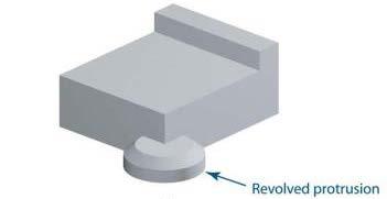
13 SolidWorks: Special Feature Extrusions Extrusions can continue to be added and the resulting protrusion will be joined to the original base If a profile overlaps the original geometry then the two extrusions will merge to create one part
: Edit Feature Edit Sketch Suppress Feature Roll Back Hide Zoom to Feature Normal View to Feature Change appearance")
14 SolidWorks: Editing Features To edit any feature right click on the feature in the model tree The dialogue window allows you to (from left to right, top to bottom): Edit Feature Edit Sketch Suppress Feature Roll Back Hide Zoom to Feature Normal View to Feature Change appearance (color)
15 Extrusion Wrap Up Extrusions Positive Extrusion stretch a 2D profile to 3D Negative Extrusion remove material from a 3D model (cut) Geometries merge Loops have to be CLOSED Homework Assignment SW02-OUT: Create shape shown using positive and negative extrusions. Shape is important, dimensions are not. Print off Isometric with Name, Seat Number, and Instructor. Shape in text Problem 6.4 (f)

16 In-Class Activity Design a camera with positive and negative extrusions. Be creative and feel free to create something original.
17 Revolve ENGR 1182 SolidWorks 02
18 Revolving 2D Profile Extents Full Rotation Degree Axis of Rotation: Attached Closed Solid Separated Solid with Hole

19 Revolve Vs. Extrude Revolve Complements Extrusion Some Objects Difficult to Extrude i.e. Cones, wheels How would you create this object with extrude?


20 Positive Revolves Negative Revolves
21 Acceptable Profiles

22 SolidWorks: Revolution Axis Options in the Line tool can be chosen to create a construction line that will be used as a revolution axis

23 How Could We Create This?
24 SolidWorks: Closed Profile Example of a closed profile aligned with the center axis (created by using a construction line) SolidWorks preview allows the designer to select the correct options

25 How Could We Create This?
 This example shows how to create a hollow revolve.")
26 SolidWorks: Hollow Profile Example of a closed profile separated from the center axis (created by using a construction line) This example shows how to create a hollow revolve. This is helpful in the creation of wheels, etc.
27 Revolves Wrap Up Positive Revolve Make a 3D object Negative Revolve Remove material from a 3D object Attached Rotation Will produce a closed object Homework Assignment SW02-OUT: Create the following shape. Focus on shape and proportionality, not dimensions. Separated Rotation Will produce an object with a hole Use construction lines for axes Ensure validity of profile (entire sketch is on one side of revolution axis)

28 In-Class Activity Draw a wheel using a closed 2D profile similar to what is shown from Problem 6.4 (n)

29 Important Takeaways 3D shapes can be created from 2D sketches using the extrusion and revolve features. Negative extrusions and revolves are used to subtract material for a specified length. Sketching on surfaces after creating the first extrusion is done by clicking the sketch button and selecting the 2D surface desired.

30 What s Next? Due Next Class: SW02 Out-of-Class HW Before next class, you will read about geometric and dimensional constraint based modeling. Geometric constraints constrain geometry based on normal orientations or relative to other parts of geometry. Dimensional constraints are numerical values that constrain the size and location of geometry. Take SolidWorks 3 Quiz on readings
Parametric Modeling Design and Modeling 2011 Project Lead The Way, Inc.
 Parametric Modeling Design and Modeling 2011 Project Lead The Way, Inc. 3D Modeling Steps - Sketch Step 1 Sketch Geometry Sketch Geometry Line Sketch Tool 3D Modeling Steps - Constrain Step 1 Sketch Geometry
Feature-Based Modeling and Optional Advanced Modeling. ENGR 1182 SolidWorks 05
 Feature-Based Modeling and Optional Advanced Modeling ENGR 1182 SolidWorks 05 Today s Objectives Feature-Based Modeling (comprised of 2 sections as shown below) 1. Breaking it down into features Creating
3D Design with 123D Design
 3D Design with 123D Design Introduction: 3D Design involves thinking and creating in 3 dimensions. x, y and z axis Working with 123D Design 123D Design is a 3D design software package from Autodesk. A
Constraint Based Modeling Geometric and Dimensional. ENGR 1182 SolidWorks 03
 Constraint Based Modeling Geometric and Dimensional ENGR 1182 SolidWorks 03 Today s Objectives Using two different type of constraints in SolidWorks: Geometric Dimensional SW03 In-Class Activity List Geometric
SOLIDWORKS: Lesson III Patterns & Mirrors. UCF Engineering
 SOLIDWORKS: Lesson III Patterns & Mirrors UCF Engineering Solidworks Review Last lesson we discussed several more features that can be added to models in order to increase their complexity. We are now
Solid Modeling: Part 1
 Solid Modeling: Part 1 Basics of Revolving, Extruding, and Boolean Operations Revolving Exercise: Stepped Shaft Start AutoCAD and use the solid.dwt template file to create a new drawing. Create the top
Assembly Modeling Constraints. ENGR 1182 SolidWorks 05
 Assembly Modeling Constraints ENGR 1182 SolidWorks 05 Today s Objectives Creating assemblies by constraining 3D parts together Movement and Location dictated by Constraints SW05 Activity SW05 Application
Chapter 10. Creating 3D Objects Delmar, Cengage Learning
 Chapter 10 Creating 3D Objects 2011 Delmar, Cengage Learning Objectives Extrude objects Revolve objects Manipulate surface shading and lighting Map artwork to 3D objects Extrude Objects Extrude & Bevel
3D Modeling. Visualization Chapter 4. Exercises
 Three-dimensional (3D) modeling software is becoming more prevalent in the world of engineering design, thanks to faster computers and better software. Two-dimensional (2D) multiview drawings made using
Solid Modeling SolidWorks Layout. ENGR 1182 SolidWorks 01
 Solid Modeling SolidWorks Layout ENGR 1182 SolidWorks 01 Solid Modeling In The Real World Mechanical and Aerospace engineers need solid models of jet engine components and assemblies to do analysis on
COMPUTER AIDED ARCHITECTURAL GRAPHICS FFD 201/Fall 2013 HAND OUT 1 : INTRODUCTION TO 3D
 COMPUTER AIDED ARCHITECTURAL GRAPHICS FFD 201/Fall 2013 INSTRUCTORS E-MAIL ADDRESS OFFICE HOURS Özgür Genca ozgurgenca@gmail.com part time Tuba Doğu tubadogu@gmail.com part time Şebnem Yanç Demirkan sebnem.demirkan@gmail.com
MOLD DESIGN. Presented by: Nakul Singh, Tim Ralph, Jamie Curtis and Tim Winsor
 MOLD DESIGN Presented by: Nakul Singh, Tim Ralph, Jamie Curtis and Tim Winsor Mold Design Three main components: (a) Core This duplicates the inner surface of the model. It is larger than the finished
Nose Cone. Chapter 4. Rocket 3D Print. A. Revolve. Step 1. Click File Menu > New, click Part and OK. SOLIDWORKS 16 Nose Cone ROCKET 3D PRINT Page 4-1
 Chapter 4 Rocket 3D Print Nose Cone A. Revolve. Step 1. Click File Menu > New, click Part and OK. Step 2. Click Front Plane in the Feature Manager and click Sketch on the content toolbar, Fig. 1. Step
SolidWorks 2013 and Engineering Graphics
 SolidWorks 2013 and Engineering Graphics An Integrated Approach Randy H. Shih SDC PUBLICATIONS Schroff Development Corporation Better Textbooks. Lower Prices. www.sdcpublications.com Visit the following
Input CAD Solid Model Assemblies - Split into separate Part Files. DXF, IGES WMF, EMF STL, VDA, Rhino Parasolid, ACIS
 General NC File Output List NC Code Post Processor Selection Printer/Plotter Output Insert Existing Drawing File Input NC Code as Geometry or Tool Paths Input Raster Image Files Report Creator and Designer
3 AXIS STANDARD CAD. BobCAD-CAM Version 28 Training Workbook 3 Axis Standard CAD
 3 AXIS STANDARD CAD This tutorial explains how to create the CAD model for the Mill 3 Axis Standard demonstration file. The design process includes using the Shape Library and other wireframe functions
Inventor 201. Work Planes, Features & Constraints: Advanced part features and constraints
 Work Planes, Features & Constraints: 1. Select the Work Plane feature tool, move the cursor to the rim of the base so that inside and outside edges are highlighted and click once on the bottom rim of the
Introduction to ANSYS DesignModeler
 Lecture 5 Modeling 14. 5 Release Introduction to ANSYS DesignModeler 2012 ANSYS, Inc. November 20, 2012 1 Release 14.5 Preprocessing Workflow Geometry Creation OR Geometry Import Geometry Operations Meshing
Memo Block. This lesson includes the commands Sketch, Extruded Boss/Base, Extruded Cut, Shell, Polygon and Fillet.
 Commands Used New Part This lesson includes the commands Sketch, Extruded Boss/Base, Extruded Cut, Shell, Polygon and Fillet. Click File, New on the standard toolbar. Select Part from the New SolidWorks
Autodesk Fusion 360: Model. Overview. Modeling techniques in Fusion 360
 Overview Modeling techniques in Fusion 360 Modeling in Fusion 360 is quite a different experience from how you would model in conventional history-based CAD software. Some users have expressed that it
CATIA Surface Design
 CATIA V5 Training Exercises CATIA Surface Design Version 5 Release 19 September 2008 EDU_CAT_EN_GS1_FX_V5R19 Table of Contents (1/2) Creating Wireframe Geometry: Recap Exercises 4 Creating Wireframe Geometry:
TUTORIAL 2. OBJECTIVE: Use SolidWorks/COSMOS to model and analyze a cattle gate bracket that is subjected to a force of 100,000 lbs.
 TUTORIAL 2 OBJECTIVE: Use SolidWorks/COSMOS to model and analyze a cattle gate bracket that is subjected to a force of 100,000 lbs. GETTING STARTED: 1. Open the SolidWorks program. 2. Open a new part file.
6. CAD SOFTWARE. CAD is a really useful tool for every engineer, and especially for all the designers.
 6. CAD SOFTWARE CAD is a really useful tool for every engineer, and especially for all the designers. Not only because it makes drawing easier, but because it presents the advantage that if any detail
TRAINING GUIDE SOLIDS-LESSON-3
 TRAINING GUIDE SOLIDS-LESSON-3 Mastercam Training Guide Objectives You will generate the solid model from the existing 2-dimensional geometry. This Lesson covers the following topics: Open an existing
Structural & Thermal Analysis using the ANSYS Workbench Release 11.0 Environment. Kent L. Lawrence
 ANSYS Workbench Tutorial Structural & Thermal Analysis using the ANSYS Workbench Release 11.0 Environment Kent L. Lawrence Mechanical and Aerospace Engineering University of Texas at Arlington SDC PUBLICATIONS
CATIA V5 Parametric Surface Modeling
 CATIA V5 Parametric Surface Modeling Version 5 Release 16 A- 1 Toolbars in A B A. Wireframe: Create 3D curves / lines/ points/ plane B. Surfaces: Create surfaces C. Operations: Join surfaces, Split & Trim
SOLIDWORKS 2016 and Engineering Graphics
 SOLIDWORKS 2016 and Engineering Graphics An Integrated Approach Randy H. Shih SDC PUBLICATIONS Better Textbooks. Lower Prices. www.sdcpublications.com Powered by TCPDF (www.tcpdf.org) Visit the following
Lesson 1 Parametric Modeling Fundamentals
 1-1 Lesson 1 Parametric Modeling Fundamentals Create Simple Parametric Models. Understand the Basic Parametric Modeling Process. Create and Profile Rough Sketches. Understand the "Shape before size" approach.
Solid Bodies and Disjointed Bodies
 Solid Bodies and Disjointed Bodies Generally speaking when modelling in Solid Works each Part file will contain single solid object. As you are modelling, each feature is merged or joined to the previous
Battery Holder. Chapter 9. Boat. A. Front Extrude. Step 1. Click File Menu > New, click Part and OK. SolidWorks 10 BATTERY HOLDER AA BOAT Page 9-1
 Chapter 9 Boat Battery Holder A. Front Extrude. Step 1. Click File Menu > New, click Part and OK. AA Step 2. Click Front (plane) in the Feature Manager and click Sketch from the Content toolbar, Fig. 1.
CO2 Rail Car. Wheel Rear Px. on the Command Manager toolbar.
 Chapter 6 CO2 Rail Car Wheel Rear Px A. Sketch Construction Lines. Step 1. Click File Menu > New, click Part Metric and OK. Step 2. Click Front (plane) in the Feature Manager (left panel), Fig. 1. Step
Chapter 2 Parametric Modeling Fundamentals
 2-1 Chapter 2 Parametric Modeling Fundamentals Create Simple Extruded Solid Models Understand the Basic Parametric Modeling Procedure Create 2-D Sketches Understand the Shape before Size Approach Use the
Autodesk Inventor - Basics Tutorial Exercise 1
 Autodesk Inventor - Basics Tutorial Exercise 1 Launch Inventor Professional 2015 1. Start a New part. Depending on how Inventor was installed, using this icon may get you an Inch or Metric file. To be
Wheel GT-F. Chapter 5. CO2 Shell Car. A. Sketch. Step 1. Click File Menu > New, click Part Metric and OK.
 Chapter 5 CO2 Shell Car Wheel GT-F A. Sketch. Step 1. Click File Menu > New, click Part Metric and OK. Step 2. Click Front Plane in the Feature Manager and click Sketch on the context toolbar, Fig. 1.
Structural & Thermal Analysis Using the ANSYS Workbench Release 12.1 Environment
 ANSYS Workbench Tutorial Structural & Thermal Analysis Using the ANSYS Workbench Release 12.1 Environment Kent L. Lawrence Mechanical and Aerospace Engineering University of Texas at Arlington SDC PUBLICATIONS
Autodesk Inventor Design Exercise 2: F1 Team Challenge Car Developed by Tim Varner Synergis Technologies
 Autodesk Inventor Design Exercise 2: F1 Team Challenge Car Developed by Tim Varner Synergis Technologies Tim Varner - 2004 The Inventor User Interface Command Panel Lists the commands that are currently
Character Modeling IAT 343 Lab 6. Lanz Singbeil
 Character Modeling IAT 343 Lab 6 Modeling Using Reference Sketches Start by creating a character sketch in a T-Pose (arms outstretched) Separate the sketch into 2 images with the same pixel height. Make
Solid Bodies and Disjointed bodies
 Solid Bodies and Disjointed bodies Generally speaking when modelling in Solid Works each Part file will contain single solid object. As you are modelling, each feature is merged or joined to the previous
Propeller. Chapter 13. Airplane. A. Base for Blade. Step 1. Click File Menu > New, click Part and OK.
 Chapter 13 Airplane Propeller A. Base for Blade. Step 1. Click File Menu > New, click Part and OK. Step 2. Click Top Plane in the Feature Manager and click Sketch toolbar, Fig. 1. from the Content Step
3D AUTOCAD. The view we ve been working in is a top or plan view. From this view even a 3D drawing will appear 2D.
 3D AUTOCAD Thus far, we ve looked at tools and operations in 2D with work completed on only the X- and Y- axes. The axes symbol has been present on our screen but we haven t had much use for it. The view
Version 2011 R1 - Router
 GENERAL NC File Output List NC Code Post Processor Selection Printer/Plotter Output Insert Existing Drawing File Input NC Code as Geometry or Tool Paths Input Raster Image Files Convert Raster to Vector
Module 2 Review. Assemblies and Rendering. Why Use Assemblies. Assemblies - Key Concepts. Sketch Planes Sketched Features.
 Module 2 Review Assemblies and Rendering EF 101 Modules 3.1, 3.2 Sketch Planes Sketched Features Extrude, Revolve Placed Features Hole, Fillet, Chamfer, Shell, Rect. Pattern Drawing Views Base, Ortho,
3D printing Workshop Breakdown
 3D printing Workshop Breakdown Opening Lecture/Remarks (20-30 Minutes) -Introduction to 3D modeling software Overview of what 3D modeling software is Introduction to 123D Design Introduction to 123D Design
Exercise Guide. Published: August MecSoft Corpotation
 VisualCAD Exercise Guide Published: August 2018 MecSoft Corpotation Copyright 1998-2018 VisualCAD 2018 Exercise Guide by Mecsoft Corporation User Notes: Contents 2 Table of Contents About this Guide 4
Autodesk Inventor 2019 and Engineering Graphics
 Autodesk Inventor 2019 and Engineering Graphics An Integrated Approach Randy H. Shih SDC PUBLICATIONS Better Textbooks. Lower Prices. www.sdcpublications.com Powered by TCPDF (www.tcpdf.org) Visit the
Modeling a Gear Standard Tools, Surface Tools Solid Tool View, Trackball, Show-Hide Snaps Window 1-1
 Modeling a Gear This tutorial describes how to create a toothed gear. It combines using wireframe, solid, and surface modeling together to create a part. The model was created in standard units. To begin,
Module 1: Basics of Solids Modeling with SolidWorks
 Module 1: Basics of Solids Modeling with SolidWorks Introduction SolidWorks is the state of the art in computer-aided design (CAD). SolidWorks represents an object in a virtual environment just as it exists
Mastercam X9 for SOLIDWORKS
 Chapter 21 CO2 Shell Car Mastercam X9 for SOLIDWORKS A. Enable Mastercam for SOLIDWORKS. Step 1. If necessary, turn on Mastercam for SOLIDWORKS, click the flyout of Options on the Standard toolbar and
Section 7.2 Volume: The Disk Method
 Section 7. Volume: The Disk Method White Board Challenge Find the volume of the following cylinder: No Calculator 6 ft 1 ft V 3 1 108 339.9 ft 3 White Board Challenge Calculate the volume V of the solid
Lesson 2 Constructive Solid Geometry Concept. Parametric Modeling with I-DEAS 2-1
 Lesson 2 Constructive Solid Geometry Concept Parametric Modeling with I-DEAS 2-1 2-2 Parametric Modeling with I-DEAS Introduction In the 1980s, one of the main advancements in Solid Modeling was the development
Parametric Modeling with SolidWorks
 Parametric Modeling with SolidWorks 2012 LEGO MINDSTORMS NXT Assembly Project Included Randy H. Shih Paul J. Schilling SDC PUBLICATIONS Schroff Development Corporation Better Textbooks. Lower Prices. www.sdcpublications.com
Delta Dart. Propeller. in the Feature Manager and click Sketch from the Content toolbar, Fig. 1. on the Sketch toolbar.
 Chapter 8 Delta Dart Propeller A. Base for Blade. Step 1. Click File Menu > New, click Part Metric and OK. Step 2. Click Top Plane in the Feature Manager and click Sketch from the Content toolbar, Fig.
Panel. Chapter 16. Solar Car. A. Sketch. Step 1. Click File Menu > New, click Part and OK. B. Save as "PANEL". Step 1. Click File Menu > Save As.
 Chapter 16 Solar Car Panel A. Sketch. Step 1. Click File Menu > New, click Part and OK. Step 2. Click Top Plane in the Feature Manager and click Sketch from the Content toolbar, Fig. 1. Step 3. Click Center
Assembly Modeling Constraints
 Assembly Modeling Constraints College of Engineering Engineering Education Innovation Center Rev: 20130715 AJP Assembly Modeling Constraints 1 Assemblies Assemblies are collections of 3D parts that form
F1 Car. Wheel. in the Feature Manager and click Sketch on the Context toolbar, Fig. 1. (S) on the
 on the") Chapter 3 F1 Car Wheel A. Sketch Lines. Step 1. Click File Menu > New, click Part Metric and OK. Step 2. Click Front Plane in the Feature Manager and click Sketch on the Context toolbar, Fig. 1. Step 3.
Chapter 3 F1 Car Wheel A. Sketch Lines. Step 1. Click File Menu > New, click Part Metric and OK. Step 2. Click Front Plane in the Feature Manager and click Sketch on the Context toolbar, Fig. 1. Step 3.
Simple Machines. Wheel. in the Feature Manager and click Sketch. on the Command Manager toolbar.
 Chapter 3 Simple Machines Wheel A. Wheel. Step 1. Click File Menu > New, click Part and OK. Step 2. Click Right Plane from the Content toolbar, Fig. 1. in the Feature Manager and click Sketch Step 3. Click
Name. Center axis. Introduction to Conic Sections
 Name Introduction to Conic Sections Center axis This introduction to conic sections is going to focus on what they some of the skills needed to work with their equations and graphs. year, we will only
Chair. Top Rail. on the Standard Views toolbar. (Ctrl-7) on the Weldments toolbar. at bottom left corner of display to deter- mine sketch plane.
 on the Weldments toolbar. at bottom left corner of display to deter- mine sketch plane.") Chapter 7 A. 3D Sketch. Step 1. If necessary, open your CHAIR file. Chair Top Rail Step 2. Click Isometric on the Standard Views toolbar. (Ctrl-7) Step 3. Zoom in around top of back leg, Fig. 1. To zoom,
Chapter 7 A. 3D Sketch. Step 1. If necessary, open your CHAIR file. Chair Top Rail Step 2. Click Isometric on the Standard Views toolbar. (Ctrl-7) Step 3. Zoom in around top of back leg, Fig. 1. To zoom,
Solid Problem Ten. In this chapter, you will learn the following to World Class standards:
 C h a p t e r 11 Solid Problem Ten In this chapter, you will learn the following to World Class standards: 1. Sketch of Solid Problem Ten 2. Starting a 3D Part Drawing 3. Modifying How the UCS Icon is
Lesson 17 Shell, Reorder, and Insert Mode
 Lesson 17 Shell, Reorder, and Insert Mode Figure 17.1 Oil Sink OBJECTIVES Master the use of the Shell Tool Reorder features Insert a feature at a specific point in the design order Create a Hole Pattern
FOLLOWING ALONG THE PATH
 FOLLOWING ALONG THE PATH 3D MODULE 18 OBJECTIVES At the completion of the Module you should be able to: Create a solid model by extruding a profile along a predefined pathway. Use the Press/Pull command
SOLIDWORKS Parametric Modeling with SDC. Covers material found on the CSWA exam. Randy H. Shih Paul J. Schilling
 Parametric Modeling with SOLIDWORKS 2015 Covers material found on the CSWA exam Randy H. Shih Paul J. Schilling SDC PUBLICATIONS Better Textbooks. Lower Prices. www.sdcpublications.com Powered by TCPDF
User Guide. for. JewelCAD Professional Version 2.0
 User Guide Page 1 of 121 User Guide for JewelCAD Professional Version 2.0-1 - User Guide Page 2 of 121 Table of Content 1. Introduction... 7 1.1. Purpose of this document... 7 2. Launch JewelCAD Professional
3D Modeling and Design Glossary - Beginner
 3D Modeling and Design Glossary - Beginner Align: to place or arrange (things) in a straight line. To use the Align tool, select at least two objects by Shift left-clicking on them or by dragging a box
Introduction to Solid Modeling Parametric Modeling. Mechanical Engineering Dept.
 Introduction to Solid Modeling Parametric Modeling 1 Why draw 3D Models? 3D models are easier to interpret. Simulation under real-life conditions. Less expensive than building a physical model. 3D models
Introduction to AutoCAD 2010
 Page 1 Introduction to AutoCAD 2010 Alf Yarwood Chapter 18 Exercise 1 1. Open AutoCAD 2010 with a double-click on its shortcut icon in the Windows desktop. 2. Open the template acadiso3d.dwt. 3. Make new
Body. Chapter 2. CO2 Rail Car E. A. Save as "BODY RAIL E". Step 1. Open your BLANK file.
 Chapter 2 A. Save as "BODY RAIL E". Step 1. Open your BLANK file. Step 2. Click File Menu > Save As. Step 3. Key-in BODY RAIL E for the filename and press ENTER. CO2 Rail Car E Body B. Appearance. Step
Chapter 2 Parametric Modeling Fundamentals
 2-1 Chapter 2 Parametric Modeling Fundamentals Create Simple Extruded Solid Models Understand the Basic Parametric Modeling Procedure Create 2-D Sketches Understand the "Shape before Size" Approach Use
Module 5: Creating Sheet Metal Transition Piece Between a Square Tube and a Rectangular Tube with Triangulation
 1 Module 5: Creating Sheet Metal Transition Piece Between a Square Tube and a Rectangular Tube with Triangulation In Module 5, we will learn how to create a 3D folded model of a sheet metal transition
SolidWorks 2015 User Interface
 SolidWorks 2015 User Interface SolidWorks a Dassault Systèmes Product Starting SolidWorks 1) On the desktop, double-click or from the start menu select: All Programs SOLIDWORKS 2015 SOLIDWORKS 2015. 2)
3. Preprocessing of ABAQUS/CAE
 3.1 Create new model database 3. Preprocessing of ABAQUS/CAE A finite element analysis in ABAQUS/CAE starts from create new model database in the toolbar. Then save it with a name user defined. To build
Module 4B: Creating Sheet Metal Parts Enclosing The 3D Space of Right and Oblique Pyramids With The Work Surface of Derived Parts
 Inventor (5) Module 4B: 4B- 1 Module 4B: Creating Sheet Metal Parts Enclosing The 3D Space of Right and Oblique Pyramids With The Work Surface of Derived Parts In Module 4B, we will learn how to create
3D ModelingChapter1: Chapter. Objectives
 Chapter 1 3D ModelingChapter1: The lessons covered in this chapter familiarize you with 3D modeling and how you view your designs as you create them. You also learn the coordinate system and how you can
Parametric Modeling. With. Autodesk Inventor. Randy H. Shih. Oregon Institute of Technology SDC PUBLICATIONS
 Parametric Modeling With Autodesk Inventor R10 Randy H. Shih Oregon Institute of Technology SDC PUBLICATIONS Schroff Development Corporation www.schroff.com www.schroff-europe.com 2-1 Chapter 2 Parametric
How to Create a Fountain Pen
 How to Create a Fountain Pen Lesson 4 How to Create a Fountain Pen This lesson will guide you in building a fountain pen. You will use the following tools: NURBS curves. Extrusion. Mirror. Trim. Blend
CHAPTER 6 THE SUITES VECTOR DRAWING SUITE
 CHAPTER 6 THE SUITES There are two additional tool bar suites for Project Designer sold separately as add-on modules. These are the Vector Drawing Suite, and the Pattern Modeling Suite. This section will
Generative Shape Design
 Generative Shape Design Copyright DASSAULT SYSTEMES 2002 1 Exercise 60 min. The Knob In this exercise you will have the opportunity to model an appliance Knob starting from an empty model. You will create
SOLIDWORKS: Lesson 1 - Basics and Modeling. UCF Engineering
 SOLIDWORKS: Lesson 1 - Basics and Modeling Fundamentals UCF Engineering SolidWorks SolidWorks is a 3D solid modeling package which allows users to develop full solid models in a simulated environment for
Parametric Modeling with SOLIDWORKS 2017
 Parametric Modeling with SOLIDWORKS 2017 NEW Contains a new chapter on 3D printing Covers material found on the CSWA exam Randy H. Shih Paul J. Schilling SDC PUBLICATIONS Better Textbooks. Lower Prices.
REVIT ARCHITECTURE 2016
 Page 1 of 6 REVIT ARCHITECTURE 2016 Revit Architecture 2016: CREATE A CHAMFERED COLUMN COMPONENT About creating a chamfered column family typical to the Victorian cottage style. Add the column to your
Learning. Modeling, Assembly and Analysis SOLIDWORKS Randy H. Shih SDC. Better Textbooks. Lower Prices.
 Learning SOLIDWORKS 2016 Modeling, Assembly and Analysis Randy H. Shih SDC PUBLICATIONS Better Textbooks. Lower Prices. www.sdcpublications.com Powered by TCPDF (www.tcpdf.org) Visit the following websites
Skateboard. Hanger. in the Feature Manager and click Sketch on the Context toolbar, Fig. 1. Fig. 2
 Chapter 3 Skateboard Hanger A. Sketch1 Lines. Step 1. Click File Menu > New, click Part Metric and OK. Step 2. Click Right Plane in the Feature Manager and click Sketch on the Context toolbar, Fig. 1.
Getting started with Solid Edge with Synchronous Technology
 Getting started with Solid Edge with Synchronous Technology Publication Number MU29000-ENG-1000 Proprietary and Restricted Rights Notice This software and related documentation are proprietary to Siemens
F-1 Car. Blank. in the Feature Manager and click Sketch from the Content toolbar, Fig. 3. Origin. on the Features toolbar.
 Chapter 1 A. New Metric Part. Step 1. Click File Menu > New. F-1 Car Blank Step 2. Click Part Metric from the list of templates and click OK, Fig. 1. If you are not using SOLIDWORKS templates (you should
Terminal. Chapter 16. E-Car. A. Component from Design Library. SOLIDWORKS 17 Terminal E-CAR Page 16-1
 Chapter 16 E-Car Terminal A. Component from Design Library. Step 1. Click the Design Library tab in the Task Pane (right side of graphics area), Fig. 1. Step 2. Expand routing and click electrical folder
CO2 Shell Car. Axle Retainer. in the Feature Manager and click Sketch from the Content toolbar, Fig. 1. (L) on the Sketch toolbar. Fig.
 on the Sketch toolbar. Fig.") Chapter 17 CO2 Shell Car Axle Retainer A. Sketch. Step 1. Click File Menu > New, click Part Metric and OK. Step 2. Click Top Plane in the Feature Manager and click Sketch from the Content toolbar, Fig.
Chapter 17 CO2 Shell Car Axle Retainer A. Sketch. Step 1. Click File Menu > New, click Part Metric and OK. Step 2. Click Top Plane in the Feature Manager and click Sketch from the Content toolbar, Fig.
SolidWorks Modeler Getting Started Guide Desktop EDA
 SolidWorks Modeler Getting Started Guide SolidWorks Modeler Getting Started Guide All rights reserved. No parts of this work may be reproduced in any form or by any means - graphic, electronic, or mechanical,
Solar Car. Chassis. in the Feature Manager and click Sketch from the Content toolbar, Fig. 2. Origin. on the Command Manager toolbar. Fig.
 Chapter 1 A. New Part. Step 1. Click File Menu > New. Solar Car Chassis Step 2. Click Part from the list and click OK, Fig. 1. B. Sketch Chassis. Step 1. Click Right Plane in the Feature Manager and click
An Introduction to Autodesk Inventor 2010 and AutoCAD Randy H. Shih SDC PUBLICATIONS. Schroff Development Corporation
 An Introduction to Autodesk Inventor 2010 and AutoCAD 2010 Randy H. Shih SDC PUBLICATIONS Schroff Development Corporation www.schroff.com 2-1 Chapter 2 Parametric Modeling Fundamentals Create Simple Extruded
Doctor Walt s Solid Edge Version 19 Workbook 137
 Still using the SMART DIMENSION Tool, click on the left vertical edge of the sketch. Move the cursor to the left and click to set the text position. Type 1.5 for the value and hit the ENTER Key. Next,
Drawing. Chapter 10. Airplane. A. Insert Right View. Step 1. Click File Menu > New, click Drawing and OK.
 Chapter 10 Airplane Drawing A. Insert Right View. Step 1. Click File Menu > New, click Drawing and OK. Step 2. Click Model View on the View Layout toolbar. Step 3. Click Browse in the Property Manager.
Module 4A: Creating the 3D Model of Right and Oblique Pyramids
 Inventor (5) Module 4A: 4A- 1 Module 4A: Creating the 3D Model of Right and Oblique Pyramids In Module 4A, we will learn how to create 3D solid models of right-axis and oblique-axis pyramid (regular or
Module 8A: Creating a Sheet Metal Part & Flat Pattern Wrapping the 3D Space of a Polyhedron
 1 Module 8A: Creating a Sheet Metal Part & Flat Pattern Wrapping the 3D Space of a Polyhedron In this Module, we will learn how to create a sheet metal part wrapping a polyhedron based on an octagonal
Google SketchUp. and SketchUp Pro 7. The book you need to succeed! CD-ROM Included! Kelly L. Murdock. Master SketchUp Pro 7 s tools and features
 CD-ROM Included! Free version of Google SketchUp 7 Trial version of Google SketchUp Pro 7 Chapter example files from the book Kelly L. Murdock Google SketchUp and SketchUp Pro 7 Master SketchUp Pro 7 s
Introduction to Solid Modeling
 Introduction to Solid Modeling Parametric Modeling 1 Why draw 3D Models? 3D models are easier to interpret. 3D models can be used to perform engineering analysis, finite element analysis (stress, deflection,
34 people attended this meeting.
 NEWSUG Meeting Minutes February 8, 2011, 5:00 p.m. Fox Valley Technical College, Appleton, Wisconsin While this report generally covers the meeting events, those events have been arranged into a logical
Solidworks 2006 Surface-modeling
 Solidworks 2006 Surface-modeling (Tutorial 2-Mouse) Surface-modeling Solid-modeling A- 1 Assembly Design Design with a Master Model Surface-modeling Tutorial 2A Import 2D outline drawing into Solidworks2006
Chapter 4 Feature Design Tree
 4-1 Chapter 4 Feature Design Tree Understand Feature Interactions Use the FeatureManager Design Tree Modify and Update Feature Dimensions Perform History-Based Part Modifications Change the Names of Created
Additional Surface Tools
 Additional Surface Tools Several additional surface tools, techniques, and related functions are available. This supplement provides a brief introduction to those functions. Panel Part Features Replace
Parametric Modeling with. Autodesk Fusion 360. First Edition. Randy H. Shih SDC. Better Textbooks. Lower Prices.
 Parametric Modeling with Autodesk Fusion 360 First Edition Randy H. Shih SDC PUBLICATIONS Better Textbooks. Lower Prices. www.sdcpublications.com Powered by TCPDF (www.tcpdf.org) Visit the following websites