Image Transfer Methods. Satya Prakash Mallick Jan 28 th, 2003
|
|
|
- Kathlyn Stanley
- 5 years ago
- Views:
Transcription
1 Image Transfer Methods Satya Prakash Mallick Jan 28 th, 2003


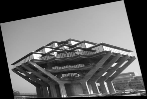
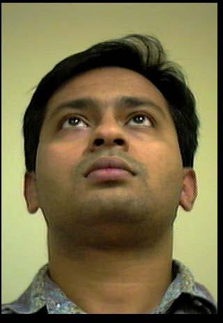
2 Objective Given two or more images of the same scene, the objective is to synthesize a novel view of the scene from a view point where there is no camera. Left Image Synthesized Images Right Image
3 Approaches 1. Traditional Approach: Generate a 3D representation of the scene Render the scene, given a view point Problems: Generating 3D from 2D images is generally very noisy. Generating 3D from 2D can be computationally prohibitive for real-time applications.
4 Approaches Light Field Rendering/ Lumigraph It s an elegant method in which one doesn t need to compute 3D information Problems: Calculation of the light field requires additional machinery. Calculation of light field can be very memory intensive.
5 Approaches Image Transfer Methods: Only 2D image operations are used to generate the novel view. 3D is never calculated explicitly. Its extremely fast. ( The OpenCV implementation of Stiez s algorithm works in real time!). Problems: Usually these methods cannot generate views from any arbitrary view point. There is a limitation on the quality of rendering that can be achieved. Ex. Its difficult to render using a different lighting condition.
6 Papers ( In Chronological Order) E. Chen, L. Williams,View Interpolation for Image Synthesis, SIGGRAPH 1993 S. Seitz, C. Dyer, View Morphing SIGGRAPH, pp , S Avidan, A. Shashua Novel View Synthesis by Cascading Trilinear Tensors IEEE Transactions on visualization and computer graphics, Vol 4, No. 4, October-November Y. Genc, J. Ponce. Image-Based Rendering Using Parameterized Image Varieties. International Journal of Computer Vision, Vol. 41, No. 3, pp , 2001.
7 What do these paper represent? 1993: Image based rendering was still at it s infancy. The first paper DOESNOT represent an image transfer method 1996: One of the first image transfer methods which used two images. However, only in-between views could be generated. 1998: An image transfer method using 2 cameras was introduced which use trilinear tensor to overcome the limitation of view generation along a line only. 2001: A new image transfer method is introduced. It relies on minimum parameterization of image space.
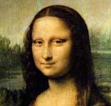
8 Theoretical background Image Morphing: (Term coined by T. Beier, 1992) [0,1], ) ( )C (1 ), W ( ) ( C ) (1 ), W ( Correspondence Maps : C : C : Input images, = + = s I p I p sp p s s p p s p s s p I I I I I I The warped image is an average of the pixel intensities obtained using forward warping and backward warping.

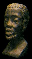
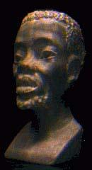
9 Physical Validity of Morphing If two images of the same object are morphed, the resulting image may not represent the same image geometrically.
10 Z - Buffering 1. Clear the color buffer to the background color 2. Initialize all xy coordinates in the Z buffer to one 3. For each fragment of each surface, compare depth values to those already stored in the Z buffer - Calculate the distance from the projection plane for each xy position on the surface - If the distance is less than the value currently stored in the Z buffer: Set the corresponding position in the color buffer to the color of the fragment Set the value in the Z buffer to the distance to that object - Otherwise: Leave the color and Z buffers unchanged
11 View Interpolation Given: Many images of the same scene. Their range data ( 3D is already given!). Camera Transformation Objective: To have a smooth navigation system through the scene ( Virtual Walkthrough ). Note: This is NOT an image transfer method.
 and the relative orientation of the cameras is also known, a 4x4 transformation relates the points in one image to other.")
12 View Interpolation The algorithm: 1. Pixel Correspondence Since Pixel s screen coordinates are known (x,y,z) and the relative orientation of the cameras is also known, a 4x4 transformation relates the points in one image to other. The above transformation can be stored as a offset vector for each pixel. This is called morph map. 2. Interpolating Correspondences: Offset vectors are interpolated linearly and the pixels in the source image are moved by the interpolated vector to the destination image.

13 View Interpolation The algorithm ( Contd. ) 2. Interpolating Correspondences: The interpolation is an approximation of pixel coordinate transformation by a perspective viewing matrix. 3. Composting Images: Visibility Resolution: Z-buffering can be used. A view independent visible priority can be used. Holes: Can be filled using interpolation of color from neighboring pixels. 4. Block Compression: Neighboring pixel move together. Hence morphing map can be defined for blocks of images rather than pixels.
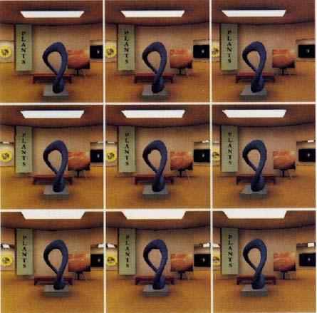
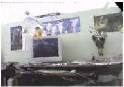
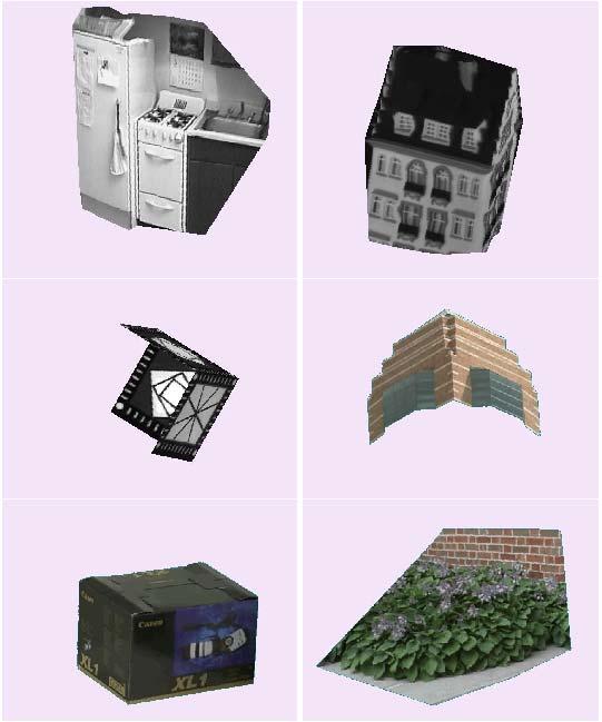
14 Results
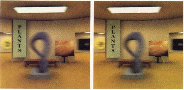
15 Results
16 Drawbacks For real scenes having dense disparity or/and perfect correspondence between pixels is extremely difficult. The underlying assumptions make it suitable only for synthetic data. No wonder, only synthetic results were shown.
17 The Geometry of Multiple Views Epipolar Geometry The Essential Matrix The Fundamental Matrix The Trifocal Tensor
18 Epipolar Geometry Epipolar Plane Epipolar Lines Epipoles Baseline
19 Epipolar Constraint Potential matches for p have to lie on the corresponding epipolar line l. Potential matches for p have to lie on the epipolar line l.
20 Epipolar Constraint: Ideal Case Essential Matrix (Longuet-Higgins, 1981)
21 Properties of the Essential Matrix Ep is the epipolar line associated with p. T E p is the epipolar line associated with p. E e =0 and E e=0. E is singular. T E has two equal non-zero singular values (Huang and Faugeras, 1989).
22 Epipolar Constraint: Real Case Fundamental Matrix (Faugeras and Luong, 1992)
23 Image Rectification


24 An Example Due to Josh Wills
25 Image Rectification To make the epipolar lines parallel to each other and aligned to one of the scanlines, we should send the epipoles to infinity. Rectified image is obtained by a rotation of the original image keeping the optical center fixed. Hence, they are related by a homography.
26 Image Rectification Such a Homography is given by: H = GR, R = a rotation which takes epipole(e) to ( T f,0,1) G= 1 0 1/ f As is easily seen, T T G* ( f,0,1) = ( f,0,0) = point at infinity If the images are related by a fundamental matrix, F = [ e] M, Then the homography which ensures that both images are aligned is given by: H ' = ( I + Hea T ) HM
27 View Morphing Image morphing is shape preserving only in the special case when the images are taken using cameras having parallel optical axes. An additional step called image rectification is introduced. Image interpolation on rectified images produces physically valid in-between images. Rectification is a process of aligning corresponding epipolar lines in the two images along their scanlines.
28 The algorithm Find a few point correspondences in both images. Estimate the fundamental matrix using 8- point algorithm along with RANSAC. Rectify both the images. Find dense correspondence and morph the rectified images Post warp the morphed image. Remove holes ( moirs ).
29 Step By Step

30 Step By Step
31 Surprise!

32 Some Results
33 Novel View Synthesis using Trilinear Tensors What is a Tensor? Any array of numbers: A scalar is a zero dimensional tensor, a vector is a one dimensional tensor, a matrix is a two dimensional tensor and so on. A Trilinear Tensor is a 3x3x3 array. Three views satisfy certain matching constraints represented by a tensor. Given two views in correspondence and a tensor, the corresponding third view can be generated by means of a warping function.
34 Constraint Equation p i s µ j r ρ k T i jk = 0
35 More Hand waiving! Let p, p are known. i jk Then p s µ j Ti is a point that coincides with all lines passing through p. Hence, given images i p, p of a point in two views and a tensor we can find the image of the point in the third view by the reprojection equation given by: i µ jk k p s j Ti p"
36 Basic Tensor Operator Basic Tensor Operator describes how to modify a tensor so as to represent a new set of cameras. Let, [I;0], [A,V],[B,V ] and [C,V ] be the camera matrices associated with the views in question. Let be jk T i the jk tensor between views 1,2,3 and G i be the tensor between views 1,2,4. If the motion parameters between views 3 and 4 are represented by D, then we have a relationship: jk k jk G i = di Ti + Hence, corresponding to different D s, we can have different viewpoints. t k a j i
37 The Algorithm Pre-processing steps: Compute dense correspondence (optical-flow) between the pair of reference images. Construct the trilinear tensor of the two images Extract the rotation matrix of the two images from the trilinear tensor. View Synthesis steps: Accept the rotation and translation of the novel image. Construct the new tensor Reproject the novel image.
38 Results
39 Rendering using PIV Punch Line: The set of all images of a rigid set of m points and n lines observed using a weak perspective camera can be represented by a 2( m n six dimensional variety embedded in R + and can be parameterized by the image coordinates of three reference points ) Note: Loosely speaking, a variety can be thought to be a subspace
40 Basic Ideas Given: a) Images of a rigid scene taken from different view points. These images are called training images. b) A set of point( m in no. ) and line ( n in no. ) correspondences in all training images. c) Coordinates of 3 reference points in all images.
41 The Algorithm The position of m points and the position and orientation of n lines can be used to calculate some parameters which define the scene. Training Image1 Training Image2 Training Image3 Parameters p1, p2,p3..
42 The view point of the image to be synthesized is expressed by the location of the three points in the synthesized image. Training Image1 Training Image2 Training Image3 Synthesized Image The positions of three points in the Synthesized image specifies the viewpoint ( Instead of the normal viewing matrix or R and T)
43 The parameters can then be used to calculate the position and orientation of all m points and n lines in the synthesized image. Parameters p1, p2, p3. position of points which specify the viewpoint + Synthesized Image: We get the position and orientation of lines and points in the synthesized image.
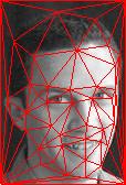
44 Training Image1 Training Image2 Training Image3 Synthesized Image Triangulation based Rendering Complete Synthesized Image
45 Results
But First: Multi-View Projective Geometry
 View Morphing (Seitz & Dyer, SIGGRAPH 96) Virtual Camera Photograph Morphed View View interpolation (ala McMillan) but no depth no camera information Photograph But First: Multi-View Projective Geometry
Lecture 6 Stereo Systems Multi-view geometry
 Lecture 6 Stereo Systems Multi-view geometry Professor Silvio Savarese Computational Vision and Geometry Lab Silvio Savarese Lecture 6-5-Feb-4 Lecture 6 Stereo Systems Multi-view geometry Stereo systems
Lecture 6 Stereo Systems Multi- view geometry Professor Silvio Savarese Computational Vision and Geometry Lab Silvio Savarese Lecture 6-24-Jan-15
 Lecture 6 Stereo Systems Multi- view geometry Professor Silvio Savarese Computational Vision and Geometry Lab Silvio Savarese Lecture 6-24-Jan-15 Lecture 6 Stereo Systems Multi- view geometry Stereo systems
Multiple Views Geometry
 Multiple Views Geometry Subhashis Banerjee Dept. Computer Science and Engineering IIT Delhi email: suban@cse.iitd.ac.in January 2, 28 Epipolar geometry Fundamental geometric relationship between two perspective
Reminder: Lecture 20: The Eight-Point Algorithm. Essential/Fundamental Matrix. E/F Matrix Summary. Computing F. Computing F from Point Matches
 Reminder: Lecture 20: The Eight-Point Algorithm F = -0.00310695-0.0025646 2.96584-0.028094-0.00771621 56.3813 13.1905-29.2007-9999.79 Readings T&V 7.3 and 7.4 Essential/Fundamental Matrix E/F Matrix Summary
Today. Stereo (two view) reconstruction. Multiview geometry. Today. Multiview geometry. Computational Photography
 reconstruction. Multiview geometry. Today. Multiview geometry. Computational Photography") Computational Photography Matthias Zwicker University of Bern Fall 2009 Today From 2D to 3D using multiple views Introduction Geometry of two views Stereo matching Other applications Multiview geometry
Computational Photography Matthias Zwicker University of Bern Fall 2009 Today From 2D to 3D using multiple views Introduction Geometry of two views Stereo matching Other applications Multiview geometry
Epipolar Geometry and Stereo Vision
 Epipolar Geometry and Stereo Vision Computer Vision Jia-Bin Huang, Virginia Tech Many slides from S. Seitz and D. Hoiem Last class: Image Stitching Two images with rotation/zoom but no translation. X x
Lecture 9: Epipolar Geometry
 Lecture 9: Epipolar Geometry Professor Fei Fei Li Stanford Vision Lab 1 What we will learn today? Why is stereo useful? Epipolar constraints Essential and fundamental matrix Estimating F (Problem Set 2
Computer Vision Lecture 17
 Computer Vision Lecture 17 Epipolar Geometry & Stereo Basics 13.01.2015 Bastian Leibe RWTH Aachen http://www.vision.rwth-aachen.de leibe@vision.rwth-aachen.de Announcements Seminar in the summer semester
Computer Vision Lecture 17
 Announcements Computer Vision Lecture 17 Epipolar Geometry & Stereo Basics Seminar in the summer semester Current Topics in Computer Vision and Machine Learning Block seminar, presentations in 1 st week
Lecture 14: Basic Multi-View Geometry
 Lecture 14: Basic Multi-View Geometry Stereo If I needed to find out how far point is away from me, I could use triangulation and two views scene point image plane optical center (Graphic from Khurram
Epipolar Geometry and Stereo Vision
 Epipolar Geometry and Stereo Vision Computer Vision Shiv Ram Dubey, IIIT Sri City Many slides from S. Seitz and D. Hoiem Last class: Image Stitching Two images with rotation/zoom but no translation. X
Structure from Motion and Multi- view Geometry. Last lecture
 Structure from Motion and Multi- view Geometry Topics in Image-Based Modeling and Rendering CSE291 J00 Lecture 5 Last lecture S. J. Gortler, R. Grzeszczuk, R. Szeliski,M. F. Cohen The Lumigraph, SIGGRAPH,
55:148 Digital Image Processing Chapter 11 3D Vision, Geometry
 55:148 Digital Image Processing Chapter 11 3D Vision, Geometry Topics: Basics of projective geometry Points and hyperplanes in projective space Homography Estimating homography from point correspondence
Image Rectification (Stereo) (New book: 7.2.1, old book: 11.1)
 (New book: 7.2.1, old book: 11.1)") Image Rectification (Stereo) (New book: 7.2.1, old book: 11.1) Guido Gerig CS 6320 Spring 2013 Credits: Prof. Mubarak Shah, Course notes modified from: http://www.cs.ucf.edu/courses/cap6411/cap5415/, Lecture
Image Rectification (Stereo) (New book: 7.2.1, old book: 11.1) Guido Gerig CS 6320 Spring 2013 Credits: Prof. Mubarak Shah, Course notes modified from: http://www.cs.ucf.edu/courses/cap6411/cap5415/, Lecture
Recap: Features and filters. Recap: Grouping & fitting. Now: Multiple views 10/29/2008. Epipolar geometry & stereo vision. Why multiple views?
 Recap: Features and filters Epipolar geometry & stereo vision Tuesday, Oct 21 Kristen Grauman UT-Austin Transforming and describing images; textures, colors, edges Recap: Grouping & fitting Now: Multiple
Stereo vision. Many slides adapted from Steve Seitz
 Stereo vision Many slides adapted from Steve Seitz What is stereo vision? Generic problem formulation: given several images of the same object or scene, compute a representation of its 3D shape What is
calibrated coordinates Linear transformation pixel coordinates
 1 calibrated coordinates Linear transformation pixel coordinates 2 Calibration with a rig Uncalibrated epipolar geometry Ambiguities in image formation Stratified reconstruction Autocalibration with partial
1 Projective Geometry
 CIS8, Machine Perception Review Problem - SPRING 26 Instructions. All coordinate systems are right handed. Projective Geometry Figure : Facade rectification. I took an image of a rectangular object, and
Step-by-Step Model Buidling
 Step-by-Step Model Buidling Review Feature selection Feature selection Feature correspondence Camera Calibration Euclidean Reconstruction Landing Augmented Reality Vision Based Control Sparse Structure
Epipolar Geometry and Stereo Vision
 CS 1699: Intro to Computer Vision Epipolar Geometry and Stereo Vision Prof. Adriana Kovashka University of Pittsburgh October 8, 2015 Today Review Projective transforms Image stitching (homography) Epipolar
Unit 3 Multiple View Geometry
 Unit 3 Multiple View Geometry Relations between images of a scene Recovering the cameras Recovering the scene structure http://www.robots.ox.ac.uk/~vgg/hzbook/hzbook1.html 3D structure from images Recover
BIL Computer Vision Apr 16, 2014
 BIL 719 - Computer Vision Apr 16, 2014 Binocular Stereo (cont d.), Structure from Motion Aykut Erdem Dept. of Computer Engineering Hacettepe University Slide credit: S. Lazebnik Basic stereo matching algorithm
Stereo Vision. MAN-522 Computer Vision
 Stereo Vision MAN-522 Computer Vision What is the goal of stereo vision? The recovery of the 3D structure of a scene using two or more images of the 3D scene, each acquired from a different viewpoint in
Image Processing: Motivation Rendering from Images. Related Work. Overview. Image Morphing Examples. Overview. View and Image Morphing CS334
 Motivation Rendering from Images Image rocessing: View and CS334 Given left image right image Create intermediate images simulates camera movement [Seitz96] Related Work anoramas ([Chen95/QuicktimeVR],
Stereo and Epipolar geometry
 Previously Image Primitives (feature points, lines, contours) Today: Stereo and Epipolar geometry How to match primitives between two (multiple) views) Goals: 3D reconstruction, recognition Jana Kosecka
Stereo. 11/02/2012 CS129, Brown James Hays. Slides by Kristen Grauman
 Stereo 11/02/2012 CS129, Brown James Hays Slides by Kristen Grauman Multiple views Multi-view geometry, matching, invariant features, stereo vision Lowe Hartley and Zisserman Why multiple views? Structure
Rectification and Distortion Correction
 Rectification and Distortion Correction Hagen Spies March 12, 2003 Computer Vision Laboratory Department of Electrical Engineering Linköping University, Sweden Contents Distortion Correction Rectification
Lecture 5 Epipolar Geometry
 Lecture 5 Epipolar Geometry Professor Silvio Savarese Computational Vision and Geometry Lab Silvio Savarese Lecture 5-24-Jan-18 Lecture 5 Epipolar Geometry Why is stereo useful? Epipolar constraints Essential
Epipolar Geometry and Stereo Vision
 CS 1674: Intro to Computer Vision Epipolar Geometry and Stereo Vision Prof. Adriana Kovashka University of Pittsburgh October 5, 2016 Announcement Please send me three topics you want me to review next
Assignment 2: Stereo and 3D Reconstruction from Disparity
 CS 6320, 3D Computer Vision Spring 2013, Prof. Guido Gerig Assignment 2: Stereo and 3D Reconstruction from Disparity Out: Mon Feb-11-2013 Due: Mon Feb-25-2013, midnight (theoretical and practical parts,
Stereo II CSE 576. Ali Farhadi. Several slides from Larry Zitnick and Steve Seitz
 Stereo II CSE 576 Ali Farhadi Several slides from Larry Zitnick and Steve Seitz Camera parameters A camera is described by several parameters Translation T of the optical center from the origin of world
Lecture 9 & 10: Stereo Vision
 Lecture 9 & 10: Stereo Vision Professor Fei- Fei Li Stanford Vision Lab 1 What we will learn today? IntroducEon to stereo vision Epipolar geometry: a gentle intro Parallel images Image receficaeon Solving
Camera Calibration. Schedule. Jesus J Caban. Note: You have until next Monday to let me know. ! Today:! Camera calibration
 Camera Calibration Jesus J Caban Schedule! Today:! Camera calibration! Wednesday:! Lecture: Motion & Optical Flow! Monday:! Lecture: Medical Imaging! Final presentations:! Nov 29 th : W. Griffin! Dec 1
Two-view geometry Computer Vision Spring 2018, Lecture 10
 Two-view geometry http://www.cs.cmu.edu/~16385/ 16-385 Computer Vision Spring 2018, Lecture 10 Course announcements Homework 2 is due on February 23 rd. - Any questions about the homework? - How many of
Lecture'9'&'10:'' Stereo'Vision'
 Lecture'9'&'10:'' Stereo'Vision' Dr.'Juan'Carlos'Niebles' Stanford'AI'Lab' ' Professor'FeiAFei'Li' Stanford'Vision'Lab' 1' Dimensionality'ReducIon'Machine'(3D'to'2D)' 3D world 2D image Point of observation
Rectification and Disparity
 Rectification and Disparity Nassir Navab Slides prepared by Christian Unger What is Stereo Vision? Introduction A technique aimed at inferring dense depth measurements efficiently using two cameras. Wide
View Synthesis by Trinocular Edge Matching and Transfer
 View Synthesis by Trinocular Edge Matching and Transfer S. Pollard, M. Pilu, S. Hayes and A. Lorusso Hewlett-Packard Laboratories Bristol (UK) BS12 6QZ [stp mp esh lorusso]@hplb.hpl.hp.com Abstract This
Stereo. Outline. Multiple views 3/29/2017. Thurs Mar 30 Kristen Grauman UT Austin. Multi-view geometry, matching, invariant features, stereo vision
 Stereo Thurs Mar 30 Kristen Grauman UT Austin Outline Last time: Human stereopsis Epipolar geometry and the epipolar constraint Case example with parallel optical axes General case with calibrated cameras
Epipolar geometry. x x
 Two-view geometry Epipolar geometry X x x Baseline line connecting the two camera centers Epipolar Plane plane containing baseline (1D family) Epipoles = intersections of baseline with image planes = projections
Shape as a Perturbation to Projective Mapping
 Leonard McMillan and Gary Bishop Department of Computer Science University of North Carolina, Sitterson Hall, Chapel Hill, NC 27599 email: mcmillan@cs.unc.edu gb@cs.unc.edu 1.0 Introduction In the classical
A virtual tour of free viewpoint rendering
 A virtual tour of free viewpoint rendering Cédric Verleysen ICTEAM institute, Université catholique de Louvain, Belgium cedric.verleysen@uclouvain.be Organization of the presentation Context Acquisition
Rectification. Dr. Gerhard Roth
 Rectification Dr. Gerhard Roth Problem Definition Given a pair of stereo images, the intrinsic parameters of each camera, and the extrinsic parameters of the system, R, and, compute the image transformation
EE795: Computer Vision and Intelligent Systems
 EE795: Computer Vision and Intelligent Systems Spring 2012 TTh 17:30-18:45 FDH 204 Lecture 12 130228 http://www.ee.unlv.edu/~b1morris/ecg795/ 2 Outline Review Panoramas, Mosaics, Stitching Two View Geometry
Projective Rectification from the Fundamental Matrix
 Projective Rectification from the Fundamental Matrix John Mallon Paul F. Whelan Vision Systems Group, Dublin City University, Dublin 9, Ireland Abstract This paper describes a direct, self-contained method
There are many cues in monocular vision which suggests that vision in stereo starts very early from two similar 2D images. Lets see a few...
 STEREO VISION The slides are from several sources through James Hays (Brown); Srinivasa Narasimhan (CMU); Silvio Savarese (U. of Michigan); Bill Freeman and Antonio Torralba (MIT), including their own
Stereo Vision Computer Vision (Kris Kitani) Carnegie Mellon University
 Carnegie Mellon University") Stereo Vision 16-385 Computer Vision (Kris Kitani) Carnegie Mellon University What s different between these two images? Objects that are close move more or less? The amount of horizontal movement is
Stereo Vision 16-385 Computer Vision (Kris Kitani) Carnegie Mellon University What s different between these two images? Objects that are close move more or less? The amount of horizontal movement is
Week 2: Two-View Geometry. Padua Summer 08 Frank Dellaert
 Week 2: Two-View Geometry Padua Summer 08 Frank Dellaert Mosaicking Outline 2D Transformation Hierarchy RANSAC Triangulation of 3D Points Cameras Triangulation via SVD Automatic Correspondence Essential
Lecture 10: Multi-view geometry
 Lecture 10: Multi-view geometry Professor Stanford Vision Lab 1 What we will learn today? Review for stereo vision Correspondence problem (Problem Set 2 (Q3)) Active stereo vision systems Structure from
CS 664 Slides #9 Multi-Camera Geometry. Prof. Dan Huttenlocher Fall 2003
 CS 664 Slides #9 Multi-Camera Geometry Prof. Dan Huttenlocher Fall 2003 Pinhole Camera Geometric model of camera projection Image plane I, which rays intersect Camera center C, through which all rays pass
Multiple View Geometry. Frank Dellaert
 Multiple View Geometry Frank Dellaert Outline Intro Camera Review Stereo triangulation Geometry of 2 views Essential Matrix Fundamental Matrix Estimating E/F from point-matches Why Consider Multiple Views?
FLY THROUGH VIEW VIDEO GENERATION OF SOCCER SCENE
 FLY THROUGH VIEW VIDEO GENERATION OF SOCCER SCENE Naho INAMOTO and Hideo SAITO Keio University, Yokohama, Japan {nahotty,saito}@ozawa.ics.keio.ac.jp Abstract Recently there has been great deal of interest
Stereo CSE 576. Ali Farhadi. Several slides from Larry Zitnick and Steve Seitz
 Stereo CSE 576 Ali Farhadi Several slides from Larry Zitnick and Steve Seitz Why do we perceive depth? What do humans use as depth cues? Motion Convergence When watching an object close to us, our eyes
Final project bits and pieces
 Final project bits and pieces The project is expected to take four weeks of time for up to four people. At 12 hours per week per person that comes out to: ~192 hours of work for a four person team. Capstone:
Cameras and Stereo CSE 455. Linda Shapiro
 Cameras and Stereo CSE 455 Linda Shapiro 1 Müller-Lyer Illusion http://www.michaelbach.de/ot/sze_muelue/index.html What do you know about perspective projection? Vertical lines? Other lines? 2 Image formation
Midterm Examination CS 534: Computational Photography
 Midterm Examination CS 534: Computational Photography November 3, 2016 NAME: Problem Score Max Score 1 6 2 8 3 9 4 12 5 4 6 13 7 7 8 6 9 9 10 6 11 14 12 6 Total 100 1 of 8 1. [6] (a) [3] What camera setting(s)
Structure from motion
 Structure from motion Structure from motion Given a set of corresponding points in two or more images, compute the camera parameters and the 3D point coordinates?? R 1,t 1 R 2,t 2 R 3,t 3 Camera 1 Camera
Image-Based Rendering Methods
 Image-Based Rendering Methods for 3D Video-communications Andrea Fusiello http://profs.sci.univr.it/~fusiello Brixen, July 5 2007 c Copyright by Andrea Fusiello. This work is licensed under the Creative
Computer Vision Projective Geometry and Calibration. Pinhole cameras
 Computer Vision Projective Geometry and Calibration Professor Hager http://www.cs.jhu.edu/~hager Jason Corso http://www.cs.jhu.edu/~jcorso. Pinhole cameras Abstract camera model - box with a small hole
Geometry of Multiple views
 1 Geometry of Multiple views CS 554 Computer Vision Pinar Duygulu Bilkent University 2 Multiple views Despite the wealth of information contained in a a photograph, the depth of a scene point along the
N-Views (1) Homographies and Projection
 Homographies and Projection") CS 4495 Computer Vision N-Views (1) Homographies and Projection Aaron Bobick School of Interactive Computing Administrivia PS 2: Get SDD and Normalized Correlation working for a given windows size say
CS 4495 Computer Vision N-Views (1) Homographies and Projection Aaron Bobick School of Interactive Computing Administrivia PS 2: Get SDD and Normalized Correlation working for a given windows size say
Epipolar Geometry Prof. D. Stricker. With slides from A. Zisserman, S. Lazebnik, Seitz
 Epipolar Geometry Prof. D. Stricker With slides from A. Zisserman, S. Lazebnik, Seitz 1 Outline 1. Short introduction: points and lines 2. Two views geometry: Epipolar geometry Relation point/line in two
Dense 3D Reconstruction. Christiano Gava
 Dense 3D Reconstruction Christiano Gava christiano.gava@dfki.de Outline Previous lecture: structure and motion II Structure and motion loop Triangulation Today: dense 3D reconstruction The matching problem
Announcements. Stereo
 Announcements Stereo Homework 2 is due today, 11:59 PM Homework 3 will be assigned today Reading: Chapter 7: Stereopsis CSE 152 Lecture 8 Binocular Stereopsis: Mars Given two images of a scene where relative
Image warping and stitching
 Image warping and stitching Thurs Oct 15 Last time Feature-based alignment 2D transformations Affine fit RANSAC 1 Robust feature-based alignment Extract features Compute putative matches Loop: Hypothesize
Multiple View Geometry in Computer Vision
 Multiple View Geometry in Computer Vision Prasanna Sahoo Department of Mathematics University of Louisville 1 Structure Computation Lecture 18 March 22, 2005 2 3D Reconstruction The goal of 3D reconstruction
CS 2770: Intro to Computer Vision. Multiple Views. Prof. Adriana Kovashka University of Pittsburgh March 14, 2017
 CS 277: Intro to Computer Vision Multiple Views Prof. Adriana Kovashka Universit of Pittsburgh March 4, 27 Plan for toda Affine and projective image transformations Homographies and image mosaics Stereo
Computer Vision I. Announcement. Stereo Vision Outline. Stereo II. CSE252A Lecture 15
 Announcement Stereo II CSE252A Lecture 15 HW3 assigned No class on Thursday 12/6 Extra class on Tuesday 12/4 at 6:30PM in WLH Room 2112 Mars Exploratory Rovers: Spirit and Opportunity Stereo Vision Outline
Chaplin, Modern Times, 1936
 Chaplin, Modern Times, 1936 [A Bucket of Water and a Glass Matte: Special Effects in Modern Times; bonus feature on The Criterion Collection set] Multi-view geometry problems Structure: Given projections
55:148 Digital Image Processing Chapter 11 3D Vision, Geometry
 55:148 Digital Image Processing Chapter 11 3D Vision, Geometry Topics: Basics of projective geometry Points and hyperplanes in projective space Homography Estimating homography from point correspondence
Introduction à la vision artificielle X
 Introduction à la vision artificielle X Jean Ponce Email: ponce@di.ens.fr Web: http://www.di.ens.fr/~ponce Planches après les cours sur : http://www.di.ens.fr/~ponce/introvis/lect10.pptx http://www.di.ens.fr/~ponce/introvis/lect10.pdf
The end of affine cameras
 The end of affine cameras Affine SFM revisited Epipolar geometry Two-view structure from motion Multi-view structure from motion Planches : http://www.di.ens.fr/~ponce/geomvis/lect3.pptx http://www.di.ens.fr/~ponce/geomvis/lect3.pdf
Model-Based Stereo. Chapter Motivation. The modeling system described in Chapter 5 allows the user to create a basic model of a
 96 Chapter 7 Model-Based Stereo 7.1 Motivation The modeling system described in Chapter 5 allows the user to create a basic model of a scene, but in general the scene will have additional geometric detail
A Review of Image- based Rendering Techniques Nisha 1, Vijaya Goel 2 1 Department of computer science, University of Delhi, Delhi, India
 A Review of Image- based Rendering Techniques Nisha 1, Vijaya Goel 2 1 Department of computer science, University of Delhi, Delhi, India Keshav Mahavidyalaya, University of Delhi, Delhi, India Abstract
EECS 442 Computer vision. Stereo systems. Stereo vision Rectification Correspondence problem Active stereo vision systems
 EECS 442 Computer vision Stereo systems Stereo vision Rectification Correspondence problem Active stereo vision systems Reading: [HZ] Chapter: 11 [FP] Chapter: 11 Stereo vision P p p O 1 O 2 Goal: estimate
Image Based Reconstruction II
 Image Based Reconstruction II Qixing Huang Feb. 2 th 2017 Slide Credit: Yasutaka Furukawa Image-Based Geometry Reconstruction Pipeline Last Lecture: Multi-View SFM Multi-View SFM This Lecture: Multi-View
Structure from motion
 Structure from motion Structure from motion Given a set of corresponding points in two or more images, compute the camera parameters and the 3D point coordinates?? R 1,t 1 R 2,t R 2 3,t 3 Camera 1 Camera
Stereo matching. Francesco Isgrò. 3D Reconstruction and Stereo p.1/21
 Stereo matching Francesco Isgrò 3D Reconstruction and Stereo p.1/21 Structure of a stereo vision system Extract interesting point from each image Determine a set of matching points Compute the fundamental
Multiple View Geometry
 Multiple View Geometry CS 6320, Spring 2013 Guest Lecture Marcel Prastawa adapted from Pollefeys, Shah, and Zisserman Single view computer vision Projective actions of cameras Camera callibration Photometric
Image Morphing. Application: Movie Special Effects. Application: Registration /Alignment. Image Cross-Dissolve
 Image Morphing Application: Movie Special Effects Morphing is turning one image into another (through a seamless transition) First movies with morphing Willow, 1988 Indiana Jones and the Last Crusade,
Two-View Geometry (Course 23, Lecture D)
") Two-View Geometry (Course 23, Lecture D) Jana Kosecka Department of Computer Science George Mason University http://www.cs.gmu.edu/~kosecka General Formulation Given two views of the scene recover the
Two-View Geometry (Course 23, Lecture D) Jana Kosecka Department of Computer Science George Mason University http://www.cs.gmu.edu/~kosecka General Formulation Given two views of the scene recover the
Stereo. Many slides adapted from Steve Seitz
 Stereo Many slides adapted from Steve Seitz Binocular stereo Given a calibrated binocular stereo pair, fuse it to produce a depth image image 1 image 2 Dense depth map Binocular stereo Given a calibrated
Mosaics wrapup & Stereo
 Mosaics wrapup & Stereo Tues Oct 20 Last time: How to stitch a panorama? Basic Procedure Take a sequence of images from the same position Rotate the camera about its optical center Compute transformation
CS 4495 Computer Vision A. Bobick. Motion and Optic Flow. Stereo Matching
 Stereo Matching Fundamental matrix Let p be a point in left image, p in right image l l Epipolar relation p maps to epipolar line l p maps to epipolar line l p p Epipolar mapping described by a 3x3 matrix
Index. 3D reconstruction, point algorithm, point algorithm, point algorithm, point algorithm, 253
 Index 3D reconstruction, 123 5+1-point algorithm, 274 5-point algorithm, 260 7-point algorithm, 255 8-point algorithm, 253 affine point, 43 affine transformation, 55 affine transformation group, 55 affine
Feature Transfer and Matching in Disparate Stereo Views through the use of Plane Homographies
 Feature Transfer and Matching in Disparate Stereo Views through the use of Plane Homographies M. Lourakis, S. Tzurbakis, A. Argyros, S. Orphanoudakis Computer Vision and Robotics Lab (CVRL) Institute of
Image-Based Rendering
 Image-Based Rendering COS 526, Fall 2016 Thomas Funkhouser Acknowledgments: Dan Aliaga, Marc Levoy, Szymon Rusinkiewicz What is Image-Based Rendering? Definition 1: the use of photographic imagery to overcome
Announcements. Stereo
 Announcements Stereo Homework 1 is due today, 11:59 PM Homework 2 will be assigned on Thursday Reading: Chapter 7: Stereopsis CSE 252A Lecture 8 Binocular Stereopsis: Mars Given two images of a scene where
Application questions. Theoretical questions
 The oral exam will last 30 minutes and will consist of one application question followed by two theoretical questions. Please find below a non exhaustive list of possible application questions. The list
IMAGE-BASED RENDERING TECHNIQUES FOR APPLICATION IN VIRTUAL ENVIRONMENTS
 IMAGE-BASED RENDERING TECHNIQUES FOR APPLICATION IN VIRTUAL ENVIRONMENTS Xiaoyong Sun A Thesis submitted to the Faculty of Graduate and Postdoctoral Studies in partial fulfillment of the requirements for
CS664 Lecture #19: Layers, RANSAC, panoramas, epipolar geometry
 CS664 Lecture #19: Layers, RANSAC, panoramas, epipolar geometry Some material taken from: David Lowe, UBC Jiri Matas, CMP Prague http://cmp.felk.cvut.cz/~matas/papers/presentations/matas_beyondransac_cvprac05.ppt
Visual Recognition: Image Formation
 Visual Recognition: Image Formation Raquel Urtasun TTI Chicago Jan 5, 2012 Raquel Urtasun (TTI-C) Visual Recognition Jan 5, 2012 1 / 61 Today s lecture... Fundamentals of image formation You should know
Binocular stereo. Given a calibrated binocular stereo pair, fuse it to produce a depth image. Where does the depth information come from?
 Binocular Stereo Binocular stereo Given a calibrated binocular stereo pair, fuse it to produce a depth image Where does the depth information come from? Binocular stereo Given a calibrated binocular stereo
Rectification for Any Epipolar Geometry
 Rectification for Any Epipolar Geometry Daniel Oram Advanced Interfaces Group Department of Computer Science University of Manchester Mancester, M13, UK oramd@cs.man.ac.uk Abstract This paper proposes
Index. 3D reconstruction, point algorithm, point algorithm, point algorithm, point algorithm, 263
 Index 3D reconstruction, 125 5+1-point algorithm, 284 5-point algorithm, 270 7-point algorithm, 265 8-point algorithm, 263 affine point, 45 affine transformation, 57 affine transformation group, 57 affine
Stereo pairs from linear morphing
 Proc. of SPIE Vol. 3295, Stereoscopic Displays and Virtual Reality Systems V, ed. M T Bolas, S S Fisher, J O Merritt (Apr 1998) Copyright SPIE Stereo pairs from linear morphing David F. McAllister Multimedia
Computer Vision I. Announcements. Random Dot Stereograms. Stereo III. CSE252A Lecture 16
 Announcements Stereo III CSE252A Lecture 16 HW1 being returned HW3 assigned and due date extended until 11/27/12 No office hours today No class on Thursday 12/6 Extra class on Tuesday 12/4 at 6:30PM in
Perception and Action using Multilinear Forms
 Perception and Action using Multilinear Forms Anders Heyden, Gunnar Sparr, Kalle Åström Dept of Mathematics, Lund University Box 118, S-221 00 Lund, Sweden email: {heyden,gunnar,kalle}@maths.lth.se Abstract
Dense 3D Reconstruction. Christiano Gava
 Dense 3D Reconstruction Christiano Gava christiano.gava@dfki.de Outline Previous lecture: structure and motion II Structure and motion loop Triangulation Wide baseline matching (SIFT) Today: dense 3D reconstruction
1-2 Feature-Based Image Mosaicing
 MVA'98 IAPR Workshop on Machine Vision Applications, Nov. 17-19, 1998, Makuhari, Chibq Japan 1-2 Feature-Based Image Mosaicing Naoki Chiba, Hiroshi Kano, Minoru Higashihara, Masashi Yasuda, and Masato