Module 7 Defining Coordinate Systems
|
|
|
- Oswald Reeves
- 5 years ago
- Views:
Transcription
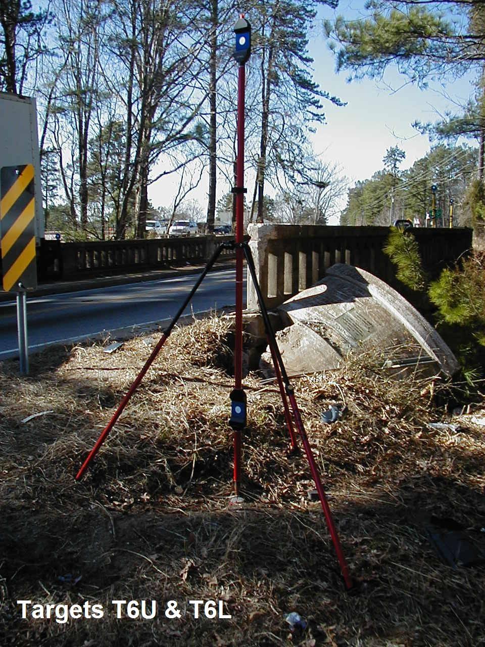
1 Module 7 Defining Coordinate Systems Introduction Objectives Outline of Topics Covered The use of coordinate systems is very important in managing 3D spatial data including point clouds. In this module you will learn how to create and manage coordinate systems. At the end of this lesson, you will: Be able to geo-reference a point cloud or set of point clouds to an assumed coordinate system Understand the difference between each method of setting the coordinate system Know how to save the new coordinate system Section Description Page 1 Understanding Scan Coordinates and Coordinate Systems 2 2 Setting Coordinates using Vertical Points, and Azimuth 4 3 Setting Coordinates using 13 Database to Use Use the previously modified data base: Tryon Road.imp Units in Feet. Coordinate labels: X, Y, & Z Default As-Scanned Coordinates The default setting of the coordinate axes during scanning with the Cyrax 2500 is with the origin of the coordinate axis at a point within the scanner. The orientation of the axes is dependent upon the position of the scanner. The default position of a Cyrax scan cloud is with the Y coordinate up, the Z axis in the opposite direction of the scan, and the X axis pointing to the right of the scanner. Use the Right Hand Rule with the index finger pointed UP Page 1 of 20
2 1 Understanding Scan Coordinates and Coordinate Systems General Discussion There are certain situations in 3D laser scanning where a full Registration for the purposes of geo-referencing is not necessary based on the deliverables required. For the registration process, a minimum of 3 points (within three axes - X,Y,Z) in the project must be known and scanned for the transformation (rotation and translation of the ScanWorlds) to work. Typically more than 3 points are used to allow for redundancy and reduction of errors. However, depending on the final deliverables, a full registration process may not be necessary. Examples of deliverables that might not require full Registration (for Geo-referencing) are: A 2D planimetric map (no topography or elevations) A 3D topographic map of a relatively small area (e.g. 200m X 200m) For these situations, Cyclone has the capability of setting the project coordinate system using a variety of methods described further in this document. These methods are listed below: Translation of existing coordinate system to user-defined reference point. Translation to new reference point, orientation measured by user entered azimuth Up direction set by vertical pair(s) of points, orientation by azimuth Up direction set by known elevation points (benchmarks), orientation by azimuth In each of these cases, the XYZ coordinate basis of the scanner is transformed into real world Cartesian coordinates that are either known (control) or assumed (defined by user). For each case, the minimum number of constraints is used to determine the new coordinate system, and there is little or no information to detect blunders. The user must be careful to use the best practices as described in this document to avoid misuse of these features. NOTE For 3D laser scanning surveys that require the data be georeferenced to an existing coordinate system, Cyra highly recommends that the standard Registration process be used with a redundant amount of control points. Page 2 of 20
3 When visualizing a single or registered point cloud as oriented in accordance with a world or conventional survey coordinates use the left hand rule. Cartesian coordinates [named after René Descartes], are a system for representing the relative positions of points in a plane or in space. In a three-dimensional space, a point is specified by three numbers (x,y, and z) representing the distances of the point from three intersecting straight lines (or planes), referred to as the x-axis and the y-axis and the z-axis. Each axis (or plane) is normal to the other two axes. Visualizing Cartesian Coordinates In the Cartesian coordinate system your thumb represents the +X axis, your index finger represents the +Y axis, and your middle finger represents the + Z axis. When Registered to Survey Coordinates use the Right hand Rule Visualizing Survey Coordinates In conventional survey coordinates your thumb represents Easting, your index finger represents North, and your middle finger represents Elevation. Page 3 of 20
 to establish a vertical reference on the site, along with")

4 Default Cyrax Point Cloud Coordinates for HDS 2500 Scanner Default Cyrax Point Cloud Coordinates for HDS 3000 Scanner 2 Setting Coordinates using Vertical Points, and Azimuth Using Twin- Target Pole Create New Project Folder Create New Registration In this lesson you will utilize a special Twin-Target Pole accessory (available from Cyra) to establish a vertical reference on the site, along with another point in the scan to establish the horizontal orientation from North. Since this method is based on a minimal number of constraints, it should only be used with a full understanding of the caveats and potential error sources. As with all surveying work, you should always include independent checks to verify the final solution. We will create a project with only two ScanWorlds, ScanWorld 1 and ScanWorld 7. Under the database Tryon Road.imp create a new Project Folder and re-name it to Coordinate Setting. (Create Project) Under the new Project folder named Coordinate Setting create a new Registration. (Create Registration) Rename it to Reg of SWs 1&7. Page 4 of 20

5 Set ScanWorld 7 to Home Register ONLY ScanWorlds 1 & 7 together using the existing target tie points. (Hint: Use the Add Auto Constraints function). Note how these two point clouds have been scanned from opposite sides of the bridge. Note that the default coordinate system of each ScanWorld is: Y Up; Z Opposite to scan direction; X to the right of the scanner. Set ScanWorld 7 as the Home ScanWorld Register the two ScanWorlds by clicking Registration Register. Reduce constraint weight of tie point T1 to 0.1. Re-register the ScanWorlds Register ScanWorlds 1 & 7 Create and open the new ModelSpace Figure 6-2 Create ScanWorld and Freeze Registration. Close Reg window. Then open a ModelSpace View for ScanWorld Registration SW1&7. See Figure 6-3. Rename the new ModelSpace and the new ModelSpace View to ModelSpace Reg 1&7. See Figure 6-4. Double-click on the ModelSpace view ModelSpace Reg 1&7 to open it. Page 5 of 20


6 Create new ModelSpace and ModelSpace Views Review the coordinate system Figure 6-3 Default ModelSpace Names Figure 6-4 ModelSpaces renamed Note the location of the origin and the general directions of the axes. The origin is in its default position the scan head for ScanWorld 7 since this was set as the Home ScanWorld during registration. The axes are aligned to how the scan head was oriented in ScanWorld 7. Click on any point and look in the lower part of the screen to view the coordinate. Notice that it is still in the Scanner coordinate system. Figure 6-4 The registered scan in its default coordinate system. Page 6 of 20


7 View ScanCloud from Above Rotate the view to look down on the scan from above. The view locks in the current coordinate systems top viewpoint. This is not a true top viewpoint according to the real world coordinate system, but rather a top view based on the orientation of the home scanner when the scan was made. Set New Coordinate System Select points for setting coordinate system Turn on Tie Point Annotations Figure 6-5 Orthographic Plan View Now we are going to Set a New Coordinate System. Using the targets shown in the ModelSpace, a new coordinate system can be created by selecting the points that will determine the origin, rotation, and translation of the new system. Zoom into the twin target pole assembly, located in the right side of ScanWorld 7. The top and bottom tie-points have been modeled (2 vertices) Select all vertices in the new registered ScanWorld by going to Set Selectables [Shift s] Check Vertex Click on Select Go to Tools Annotations Add/Edit Annotations Check the box to make the Target ID labels visible Close window Page 7 of 20


8 Turn on the Target ID Annotations Figure 6-6 Page 8 of 20


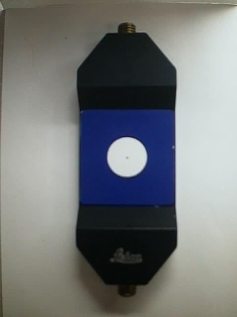
9 Select Vertices of Twin Target Pole Assembly Figure 6-7 Twin target pole assembly viewed in ModelSpace See above three illustrations of the components of the Twin Target Pole Assembly The twin target pole, even though set vertical in the field, may not look upright in the scan. This is because the scanner was not oriented to the vertical axis as determined by gravity. Select the vertex on the bottom (lower) target of the pole (t6l). Make sure that only the vertex is selected, and not a point in the point cloud. You can look at the status bar on the bottom of the screen to verify that you have selected a vertex. To make picking the line easier, either turn off the pickability of point clouds in the Set Selectable dialog, or zoom in closer to the vertex. Figure 6-8 Tie point t6l is selected Page 9 of 20
.")
10 Select Top Tie Point Zoom back out and multi-select the vertex at the top target of the pole. To multi-select, hold down the Shift key when picking the vertex or use the multi-pick mode. Select the azimuth point to determine horizontal orientation Now you have two points selected (the top and bottom of the twin target pole). These will be used to set the up direction for the new coordinate system. Now all we need is another point in the scan(s) that establishes an azimuth direction from tie point T6l with respect to North (or South) depending on your hemisphere. Select a third vertex (T4) to be used to set the orientation or rotation of the system to the North direction. In this case, we have measured the azimuth from the first point (with the twin target pole) to the target T4 on the bridge railing by using a compass. Don t forget to multi-select, as you want to keep the original two picks on the twin target pole. Figure 6-9 Select the azimuth point Page 10 of 20


11 Change Coordinate Axes Labels Change Coordinate Labels from X,Y,Z to N, E, & El. Set New Coordinate System From Points Figure 6-10 From the View menu, click on Coordinate System Set From Points... to display the Set Coordinate System From Pick Points dialog. Figure 8-11 Page 11 of 20
12 Enter Values in Set Coordinates from Pick Points Window The Dialog Box should Look Like This => Now that the picks have been made, you need to indicate which pick points will be used to set up the coordinate system; and what values to use for the origin coordinate and the azimuth. Notice that Cyclone automatically numbers the points in the order that they were picked. (The color of the letters is maaggeennt taa) In this example, points 1&2 are the bottom and top points of the twin target pole, and point 3 is the azimuth point T4. Enter the following values in the Dialog box: Reference Point = 1 (the bottom target on the twin target pole) Easting = ft (assumed) Northing = ft (assumed) Elevation = (assumed ground = ) Azimuth Point = 3 (the target on the bridge railing) Angle = 295 deg <N 65 E> (measured by compass) Top Point = 2 Bottom Point = 1 Figure8-12 Fill in the fields as shown above. Page 12 of 20
13 Once the coordinate data is entered, select OK. The coordinate system is now set for this ModelSpace using the coordinate information you provided. You can now check the coordinate values for other known points in the site plan below. You have now successfully geo-referenced the point cloud! Figure 6-13 Compare your results to the control coordinates in the sketch above 3 Setting Coordinates using Instead of relying on the twin-target pole to establish vertical, this exercise utilizes known benchmarks to establish a vertical reference on the site and also uses an additional point in the scan to establish the horizontal orientation from North. Since this method is based on a minimal number of constraints, it should only be used with a full understanding of the caveats and potential error sources. As with all surveying work, you should always include independent checks to verify the final solution. As done in the previous exercise we will again use two of the ScanWorlds from the last exercise to complete this exercise. Page 13 of 20


14 Open a new ModelSpace in the ScanWorld You are now to create a second new ModelSpace using ScanWorld 1 and ScanWorld 7. Do the following operations: Create and open a new ModelSpace in the same ScanWorld. From the Cyclone Navigator window click on the ModelSpace folder then click on Create ModelSpace or Right-Click on the ModelSpace folder and go to Create ModelSpace. Rename the ModelSpace to ModelSpace Reg 1&7B Create and open a ModelSpace View. Notice that the new ModelSpace is still in the Scanner Coordinate System Figure 6-13 Create and Open a New ModelSpace Figure 6-14 New ModelSpace View Page 14 of 20
 Two targets set over known benchmarks (CL & D) in that order Select all tie points and turn on the annotations for each tie point to show the target ID s.")
15 Select points for setting coordinate system Show all Tie Point Labels Select vertices This time we will select 5 points in the scan: The top/bottom targets on the twin-target pole The target to determine azimuth (T4) Two targets set over known benchmarks (CL & D) in that order Select all tie points and turn on the annotations for each tie point to show the target ID s. Select the vertex on the bottom (lower) target of the pole Make sure that only the vertex is selected, and not a point in the point cloud. You can look at the status bar on the bottom of the screen to verify that you have selected a vertex. Select the azimuth point to determine horizontal orientation Figure 6-14 Twin target pole viewed in ModelSpace Select the top vertex of the Twin Target Pole while holding down the Shift key or using the multi-pick mode. Now you have two points selected (the top and bottom of the twin target pole). This will NOT be used to mathematically set the up direction for the new coordinate system; however, they are needed to determine a unique solution for the new coordinate system. NOTE: Although it is recommended to use the twin-target pole for this method, any pair of points that represent a general vertical direction can be used for this method, for example a plumb bob and string. Page 15 of 20
16 Multi-select the tie point T4 to be used to set the orientation or rotation of the system to the North direction. Figure 6-15 Select the benchmark points Select two benchmark points, shown as Point CL & T1 in the Site Plan. These selections, in addition to the elevation of the reference point, will be used to establish vertical in your new coordinate system. The elevation of the vertices has already been computed up from the ground benchmark by applying a target height constant. Select the Points in this order: 1. Bottom of Twin Target Pole T6l 2. Top of Twin Target Pole T6u 3. Tie Point T4 4. Tie Point CL 5. Tie Point T1 Set From Points From the View menu, click Coordinate System Set From Points... to display the Set Coordinate System From Pick Points dialog. Page 16 of 20

17 Figure 6-16 We are almost finished. Now that the picks have been made, we need to tell Cyclone which ones will be used to set up the coordinate system; and what values to use for the origin coordinate, benchmarks and azimuth. Information to be entered Enter the following values in the Dialog box: Refer to Figures 9-16 and Reference Point = 1 (the bottom target on the twin target pole) Easting = ft Northing = ft Elevation = ft Azimuth Point = 3 (the tie point T4) Angle = 295 deg <N 65 E> (measured by compass) Top Point = 2 Bottom Point = 1 Elevation Point 1 = 4 (Tie Point CL1 on sketch) Elevation = m Elevation Point 2 = 5 (Tie Point T1 on sketch) Elevation = m Page 17 of 20


18 Enter Data into Fields Designations of Tie Points Figure 6-16 Correct Data Entered into Fields Figure 6-17 Page 18 of 20

19 Technical Notes Save the new coordinate system Once the coordinate data is entered, select OK. The coordinate system is now set for this ModelSpace using the coordinate information you provided. The vertical accuracy of resulting data points using this method is dependent on the accuracy of the benchmarks used and the accuracy of scanning the benchmarks It is recommended that 3 or 4 benchmarks be used as a check on the final solution. In addition, accuracy is also a function of the geometry of the benchmark points used with respect to the reference point. Ideally, the benchmark points should be at the extents of the project and should have a wide aspect ratio with respect to the reference point. For example, using points along the same line will result in poor elevation accuracy as you move away from the line. When you set the coordinate system using the procedures above, you are only setting it for that individual ModelSpace. If you would like to keep this coordinate system and set it as the default coordinate system for its parent ScanWorld, follow the procedure below: Set the New Coordinate System for Parent ScanWorld From the View menu, click Coordinate System Set ScanWorld Coordinate System A warning message will appear asking if you want to set the coordinate system for this ModelSpace s parent ScanWorld, select Yes You can see the results when you open a new ModelSpace in the same ScanWorld. Figure 6-18 Setting the new coordinate system for ScanWorld Page 19 of 20


20 Saving Other Coordinate Systems Using multiple user-defined coordinate systems can be very helpful in the navigation and analysis of large ModelSpaces. The User Coordinate Systems dialog is used to save, restore, and delete user-defined coordinate systems. To save the current coordinate system 1 From the View menu, point to Coordinate System, and then select Save Edit Coordinate Systems... to display the User Coordinate Systems dialog. 2 Click the Save icon. The Coordinate System Name dialog appears. Figure Enter a name for the current coordinate system, and then click OK. The current coordinate system is saved. Figure 6-20 End of Training Module 7 Page 20 of 20
Cyclone Tips and Tricks. Hexagon Geosystems Track June 2012
 Cyclone Tips and Tricks Hexagon Geosystems Track June 2012 Built-in Hotkeys Enhanced Working Format Open GL Modes There are some very powerful built-in viewing hotkeys in Cyclone. Here are some of them:
Leica Geosystems HDS. Welcome to CloudWorx 3.2 Tutorial. Cyclone CloudWorx 3.2 Tutorial Section I High-Definition Surveying
 8:08 Cyclone CloudWorx 3.2 Tutorial Section I Welcome to CloudWorx 3.2 Tutorial CloudWorx is the high-performance point cloud solution that enables you to load, render, analyze and extract information
CloudWorx for Intergraph SmartPlant Review 1.0 Tutorial High-Definition Surveying. Tutorial-Plant
 Tutorial-Plant CloudWorx 1.0 for Intergraph SmartPlant Review CloudWorx for Intergraph SmartPlant Review provides a dynamic and flexible way to work efficiently with large as-built point clouds within
Using Coordinate Systems
 Using Coordinate Systems In This Chapter 5 As you draw you use the coordinate system to specify points in the drawing. You can locate and use your own movable user coordinate system (UCS) for working on
DOWN PLUNGE CROSS SECTIONS
 GG303 Lab 7 10/6/10 1 DOWN PLUNGE CROSS SECTIONS I Main Topics A Cylindrical folds B Downplunge cross-section views C Apparent dip II Cylindrical folds A Surface of a cylindrical fold is parallel to a
Rational Numbers: Graphing: The Coordinate Plane
 Rational Numbers: Graphing: The Coordinate Plane A special kind of plane used in mathematics is the coordinate plane, sometimes called the Cartesian plane after its inventor, René Descartes. It is one
Parametric Modeling with. Autodesk Fusion 360. First Edition. Randy H. Shih SDC. Better Textbooks. Lower Prices.
 Parametric Modeling with Autodesk Fusion 360 First Edition Randy H. Shih SDC PUBLICATIONS Better Textbooks. Lower Prices. www.sdcpublications.com Powered by TCPDF (www.tcpdf.org) Visit the following websites
Parametric Modeling. With. Autodesk Inventor. Randy H. Shih. Oregon Institute of Technology SDC PUBLICATIONS
 Parametric Modeling With Autodesk Inventor R10 Randy H. Shih Oregon Institute of Technology SDC PUBLICATIONS Schroff Development Corporation www.schroff.com www.schroff-europe.com 2-1 Chapter 2 Parametric
Working with Plan Production ObjectsChapter1:
 Chapter 1 Working with Plan Production ObjectsChapter1: The lessons in this chapter guide you through the processes of creating and working with plan production objects. Plan production objects include
Lesson 1 Parametric Modeling Fundamentals
 1-1 Lesson 1 Parametric Modeling Fundamentals Create Simple Parametric Models. Understand the Basic Parametric Modeling Process. Create and Profile Rough Sketches. Understand the "Shape before size" approach.
What You ll See in This Chapter. Word Cloud. René Descartes. Introduction. Ian Parberry University of North Texas. Fletcher Dunn
 What You ll See in This Chapter Chapter 1: Cartesian Coordinate Systems Fletcher Dunn Valve Software Ian Parberry University of North Texas This chapter describes the basic concepts of 3D math. It is divided
McIDAS-V Tutorial Displaying Level II Radar Imagery updated July 2016 (software version 1.6)
") McIDAS-V Tutorial Displaying Level II Radar Imagery updated July 2016 (software version 1.6) McIDAS-V is a free, open source, visualization and data analysis software package that is the next generation
McIDAS-V Tutorial Displaying Level II Radar Imagery updated July 2016 (software version 1.6) McIDAS-V is a free, open source, visualization and data analysis software package that is the next generation
Module 4B: Creating Sheet Metal Parts Enclosing The 3D Space of Right and Oblique Pyramids With The Work Surface of Derived Parts
 Inventor (5) Module 4B: 4B- 1 Module 4B: Creating Sheet Metal Parts Enclosing The 3D Space of Right and Oblique Pyramids With The Work Surface of Derived Parts In Module 4B, we will learn how to create
COORDINATE TRANSFORMATION. Lecture 6
 COORDINATE TRANSFORMATION Lecture 6 SGU 1053 SURVEY COMPUTATION 1 Introduction Geomatic professional are mostly confronted in their work with transformations from one two/three-dimensional coordinate system
Beaumont Middle School Design Project April May 2014 Carl Lee and Craig Schroeder
 Beaumont Middle School Design Project April May 2014 Carl Lee and Craig Schroeder 1 2 SketchUp 1. SketchUp is free, and you can download it from the website www.sketchup.com. For some K12 use, see www.sketchup.com/3dfor/k12-education.
LESSON 2 MODELING BASICS
 LESSON 2 MODELING BASICS In this lesson we ll start to model a multi-story office building from scratch. We ll construct the base grid, create the two towers and place slabs between the stories. Also we
 Page 1 of 8 Tutorial Modeling a Bishop In this lesson you will model a bishop for the chess set. As with the rook, the base of the bishop has already been created. You will add the miter on top of the
START>PROGRAMS>ARCGIS>
 Department of Urban Studies and Planning Spring 2006 Department of Architecture Site and Urban Systems Planning 11.304J / 4.255J GIS EXERCISE 2 Objectives: To generate the following maps using ArcGIS Software:
Project curves, points, or sketches onto faces and planes.
 Project Curve Path: Curve tab > Derived Curve group > Project Curve Objectives Project curves, points, or sketches onto faces and planes. Prerequisites File tab > Start > Modeling Projecting Curves to
COMPUTER AIDED ARCHITECTURAL GRAPHICS FFD 201/Fall 2013 HAND OUT 1 : INTRODUCTION TO 3D
 COMPUTER AIDED ARCHITECTURAL GRAPHICS FFD 201/Fall 2013 INSTRUCTORS E-MAIL ADDRESS OFFICE HOURS Özgür Genca ozgurgenca@gmail.com part time Tuba Doğu tubadogu@gmail.com part time Şebnem Yanç Demirkan sebnem.demirkan@gmail.com
Autodesk Fusion 360 Training: The Future of Making Things Attendee Guide
 Autodesk Fusion 360 Training: The Future of Making Things Attendee Guide Abstract After completing this workshop, you will have a basic understanding of editing 3D models using Autodesk Fusion 360 TM to
Transformation Range of Points: Add to Point Numbers: Overwrite Existing Point Numbers: Use New Point Numbers: Store in New CRD File:
 Transformation This command allows you to translate, rotate, and/or scale points and linework in the current job. The Align option does all 3 (translate, rotate, scale) at once. Any point drawn on the
Parametric Modeling. with. Autodesk Inventor Randy H. Shih. Oregon Institute of Technology SDC
 Parametric Modeling with Autodesk Inventor 2009 Randy H. Shih Oregon Institute of Technology SDC PUBLICATIONS Schroff Development Corporation www.schroff.com Better Textbooks. Lower Prices. 2-1 Chapter
User s guide. November LSE S.r.l. All rights reserved
 User s guide November 2015 2015 LSE S.r.l. All rights reserved WARNING In writing this manual every care has been taken to offer the most updated, correct and clear information possible; however unwanted
Equipment Support Structures
 Equipment Support Structures Overview Conventions What's New? Getting Started Setting Up Your Session Creating a Simple Structural Frame Creating Non-uniform Columns Creating Plates with Openings Bracing
Technique or Feature Where Introduced
 Part 6: Keypad 4 Mirrored features Patterned features First extrusion Rounded corners In the earpiece part, you defined a radial pattern, one that created new instances of a feature at intervals around
Equipment Support Structures
 Page 1 Equipment Support Structures Preface Using This Guide Where to Find More Information Conventions What's New? Getting Started Setting Up Your Session Creating a Simple Structural Frame Creating Non-uniform
WebShare Cloud Basics
 3D Laser Scanning WebShare Cloud Basics WebShare Cloud Instructions The purpose of this document is to walk you through the process of using WebShare Cloud if you have been invited to view information.
TLS Parameters, Workflows and Field Methods
 TLS Parameters, Workflows and Field Methods Marianne Okal, UNAVCO June 20 th, 2014 How a Lidar instrument works (Recap) Transmits laser signals and measures the reflected light to create 3D point clouds.
An Introduction to Autodesk Inventor 2010 and AutoCAD Randy H. Shih SDC PUBLICATIONS. Schroff Development Corporation
 An Introduction to Autodesk Inventor 2010 and AutoCAD 2010 Randy H. Shih SDC PUBLICATIONS Schroff Development Corporation www.schroff.com 2-1 Chapter 2 Parametric Modeling Fundamentals Create Simple Extruded
Autodesk Fusion 360: Model. Overview. Modeling techniques in Fusion 360
 Overview Modeling techniques in Fusion 360 Modeling in Fusion 360 is quite a different experience from how you would model in conventional history-based CAD software. Some users have expressed that it
OBJECT MANAGER PACKAGE USER S GUIDE
 OBJECT MANAGER PACKAGE USER S GUIDE 1 CONTENT I. Introduction... 3 II. Installation... 3 III. Using the plugins... 4 a- General... 4 b- Object properties manager... 4 c- Pipe manager... 6 d- Plane manager...
Welcome to MicroStation
 Welcome to MicroStation Module Overview This module will help a new user become familiar with the tools and features found in the MicroStation design environment. Module Prerequisites Fundamental knowledge
Creating T-Spline Forms
 1 / 28 Goals 1. Create a T-Spline Primitive Form 2. Create a T-Spline Revolve Form 3. Create a T-Spline Sweep Form 4. Create a T-Spline Loft Form 2 / 28 Instructions Step 1: Go to the Sculpt workspace
Module 4A: Creating the 3D Model of Right and Oblique Pyramids
 Inventor (5) Module 4A: 4A- 1 Module 4A: Creating the 3D Model of Right and Oblique Pyramids In Module 4A, we will learn how to create 3D solid models of right-axis and oblique-axis pyramid (regular or
An Introduction to Autodesk Inventor 2013 and AutoCAD
 An Introduction to Autodesk Inventor 2013 and AutoCAD 2013 Randy H. Shih SDC PUBLICATIONS Schroff Development Corporation Better Textbooks. Lower Prices. www.sdcpublications.com Visit the following websites
NYSAPLS 50 th Anniversary Surveyor's Conference and Exhibition
 Field to Finish - 3D Modeling and DTM (InRoads Survey and PowerSurvey Basics) Presenter: Gerald B. Danzy, Software/Product Consultant Bentley Systems, Incorporated 685 Stockton Drive Exton, PA 19341 www.bentley.com
v Overview SMS Tutorials Prerequisites Requirements Time Objectives
 v. 12.2 SMS 12.2 Tutorial Overview Objectives This tutorial describes the major components of the SMS interface and gives a brief introduction to the different SMS modules. Ideally, this tutorial should
GEOMETRY. TI-Nspire Help and Hints. 1 Open a Graphs and Geometry page. (Press c 2 ).
.") GEOMETRY TI-Nspire Help and Hints 1 Open a Graphs and Geometry page. (Press c 2 ). 2 You may need to save a current document you have been working on. Save or press e to move the cursor to No and press.
GEOMETRY TI-Nspire Help and Hints 1 Open a Graphs and Geometry page. (Press c 2 ). 2 You may need to save a current document you have been working on. Save or press e to move the cursor to No and press.
Autodesk Inventor - Basics Tutorial Exercise 1
 Autodesk Inventor - Basics Tutorial Exercise 1 Launch Inventor Professional 2015 1. Start a New part. Depending on how Inventor was installed, using this icon may get you an Inch or Metric file. To be
Control the Workplane
 Control the Workplane This tutorial outlines the procedures to understand and control the user coordinate system (UCS). You can realign and reorient the UCS to create and modify 3D objects on 2D workplanes
7. r = r = r = r = r = 2 5
 Exercise a: I. Write the equation in standard form of each circle with its center at the origin and the given radius.. r = 4. r = 6 3. r = 7 r = 5 5. r = 6. r = 6 7. r = 0.3 8. r =.5 9. r = 4 0. r = 3.
Lesson 1: Creating T- Spline Forms. In Samples section of your Data Panel, browse to: Fusion 101 Training > 03 Sculpt > 03_Sculpting_Introduction.
 3.1: Sculpting Sculpting in Fusion 360 allows for the intuitive freeform creation of organic solid bodies and surfaces by leveraging the T- Splines technology. In the Sculpt Workspace, you can rapidly
Intersecting Lamina. To complete this model you should have a working knowledge of Solidworks 2006/2009.
 Prerequisite knowledge Focus of lesson Problem To complete this model you should have a working knowledge of Solidworks 2006/2009. This lesson focuses on using SolidWorks to solve a geometrical problem.
Most as-built information is still manually collected. Today s Design Market
 Agenda 1. Overview of 3D laser scanning 2. HDS 3D Laser scanning applications Leica ScanStation2 True Color Scan 3. Demonstration of HDS & Trueview 4. Questions and Answers The advanced 3D Laser Scanning
SiteAware Viewer. Quick Start Guide
 SiteAware Viewer Quick Start Guide Login Screen 1. Enter SiteAware provided username (an email address) and password 2. Click Login 3. Click Forgot Password to request a password reset 4. Sign Up option
Three-Dimensional Laser Scanner. Field Evaluation Specifications
 Stanford University June 27, 2004 Stanford Linear Accelerator Center P.O. Box 20450 Stanford, California 94309, USA Three-Dimensional Laser Scanner Field Evaluation Specifications Metrology Department
Table Of Contents. Introduction Installation Included Materials System Requirements Quick Start... 9
 Cyclone 5.8 Table Of Contents Introduction... 3 Cyclone Software Introduction... 3 Installation... 5 Included Materials... 5 System Requirements... 5 Installing Cyclone... 6 Obtaining your Cyclone License...
Binoculars. with. Digital Compass. Instruction Manual. Model: Lit. #: /08-12
 Binoculars with Digital Compass Model: 137570 Instruction Manual Lit. #: 98-1192/08-12 Right Eyepiece Focus Compass Power Switch Battery Cover Left Eyepiece Focus Parts Reference Tripod Attachment Socket
Chapter 2 Parametric Modeling Fundamentals
 2-1 Chapter 2 Parametric Modeling Fundamentals Create Simple Extruded Solid Models Understand the Basic Parametric Modeling Procedure Create 2-D Sketches Understand the Shape before Size Approach Use the
Flair Geometry Editor Part I. Beginners FLUKA Course
 Flair Geometry Editor Part I Beginners FLUKA Course Starting the Geometry Editor Click on icon or from Menu View Geometry Editor or with [F4] shortcut Either start flair with option -g 2 Geometry editor
Producing Project Deliverables: Creating a Plan Set
 Practice Workbook This workbook is designed for use in Live instructor-led training and for OnDemand selfstudy. The explanations and demonstrations are provided by the instructor in the classroom, or in
SurvNET Lesson One - Processing an Assumed Coordinate System 2D Total Station Network
 SurvNET Lesson One - Processing an Assumed Coordinate System 2D Total Station Network This tutorial is divided into two lessons covering the process of reducing and adjusting raw survey data into final
Revit Architecture 2015 Basics
 Revit Architecture 2015 Basics From the Ground Up Elise Moss Authorized Author SDC P U B L I C AT I O N S Better Textbooks. Lower Prices. www.sdcpublications.com Powered by TCPDF (www.tcpdf.org) Visit
Doc #: IDI06-11F Rev: 1.3 Issued: 22/02/18. Well Seeker PRO How To Guide Rev 1.3. Page 1 of 26
 Well Seeker PRO How To Guide Rev 1.3 Page 1 of 26 Contents 1.0 - Getting Started... 4 1.1 - Display... 4 2.0 - Creating a new Well... 5 2.1 - Unit Selection... 5 2.2 - New Instant Plan / Survey... 6 2.3
TLS Parameters, Workflows and Field Methods
 TLS Parameters, Workflows and Field Methods Marianne Okal, UNAVCO GSA, September 23 rd, 2016 How a Lidar instrument works (Recap) Transmits laser signals and measures the reflected light to create 3D point
Lab 6: Transforming Spatial Data
 Lab 6: Transforming Spatial Data Objectives: The primary objectives of this lab are to georeference a raster dataset and to create GIS data by digitizing features from an image as a backdrop. Specifics:
Computation of Slope
 Computation of Slope Prepared by David R. Maidment and David Tarboton GIS in Water Resources Class University of Texas at Austin September 2011, Revised December 2011 There are various ways in which slope
CE 260 SURVEYING CHAPTER 5 THEODOLITES
 CE 260 SURVEYING CHAPTER 5 THEODOLITES General Background: Theodolites or Transits are surveying instruments designed to precisely measure horizontal and vertical angles. 1 They are used to establish straight
Leica Cyclone 5.4 Technical Specifications
 Leica Cyclone 5.4 Technical Specifications HDS Scanner control and operation Scan Scan Scan Register Model Survey Viewer Acquire and display image Acquire image at specified resolution (high, medium, low)
Transformations. Lesson Summary: Students will explore rotations, translations, and reflections in a plane.
 Transformations Lesson Summary: Students will explore rotations, translations, and reflections in a plane. Key Words: Transformation, translation, reflection, rotation Background knowledge: Students should
SMS v D Summary Table. SRH-2D Tutorial. Prerequisites. Requirements. Time. Objectives
 SMS v. 12.3 SRH-2D Tutorial Objectives Learn the process of making a summary table to compare the 2D hydraulic model results with 1D hydraulic model results. This tutorial introduces a method of presenting
A stratum is a pair of surfaces. When defining a stratum, you are prompted to select Surface1 and Surface2.
 That CAD Girl J ennifer dib ona Website: www.thatcadgirl.com Email: thatcadgirl@aol.com Phone: (919) 417-8351 Fax: (919) 573-0351 Volume Calculations Initial Setup You must be attached to the correct Land
CGWAVE Analysis SURFACE WATER MODELING SYSTEM. 1 Introduction
 SURFACE WATER MODELING SYSTEM CGWAVE Analysis 1 Introduction This lesson will teach you how to prepare a mesh for analysis and run a solution for CGWAVE. You will start with the data file indiana.xyz which
Solid Problem Ten. In this chapter, you will learn the following to World Class standards:
 C h a p t e r 11 Solid Problem Ten In this chapter, you will learn the following to World Class standards: 1. Sketch of Solid Problem Ten 2. Starting a 3D Part Drawing 3. Modifying How the UCS Icon is
TerraScan New Features
 www.terrasolid.com TerraScan New Features Arttu Soininen 23.01.2018 Import Scanner Positions for Trajectories File / Import scanner positions menu command in Manage Trajectories reads scanner positions
The Department of Construction Management and Civil Engineering Technology CMCE-1110 Construction Drawings 1 Lecture Introduction to AutoCAD What is
 The Department of Construction Management and Civil Engineering Technology CMCE-1110 Construction Drawings 1 Lecture Introduction to AutoCAD What is AutoCAD? The term CAD (Computer Aided Design /Drafting)
Trigonometry * Scott Starks. 1 Trigonometry
 OpenStax-CNX module: m38633 1 Trigonometry * Scott Starks This work is produced by OpenStax-CNX and licensed under the Creative Commons Attribution License 3.0 1 Trigonometry 1.1 Introduction Trigonometry
Autodesk Inventor Design Exercise 2: F1 Team Challenge Car Developed by Tim Varner Synergis Technologies
 Autodesk Inventor Design Exercise 2: F1 Team Challenge Car Developed by Tim Varner Synergis Technologies Tim Varner - 2004 The Inventor User Interface Command Panel Lists the commands that are currently
Quick Crash Scene Tutorial
 Quick Crash Scene Tutorial With Crash Zone or Crime Zone, even new users can create a quick crash scene diagram in less than 10 minutes! In this tutorial we ll show how to use Crash Zone s unique features
An Introduction to Autodesk Inventor 2012 and AutoCAD Randy H. Shih SDC PUBLICATIONS. Schroff Development Corporation
 An Introduction to Autodesk Inventor 2012 and AutoCAD 2012 Randy H. Shih SDC PUBLICATIONS www.sdcpublications.com Schroff Development Corporation Visit the following websites to learn more about this book:
Image georeferencing is the process of developing a model to transform from pixel coordinates into GIS coordinates such as meters on the ground.
 Image georeferencing is the process of developing a model to transform from pixel coordinates into GIS coordinates such as meters on the ground. Image rectification is the process of using your georeferencing
Module 6B: Creating Poly-Conic Sheet Metal Pieces for a Spherical Space
 1 Module 6B: Creating Poly-Conic Sheet Metal Pieces for a Spherical Space In Module 6B, we will learn how to create a folded 3D model of an approximate 2D flat pattern for a 120-inch or 10-foot diameter
Editing Parcel Fabrics Tutorial
 Editing Parcel Fabrics Tutorial Copyright 1995-2010 Esri All rights reserved. Table of Contents Tutorial: Getting started with parcel fabric editing...................... 3 Tutorial: Creating new parcels
v SMS 11.2 Tutorial Overview Prerequisites Requirements Time Objectives
 v. 11.2 SMS 11.2 Tutorial Overview Objectives This tutorial describes the major components of the SMS interface and gives a brief introduction to the different SMS modules. Ideally, this tutorial should
MODULE 1 BASIC LIDAR TECHNIQUES
 MODULE SCENARIO One of the first tasks a geographic information systems (GIS) department using lidar data should perform is to check the quality of the data delivered by the data provider. The department
Creating a T-Spline using a Reference Image
 1 / 17 Goals Learn how to create a T-Spline using a Reference Image. 1. Insert an image into the workspace using Attach Canvas. 2. Use Calibrate to set the proper scale for the reference image. 3. Invoke
Name Date Class. When the bases are the same and you multiply, you add exponents. When the bases are the same and you divide, you subtract exponents.
 2-1 Integer Exponents A positive exponent tells you how many times to multiply the base as a factor. A negative exponent tells you how many times to divide by the base. Any number to the 0 power is equal
TPC Desktop Series. Geodetic Learning Guide
 TPC Desktop Series Geodetic Learning Guide 1/18 NOTICE The information in this document is subject to change without notice. TRAVERSE PC. Inc. assumes no responsibility for any errors that may appear in
TPC Desktop Series. Alignments Learning Guide 1/18
 TPC Desktop Series Alignments Learning Guide 1/18 NOTICE The information in this document is subject to change without notice. TRAVERSE PC. Inc. assumes no responsibility for any errors that may appear
Lecture 21 - Chapter 8 (Raster Analysis, part2)
") GEOL 452/552 - GIS for Geoscientists I Lecture 21 - Chapter 8 (Raster Analysis, part2) Today: Digital Elevation Models (DEMs), Topographic functions (surface analysis): slope, aspect hillshade, viewshed,
GEOL 452/552 - GIS for Geoscientists I Lecture 21 - Chapter 8 (Raster Analysis, part2) Today: Digital Elevation Models (DEMs), Topographic functions (surface analysis): slope, aspect hillshade, viewshed,
MatterHackers. How to make a 3D model using Google Earth. Written By: Ryan Lutz. How to make a 3D model using Google Earth data
 MatterHackers How to make a 3D model using Google Earth data Written By: Ryan Lutz 2017 matterhackers.dozuki.com Page 1 of 20 INTRODUCTION EDIT 7/25/17: Sadly, Sketchup has changed the map service they
Leica High-Definition Surveying Systems. Leica HDS3000. The Industry Standard for High-Definition Surveying
 Leica High-Definition Surveying Systems Leica HDS3000 The Industry Standard for High-Definition Surveying HDS High-Definition Surveying TM : Laser Scanning Redefined High-Definition Surveying, or HDS,
The Leica HDS Family. The Right Tool for the Job HDS3000 HDS2500 HDS4500. Cyclone & CloudWorx. Press the QuickScan button to define the field-of-view.
 HDS2500 High accuracy scanner, ideal for fixed or raised installations when leveled tripod mounting is not practical, or areas with less stringent field-of-view requirements. The Leica HDS Family Time-of-flight
Chapters 1-4: Summary
 Chapters 1-4: Summary So far, we have been investigating the image acquisition process. Chapter 1: General introduction Chapter 2: Radiation source and properties Chapter 3: Radiation interaction with
Navigation coordinate systems
 Lecture 3 Navigation coordinate systems Topic items: 1. Basic Coordinate Systems. 2. Plane Cartesian Coordinate Systems. 3. Polar Coordinate Systems. 4. Earth-Based Locational Reference Systems. 5. Reference
Geometry: Conic Sections
 Conic Sections Introduction When a right circular cone is intersected by a plane, as in figure 1 below, a family of four types of curves results. Because of their relationship to the cone, they are called
Working with the Dope Sheet Editor to speed up animation and reverse time.
 Bouncing a Ball Page 1 of 2 Tutorial Bouncing a Ball A bouncing ball is a common first project for new animators. This classic example is an excellent tool for explaining basic animation processes in 3ds
Chapter -7- Traversing. 1/28/2018 Assistant Lecturer / Asmaa Abdulmajeed 1. Contents
 Ishik University Sulaimani Civil Engineering Department Surveying II CE 215 Chapter -7- Traversing 1/28/2018 Assistant Lecturer / Asmaa Abdulmajeed 1 Contents 1. Traversing 2. Traversing Computations 3.
Convert Local Coordinate Systems to Standard Coordinate Systems
 BENTLEY SYSTEMS, INC. Convert Local Coordinate Systems to Standard Coordinate Systems Using 2D Conformal Transformation in MicroStation V8i and Bentley Map V8i Jim McCoy P.E. and Alain Robert 4/18/2012
TLS Data Processing and Exploration Manual
 Katherine Shervais (UNAVCO), Marin Clark (University of Michigan) Collecting data in the field is only the first step in the complete TLS workflow. This manual will take you through the skills needed to
Georeferencing and Digitizing
 INTRODUCTION There is a great deal of geographic data available in formats that cannot be immediately integrated with other GIS data. In order to use these types of data in GIS it is necessary to align
Piping Design. Site Map Preface Getting Started Basic Tasks Advanced Tasks Customizing Workbench Description Index
 Piping Design Site Map Preface Getting Started Basic Tasks Advanced Tasks Customizing Workbench Description Index Dassault Systèmes 1994-2001. All rights reserved. Site Map Piping Design member member
Lesson 7 Determining Direction. Key Terms. azimuth back azimuth degree grid azimuth grid north magnetic azimuth magnetic north true north
 Lesson 7 Determining Direction U.S. ARMY Key Terms J R O T C azimuth back azimuth degree grid azimuth grid north magnetic azimuth magnetic north true north WHAT YOU WILL LEARN TO DO Calculate direction
TLS Parameters, Workflows and Field Methods
 TLS Parameters, Workflows and Field Methods Marianne Okal, UNAVCO GSA, October 20 th, 2017 How a Lidar instrument works (Recap) Transmits laser signals and measures the reflected light to create 3D point
Views of a 3-D Clevis
 LESSON 5 Views of a 3-D Clevis Objectives: To become familiar with different view options. To create and modify z-axis and arbitrary clipping planes. PATRAN301ExerciseWorkbook-Release7.5 5-1 5-2 PATRAN
LESSON 6: DETERMINING DIRECTION
 LESSON 6: DETERMINING DIRECTION PURPOSE Directions play an important role in everyday life. People oftentimes express them as right, left, straight ahead, and so forth; but then the question arises, to
GIS LAB 8. Raster Data Applications Watershed Delineation
 GIS LAB 8 Raster Data Applications Watershed Delineation This lab will require you to further your familiarity with raster data structures and the Spatial Analyst. The data for this lab are drawn from
REVIT ARCHITECTURE 2016
 Page 1 of 6 REVIT ARCHITECTURE 2016 Revit Architecture 2016: CREATE A CHAMFERED COLUMN COMPONENT About creating a chamfered column family typical to the Victorian cottage style. Add the column to your
Camera Calibration for Video See-Through Head-Mounted Display. Abstract. 1.0 Introduction. Mike Bajura July 7, 1993
 Camera Calibration for Video See-Through Head-Mounted Display Mike Bajura July 7, 1993 Abstract This report describes a method for computing the parameters needed to model a television camera for video