Topic Training Load generators
|
|
|
- Austin Arnold
- 5 years ago
- Views:
Transcription


1 Topic Training Load generators
2 Topic Training Load generators All information in this document is subject to modification without prior notice. No part of this manual may be reproduced, stored in a database or retrieval system or published, in any form or in any way, electronically, mechanically, by print, photo print, microfilm or any other means without prior written permission from the publisher. SCIA is not responsible for any direct or indirect damage because of imperfections in the documentation and/or the software. Copyright 2015 SCIA nv. All rights reserved. 2
3 Table of contents Table of contents Introduction... 5 Plane generator... 6 Load panels... 9 Load to panel nodes... 9 Load panel to edges Panel to edges and beams Panel with parallel beams Free loads D Wind- and snow generators Wind generator Snow generator Wind & Snow generator D Wind Generator Mobile loads Principle Load system Train Loads References and literature
4 Topic Training Load generators 4
5 Introduction Introduction This course will explain the principles and the use of all different load generators. Most of the options in the course can be calculated in SCIA Engineer with the Concept edition. For some functionality an extra module (or edition) is required, but this will always be indicated in those paragraphs. 5

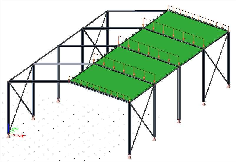
6 Topic Training Load generators Plane generator The plane generator is a tool which automatically transforms a defined area load into line loads acting on beams located in the specified plane. This generator can be used for flat frames which are subjected to a continuous area load. With this generator, it is no longer needed to manually determine the load widths and calculate the line loads. Example: Load Generators.esa This example consists of a simple steel hall: The self weight of the structure is automatically calculated by SCIA Engineer. The weight of the roof will be inserted manually using the Plane generator in the Load menu. Load cases: Self Weight (permanent) Roof Weight (permanent), -1 kn/m²


7 Plane generator By inserting an area load using the plane generator, all beams in the specified plane are loaded. This can be changed afterwards. With the option Update beams selection, all beams that have to be loaded can be selected. By using the action Refresh, the area load can be recalculated into line loads on the selected beams. After clicking on Calculate, the areas for the distribution of the load are calculated. The boundaries are indicated by the red lines. Notes: The last step, to recalculate the area load into line loads on the beams, will be automatically done during the calculation of the project. Both loads, the original area load and the generated line loads, can be displayed graphically. This can be done by changing the View parameters for the loads:

8 Topic Training Load generators
.")
9 Load panels Load panels Load panels are entities which are not taken into account in the FEM calculation (Finite Element Method Calculation). This means that load panels: Have no self weight Do have a certain stiffness to distribute the loads to the correct members (nodes, beams, plate edges,...). This stiffness is not taken into account for the stiffness of the structure. All type of loads can be inserted on load panels: point loads, line loads, surface loads,.... The load panels can be found in the Structure menu. There are 4 types of load panels available in SCIA Engineer: Load to panel nodes Load to panel edges Load to panel edges and beams Panel with parallel beams Load to panel nodes With this tool, the loads introduced on the panel, will be distributed to the nodes of the load panel. The parameters to be chosen: Name: each element has a unique name. Panel type: the types are listed above. Load transfer direction: it can be chosen whether the loads should be distributed in one or all directions. LCS type: a load panel has its own local coordinate system. This system can be changed. Swap orientation: the direction of the local Z axis can be inverted. LCS Angle [deg]: the local axes can be rotated.

10 Topic Training Load generators Layer: a layer can be chosen for each element/panel. Selection of entities: o All: all nodes of the load panel will be loaded o User selection: the user can select the nodes of the load panel that should be loaded. In this example, small load panels will be inserted on each part of the roof. An area load of -1 kn/m² will be placed on each load panel. This can be done in the Load menu, using the option Surface load, on 2D member.


11 Load panels These area loads need to be distributed to the nodes of the load panels. This can be done by selecting the load panels and using the action Generate loads. Afterwards, the point forces are generated on the nodes of the load panels.

12 Topic Training Load generators Note It is not necessary to select all the load panels and use the option Generate loads. The loads are automatically generated during the calculation of the project. Load panel to edges With this tool, the loads introduced on the panel, will be distributed to the edges of the load panel. The parameters to be chosen are explained in the previous chapter (Load panel to nodes). In this example, the Load transfer direction is set to X (LCS panel). That way, the correct beams are loaded. Analogously to the previous example, small load panels are inserted.
13 Load panels These load panels will be loaded with area loads of -1 kn/m². This can be done in the Load menu using the option Surface load, on 2D member. Next, the area loads can be transformed into line loads on the beams by selecting the load panels and using the action Generate loads.

14 Topic Training Load generators Since the beams in the middle of the roof have a load panel on each side, these beams are loaded twice with the same line load. Note It is not necessary to select all the load panels and use the option Generate loads. The loads are automatically generated during the calculation of the project.

15 Load panels Panel to edges and beams With this tool, the loads introduced on the panel, will be distributed to the edges of the load panel and to the supporting beams of the panel. Most of the parameters to be chosen are already explained in previous chapters. The parameters specific for this type of load panel will be discussed: Load transfer direction: o o o X direction of the panel LCS Y direction of the panel LCS All directions of the panel LCS. When this option is chosen, a percentage has to be inserted for both directions. o If one direction is chosen (X or Y of the panel LCS), there is an extra option, namely Max. Angle for transfer [deg]. If this angle is set to zero, only beams that are perpendicular to the chosen transfer direction can be loaded. Load transfer method: o Standard: all beams are loaded equally loaded. The user have to give in the load factors.

![Eccentricity of members [m]: also the members which have a position between this eccentricity above or beneath the](/docs-images/83/87827413/images/16-1.jpg "plane of the load panel, will be loaded.")

16 Topic Training Load generators o Accurate (FEM): the finite element calculation is used for the distribution of the area load to line loads on the edges/beams. Max. Eccentricity of members [m]: also the members which have a position between this eccentricity above or beneath the plane of the load panel, will be loaded. In this example 2 load panels will be inserted with the following properties: These load panels will be loaded with an area load of -1 kn/m². The loads can be inserted in the Load menu with the option Surface load, on 2D member. Afterwards, the load panels can be selected. With the action Generate loads, the area loads will be recalculated into line loads on the beams.
17 Load panels Since the Accurate (FEM) load transfer method is used, the loads are generated correctly without the need for the user to insert the load factors. Panel with parallel beams With this option, a load panel can be inserted directly with supporting beams. The beams are placed in the X direction of the panel LCS, and the load transfer is done in the Y direction of the panel LCS. A load panel with parallel beams will be inserted with the following parameters:
.")
18 Topic Training Load generators Most of the parameters to be chosen are already explained in previous chapters. The parameters specific for this type of load panel will be discussed: Type: specifies the type of the plate (plate, wall or shell). The chosen type has for instance an influence on the check according to the code (future development). Analysis model: only Standard is available. Material: a material can be chosen for the calculation of the self weight of the panel/plate (future development). FEM model: only Panel with beams is available Thickness [mm]: the thickness of the plate has to be given. This thickness has an influence on: o o The eccentricity of the beams The self weight of the panel (future development) Member system-plane at: center, top or bottom. Eccentricity z [mm]: if needed, an extra eccentricity can be inserted. And for the Beam layout: Position: the position of the beams can be defined in several ways. o o o o Distance: distance between the beams Number: the amount of beams Width: the part of the panel that has to be carried by the beams Generic: the distance/width does not have to be same for all beams First/Last offset [m]: the offset of the first/last beam. Switch offsets: to switch between the possibility to give in the first or last offset. Distance/Width/Number: the distance between the beams, the part of the panel that has to be carried by the beams or the amount of beams.

19 Load panels First/Last beam: the option to use/not use the first/last beam. Position in plate: specifies the position of the beam in the panel. Alignment: o o o Bottom: the beams are attached to the lower surface of the panel. Centre: the axis of the beam is located at the same level as the center plane of the panel. Top: the beams are attached to the upper surface of the panel. Beams eccentricity Z [mm]: defines the eccentricity of the beams. Select all beams to generator: all the beams will be loaded by the generated loads. In this example, one load panel with parallel beams will be inserted to show principle. The parameters can are viewed on the previous page. After modeling this panel, the parameters for the beams are asked for. In this example the IPE 100 profile is chosen. This load panel will be loaded with a surface load of -0,30 kn/m² in the global X direction (load case X):


20 Topic Training Load generators Afterwards, the panel can be selected and by clicking on the action button Load generation, the surface load will be distributed to the beams:
21 Free loads Free loads Free loads are related to 2D members, flat or curved (plates, walls, shells, load panels,...). Definition of free loads is composed of their geometry, which is independent on geometry of structural members, direction of load effect and a list of 2D members which are influenced by the free loads. Free loads are in fact easy load generators. A free load differs from a regular load by the fact that it is NOT attributed as an additional data to a specific 2D member. Since free loads do not have to be inserted on the entities itself, multiple loads can be generated using only one free load. This is illustrated with an example of a swimming pool. Example: Free Loads.esa In this example, two swimming pools are modeled (rectangular and circular). Both structures are supported by surface supports. Surface supports are always placed on the negative site of the local Z axis of the 2D element. For that reason, the positive direction of the local Z axis for each wall element should be pointing towards the inside of the pool. If this is not the case, the option Swap Orientation can be used in the property window of the 2D element.


22 Topic Training Load generators There are two load cases: Self Weigth (Permanent) Water pressure (Variable) After the load cases are defined, the water pressure can be inserted in the Load menu, using a Surface load, free. A free surface load can only be inserted in the working plane of the UCS (User Coordinate System). For that reason, it can be necessary to change the UCS. This can be done through Tools > UCS. In this example, the YZ workplane is chosen, to be able to insert the water pressure on the walls of the swimming pools.

23 Free loads It is the intention to load all walls (4 walls of the rectangular pool and 1 wall of the circular pool), by only introducing one free surface load. To be able to do this, the Z axis of the LCS of all walls, needs to be pointing to the inside of the pool. In this project, this is already done by changing the LCS of 2 walls by inserting the surface supports. Next the Free surface load can be inserted. Explanation of all parameters: Name: each element in SCIA Engineer has a unique name, also the loads. Direction: the direction in which the loads have to be generated. Type: this load will be introduced as o force. In some cases also self weight can be chosen. Distribution: o o o o Uniform: one constant value for the complete surface load. Dir X: a variable course of the free surface load in the direction X of the member LCS. Dir Y: a variable course of the free surface load in the direction Y of the member LCS. 3 points: a variable course of the free surface, according to 3 points chosen by the user. q [kn/m²]: the value of the load in kn/m² (more values if there is a variable course). Validity: Every free surface load has its own member LCS. Which elements should be loaded by the generated loads, depends on the validity. This validity applies to the Z axis of the free surface load LCS. o All: all 2D members on both sides of the free surface load will be loaded with the generated loads.
, can be loaded. Z (incl.")
24 Topic Training Load generators o o o o o o Select: o o System: o o o Z: only the elements situated under the free load (situated in the half-space defined by the negative Z direction of the free load LCS), can be loaded. Z (incl. 0): only the elements situated under and in the plane of the free load (situated in the half-space defined by the negative Z direction of the free load LCS), can be loaded. Z = 0: only the elements situated in the plane of the free surface load can be loaded. +Z: only the elements situated above the free load (situated in the half-space defined by the positive Z direction of the free load LCS), can be loaded. +Z (incl. 0): only the elements situated above and in the plane of the free load (situated in the half-space defined by the positive Z direction of the free load LCS), can be loaded. From-to: only the elements within a given interval can be loaded. Auto: all the elements, which correspondent with the validity, will be loaded. Select: the user can select the elements, which correspondent with the validity, to be loaded. GCS: the direction of the load according to the GCS (Global Coordinate System). Member LCS: the direction of the load according to the member LCS (Local Coordinate System). Load LCS: the direction of the load according to the load LCS. Location: length or projection (= only possible when System GCS is used). In this example, the following parameters are used: Since the value of the loads has to be 0 at the top and -25 at the bottom, it is necessary to use this order of nodes by drawing the free surface load: First point, a node at the top of the swimming pool. Second point, a node at the bottom of the swimming pool.

25 Free loads Since all walls need to be loaded by this water pressure, the walls can be selected using the action Update 2D member selection in the property window of the free surface load. To end the selection functionality, click Esc. Next, the action button Generate loads can be used to generated the loads on all selected 2D elements.

26 Topic Training Load generators Now all walls are loaded by the water pressure, by inserting only one free surface load.


27 2D Wind- and snow generators 2D Wind- and snow generators In this chapter, the wind and snow generator are explained. To be able to use this generators, the functionality Climatic loads should be used. In the next tab, the wind and snow load should be chosen (according to the code or user defined).

28 Topic Training Load generators There are three types of climatic load generators for 2D frames in SCIA Engineer: Wind generator Snow generator Wind & snow generator For all these load generators, the example 2D climatic generators is used. Example: 2D climatic generators.esa Wind generator Since there are no load cases automatically created by the wind generator, these have to be created manually. Load cases: Self Weight (Permanent) Wind Left (Variable, load group exclusive) Wind Right (Variable, load group exclusive) After creating these load cases, the wind loads can be added in the Load menu with the option Wind generator. By using this wind generator, a frame distance has to be inserted. This has to be done to simulate the wind on a 2D frame as if the wind would be on a complete 3D structure. In the next window, the settings for the wind load calculation have to be inserted:

29 2D Wind- and snow generators For the load case Wind Left, the direction is set to From left. After clicking on OK in this window, the wind load from the left is generated and placed on the frame. The same can be done for the wind load from the right. The Load Coefficients are calculated according to the code, EN For the vertical walls, table 7.1 of EN is used [1]:
30 Topic Training Load generators In this example, h = 6m and d = 10m, so h/d = 0,6. This value is between 0,25 and 1, so an interpolation has to be done between these two rows. In the following picture [1], it can be seen that the zones D and E should be calculated: For the roof, table 7.4a of EN is used [1]:

31 2D Wind- and snow generators The angle α of the roof is 11,31. The angle can be checked with the option Coordinates info in the Tools menu: This means that an interpolation has to be done between the values for angle α 5 and 15. In the following picture [1], it can be seen that the zones G,H,I and J should be calculated:
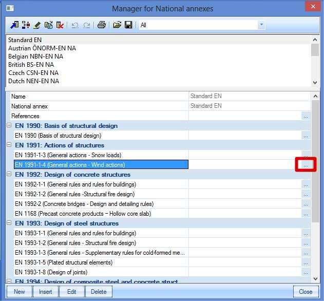
32 Topic Training Load generators In this example, the Cpe,10 values are used. The choice to use the Cpe,10 or the Cpe,1 values, can be made in the National annex parameters. Also the option to take into account the internal pressure coefficients has to be set in these parameters. The national annex parameters can be opened in the project data:

33 2D Wind- and snow generators

34 Topic Training Load generators Snow generator After generating the wind load in both directions, also the snow loads will be generated in this example. For the snow loads, three load cases have to be created. Extra load cases: Snow load 1 (Variable, exclusive) Snow load 2 (Variable, exclusive) Snow load 3 (Variable, exclusive) After creating these load cases, the snow loads can be added in the Load menu with the option Snow generator. By using this snow generator, a frame distance has to be inserted. This has to be done to simulate the wind on a 2D frame as if the wind would be on a complete 3D structure.

35 2D Wind- and snow generators After clicking on OK in this window, the snow load 1 will be generated on the roof elements. The same can be done for Snow load 2 and 3. The Load Coefficients are calculated according to the code, EN Table 5.2 [2] is used for the load coefficients.
 are explained in article 5.3.3 of EN1991-1-3, figure 5.3 [2].")

36 Topic Training Load generators Since the angle α is 11,31 for this example, a load coefficient of 0,80 is used. This is the case for Load mode 1. The different modes (cases) are explained in article of EN , figure 5.3 [2]. So for Snow load 2 and 3, there is a reduction of 50% of the snow weight. Additionally, an accidental design situation can be taken into account. The need to take this into account is National Annex dependent. The different cases are shown in table A.1 of EN [2].
37 2D Wind- and snow generators In Belgium and the Netherlands, the cases B1, B2 and B3 do not need to be considered. Wind & Snow generator This generator is a combination of the wind and snow generator, which are described in the previous chapters. This generator automatically creates: 2 new load groups o o Wind (variable, exclusive) Snow (variable, exclusive) Without over- and underpressure taken into account o 3 new load cases WND L Wind from the left WND R Wind from the right SN Snow loads With over- and underpressure taken into account o 5 new loadcases WND LO Wind from the left - overpressure WND LU Wind from the left - underpressure WND RO Wind from the right - overpressure WND RU Wind from the right - underpressure SN Snow loads By default, the option to use over- and underpressure is grayed out. To be able to use this additional pressure, the option Internal pressure for 2D wind needs to be activated in the National Annex parameters.
38 Topic Training Load generators

. The load panels are of the type To panel edges and beams.")

39 3D Wind Generator 3D Wind Generator In this chapter, the 3D wind generator will be explained. This generator is used to generate the wind loads in all directions according to the code on closed structures. Open the example 3D Wind generator. The structure consists of a steel hall and is closed using load panels. To be able to use the 3D wind generator, the functionality Climatic loads is used with the wind load according to the code (EN ). The load panels are of the type To panel edges and beams. Since these load panels will be used for the distribution of the wind load into line loads on the columns/beams, the option 3D Wind will be marked in the properties of the panels. This means that Wind data will be created on the load panels. This wind data is shown as a small blue arrow. By selecting this arrow, the properties can be viewed and changed. It is necessary that the arrows are pointing in the direction outside the structure. For that reason, there are two Wind Data for which the option Swap outer surface has to be marked. Also the Wind Data for the load panels on the roof should be adapted. By default the Roof type is set to Monopitch. This needs to be changed to Duopitch. Afterwards, the 3D Wind Generator can be used in the load menu. Since there is no load case yet defined, the self weight will be created automatically by opening the Load menu. This window can be closed, to start using the 3D Wind Generator.


![Chapter 2D Wind generator [1]), the Cpi coefficients needs to be inserted manually.](/docs-images/83/87827413/images/40-2.jpg "After clinking on OK, all the load cases that are marked will be created.")
40 Topic Training Load generators Through the button Add Load Cases, it can be chosen which load cases have to be generated. By default, 16 load cases are generated. Four cases for each wind direction. For the Load Coefficients, the Cpe values are taken from the code (EN , see Chapter 2D Wind generator [1]), the Cpi coefficients needs to be inserted manually. After clinking on OK, all the load cases that are marked will be created. These load cases will be gathered in a new automatic created variable load group.


41 3D Wind Generator Afterwards, the generating of the loads in these load cases can be started by using the option Run generator. The loads can be viewed in the Load menu. The loads are generated as surface loads for each zone. By selecting such a surface load, the calculated coefficient can be viewed in the property window: This coefficient is a combination of Cpe and Cpi (see previous chapters). The Cpe and Cpi coefficients can showed graphically by marking this option in the View parameters. All Cpe and Cpi values for each zone and wind direction, can be viewed in the Engineering report

42 Topic Training Load generators
43 Mobile loads Mobile loads The modules needed for the use of mobile loads, are not included in the concept edition. The following modules are needed: - Mobile loads esas.02 (1D members) esas.35 (2D members) - Advanced mobile loads esas.03 (1D members) esas.36 (2D members) Professional edition Expert edition Principle The principle of the module Mobile Loads is based on the theory of the influence lines. An influence line represents a diagram that shows the effect of a unit load on a variable position in a given point of the structure. This is illustrated on the picture below: Figure (a) represents a simple beam on 2 supports, across which a concentrated load P can move. In every section n the moment and the shear force are maximal if the load P is exactly above n. This is shown on figure (b). When the position of the load is changed, similar diagrams can be made. Finally the envelopes can be drawn as shown on figure (c). As expected, the maximal moment appears in the middle of the beam and the extreme shear forces in the supports.
44 Topic Training Load generators Using these influence lines, the effect of more loads on the structures, the so-called load system, can be determined. The goal is to find the position of the load system, for which the effect on the structure in a certain point is maximal. This is illustrated on the following figure. Figure (a) represents a simple beam on two supports again. Across the beam, a system of three point loads can move which represent e.g. the axis loads of a lorry. We look for the position of the load system for which the moment and the shear force are maximal in the section n. The influence line for M n, the moment in n, is shown on figure (b). The moment resulting from the load system can now be determined as follows: M = 3 n P i i= 1 η i
45 Mobile loads At which η i represents the location of the influence line exactly below P i. The maximum of M n is found by trial and error so the sum of the products of an axis load and the influence location below is as large as possible. This maximum is shown on figure (b) at which the moment M n can be determined as follows: M n = Wl[ 0,2(0,12) + 0,8(0,24) + 0,8(0,16) ] = 0, 344Wl For every other position of the load system, a lower maximum in n is obtained. In an analogous way this is illustrated for V n, the shear force at the place of the section n. Figure (c) shows the influence line for the shear force V n. Figures (d) and (e) show the positions of the load system for the maximal positive shear force and the maximal negative shear force. In SCIA Engineer these various steps appear as follows: Input Track across which a Unit load can move Input Unit load Representation Influence lines Input Load system Exploitation in a point at which the Load system is linked to the Unit load Generation load case for exploitation in a point Generation enveloping load cases to gain insight in the global behaviour of the structure. 45
46 Topic Training Load generators Load system Project data For the explanation about the influence lines and the load systems, a new project is created with the following parameters: Code: Eurocode Material: Concrete C25/30 Structure: Frame XZ Project level: advanced To be able to use Mobile loads in a project, this functionality needs to be activated in the Project Data: Construction The construction is built from a Double T bridge girder with the default dimensions given by SCIA Engineer.

47 Mobile loads The construction can be inserted as 3 horizontal beams, at which the begin node is imposed hinged and the other nodes are rolled. To be able to calculate the project, one load case is created, the Self Weight. Input track and unit load In the menu Mobile Loads, a track can be defined from node N1 to N4 with the option Traffic Lane. Afterwards, a unit load can be inserted through the option Unit loads.

48 Topic Training Load generators The option Sections determines the density of the used sections. Use sections from results The unit load is positioned in every section of the beam that lies in the area of the track. The number of sections on a member is indicated in the Solver Setup. Use step according 2D element The unit load is positioned with the step entered of step for 2D element [m]. If an element has a length that is shorter than the adjusted step, it is not loaded by the unit load. Generate at least one section on member Analogously to the previous option; here the unit load is also positioned on elements with a shorter length than the adjusted step. Through the option Generate section under Load system, a section is made under every concentrated load of a load system when showing the results. This way the result can be exactly reviewed under the concentrated load. Influence lines After defining the track and the unit load, the linear calculation can be started. When the calculation is finished, a new group Influence lines appears in the menu Mobile Loads. By looking at the results, there has to be indicated on which member(s) and in which section(s) the results have to be shown by using the Selection Tool.


49 Mobile loads The Preview shows the results numerically, and with the Single Check, the influence line can be shown graphically.

50 Topic Training Load generators Input of load system Through the use of a unit load, the influence lines have been generated. Now this unit load can be linked to a load system. The load systems can be inserted through Load System Database in the Mobile Loads menu. The Load Systems can be inserted manually, or a Load System from the System Database can be chosen: In this example, the load systems will be added manually. Two load systems will be inserted. 1) Single Load System P Loads This load consists of a point load of 150 kn and 2 point loads of 100 kn with a mutual distance of 2m.
51 Mobile loads 2) Single Load System Q Loads This load system consists of a line load of 18 kn/m with an indefinite length.

52 Topic Training Load generators When entering a Single Load system, you have the possibility to mark the option Neglect point load with opposite influence. If this option is activated, the complete concentrated load, which lies in the negative area of the influence line, will be taken in account in the calculation. By activating this option, the found maximum will be reduced. Exploitation of load systems After defining the load systems, the linear calculation can be started. Afterwards, the new group Detail analysis appears in the Mobile Loads menu. With the Detailed Analysis, the load systems can be linked to the unit load. For every desired position on the structure, between all the selected tracks, SCIA Engineer determines the system that is most adverse for the chosen design parameter. An exploitation is performed for the moment My on a position 24m on the first beam B1. The exploitation is performed for the load both the load systems P Load and Q Load. The following option can be adjusted in the Property window for Member force, deformation.

53 Through the action Preview, the results of the required exploitation can be called up: Mobile loads

54 Topic Training Load generators The parts that should be displayed in the report can be indicated through the options Setup report. Under Title 1. It can be seen that the position for which the design parameter My is extreme on a position 24m on member B1. Under Title 6. and 7., is indicated that two extremes have been found.
 on 24m if the reference point of the load system P Load is located at 24m from the begin point of the track.")
55 Mobile loads My is minimal (-622,355 knm) on 24m if the reference point of the load system Q Load is located at 0,000m from the begin point of the track. My is maximal (1134,903 knm) on 24m if the reference point of the load system P Load is located at 24m from the begin point of the track. The values X1 and X2 are the same since a single load system is used. Through the action Single Check the results are shown in a window, at which the position for the exploitation can be simply changed. Generating Load cases Enveloping Load cases Generating Load cases With the exploitation of a design parameter in a section you have the possibility to generate several exclusive variable load cases. First of all the option Load case - generate has to be marked at the Detailed Analysis. If no variable load group is found, the program asks whether a new group has to be made. After activating this option, a Single check is performed on the member B1 through the action Single check.

56 Topic Training Load generators Through the button Generate Load Cases two load cases are generated, one for the minimal My on 24m and one for the maximal My on 24m. The parameter B indicates the member, parameter P the position on the member. Since this option is used to make real load cases, the content of these load cases can be seen. Max My: Min My:
57 Mobile loads After a linear calculation these load cases can be combined with other load cases. Generating Envelope Load cases During the exploitation of the influence line, the individual sections of the track are evaluated for the design components (e.g. My). During this exploitation the critical position of the load system is determined. This position causes a maximal value of the design component in the appropriate section. This value is saved together with the corresponding values of this design component in other sections and the procedure is repeated for the following section. As soon as the calculation is performed for every section, the envelope can be created. Subsequently the system can create envelopes for other design components (e.g. Vy, Vz, etc.). It is important to see that the envelope doesn t represent a realistic load case, so it is not possible to show the content. The envelope represents a fictive load case that shows the found extremes (envelopes). For this reason it is not useful to use this envelope e.g. for a steel check. This envelope can be combined with other load cases to obtain insight in the global behaviour of the structure. To generate the envelope load cases, the option Setup generated load cases in the Mobile Loads menu has to be used.


58 Topic Training Load generators In the window Load case you can enter a name for the load cases you have to make. In this example the names of the load cases are automatically generated by the program by leaving the window blank. With Selection of member the option All members is marked, so all the members are taken into account in the calculation. Through Select Components you can indicate for which components a envelope has to be generated. In this example all components are considered. After importing these data a linear calculation can be performed, so the envelope load cases are made. After the calculation the Load cases manager shows the following:

59 Mobile loads The load cases have Mobile envelope as a description and are in an exclusive load group. In the results menu, the results of these envelope load cases can be reviewed. Max My: Min My: Remarks:
60 Topic Training Load generators When performing a Detailed analysis or generating the enveloping load cases, a number of advanced options is available: Limited run: During the exploitation the critical position of the load system is determined. However, it may happen that the extreme is reached if the mobile load is partially outside the structure. With this option you can indicate whether the mobile load can only appear on a restricted interval of the track so you can avoid that a part of the load system falls partially outside the structure. The restriction of the track will be executed in such a way that the values of the influence lines will be zero outside the given interval. Additional multiplication factor results except deformations: The VOSB code (NEN code) shows that every internal force and reaction for the position of a mobile load has to be multiplied by this coefficient. The results of influence lines for deformations are not multiplied with this factor. It is possible that a deformation of a load case, associated with internal forces such as Max My, has a larger deformation than e.g. the load case Min uz. Additional Mobile factor: The mobile factor is used e.g. to consider a single or double traffic lane. All results are multiplied with this factor, also the deformations. 60

61 Mobile loads Train Loads Approximately the same as in the previous example, can be done with 2D members. In this example, a bridge deck will be modelled as a concrete plate on three line supports. Project Data A new project is created with the following parameters: Code: Eurocode Material: Concrete C25/30 Structure: Plate XZ Project level: advanced To be able to use Mobile loads in a project, this functionality needs to be activated in the Project Data: Construction The bridge deck can be entered as a Plate with thickness 500mm. The length of the bridge deck is 25m, the width is 5m. In the middle of the bridge deck, an internal edge is created with the option Internal Edge. Next the line supports are inserted on the three short edges, with only the translation is the Z-direction prevented.
62 Topic Training Load generators To be able to calculate the project, one load case is created, the Self Weight. Input track and unit load In the Mobile Loads menu, the train track can be inserted. This track consists of two rails with a distance of 1,4m between them. To make sure that the train drives on two rails at the same time, 1 mobile load track is entered with a unit and two impulses on it. The track has to be entered on 1.8m from the edge to be able to place the train track in the middle of the bridge. The coordinates can be entered in the Command line (0;1,8 and 25;1,8) Afterwards, a unit load can be inserted through the option Unit loads.

63 Mobile loads With Sections, the option Use step according 2D element is chosen with 0,25m as step. To have both rails of the train track, a second impulse is added trough the option Add new impulse. The position of the second impulse is 1,4m. Both impulses are displayed on the bridge deck:

64 Topic Training Load generators Influence lines After defining the train track and the unit load that represent both rails, the calculation can be done. To have more accurate results, the mesh is refined in the Mesh Setup. For Average size of 2D element/curved element, a value of 0,5m in inserted. When the calculation is done, a new group Influence lines appears in the Mobile Loads menu. By looking at the results, there has to be indicated on which 2D element and in which point the results have to be shown by using the Selection Tool. The results are asked for the Deformation on slab in the point ( 5 ; 2,5 ; 0 ). The Preview shows the results numerically. The step of 0,25 is clearly shown in this table.


65 Mobile loads Trough the Single Check, the results can be viewed graphically. Input Load systems Through the option Load System Database, a load system can be entered. In this example, a predefined load system is used, namely VOSB 150.

66 Topic Training Load generators Through the option Edit, the properties can be viewed and changed.

67 Mobile loads The load system consists of 2 groups of three point loads and a divided load. The point loads have a value of 150 kn and a mutual distance 1.5m. The divided load has a value of 80 kn/m. The Minimum distance between the load groups is 17m, the Maximum distance is 1000m. SCIA Engineer will let the distances of the load groups between these two boundaries vary to obtain the maximal effect on the bridge deck. The Mobile distributed load between the load groups is 10 kn/m. This value will reduce the found maximum. Exploitation of the load systems After defining the mobile Unit load and the load systems, the linear calculation can be started. After the calculation, a new group appears in the Mobile Loads menu, namely Detail analysis Member 2D force, deformation. With the Detailed Analysis the load system can be linked to the Unit load. For every desired position on the structure, between all the selected tracks, SCIA Engineer determines the system that is most adverse for the chosen design parameter. E.g. an exploitation is performed for the moment mx. The parameters can be set in the Property window and through Selected 2D members is indicated that results are called up for 2D element S1. The option Load case - generate has to marked at the Detailed Analysis. If no variable load group was found, the program asks if a new group had to be made.
. Under Title 6. and 7.")
68 Topic Training Load generators Next through Single Check, the bridge deck can be indicated. The exploitation is performed e.g. in the point ( 5 ; 0 ; 0 ). Under Title 6. and 7. is indicated that two extremes have been found.

69 Mobile loads mx is minimal (-219,197 knm/m) in point ( 5 ; 0 ; 0 ) if the reference point of the first group of point loads is on 0,75m from the begin point of the track and the reference point of the second group of point loads that is on 17,75m. mx is maximal (837,519 knm/m) in point ( 5 ; 0 ; 0 ) if the reference point of the first group of point loads is on 5,75m from the begin point of the track and the reference point of the second group of point load is on 22,75m. In this example it is clear that the distance between both load groups is always 17m, as set at the VOSB 150 load system. Generate load cases Envelope load cases In this example, the envelope load cases will be generated for the moment mx and the shear force vx. After drawing up the envelopes, a selective exploitation is performed in a point from the bridge deck. Generation Envelope Load Cases The option Setup generated load cases is used.


70 Topic Training Load generators After entering these data, a linear calculation can be performed so the enveloping load cases are created. After the linear calculation, the following load cases are generated: Subsequently the results of these envelopes can be viewed for e.g. the moment mx: Max mx:

71 Mobile loads Min mx: Generation of load cases After setting the envelopes, a selective exploitation is performed for the moment, indicated on position ( 10 ; 2,5 ; 0 ). The option Load case generate had to be marked in the Detail Analysis. After activating this option, a Single Check is performed on the bridge deck and the desired position is set.


72 Topic Training Load generators Through Generate load cases, the load cases are generated. In the Load cases manager, a description can be added to these load cases: After rerunning the linear calculation, the results for these generated load cases can be viewed. Load case Max, mx:

73 Results max mx: Mobile loads
74 Topic Training Load generators References and literature [1] Eurocode 1 Actions on structures Part 1-4: General actions - Wind actions [2] Eurocode 1: Actions on structures Part 1-3: General actions- Snow loads 74
General Information Project management Introduction... 4 Getting Started Input geometry... 7
 Tutorial Shell Tutorial Shell All information in this document is subject to modification without prior notice. No part or this manual may be reproduced, stored in a database or retrieval system or published,
Formation SCIA ESA PT
 Formation SCIA ESA PT General Environment: Options, Setup, Help New Project: Project data Windows/toolbars : - Workspace, Window with Main tree and window for properties - Windows change place / close
Version October 2015 RFEM 5. Spatial Models Calculated acc. to Finite Element Method. Introductory Example
 Version October 2015 Program RFEM 5 Spatial Models Calculated acc. to Finite Element Method Introductory Example All rights, including those of translations, are reserved. No portion of this book may be
Tutorial. Plate Concrete
 Tutorial Plate Concrete Tutorial Frame Steel All information in this document is subject to modification without prior notice. No part or this manual may be reproduced, stored in a database or retrieval
Concrete Plate Concrete Slab (ACI )
") Tutorial Tutorial Concrete Plate Concrete Slab (ACI 318-08) Tutorial Concrete Plate All information in this document is subject to modification without prior notice. No part or this manual may be reproduced,
Tutorial Tutorial Concrete Plate Concrete Slab (ACI 318-08) Tutorial Concrete Plate All information in this document is subject to modification without prior notice. No part or this manual may be reproduced,
RFEM 5. Spatial Models Calculated acc. to Finite Element Method. Dlubal Software GmbH Am Zellweg 2 D Tiefenbach
 Version July 2013 Program RFEM 5 Spatial Models Calculated acc. to Finite Element Method Tutorial All rights, including those of translations, are reserved. No portion of this book may be reproduced mechanically,
Tutorial. Steel frame
 Tutorial Steel frame Tutorial Concrete frame All information in this document is subject to modification without prior notice. No part of this manual may be reproduced, stored in a database or retrieval
Tutorial AISC Steel Frame Building
 Tutorial AISC 360-05 Steel Frame Building Tutorial Frame Steel All information in this document is subject to modification without prior notice. No part or this manual may be reproduced, stored in a database
RSTAB 8. Structural Analysis for General Frameworks. Introductory Example. Dlubal Software GmbH Am Zellweg 2 D Tiefenbach
 Version April 2016 Program RSTAB 8 Structural Analysis for General Frameworks Introductory Example All rights, including those of translations, are reserved. No portion of this book may be reproduced mechanically,
Basic Concept Training
 Basic Concept Training SCIA Engineer 17 Basic Concept Training SCIA Engineer 17 All information in this document is subject to modification without prior notice. No part of this manual may be reproduced,
General Information... 1 Introduction... 2 Getting started Starting a project Project management... 6
 Tutorial Tutorial Steel Hall AISC (AISC Steel 360-10) Hall Tutorial Frame Steel All information in this document is subject to modification without prior notice. No part or this manual may be reproduced,
Advanced Training Parameters
 Advanced Training Parameters All information in this document is subject to modification without prior notice. No part of this manual may be reproduced, stored in a database or retrieval system or published,
FOUNDATION IN OVERCONSOLIDATED CLAY
 1 FOUNDATION IN OVERCONSOLIDATED CLAY In this chapter a first application of PLAXIS 3D is considered, namely the settlement of a foundation in clay. This is the first step in becoming familiar with the
Tutorial. Parametric input
 Tutorial Parametric input Tutorial Parametric Input All information in this document is subject to modification without prior notice. No part or this manual may be reproduced, stored in a database or retrieval
Tutorial. External Application Checks using Excel
 Tutorial External Application Checks using Excel External Application Checks for Excel All information in this document is subject to modification without prior notice. No part or this manual may be reproduced,
Case Study - Vierendeel Frame Part of Chapter 12 from: MacLeod I A (2005) Modern Structural Analysis, ICE Publishing
 Modern Structural Analysis, ICE Publishing") Case Study - Vierendeel Frame Part of Chapter 1 from: MacLeod I A (005) Modern Structural Analysis, ICE Publishing Iain A MacLeod Contents Contents... 1 1.1 Vierendeel frame... 1 1.1.1 General... 1 1.1.
Case Study - Vierendeel Frame Part of Chapter 1 from: MacLeod I A (005) Modern Structural Analysis, ICE Publishing Iain A MacLeod Contents Contents... 1 1.1 Vierendeel frame... 1 1.1.1 General... 1 1.1.
SAFI Sample Projects. Design of a Steel Structure. SAFI Quality Software Inc. 3393, chemin Sainte-Foy Ste-Foy, Quebec, G1X 1S7 Canada
 SAFI Sample Projects Design of a Steel Structure SAFI Quality Software Inc. 3393, chemin Sainte-Foy Ste-Foy, Quebec, G1X 1S7 Canada Contact: Rachik Elmaraghy, P.Eng., M.A.Sc. Tel.: 1-418-654-9454 1-800-810-9454
Manual. 3D Wind-Load Generator
 Manual 3D Wind-Load Generator Table of contents Introduction...3 Project settings...4 Definition of the outer surface of the building...6 Generation and editing of zones...7 Zones... 7 Zones editor...
TABLE OF CONTENTS WHAT IS ADVANCE DESIGN? INSTALLING ADVANCE DESIGN... 8 System requirements... 8 Advance Design installation...
 Starting Guide 2019 TABLE OF CONTENTS INTRODUCTION... 5 Welcome to Advance Design... 5 About this guide... 6 Where to find information?... 6 Contacting technical support... 6 WHAT IS ADVANCE DESIGN?...
Scia Engineer Optimizer
 Scia Engineer Optimizer Tutorial All information in this document is subject to modification without prior notice. No part or this manual may be reproduced, stored in a database or retrieval system or
Advanced Professional Training
 Advanced Professional Training Non Linea rand Stability All information in this document is subject to modification without prior notice. No part of this manual may be reproduced, stored in a database
Advance Design. Tutorial
 TUTORIAL 2018 Advance Design Tutorial Table of Contents About this tutorial... 1 How to use this guide... 3 Lesson 1: Preparing and organizing your model... 4 Step 1: Start Advance Design... 5 Step 2:
Tekla Structures Analysis Guide. Product version 21.0 March Tekla Corporation
 Tekla Structures Analysis Guide Product version 21.0 March 2015 2015 Tekla Corporation Contents 1 Getting started with analysis... 7 1.1 What is an analysis model... 7 Analysis model objects...9 1.2 About
Lateral Loading of Suction Pile in 3D
 Lateral Loading of Suction Pile in 3D Buoy Chain Sea Bed Suction Pile Integrated Solver Optimized for the next generation 64-bit platform Finite Element Solutions for Geotechnical Engineering 00 Overview
SETTLEMENT OF A CIRCULAR FOOTING ON SAND
 1 SETTLEMENT OF A CIRCULAR FOOTING ON SAND In this chapter a first application is considered, namely the settlement of a circular foundation footing on sand. This is the first step in becoming familiar
Trademarks. Copyright 2018 by StruSoft. All rights reserved.
 StruSoft AB Fridhemsvägen 22 SE-217 74, Malmö, Sweden www.strusoft.com Version: June 28th, 2018 Copyright 2018 by StruSoft. All rights reserved. Content of this publication may not be reproduced or transmitted
StruSoft StruXML Revit Add-In Manual: Using Revit FEM-Design link
 StruSoft StruXML Revit Add-In Manual: Using Revit FEM-Design link StruSoft AB Fridhemsvägen 22 SE-217 74, Malmö, Sweden www.strusoft.com Version: January 4th, 2017 Copyright Copyright 2017 by StruSoft.
Revised Iain A MacLeod
 LUSAS User Guidelines Revised 20.06.14 Iain A MacLeod Contents 1 Geometrical features and meshes... 1 2 Toolbars... 1 3 Inserting points... 1 4 Inserting a line between two points... 1 5 Creating a dataset...
PLAXIS 2D - SUBMERGED CONSTRUCTION OF AN EXCAVATION
 PLAXIS 2D - SUBMERGED CONSTRUCTION OF AN EXCAVATION 3 SUBMERGED CONSTRUCTION OF AN EXCAVATION This tutorial illustrates the use of PLAXIS for the analysis of submerged construction of an excavation. Most
SUBMERGED CONSTRUCTION OF AN EXCAVATION
 2 SUBMERGED CONSTRUCTION OF AN EXCAVATION This tutorial illustrates the use of PLAXIS for the analysis of submerged construction of an excavation. Most of the program features that were used in Tutorial
StruSoft StruXML Revit Add-In Manual: Using Revit FEM-Design link
 StruSoft StruXML Revit Add-In Manual: Using Revit FEM-Design link StruSoft AB Fridhemsvägen 22 SE-217 74, Malmö, Sweden www.strusoft.com Version: June 19th, 2017 Copyright Copyright 2017 by StruSoft. All
SCIA stands for scientific analyser. The C in SCIA Engineering is not pronounced. Note that the first c in science is not pronounced either.
 Design of a reinforced concrete 4-hypar shell with edge beams P.C.J. Hoogenboom, 22 May 2016 SCIA stands for scientific analyser. The C in SCIA Engineering is not pronounced. Note that the first c in science
Tutorial End+continue in commands. How to use End+continue for different types of commands
 Tutorial End+continue in commands How to use End+continue for different types of commands 1 Release: Scia Engineer 2011 The information contained in this document is subject to modification without prior
Start AxisVM by double-clicking the AxisVM icon in the AxisVM folder, found on the Desktop, or in the Start, Programs Menu.
 1. BEAM MODEL Start New Start AxisVM by double-clicking the AxisVM icon in the AxisVM folder, found on the Desktop, or in the Start, Programs Menu. Create a new model with the New Icon. In the dialogue
CE Advanced Structural Analysis. Lab 4 SAP2000 Plane Elasticity
 Department of Civil & Geological Engineering COLLEGE OF ENGINEERING CE 463.3 Advanced Structural Analysis Lab 4 SAP2000 Plane Elasticity February 27 th, 2013 T.A: Ouafi Saha Professor: M. Boulfiza 1. Rectangular
3 SETTLEMENT OF A CIRCULAR FOOTING ON SAND (LESSON 1) Figure 3.1 Geometry of a circular footing on a sand layer
 Figure 3.1 Geometry of a circular footing on a sand layer") SETTLEMENT OF A CIRCULAR FOOTING ON SAND (LESSON 1) 3 SETTLEMENT OF A CIRCULAR FOOTING ON SAND (LESSON 1) In the previous chapter some general aspects and basic features of the PLAXIS program were presented.
SETTLEMENT OF A CIRCULAR FOOTING ON SAND (LESSON 1) 3 SETTLEMENT OF A CIRCULAR FOOTING ON SAND (LESSON 1) In the previous chapter some general aspects and basic features of the PLAXIS program were presented.
Revised Iain A MacLeod
 LUSAS User Guidelines Revised 01.07.15 Iain A MacLeod Contents 1 Geometrical features and meshes... 1 2 Toolbars... 2 3 Inserting points... 2 4 Inserting a line between two points... 2 5 Creating a dataset...
Step by Step. Tutorial for AxisVM X4. Edited by: Inter-CAD Kft.
 Step by Step Tutorial for AxisVM X4 Edited by: Inter-CAD Kft. 2018 Inter-CAD Kft. All rights reserved All brand and product names are trademarks or registered trademarks. Intentionally blank page Step
ATENA Program Documentation Part 4-2. Tutorial for Program ATENA 3D. Written by: Jan Červenka, Zdenka Procházková, Tereza Sajdlová
 Červenka Consulting s.ro. Na Hrebenkach 55 150 00 Prague Czech Republic Phone: +420 220 610 018 E-mail: cervenka@cervenka.cz Web: http://www.cervenka.cz ATENA Program Documentation Part 4-2 Tutorial for
DRY EXCAVATION USING A TIE BACK WALL
 3 This example involves the dry construction of an excavation. The excavation is supported by concrete diaphragm walls. The walls are tied back by prestressed ground anchors. Silt Sand 10 m 2 m 20 m 10
This document gives a detailed summary of the new features and improvements of FEM- Design version 16.
 This document gives a detailed summary of the new features and improvements of FEM- Design version 16. We hope you will enjoy using the program and its new tools and possibilities. We wish you success.
Bridge Design using the STAAD.Pro/Beava AASHTO Code
 Bridge Design using the STAAD.Pro/Beava AASHTO Code By IEG Group, Bentley Systems Bentley Systems Inc. March 12, 2008 TABLE OF CONTENTS 1.0 Introduction.1 2.0 Creating the Bridge Geometry/Structural Analysis
Advanced training Revit Structure Interface
 Advanced training Revit Structure Interface Revit Structure Interface All information in this document is subject to modification without prior notice. No part or this manual may be reproduced, stored
ANSYS AIM Tutorial Structural Analysis of a Plate with Hole
 ANSYS AIM Tutorial Structural Analysis of a Plate with Hole Author(s): Sebastian Vecchi, ANSYS Created using ANSYS AIM 18.1 Problem Specification Pre-Analysis & Start Up Analytical vs. Numerical Approaches
Tutorial 1: Welded Frame - Problem Description
 Tutorial 1: Welded Frame - Problem Description Introduction In this first tutorial, we will analyse a simple frame: firstly as a welded frame, and secondly as a pin jointed truss. In each case, we will
Advanced 3-D Tutorial
 Advanced 3-D Tutorial Introduction To demonstrate some of the features of VisualAnalysis we have put together this advanced tutorial for you to use. This tutorial assumes that you have a basic knowledge
Settlement of a circular silo foundation
 Engineering manual No. 22 Updated: 02/2018 Settlement of a circular silo foundation Program: FEM File: Demo_manual_22.gmk The objective of this manual is to describe the solution to a circular silo foundation
What's New Advance Design 2016
 What's New Advance Design 2016 Table of contents WELCOME TO ADVANCE DESIGN 2016... 5 NEW RIBBONS... 7 LOCALIZATION: NATIONAL EUROCODE APPENDIXES FOR POLAND... 9 PN-EN 1990:2004/NA:2010 Actions & Combinations...
How to re-open the black box in the structural design of complex geometries
 Structures and Architecture Cruz (Ed) 2016 Taylor & Francis Group, London, ISBN 978-1-138-02651-3 How to re-open the black box in the structural design of complex geometries K. Verbeeck Partner Ney & Partners,
Oasys GSA. Getting Started
 Getting Started 13 Fitzroy Street London W1T 4BQ Telephone: +44 (0) 20 7755 3302 Facsimile: +44 (0) 20 7755 3720 Central Square Forth Street Newcastle Upon Tyne NE1 3PL Telephone: +44 (0) 191 238 7559
WP1 NUMERICAL BENCHMARK INVESTIGATION
 WP1 NUMERICAL BENCHMARK INVESTIGATION 1 Table of contents 1 Introduction... 3 2 1 st example: beam under pure bending... 3 2.1 Definition of load application and boundary conditions... 4 2.2 Definition
INTRODUCTION. Strusoft, the developers. Legend. Pay attention / Note. Useful hint. Example. Clicking left mouse button. Clicking right mouse button
 INTRODUCTION This document gives a detailed summary of the new features and modifications of FEM-Design version 11.0. We hope you will enjoy using the program and its new tools and possibilities. We wish
PHASED EXCAVATION OF A SHIELD TUNNEL
 5 PHASED EXCAVATION OF A SHIELD TUNNEL The lining of a shield tunnel is often constructed using prefabricated concrete ring segments, which are bolted together within the tunnel boring machine to form
1. GENERAL SYSTEM CHANGES. 2. GRILLAGE TEMPLATES - Skewed Grillages Type 2, 3
 ACES V7.0 MAJOR NEW FEATURES 1. GENERAL SYSTEM CHANGES WINDOWS 7: The program has been compiled to run under the WINDOWS 7 Professional (64 Bit) operating system. However, the same version will also run
Contents CHAPTER 2 MODELING
 Contents I. THE NEW UPGRADED INTERFACE of SCADA Pro 3 II. DETAILED DESCRIPTION OF THE NEW INTERFACE 4 1. Modeling 4 1.1 Columns 4 1.2 Beams 8 1.3 Foundation 11 1.4 Surface Elements 14 1.5 Elements 36 1.6
Quick Start Guide. Delivered by. Support: Training:
 Quick Start Guide For support and training on the full range of CSC products, please contact Support: support@cscworld.com Training: training@cscworld.com Delivered by Contents 1.0 Introducing Solve...
Tutorial 4 Arch Bridge
 Tutorial 4 Arch Bridge Civil TUTORIAL 4. ARCH BRIDGE Summary 1 Analysis Model and Load Cases / 2 File Opening and Preferences Setting 5 Enter Material and Section Properties 6 Structural Modeling Using
SDC Verifier is a powerful postprocessor program with an advanced calculation core which works seamlessly with Siemens multi-solver, FEA software
 SDC Verifier is a powerful postprocessor program with an advanced calculation core which works seamlessly with Siemens multi-solver, FEA software suite Simcenter 3D. SDC Verifier & Simcenter 3D SDC Verifier
Torsional-lateral buckling large displacement analysis with a simple beam using Abaqus 6.10
 Torsional-lateral buckling large displacement analysis with a simple beam using Abaqus 6.10 This document contains an Abaqus tutorial for performing a buckling analysis using the finite element program
Frame Analysis. Frame Analysis 1
 Frame Analysis 1Introduction... 7 1.1 Generally... 7 2 Program organization... 9 2.1 Main menu... 10 2.1.1 Input geometry... 11 2.1.1.1 File... 12 2.1.1.2 Edit... 13 2.1.1.3 View... 13 2.1.1.4 Input...
Loads Recognition Tools Checks Reports
 Loads Recognition Tools Checks Reports SDC Verifier is a powerful postprocessor program with an advanced calculation core which works seamlessly with Siemens multi-solver, FEA software suite Femap. SDC
Three- Span Continuous Horizontally Curved. Composite Steel TUB Girder Bridge
 Three- Span Continuous Horizontally Curved Composite Steel TUB Girder Bridge WIZARD, ANALYSIS AND DESIGN TUB Girder Curved Contents Bridge Information Material and Section Properties Wizard Modelling Tweaks
Multiframe May 2010 Release Note
 Multiframe 12.02 18 May 2010 Release Note This release note describes the version 12.02 release of Multiframe, Steel Designer and Section Maker. This release will run on Windows XP/2003/Vista/7. Contents
Background CE 342. Why RISA-2D? Availability
 Background CE 342 RISA-2D RISA-2D is a structural analysis program, which can model: Beams, frames, trusses and plates. Any linear elastic structural material. Typical supports, such as pins, rollers and
Revised Sheet Metal Simulation, J.E. Akin, Rice University
 Revised Sheet Metal Simulation, J.E. Akin, Rice University A SolidWorks simulation tutorial is just intended to illustrate where to find various icons that you would need in a real engineering analysis.
2D Tutorial. Project Description: Running VisualAnalysis: Setting Up the Project:
 2D Tutorial Project Description: This project has been set-up to demonstrate the basic features of VisualAnalysis. You will model and analyze the following two-dimensional frame with a curved glue-laminated
Chapter 3 Analysis of Original Steel Post
 Chapter 3. Analysis of original steel post 35 Chapter 3 Analysis of Original Steel Post This type of post is a real functioning structure. It is in service throughout the rail network of Spain as part
EXAMPLE 1. Static Analysis of Cantilever Column (Fixed-Base Column)
") EXAMPLE 1 Static Analysis of Cantilever Column (Fixed-Base Column) Calculate the top displacement, axial force, shear force and bending moment diagrams for the fixed base column described in the figure
EXAMPLE 1 Static Analysis of Cantilever Column (Fixed-Base Column) Calculate the top displacement, axial force, shear force and bending moment diagrams for the fixed base column described in the figure
Pro MECHANICA STRUCTURE WILDFIRE 4. ELEMENTS AND APPLICATIONS Part I. Yves Gagnon, M.A.Sc. Finite Element Analyst & Structural Consultant SDC
 Pro MECHANICA STRUCTURE WILDFIRE 4 ELEMENTS AND APPLICATIONS Part I Yves Gagnon, M.A.Sc. Finite Element Analyst & Structural Consultant SDC PUBLICATIONS Schroff Development Corporation www.schroff.com
NX Tutorial - Centroids and Area Moments of Inertia ENAE 324 Aerospace Structures Spring 2015
 NX will automatically calculate area and mass information about any beam cross section you can think of. This tutorial will show you how to display a section s centroid, principal axes, 2 nd moments of
Results in SCIA Engineer Results on beams, on slabs, Table results
 Results in SCIA Engineer Results on beams, on slabs, Table results Contacts 7 Opening the service Results 8 Selecting the 1D members for display 9 Selection 9 Selection: Advanced 9 Filter 9 Structure 10
User s Manual ❷ Modeling
 User s Manual ❷ Modeling 2 Contents I. THE NEW UPGRADED INTERFACE of SCADA Pro 5 II. DETAILED DESCRIPTION OF THE NEW INTERFACE 6 1. Modeling 6 1.1 Columns 6 1.2 Beams 10 1.3 Foundation 13 1.4 Surface Elements
CE2302 STRUCTURAL ANALYSIS I Important Questions PART B
 CE2302 STRUCTURAL ANALYSIS I Important Questions PART B UNIT I 1. Determine the vertical and horizontal displacement of the joint B in a pin jointed frame shown in fig. 2. The cross sectional area of each
CE Advanced Structural Analysis. Lab 1 Introduction to SAP2000
 Department of Civil & Geological Engineering COLLEGE OF ENGINEERING CE 463.3 Advanced Structural Analysis Lab 1 Introduction to SAP2000 January 09 th, 2013 T.A: Ouafi Saha Professor: M. Boulfiza Objectives:
WinAqua TUTORIAL WinAqua
 WinAqua TUTORIAL WinAqua WinAqua TUTORIAL Copyright SOFiSTiK AG, D-81514 Műnchen, 1990-2002 This documentation is protected by copyright. No part of it may be reproduced, translated or rewritten in any
Revit Structure 3 ETABS Data Exchange
 Revit Structure 3 ETABS Data Exchange Overview This document describes how to exchange Building Information Modeling (BIM) data between Revit Structure 3 and ETABS, a three-dimensional physical object
Non-Linear Analysis of Bolted Flush End-Plate Steel Beam-to-Column Connection Nur Ashikin Latip, Redzuan Abdulla
 Non-Linear Analysis of Bolted Flush End-Plate Steel Beam-to-Column Connection Nur Ashikin Latip, Redzuan Abdulla 1 Faculty of Civil Engineering, Universiti Teknologi Malaysia, Malaysia redzuan@utm.my Keywords:
Embedded Reinforcements
 Embedded Reinforcements Gerd-Jan Schreppers, January 2015 Abstract: This paper explains the concept and application of embedded reinforcements in DIANA. Basic assumptions and definitions, the pre-processing
midas Civil Advanced Webinar Date: February 9th, 2012 Topic: General Use of midas Civil Presenter: Abhishek Das Bridging Your Innovations to Realities
 Advanced Webinar Date: February 9th, 2012 Topic: General Use of midas Civil Presenter: Abhishek Das Contents: Overview Modeling Boundary Conditions Loading Analysis Results Design and Misc. Introduction
The Generate toolbar has convenient tools to create typical structural shapes.
 Frame Analysis Using Multiframe 1. The software is on the computers in the College of Architecture in Programs under the Windows Start menu (see https://wikis.arch.tamu.edu/display/helpdesk/computer+accounts
Q3 Thin-walled Cross Section. FRILO Software GmbH As of 01/03/2017 Version 2/2016
 Q3 Thin-walled Cross Section FRILO Software GmbH www.frilo.com info@frilo.com As of 01/03/2017 Version 2/2016 Q3 Q3 Thin-walled Cross Section Contents Application options 4 Basis of calculation 6 Definition
PLAXIS 3D. Tutorial Manual
 PLAXIS 3D Tutorial Manual 2010 Build 2681 TABLE OF CONTENTS TABLE OF CONTENTS 1 Introduction 5 2 Lesson 1: Foundation in overconsolidated clay 7 2.1 Geometry 7 2.2 Case A: Rigid foundation 8 2.3 Case B:
Revision of the SolidWorks Variable Pressure Simulation Tutorial J.E. Akin, Rice University, Mechanical Engineering. Introduction
 Revision of the SolidWorks Variable Pressure Simulation Tutorial J.E. Akin, Rice University, Mechanical Engineering Introduction A SolidWorks simulation tutorial is just intended to illustrate where to
1. Define the material properties. Activate the Data Entry menu if it s not already visible, and click on Materials.
 CE 533, Fall 2014 Guide for Using RISA3D 1 / 9 Example Structure. The procedure for calculating frequencies and modes shapes of a multidegree of freedom (MDOF) system will be demonstrated using the following
Guidelines for proper use of Plate elements
 Guidelines for proper use of Plate elements In structural analysis using finite element method, the analysis model is created by dividing the entire structure into finite elements. This procedure is known
FREE VIBRATION AND EARTHQUAKE ANALYSIS OF A BUILDING
 14 FREE VIBRATION AND EARTHQUAKE ANALYSIS OF A BUILDING This example demonstrates the natural frequency of a five-storey building when subjected to free vibration and earthquake loading. The building consists
Part 2: PowerFrame Reference Manual
 Part 2: PowerFrame Reference Manual 2006, BuildSoft NV All rights reserved. No part of this document may be reproduced or transmitted in any form or by any means, electronic or manual, for any purpose
Learning Module 8 Shape Optimization
 Learning Module 8 Shape Optimization What is a Learning Module? Title Page Guide A Learning Module (LM) is a structured, concise, and self-sufficient learning resource. An LM provides the learner with
Results in SCIA Engineer Results on beams, on slabs, Table results
 Results in SCIA Engineer Results on beams, on slabs, Table results Contacts 8 Opening the service Results 10 Selecting the 1D members for display 12 Selection 12 Selection: Advanced 12 Filter 12 Structure
Scientific Manual FEM-Design 17.0
 Scientific Manual FEM-Design 17. 1.4.6 Calculations considering diaphragms All of the available calculation in FEM-Design can be performed with diaphragms or without diaphragms if the diaphragms were defined
Finite Element Course ANSYS Mechanical Tutorial Tutorial 4 Plate With a Hole
 Problem Specification Finite Element Course ANSYS Mechanical Tutorial Tutorial 4 Plate With a Hole Consider the classic example of a circular hole in a rectangular plate of constant thickness. The plate
Steel connections design According to EC3. User s Manual
 Steel connections design According to EC3 User s Manual Version 1.0 April 2017 Contents 1 COPYRIGHT... 5 2 DISCLAIMER... 6 3 PRAXIS GENERAL DESCRIPTION... 7 4 BASE PLATE CONNECTION... 10 4.1 Column...
Advanced model of steel joints loaded by internal forces from 3D frame structures
 Advanced model of steel joints loaded by internal forces from 3D frame structures Lubomír Šabatka, IDEA RS s.r.o František Wald, FSv ČVUT Praha Jaromír Kabeláč, Hypatia Solutions s.r.o Drahoslav Kolaja,
General Applications
 Chapter General Applications The general analysis modules can be used to calculate section properties, wind pressures on buildings and evaluate drainage systems of building roofs. General Applications
Tekla StruXML Export. User s Guide to Tekla Structures - FEM-Design Integration
 Tekla StruXML Export User s Guide to Tekla Structures - FEM-Design Integration StruSoft AB www.strusoft.com Version: August 1st, 2018 Copyright Copyright 2018 by StruSoft. All rights reserved. Content
Finite Element Course ANSYS Mechanical Tutorial Tutorial 3 Cantilever Beam
 Problem Specification Finite Element Course ANSYS Mechanical Tutorial Tutorial 3 Cantilever Beam Consider the beam in the figure below. It is clamped on the left side and has a point force of 8kN acting
Manual BS : 2000 steel code check
 Manual BS 5950-1: 2000 steel code check 1 All information in this document is subject to modification without prior notice. No part or this manual may be reproduced, stored in a database or retrieval system
Autodesk Moldflow Insight AMI Analysis Overview Tutorial
 Autodesk Moldflow Insight 2012 AMI Analysis Overview Tutorial Revision 1, 30 March 2012. This document contains Autodesk and third-party software license agreements/notices and/or additional terms and
Parametric 3d wind loading on hemispheric dome structures Parametric 3d wind loading on hemispheric dome structures
 Parametric 3d wind loading on hemispheric dome structures Parametric 3d wind loading on hemispheric dome structures Felipe Tavares da Silva Federal University of Bahia, Brazil Faculty of Architecture felipe.tavares@ufba.br
Calculation of initial pretension for a cable-stayed bridge using Cable Force Tuning function in midas Civil
 Calculation of initial pretension for a cable-stayed bridge using Cable Force Tuning function in midas Civil Revision Date : 2013.05.13 Program Version : Civil2013 v2.1 00. Contents 01. Overview 3 02.