Advances in Pre-Processing
|
|
|
- Roberta Sims
- 5 years ago
- Views:
Transcription

1 Advances in Pre-Processing Laz Foley Confidence by Design Chicago June 14,
2 Outline ANSYS DesignModeler Modeling Improvements ANSYS SpaceClaim Direct Modeler Workbench Integration and Model Preparation ANSYS Meshing Assembly and General Meshing Improvements ANSYS ICEM CFD and ANSYS TGrid 2


3 ANSYS 14.0 Geometry Advances Focus on enhancing your productivity through new features, increased flexibility, efficiency and usability ANSYS DesignModeler Core modeling improvements Application-specific modeling (e.g. IcePak) ANSYS SpaceClaim Direct Modeler Improved Workbench integration Enhanced Model Preparation Interoperability Support for new CAD releases New CAD file readers 3


4 Direct Entity Input for Modeling Operations Direct entity selections are accepted for Extrude, Revolve, Sweep and Skin/Loft operations Named selections and sketches remain supported as valid inputs for greater automation and flexibility 4 Extrude Revolve Sweep
5 More Hot Keys New set of hot keys (short cuts) for frequently repeated operations F3: Apply F4: Cancel F6: Toggle display (shaded+edges/shaded/wireframe) F7: Zoom to Fit Ctrl-A: Select All Ctrl-P: Toggle Point selection filter Ctrl-E: Toggle Edge selection filter Ctrl-F: Toggle Face selection filter Ctrl-B: Toggle Body selection filter Sketching mode only Ctrl-Z: Undo Ctrl-Y: Redo Ctrl-C: Copy Ctrl-X: Cut Ctrl-V: Paste 5


6 Additional Visualization Controls Improved visualization controls for modeling and topology verifications Available through View options or directly from the Toolbar Edge Direction Display Vertex Display 6


7 Additional Usability Enhancements Single/Box selection toggle RMB + LMB combination to easily toggle between the two selection modes Auto Freeze during slicing Slice feature and Slice Material operations are now available for all bodies Both active and frozen Active bodies involved in the slice are changed to frozen state automatically 7 Active Bodies Bodies involved in the slice are changed to a frozen state automatically


8 Improved Named Selection Transfer and Error Handling Improved Named Selection transfer between ANSYS DesignModeler and other ANSYS Workbench applications Improved Error handling Attach failures Share topology failures A new export property inside DesignModeler to control named selection transfer to other workbench applications Improved error handling to provide appropriate error and warnings in case of failures 8


9 Electronics Tool Improvements - 1 Significant improvements in the custom tool to automate model simplification for flow and thermal analysis by IcePak Display of IcePak icons for IcePak bodies in the feature tree Part structure transfer to IcePak Ability to rename multiple bodies in a single step for easy organization 9


10 Electronics Tool Improvements - 2 Support for additional object types Axis aligned annular cylinder Axis aligned conical frustum Axis aligned annular conical frustum Additional object types and extrusion method for more realistic simplification of complex models Support for Polygonal extrusion 10
11 Performance Improvements Example CAD to Meshing/Mechanical Transfer Time (Sec) R14.0 R13.0 % Diff CAD to DM Transfer Time (Sec) DM to Meshing/Mechanical Transfer Time (Sec) R14.0 R13.0 % Diff R14.0 R13.0 % Diff Model Model Model Model Average Improvements CAD to Meshing/Mechanical 16% 11 CAD to DM 32%; DM to Meshing/Mechanical 10%


12 Improved CAD Interoperability Several new readers to provide two types of interfaces for all major CAD systems for improved productivity and flexibility Associative Interfaces Associative, parametric and Bi-directional Readers Native file readers for users without live CAD access Pro/Engineer GAMBIT reader is enhanced to support non ACIS geometry A new DWG Reader for AutoCAD Improved model processing for faster and targeted updates ANSYS DesignModeler 12
 Creo Parametric Creo Elements/Pro Creo Elements/Direct Modeling Inventor 2012 SolidWorks 2011 NX 8.")
13 CAD Interoperability Options New(updated) Geometry Interfaces at R Associative Interfaces (Associative, bidirectional and parametric) Creo Parametric Creo Elements/Pro Creo Elements/Direct Modeling Inventor 2012 SolidWorks 2011 NX 8.0 Solid Edge ST3 (103) Solid Edge ST4 CATIA V5 R21 Teamcenter , 8.3 CAD Readers AutoCAD 2012* Creo Elements/Pro NX 7.5 Inventor 2011 SolidWorks 2011 Catia V5 R20 Catia V4 IGES and STEP Parasolid 24.0 ACIS R21 GAMBIT 2.4 * Requires an AutoCAD installation


14 CAD Configuration Manager Configure to select a Reader or an Associative Interface 14

15 ANSYS SpaceClaim Enhancements Improved Workbench Integration Improved Associativity and data transfer Support for multiple design points Enhanced Model Preparation Tools for Simulation Preview options for Topology Sharing Volume Extract Tool Improvements Additional Selection and Repair Options 15


16 ANSYS SpaceClaim: Improved Integration Improved ANSYS Workbench Integration Improved Associativity and data transfer Support for multiple design points Preview options for Topology Sharing Preview sharing to view topology sharing before transferring the model into Workbench Help detect and fix topology sharing issues before transfer 16


17 ANSYS SpaceClaim: Volume Extract Tool Improvements Progress reporting Options to specify multiple faces as seeds to create more than one volume in a single step Option to preview face selection propagation to detect leaks during volume extraction 17


18 ANSYS SpaceClaim: Improved Selection and Repair Improved Selection and Repair Options More Selection Options Select Parents Select Children ClipView option to isolate and examine selected region Multi-face patch option for fixing missing faces ClipView Without multi-face patch on With multi-face patch on 18
19 ANSYS 14.0 Meshing Advances Focus on enhancing your productivity through new features, increased flexibility, efficiency and usability Rapid Meshing Reduce time spent in CAD and Meshing Improved handling of complicated geometries Extract flow volume during meshing General Improvements in Meshing Process Improved meshing algorithms Improved process and flexibility Improved robustness Improved speed 19
 to extract flow regions from dirty geometry Support for:")

20 Assembly Meshing Assembly meshing is a top-down meshing approach to mesh all parts at 1 time: Use of virtual bodies (material points) to extract flow regions from dirty geometry Support for: Meshing solids from sheet bodies Conformal mesh between parts w/out having multi-body parts Support for overlapping bodies Handling face-edge connectivity Assembly Capping Face Material point 20

21 Assembly Meshing: Characteristics Assembly meshing replaces 13.0 CutCell Meshing at the GUI level Supports both CutCell and Tetrahedral meshes CutCell meshing maintains characteristics from 13.0 High fraction of hex and prismatic cells Supports global size functions, feature capture, tessellation, etc. controls Operates on parts, multi-body parts, etc. with new option to define virtual bodies Patch independent: Eliminates the need for pinch control and VT operations Creates conformal meshes across parts in contact Eliminates the need for multi-body part generation in CAD Ability to create flow volumes from a closed set of bodies (sheet or solid) Eliminates the need for Boolean/Fill operations in CAD 21


22 Assembly Meshing: Flow Volume Extraction 1. Define Coordinate system inside the Fluid Void 2. Insert a Virtual body 3. Assign the proper Coordinate System to the Material Point in the details of the Virtual Body 4. Done #2 #3 22 #1


23 Assembly Meshing: Keep Solid Mesh In the Assembly Meshing panel, you can choose to keep or discard the mesh in all solids Parts can be marked as Fluids/Solids 23

24 Inflation Improvements Speed and Flexibility of inflation: Several improvements to both assembly and part meshing Better quality during stair stepping Better handling of high aspect ratio inflation Improved speed of inflation creation ~30-100% Industrial Example: 68 Million cells, 5 inflation layers Total Mesh Time: R13: 6 hrs 39 mins R14: 3 hrs 38 mins Assembly Meshing Flexibility CutCell: Full support of 2-stage inflation CutCell and inflation in two separate steps Within the working session Tetrahedron: Uses pre-inflation Faster, more layers, and better quality 24


25 Assembly Meshing: Automatic Inflation Also supported for Virtual Bodies Program controlled inflation acts only on Fluid Bodies CutCell + Inflation Tetrahedron + Inflation 25


26 Assembly Meshing: Sharp Angle Tool A special cell cutting algorithm has been developed to properly capture sharp 3D angles Can be used to improve feature capturing in general Insert a Sharp Angle and pick adjacent faces Example: Sharp angles in the Flow volume of drill bit Mesh without Sharp Angle Mesh with Sharp Angle 26


27 Assembly Meshing Leak Handling: Leakage Path Find leaks using material points: Any time you are using material points (for internal flow), and it is leaking to the outside, you can automatically see the leak-path together with the surface mesh There is a small gap between the valve plug and the valve seat 27
 between parts.")


28 Assembly Meshing Leak Handling: Contact (Interface) Regions Using Contacts for Assembly meshing: Workbench has extensive capabilities to detect contact (interfaces) between parts. Until now, that contact information has been of little use to FLUENT users, but that has changed at 14.0 Contacts have several purposes for Assembly Meshing: Closing of small gaps using contact sizing Find thin sections Find Contacts Features at contact pairs are preserved Contacts are also used in Fluid Surface picker helper For example, in this image the circled edges would be removed without contact defined since the feature angle is below the default (40 degrees) 28


29 Assembly Meshing Leak Handling: Closing Leaks up to 1/5 of min size Contact sizing: Three simple steps 1. Insert a Face-Face Contact between the entities that are leaking Face/Face or Face/Edge 2. Drag and drop the contact on top of the Mesh Icon Creates a Contact sizing 3. Adjust Contact sizing Should be bigger than the gap Limited to gaps up to 1/5 of min-size 4. Generate Mesh Pick the face of the valve plug (blue) and the edge of the valve seat (red) #3 #1 #2 29

30 Assembly Meshing: Finding Thin Sections Why locate thin sections (3D bodies)? Avoid Leakage The assembly meshing method produces better quality meshes if thin baffles and fins are well resolved By using the Find Thin Sections tool, these can be found in advance and appropriate sizing can be applied 30
")
31 Assembly Meshing: Fluid Surfaces Creating Fluid Surfaces for Flow Volume meshing Description Pick all faces that make up the wetted surface of the flow volume Applications Mainly used when only flow volume is needed No conjugate heat transfer Advantage Faster Less memory Reduction of leakages Approach Insert Virtual Body Insert Fluid Surface (select faces) 31


32 Assembly Meshing: Fluid Surfaces To manually select all the faces making up all the flow volume is in many assemblies too time consuming To help out with this task, we have added a new picker helper: Extend to Connection! To use this, you need to have proper connections defined Connections are created automatically in WB, so to start with: delete all the old connections! Create New Connections Make sure min-size is properly set! RMB Find Contacts 32

33 Assembly Meshing: Miscellaneous Features Size Function improvements Separate Min size for Curvature and Proximity Less mesh clustering Support for Body of Influence Mesh Unite Fluid or Solid bodies using Mesh Groups Improve quality of the mesh by releasing geometry constraints at interfaces 33

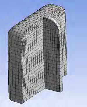
34 Selective Meshing Worksheet For Example: User wants an all hex mesh on quarter piston model Controls order of body meshing: Allows selective body meshing to remain persistent User can record meshing operations, or add steps manually Due to complexity in meshing, user may want to control sequence of meshing steps If recording, steps will be automatically created. 34


35 Selective Meshing Worksheet: Recording Meshing steps relate to Named Selection: When recording, named selections are created for user For example, if recording meshing steps, and user meshes 1 body: 1. Step will be added to Worksheet 2. Named selection will automatically be created 3. Step will not be included in output to solver unless Send to Solver is changed to Yes #2 #3 #1 35

36 Selective Meshing Worksheet: Editing When meshing, if the order in Worksheet needs to be adjusted, this can be done in 1 of several ways: 1. Add, Delete steps 2. Change Contents of Named Selection Note: Add will only append to end of Worksheet, so option #2 is often better. Also, use Active/Inactive options for more flexibility, see following slides 36
 Edit VTs to see VT options Delete Virtual Topology Detail View: Global behavior Statistics view added")
37 Virtual Topologies: Interactive editing Tree view is replaced with graphical selections: Select objects and RMB Operate, or use icon palette to: Merge Edges or Faces Split Edges or Faces Create Hard Vertex Shuffle through VTs (order depicts order of creation) Edit VTs to see VT options Delete Virtual Topology Detail View: Global behavior Statistics view added 37


38 Virtual Topologies Example: Blunt body Flexibility: Allows user to get mapped or swept mesh for nonmappable/non-sweepable bodies 38


39 Virtual Topologies Example: Intersecting Pipes Use Virtual Splits for hex meshing 39

40 Hexahedral Meshing Robustness Improvements: MultiZone, Sweep and Thin Sweep Improved case handling for MultiZone MultiZone improvements: Performance improvements Support for match mesh control All Prisms option 40


41 MultiZone: Robustness Improvements Support for: Handling of cylindrical side faces Imprinting Through bodies Through long stretches of connected side faces Through side faces General improvements Support for edge splits 41


42 MultiZone: Mesh Matching Added Support for Mesh Matching: Cyclic/Periodic Symmetry and/or match mesh control 42

43 MultiZone: Performance Improvements Speed Improvements: Better performance for swept blocks Improved multi-body part handling 14:24 12:00 9:36 7:12 4:48 2:24 0:


44 Tetrahedral Meshing Robustness and Quality improvements in tri surface meshing, inflation and tetrahedral meshing Separated Min Size for Curvature and Proximity Added new option for Advancing Front Triangle Surface Meshing 44

45 Connections for Fluent In 14.0, information in the contact folder will be written as mesh interfaces for Fluent If you have contacts/connections in an old database, the user is asked to remove the contact information A new WB option to NOT generate contacts automatically is available 45

46 Connections for Fluent Start Workbench and open Tools Options Go to Either Meshing or Mechanical Unselect Auto Detect Contact on Attach 46


47 ANSYS ICEM CFD 14.0 Update Productivity enhancements through increased robustness, flexibility, and efficiency Over 200 defects and feature requests resolved User interface Selection and Display Enhancements Model tree enhancements Enhanced Subsets Mesh Editing Enhanced Prism editing, refinement, etc. Output Enhanced output to CGNS, ANSYS FLUENT 47


48 ANSYS ICEM CFD 14.0 Update Enhanced Core Meshing Technology Hexa Blocking Improved interaction Enhanced Create, Split, Move, Link, Smooth, Index control, etc. MultiZone Enhanced Robustness, Sweep, Periodicity, etc. 48


49 ANSYS ICEM CFD Update Enhanced Core Meshing Technology Tetra/Prism TGrid Implementation Refactored New Batch Refinement Tool 49


50 TGrid 14.0 Update Driven by Assembly meshing technology exposed in ANSYS Meshing Assembly Meshing features Material points /mesh/cutcell/set/create-material-points Sharp angle and feature capturing /mesh/cutcell/set/set-thin-cut-faces /mesh/cutcell/set/set-thin-cut-edges Leak path, CutCell-to-Tet conversion, etc. Prism speedup (~2x) Defect fixing Wrapper, CutCell, surface meshing, tet meshing, topology handling, prisms, etc. Updated wrapper templates Contact support for latest version, tutorials 50
 license available The current geometry will be read into TGrid in a faceted format")


51 Interactive TGrid in ANSYS Meshing Interactive TGrid through Assembly meshing (Beta) Beta option enabled and TGrid (or Extended) license available The current geometry will be read into TGrid in a faceted format and Size Function, CutCell Objects, Features and Inflation controls will be transferred to the TGrid session In TGrid the faceted geometries can be checked, SF controls modified, CutCell mesh generated, checked and improved For Tetrahedron, necessary commands to convert CutCell to a tetrahedral mesh are listed in the transcript window Scroll back and cut and paste in the commands Session is returned to ANSYS Meshing upon exit 51
52 Summary ANSYS 14.0 Geometry advances greatly improve productivity through new features, increased flexibility, efficiency and usability ANSYS DesignModeler Core modeling improvements Application-specific modeling ANSYS SpaceClaim Direct Modeler Improved Workbench integration Enhanced Model Preparation Interoperability Support for new CAD releases New CAD file readers 52


53 Summary ANSYS 14.0 Meshing advances greatly improve productivity through new features, increased flexibility, efficiency and usability Rapid Meshing Reduce time spent in CAD and Meshing Improved handling of complicated geometries Extract flow volume during meshing General Improvements in Meshing Process Improved meshing algorithms Improved process and flexibility Improved robustness Improved speed 53
54 Advances in Pre-Processing 54
ANSYS 14.0 Geometry and Meshing Update Steve Varnam ANSYS UK Ltd.
 ANSYS 14.0 Geometry and Meshing Update Steve Varnam ANSYS UK Ltd. 1 ANSYS Workbench Platform The most comprehensive platform for Multiphysics Simulations ANSYS Workbench Framework ANSYS DesignXplorer ANSYS
Automatic & Robust Meshing in Fluids 2011 ANSYS Regional Conferences
 Automatic & Robust Meshing in Fluids 2011 ANSYS Regional Conferences 1 This is just a taste Note that full 14.0 update webinars of an hour per product will be scheduled closer to the release This presentation
Automatic & Robust Meshing in Fluids 2011 ANSYS Regional Conferences
 Automatic & Robust Meshing in Fluids 2011 ANSYS Regional Conferences 1 Automatic & Robust Meshing Assembly Meshing Assembly Meshing enables dramatically reduced time to mesh for typical CAD models by eliminating
Lecture 6: CAD Import Release. Introduction to ANSYS Fluent Meshing
 Lecture 6: CAD Import 14.5 Release Introduction to ANSYS Fluent Meshing 1 Fluent Meshing 14.5 Assembly meshing Workflow This Lecture Tessellated or Conformal CAD import Cap Inlet/Outlets, Create Domains/BOI
Lecture 7: Mesh Quality & Advanced Topics. Introduction to ANSYS Meshing Release ANSYS, Inc. February 12, 2015
 Lecture 7: Mesh Quality & Advanced Topics 15.0 Release Introduction to ANSYS Meshing 1 2015 ANSYS, Inc. February 12, 2015 Overview In this lecture we will learn: Impact of the Mesh Quality on the Solution
Introduction to ANSYS DesignModeler
 Lecture 5 Modeling 14. 5 Release Introduction to ANSYS DesignModeler 2012 ANSYS, Inc. November 20, 2012 1 Release 14.5 Preprocessing Workflow Geometry Creation OR Geometry Import Geometry Operations Meshing
Introduction to ANSYS DesignModeler
 Lecture 7 CAD Connections 14. 5 Release Introduction to ANSYS DesignModeler 2012 ANSYS, Inc. November 20, 2012 1 Release 14.5 CAD Connections What will you learn from this presentation: Geometry Import
Introduction to ANSYS
 Lecture 1 Introduction to ANSYS ICEM CFD 14. 0 Release Introduction to ANSYS ICEM CFD 1 2011 ANSYS, Inc. March 22, 2015 Purpose/Goals Ansys ICEM CFD is a general purpose grid generating program Grids for
Workshop 3: Cutcell Mesh Generation. Introduction to ANSYS Fluent Meshing Release. Release ANSYS, Inc.
 Workshop 3: Cutcell Mesh Generation 14.5 Release Introduction to ANSYS Fluent Meshing 1 2011 ANSYS, Inc. December 21, 2012 I Introduction Workshop Description: CutCell meshing is a general purpose meshing
Introduction to ANSYS ICEM CFD
 Lecture 1 Introduction to ANSYS ICEM CFD 14.5 Release Introduction to ANSYS ICEM CFD 2012 ANSYS, Inc. April 1, 2013 1 Release 14.5 Purpose/Goals Ansys ICEM CFD is a general purpose grid generating program
Introduction to ANSYS FLUENT Meshing
 Workshop 04 CAD Import and Meshing from Conformal Faceting Input 14.5 Release Introduction to ANSYS FLUENT Meshing 2011 ANSYS, Inc. December 21, 2012 1 I Introduction Workshop Description: CAD files will
Best Practices: Volume Meshing Kynan Maley
 Best Practices: Volume Meshing Kynan Maley Volume Meshing Volume meshing is the basic tool that allows the creation of the space discretization needed to solve most of the CAE equations for: CFD Stress
Introduction And Overview ANSYS, Inc. All rights reserved. 1 ANSYS, Inc. Proprietary
 Introduction And Overview 2006 ANSYS, Inc. All rights reserved. 1 ANSYS, Inc. Proprietary The ANSYS Workbench represents more than a general purpose engineering tool. It provides a highly integrated engineering
Introduction to ANSYS Fluent Meshing
 Workshop 06: Mesh Creation Including Removal of Gaps and Baffle Thickness 14.5 Release Introduction to ANSYS Fluent Meshing 1 2011 ANSYS, Inc. December 21, 2012 I Introduction Workshop Description: Fluent
3. MODELING A THREE-PIPE INTERSECTION (3-D)
") 3. MODELING A THREE-PIPE INTERSECTION (3-D) This tutorial employs primitives that is, predefined GAMBIT modeling components and procedures. There are two types of GAMBIT primitives: Geometry Mesh Geometry
3. MODELING A THREE-PIPE INTERSECTION (3-D) This tutorial employs primitives that is, predefined GAMBIT modeling components and procedures. There are two types of GAMBIT primitives: Geometry Mesh Geometry
Manipulating the Boundary Mesh
 Chapter 7. Manipulating the Boundary Mesh The first step in producing an unstructured grid is to define the shape of the domain boundaries. Using a preprocessor (GAMBIT or a third-party CAD package) you
Section 8.3: Examining and Repairing the Input Geometry. Section 8.5: Examining the Cartesian Grid for Leakages
 Chapter 8. Wrapping Boundaries TGrid allows you to create a good quality boundary mesh using a bad quality surface mesh as input. This can be done using the wrapper utility in TGrid. The following sections
Introduction to ANSYS ICEM CFD
 Lecture 4 Volume Meshing 14. 0 Release Introduction to ANSYS ICEM CFD 1 2011 ANSYS, Inc. March 21, 2012 Introduction to Volume Meshing To automatically create 3D elements to fill volumetric domain Generally
Introduction to ANSYS Meshing. Workshop plan
 Lecture 2 Introduction to ANSYS Meshing 2014 W2-1 Schedule WEiP Workshop plan Week 1 - Quick start in ANSYS Week 2 Geometry DesignModeler (DM) Week 3 Mesh Meshing Week 4 Solver FLUENT/CFX Week 5 - Post
GEOMETRY MODELING & GRID GENERATION
 GEOMETRY MODELING & GRID GENERATION Dr.D.Prakash Senior Assistant Professor School of Mechanical Engineering SASTRA University, Thanjavur OBJECTIVE The objectives of this discussion are to relate experiences
Viscous Hybrid Mesh Generation
 Tutorial 4. Viscous Hybrid Mesh Generation Introduction In cases where you want to resolve the boundary layer, it is often more efficient to use prismatic cells in the boundary layer rather than tetrahedral
Workbench Tutorial Minor Losses, Page 1 Tutorial Minor Losses using Pointwise and FLUENT
 Workbench Tutorial Minor Losses, Page 1 Tutorial Minor Losses using Pointwise and FLUENT Introduction This tutorial provides instructions for meshing two internal flows. Pointwise software will be used
Introduction to ANSYS FLUENT Meshing
 Workshop 02 Volume Fill Methods Introduction to ANSYS FLUENT Meshing 1 2011 ANSYS, Inc. December 21, 2012 I Introduction Workshop Description: Mesh files will be read into the Fluent Meshing software ready
TGrid 5.0 Tutorial Guide
 TGrid 5.0 Tutorial Guide April 2008 Copyright c 2008 by ANSYS, Inc. All Rights Reserved. No part of this document may be reproduced or otherwise used in any form without express written permission from
Using the Boundary Wrapper
 Tutorial 7. Using the Boundary Wrapper Introduction Geometries imported from various CAD packages often contain gaps and/or overlaps between surfaces. Repairing such geometries manually is a tedious and
SimLab 14.2 Release Notes
 SimLab 14.2 Release Notes Highlights SimLab 14.2 comes with various changes that improve performance and graphics rendering. In addition to java scripting, python scripting is introduced. The enhancements,
What s New Topics in 3.5.1: 1. User Interface 5. Reference Geometry 2. Display 6. Sketch 3. livetransfer 7. Surface / Solid 4. Scan Tools 8.
 ]^ New Release Turning Measured Points into Solid Models What s New Topics in 3.5.1: 1. User Interface 5. Reference Geometry 2. Display 6. Sketch 3. livetransfer 7. Surface / Solid 4. Scan Tools 8. Measure
SpaceClaim Professional The Natural 3D Design System. Advanced Technology
 SpaceClaim Professional The Natural 3D Design System SpaceClaim Professional is the 3D productivity tool for engineers who contribute to the design and manufacture of mechanical products across a broad
Version 2011 R1 - Router
 GENERAL NC File Output List NC Code Post Processor Selection Printer/Plotter Output Insert Existing Drawing File Input NC Code as Geometry or Tool Paths Input Raster Image Files Convert Raster to Vector
Input CAD Solid Model Assemblies - Split into separate Part Files. DXF, IGES WMF, EMF STL, VDA, Rhino Parasolid, ACIS
 General NC File Output List NC Code Post Processor Selection Printer/Plotter Output Insert Existing Drawing File Input NC Code as Geometry or Tool Paths Input Raster Image Files Report Creator and Designer
Geometry Clean-up in. Numerical Simulations
 Geometry Clean-up in Numerical Simulations Scope of the this Presentation The guidelines are very generic in nature and has been explained with examples. However, the users may need to check their software
Workbench Tutorial Flow Over an Airfoil, Page 1 ANSYS Workbench Tutorial Flow Over an Airfoil
 Workbench Tutorial Flow Over an Airfoil, Page 1 ANSYS Workbench Tutorial Flow Over an Airfoil Authors: Scott Richards, Keith Martin, and John M. Cimbala, Penn State University Latest revision: 17 January
SimLab Release Notes. 1 A l t a i r E n g i n e e r i n g
 SimLab 11.0 Release Notes 1 A l t a i r E n g i n e e r i n g System Support extended to load and save GDA/SLB files of size greater than 4GB. Memory allocation is enhanced to support large models. Kubrix
ANSYS ICEM CFD User's Manual
 ANSYS ICEM CFD User's Manual ANSYS, Inc. Southpointe 2600 ANSYS Drive Canonsburg, PA 15317 ansysinfo@ansys.com http://www.ansys.com (T) 724-746-3304 (F) 724-514-9494 Release 17.0 January 2016 ANSYS, Inc.
Tutorial Week 4 Biomedical Modelling in Ansys Workbench (The Complete Guide with Anatomy and Implant)
") Tutorial Week 4 Biomedical Modelling in Ansys Workbench (The Complete Guide with Anatomy and Implant) Step 1: Create the Anatomical Model in ScanIP Import the DICOM files for the Proximal Femur dataset
Tutorial Week 4 Biomedical Modelling in Ansys Workbench (The Complete Guide with Anatomy and Implant) Step 1: Create the Anatomical Model in ScanIP Import the DICOM files for the Proximal Femur dataset
Feature and Topology Detection
 Feature and Topology Detection Greater possibilities with Capvidia extension and PARTsolutions Cadenas Industry Forum February 5th, 2015 Thomas Tillmann Capvidia GmbH Agenda Company Overview Application
Lesson 3: Surface Creation
 Lesson 3: Surface Creation In this lesson, you will learn how to create surfaces from wireframes. Lesson Contents: Case Study: Surface Creation Design Intent Stages in the Process Choice of Surface Sweeping
Workshop 1: Basic Skills
 Workshop 1: Basic Skills 14.5 Release Introduction to ANSYS Fluent Meshing 2011 ANSYS, Inc. December 21, 2012 1 I Introduction Workshop Description: This workshop shows some of the clean up tools in Tgrid
Finite Element Analysis using ANSYS Mechanical APDL & ANSYS Workbench
 Finite Element Analysis using ANSYS Mechanical APDL & ANSYS Workbench Course Curriculum (Duration: 120 Hrs.) Section I: ANSYS Mechanical APDL Chapter 1: Before you start using ANSYS a. Introduction to
10.1 Overview. Section 10.1: Overview. Section 10.2: Procedure for Generating Prisms. Section 10.3: Prism Meshing Options
 Chapter 10. Generating Prisms This chapter describes the automatic and manual procedure for creating prisms in TGrid. It also discusses the solution to some common problems that you may face while creating
14. AIRPLANE GEOMETRY
 14. AIRPLANE GEOMETRY In this tutorial you will import a STEP file that describes the geometry of an airplane body, including the wing and nacelle that houses the engine. You will clean up the geometry
Hexa Meshing. Defining Surface Parameters for the Mesh Defining Edge Parameters to Adjust the Mesh Checking mesh quality for determinants and angle
 4.2.6: Pipe Blade Overview This tutorial example uses the Collapse function to create a degenerate topology in a Conjugate Heat transfer problem around a blade located in the center of a cylindrical pipe.
Workbench Simulation. Contact Analysis. 1 ANSYS, ANSYS, Inc. Inc. Proprietary
 Workbench Simulation Contact Analysis 1 ANSYS, ANSYS, Inc. Inc. Proprietary Objective and Outline Contact related features available in ANSYS Workbench Contact objects Initial contact status Contact meshing
Autodesk Fusion 360 Training: The Future of Making Things Attendee Guide
 Autodesk Fusion 360 Training: The Future of Making Things Attendee Guide Abstract After completing this workshop, you will have a basic understanding of editing 3D models using Autodesk Fusion 360 TM to
2. MODELING A MIXING ELBOW (2-D)
") MODELING A MIXING ELBOW (2-D) 2. MODELING A MIXING ELBOW (2-D) In this tutorial, you will use GAMBIT to create the geometry for a mixing elbow and then generate a mesh. The mixing elbow configuration is
MODELING A MIXING ELBOW (2-D) 2. MODELING A MIXING ELBOW (2-D) In this tutorial, you will use GAMBIT to create the geometry for a mixing elbow and then generate a mesh. The mixing elbow configuration is
Geometry Definition in the ADINA User Interface (AUI) Daniel Jose Payen, Ph.D. March 7, 2016
 Daniel Jose Payen, Ph.D. March 7, 2016") Geometry Definition in the ADINA User Interface (AUI) Daniel Jose Payen, Ph.D. March 7, 2016 ADINA R&D, Inc., 2016 1 Topics Presented ADINA에서쓰이는 Geometry 종류 Simple (AUI) geometry ADINA-M geometry ADINA-M
Geometry Definition in the ADINA User Interface (AUI) Daniel Jose Payen, Ph.D. March 7, 2016 ADINA R&D, Inc., 2016 1 Topics Presented ADINA에서쓰이는 Geometry 종류 Simple (AUI) geometry ADINA-M geometry ADINA-M
Mesh Generation of Large Size Industrial CFD Applications using a Cartesian Grid based Shrink Wrap approach
 Mesh Generation of Large Size Industrial CFD Applications using a Cartesian Grid based Shrink Wrap approach October 17, 2007 Tetrahedron II Erling Eklund, ANSYS Fluent France Y. K. Lee, ANSYS Inc., Evanston,
Repairing a Boundary Mesh
 Tutorial 1. Repairing a Boundary Mesh Introduction TGrid offers several tools for mesh repair. While there is no right or wrong way to repair a mesh, the goal is to improve the quality of the mesh with
Release Notes. Release Date: March, 2018
 Release Notes Release Date: March, 2018 Software: Geomagic Design X Version 2016.2.1 TABLE OF CONTENTS 1 INTRODUCTION 1 COPYRIGHT 1 2 INSTALLATION 2 SYSTEM REQUIREMENTS 2 DOWNLOAD AND INSTALL SOFTWARE
Lesson 2: Wireframe Creation
 Lesson 2: Wireframe Creation In this lesson you will learn how to create wireframes. Lesson Contents: Case Study: Wireframe Creation Design Intent Stages in the Process Reference Geometry Creation 3D Curve
Structural & Thermal Analysis Using the ANSYS Workbench Release 12.1 Environment
 ANSYS Workbench Tutorial Structural & Thermal Analysis Using the ANSYS Workbench Release 12.1 Environment Kent L. Lawrence Mechanical and Aerospace Engineering University of Texas at Arlington SDC PUBLICATIONS
15. SAILBOAT GEOMETRY
 SAILBOAT GEOMETRY 15. SAILBOAT GEOMETRY In this tutorial you will import a STEP file that describes the geometry of a sailboat hull. You will split the hull along the symmetry plane, create a flow volume
Advanced Meshing Tools
 Page 1 Advanced Meshing Tools Preface Using This Guide More Information Conventions What's New? Getting Started Entering the Advanced Meshing Tools Workbench Defining the Surface Mesh Parameters Setting
ANSA-TGrid: A Common Platform for Automotive CFD Preprocessing. Xingshi Wang, PhD, ANSYS Inc. Mohammad Peyman Davoudabadi, PhD, ANSYS Inc.
 ANSA-TGrid: A Common Platform for Automotive CFD Preprocessing Xingshi Wang, PhD, ANSYS Inc. Mohammad Peyman Davoudabadi, PhD, ANSYS Inc. Overview Motivation Advantages Use Case I: External Aero Dynamic
ANSYS CFD Provides the Best of Both Worlds: Most Accurate Results and Fast Prep and Meshing
 White Paper Fidelity and accuracy are critical in computational fluid dynamics (CFD) simulation. After all, physical prototyping and testing can only be reduced if one can expect accurate simulation results.
CAD Integration ANSYS Drive Canonsburg, PA (T) (F)
 (F)") CAD Integration ANSYS, Inc. Southpointe 2600 ANSYS Drive Canonsburg, PA 15317 ansysinfo@ansys.com http://www.ansys.com (T) 724-746-3304 (F) 724-514-9494 Release 18.2 August 2017 ANSYS, Inc. and ANSYS Europe,
CAD Integration ANSYS, Inc. Southpointe 2600 ANSYS Drive Canonsburg, PA 15317 ansysinfo@ansys.com http://www.ansys.com (T) 724-746-3304 (F) 724-514-9494 Release 18.2 August 2017 ANSYS, Inc. and ANSYS Europe,
ANSYS Workbench Guide
 ANSYS Workbench Guide Introduction This document serves as a step-by-step guide for conducting a Finite Element Analysis (FEA) using ANSYS Workbench. It will cover the use of the simulation package through
Simulation Model Creation and Assembly Essentials. R2014x
 Simulation Model Creation and Assembly Essentials R2014x About this Course Course objectives Upon completion of this course you will be able to: Clean and repair native and imported geometry. Use advanced
SpaceClaim 2009 SP2. Release Notes
 SpaceClaim 2009 SP2 Release Notes Table of contents General... 3 SpaceClaim 2009 SP2 Highlights... 3 Print... 4 Groups... 4 Object, document, component properties... 4 Structure tree... 4 Select... 6 Designing
Introduction to ANSYS DesignModeler
 Lecture 9 Beams and Shells 14. 5 Release Introduction to ANSYS DesignModeler 2012 ANSYS, Inc. November 20, 2012 1 Release 14.5 Beams & Shells The features in the Concept menu are used to create and modify
2008 International ANSYS Conference
 2008 International ANSYS Conference Simulation Driven Product Development using ANSYS Technology Padmesh Mandloi Rahul Kumar Samir Kadam 2008 ANSYS, Inc. All rights reserved. 1 ANSYS, Inc. Proprietary
ANSYS - Workbench Overview. From zero to results. AGH 2014 April, 2014 W0-1
 ANSYS - Workbench Overview From zero to results 2014 W0-1 Runing ANSYS WEiP ANSYS We are going to work in most advanced ANSYS Workbench W0-2 ANSYS Workbench WEiP What is Workbench? Platform for integration
Lecture 3 : General Preprocessing. Introduction to ANSYS Mechanical Release ANSYS, Inc. February 27, 2015
 Lecture 3 : General Preprocessing 16.0 Release Introduction to ANSYS Mechanical 1 2015 ANSYS, Inc. February 27, 2015 Chapter Overview In this chapter we cover basic preprocessing operations that are common
Attila4MC. Software for Simplifying Monte Carlo. For more info contact or
 Attila4MC Software for Simplifying Monte Carlo For more info contact attila@varian.com or Gregory.Failla@varian.com MCNP and MCNP6 are trademarks of Los Alamos National Security, LLC, Los Alamos National
3. Preprocessing of ABAQUS/CAE
 3.1 Create new model database 3. Preprocessing of ABAQUS/CAE A finite element analysis in ABAQUS/CAE starts from create new model database in the toolbar. Then save it with a name user defined. To build
Structured Grid Generation for Turbo Machinery Applications using Topology Templates
 Structured Grid Generation for Turbo Machinery Applications using Topology Templates January 13th 2011 Martin Spel martin.spel@rtech.fr page 1 Agenda: R.Tech activities Grid Generation Techniques Structured
3-D Design Flow Automation for HFSS. Jim DeLap Technical Manager
 3-D Design Flow Automation for HFSS Jim DeLap Technical Manager jim.delap@ansys.com 1 Motivation Existing methods of defining 3D models within HFSS have been sufficient since the introduction of the product
Additional Surface Tools
 Additional Surface Tools Several additional surface tools, techniques, and related functions are available. This supplement provides a brief introduction to those functions. Panel Part Features Replace
2D CAD. Courseware Issued: DURATION: 64 hrs
 2D CAD Introduction File management Orthographic drawings View management Display management Layer management Selection methods Parametric drawings Symbol creation using block BOM / Joinery details creation
Structural & Thermal Analysis using the ANSYS Workbench Release 11.0 Environment. Kent L. Lawrence
 ANSYS Workbench Tutorial Structural & Thermal Analysis using the ANSYS Workbench Release 11.0 Environment Kent L. Lawrence Mechanical and Aerospace Engineering University of Texas at Arlington SDC PUBLICATIONS
Working with Neutral Format Surface and Solid Models in Autodesk Inventor
 Working with Neutral Format Surface and Solid Models in Autodesk Inventor JD Mather Pennsylvania College of Technology Session ID ML205-1P In this class we will learn how to utilize neutral format data
CATIA V5R21 - FACT SHEET
 CATIA V5R21 - FACT SHEET Introduction What s New at a Glance Overview Detailed Description INTRODUCTION CATIA V5 is the leading solution for product success. It addresses all manufacturing organizations;
SimLab 14.3 Release Notes
 SimLab 14.3 Release Notes Highlights SimLab 14.0 introduced new graphical user interface and since then this has evolved continuously in subsequent versions. In addition, many new core features have been
Feature-Based Modeling and Optional Advanced Modeling. ENGR 1182 SolidWorks 05
 Feature-Based Modeling and Optional Advanced Modeling ENGR 1182 SolidWorks 05 Today s Objectives Feature-Based Modeling (comprised of 2 sections as shown below) 1. Breaking it down into features Creating
CATIA V5 Parametric Surface Modeling
 CATIA V5 Parametric Surface Modeling Version 5 Release 16 A- 1 Toolbars in A B A. Wireframe: Create 3D curves / lines/ points/ plane B. Surfaces: Create surfaces C. Operations: Join surfaces, Split & Trim
SpaceClaim 2016 Beta Release Notes. SpaceClaim 2016 Beta. Release Notes
 SpaceClaim 2016 Beta Release Notes Table of Contents Table of Contents... 2 SpaceClaim 2016 Enhancements Overview... 1 Beta Items... 2 Skin Surface... 2 Pull... 19 Move... 22 Split Body... 25 Split...
1. CREATING AND MESHING BASIC GEOMETRY
 1. CREATING AND MESHING BASIC GEOMETRY This tutorial illustrates geometry creation and mesh generation for a simple geometry using GAMBIT. In this tutorial you will learn how to: Start GAMBIT Use the Operation
OVERLAY GRID BASED GEOMETRY CLEANUP
 OVERLAY GRID BASED GEOMETRY CLEANUP Jiangtao Hu, Y. K. Lee, Ted Blacker and Jin Zhu FLUENT INC, 500 Davis St., Suite 600, Evanston, Illinois 60201 ABSTRACT A newly developed system for defining watertight
Solidworks 2006 Surface-modeling
 Solidworks 2006 Surface-modeling (Tutorial 2-Mouse) Surface-modeling Solid-modeling A- 1 Assembly Design Design with a Master Model Surface-modeling Tutorial 2A Import 2D outline drawing into Solidworks2006
Free Convection Cookbook for StarCCM+
 ME 448/548 February 28, 2012 Free Convection Cookbook for StarCCM+ Gerald Recktenwald gerry@me.pdx.edu 1 Overview Figure 1 depicts a two-dimensional fluid domain bounded by a cylinder of diameter D. Inside
CoCreate OneSpace Modeling Data Adapter
 CoCreate OneSpace Modeling 2007 - Data Adapter This document contains the individual datasheets for the native CAD adapters Table of Contents 1. CATIA V4 Data Adapter 2. Unigraphics Data Adapter 3. Pro/ENGINEER
Appendix B: Creating and Analyzing a Simple Model in Abaqus/CAE
 Getting Started with Abaqus: Interactive Edition Appendix B: Creating and Analyzing a Simple Model in Abaqus/CAE The following section is a basic tutorial for the experienced Abaqus user. It leads you
ANSYS AIM 16.0 Overview. AIM Program Management
 1 2015 ANSYS, Inc. September 27, 2015 ANSYS AIM 16.0 Overview AIM Program Management 2 2015 ANSYS, Inc. September 27, 2015 Today s Simulation Challenges Leveraging simulation across engineering organizations
The Quality Of 3D Models
 The Quality Of 3D Models Problems and Solutions for Applications Post-Design Fathi El-Yafi Senior Product Engineer Product Department of EXA Corporation 1 : Overview Status Problems Identified Defect Sources
CATIA Surface Design
 CATIA V5 Training Exercises CATIA Surface Design Version 5 Release 19 September 2008 EDU_CAT_EN_GS1_FX_V5R19 Table of Contents (1/2) Creating Wireframe Geometry: Recap Exercises 4 Creating Wireframe Geometry:
equivalent stress to the yield stess.
 Example 10.2-1 [Ansys Workbench/Thermal Stress and User Defined Result] A 50m long deck sitting on superstructures that sit on top of substructures is modeled by a box shape of size 20 x 5 x 50 m 3. It
Simulation of Turbulent Flow around an Airfoil
 1. Purpose Simulation of Turbulent Flow around an Airfoil ENGR:2510 Mechanics of Fluids and Transfer Processes CFD Lab 2 (ANSYS 17.1; Last Updated: Nov. 7, 2016) By Timur Dogan, Michael Conger, Andrew
SimLab 14.1 Release Notes
 SimLab 14.1 Release Notes Highlights SimLab 14.0 introduced the new user interface. SimLab 14.1 enhances the user interface using feedback from customers. In addition many new core features have been added.
May 11, ANSYS, Inc. All rights reserved. ANSYS, Inc. Proprietary Inventory #
 Chapter 1 ANSYS DesignModeler Introduction to Workbench 1-1 ANSYS Workbench Overview ANSYS Workbench comprises the following modules: Simulation for performing structural and thermal analyses using the
Solving FSI Applications Using ANSYS Mechanical and ANSYS Fluent
 Workshop Transient 1-way FSI Load Mapping using ACT Extension 15. 0 Release Solving FSI Applications Using ANSYS Mechanical and ANSYS Fluent 1 2014 ANSYS, Inc. Workshop Description: This example considers
Workshop 4.2 : Mesh Control
 Workshop 4.2 : Mesh Control 16.0 Release Introduction to ANSYS Mechanical 1 2015 ANSYS, Inc. February 27, 2015 Goals Use the various ANSYS Mechanical mesh controls to enhance the mesh for the model below.
CADdoctor. CADdoctor EX. Product Configuration/Requirements. Product Configuration. Standard Function. Import & Export Options.
 CADdoctor Product Configuration/Requirements Version: EX 8.0 Released date: May 8, 2018 Version: SX 4.2 Released date: July 6, 2017 CADdoctor EX Product Configuration Standard Function Product Import &
PTC CREO. ESSENTIALS PACKAGES Powerful 3D CAD solutions optimized for your product development tasks. PTC Creo Essentials Packages
 PTC CREO PACKAGES Powerful 3D CAD solutions optimized for your product development tasks Product design firms and manufacturing companies are under constant pressure to develop more products in less time,
A Comprehensive Introduction to SolidWorks 2011
 A Comprehensive Introduction to SolidWorks 2011 Godfrey Onwubolu, Ph.D. SDC PUBLICATIONS www.sdcpublications.com Schroff Development Corporation Chapter 2 Geometric Construction Tools Objectives: When
Meshing in STAR-CCM+: Recent Advances Aly Khawaja
 Meshing in STAR-CCM+: Recent Advances Aly Khawaja Outline STAR-CCM+: a complete simulation workflow Emphasis on pre-processing technology Recent advances in surface preparation and meshing Continue to
SolidWorks Implementation Guides. User Interface
 SolidWorks Implementation Guides User Interface Since most 2D CAD and SolidWorks are applications in the Microsoft Windows environment, tool buttons, toolbars, and the general appearance of the windows
3 AXIS STANDARD CAD. BobCAD-CAM Version 28 Training Workbook 3 Axis Standard CAD
 3 AXIS STANDARD CAD This tutorial explains how to create the CAD model for the Mill 3 Axis Standard demonstration file. The design process includes using the Shape Library and other wireframe functions
Best Practices Workshop: Parts & Mesh-Based Operations
 Best Practices Workshop: Parts & Mesh-Based Operations Overview What are Parts and Mesh Based Operations? Transition from Region Based Meshing Why move to Parts Based Meshing How to use Parts Based Mesh
SpaceClaim 2009 SP1. Release Notes
 SpaceClaim 2009 SP1 Release Notes Table of contents General... 4 Licensing... 4 Navigation... 5 Structure tree... 5 Copy and Paste... 6 Select... 6 General selection... 6 Select temporary objects... 7
Abaqus/CAE: Geometry Import and Meshing
 Abaqus/CAE: Geometry Import and Meshing Day 1 Overview of Abaqus/CAE Lecture 1 Demonstration 1 Demonstration 2 Workshop 1 Workshop 2 Workshop 3 Geometry Import and Repair Geometry Import and Repair: Lens