User s Manual Single Board Computer Version 1.0, March 2005
|
|
|
- Jeremy Simpson
- 5 years ago
- Views:
Transcription
1 User s Manual Single Board Computer Version 1.0, March 2005
2 Copyrights This manual is copyrighted and all rights are reserved. It does not allow any non authorization in copied, photocopied, translated or reproduced to any electronic or machine readable form in whole or in part without prior written consent from the manufacturer. In general, the manufacturer will not be liable for any direct, indirect, special, incidental or consequential damages arising from the use of inability to use the product or documentation, even if advised of the possibility of such damages. The manufacturer keeps the rights in the subject to change the contents of this manual without prior notices in order to improve the function design, performance, quality and reliability. The author assumes no responsibility for any errors or omissions, which may appear in this manual, nor does it make a commitment to update the information contained herein. Trademarks Intel is a registered trademark of Intel Corporation. Award is a registered trademark of Award Software, Inc. All other trademarks, products and or product's name mentioned herein are mentioned for identification purposes only, and may be trademarks and/or registered trademarks of their respective companies or owners.
3 Table of Contents Chapter 1 General Information Features Specifications Board Layout Checklist & Mechanical Drawing...9 Chapter 2 Jumper Setting Functions of Jumpers Setting Jumpers Location of Jumpers Jumping Setting Chapter 3 Expansion Capabilities System Memory Installing DIMM Changing CPU Installing Fan Heatsink Appendix: Watchdog Timer Setting...26 Appendix: GPIO User Guide
4 Chapter 1 General Information 4
5 Features. Support socket 604 dual Intel Xeon / LV. Xeon processors with 400/533MHz FSB up to 3.06GHz. Max. 8GB DDR SDRAM support, DDR DIMM x 4 E7501 chipsets. Intel. Intel P64H2 x 1. ATI Rage XL VGA controller w/8mb frame buffer memory 82545EM Gigabit Ethernet control-. Dual Intel lers. Customized 2U heatsink/fan for CPU Specifications System Architecture. Full size SBC with 64bit/66MHz PCI/ISA Golden finger. PCI V2.2 compliant. PICMG 1.0 (Rev.2.0) compliant CPU Support. Socket 604 dual Intel Xeon / LV Xeon processors with 400/533MHz FSB, speed up to 3.06GHz. On board intelligent switching type power regulator x 2. Support streaming SIMD instruction. SMP support is requiring. Support uni-processor implementation.. Support Hyper-Threading technology Main Memory. DDR SDRAM DIMM x4 support max. memory up to 8GB (DDR200/266). Support two 64-bit DDR channels. Registered/ECC DIMMs only BIOS. Award System BIOS. Plug & Play support. Advanced Power Management support. ACPI 2.0 compliant. 4M bits flash ROM Chipsets. Intel E7501 chipsets. Intel ICH3-S (82801CA). Intel P64H2 (82870P2) x1. Intel Firmware Hub (FWH). PCI V2.2 compliant On Board LAN. Dual Intel 82545EM Gigabit Ethernet controllers. Compliant with PCI V2.1/V2.2, IEEE802.3, IEEE 802.3u, IEEE802.3x, IEEE802.3y, IEEE802.3ab. WfM 2.0, PC2001 compliant. RJ45 with LED connector x 2 5
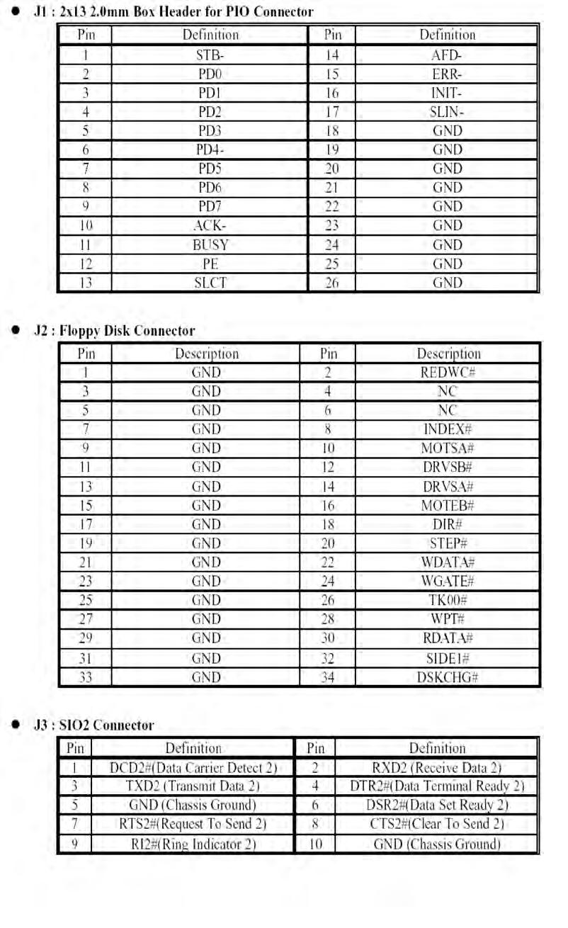
6 On Board VGA. ATI Rage XL with 8MB frame buffer memory. Fully PC 98 and PC 99 Compliant. 15 pin CRT connector x 1 On Chip I/O (ICH3-S). On board USB port x 4. SMBus 2.0 controller. FWH interface. LPC interface. AC interface. PCI 2.2 interface. USB 1.1 compliant. Integrated System Management Controller On Board Super I/O. Onboard ITE 8712F-A super I/O. SIO x 2, with 2 x 16C550 UARTs, 10 pin header x 2. PIOx 1, bi-directional, EPP/ECP support, 26 pin connector x1. Floppy Disk controller: 34 pin connector x 1. 6 pin mini DIN connector x 1, for PS/2 keyboard/mouse, 5 pin connector x 1 (for external keyboard). On Board buzzer x 1. GPIO (4 in 4 out ). On board 2 pin header for I2C;. On Board 2 pin header for reset SW / 2 pin for IDE active LED / 2 pin ATX power SW. One 3 pins power header for 3 pins Power Cable connect to Backplane Board to support ATX Power On function.. On board 4 Pin Additional Power Source Input. AC97 output, 10 pin header x 1 System Monitor. Derived from Super IO ITE 8712F-A to support system monitor.. 8 voltage (For+1.5V, +3.3V, +5V, -5V, +12V, -12V, Vcore and Vcc5VStand-By). One Fan speed for CPU ;Temperature x 2 (one for CPU internal use, another for external system use) ACPI Function ( only when 3 pins Power cable connect to Backplane which connect with ATX Power Source ). Soft Power off. Power-on by Keyboard. Wake-up by LAN. Wake-up by Ring Real Time Clock. On chip RTC with battery back up. External Li Battery x 1 Watchdog Timer. Watchdog timeout can be programmable by Software from 1,2,4,8,16,32, seconds. Reserved 32 bit PCI interface for GAI expansion module. PCI to ISA Bridge & ISAMAX Support. ITE 8888F x 1 PCI to ISA Bridge. Provide 64mA high driving capability to maximize ISA signals for support ISA cards up to 20 on the backplane ISA Slot. Dimensions mm(L) x 122mm(W) 13.3 (L) x 4.8 (W) Customized Heatsink/FAN. Customized heatsink/fan to cover dual processors. Height: 2U 6
7 Power Requirements Voltage Maximum +5V 25A +12V 20A Environments. Operating temperatures: 0 C to 60 C (0 C to 50 C for 2.8GHz CPU). Storage temperatures: -20 C to 80 C. Relative humidity: 10% to 90% (Non-condensing) Certification. CE. FCC 7


8 1.3 Board Layout Max.8GB DDR 266/Dual channel memory in 4 DIMM Slots VGA Port Dual LAN Dual Intel Xeon TM /LV Xeon TM w/533mhz FSB Speed to 3.06GHz+ Intel E7501 Chipset Intel P64H2 64bit PCI-X Bridge Intel 82545EM Gigabit Ethernet Intel ICH3 ATI Rage XL VGA Chipset Figure 1-1: Birdeye s View of
 One 3301470 Quick Reference Guide One 50CM Cable JST 2.")
9 1.4 Checklist After opening the package of the , please check and make sure you have all of the following items: One SBC (A mechanical drawing of this model is shown below.) One Quick Reference Guide One 50CM Cable JST 2.5mm 3 pin to 3 pin (5V standby ATX Power-on Cable) One Y Cable for Keyboard and Mouse One 180 mm AUX Power Cable (for J2) One Cable Set (FDD x1, SIO+PIO x1, SIO x1/keyboard x1/ide66 x1) One USB Cable with Bracket One Driver Manual CD Figure 1-2: Mechanical Drawing of
10 Chapter 2 Jumper & Switch Settings 10
11 This chapter of the User s Manual describes how to set jumpers. Note: The procedures that follow are generic for all of the models Before You Begin Ensure you have a stable, clean working environment. Dust and dirt can get into components and cause a malfunction. Use containers to keep small components separated. Adequate lighting and proper tools can prevent you from accidentally damaging the internal components. Most of the procedures that follow require only a few simple tools, including the following: A Philips screwdriver A flat-tipped screwdriver A set of jewelers Screwdrivers A grounding strap An anti-static pad Using your fingers can disconnect most of the connections. It is recommended that you do not use needlenosed pliers to disconnect connections as these can damage the soft metal or plastic parts of the connectors. Before working on internal components, make sure that the power is off. Ground yourself before touching any internal components, by touching a metal object. Static electricity can damage many of the electronic components. Humid environment tend to have less static electricity than dry environments. A grounding strap is warranted whenever danger of static electricity exists. Precautions Computer components and electronic circuit boards can be damaged by discharges of static electricity. Working on the computers that are still connected to a power supply can be extremely dangerous. Follow the guidelines below to avoid damage to your computer or yourself. Always disconnect the unit from the power outlet whenever you are working inside the case. If possible, wear a grounded wrist strap when you are working inside the computer case. Alternatively, discharge any static electricity by touching the bare metal chassis of the unit case, or the bare metal body of any other grounded appliance. Hold electronic circuit boards (such as the board) by the edges only. Do not touch the components on the board unless it is necessary to do so. Don t flex or stress the circuit board. Leave all components inside the static-proof packaging that they shipped with until they are ready for installation. Use correct screws and do not over tighten screws. 11
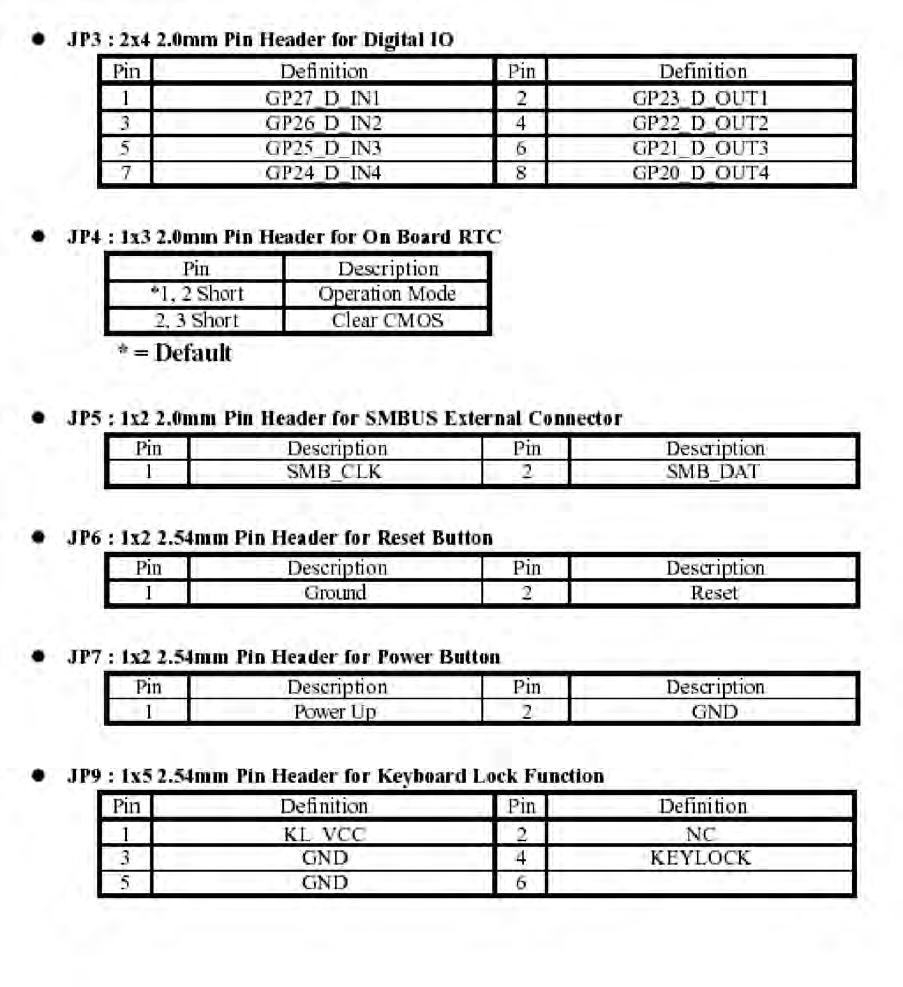
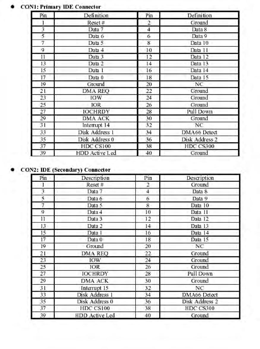
12 2.1 Functions of Jumpers You can use jumpers to set configuration options. The table below defines function of each jumper: Jumper Function Jumper Function J1,J2 Power Connector JP1 Speaker J4,J5 Fan Connector JP3 GPIO J5 on Daughter ATX Power JP4 On-board RTC Board J6 AC 97 JP5 SMBUS J7 IDE Active LED JP6 Reset Button J13 AT/ATX Selection JP7 Power Button JP9 Keyboard Lock Table 2-1: Functions of Jumpers 12


 Short (On) These illustrations show a 3-pin jumper.")
13 2.2 Setting Jumpers A jumper is the simplest kind of electric switch. It consists of two metal pins and a cap. When setting the jumpers, ensure that the jumper caps are placed on the correct pins. When the jumper cap is placed on both pins, the jumper is SHORT. If you remove the jumper cap, or place the jumper cap on just one pin, the jumpr is OPEN. Please see the following illustrations: The illustrations on the right show a 2-pin jumper. When the jumper cap is placed on both pins, the jumper is SHORT. If you remove the jumper cap, or place the jumper cap on just one pin, the jumper is OPEN. Open (Off) Short (On) These illustrations show a 3-pin jumper. Pins 1 and 2 are SHORT. Figure 2-1 : How to Set Jumpers 13
14 2.3 Location of Jumpers The illustration below shows the location of the mainboard jumpers: J1 * J2 * Channel A DIMM 1 Channel B DIMM 2 Channel B DIMM 4 * JP4 Primary CPU Socket Secondary CPU Socket J5 ** J13 ** J6 JP7 JP9 * * JP6 ** 1 SIO JP3 * * * * J7 SIO2 * = P in 1 J5 J4 JP1 JP5 USB Connectors PS/2 KB/Mouse VGA Conn ector LAN Connectors Figure 2-2 : Location of Jumpers 14

15 2.4 Jumper Setting Mainboard 15
16 Daughterboard 16

17 (daughterboard) 17
18 18
19 19
20 Chapter 3 Expansion Capabilities 20
21 3.1 System Memory Your system memory is provided by DIMM s (Dual In-line Memory Modules) on the CPU board. The CPU board contains two memory banks: Bank 0 and 1, corresponding to connector DIMM1, DIMM2. The table below shows possible DIMM configurations for the memory banks. Please be noted that the supports 8 GB DDR SDRAM. Configura- tions using different brands of memory modules are not recommended. DIMM1 Channel A 128MB 256MB 512MB 1024MB Empty Empty Empty Empty 128MB 256MB 512MB 1024MB DIMM3 Channel A DIMM2 Channel B DIMM4 Channel B Total Memory 128MB Empty Empty 256MB 256MB Empty Empty 512MB 512MB Empty Empty 1024MB 1024MB Empty Empty 2048MB Empty 128MB 128MB 256MB Empty 256MB 256MB 512MB Empty 512MB 512MB 1024MB Empty 1024MB 1024MB 2048MB 128MB 128MB 128MB 512MB 256MB 256MB 256MB 1024MB 512MB 512MB 512MB 2048MB 1024MB 1024MB 1024MB 4096MB 2048MB 2048MB 2048MB 2048MB 8192MB Table 3-1 : DIMM Configurations 21


22 3.2 Installing DIMM To install DIMM: 1. Make sure the two handles of the DIMM sockets are in the open position, i.e. the handles stay outward. Figure 3-1 : How to Install DIMM (1) 2. Slowly slide the DIMM modules along the plastic guides in the both ends of the socket. Figure 3-2 : How to Install DIMM (2) 22


23 3. Then press the DIMM module down right into the socket, until a click is heard. That means the two handles automatically locked the memory modules into the right position of the DIMM socket. Figure 3-3 : How to Install DIMM (3) 4. To take away the memory module, just push the both handles outward, the memory module will be ejected by the mechanism in the socket. Figure 3-4 : How to Install DIMM (4) 23

24 3.3 Changing CPU To change the CPU: 1. Pull the handling bar of the socket upward to the other end to loosen the socket s openings. Carefully lift the existing CPU up to remove it from the socket. 2. Place the new CPU on the middle of the socket, orienting its beveled corner to line up with the socket s beveled corner. Make sure the pins of the CPU fit evenly to the socket openings. Replace the handling bar to fasten the CPU to the socket. Figure 3-5 : How to Change CPU 24


25 3.4 Installing the Fan Heatsink Step 1 Insert the fan in the CPU bed. Step 2 As shown in the picture, screw tight. Step 3 Then get the fan connector connected. 25
26 Appendix: Watchdog Timer Setting 1 Watchdog Timer Working Procedure Watchdog Timer (WDT) is a special hardware device that monitors the computer system during normal operation. WDT has a clock circuit that times down from a set number to zero. If a monitored item occurs before the timer reaches zero, WDT resets and counts down again. If for some reason the monitored item doesn t occur before the timer reaches zero, WDT performs an action, such as a diagnostic operation (rebooting the computer). You must enter timer values into WDT Configuration Register (Write the control value to the Configuration Port), and clear WDT counter (read the Configuration Port). WDT Configuration port F2 Default at F2 Watch Dog Timer Disabled 1. Default at disabled Enabled 2. Enabled for user s programming WDT Active Time 1 sec Default at 64 sec 2 sec 4 sec 8 sec 16 sec 32 sec 64 sec 128 sec Table B-1 : Watchdog Timer Character and Function 26
27 2 Watchdog Timer Control Register The Watchdog Timer Control Register controls the WDT working mode. Write the value to the WDT Configuration Port. The following table describes the Control Register bit definition: Table B-2 : WDT Control Register Bit Definition 3 Watchdog Timer Programming Procedure 3.1 Power On or Reset the System The initial value of WDT Control Register (D3~D0) is zero (0), when power is on or the system has been reset. The following table indicates the initial value of WDT ( b ) : Bit Value Mean 3 0 Disable Watchdog Timer 2, 1, Select 64 second Table B-3 : WDT Control Register Initial Value 27
28 B.3.2 Clear the WDT WDT counter interval cannot be longer than the preset time, otherwise, WDT sends a reset signal to the system. The following is an example of clearing the WDT program in Intel 8086 assembly language. ; ( Clear the WDT) Mov dx, F2h ;Setting the WDT configuration port In al, dx Note: Before running WDT, you must clear WDT to ensure that the initial value is zero. B.3.3 WDT Control Register Note: This register writes to WDT configuration port. Set WDT Control Register to control the WDT working mode. The initial value of WDT Control Register is shown as follows: ; (Setting the WDT Control Register as AL) Mov al, 0h ; Setting initial value = 0 for the WDT Control Register Follow these instructions to set the register: 1. Select the time-out intervals of WDT (decide the values of D2, D1, D0 in F2 ) Example: If D2~D0 = 0, the time-out interval is 64 seconds. AND al, b ; Setting the time-out interval as 64 sec. 2. Enable or Disable WDT ( decide D3 value in F2) i.e. D3=0, Disables WDT AND al, b ; Disable the WDT 28
29 i.e. D3=1, Enables WDT OR al, b ; Enable the WDT After finishing the above settings, you must output the Control Register s value to WDT Configuration Port. Then WDT will start according to the above settings. MOV dx, F2h ; Setting WDT Configuration Port OUT dx, al ; Output the Control Register Value 29
30 GPIO User Guide Digital I/O UESD Port 801 I3 I2 I1 I0 O3 O2 O1 O0 { Input }{ Output } JP17 IN 0 IN 1 IN 2 IN OUT 0 OUT 1 OUT 2 OUT 3 30
31 Any advice or comments about our products and service, or anything we can help you with please don t hesitate to contact with us. We will do our best to support your products, projects and business. Address: Global American, Inc. 17 Hampshire Drive Hudson, NH Telephone: Toll Free U.S. Only (800) (603) FAX: (603) Website: Support: Technical Support at Global American
The ROBO-8710VLA package should cover the following basic items
 The ROBO-8710VLA all-in-one full size single board computer is designed to fit high performance and scalable Intel Pentium 4/Celeron processors and compatible for high-end industrial computer system with
ROBO-882N-VG2. User's Manual
 ROBO-882N-VG2 System Host Board User's Manual Copyright Portwell, Inc., 2003. All rights reserved. All other brand names are registered trademarks of their respective owners. Preface Copyright This document
Introduction CHAPTER 1
 CHAPTER 1 Introduction The ROBO-667 all-in-one single board computer is designed to fit a high performance Pentium-III based CPU and compatible for high-end computer system with PCI/ISA Bus architecture.
User s Manual Full-Size PICMG 1.3 SHB Version 1.0
 3308360 User s Manual Full-Size PICMG 1.3 SHB Version 1.0 Copyrights This document is copyrighted and all rights are reserved. It does not allow any non authorization in copied, photocopied, translated
Introduction CHAPTER 1
 CHAPTER 1 Introduction The ACTI-777 all-in-one single board computer is designed to fit a high performance Pentium-III FC-PGA based CPU and compatible for high-end computer system application with PCI/ISA
ACS-2630 Box PC User Manual
 ACS-2630 Box PC User Manual Release Date Revision June 2006 V0.1 2005 Aplex Technology, Inc. All Rights Reserved. Published in Taiwan Aplex Technology, Inc. 9F-5, No. 2, Jian Pa Road, Chung Ho City, Taipei
User s Manual 19 High Speed Panel PCwith one PCI slot, 180W ATX P/S Version 1.0 September 2008
 2907770 User s Manual 19 High Speed Panel PCwith one PCI slot, 180W ATX P/S Version 1.0 September 2008 Copyrights This document is copyrighted and all rights are reserved. It does not allow any non authorization
Introduction CHAPTER 1
 CHAPTER 1 Introduction The ACTI-788 all-in-one single board computer is designed to fit a high performance Celeron based CPU and compatible for high-end computer system application with PCI/ISA bus architecture.
User s Manual Single Board Computer Version A1, June 2007
 User s Manual Single Board Computer 3307900 Version A1, June 2007 Copyrights This manual is copyrighted and all rights are reserved. It does not allow any non authorization in copied, photocopied, translated
PCM-9562 Intel Atom N450/D510 EBX SBC with 3LAN/6 COM/3 SATA/8 USB2.0/2 Watchdog Startup Manual
 PCM-9562 Intel Atom N450/D510 EBX SBC with 3LAN/6 COM/3 SATA/8 USB2.0/2 Watchdog Startup Manual Packing List Before you begin installing your card, please make sure that the following items have been shipped:
PCA-6781 ISA Celeron M Half-sized SBC with VGA/ LCD/LVDS/10/100 Ethernet/USB2.0 and SSD Startup Manual
 PCA-6781 ISA Celeron M Half-sized SBC with VGA/ LCD/LVDS/10/100 Ethernet/USB2.0 and SSD Startup Manual Packing List Specifications Before you begin installing your card, please make sure that the following
PCM-9588 Intel Celeron M EBX SBC with DVI/ TTL/ VGA/ LVDS/ LAN/ 6 COM/ 2 SATA/ 6 USB2.0/16-bit GPIO Startup Manual
 PCM-9588 Intel Celeron M EBX SBC with DVI/ TTL/ VGA/ LVDS/ LAN/ 6 COM/ 2 SATA/ 6 USB2.0/16-bit GPIO Startup Manual Packing List Before you begin installing your card, please make sure that the following
TEOS Hardware System TEOS 8416 / TEOS 1016/ TEOS1216
 TEOS Hardware System TEOS 8416 / TEOS 1016/ TEOS1216 Revision v1.1 November 2011 Copyright 2009~2011 All Rights Reserved Manual Version 1.1 The information contained in this document is subject to change
PTBG965EFN LF. User Manual. English PTBG965EFN LF. Mainboard Manual
 Mainboard Manual 1 Copyright Copyright 2006 FIC (First International Computer) Incorporated All rights reserved. Disclaimer: FIC Inc. shall not be liable for technical or editorial errors or omissions
GS-SR104 Rack Mount Server System Installation Guide
 GS-SR104 Rack Mount Server System Installation Guide 1-i INDEX 1. INTRODUCTION 1-1 1.1. PREFACE 1-1 1.2. FEATURES 1-1 2. HARDWARE INVENTORY 2-1 3. SYSTEM INSTALLATION PROCEDURES 3-1 3.1. CHASSIS COVER
PCM-9584 Onboard Intel Pentium M EBX SBC with Audio, VGA 2LVDS and LAN
 PCM-9584 Onboard Intel Pentium M EBX SBC with Audio, VGA 2LVDS and LAN Packing List Before you begin installing your card, please make sure that the following materials have been shipped: 1 PCM-9584 all-in-one
PCM-4153-A2 PC/104+ SBC w/amd LX800, VGA, LCD, Dual LAN, USB 2.0, On-board Flash and Memory Startup Manual
 PCM--A PC/0+ SBC w/amd LX800, VGA, LCD, Dual LAN, USB.0, On-board Flash and Memory Startup Manual Packing List Specifications Before you begin installing your card, please make sure that the following
LV-681. Mini-ITX motherboard. User s Manual. Edition: /04/09. LV-681 User s Manual 1
 LV-681 Mini-ITX motherboard User s Manual Edition: 1.00 2007/04/09 LV-681 User s Manual 1 Copyright The trademarks mentioned in the manual are legally registered to their respective companies. Disclaimer
PCM-4381 Intel Pentium M EPIC SBC with VGA/2 LVDS/ 2 Ethernet/ 4 COM/ 2 SATA/6 USB 2.0/ 16 bit GPIO
 PCM-4381 Intel Pentium M EPIC SBC with VGA/2 LVDS/ 2 Ethernet/ 4 COM/ 2 SATA/6 USB 2.0/ 16 bit GPIO Before you begin installing your card, please make sure that the following items have been shipped: 1.
PCM-9388 Celeron M 3.5 SBC with PC/104, VGA/ TTL/LVDS Ethernet/USB 2.0 and SSD Startup Manual
 PCM-9388 Celeron M 3.5 SBC with PC/104, VGA/ TTL/LVDS Ethernet/USB 2.0 and SSD Startup Manual Packing List Specifications Before installation, please make sure that you have received the following: 1.
PCM-9386 Celeron M 3.5" SBC with MIO/VGA/LCD/LVDS Ethernet/USB2.0 and SSD
 PCM-9386 Celeron M 3.5" SBC with MIO/VGA/ LCD/LVDS Ethernet/USB2.0 and SSD Startup Manual Packing List Before you begin installing your card, please make sure that the following materials have been shipped:
NuPRO-630. Pentium -II Bus-100MHz VGA
 NuPRO-630 Pentium -II Bus-100MHz VGA Full Size All-in-one PC/104 VGA CRT Interface Supports DMA33 WDT DOC USB IrDA PICMG Bus Industrial Single Board Computer Copyright 1999 All Rights Reserved. Manual
G-MAX TM. ATX Series User s Manual
 Copyright Notice Copyright 2001 Gigabyte Technology. All Rights Reserved. No part of this documentation, including but not limited to the products and software described in it, may be reproduced, transmitted,
System Installation. 3-1 Socket 370 Celeron Processor CHAPTER 3
 CHAPTER 3 System Installation This chapter provides you with instructions to set up your system. The additional information is enclosed to help you install M-system Flash disk, set up LCD display and handle
PCM-9361 Intel Atom N SBC with PC/104, VGA/ TTL/LVDS Ethernet/USB 2.0, SATA and SSD Startup Manual
 PCM-9361 Intel Atom N270 3.5 SBC with PC/104, VGA/ TTL/LVDS Ethernet/USB 2.0, SATA and SSD Startup Manual Packing List Specifications Before you begin installing your card, please make sure that the following
PCM-9363 Intel Atom TM N455/D SBC, DDR3, 24-bit LVDS, CRT or HDMI, 2 Giga LANs, Mini PCIe, 3 COMs Startup Manual
 PCM-9363 Intel Atom TM N455/D525 3.5 SBC, DDR3, 24-bit LVDS, CRT or HDMI, 2 Giga LANs, Mini PCIe, 3 COMs Startup Manual Before you begin installing your card, please make sure that the following items
FWA-6280A User Manual 1. FWA-6280A User Manual
 1 Copyright Notice This document is copyrighted, 2005. All rights are reserved. The original Manufacturer reserves the right to make improvements to the products described in this manual at any time without
Flexible 32-bit PCI to MiniPCI Express Adapter
 About this Document Flexible 32-bit PCI to MiniPCI Express Adapter Hardware Manual June 01, 2011 Revision 1.1 Page 1 About this Document Contents 1 About this Document... 4 1.1 Purpose... 4 1.2 Feedback...
6BMM USER'S MANUAL. 3. Support Modem Ring-On. (Include internal Modem and external modem on COM A and COM B)
") USER'S MANUAL. System power on by PS/2 Mouse: First, enable this function in CMOS Setup, then you can power on the system by double clicking the right or left button of your PS/2 Mouse. 2. System power
USER'S MANUAL. System power on by PS/2 Mouse: First, enable this function in CMOS Setup, then you can power on the system by double clicking the right or left button of your PS/2 Mouse. 2. System power
PCM-9342 EVA-X SBC with PC/104, VGA/ TTL/LVDS Ethernet/USB 2.0 and SSD Startup Manual
 PCM-9342 EVA-X4150 3.5 SBC with PC/104, VGA/ TTL/LVDS Ethernet/USB 2.0 and SSD Startup Manual Packing List Specifications Before you begin installing your card, please make sure that the following items
6SMM7 USER'S MANUAL. Celeron TM Socket 370 Processor MAINBOARD REV. 1.1 First Edition R
 USER'S MANUAL. System power on by Keyboard: If your ATX power supply supports larger than 00 ma 5V Stand-By current (dependent on the specification of keyboards), you can power on your system by entering
Quick Installation Guide
 Quick Installation Guide 2801600 Copyright 2006 All Rights Reserved. The information in this document is subject to change without prior notice in order to improve the reliability, design and function.
CAF-1000 Series Communication Appliance. User s Manual Revision: 1.0
 CAF-1000 Series Communication Appliance User s Manual Revision: 1.0 CE This certificate of conformity of COS-0906 series with actual required safety standards in accordance with 89/366 ECC-EMC Directive
Industrial Computing
 Computing 130 Online service www.nexcom.com -Express 2U 19 Rackmount Platform NSA 2107 1-2 1U 19 Rackmount Platform NSA 1086 1-14 NSA 1046 1-14 1 2 5 3 4 6 7 8 Computing 131 132 133 2 4 5 6 7 8 1 3 Optional
NAR-7060 Communication Appliance
 NAR-7060 Communication Appliance User s Manual Revision: 010 Portwell Inc. 3F, No. 92, Sec. 1, Nei-Hu Rd., Taipei 114, Taiwan, R.O.C. Headquarter: +886-2-2799-2020 FAX: +886-2-2799-1010 http://www.portwell.com.tw
NVR-CV. Network Video Recorder Hot-Swappable Tray for 3.5 HDD x 4 or 2.5 HDD x 4 Gigabit Ethernet x 2 COM x 2, USB2.0 x 6. VGA x 1, DVI-D x 1
 Netw ork Video Recorder N V R - CV Network Video Recorder Hot-Swappable Tray for 3.5 HDD x 4 or 2.5 HDD x 4 Gigabit Ethernet x 2 COM x 2, USB2.0 x 6 VGA x 1, DVI-D x 1 Manual 1st Ed. Oct. 2013 Copyright
VI31 MAINBOARD MANUAL. Date : 1, 2002 PCB : 2.2 (for HP)
") VI31 MAINBOARD MANUAL Date : 1, 2002 PCB : 2.2 (for HP) Table of Contents Table of Contents Chapter 1 Overview The VI31 Mainboard... 1-2 Main Features... 1-3 Chapter 2 Installation Procedures Quick Reference
VI31 MAINBOARD MANUAL Date : 1, 2002 PCB : 2.2 (for HP) Table of Contents Table of Contents Chapter 1 Overview The VI31 Mainboard... 1-2 Main Features... 1-3 Chapter 2 Installation Procedures Quick Reference
LPC-08 Series. Quick Reference Guide. 8 Multi-functional Touch Panel PC. Copyright Notice. 2 nd Ed May 2010
 8 Multi-functional Touch Panel PC Quick Reference Guide 2 nd Ed May 2010 Copyright Notice Copyright 2010 Avalue Technology Inc., ALL RIGHTS RESERVED. Part No. E201708A1A1R Contents 1. Getting Started...3
Colorful Technology Website:
 Colorful Technology Website: http://www.colorful.cn Thanks for purchasing our based on Intel B250 Chipset motherboard. The motherboard C.B250A-BTC PLUS V20 based on Intel B250 Express Chipset, support
Artisan Technology Group is your source for quality new and certified-used/pre-owned equipment
 Artisan Technology Group is your source for quality new and certified-used/pre-owned equipment FAST SHIPPING AND DELIVERY TENS OF THOUSANDS OF IN-STOCK ITEMS EQUIPMENT DEMOS HUNDREDS OF MANUFACTURERS SUPPORTED
F9-3U CompactPCI Pentium M SBC
 F9-3U CompactPCI Pentium M SBC Pentium M (LV) up to 1.8 GHz Celeron M (ULV) 600 MHz 1-slot 32-bit CompactPCI system master PXI system controller 1 GB DDR RAM (SO-DIMM), CompactFlash Graphics controller
PowerBrick-CV User s Manual Edition 2.0
 The Power Brick-CV Users Manual PowerBrick-CV User s Manual Edition 2.0 Small footprint rugged Pentium-M With Digital Video Recorder The Power Brick-CV Users Manual Preface Copyright The material in this
CLK. Slot1 VIA ATX Mainboard. User s Manual 4
 2.1. Mainboard Layout Drawing CLK AGP 1 H14.318 Slot1 VIA693-133 ATX Mainboard ISA2 ISA1 User s Manual 4 2.2. Hardware Installation Steps 2.2.1. Installing System Memory The mainboard is equipped with
Product Specification. Shuttle XPC System J4 4100BA. Economic entry-level Mini-PC. Feature Highlights.
 Economic entry-level Mini-PC The Shuttle XPC J4 4100BA is a Mini-PC with Intel Pentium processor with Socket 775. The new J4 front panel comes with a removable acrylic plate which allows to create individual
EVGA assumes you have purchased all necessary parts needed to allow for proper system functionality.
 Before You Begin Parts NOT in the Kit This kit contains all the hardware necessary to install and connect your new EVGA e-7050/610i GPU motherboard with integrated GeForce graphics processing. However,
iops-18 User Manual 2013 Oct V1 IBASE Technology Inc.
 www.ibase.com.tw iops-18 User Manual 2013 Oct V1 IBASE Technology Inc. iops-18 User Manual 1 Copyright 2013 IBASE Technology Inc. All Rights Reserved. No part of this manual, including the products and
ITA-1711 Series Fanless Compact Embedded IPC with Intel Celeron Dual Core CPU Startup Manual
 ITA-1711 Series Fanless Compact Embedded IPC with Intel Celeron Dual Core CPU Startup Manual Packing List Specifications Before you begin installing your IPC, please make sure that the following items
Industrial Single Board Computer 5.25 Embedded Miniboard
 Industrial Single Board Computer 5.25 Embedded Miniboard LS-573 Support Intel Penryn CPU with DDRIII SO-DIMM, CRT, LVDS, DVI, HDTV, Gigabit LAN, PCI slot, USB, Serial ATAII, Mini PCI, PCI Express mini
DNS User Manual. Version Dec DataON Storage, storage division of Area Data Systems.
 DNS-2670 User Manual Version Dec. 2015 DataON Storage, storage division of Area Data Systems. Contents 1 Introduction... 1 1.1 System Overview... 3 1.1.1 System Top View...3 1.1.2 Front View...4 1.1.3
AMS Series. Fanless System
 AMS100-807 Series Fanless System User s Manual Version 1.0 Table of Contents Chapter 1 Specifications... 3 Chapter 2 AMS100-807 Series Features... 4 Chapter 3 System Dimensions... 5 Chapter 4 Opening the
CPC501. Best solutions to fit your demands! 6U CompactPCI Pentium M SBC.
 6U CompactPCI Pentium M SBC Best solutions to fit your demands! Intel Pentium M processor up to 1.8 GHz High performance and reliability Outstanding communication capabilities Packet switching support
RS-200-RPS-E 2U Rackmount System with Dual Intel
 RS-200-RPS-E 2U Rackmount System with Dual Intel Xeon Processor 3.6 GHz/16 GB DDR2/ 6 SCSI HDDs/Dual Gigabit LAN NEW Features Compact 2U sized rackmount server, front cover with key lock Dual Intel Xeon
Dell Inspiron XPS and Inspiron 9100 Service Manual
 Dell Inspiron XPS and Inspiron 9100 Service Manual Dell Inspiron XPS and Inspiron 9100 Service Manual Before You Begin Memory Module, Mini PCI Card, and Devices System Components Subwoofer Bluetooth Card
Upgrading and Servicing Guide
 Upgrading and Servicing Guide The information in this document is subject to change without notice. Hewlett-Packard Company makes no warranty of any kind with regard to this material, including, but not
PCIE-Q670-R20 Quick Installation Guide Version 2.01
 Full-size PICMG 1.3 CPU Card supports LGA1155 Intel, Intel Core i7/i5/i3/pentium and Celeron processor CPU per Intel Q67, DDR3, VGA /DVI-D, Dual Intel PCIe GbE, SATA 6Gb/s, mini PCIe, HD Audio and RoHS
8806 Series. 15 Multi-functional Touch Panel PC. Quick Reference Guide
 8806 Series 15 Multi-functional Touch Panel PC Quick Reference Guide 1st Ed 10 July, 2009 8806 Contents 1. Getting Started...3 1.1 Safety Precautions...3 1.2 Packing List...3 1.3 System Specifications...4
User s Manual Single Board Computer Version A2, March 2007
 User s Manual Single Board Computer 3307910 Version A2, March 2007 Copyrights This manual is copyrighted and all rights are reserved. It does not allow any non authorization in copied, photocopied, translated
MN525RI MN525MI. User's Manual. Intel D525 Processor Motherboards. Rev. 1001
 MN525RI MN525MI Intel D525 Processor Motherboards User's Manual Rev. 1001 Copyright 2010 GIGA-BYTE TECHNOLOGY CO., LTD. All rights reserved. The trademarks mentioned in this manual are legally registered
1.1.Packing Contents 1*Colorful C.B250A-BTC V20 motherboard 2*SATA cables 1*Driver/Utility CD 1*User's Guide 1*I/O shield 1.2.MOTHERBOARD SPEC CPU
 Colorful Technology Website: http://www.colorful.cn Thanks for purchasing our based on Intel B250 Chipset motherboard. The motherboard C.B250A-BTC V20 based on Intel B250 Express Chipset, support Intel
686BX USER'S MANUAL. 3. Supports 3 steps ACPI LED. 4. Modem Ring-On. (COM B) 5. Wake-Up on LAN. (on J13) 6. Supports LDCM
 5. Wake-Up on LAN. (on J13) 6. Supports LDCM") 686BX USER'S MANUAL. System power on by PS/2 Mouse: First, enable this function in CMOS Setup, then you can power on the system by double clicking the right or left button of your PS/2 Mouse. 2. System
686BX USER'S MANUAL. System power on by PS/2 Mouse: First, enable this function in CMOS Setup, then you can power on the system by double clicking the right or left button of your PS/2 Mouse. 2. System
Chapter 2: Disassembly
 P370EM / P370EM3 Chapter 2: Overview This chapter provides step-by-step instructions for disassembling the P370EM / P370EM3 series notebook s parts and subsystems. When it comes to reassembly, reverse
System Host Boards. Riser Cards. Slot Single Board Computers. Selection Guide
 Riser Cards System s AIMB-RP10P-01A1E AIMB-RP30P-03A1E AIMB-RH31P-12A1E AIMB-RP3PF-21A1E Interface PCI PCI PCIe x1 + PCI PCIe x16 + PCI Expansion slots 1 PCI 3 PCI 1 PCIe x1 + 2 PCI 1 PCIe x16 + 2 PCI
CAD-0205 Series Communication Appliance. User s Manual Revision: 1.4
 CAD-0205 Series Communication Appliance User s Manual Revision: 1.4 CE This certificate of conformity of CAD-0205 series with actual required safety standards in accordance with 89/366 ECC-EMC Directive
PFM-LNP. PC/104 Modules. Features. Specifications. Packing List. PC/104 Module With Intel Atom N450 Processor Intel Atom N450 1.
 PFM-LNP Module With Intel Atom N450 Processor Modules Front Panel LAN LED Keyboard & Mouse Power USB SATA SATA Power COM VGA LVDS Intel Atom N450 1.66 GHz Processor Intel ICH8M Onboard DDR2 667 Memory,
Intel /100Mbps Ethernet Controller 32bit PCI Slot x2. ATI Rage XL Video Chip with 4MB Video RAM onboard 64bit PCI Slot x4
 PS/2 Mouse SPP/ECP/EPP Print Port USB RJ45 LAN JP0 CPU Terminator Jumper PS/2 Keyboard Port VGA BP (Backplane) 2 Port WOL (Wake On LAN) Intel 82559 0/00Mbps Ethernet Controller 32bit PCI Slot x2 ATI Rage
EVO-TP Hardware System
 User Manual Revision v1.3 February 2010 EVO-TP Hardware System Copyright 2009 February All Rights Reserved Manual Version 1.1 Part Number: The information contained in this document is subject to change
TABLE OF CONTENTS 1. INTRODUCTION 2. SPECIFICATION 3. HARDWARE INSTALLATION 6BA
 6BA TABLE OF CONTENTS 1. INTRODUCTION 1.1. PREFACE...1-1 1.2. KEY FEATURES...1-1 1.3. PERFORMANCE LIST...1-2 1.4. BLOCK DIAGRAM...1-3 1.5. INTRODUCE THE Pentium II / III Processor...1-4 1.6. What is AGP?...1-5
AIMB-210 (Intel Atom processor N GHz FSB 533 MHz Mini-ITX Motherboard with VGA, LVDS, TV-Out, 6 COM, Dual GbE, 8 USB, 2 SATA II) Startup Manual
 Startup Manual") AIMB-210 (Intel Atom processor N270 6 GHz FSB 533 MHz Mini-ITX Motherboard with VGA, LVDS, TV-Out, 6 COM, Dual GbE, 8 USB, 2 SATA II) Startup Manual Before you begin installing your card, please make sure
AIMB-210 (Intel Atom processor N270 6 GHz FSB 533 MHz Mini-ITX Motherboard with VGA, LVDS, TV-Out, 6 COM, Dual GbE, 8 USB, 2 SATA II) Startup Manual Before you begin installing your card, please make sure
Upgrading and Servicing Guide
 Upgrading and Servicing Guide The only warranties for Hewlett-Packard products and services are set forth in the express statements accompanying such products and services. Nothing herein should be construed
User s Manual. MMX Enhanced MediaGX System Board. MMX Enhanced MediaGX System Board
 MMX Enhanced MediaGX System Board MMX Enhanced MediaGX System Board Trademarks and / or Registered trademarks are the properties of their respective owners. User s Manual IBM, PC/AT and PC/XT are trademarks
TABLE OF CONTENTS 1. INTRODUCTION 2. SPECIFICATION 3. HARDWARE INSTALLATION 6EX 1.1. PREFACE KEY FEATURES PERFORMANCE LIST...
 6EX TABLE OF CONTENTS 1. INTRODUCTION 1.1. PREFACE...1-1 1.2. KEY FEATURES...1-1 1.3. PERFORMANCE LIST...1-2 1.4. BLOCK DIAGRAM...1-3 1.5. INTRODUCE THE Pentium II Processor & AGP...1-4 1.6 What is AGP?...
FPC 08W Series. 8 Widescreen Multi-functional Touch Panel PC. Quick Reference Guide. 2 nd Ed 28 June, 2010
 FPC 08W Series 8 Widescreen Multi-functional Touch Panel PC Quick Reference Guide 2 nd Ed 28 June, 2010 Copyright Notice Copyright 2010 Avalue Technology Inc., ALL RIGHTS RESERVED. Part No. E201708WAA1R
Disassembly Manual T19
 Disassembly Manual T19 version change by date 0.1 Copied text from written notes DE 18-10-2005 0.2 Added photos & corrected layout DE 19-10-2005 Page 1 of 15 Battery & Dummy Cards 1. Remove the Battery.
Quick Start Guide. SY-6BB V1.0 Mainboard F C. Introduction. Installation. Hardware. Quick BIOS Setup. The SOYO CD
 SY-6BB V.0 Mainboard Quick Start Guide Introduction Hardware Installation Quick BIOS Setup The SOYO CD F C Tested To Comply With FCC Standards FOR HOME OR OFFICE USE POST CONSUMER 00% RECYCLED PAPER SOYO
Upgrading and Servicing Guide
 Upgrading and Servicing Guide The information in this document is subject to change without notice. Hewlett-Packard Company makes no warranty of any kind with regard to this material, including, but not
TABLE OF CONTENTS 1. INTRODUCTION 1.1. PREFACE KEY FEATURES PERFORMANCE LIST BLOCK DIAGRAM...
 TABLE OF CONTENTS 1. INTRODUCTION 1.1. PREFACE... 1-1 1.2. KEY FEATURES... 1-1 1.3. PERFORMANCE LIST... 1-3 1.4. BLOCK DIAGRAM... 1-4 1.5. INTRODUCE THE PCI - BUS... 1-5 1.6. FEATURES... 1-5 2. SPECIFICATION
MPC 21 Series. Quick Reference Guide. 21 Multifunctional Touch Panel PC. 1 st Ed 28 october Part No. E201721W3A1R
 21 Multifunctional Touch Panel PC Quick Reference Guide 1 st Ed 28 october 2010. Part No. E201721W3A1R 1. Getting Started 1.1 Safety Precautions Warning! Always completely disconnect the power cord from
EPC-APL. Quick Reference Guide. Intel Pentium /Celeron Processor Fanless Tiny System. Copyright Notice. 1 st Ed 12 September 2017
 Intel Pentium /Celeron Processor Fanless Tiny System Quick Reference Guide 1 st Ed 12 September 2017 Copyright Notice Copyright 2017 ALL RIGHTS RESERVED. Part No. E2017CAI0A0R FCC Statement THIS DEVICE
Dell Precision M4600 Owner's Manual
 Dell Precision M4600 Owner's Manual Regulatory Model P13F Regulatory Type P13F001 Notes, Cautions, and Warnings NOTE: A NOTE indicates important information that helps you make better use of your computer.
D4-6U CompactPCI Pentium 4 SBC
 D4-6U CompactPCI Pentium 4 SBC Mobile Pentium 4 up to 2.2GHz 1-slot CompactPCI 64-bit/66MHz PXI system controller 1GB DRAM, CompactFlash Graphics controller/digital video output 2 Gigabit Ethernet (front)
EX-96XX6A HMI User Manual
 EX-96XX6A HMI User Manual Release Date Revision Nov 2011 V1.0 2011 All Rights Reserved. Published in Taiwan EX-96XX6A User Manual 1 Warning! This equipment generates, uses and can radiate radio frequency
Compact Board with Onboard Intel Atom N455/D525 Processor. Features USB2.0 COM. Front Panel. Keyboard/ Mouse. Packing List Jumper Cap
 0 PCM-LN02 Compact Board with Onboard Intel Atom N455/D525 Processor Compact Boards Full-size Mini Card PCI Half-size Mini Card ATX LVDS CRT LCD Inverter SATA LPT Ethernet RJ-45 DIO PC/04 + USB2.0 COM
Platform CPU. Chipset Memory. Featuring the Intel P55 Express Chipset. Expansion Slot. Audio LAN. Rear Panel I/O. Connector.
 Detail Specification Platform CPU - Micro ATX Form Factor: 9.6-in x 8.8-in, 24.4 cm x 22.4 cm - All Solid Capacitor design (100% Japan-made high-quality Conductive Polymer Capacitors) - Supports the Intel
TABLE OF CONTENTS 1. INTRODUCTION 2. SPECIFICATION 3. HARDWARE INSTALLATION 6BXDS 1.1. PREFACE KEY FEATURES...1-1
 6BXDS 1. INTRODUCTION TABLE OF CONTENTS 1.1. PREFACE...1-1 1.2. KEY FEATURES...1-1 1.3. PERFORMANCE LIST...1-2 1.4. BLOCK DIAGRAM...1-3 1.5. INTRODUCE THE Pentium II Processor...1-4 1.6. What is AGP?...1-6
F9-3U CompactPCI PentiumM SBC
 F9-3U CompactPCI PentiumM SBC Pentium M (LV) up to 1.8 GHz Celeron M (ULV) 600 MHz 1-slot 32-bit CompactPCI system master 1 GB DDR RAM (SO-DIMM), CompactFlash Graphics controller / DVI-I (front) Gigabit
USER MANUAL VERSION V1.0 AUG MiniPOS Hardware System
 USER MANUAL VERSION V1.0 AUG 2010 MiniPOS Hardware System Copyright 2010 August All Rights Reserved Manual Version 1.0 Part Number: 3LMPPA530110 The information contained in this document is subject to
FCC Information Federal Communications Commission Radio Frequency Interference Statement
 FCC Information Federal Communications Commission Radio Frequency Interference Statement This equipment has been tested and found to comply with the limits for a Class B Digital Device, pursuant to Part
Overview Industrial SBCs / Embedded Controller
 Overview Industrial / Embedded Controller Part number VGA Controller onboard VGA in MB Support for LCD/TFT Front Side Bus in MHz (max.) Disk-on-Chip socket Ethernet onboard in GB (max.) DIMM Modules supp.
TravelMate 6493 Series Disassembly Instruction
 TravelMate 6493 Series Disassembly Instruction please refer to http://csd.acer.com.tw PRINTED IN TAIWAN Chapter 3 Machine Disassembly and Replacement This chapter contains step-by-step procedures on how
Mercury Helios ASSEMBLY MANUAL & USER GUIDE
 Mercury Helios ASSEMBLY MANUAL & USER GUIDE TABLE OF CONTENTS INTRODUCTION...1 1.1 MINIMUM SYSTEM REQUIREMENTS 1.1.1 Apple Mac Requirements 1.1.2 PC Requirements 1.1.3 Supported PCIe Cards NOTE: Boot Camp
Motherboard Specifications, A8AE-LE (AmberineM)
") 1 of 7 6/28/2009 11:14 PM» Return to original page Motherboard Specifications, A8AE-LE (AmberineM) Motherboard specifications table Motherboard layout and photos Clearing the CMOS settings Clearing the
1 of 7 6/28/2009 11:14 PM» Return to original page Motherboard Specifications, A8AE-LE (AmberineM) Motherboard specifications table Motherboard layout and photos Clearing the CMOS settings Clearing the
User's Manual. Version 1.0
 User's Manual Version 1.0 3307538 5.75" x 4.0 (146 mm x 101 mm) - All-In-One SBC with embedded FANLESS 300 MHz NS Geode CPU, Flat Panel/CRT SVGA, Dual 10/100 LAN, Audio, and Compact Flash Interfaces 3307538
eslim SV Xeon 2U Server
 eslim SV7-2250 Xeon 2U Server www.eslim.co.kr Dual and Quad-Core Server Computing Leader!! ELSIM KOREA INC. 1. Overview Hyper-Threading eslim SV7-2250 Server Outstanding computing powered by 64-bit Intel
D4-6U CompactPCI /PXI Pentium 4 SBC
 D4-6U CompactPCI/PXI Pentium 4 SBC Mobile Pentium 4 up to 2.2GHz 1-slot CompactPCI 64-bit/66MHz PXI system controller 1GB DRAM, CompactFlash Graphics controller/digital video output 2 Gigabit Ethernet
5AMMC USER'S MANUAL. Support Intel Pentium, MMX, Cyrix/IBM 6x86MX, MII, AMD K5, K6, K6-2 & IDT C6 CPUs. Support auto detect CPU Voltage.
 5AMMC USER'S MANUAL Support Intel Pentium, MMX, Cyrix/IBM 6x86MX, MII, AMD K5, K6, K6-2 & IDT C6 s. Support auto detect Voltage. Support Parity check or Ecc Function. Support Fully.0 Specification. Support
Industrial Motherboards
 Industrial Motherboards 18 Introduction 18-2 Full-sized ATX Motherboards 18-4 AIMB-762 LGA775 Pentium D/Pentium 4/Celeron D Processor-based ATX with DDR2/ PCIe/Dual GbE LAN AIMB-760 LGA775 Pentium 4/ Celeron
EMB-867 USER S MANUAL
 EMB-867 PN133T 5.25-inch SBC USER S MANUAL Version 1.0B Acknowledgments Award is a registered trademark of Award Software International, Inc. PS/2 is a trademark of International Business Machines Corporation.
Keep the work area free of clutter and clean. Food and drinks are not allowed in the work area.
 29 Chapter 3 Computer Assembly Introduction This chapter addresses the process of the computer assembly process. The ability to successfully assemble a computer is a milestone for the PC Ttechnician. It
Product Specification. Shuttle K-Series Barebone K48. Seemingly small, but big in reality. Feature Highlight.
 Seemingly small, but big in reality Attractive, quiet, a most appealing price and equipped with an integrated slot designed for 5.25" drives - all of which enables the K- Series Barebone K48 to complement
This section describes how to install the following options: #!! #!% *+! Use Figure 8-1 to locate the system board features.
 This section describes how to install the following options: Expansion cards Memory upgrades Microprocessor upgrades This section also includes instructions for replacing the system battery, if necessary.!"