Course in ANSYS. Example0410. ANSYS Computational Mechanics, AAU, Esbjerg
|
|
|
- Estella Cross
- 6 years ago
- Views:
Transcription
1 Course in Example0410
2 Example Frame 2D Objective: Compute the harmonic response Tasks: Perform a modal analysis Display the mode shapes Perform a harmonic analysis Topics: Topics: Start of analysis, Element type, Real constants, Material, modeling, element size for beam models, modal and harmonic analysis E = 200E9N/m 2 n = 0.3 L = 2m H = 3m I = /12m 4 r = 7860kg/m 3 Example0410 2


3 Example - title Utility Menu > File > Change Jobname /jobname, Example0410 GUI Command line entry Enter: Example0410 Utility Menu > File > Change Title /title, Frame 2D Enter: Frame 2D Example0410 3

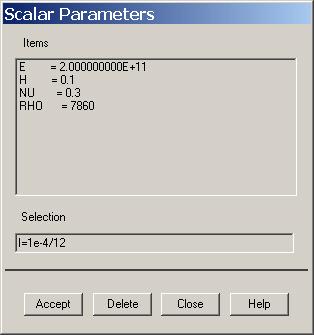
4 Example - Parameters Example0410 4

5 Example - Keypoints Preprocessor > Modeling > Create > Keypoints > In Active CS /PREP7 K,,,, General format: K,,,3, K,#,X,Y,Z K,,2,3, Note: An empty # result in automatic numbering. # Keypoint number X Keypoint x-coordinate Y Keypoint y-coordinate Z Keypoint z-coordinate Enter 0,0,0 and Press Apply Enter 0,3,0 and Press Apply Enter 2,3,0 and Press Apply Note: An empty box result in a zero. It is allowed to enter 0.0 in each box. Example0410 5


6 Example - Numbering Utility Menu > PlotCtrls > Numbering Switch on Keypoint numbers Press OK Example0410 6
7 Example - Lines Preprocessor > Modeling > Create > Lines > Lines > Straight Line Create a line between KP1 and KP2 and KP2 and KP3. L,1,2 L,2,3 HINT: By clicking with the righthand mouse button you shift between the Pick/Unpick function. This is indicated by the direction of the cursor arrow: Pick: upward arrow Unpick: downward arrow Press OK or Cancel to finish selection Example0410 7

8 Example - Plot - Nodes Plot Keypoints and Lines Example0410 8

9 Example Element Type Preprocessor > Element Type > Add/Edit/Delete Press Add Example0410 9

10 Example - Element Type Preprocessor > Element Type > Add/Edit/Delete Press Options Press Help to learn more about the element. Example

11 Example Real Constants Preprocessor > Real Constants > Add Place the cursor on the relevant element and press OK Example


12 Example - Real Constants Preprocessor > Real Constants > Add Enter cross sectional data Press OK Press Close to finish Example

13 Example - Material Properties Preprocessor > Material Props > Material Models Double Click to step in the material tree Example

14 Example - Material Properties Preprocessor > Material Props > Material Models Enter E Modulus of elasticity Enter nu Poisson s ratio Click here to Close Press OK Example

15 Example - Density Enter 7830 Press OK Example
16 Example - Meshing Preprocessor > Meshing > Size Cntrls > ManualSize > Lines > Picked Lines Select/Pick L1 Press OK when finish with selection Enter 30 Example

17 Example - Meshing Preprocessor > Meshing > Size Cntrls > ManualSize > Lines > Picked Lines Select/Pick L2 Press OK when finish with selection Enter 20 Example
18 Example - Meshing Preprocessor > Meshing > Mesh > Lines Select individual lines to be meshed by Picking NB: It is often necessary to Clear the model for example if Element Type is to be changed Select all lines defined to be meshed Example

19 Example Analysis Type File > Write DB log file Enter example0410.lgw Solution > Analysis Type > New Analysis Press OK Example

20 Example MA Analysis Options Select Block Lanczos Enter 10 Enter 10 Switch to Yes Press OK Example

21 Example MA Analysis Options Press OK Example
22 Example Define Loads Solution > Define Loads > Apply > Structural > Displacement > On Keypoints Select keypoint 1 Select UX and UY equal zero Press OK Example

23 Example Define Loads Solution > Define Loads > Apply > Structural > Displacement > On Keypoints Select keypoint 2 Select UY equal zero Press OK Example
24 Example - Damping Press OK Enter 0.02 for Constant damping ratio Example
25 Solution > Solve > Current LS Example - Solve Press OK Example
26 Example - Solve Press Close Press here to Close Example
27 Example - PostProcessing General Postproc > Plot Results > Deformed Shape Select Def+undeformed and Press OK Example

28 Example Results Summary Example

29 Example Read Results General Postproc > Plot Results > Deformed Shape Select Def+undeformed and Press OK Read first set Example

30 Example Mode 1 Example


31 Example Result viewer Select mode shape, the last mode read is displayed Press OK Example


32 Example Result viewer Select DOF solution and Def+undeformed Press OK and animation is controlled by the following dialog Example

33 Example Read Results Press OK Enter 3 and compare with Cook Example


34 Example - List Press OK Select Example
35 Example - List Compare result with Cook Example
36 Example Analysis Type File > Write DB log file Enter example0410.lgw Solution > Analysis Type > New Analysis Press OK Example


37 Example HRA Analysis Options Select Full Select Amplitud+ phase Press OK Example


38 Example Define Loads Solution > Define Loads > Apply > Structural > Force/Moment > On Keypoints Select keypoint 3 Change to FX Press OK to finish Enter 3000 Example


39 Example - Freq and Substps Enter 50 Enter 160 Enter 110 Select Stepped Example


40 Example - Damping Press OK Enter 0.02 for Constant damping ratio Example


41 Solution > Solve > Current LS Example - Solve Press OK Example
42 Example - Solve Press Close Example


43 Example TimeHistory Postpro Close this dialog box Example

44 Example Define Variables Press Add Example

45 Example Add Time-History Var. Select Nodal DOF result Press OK Enter 17 Press OK Press OK Select DOF solution and Translation UX Example


46 Example Graph Variables Enter 2 to plot UX for node 17 Press OK Example
47 Example Graph Variables Example
Course in ANSYS. Example0152. ANSYS Computational Mechanics, AAU, Esbjerg
 Course in Example0152 Example Truss 2D E = 210e09N/m 2 n = 0.3 L1 = L2 = L3 = 3.6m H = 3.118m a = b = 0.050mm F1 = 280kN F2 = 210kN F3 = 280kN F4 = 360kN Example0152 2 Example Truss 2D Objective: Compute
Course in ANSYS. Example Truss 2D. Example0150
 Course in ANSYS Example0150 Example Truss 2D Objective: Compute the maximum deflection Tasks: Display the deflection figure? Topics: Topics: Start of analysis, Element type, Real constants, Material, modeling,
Course in ANSYS. Example0154. ANSYS Computational Mechanics, AAU, Esbjerg
 Course in Example0154 Example Frame 2D E = 210000N/mm 2 n = 0.3 L= 1000mm H = 1000mm a = 20mm b = 50mm c = 400mm F = 10000N I = 208333N/mm 4 Example0154 2 Example Frame 2D Objective: Compute the maximum
Course in ANSYS. Example0504. ANSYS Computational Mechanics, AAU, Esbjerg
 Course in Example0504 Example Cantilever beam Objective: Compute the buckling load Tasks: Display the deflection figure? Topics: Topics: Start of analysis, Element type, Real constants, Material, modeling,
Course in ANSYS. Example0601. ANSYS Computational Mechanics, AAU, Esbjerg
 Course in Example0601 Example Turbine Blade Example0601 2 Example Turbine Blade Objective: Solve for the temperature distribution within the 6mm thick turbine blade, with 2mm x 6mm rectangular cooling
Example Cantilever beam
 Course in ANSYS Example0300 Example Cantilever beam Objective: Compute the maximum deflection and locate point of maximum deflection Tasks: How should this be modelled? Compare results with results obtained
Course in ANSYS. Example0505. ANSYS Computational Mechanics, AAU, Esbjerg
 Course in Example0505 Example Plate Objective: Compute the buckling load Tasks: How should this be modelled? Compare results with results obtained from norm calculations? Topics: Element type, Real constants,
Course in ANSYS. Example0500. ANSYS Computational Mechanics, AAU, Esbjerg
 Course in Example0500 Example Column beam Objective: Compute the critical buckling load and display the mode shape Tasks: Create a table and compare results with results obtained from buckling theory?
Course in ANSYS. Example0153. ANSYS Computational Mechanics, AAU, Esbjerg
 Course in Example0153 Example Offshore structure F Objective: Display the deflection figure and von Mises stress distribution Tasks: Import geometry from IGES. Display the deflection figure? Display the
Example Plate with a hole
 Course in ANSYS Example Plate with a hole A Objective: Determine the maximum stress in the x-direction for point A and display the deformation figure Tasks: Create a submodel to increase the accuracy of
Course in ANSYS. Example0303. ANSYS Computational Mechanics, AAU, Esbjerg
 Course in Example0303 Example Gear axle 3D Objective: Compute the maximum stress von Mise Tasks: How should this be modeled? Topics: Element type, Real constants, modeling, Plot results, output graphics,
Structural static analysis - Analyzing 2D frame
 Structural static analysis - Analyzing 2D frame In this tutorial we will analyze 2D frame (see Fig.1) consisting of 2D beams with respect to resistance to two different kinds of loads: (a) the downward
Structural static analysis - Analyzing 2D frame
 Structural static analysis - Analyzing 2D frame In this tutorial we will analyze 2D frame (see Fig.1) consisting of 2D beams with respect to resistance to two different kinds of loads: (a) the downward
Two Dimensional Truss
 Two Dimensional Truss Introduction This tutorial was created using ANSYS 7.0 to solve a simple 2D Truss problem. This is the first of four introductory ANSYS tutorials. Problem Description Determine the
Structural modal analysis - 2D frame
 Structural modal analysis - 2D frame Determine the first six vibration characteristics, namely natural frequencies and mode shapes, of a structure depicted in Fig. 1, when Young s modulus= 27e9Pa, Poisson
Institute of Mechatronics and Information Systems
 EXERCISE 2 Free vibrations of a beam arget Getting familiar with the fundamental issues of free vibrations analysis of elastic medium, with the use of a finite element computation system ANSYS. Program
Statically Indeterminate Beam
 Problem: Using Castigliano's Theorem, determine the deflection at point A. Neglect the weight of the beam. W 1 N/m B 5 cm H 1 cm 1.35 m Overview Anticipated time to complete this tutorial: 45 minutes Tutorial
Exercise 1. 3-Point Bending Using the GUI and the Bottom-up-Method
 Exercise 1 3-Point Bending Using the GUI and the Bottom-up-Method Contents Learn how to... 1 Given... 2 Questions... 2 Taking advantage of symmetries... 2 A. Preprocessor (Setting up the Model)... 3 A.1
NonLinear Analysis of a Cantilever Beam
 NonLinear Analysis of a Cantilever Beam Introduction This tutorial was created using ANSYS 7.0 The purpose of this tutorial is to outline the steps required to do a simple nonlinear analysis of the beam
NonLinear Materials AH-ALBERTA Web:
 NonLinear Materials Introduction This tutorial was completed using ANSYS 7.0 The purpose of the tutorial is to describe how to include material nonlinearities in an ANSYS model. For instance, the case
Structural modal analysis - 2D frame
 Structural modal analysis - 2D frame Determine the first six vibration characteristics, namely natural frequencies and mode shapes, of a structure depicted in Fig. 1, when Young s modulus= 27e9Pa, Poisson
Latch Spring. Problem:
 Problem: Shown in the figure is a 12-gauge (0.1094 in) by 3/4 in latching spring which supports a load of F = 3 lb. The inside radius of the bend is 1/8 in. Estimate the stresses at the inner and outer
Coupled Structural/Thermal Analysis
 Coupled Structural/Thermal Analysis Introduction This tutorial was completed using ANSYS 7.0 The purpose of this tutorial is to outline a simple coupled thermal/structural analysis. A steel link, with
Lecture # 5 Modal or Dynamic Analysis of an Airplane Wing
 Lecture # 5 Modal or Dynamic Analysis of an Airplane Wing Problem Description This is a simple modal analysis of a wing of a model airplane. The wing is of uniform configuration along its length and its
Bell Crank. Problem: Joseph Shigley and Charles Mischke. Mechanical Engineering Design 5th ed (New York: McGraw Hill, May 2002) page 87.
 page 87.") Problem: A cast-iron bell-crank lever, depicted in the figure below is acted upon by forces F 1 of 250 lb and F 2 of 333 lb. The section A-A at the central pivot has a curved inner surface with a radius
Problem: A cast-iron bell-crank lever, depicted in the figure below is acted upon by forces F 1 of 250 lb and F 2 of 333 lb. The section A-A at the central pivot has a curved inner surface with a radius
Ansys Lab Frame Analysis
 Ansys Lab Frame Analysis Analyze the highway overpass frame shown in Figure. The main horizontal beam is W24x162 (area = 47.7 in 2, moment of inertia = 5170 in 4, height = 25 in). The inclined members
Transient Thermal Conduction Example
 Transient Thermal Conduction Example Introduction This tutorial was created using ANSYS 7.0 to solve a simple transient conduction problem. Special thanks to Jesse Arnold for the analytical solution shown
Module 3: Buckling of 1D Simply Supported Beam
 Module : Buckling of 1D Simply Supported Beam Table of Contents Page Number Problem Description Theory Geometry 4 Preprocessor 7 Element Type 7 Real Constants and Material Properties 8 Meshing 9 Solution
6. Results Combination in Hexagonal Shell
 6. Results Combination in Hexagonal Shell Applicable CivilFEM Product: All CivilFEM Products Level of Difficulty: Moderate Interactive Time Required: 0 minutes Discipline: Load combinations results Analysis
Institute of Mechatronics and Information Systems
 EXERCISE 4 Free vibrations of an electrical machine model Target Getting familiar with the fundamental issues of free vibrations analysis of a simplified model of an electrical machine, with the use of
Chapter 2. Structural Tutorial
 Chapter 2. Structural Tutorial Tutorials> Chapter 2. Structural Tutorial Static Analysis of a Corner Bracket Problem Specification Problem Description Build Geometry Define Materials Generate Mesh Apply
ANSYS 5.6 Tutorials Lecture # 2 - Static Structural Analysis
 R50 ANSYS 5.6 Tutorials Lecture # 2 - Static Structural Analysis Example 1 Static Analysis of a Bracket 1. Problem Description: The objective of the problem is to demonstrate the basic ANSYS procedures
file://c:\documents and Settings\sala\Configuración local\temp\~hha54f.htm
 Página 1 de 26 Tutorials Chapter 2. Structural Tutorial 2.1. Static Analysis of a Corner Bracket 2.1.1. Problem Specification Applicable ANSYS Products: Level of Difficulty: Interactive Time Required:
ANSYS Tutorials. Table of Contents. Grady Lemoine
 ANSYS Tutorials Grady Lemoine Table of Contents Example 1: 2-D Static Stress Analysis in ANSYS...2 Example 2: 3-D Static Stress Analysis...5 Example 3: 2-D Frame With Multiple Materials and Element Types...10
Figure Random vibration analysis of a simply supported beam
 Example 6.5.8-1 [Spectrum Analysis] Determine the first two natural frequencies and the response of a damped two degree of freedom system subject to a random acceleration with a spectral density function
Buckling of Euler Column
 Problem: An Euler column with one end fixed and one end free is to be made of an aluminum alloy (E = 71 GPa). The cross sectional area of the column is 600 mm and the column is.5 m long. Determine the
Module 1.2: Moment of a 1D Cantilever Beam
 Module 1.: Moment of a 1D Cantilever Beam Table of Contents Page Number Problem Description Theory Geometry Preprocessor 6 Element Type 6 Real Constants and Material Properties 7 Meshing 9 Loads 10 Solution
Melting Using Element Death
 Melting Using Element Death Introduction This tutorial was completed using ANSYS 7.0 The purpose of the tutorial is to outline the steps required to use element death to model melting of a material. Element
Chapter 3. Thermal Tutorial
 Chapter 3. Thermal Tutorial Tutorials> Chapter 3. Thermal Tutorial Solidification of a Casting Problem Specification Problem Description Prepare for a Thermal Analysis Input Geometry Define Materials Generate
Module 1.5: Moment Loading of a 2D Cantilever Beam
 Module 1.5: Moment Loading of a D Cantilever Beam Table of Contents Page Number Problem Description Theory Geometry 4 Preprocessor 7 Element Type 7 Real Constants and Material Properties 8 Meshing 9 Loads
FINITE ELEMENT ANALYSIS LABORATORY MANUAL ANSYS. Course Instructor: Dr. R.Ganesan
 FINITE ELEMENT ANALYSIS MECH 460 LABORATORY MANUAL ANSYS Course Instructor: Dr. R.Ganesan Prepared by A. Zabihollah Approved by Dr. R. Ganesan Winter 2007 Table of Contents 1. INTRODUCTION.3 1.1 Starting
Module 1.7: Point Loading of a 3D Cantilever Beam
 Module 1.7: Point Loading of a D Cantilever Beam Table of Contents Page Number Problem Description Theory Geometry 4 Preprocessor 6 Element Type 6 Material Properties 7 Meshing 8 Loads 9 Solution 15 General
Instructions for Muffler Analysis
 Instructions for Muffler Analysis Part 1: Create the BEM mesh using ANSYS Specify Element Type Preprocessor > Element Type > Add/Edit/Delete Add Shell Elastic 4 Node 181 Close Specify Geometry Preprocessor
Coustyx Tutorial Indirect Model
 Coustyx Tutorial Indirect Model 1 Introduction This tutorial is created to outline the steps required to compute radiated noise from a gearbox housing using Coustyx software. Detailed steps are given on
ANSYS. Geometry. Material Properties. E=2.8E7 psi v=0.3. ansys.fem.ir Written By:Mehdi Heydarzadeh Page 1
 Attention: This tutorial is outdated, you will be redirected automatically to the new site. If you are not redirected, click this link to the confluence site. Problem Specification Geometry Material Properties
ECE421: Electronics for Instrumentation
 ECE421: Electronics for Instrumentation Lecture #8: Introduction to FEA & ANSYS Mostafa Soliman, Ph.D. March 23 rd 2015 Mostafa Soliman, Ph.D. 1 Outline Introduction to Finite Element Analysis Introduction
Release 10. Kent L. Lawrence. Mechanical and Aerospace Engineering University of Texas at Arlington SDC PUBLICATIONS
 ANSYS Release 10 Tutorial Kent L. Lawrence Mechanical and Aerospace Engineering University of Texas at Arlington SDC PUBLICATIONS Schroff Development Corporation www.schroff.com www.schroff-europe.com
ANSYS Tutorial Release 11.0
 ANSYS Tutorial Release 11.0 Structural & Thermal Analysis Using the ANSYS Release 11.0 Environment Kent L. Lawrence Mechanical and Aerospace Engineering University of Texas at Arlington SDC PUBLICATIONS
3. Check by Eurocode 3 a Steel Truss
 TF 3. Check by Eurocode 3 a Steel Truss Applicable CivilFEM Product: All CivilFEM Products Level of Difficulty: Moderate Interactive Time Required: 40 minutes Discipline: Structural Steel Analysis Type:
Structural static analysis dome
 Structural static analysis dome Calculate the maximum displacements of the dome depicted in Fig.1 and consisting of two types of beams with the crosssectional area: 0.08m*0.21m ( zig-zags ) and 0.07m*0.16m
Module 1.6: Distributed Loading of a 2D Cantilever Beam
 Module 1.6: Distributed Loading of a 2D Cantilever Beam Table of Contents Page Number Problem Description 2 Theory 2 Geometry 4 Preprocessor 7 Element Type 7 Real Constants and Material Properties 8 Meshing
Modelling and Analysis Lab (FEA)
") Channabasaveshwara Institute of Technology (Affiliated to VTU, Belagavi & Approved by AICTE, New Delhi) (NAAC Accredited & ISO 9001:2015 Certified Institution) NH 206 (B.H. Road), Gubbi, Tumakuru 572 216.
Channabasaveshwara Institute of Technology (Affiliated to VTU, Belagavi & Approved by AICTE, New Delhi) (NAAC Accredited & ISO 9001:2015 Certified Institution) NH 206 (B.H. Road), Gubbi, Tumakuru 572 216.
Dhanalakshmi College Of Engineering
 Dhanalakshmi College Of Engineering Manimangalam, Tambaram, Chennai 601 301 DEPARTMENT OF MECHANICAL ENGINEERING ME 6711 SIMULATION AND ANALYSIS LABORATORY VII SEMESTER - R 2013 LABORATORY MANUAL Name
University of Utah ME EN 6510/5510 Introduction to Finite Elements Fall 2005
 University of Utah ME EN 6510/5510 Introduction to Finite Elements Fall 2005 Running ANSYS on the CADE lab workstations CADE Lab Accounts You need to get account information in EMCB 224 from the operators
Analysis Steps 1. Start Abaqus and choose to create a new model database
 Source: Online tutorials for ABAQUS Problem Description The two dimensional bridge structure, which consists of steel T sections (b=0.25, h=0.25, I=0.125, t f =t w =0.05), is simply supported at its lower
FINITE ELEMENT ANALYSIS OF A PLANAR TRUSS
 Problem Description: FINITE ELEMENT ANALYSIS OF A PLANAR TRUSS Instructor: Professor James Sherwood Revised: Dimitri Soteropoulos Programs Utilized: Abaqus/CAE 6.11-2 This tutorial explains how to build
300 N All lengths in meters. Step load applied at time 0.0.
 Problem description In this problem, we subject the beam structure of problem 1 to an impact load as shown. 300 N 0.02 0.02 1 All lengths in meters. Step load applied at time 0.0. E = 2.07 10 11 N/m 2
Normal Modes - Rigid Element Analysis with RBE2 and CONM2
 LESSON 16 Normal Modes - Rigid Element Analysis with RBE2 and CONM2 Y Y Z Z X Objectives: Create a geometric representation of a tube. Use the geometry model to define an analysis model comprised of plate
Abaqus/CAE (ver. 6.10) Stringer Tutorial
 Stringer Tutorial") Abaqus/CAE (ver. 6.10) Stringer Tutorial Problem Description A table made of steel tubing with a solid steel top and shelf is loaded with an oblique impulse load. Determine the transient response of the
Abaqus/CAE (ver. 6.10) Stringer Tutorial Problem Description A table made of steel tubing with a solid steel top and shelf is loaded with an oblique impulse load. Determine the transient response of the
MECH 3130: Mechanics of Materials. Fall Laboratory Manual. Volume II
 MECH 3130: Mechanics of Materials Fall 2015 Laboratory Manual Volume II Instructor Dr. Peter Schwartz Dr. Nels Madsen Lab Teaching Assistants Quang Nguyen: qzn0003@auburn.edu Abhiram Pasumarthy rzp0025@auburn.edu
Linear Static Analysis for a 3-D Slideline Contact
 WORKSHOP PROBLEM 10a Linear Static Analysis for a 3-D Slideline Contact Objectives: Demonstrate the use of slideline contact. Run an MSC/NASTRAN linear static analysis. Create an accurate deformation plot
Normal Modes - Rigid Element Analysis with RBE2 and CONM2
 APPENDIX A Normal Modes - Rigid Element Analysis with RBE2 and CONM2 T 1 Z R Y Z X Objectives: Create a geometric representation of a tube. Use the geometry model to define an analysis model comprised
Command. Command BOUNDARY CONDITIONS. 4.4 Mode analysis of a one-axis precision moving table using elastic hinges 201
 4.4 Mode analysis of a one-axis precision moving table using elastic hinges 201 C D Figure 4.96 Window of Element Sizes on Picked Lines. (5) Pick the area of the table on NSYS Graphics window and click
Stresses in an Elliptical Beam
 Problem: An offset tensile link is shaped to clear an obstruction with a geometry as shown in the figure. The cross section at the critical location is elliptical, with a major axis of 4 in and a minor
Interface with FE programs
 Page 1 of 47 Interdisciplinary > RFlex > Flexible body Interface Interface with FE programs RecurDyn/RFlex can import FE model from ANSYS, NX/NASTRAN, MSC/NASTRAN and I-DEAS. Figure 1 RecurDyn/RFlex Interface
Normal Modes - Rigid Element Analysis with RBE2 and CONM2
 APPENDIX A Normal Modes - Rigid Element Analysis with RBE2 and CONM2 T 1 Z R Y Z X Objectives: Create a geometric representation of a tube. Use the geometry model to define an analysis model comprised
5. Shell Reinforcement According To Eurocode 2
 5. Shell Reinforcement According To Eurocode Applicable CivilFEM Product: All CivilFEM Products Level of Difficulty: Moderate Interactive Time Required: 5 minutes Discipline: Concrete Shell Reinforcement
Dynamics and Vibration. Tutorial
 Dynamics and Vibration Tutorial Startup To use Dynamics and Vibration Analysis (DVA), you must first start TK Solver. Once in TK, select Dynamics & Vibration from the Applications Menu. The DVA Menu will
Course in. FEM ANSYS Classic
 Course in Geometric modeling Modeling Programme for Lesson: Modeling considerations Element Type Real Constants Material Properties Sections Geometry/Modeling WorkPlane & Coordinate systems Keypoints Lines
ANSYS EXERCISE ANSYS 5.6 Temperature Distribution in a Turbine Blade with Cooling Channels
 I. ANSYS EXERCISE ANSYS 5.6 Temperature Distribution in a Turbine Blade with Cooling Channels Copyright 2001-2005, John R. Baker John R. Baker; phone: 270-534-3114; email: jbaker@engr.uky.edu This exercise
Introduction To Finite Element Analysis
 Creating a Part In this part of the tutorial we will introduce you to some basic modelling concepts. If you are already familiar with modelling in Pro Engineer you will find this section very easy. Before
Prescribed Deformations
 u Prescribed Deformations Outline 1 Description 2 Finite Element Model 2.1 Geometry Definition 2.2 Properties 2.3 Boundary Conditions 2.3.1 Constraints 2.3.2 Prescribed Deformation 2.4 Loads 2.4.1 Dead
COMPUTER AIDED ENGINEERING. Part-1
 COMPUTER AIDED ENGINEERING Course no. 7962 Finite Element Modelling and Simulation Finite Element Modelling and Simulation Part-1 Modeling & Simulation System A system exists and operates in time and space.
ANSYS Tutorial Version 6
 ANSYS Tutorial Version 6 Fracture Analysis Consultants, Inc www.fracanalysis.com Revised: November 2011 Table of Contents: 1.0 Introduction... 4 2.0 Tutorial 1: Crack Insertion and Growth in a Cube...
Appendix B: Creating and Analyzing a Simple Model in Abaqus/CAE
 Getting Started with Abaqus: Interactive Edition Appendix B: Creating and Analyzing a Simple Model in Abaqus/CAE The following section is a basic tutorial for the experienced Abaqus user. It leads you
Essay 5 Tutorial for a Three-Dimensional Heat Conduction Problem Using ANSYS
 Essay 5 Tutorial for a Three-Dimensional Heat Conduction Problem Using ANSYS 5.1 Introduction The problem selected to illustrate the use of ANSYS software for a three-dimensional steadystate heat conduction
300 N All lengths in meters. Step load applied at time 0.0. The beam is initially undeformed and at rest.
 Problem description In this problem, we subject the beam structure of problem 1 to an impact load as shown. 300 N 0.02 0.02 1 All lengths in meters. Step load applied at time 0.0. E = 2.07 10 11 N/m 2
LAB MANUAL. Dharmapuri ME6711-SIMULATION AND ANALYSIS. Regulation : Branch : B.E. Mechanical Engineering
 Dharmapuri 636 703 LAB MANUAL Regulation : Branch : 2013 B.E. Mechanical Engineering Year & Semester : IV Year / VII Semester ME6711-SIMULATION AND ANALYSIS Varuvan Vadivelan Institute of Technology, Dharmapuri
Defining shell thicknesses Plotting 5 and 6 DOF nodes Plotting shell thicknesses Plotting results on the top, midsurface and bottom of the shell
 Problem description A shell corner is analyzed first for its static response due to a concentrated load, then for its natural frequencies and mode shapes. In the static analysis, we will demonstrate the
1.992, 2.993, 3.04, 10.94, , Introduction to Modeling and Simulation Prof. F.-J. Ulm Spring FE Modeling Example Using ADINA
 1.992, 2.993, 3.04, 10.94, 18.996, 22.091 Introduction to Modeling and Simulation Prof. F.-J. Ulm Spring 2002 FE Modeling Example Using ADINA H Hgρ w ργ H = B = 10 m g = 9.81 m/s 2 ρ = 2400 kg/m 3 ρ w
11. Push-over analysis
 . Push-over analysis Applicable CivilFEM Product: All CivilFEM Products Level of Difficulty: Moderate Interactive Time Required: 90 minutes Discipline: Structural Steel Analysis Type: Push Over Element
Statically Indeterminate Beam
 Problem: A rectangular aluminum bar.5 inches thick and 2 inches wide is welded to fixed supports at the ends, and the bar supports a load W=800 lb, acting through the pin as shown. Find the reactions at
Exercise 2: Bike Frame Analysis
 Exercise 2: Bike Frame Analysis This exercise will analyze a new, innovative mountain bike frame design under structural loads. The objective is to determine the maximum stresses in the frame due to the
Geometric Linear Analysis of a Cantilever Beam
 WORKSHOP PROBLEM 2a Geometric Linear Analysis of a Cantilever Beam Objectives: Demonstrate the use of geometric linear analysis. Observe the behavior of the cantilever beam under four increasing load magnitudes.
FINITE ELEMENT ANALYSIS OF A PROPPED CANTILEVER BEAM
 FINITE ELEMENT ANALYSIS OF A PROPPED CANTILEVER BEAM Problem Description: Instructor: Professor James Sherwood Revised: Venkat Putcha, Dimitri Soteropoulos Programs Utilized: HyperMesh Desktop 12.0, OptiStruct,
Linear Static Analysis of a Plate with Hole
 Fergyanto E. Gunawan (f.e.gunawan@gmail.com) Department of Mechanical Engineering Toyohashi University of Technology Objectives: Modeling a symmetric structure Bottom-up and top-down approaches in modeling
Abaqus/CAE (ver. 6.9) Vibrations Tutorial
 Vibrations Tutorial") Abaqus/CAE (ver. 6.9) Vibrations Tutorial Problem Description The two dimensional bridge structure, which consists of steel T sections, is simply supported at its lower corners. Determine the first 10
Abaqus/CAE (ver. 6.9) Vibrations Tutorial Problem Description The two dimensional bridge structure, which consists of steel T sections, is simply supported at its lower corners. Determine the first 10
Problem O. Isolated Building - Nonlinear Time History Analysis. Steel E =29000 ksi, Poissons Ratio = 0.3 Beams: W24X55; Columns: W14X90
 Problem O Isolated Building - Nonlinear Time History Analysis Steel E =29000 ksi, Poissons Ratio = 0.3 Beams: W24X55; Columns: W14X90 Rubber Isolator Properties Vertical (axial) stiffness = 10,000 k/in
Exercise 2: Bike Frame Analysis
 Exercise 2: Bike Frame Analysis This exercise will analyze a new, innovative mountain bike frame design under structural loads. The objective is to determine the maximum stresses in the frame due to the
Creating and Analyzing a Simple Model in Abaqus/CAE
 Appendix B: Creating and Analyzing a Simple Model in Abaqus/CAE The following section is a basic tutorial for the experienced Abaqus user. It leads you through the Abaqus/CAE modeling process by visiting
Figure E3-1 A plane struss structure under applied loading. Start MARC Designer. From the main menu, select STATIC STRESS ANALYSIS.
 Example 3 Static Stress Analysis on a Plane Truss Structure Problem Statement: In this exercise, you will use MARC Designer software to carry out a static stress analysis on a simple plane truss structure,
CE366/ME380 Finite Elements in Applied Mechanics I Fall 2007
 CE366/ME380 Finite Elements in Applied Mechanics I Fall 2007 FE Project 1: 2D Plane Stress Analysis of acantilever Beam (Due date =TBD) Figure 1 shows a cantilever beam that is subjected to a concentrated
Random Vibration Analysis of a Circuit Board. Sean Harvey August 2000 CSI Tip of the Week
 Random Vibration Analysis of a Circuit Board Sean Harvey August 2000 CSI Tip of the Week Random Vibrations Outline Introduction Sample Problem Description Pre Processing Steps Omitted Interactive steps
Transient Response of a Rocket
 Transient Response of a Rocket 100 Force 0 1.0 1.001 3.0 Time Objectives: Develope a finite element model that represents an axial force (thrust) applied to a rocket over time. Perform a linear transient
Abaqus/CAE (ver. 6.12) Vibrations Tutorial
 Vibrations Tutorial") Abaqus/CAE (ver. 6.12) Vibrations Tutorial Problem Description The two dimensional bridge structure, which consists of steel T sections, is simply supported at its lower corners. Determine the first 10
Abaqus/CAE (ver. 6.12) Vibrations Tutorial Problem Description The two dimensional bridge structure, which consists of steel T sections, is simply supported at its lower corners. Determine the first 10
Abaqus CAE Tutorial 1: 2D Plane Truss
 ENGI 7706/7934: Finite Element Analysis Abaqus CAE Tutorial 1: 2D Plane Truss Lab TA: Xiaotong Huo EN 3029B xh0381@mun.ca Download link for Abaqus student edition: http://academy.3ds.com/software/simulia/abaqus-student-edition/
A rubber O-ring is pressed between two frictionless plates as shown: 12 mm mm
 Problem description A rubber O-ring is pressed between two frictionless plates as shown: Prescribed displacement C L 12 mm 48.65 mm A two-dimensional axisymmetric analysis is appropriate here. Data points
Getting Started. These tasks should take about 20 minutes to complete. Getting Started
 Getting Started Getting Started This tutorial will guide you step-by-step through your first ELFINI and Generative Part Structural Analysis session, allowing you to get acquainted with the product. You
Problem description C L. Tank walls. Water in tank
 Problem description A cylindrical water tank is subjected to gravity loading and ground accelerations, as shown in the figures below: Tank walls Water in tank Wall thickness 0.05 C L 5 g=9.81 m/s 2 Water:
Abaqus/CAE (ver. 6.11) Nonlinear Buckling Tutorial
 Nonlinear Buckling Tutorial") Abaqus/CAE (ver. 6.11) Nonlinear Buckling Tutorial Problem Description This is the NAFEMS 1 proposed benchmark (Lee s frame buckling) problem. The applied load is based on the normalized (EI/L 2 ) value
Abaqus/CAE (ver. 6.11) Nonlinear Buckling Tutorial Problem Description This is the NAFEMS 1 proposed benchmark (Lee s frame buckling) problem. The applied load is based on the normalized (EI/L 2 ) value