Frontier FiOS Gateway USER GUIDE. Model: FiOS-G1100. Copyright 2016 Frontier Communications. All Rights Reserved.
|
|
|
- Ashlee Terry
- 6 years ago
- Views:
Transcription

1 Frontier FiOS Gateway USER GUIDE Model: FiOS-G1100
2 CONTENTS 01/ INTRODUCTION. 1.0 Package Contents. 1.1 System Requirements. 1.2 Features. 1.3 Getting to Know Your Gateway 02/ CONNECTING YOUR GATEWAY 2.0 Setting Up Your Gateway 03/ WIRELESS SETTINGS 3.0 Overview 3.1 Wireless Status 3.2 Basic Security Settings 3.3 Advanced Security Settings 3.4 Wireless MAC Authentication Mode
3 3.6 Other Advanced Wireless Options 3.7 Guest Wi-Fi Settings 04/ CONFIGURING MY NETWORK SETTINGS. 4.0 Accessing My Network Settings. 4.1 Using My Network Settings. 4.2 Computer Network Configuration. 4.3 Main Screen 05/ CONFIGURING MY NETWORK SETTINGS. 5.1 Network (Home/Office) Connection. 5.2 Broadband Connection. 5.3 Wireless Access Point Connection. 5.4 Broadband Ethernet/Coax
4 06/ ADVANCED NETWORK SETTINGS 6.1 Port Forwarding 6.2 Port Triggering 6.3 DMZ Host 07/ SETTING PARENTAL CONTROLS 7.0 Activating Parental Controls 7.1 Rule Summary 08/ CONFIGURING ADVANCED SETTINGS MONITORING YOUR GATEWAY. 8.0 Using Advanced Settings. 8.1 Utilities. 8.2 DNS Settings. 8.3 Network Settings. 8.4 Routing. 8.5 Date and Time 167
5 . 8.6 Configuration Settings 09/ Monitoring 9.1 System Logging 9.2 Full Status/System wide Monitoring 9.3 Bandwidth Monitoring 10/ TROUBLESHOOTING 10.0 Troubleshooting 189 Tips 10.1 Frequently 195 Asked Questions of Connections 9.4 Traffic / SPECIFICATIONS General Specifications LED Indicators Environmental Parameters
6 12/ NOTICES 12.0 Regulatory 207 Compliance Notices
7 01/ INTRODUCTION. 1.0 Package Contents. 1.1 System Requirements. 1.2 Features. 1.3 Getting to Know Your Gateway The FiOS Gateway lets you transmit and distribute digital entertainment and information to multiple devices in your home/office. Your Gateway supports networking using coaxial cables, Ethernet, or Wi-Fi, making it one of the most versatile and powerful gateways available.
8 PACKAGE CONTENTS, SYSTEM REQUIREMENTS AND FEATURES 1.0/ PACKAGE CONTENT Your package contains: The Frontier FiOS Gateway Power adapter LAN Ethernet cable (yellow) WAN Ethernet cable (white) Quick Start Guide 1.1/ SYSTEM REQUIREMENTS System and software requirements are: A computer or other network device supporting Wi-Fi or wired Ethernet A web browser, such as ChromeTM, Firefox, Internet Explorer 8 or higher, or Safari 5.1 or higher 1.2/ FEATURES Your Gateway features include: Support for multiple networking standards, including WAN Gigabit Ethernet and MoCA 2.0 interfaces LAN b/g/n/ac, Gigabit Ethernet and MoCA 2.0 interfaces Integrated wired networking with 4-port Ethernet switch
9 and Coax (MoCA) Ethernet supports speeds up to 1000 Mbps MoCA 2.0 and 1.1 enabled to support speeds up to 700 Mbps over coaxial cable Integrated wireless networking with b/g/n/ac access point featuring: Enabled b capable speeds (based on device) Enabled g capable speeds (based on device) Enabled n capable speeds (based on device) Enabled ac capable speeds (based on device) Enterprise-level security, including: Fully customizable firewall with Stateful Packet Inspection (SPI) Content filtering with URL-keyword based filtering, parental controls, and customizable filtering policies per computer Intrusion detection with Denial of Service protection against IP spoofing attacks, scanning attacks, IP fragment overlap exploit, ping of death, and fragmentation attacks Event logging
10 01/ INTRODUCTION 8 MAC address filtering Static NAT FEATURES AND GETTING TO KNOW YOUR GATEWAY Port forwarding Port triggering Access control Advanced wireless protection featuring WPA2/WPA Mixed Mode, WEP 64/128 bit encryption, and MAC address filtering Options, including: DHCP server WAN interface auto-detection Dynamic DNS DNS server LAN IP and WAN IP address selection MAC address cloning IPv6 support QoS support (end to end layer 2/3) featuring:
, and queuing to LAN-side devices Remote management and secured remote management using HTTPS Static routing VPN (VPN")
11 Differentiated Services (Diffserv), 802.1p/q prioritization, and pass- through of WAN-side DSCPs, Per Hop Behaviors (PHBs), and queuing to LAN-side devices Remote management and secured remote management using HTTPS Static routing VPN (VPN pass through only) 01/ INTRODUCTION 10 IGMP Daylight savings time support 1.3/ GETTING TO KNOW YOUR GATEWAY 1.3a/ FRONT PANEL The front panel has two lighted indicators and a WPS (Wi-Fi Protected Setup) button. The Power/Internet light will be on and solid when your Gateway is turned on, connected to the Internet, and functioning normally. The Wireless light will be on when your Gateway Wi-Fi is turned on. For additional information on the front lights and error indications, refer the Troubleshooting section in this Guide. The WPS button is used to initiate Wi-Fi Protected Setup. This is an easy way to add WPS capable devices to your wireless network.
12 When WPS is initiated from your Gateway, the wireless light slowly flashes white for up to two minutes, allowing time to complete the WPS pairing process on your wireless device (also known as a wireless client). When a device begins connecting to your Gateway using WPS, the wireless light rapidly flashes white for a few seconds, then turns solid white as the connection completes. GETTING TO KNOW YOUR GATEWAY If there is an error during the WPS pairing process, the wireless light flashes red rapidly for two minutes after the error occurs. The WPS button can also be used to reboot the router. To perform a soft reboot, press and hold the WPS button for at least 10 seconds. 1.3b/ SIDE PANEL The side panel of your Gateway has a label that contains important information about your device, including the default settings for the Gateway s wireless network name (ESSID), wireless password (WPA2 key), local URL for accessing the Gateway s administrative pages, and Gateway administrator password. The label also contains a QR code that you can scan with your smartphone, tablet, or other cameraequipped Wi-Fi device to allow you to automatically connect your device to your Wi-Fi network without typing in a password (requires a QR code reading app with support for Wi-Fi QR codes).
![1.3c/ REAR PANEL The rear panel of your Gateway has 8 ports; COAX, Ethernet LAN [4],](/docs-images/72/67972836/images/13-0.jpg "Ethernet WAN, and USB [2].")
13 1.3c/ REAR PANEL The rear panel of your Gateway has 8 ports; COAX, Ethernet LAN [4], Ethernet WAN, and USB [2]. The rear panel also includes a DC power jack and a reset button.

14 GETTING TO KNOW YOUR GATEWAY USB - provides up to 500 ma at 5 VDC for attached devices. For example, you could charge a cell phone. In the future, with a firmware upgrade, the USB host functionality may be available for other devices, such as external storage and cameras. Firmware updates are performed automatically by Frontier.
15 Reset Button - allows you to reset your Gateway to the factory default settings. To reset the Gateway, press and hold the Reset button for at least three seconds. Ethernet LAN - connects devices to your Gateway using Ethernet cables to join the local area network (LAN). The four Ethernet LAN ports are 10/100/1000 Mbps auto-sensing and can be used with either straight-through or crossover Ethernet cables. HAN Expansion Port - provides for future hardware upgrades to add support for Home Area Networking capabilities. Ethernet WAN - connects your Gateway to the Internet using an Ethernet cable. Coax WAN and LAN - connects your Gateway to the Internet and/or to other MoCA devices using a coaxial cable. Warning: The WAN Coax Port is intended for connection to FiOS only. It must not be connected to any exterior or interior coaxial wires not designated for FiOS. Power - connects your Gateway to an electrical wall outlet using the supplied power adapter. Warning: The included power adapter is for home use only, supporting voltages from Vac. Do not use in environments with greater than 240Vac. If you are replacing an existing wall mounted router, you do not need to remove the mounting screws from the wall. The existing mounting screws will fit the new bracket. To mount your Gateway to a wall: 1. Remove the foot by turning the Gateway upside down and removing the single screw that holds the foot to the Gateway.

16 2. Slide the foot toward the front of the Gateway and pull the foot from the holes. You may need to wiggle the foot slightly. 3. You may use the wall mount bracket as a template for positioning the Gateway. 1.3d/ MOUNTING THE GATEWAY TO A WALL GETTING TO KNOW YOUR GATEWAY 4. Mark the mounting holes, then remove the wall mount bracket from the wall. 5. Drill holes for the screw anchors. 6. Insert the screw anchors in the holes in the wall, then insert the screws into the screw anchors and tighten the screws. Leave screws extended about 0.2 inches from the wall. 7. Verify the screws are positioned correctly by placing the wall bracket on the screws. Remove the wall bracket from the wall. 8. Place the Gateway on the wall bracket and slide the Gateway forward until it locks in place.

17 9. To secure the Gateway, attach the bracket to the Gateway using the single screw you removed from the foot. 10. Slide the wallmount bracket with the attached Gateway on the screws, then slide the bracket down until it locks in place.
18 02/ CONNECTING YOUR GATEWAY. 2.0 Setting Up Your Gateway. 2.1 Computer Network Configuration. 2.2 Main Screen SETTING UP YOUR GATEWAY Connecting your Gateway and accessing its web-based Graphical User Interface (GUI) are both simple procedures. Accessing the GUI may vary slightly, depending on your device s operating system and web browser.
19 2.0/ SETTING UP YOUR GATEWAY There are three basic steps to setting up your Gateway: Step1: Connect your Gateway to the Internet Step 2: Connect your network device to your Gateway Step 3: Configure your Gateway Before you begin, if you are replacing an existing Gateway, disconnect it. Remove all old Gateway components, including the power supply. They will not work with your new Gateway. 2.0a/ STEP 1 - CONNECT YOUR GATEWAY 1. Remove your Gateway, Ethernet cables, and power adapter from the box. 2. Locate your high-speed Internet (WAN) outlet. This would be the wall jack installed previously by Frontier. Note the type of jack may be either Ethernet or coaxial. 3. Connect your Gateway to the Internet (WAN). If connecting the WAN using Ethernet, use the supplied white Ethernet cable and plug one end into the white Ethernet WAN port on the back of your Gateway. Plug the other end of the cable into the high-speed Ethernet wall jack. If connecting the WAN using coaxial cable, locate a coaxial cable and connect one end to the coax port on the back of your Gateway. Connect the other end of the coaxial cable to a coax wall jack. Tighten the coaxial cables by hand until snug. The cables should
20 not require a wrench. 4. Plug the power cord into the power port on the back of your Gateway and then into a power outlet. The Gateway automatically turns on as soon as power is plugged in. Important: Wait until the Power/Internet light on the front of the Gateway stops flashing and is solid white. If the light turns red, check the troubleshooting steps in the Troubleshooting section of the user guide. 2.0b/ STEP 2 - CONNECT YOUR DEVICE TO YOUR GATEWAY If connecting a device using wired Ethernet (preferred for initial setup): Plug one end of the supplied yellow Ethernet cable into one of the four yellow Ethernet ports in the back of your Gateway. Alternatively, you can use your own Ethernet cable of any color to connect from the yellow Ethernet ports on the back of your Gateway to your device with an Ethernet connector. Plug the other end of the yellow Ethernet cable into the Ethernet port of your network device. If connecting a wireless device: Access the Wi-Fi setting on your wireless device, then select your new Gateway using the wireless network name (ESSID) shown on the sticker located on the side of your Gateway. Enter the wireless password (WPA2 key) also shown on the sticker. 2.0c/ STEP 3 - CONFIGURE YOUR GATEWAY:

21 1. Open a web browser on the device connected to your Gateway network. 2. In the browser address field (URL), enter: myfiosgateway.com, then press the Enter key on your keyboard. Alternately, you can enter: SETTING UP YOUR GATEWAY The first time you access your Gateway, an Easy Setup Wizard displays to help step you through the setup process.
 to personalize your Guest Wi-Fi Name and Password.")
22 3. In the Admin Password field, enter the password that is printed next to the Administrator Password on the label on the side of your Gateway. 4. Click Next. The Personalize Your Wi-Fi Settings screen displays. Click on the check box next to Setup your Guest Wi-Fi (Optional) to personalize your Guest Wi-Fi Name and Password. For your protection, your Gateway is pre-set at the factory to use WPA2/WPA mixed mode (Wi-Fi Protected Access) encryption for your wireless network. This is the best setting for most users and provides maximum security.

23 SETTING UP YOUR GATEWAY AND COMPUTER NETWORK CONFIGURATION 5. Click Continue. The Apply to Save Your Wi-Fi Settings screen appears. You have an option of saving the Wi-Fi settings as an image on your device by clicking the Save as Picture button. After you click Save as Picture to save your Wi-Fi settings as an image, click Apply to save the Wi-Fi changes to your Gateway. Important: If you are on a Wi-Fi device when setting up your Gateway, you will be disconnected from the Wi-Fi network when you change the Wi-Fi name or Wi-Fi password. When this occurs, your Gateway will detect this situation and prompt you to reconnect using the new settings.

24 Congratulations! You re All Set Up screen displays once your Gateway verifies the final settings and has successfully connected to the Internet and is ready for use. You can click on Main Router Settings to access the Main screen of the Gateway or click on Start Browsing and you will be directed to the V website. If your Gateway is subsequently reset to the factory default settings, the settings printed on the label will again be in effect. If your Gateway fails to connect, follow the troubleshooting steps in the Troubleshooting section of this guide. 2.1/ COMPUTER NETWORK CONFIGURATION Each network interface on your computer should either automatically obtain an IP address from the upstream Network DHCP server (default configuration) or be manually configured with a statically defined IP address and DNS address. We recommend leaving this setting as is. COMPUTER NETWORK CONFIGURATION 2.1a/ CONFIGURING DYNAMIC IP ADDRESSING To configure a
25 computer to use dynamic IP addressing: 1. In the Control Panel, locate Network and Internet, then select View Network Status and Tasks. 2. In the View your active networks Connect or disconnect section, click Local Area Connection in the Connections field. The Local Area Connection Status window displays. 3. Click Properties. The Local Area Connection Properties window displays. 4. Select Internet Protocol Version 4 (TCP/IPv4), then click Properties. The Internet Protocol Version 4 (TCP/IPv4) Properties window displays. 5. Click the Obtain an IP address automatically radio button. 6. Click the Obtain DNS server address automatically radio button, then click OK. 7. In the Local Area Connection Properties window, click OK to save the settings. 8. To configure Internet Protocol Version 6 (TCP/IPv6) to use dynamic IP addressing, repeat step 1 to 7. However for step 3, select Internet Protocol Version 6 (TCP/IPv6) in the Properties option (refer to IPv6 section for Gateway configuration). MACINTOSH OS X 1. Click the Apple icon in the top left corner of the desktop. A menu displays. 2. Select System Preferences. The System Preferences window displays.
26 3. Click Network. 4. Verify that Ethernet, located in the list on the left, is highlighted and displays Connected. 5. Click Assist Me. 6. Follow the instructions in the Network Diagnostics Assistant. 2.1b/ CONNECTING OTHER COMPUTERS & NETWORK DEVICES You can connect your Gateway to other computers or set top boxes using an Ethernet cable, wireless connection (Wi-Fi), or coaxial cable. ETHERNET 1. Plug one end of an Ethernet cable into one of the open yellow Ethernet ports on the back of your Gateway. 2. Plug the other end of the Ethernet cable into an Ethernet port on the computer. 3. Repeat these steps for each computer to be connected to your Gateway using Ethernet. You can connect up to four. COMPUTER NETWORK CONFIGURATION CONNECTING A WI-FI DEVICE USING WPS Wi-Fi Protected Setup (WPS) is an easier way for many devices to set up a secure wireless network connection. Instead of manually entering passwords or multiple keys on each wireless client, such as a laptop, printer, or external hard drive, your Gateway creates a secure wireless network.

27 In most cases, this only requires the pressing of two buttons one on your Gateway and one on the wireless client. This could be either a built-in button or one on a compatible wireless adapter/card, or a virtual button in software. Once completed, this allows wireless clients to join your wireless network. To initialize the WPS process, you can either press and release the WPS button located on the front of your Gateway or use the GUI and press the on-screen button. You can easily add wireless devices to your wireless network using the WPS option if your wireless device supports the WPS feature. To access WPS using the user interface: 1. From the Main menu, select Wireless Settings, then select Wi-Fi Protected Setup (WPS). 2. Enable the protected setup by moving the selector to On.
28 3. Use one of the following methods: If your wireless client device has a WPS button, press the WPS button on your Gateway, then click the WPS button on your wireless device (client) to start the WPS registration process. If your client device has a WPS PIN, locate the PIN printed on the client s label or in the client documentation. COMPUTER NETWORK CONFIGURATION AND MAIN SCREEN Enter the PIN number in the Client WPS PIN field. The Client WPS PIN field is located in the section B - PIN Enrollment on the user interface. Click Register. Alternatively, you can enter the Gateway s PIN shown on this screen into the WPS user interface of your device, if this PIN mode is supported by your wireless device. 4. After pressing the WPS button on your Gateway, you have two minutes to press the WPS button on the client device before the WPS session times out. When the WPS button on your Gateway is pressed, the Wireless light on the front of your Gateway begins flashing white. The flashing continues until WPS pairing to the client device completes successfully. At this time, the Wireless light turns solid white. If WPS fails to establish a connection to a wireless client device within two minutes, the Wireless light on your Gateway flashes red for two minutes to indicate the WPS pairing process was unsuccessful. After flashing red, the light returns to solid white to indicate that Wi-Fi is on.
29 CONNECTING A WI-FI DEVICE USING A PASSWORD 1. Verify each device that you are connecting wirelessly (using Wi-Fi) has a built-in wireless or external wireless adapter. 2. Open the device s wireless settings application. 3. Select your Gateway s wireless network name (SSID) from the device s list of discovered wireless networks. 4. When prompted, enter your Gateway s wireless password (WPA2 key) into the device s wireless settings. Your Gateway s default wireless network name and wireless password are located are on the sticker on the side of your Gateway. 5. Verify the changes were implemented by using the device s web browser to access a site on the Internet. 6. Repeat these steps for every device that you are wirelessly connecting to your Gateway. COAXIAL 1. Verify all coax devices are turned off. 2. Disconnect any adapter currently connected to the coaxial wall jack in the room where your Gateway is located. 3. Connect one end of the coaxial cable to the coaxial wall jack and the other end to the Coax port on your network device. 4. Power up the network device.
30 2.2/ MAIN SCREEN When you log into your Gateway, the page displays showing the Main navigation menu at the top of the page and your Gateway s Status, including Quick Links, My Network, and Additional Resources display in the body of the page.
31 2.2a/ MENU The Main menu links across the top of the page to the following configuration options and chapters: Wireless Settings - Chapter 3 My Network - Chapter 5 Firewall - Chapter 6 Parental Controls - Chapter 7 Advanced - Chapter 8 System Monitoring - Chapter 9 2.2b/ STATUS This section displays the status of your Gateway s local network (LAN) and Internet connection (WAN). BROADBAND CONNECTION Broadband Connection displays the state of the broadband connection: Broadband interface: Ethernet or Coax Connected status: Connected or No Connection Connection Type: DHCP or Static WAN IP address: Address of the broadband connection QUICK LINKS Quick Links contains frequently accessed documentation, such as User Guide and Help, and settings, such as Change Wireless
32 Settings, Change Admin Password, and Port Forwarding as well as Logout. MY NETWORK My Network displays the connection type, IP address, and status of all devices that have accessed or are currently connected to the network.
33 03/ WIRELESS SETTINGS. 3.0 Overview. 3.1 Wireless Status. 3.2 Basic Security Settings. 3.3 Advanced Security Settings. 3.4 Wireless MAC Authentication Mode. 3.6 Other Advanced Wireless Options. 3.7 Guest Wi-Fi Settings OVERVIEW Wireless networking enables you to free yourself from wires and plugs, making
34 your devices more accessible and easier to use. You can create a wireless network, including accessing and configuring wireless security options. 3.0/ OVERVIEW Your Gateway provides you with wireless connectivity using the b, g, n, or ac standards. These are the most common wireless standards b has a maximum data rate of 11 Mbps, g has a maximum data rate of 54 Mbps, n has a maximum data rate of 450 Mbps, and ac has a maximum data rate of 1300 Mbps b and g standards operate in the 2.4 GHz range n operates in both the 2.4 GHz and 5 GHz ranges ac operates in the 5 GHz range. Note: b is a legacy mode and is not recommended. Even one b device connected to the network will slow your entire wireless network. The wireless service and wireless security are activated by default. The level of security is preset to WPA2 encryption using a unique default WPA2 key (also referred to as a passphrase or password) preconfigured at the factory. This information is displayed on a sticker located on the side of your Gateway.

35 Your Gateway integrates multiple layers of security. These include Wired Equivalent Privacy (WEP), Wi-Fi Protected Access (WPA/WPA2), and firewall. OVERVIEW 3.1/ WIRELESS STATUS Use the Wireless Status feature to view the status of your Gateway s wireless network. To view the status: 1. Access the Main page. You can quickly view your Gateway s wireless status in the My Network column. This includes all devices that have recently accessed or are currently connected to the network.

36 2. Select the Wireless Settings icon. The Wireless Status page displays additional wireless details. WIRELESS STATUS 3. On the Wireless Status page for either 2.4 GHz or 5 GHz, the following information displays: Radio Enabled - displays whether the wireless radio is active. When the radio is not enabled, no wireless devices will be able to connect to the home network. SSID - displays the SSID (Service Set Identifier) shared among all devices on a wireless network. The SSID is the network name. All devices must use the same SSID.
37 Channel - displays the channel the wireless connection is currently using. Security Enabled - displays the type of security active on the wireless connection as well as the security encryption key. SSID Broadcast - displays whether your Gateway is broadcasting its SSID. If activated, the SSID of your Gateway wireless network is broadcast wirelessly. If not activated, the SSID is hidden and the wireless clients must be manually configured to use the SSID. MAC Authentication - displays whether your Gateway is using MAC (Media Access Control) address authentication to allow wireless devices to join the network. Wireless Mode - displays the types of wireless device that can join the network. Packets Received/Sent - displays the number of packets received and sent since the wireless capability was activated. 3.2/ BASIC SECURITY SETTINGS You can configure the basic security settings for your Gateway s wireless network. WMM - displays if WMM is enabled on your Gateway. WIRELESS STATUS AND BASIC SECURITY SETTINGS


38 To configure the basic security radio, SSID and channel settings: 1. On the Wireless Setting page, select Basic Security Settings. 2. To activate the wireless radio, click the On radio button.

39 3. If desired, enter a new name for the wireless network in the SSID field or leave the default name that displays automatically. 4. Select the channel you want the wireless radio to use to communicate or accept the default Automatic channel, then select the Keep my channel selection during power cycle check box to save your channel selection when your Gateway is rebooted. To configure the basic Wi-Fi Security settings, select a Security option: WPA/WPA2 Mixed Mode If WPA/WPA2 Mixed Mode (Wi-Fi Protected Access) was selected, the WPA Key page displays. Selecting WPA/WPA2 Mixed Mode allows the security mode to be automatically set by the gateway based on the security capabilities of the client device. WPA/WPA2 mixed mode is the default wireless security protocol. To set the WPA/WPA2 Mixed Mode security: Enter the Pre-Shared Key as a wireless password.
40 BASIC SECURITY SETTINGS 2. To activate the group key update interval, select the Group Key Update Interval check box and set the interval time in seconds. 3. Click Apply to save the changes. WPA2 If WPA2 (Wi-Fi Protected Access II) was selected, the WPA2 page displays. To set the WPA2 security: 1. Enter the Pre-Shared Key. 2. To activate the group key update interval, select the Group Key Update Interval check box and set the interval time in seconds. 3. Click Apply to save the changes. Warning: WEP provides a low level of security and is not recommended. Additionally, the WEP security setting will drop your Gateway s wireless performance to a maximum data rate of 54 Mbps, and will disable Wi-Fi Protected Setup (WPS). WEP should only be enabled if you have wireless client devices that don t support WPA or WPA2. WEP If WEP was selected, the WEP Settings page displays.

41 Note: Your Gateway s recommended wireless security encryption is set to WPA2. This is the factory default. This section explains how to activate WEP (Wired Equivalent Privacy) wireless security. WEP is a significantly less robust security compared to WPA or WPA2 and is not recommended. To set up WPA2 wireless security, refer to the WPA2 section. To configure basic security to WEP: 5. To turn on WEP (Wired Equivalent Privacy) security, click the WEP radio button. 6. Select a WEP security level as 64/40 bit or 128/104 bit.
42 7. Enter the key code. If using a HEX key, each character mustbealetterfromatoforanumberfrom0to9.if the key is ASCII, each character can be either any ASCII or alphanumeric character. If using 64/40 bit, enter 10 HEX or 5 ASCII/alphanumeric characters. If 128/104, enter 26 HEX or 13 ASCII/ alphanumeric characters. 8. Be sure to write down the wireless settings for future use. Other wireless devices that will be connected to your Gateway must be configured to use these settings to join your Gateway s wireless network. 9. Click Apply to save changes. You can change your advanced wireless security settings, such as configuring wireless encryption to help protect your network from unauthorized access or damage to your network devices; disable your SSID broadcast to secure your wireless traffic; stop your Gateway from broadcasting your SSID; set Wireless MAC Authentication to limit access to specific wireless devices; and change the wireless mode to limit or allow access to your wireless network based on the type of technology as well as other advanced wireless options. To modify the security settings for either 2.4 GHz or 5 GHz: 1. In the Wireless Settings page, select Advanced Security Settings. 3.3a/ LEVEL 1: SECURING YOUR NETWORK In the Level 1 section, select the type of wireless security. Depending on your selection, one of the following pages displays. 3.3/ ADVANCED SECURITY SETTINGS

43 ADVANCED SECURITY SETTINGS 3.3b/ LEVEL 1: SSID BROADCAST You can configure your Gateway s SSID broadcast capabilities to allow or disallow wireless devices from automatically using a broadcast SSID name to detect your Gateway wireless network. To enable or disable SSID broadcast: 1. In the Advanced Settings page, locate the Level 2 section. 2. Click the 2.4 GHz SSID Broadcast or 5 GHz SSID Broadcast link for the wireless network you wish to modify. The following example uses the 2.4 GHz network. The display configuration looks basically the same for the 5 GHz network.

44 03/ WIRELESS SETTINGS 3. To enable SSID broadcasting, click the Enable radio button. SSID broadcast is enabled by default. The SSID of the wireless network will be broadcast to all wireless devices. 4. To disable SSID broadcasting, click the Disable radio button. The public SSID broadcast will be hidden from all wireless devices. You will need to manually configure additional wireless devices to join the wireless network. 5. Click Apply to save the changes. 3.3c/ LEVEL 2: LIMIT ACCESS You can configure your Gateway to limit access to your wireless network allowing access only to those devices with specific MAC addresses or based on the type of wireless technology used. To limit access: 1. In the Advanced Settings page, locate the Level 2 section.
45 2. To allow only devices with specific MAC addresses, click the Wireless MAC Authentication link. The Wireless MAC Authentication page displays. For additional details, refer to the Wireless MAC Authentication section. 3. To limit access based on the type of technology, click the b/g/n/ac Mode link. The b/g/n/ac Mode page displays. For additional details, refer to the b/g/n/ac Mode section. 4. To access other advanced wireless options, click the Other Advanced Wireless Options link. The Other Advanced Wireless Options page displays. For additional details, refer to the Other Advanced Wireless Options section. 3.4/ WIRELESS MAC AUTHENTICATION You can allow or deny access to your wireless network by specifying devices with specific MAC addresses. To set wireless MAC authentication: 1. On the Advanced Settings page, locate the Level 2 section and click the Wireless MAC Authentication link. The Wireless MAC Authentication page displays. 2. To enable access control, select the Enable Access List check box. 3. Select either: Accept all devices listed below allows only the listed devices to access the wireless network. Warning: This will block wireless network access for all devices not in the list. Only devices in the list will be able to connect to the wireless network.

46 Deny all devices listed below denies access to the listed devices. All other wireless devices will be able to access the wireless network if they use the correct wireless password.

47 WIRELESS MAC AUTHENTICATION 6. To remove a specific device s MAC address, click the Remove button next to the specific MAC address. 7. When all changes are complete, click Apply to save changes. 3.5/ MODE From the Mode page, you can limit the wireless access to your network by selecting the 2.4 GHz and 5 GHz wireless communication standard (mode) best suited or compatible with the devices you allow access to your wireless network. Enter the MAC address of a device, then click Add. Repeat step 2 to add additional devices, as needed MODE To select the Mode:
48 1. On the Advanced Settings page, locate the Level 2 section and click the Mode link. The Mode page displays. 2. Select the 2.4 GHz Wireless Mode as follows: Compatibility This is the default mode setting, providing a good balance of performance and compatibility with existing wireless devices b, g, and n devices can connect. Legacy For older wireless devices. Only b and g devices can connect b (legacy mode) will cause your wireless network to slow and is not recommended. Performance For newer wireless n devices only. No other devices can be used. 3. Select the 5 GHz Wireless Mode as follows: N and AC Mode This is the default setting. Both n and ac are available on the 5 GHz frequencies. AC Only Mode This provides maximum performance ac devices will have exclusive use of the 5 GHz frequencies and n devices will not be able to connect at 5 GHz. 4. Click Apply to save the changes. 3.6/ OTHER ADVANCED WIRELESS OPTIONS You can view additional wireless options. Comment: Recommend leaving defaults as is unless otherwise directed. To view the options:

49 1. In the Advanced Settings page, locate the Level 2 section and click Other Advanced Wireless Options link. A warning message displays. 2. Click Yes. The Other Advanced Wireless Options page displays. Comment: The following example uses the 2.4 GHz network. The display configuration looks basically the same for the 5 GHz network. OTHER ADVANCED WIRELESS OPTIONS
50 3. View the following options: Caution: These settings should only be configured by experienced network technicians. Changing the settings could adversely affect the operation of your Gateway and your local network. WIRELESS SETTINGS Group Key Update Interval time interval used to update the WPA shared key (used to generate the group key) Transmission Rate displays status as Auto Channel Width Controls the bandwidth of the wireless signal Transmit Power adjusts the power of the wireless signal CTS (Clear to Send) Protection Mode allows mixed b/g/n/ac networks to operate at maximum efficiency CTS Protection Type displays cts, which is only for mixed b/g/n/ac networks or rts_cts, which is for a/b/g networks Frame Burst Max Number allows packet bursting, which increases overall network speed Frame Burst Burst Time indicates the burst time of the frame bursts Beacon Interval displays the time period of the beacon interval DTIM (Delivery Traffic Indication Message) Interval provides a countdown mechanism, informing wireless network clients of the next window for listening to broadcast and multicast messages
51 Fragmentation Threshold increases the reliability of frame transmissions on the wireless network OTHER ADVANCED WIRELESS OPTIONS RTS Threshold controls the size of the data packet that the low level RF protocol issues to an RTS packet MSDU Aggregation enables or disables MSDU aggregation MPDU Aggregation enables or disables MPDU aggregation To access the WMM settings, click the WMM Settings link. Click Apply to save changes. 3.6a/ WMM SETTINGS You can prioritize the types of data transmitted over the wireless network using the advanced WMM settings. Wireless QoS (WMM) can improve the quality of service (QoS) for voice, video, and audio streaming over Wi-Fi by prioritizing these data streams. WMM Power Save can improve battery life on mobile Wi-Fi devices such as smart phones and tablets by fine-tuning power consumption. WMM (Wi-Fi Multimedia) QoS and Power Save require a wireless client device which also supports WMM. Note: The following example uses the 2.4 GHz network. The display configuration looks basically the same for the 5 GHz network. To set the options:
 first, then enable WMM Power Save by selecting the Enabled check box. 2. Click Apply to save changes. 3.")
52 In the Advanced Wireless Options page, click WMM Settings link. A warning message displays. 1. To enable WMM Power Save, enable Wireless QoS (WMM) first, then enable WMM Power Save by selecting the Enabled check box. 2. Click Apply to save changes. 3.7/ GUEST WI-FI SETTINGS The Guest Wi-Fi network is designed to provide Internet connectivity to your guests but restricts access to your primary network and shared files. The primary network and the guest network are separated from each other through firewalls. You create one Guest Wi-Fi SSID and one password and use it for all guests. Guest Wi-Fi can be managed using either the Gateway s web interface, or via the My app. Click Yes. The WMM Settings page displays. To enable Wireless QoS (WMM), select the Enabled check box. GUEST WI-FI SETTINGS guest network SSID does not change when you make a change to your primary network SSID.
 which is displayed on a sticker located at the side of the router followed by hyphen")
53 The Gateway is shipped from the factory with Guest Wi-Fi turned off. The default SSID for Guest Wi-Fi is preconfigured at the factory to the default wireless network name (ESSID) which is displayed on a sticker located at the side of the router followed by hyphen guest (-Guest). For example if the router is shipped with a default SSID of FiOS-ABCDE then the default SSID for Guest Wi-Fi is FiOS-ABCDE-Guest. 1. From the Main menu, select Wireless Settings, then select Guest Wi-Fi Settings 2. Select the Guest Wi-Fi tab 3. Press the Edit button and enter a valid SSID and password 4. Press Save to save changes 3.7a/ GUEST WI-FI To enable Guest Wi-Fi: Toggle the Guest Wi-Fi button to ON

54 GUEST WI-FI SETTINGS 3.7b/ GUEST DEVICES The devices on the Guest Wi-Fi network can be viewed on the Guest Devices page. If the admin toggles the button next to a device to OFF, that device will be blocked from accessing the Internet.
55 04/ CONFIGURING MY NETWORK SETTINGS. 4.0 Accessing My Network Settings. 4.1 Using My Network Settings ACCESSING MY NETWORK SETTINGS You can configure the basic network settings for your Gateway s network. My Network allows you to view and manage your network connections and devices. You can block websites and Internet services, set port forwarding, view device details, and rename devices. To view your network connections: 1. On the Main page, select the My Network icon. The My Network page opens with our current status displayed.

56 Caution: The settings described in this chapter should only be configured by experienced network technicians. Changes could adversely affect the operation of your Gateway and your local network. 4.0/ ACCESSING MY NETWORK SETTINGS USING MY NETWORK SETTINGS 4.1/ USING MY NETWORK SETTINGS You can access and configure common network parameters: Block this Device - Click Block this Device to quickly enable/disable a device from having Internet access. Website Blocking - To block specific websites, click Website Blocking.
57 The Parental Controls page displays. For additional information about blocking websites, refer to Chapter 7 Setting Parental Controls. Block Internet Services - Internet services blocking prevents a device on your network from accessing specific services, such as receiving or downloading files from FTP sites. Block Internet services by locating the device, then clicking Block Internet Services. The Access Control page displays. For additional information on blocking Internet services, refer to the Access Control section in Chapter 6 Configuring Security Settings. Port Forwarding - Port Forwarding allows your network to be exposed to the Internet in specific limited and controlled ways. For example, you could allow specific applications, such as gaming, voice, and chat, to access servers in the local network. To access the Port Forwarding page, click Port Forwarding. For additional information, refer to the Port Forwarding section in Chapter 6 Configuring Security Settings. View Device Details - Click View Device Details to display the Device Information page and view the selected device s information, such as IP Address, MAC address, Network Connection, Lease Type, Port Forwarding Services, and Windows Shared Folder as well as the Ping Test option. You can also click the device s icon in the Main page to display the Device Information page. Rename this Device - To change the name of a specific device, click Rename this Device. The Rename Device page displays. If desired, enter the new device name and/or select a different icon. Click Apply to save changes. The My Network page will open with the new name and icon displayed.
58 05/ USING NETWORK CONNECTIONS. 5.0 Accessing Network Connections. 5.1 Network (Home/Office) Connection. 5.2 Ethernet/Coax Connection. 5.3 Wireless Access Point Connection. 5.4 Broadband Ethernet/Coax Connection Your Gateway supports various local area network (LAN) and wide area network (WAN), or Internet connections using Ethernet or coaxial cables. You can configure aspects of the network and Internet connections as well as create new connections.

59 ACCESSING NETWORK CONNECTIONS Caution: The settings described in this chapter should only be configured by experienced network technicians. Changes could adversely affect the operation of your Gateway and your local network. 5.0/ ACCESSING NETWORK CONNECTIONS You can access your network connections and view the connections by connection type. To access the network connections: 1. Select My Network, then select Network Connections. 2. To display all connection entries, click the Advanced button.
 CONNECTION You can view the properties of your local network. This connection is used to combine several network interfaces under one virtual network.")
60 3. To view and edit the details of a specific network connection, click the hyperlinked name or the action icon. The following sections detail the types of network connections that you can view. 5.1/ NETWORK (HOME/OFFICE) CONNECTION You can view the properties of your local network. This connection is used to combine several network interfaces under one virtual network. For example, you can create a home/office network connection for Ethernet and other network devices. NETWORK (HOME/OFFICE) CONNECTION Note: When a network connection is disabled, the formerly underlying devices connected to it will not be able to obtain a new DHCP address from that Gateway network interface. To view the connection: 1. On the Network Connections page, click the Network (Home/Office)
 Properties page, click Settings.")
61 connection link. The Network (Home/Office) Properties page displays. 2. To rename a network connection, enter the new network name in the Name field. 3. Click Apply to save the changes. CONFIGURING THE HOME/OFFICE NETWORK To configure the network connection: 1. In the Network (Home/Office) Properties page, click Settings. The configuration page displays.
 CONNECTION Network displays the type of network connection. Connection Type - displays the type of connection.")
62 2. Configure the following sections, as needed. GENERAL In the General section, verify the following information: Status - displays the connection status of the network. NETWORK (HOME/OFFICE) CONNECTION Network displays the type of network connection. Connection Type - displays the type of connection. Physical Address - displays the physical address of the network card used for the network MTU - specifies the Maximum Transmission Unit (MTU) specifies the largest packet size permitted for Internet transmissions:

63 Automatic - sets the MTU at 1500 Automatic by DHCP - sets the MTU according to the DHCP connection Manual - allows you to manually set the MTU Internet Protocol - in the internet protocol section, specify one of the following Use the Following IP Address - the network connection uses a permanent or static IP address and subnet mask address, provided by an experienced network technician. BRIDGE In the Bridge section of the Configure Network (Home/Office), you can configure the various LAN interfaces. By default, the Ethernet, Coax, and Wireless Access Point connections are included in the Network (Home/Office) bridge. Caution: Do not change these settings unless specifically instructed to by Frontier. Changes could adversely affect the operation of your Gateway and your local network.

64 Verify the following information: Status displays the connection status of a specific network connection. Action contains an icon that, when clicked, generates the next lower-level configuration page for the specific network connection or network device. IP ADDRESS DISTRIBUTION The IP Address Distribution section of the Properties settings is used to configure your Gateway s Dynamic Host Configuration Protocol (DHCP) server parameters. NETWORK (HOME/OFFICE) CONNECTION Once enabled and configured, the DHCP server automatically assigns IP addresses to any network devices which are set to obtain their IP address dynamically. If DHCP Server is enabled on your Gateway, configure the network devices as DHCP Clients. There are 2 basic options in this section:
65 Disabled and DHCP Server. To set up the Gateway s network bridge to function as a DHCP server: 1. In the IP Address Distribution section, select the DHCP server. Once enabled, the DHCP server provides automatic IP assignments (also referred to as IP leases) based on the preset IP range defined below. Start IP Address Enter the first IP address in the IP range that the Gateway will automatically begin assigning IP addresses from. Since your Gateway s IP address is , the default Start IP Address is End IP Address Enter the last IP address in the IP range that the Gateway will automatically stop the IP address allocation at. The maximum end IP address range that can be entered is If Windows Internet Naming Service (WINS) is being used, enter the WINS server address. 3. In the Lease Time in Minutes field, enter the amount of time a network device is allowed to connect to the Gateway with its currently issued dynamic IP address. 4. Click Apply to save changes. ROUTING You can configure your Gateway to use static or dynamic routing. Static routing specifies a fixed routing path to neighboring destinations based on predetermined metrics. Dynamic routing automatically adjusts how packets travel on the network. The path determination is based on network/device
 CONNECTION COMPLETE NETWORK CONNECTION CONFIGURATION UPDATES To save your changes click Apply. 5.")
66 reachability and status of network being traveled. To configure routing: 1. In the Routing Table section, click Add New Route to display and modify the new route configuration page. NETWORK (HOME/OFFICE) CONNECTION COMPLETE NETWORK CONNECTION CONFIGURATION UPDATES To save your changes click Apply. 5.2/ BROADBAND CONNECTION You can view the properties of your broadband connection (your connection to the Internet). This connection may be via either Ethernet or Coaxial cable. To view the connection settings:

67 1. In the Network Connections page, click the Broadband Connection (Ethernet/Coax) link. 2. To rename the network connection, enter the new name in the Name field. 3. Click Apply to save changes. ETHERNET/COAX CONNECTION 5.2a/ CONFIGURING THE ETHERNET/COAX CONNECTION To configure the connection:

68 1. In the Broadband Connection (Ethernet/Coax) Properties page, click Settings. The configuration page displays. 2. Configure the following settings, as needed. GENERAL Verify the following information: Status - displays the connection status of the network. Network displays the type of network connection. Connection Type - displays the type of connection. Physical Address - displays the physical address of the network card used for the network. 1500) Automatic - sets the MTU (Maximum Transmission Unit at Automatic by DHCP - sets the MTU according to the DHCP

69 connection Manual - allows you to manually set the MTU to be set. COAX LINK To set the Channel: 1. Select the coax link channel as 1 to Select the On or Off radio button in the Auto Detection field. 3. To set privacy, select the Enabled check box. This causes all devices connected to the coaxial cable to use the same password. This is recommended. 4. To set the password, enter the Coax Link password in the Password field. MTU - specifies the largest packet size permitted for Internet transmissions: ETHERNET/COAX CONNECTION 5. To enable or disable the Coax link, click Disable or Enable. 6. To view the devices connected using the coaxial cable, click the Go to
 using the 2.4 GHz or 5 GHz Wi- Fi network.")
70 WAN Coax Stats link. COMPLETE ALL ETHERNET/COAX CONNECTION CONFIGURATION UPDATES To save your changes: 1. Click Apply. 5.3/ WIRELESS ACCESS POINT CONNECTION A Wireless Access Point network connection allows wireless devices to connect to the local area network (LAN) using the 2.4 GHz or 5 GHz Wi- Fi network. Note: Once disabled, all wireless devices connected to that wireless network will be disconnected from the LAN network and Internet. To view the connection: 1. In the Network Connections page, click Advanced.

71 2. Click 5 GHz Wireless Access Point 1 or 2.4 GHz Wireless Access Point WIRELESS ACCESS POINT CONNECTION 3. To disable the connection, click Disable. 4. To rename the connection, enter a name in the Name field. 5. Click Apply to save the changes. 6. Reboot your Gateway. 5.3a/ CONFIGURING WIRELESS ACCESS POINT PROPERTIES To configure the connection: 1. In the Wireless Access Point Properties page, click Settings. The configuration page displays.

72 2. Verify the following information: Status - displays the connection status of the network. Network displays the type of network connection. Connection Type - displays the type of connection. Physical Address - displays the physical address of the network card used for the network. MTU - specifies the largest packet size permitted for Internet transmissions: Automatic - set the MTU (Maximum Transmission Unit) at 1500 Automatic by DHCP - sets the MTU according to the DHCP connection

73 WIRELESS ACCESS POINT CONNECTION AND BROADBAND ETHERNET/COAX CONNECTION Manual - allows you to manually set the MTU 3. Click Apply to save changes. 5.4/ BROADBAND ETHERNET/COAX CONNECTION A Broadband Ethernet connection connects computers to your Gateway using Ethernet cables. The connections are either direct or use network hubs and switches. A Coax connection connects devices, such as set-top boxes, to your Gateway using a coaxial cable. Note: If disabling the connection, you must reboot your Gateway for the change to take effect. To view the connection: 1. In the Network Connections page, click the Broadband Connection (Ethernet/Coax) link.
 Properties page, click Settings. The configuration page displays. 2. Configure the following settings, as needed.")
74 2. To rename the network connection, enter the new name in the Name field. 3. Click Apply to save changes. 5.4a/ CONFIGURING THE ETHERNET/COAX CONNECTION To configure the connection: 1. In the Broadband Connection (Ethernet/Coax) Properties page, click Settings. The configuration page displays. 2. Configure the following settings, as needed. GENERAL Verify the following information: Status - displays the connection status of the network Network displays the type of network connection
75 Connection Type - displays the type of connection Physical Address - displays the physical address of the network card used for the network MTU - specifies the largest packet size permitted for Internet transmissions: Automatic - set the MTU (Maximum Transmission Unit) at 1500 Automatic by DHCP - sets the MTU according to the DHCP connection Manual - allows you to manually set the MTU COAX LINK 1. To set the Channel, select the coax link channel as 1 to Select the On or Off radio button in the Auto Detection field. 3. To set privacy, select the Enabled check box. This causes all devices connected to the coaxial cable to use the same password. This is recommended. 4. To set the password, enter the Coax Link password in the Password field. 5. To enable or disable the Coax link, click Disable or Enable. 6. To view the devices connected using the coaxial cable, click the Go to WAN Coax Stats link. BROADBAND ETHERNET/COAX CONNECTION
76 INTERNET PROTOCOL 1. In the Internet Protocol section, specify one of the following: No IP Address the connection has no IP address. This is useful if the connection operates under a bridge. Obtain an IP Address Automatically the network connection is required to obtain an IP address automatically. The server assigning the IP address also assigns a subnet mask address, which can be overridden by entering another subnet mask address. Use the Following IP Address - the network connection uses a permanent or static IP address, then the IP address and subnet mask address. 2. To override the subnet mask, select the Override Subnet Mask check box, then enter the new subnet mask. ROUTING MODE COMPLETE ALL ETHERNET/COAX CONNECTION CONFIGURATION UPDATES To save your changes: 1. Click Apply.
77
78 06/ CONFIGURING SECURITY SETTINGS. 6.0 Firewall. 6.1 Access Control. 6.2 Port Forwarding. 6.3 Port Triggering. 6.4 DMZ Host. 6.5 Remote Administration. 6.6 Static NAT. 6.7 Security Log Your Gateway s security suite includes comprehensive and robust security services, such as stateful packet inspection, firewall security, user authentication
79 protocols, and password protection mechanisms. These and other features help protect your computers from security threats on the Internet. FIREWALL This chapter covers the following security features: Firewall - select the security level for the firewall. Access Control - restrict access from the local network to the Internet. Port Forwarding - enable access from the Internet to specified services provided by computers on the local network. Port Triggering - define port triggering entries to dynamically open the firewall for some protocols or ports. DMZ Host - allows a single device on your primary network to be fully exposed to the Internet for special purposes such as Internet Gaming. Remote Administration - enable remote configuration of your gateway from any Internet-accessible computer. Static NAT - allow multiple static NAT IP addresses to be designated to devices on the network.
80 Security Log - view and configure the security log. 6.0/ FIREWALL The firewall is the cornerstone of the security suite for your Gateway. It has been exclusively tailored to the needs of the residential or office user and is pre-configured to provide optimum security. The firewall provides both the security and flexibility home and office users seek. It provides a managed, professional level of network security while enabling the safe use of interactive applications, such as Internet gaming and video conferencing. Additional features, including surfing restrictions and access control, can also be configured locally through the user interface or remotely by a Frontier. The firewall regulates the flow of data between the local network and the Internet. Both incoming and outgoing data are inspected, then either accepted and allowed to pass through your Gateway or rejected and barred from passing through your Gateway, according to a flexible and configurable set of rules. These rules are designed to prevent unwanted intrusions from the outside, while allowing local network users access to Internet services. The firewall rules specify the type of services on the Internet that are accessible from the local network and types of services in the local network that are accessible from the Internet. Each request for a service that the firewall receives is checked against the firewall rules to determine whether the request should be allowed to pass through the firewall. If the request is permitted to pass, all subsequent data associated with this request or session is also allowed to pass, regardless of its direction.
81 For example, when accessing a website on the Internet, a request is sent to the Internet for this site. When the request reaches your Gateway, the firewall identifies the request type and origin, such as HTTP and a specific computer in the local network. Unless your Gateway is configured to block requests of this type from this computer, the firewall allows this type of request to pass to the Internet. When the website is returned from the web server, the firewall associates the website with this session and allows it to pass; FIREWALL regardless HTTP access from the Internet to the local network is blocked or permitted. It is the origin of the request, not subsequent responses to this request, which determines whether a session can be established. 6.0a/ SETTING FIREWALL CONFIGURATION You can select a maximum, typical, or minimum security level to block, limit, or permit all traffic. The following table shows request access for each security level. Security Level Internet Requests Incoming Traffic Local Network Requests Outgoing Traffic Maximum Blocked Limited Typical Blocked Unrestricted
82 Minimum Unrestricted Unrestricted The request access is defined as: Blocked traffic - no access allowed, except as configured in Port Forwarding and Remote Access Limited - permits only commonly used services, such as and web browsing Unrestricted - permits full access of incoming traffic from the Internet and allows all outgoing traffic, except as configured in Access Control 1. From the Firewall General settings page click on desired IPv6 option to configure IPv6 security: 6.0b/ SPECIFYING GENERAL SETTINGS FOR IPV4 OR IPV6 To set your firewall configuration:
83 2. Select a security level by clicking one of the radio buttons. Using the Minimum Security setting may expose the local network to significant security risks, and should only be used for short periods of time to allow temporary network access. 3. Click Apply to save changes.
84 6.1/ ACCESS CONTROL You can block individual computers on your local network from accessing specific services on the Internet. For example, you could block one computer from accessing the Internet, then block a second computer from transferring files using FTP as well as prohibit the computer from receiving incoming . Access control incorporates a list of preset services, such as applications and common port settings. 6.1a/ ALLOW OR RESTRICT SERVICES To allow or restrict services: 1. From the Firewall page, select Access Control. The Access Control page opens with the Allows and Blocked sections displayed. The Allowed section only displays when the firewall is set to maximum security. 3. To block a service, click Add. The Add Access Control Rule page displays.
85 ACCESS CONTROL AND PORT FORWARDING 3. To apply the rule to: All networked devices - select Any. Specific devices only - select User Defined, then click Add and create a network object. 4. In the Protocol field, select the Internet protocol to be allowed or blocked. If the service is not included in the list, select User Defined. The Edit Service page displays. Define the service, then click OK. The service is automatically added to the Add Access Control Rule section. 5. Specify when the rule is active as Always or User Defined and click Add to create the schedule. 6. Click Apply to save changes. The Access Control page displays a summary of the new access control rule.
86 6.1b/ DISABLE ACCESS CONTROL You can disable an access control and enable access to the service without removing the service from the Access Control table. This can make the service available temporarily and allow you to easily reinstate the restriction later. To disable an access control, clear the check box next to the service name. To reinstate the restriction, select the check box next to the service name. To remove an access restriction, select the service and click Remove. The service is removed from the Access Control table. 6.2/ PORT FORWARDING You can activate port forwarding to expose the network to the Internet in a limited and controlled manner. For example, enabling applications, such as gaming and voice, to work from the local network as well as allowing Internet access to servers within the local network. To create port forwarding rules: 1. From the Firewall page, select Port Forwarding. The Port Forwarding page opens with the current rules displayed.
87 PORT FORWARDING AND PORT TRIGGERING 2. To create a new rule, select the IP address in the Select IP from Menu drop down. 3. Select the application in the Application to Forward drop down. 4. Click Add. The rule displays in the Applied Rules section. 5. Click Apply to save changes. 6.2a/ ADVANCED PORT FORWARDING RULES You can configure advanced port forwarding rules. To configure the rules: 1. In the Port Forwarding page, select Advanced.

88 2. If needed, to select a port to forward communication to, select an option in the Forward to Port list box. 3. If a single port or range of ports is selected, a text box displays. Enter the port numbers. 4. To schedule the rule, select either Always or User Defined in the Schedule list box. 5. Click Add. The rule displays in the Applied Rules section. 6. Click Apply to save changes. 6.3/ PORT TRIGGERING Port triggering can be described as dynamic port forwarding. By setting port triggering rules, inbound traffic arrives at a specific network host using ports that are different than those used for outbound traffic. The outbound traffic triggers the ports where the inbound traffic is directed.
89 For example, a gaming server is accessed using UDP protocol on port The gaming server then responds by connecting the user using UDP on port 3333, when a gaming session is initiated. In this case, port triggering must be used since it conflicts with the following default firewall settings: Firewall blocks inbound traffic by default. Server replies to your Gateway IP, and the connection is not sent back to the host since it is not part of a session. PORT TRIGGERING AND REMOTE ADMINISTRATION To resolve the conflict, a port triggering entry must be defined, which allows inbound traffic on UDP port 3333 only after a network host generated traffic to UDP port This results in your Gateway accepting the inbound traffic from the gaming server and sending it back to the network host which originated the outgoing traffic to UDP port To configure port triggering: 1. Select Port Triggering.


90 2. To add a service as an active protocol, click Add. The Edit Port Triggering Rule page displays.
91 3. Enter the service name then configure its inbound and outbound trigger ports. Click Apply to save User Defined changes. The Port Triggering page displays. 4. Click Apply again to save all changes. 6.4/ DMZ HOST DMZ Host allows a single device on your primary network to be fully exposed to the Internet for special purposes like Internet gaming. DMZ HOST Warning: Enabling DMZ Host is a security risk. When a device on your network is a DMZ Host, it is directly exposed to the Internet and loses much of the protection of the firewall. If it is compromised, it can also be used to attack other devices on your primary network. Follow these steps to designate a device on your primary network as a DMZ Host: 1. From the Firewall page, select DMZ Host 2. Select Enable for the DMZ Host 3. Enter the IP address of the device you want to designate as the DMZ Host 4. Click Apply

92 6.5/ REMOTE ADMINISTRATION Caution: Enabling Remote Administration places your Gateway network at risk from outside attacks. You can access and control your Gateway not only from within the local network, but also from the Internet using Remote Administration. You can allow incoming access to the following: Web Management - used to obtain access to your Gateway s GUI and gain access to all settings and parameters through a web browser. Diagnostic Tools - used for troubleshooting and remote system management by a user or your Frontier. Web Management
93 remote administration access may be used to modify or disable firewall settings. Local IP addresses and other settings can also be changed, making it difficult or impossible to access your Gateway from the local network. Remote administration access to SSH or Web Management services should be activated only when absolutely necessary. Note: Encrypted remote administration is performed using a secure SSL connection and requires a SSL certificate. When accessing your Gateway for the first time using encrypted remote administration, a warning page opens with a certificate authentication message displayed. This is due to your Gateway SSL certificate being self-generated. When this message display under that circumstance, ignore the message and continue. Even though this message displays, the self-generated certificate is safe and provides a secure SSL connection. REMOTE ADMINISTRATION AND STATIC NAT To enable remote administration: 1. Select Remote Administration. 2. To enable access, select the check box. 3. Click Apply to save changes. 4. To remove access, clear the check box. 5. Click Apply again to save changes. Static NAT allows devices located behind a firewall that is configured with private IP addresses to appear to have public IP addresses to the Internet. This allows an internal host, such as a web server, to have an unregistered (private) IP address and still be accessible over the
94 Internet. To configure static NAT: 1. Select Static NAT. 2. To create a static NAT, click Add. The Add NAT/NAPT Rule page displays. 6.6/ STATIC NAT STATIC NAT AND SECURITY LOG 3. Select a source address in the Specify Address field or enter an IP address in the text box. 4. Enter the public IP address. 5. If using port forwarding, select the Enable Port Forwarding for Static NAT check box. 6. Click Apply to save changes. 7. Repeat these steps to add additional static IP addresses. 6.7/ SECURITY LOG You can view events that your firewall has blocked by accessing the security log. Your Gateway reports events, such as attempts to establish inbound and outbound connections, attempts to authenticate at an administrative interface, such as your Gateway GUI, firewall configuration, and system start-up. Time - based on the date and time in your Gateway
95 Event Type - consists of firewall information, firewall setup, and system log Log Level - describes the event that occurred, such as a fragmented packet or parental controls. Details - provide a reason the event occurred, such as a packet has been blocked because of parental controls. You can modify the type of events that display in the security log. This does not modify the event itself. It simply changes the information that displays in the log. 6.7a/ EVENT TYPES The security log records the following event types: Access control a packet has been accepted/blocked due to an access control rule. Advance filter rule a packet has been accepted/blocked due to an advanced filter rule. ARP an ARP packet has been accepted. AUTH:113 request - an outbound packet for AUTH protocol has been accepted (for maximum security level). Broadcast/Multicast protection a packet with a broadcast/ multicast source IP has been blocked. The security log reports the following information: SECURITY LOG Default policy a packet has been accepted/blocked according to the default policy.
96 Defragmentation failed the fragment has been stored in memory and blocked until all fragments have arrived and defragmentation can be performed. DHCP request your Gateway sent a DHCP request (depends on the distribution). DHCP response - your Gateway sent a DHCP response (depends on the distribution). Echo/Chargen/Quote/Snork protection a packet has been blocked due to Echo/Chargen/Quote/Snork protection. Firewall internal from the firewall internal mechanism, event type is recorded and an accompanying explanation will be added. Firewall rules were changed the rule set has been modified. Firewall status changed the firewall status changed from up to down or vice versa, as specified in the event type description. First packet in connection is not a SYN packet a packet has been blocked due to a TCP connection that started without a SYN packet. Fragmented packet a fragment has been rejected. Fragmented packet, bad align a packet has been blocked because, after defragmentation, the packet was badly aligned. Fragmented packet, header too big a packet has been blocked because, after defragmentation, the header was too big. Fragmented packet, header too small a packet has been blocked
97 because, after defragmentation, the header was too small. Fragmented packet, overlapped a packet has been blocked because, after defragmentation, there were overlapping fragments. Fragmented packet, packet exceeds a packet has been blocked because, after defragmentation, the packet exceeded. Fragmented packet, packet too big a packet has been blocked because, after defragmentation, the packet was too big. FTP port request to 3rd party is forbidden possible bounce attack a packet has been blocked. ICMP flood protection a broadcast ICMP (Internet Control Message Protocol) flood. ICMP protection a broadcast ICMP message has been blocked. ICMP redirect protection an ICMP redirected message has been blocked. ICMP replay an ICMP replay message has been blocked. Illegal packet options the options field in the packet s header is either illegal or forbidden. IP Version 6 an IPv6 packet has been accepted. Malformed packet: Failed parsing a packed has been blocked because it is malformed. Maximum security enabled service a packet has been accepted because it belongs to a permitted service in the maximum security
98 level. Fragmented packet, no memory a packet has been blocked because there is no memory for fragments. SECURITY LOG Multicast IGMP connection a multicast packet has been accepted. NAT Error: Connection pool is full - No connection created a connection has not been created because the connection pool is full. NAT Error: Conflict mapping already exists a conflict occurred because the NAT mapping already exists, so NAT failed. NAT Error: No free NAT IP no free NAT IP, so NAT has failed. NAT out failed NAT failed for this packet. Outbound Auth1X an outbound Auth1X packet has been accepted. Packet invalid in connection an invalid connection packet has been blocked. Parental controls a package has been block because of parental controls. Passive attack on ftp-server: Client attempted to open Server ports a packet has been blocked. Service a packet has been accepted because of a certain service, as specified in the event type.
99 Spoofing protection a packet from the Internet with a source IP belong to the local network has been blocked. STP packet STP (Spanning Tree Protocol) packet has been accepted/rejected. SynCookies protection a SynCookies packet has been blocked. Trusted device a packet from a trusted device has been accepted. UDP flood protection a packed has been blocked, stopping a UDP flood. User authentication a message arrived during login time, including both successful and failed authentication. Wildcard connection hooked debug message regarding connection. Wildcard connection opened - debug message regarding connection. WinNuke protection a WinNuke attack has been blocked. To view the security log: 1. Select Security Log. 2. To modify the types of events that display in the log, click Settings. SECURITY LOG

100 3. In the Accepted Events section, select the type of activities that generates a log message: Accepted Incoming Connections generates a log message for each successful attempt to establish an inbound connection to the local network.
101 Accepted Outgoing Connections - generates a log message for each successful attempt to establish an outbound connection to the public network. 4. In the Blocked Events section, select the type of blocked events you want logged. 5. To log a message for each remote administration connection attempt, click the Remote Administration Attempts check box. 6. To log the connection for handling by the firewall and application level Gateways, click the Connection States check box. 7. Click Apply to save changes. The Security Log page displays.
102 07/ SETTING PARENTAL CONTROLS. 7.0 Activating Parental Controls. 7.1 Rule Summary The abundance of harmful information on the Internet poses a serious challenge for employers and parents alike as they ask How can I regulate what my employee or child does on the Internet? With that question in mind, your Gateway s Parental Controls were designed to allow control of Internet access on all locally networked devices.

103 ACTIVATING PARENTAL CONTROLS 7.0/ ACTIVATING PARENTAL CONTROLS You can create a basic access policy for any computer or device on your Gateway network. Parental controls limit Internet access to specific websites based on a schedule that you create. Access can be limited on specific websites or keywords embedded in a website. For example, you can block access to the as well as block any website that has the word any in its site name. To limit computer access: 1. Select Parental Controls. 2. In Step 1 (optional), select the computers or device where you are limiting access in the Networked Computer/Device list box, then click Add. The devices display in the Selected Devices section. 3. To remove a device from the Selected Devices list box, select the device, then click Remove. The device displays in the Networked
104 Computer/Device list box. 4. In Step 2, click one of the following options in the Limit Access By section: Block the following Websites and Embedded Keywords within a Website blocks the specified websites and websites with names contained the specified keyword. Allow the following Websites and Embedded Keywords within a Website allows the specified websites and websites with names contained the specified keyword. Block ALL Internet Access will not allow the device to access the Internet. 5. Enter the name of the website or keyword, then click Add. 6. To remove a website or keyword, select the word, then click Remove. ACTIVATING PARENTAL CONTROLS AND RULE SUMMARY 7. Create a schedule by selecting the days of the week when the rule will be active or inactive.

105 8. Set the time when the rule will be active or inactive, then specify the start time and end time. 9. Create a rule name and description. 10. ClickApplytosavechanges. 7.1/ RULE SUMMARY You can view the rules created for your Gateway. To view the rule summary, select Rule Summary. The Rule Summary page opens with the rule name, description, and computer or device displayed.
106 You can enable, view, edit, or delete the rule, refer to Scheduler Rules for additional setting details. 08/ CONFIGURING ADVANCED SETTINGS. 8.0 Using Advanced Settings. 8.1 Utilities. 8.2 DNS Settings. 8.3 Network Settings. 8.4 Routing. 8.5 Date and Time. 8.6 Configuration Settings Advanced settings cover a wide range of sophisticated configurations for your Gateway s firmware and network.
107 USING ADVANCED SETTINGS AND UTILITIES Caution: Many of the settings described in this section should only be configured by experienced network technicians. Changes could adversely affect the operation of your Gateway and local network. 8.0/ USING ADVANCED SETTINGS You can access the following settings: Utilities DNS Settings Network Settings Configuration Settings To access the advanced settings: Date & Time Routing 1. Select Advanced. A warning page displays, asking if you want to proceed. 2. Click Yes. The Advanced page displays. 3. Select a topic by clicking the topic name. 8.1/ UTILITIES You can access the following advanced settings: Diagnostics performs diagnostic tests Restore Defaults resets your Gateway to it default settings Reboot Router restarts your Gateway MAC Cloning clones the MAC address ARP Table displays active devices with their IP and MAC addresses
108 Users creates and manages remote users Quality of Service (QoS) contact Technical Support for detailed information UTILITIES Local Administration allows you to grant local SSH access Remove Administration detailed in Chapter 6 Configuring Your Network Settings 8.1a/ DIAGNOSTICS You can use diagnostics to test network connectivity. To diagnose network connectivity: 1. Select Diagnostics in the Advanced page. 2. To ping an IP address, enter the IP address or domain name in the Destination field and click Go. The diagnostics will display the number of pings, status, packets sent, and round trip time. If no diagnostic status displays, click Refresh in your web browser. 3. Click Close to exit the session. 8.1b/ RESTORE DEFAULTS You can restore your configuration settings to your Gateway factory default settings. Restoring the default settings erases the current configuration, including user defined settings and network connections. All connected DHCP client must request new IP addresses. Your Gateway must restart. Prior to restoring the factory defaults, you may want to save your current configuration to a file. This allows you to reapply your current settings and parameters to the default settings, as needed. For additional information, refer to the Configuration File section.
109 Note: When restoring defaults, the setting and parameters of your Gateway are restored to their default values. This includes the Administrator password. A user-specified password will no longer be valid. To restore your Gateway s factory default settings: 1. Select Restore Defaults in the Advanced page. UTILITIES 2. To save your current configuration file, click Save Configuration File. 3. To restore the factory default settings, click OK. The factory default settings are applied and your Gateway restarts. Once complete, the Login page for the First Time Easy Setup Wizard displays. 8.1c/ REBOOT GATEWAY You can reboot your Gateway using the Reboot Router feature as well as pressing and holding the WPS button on the front of the Gateway for at least 10 seconds. To reboot your Gateway: 1. Select Reboot Router in the Advanced page. 2. To reboot, click OK. Your Gateway reboots. This may take up to a minute. 3. To access your Gateway user interface, refresh your web browser. When replacing a network device on your Gateway, you can simplify the installation process by copying the MAC address of the existing device to your Gateway.
110 To copy the MAC address of the existing device: 1. Select MAC Cloning in the Advanced page. 2. In the To Physical Address field, enter the MAC address of your new device. 3. To locate the MAC address, refer to the documentation from the device manufacturer. 4. Click Apply to save changes 8.1d/ MAC CLONING A MAC address is a hexadecimal code that identifies a device on a network. All networkable devices have a unique MAC address. UTILITIES 8.1e/ ARP TABLE You can view the IP and MAC addresses of each DHCP connection. To view the IP and MAC addresses: 1. Select ARP Table. 2. Review the IP and MAC address for each device. 3. When complete, click Close. 8.1f/ USERS You can view the users that can currently access your wireless network. In addition, you can modify their login password and name as well as manage the number of unsuccessful login attempts a user can enter before your Gateway temporarily denies all further login attempts by that user.
111 To view users: 1. Select Users in the Advanced page. 2. In the Login Configuration section, enter the maximum number of unsuccessful login attempts. 3. To edit usernames and passwords, click the Edit icon in the Action column. The User Settings page displays. UTILITIES 4. To edit the username and set a new password, as needed. 5. To add a new user, specify the following parameters: Full Name - name of the user. User Name name the user enters to remotely access the home or office network. This field is case-sensitive. 6. To set a new Password, select the Set a new password check box. The New Password fields display. 7. Verify the level of access for the user in the Permissions field. 8. Click Apply to save changes. The Users page opens with the user information displayed. 9. Click Apply again to save changes and exit. 8.1g/ LOCAL ADMINISTRATION You can grant local access on a specific port. To grant access: 1. Select Local Administration in the Advanced page.

112 2. To grant access, select the check box for the specific SSH access. 3. Click Apply to save changes. Local access is granted. 4. To remove access, clear the checkbox, then click Apply. No local access is granted. 8.1h/ REMOTE ADMINISTRATION The Remote Administration parameters are detailed in Chapter 4; Configuring Your Network Settings. DNS SETTINGS AND NETWORK SETTINGS 8.2/ DNS SETTINGS You can view and manage the DNS server host name and IP address as well as add a new computer. The DNS server does not require configuration. 8.2a/ DYNAMIC DNS
113 Typically, when connecting to the Internet, your router is assigned an unused public IP address from a pool, and this address changes periodically. Dynamic DNS allows a static domain name to be mapped to the dynamic IP address, allowing a computer within your network to be more easily accessible from the Internet. When using Dynamic DNS, each time the public IP address changes, the DNS database is automatically updated with the new IP address. In this way, even though the IP address changes often, the domain name remains constant and accessible. To set up dynamic DNS: 1. Select Dynamic DNS 2. To set up a new entry, click the Add button. NETWORK SETTINGS 3. Configure the following parameters: Host Name enter the full domain name for your Dynamic DNS domain. Provider select the Dynamic DNS account provider from the menu. User Name enter your user name for your Dynamic DNS account. Password enter the password for your Dynamic DNS account. SSL Mode select if your Dynamic DNS service supports SSL. Click Apply to save your changes. To edit the host name or IP address:
114 1. In the Action column, click the Edit icon. The DNS Entry page displays. 2. Edit the settings. 3. Click Apply to save the changes. 8.2b/ DNS SERVER You can edit the host name and/or IP address, if the host was manually added to the DNS table. If not, you can only modify the host name. To access the DNS server: 1. Select DNS Server in the Advanced page. 2. To view and add computers stored in the DNS table, click Add DNS Entry. The Add DNS Entry page displays. 3. In the Host Name field, enter the name of the computer, then enter the IP address and click Apply to save changes. The DNS Server page displays. 4. To edit the host name or IP address, click the Edit icon in the Action column. The DNS Entry page displays. Edit the host name and/or IP address, then click Apply to save changes. 5. To remove a host from the DNS table, click the Delete icon in the Action column. 8.3/ NETWORK SETTINGS You can configure the following network settings: Network Objects define a group, such as a group of computers
115 NETWORK SETTINGS UPnP checks the validity of all UPnP services and rules Port Forwarding Rules displays port forwarding rules 8.3a/ NETWORK OBJECTS Network objects define a group, such as a group of computers, on your Gateway network by MAC address, IP address, and /or host name. The defined group becomes a network object. You can apply settings, such as configuring system rules, to all devices defined in the network object. For example, instead of setting the same website filtering configuration individually to five computers one at a time, you can define the computers as a network object. Website filtering can then be simultaneously applied to all the computers. You can use network objects to apply security rules based on host names, instead of IP addresses. This is useful since IP addresses change from time to time. In addition, you can define network objects according to MAC address to make the rule application more persistent against network configuration settings. To define a network object: 1. Select Network Objects in the Advanced page. 2. To define a network object, click Add. The Edit Network Objects page displays. NETWORK SETTINGS AND ROUTING 3. In the Description field, enter a name for the network object. 4. Click Add. The Edit Item page displays.

116 5. Select the type of network object as IP address, IP subnet, IP range, MAC address, host name, DHCP option, or protocol, and click Apply to save changes. 6. Repeat the above steps to create additional network objects. 7. When complete, click Apply to save changes. 8.3b/ UNIVERSAL PLUG AND PLAY You can use Universal Plug and Play (UPnP) to support new devices without configuring or rebooting your Gateway. In addition, you can enable the automatic cleanup of invalid rules. When enabled, this functionality verifies the validity of all UPnP services and rules every five minutes. Old and unused UPnP defined services are removed, unless a user-defined rule depends on it. UPnP services are not deleted when disconnecting a computer without proper shutdown of the UPnP applications, such as messenger. Services may often not be deleted and eventually this leads to the exhaustion of rules and services, and no new services can be define. The cleanup feature locates the invalid services and removes them, preventing services exhaustion. To access this setting:

117 1. Select Universal Plug and Play in the Advanced page. 2. To enable UPnP and allow UPnP services to be defined on any network hosts, select the UPnP Enabled check box. 3. To enable automatic cleanup of invalid rules, select Enable Automatic Cleanup of Old Unused UPnP Services check box. 4. Click Apply to save changes. 8.3c/ PORT FORWARDING RULES You can view, modify, and delete port forwarding rules. To access the rules: 1. Select Port Forwarding Rules in the Advanced page.

118 2. To edit a protocol rule, click the Edit icon in the Action column. The Edit Service page displays. 3. Modify the Service Name and Service Description, as needed. 4. To modify the current protocol, click the Edit icon in the Action column. 5. To add server ports, click Add Server Ports. 6. Click Apply to save changes.
119 8.4/ ROUTING You can configure the following settings: IPv6 enables IPv6 support. Routing manages the routing and IP address distribution rules. IP Address Distribution - adds computers configured as DHCP clients to the network 8.4a/ IPv6 Use the IPv6 feature settings to enable, disable, or configure an IPv6 Internet connection and IPv6 LAN settings. 1. To configure your network to use the IPv6 Internet connection type. Select IPv6 from the Advanced page to display the IPv6 service options: 2. Select Enable under the Enable IPv6 Support option. (Once IPv6 is enabled the default setting will be IPv6 WAN as DHCPv6 and IPv6 LAN as Stateless). 3. Select the appropriate IPv6 connection method from the drop-down list, as shown below to specify the method to be used to obtain your WAN IPv6 Address. 4. Click Apply to have changes take effect. Note: The Internet IPv6 service is required for this feature to work over the Internet. 5. To disable the IPv6 service click on the Disable option as shown below and click Apply to have changes take effect. Once configured using valid IPv6 WAN and LAN configurations you should not see any errors when you click on the Apply button and the Main page will reflect the router s new IPv6 address as shown below.
120 You should also see the IPv6 address for all IPv6 supported devices on your local network displayed on the My Network page and under the Broadband Connection (Ethernet/Coax) Properties as shown on the two pages below. STATIC - WAN IPv6 ADDRESS CONNECTION The IPv6 WAN Static configurations are IPv6 settings that you enter manually. These specific IPv6 addresses and settings are not expected to change frequently. 1. To configure IPv6 WAN Static mode, select the Static option on the IPv6 Configuration Control Page as shown below: 2. Specify the Static method to be used to obtain your WAN IPv6 Address by entering: IPv6 WAN Configuration (select Static) as shown in drop- down list and page below: 3. After entering all appropriate IPv6 settings click Apply to have changes take effect. STATIC - WAN IPv6 ADDRESS CONNECTION
121 1. To configure IPv6 LAN Stateful mode with Static WAN, select the Stateful (DHCPv6) option on the IPv6 Configuration Control Page as shown below: 2. Specify the Stateful (DHCPv6) settings to be used to assign LAN IPv6 addresses by entering the following details: IPv6 WAN Address Prefix Length (A numeric value between 16 and 128) Default Gateway Primary DNS Server Secondary DNS Server IPv6 LAN Configuration (select Stateful from the drop- down list) as shown in drop-down list and page below: LAN Prefix LAN IPv6 Link Local Address (automatically populated) LAN IPv6 Address Range (start and end) Router Advertisement Lifetime (minutes between 0-150) IPv6 Address Lifetime (minutes between 3-150) Interfaces - check one or more of the box(s) to apply IPv6 LAN settings to the selected interfaces: Ethernet/Coax IPv6 Enabled
122 Wireless Access Point 1 IPv6 Enabled Wireless Access Point 2 IPv6 Enabled 3. After entering all appropriate IPv6 settings click Apply to have changes take effect. STATIC WAN WITH LAN IPv6 STATELESS SETTINGS: 1. To configure LAN IPv6 Stateless mode with Static WAN, select the Stateless option on the IPv6 Configuration Control Page as shown below: 2. Specify the settings to be used to assign LAN IPv6 addresses by entering the following details: IPv6 LAN Configuration (select Stateless from the drop- down list) as shown in drop-down list and page below: LAN Prefix LAN IPv6 Link Local Address (automatically populated) Router Advertisement Lifetime (minutes between 0-150) Interfaces - check one or more of the box(s) to apply IPv6 LAN settings to the selected interfaces:
123 Ethernet/Coax IPv6 Enabled Wireless Access Point 1 IPv6 Enabled Wireless Access Point 2 IPv6 Enabled 3. After entering all appropriate IPv6 settings click Apply to have changes take effect. DHCPv6 - WAN IPv6 ADDRESS CONNECTION The IPv6 WAN DHCPv6 configurations are IPv6 settings that you enter that will allow your IPv6 connection to be updated by the ISP as needed. 1. To configure IPv6 WAN Stateful (DHCPv6) mode, select the Stateful (DHCPv6) option on the IPv6 Configuration Control Page as shown below: 2. Specify the DHCPv6 method to be used to obtain your WAN IPv6 Address by entering: IPv6 WAN Configuration (select DHCPv6 from the drop- down list) as shown in drop-down list and page below: 3. Check to either Obtain IPv6 DNS Server address automatically, or to Use the following IPv6 DNS Server addresses 4. After entering all appropriate IPv6 settings click Apply to have changes take effect. DHCPv6 WAN WITH LAN IPv6 STATEFUL (DHCPv6) SETTINGS: 1. To configure IPv6 WAN Stateful (DHCPv6) mode, select the Stateful (DHCPv6) option on the IPv6 Configuration Control Page as shown
124 below: 2. Specify the Stateful (DHCPv6) settings to be used to assign LAN IPv6 addresses by entering the following details: IPv6 LAN Configuration (select Stateful from the drop- down list) as LAN Prefix LAN IPv6 Link Local Address (automatically populated) LAN IPv6 Address Range (start and end) Router Advertisement Lifetime (minutes between 0-150) IPv6 Address Lifetime (minutes between 3-150) Interfaces - check one or more of the box(s) to apply IPv6 LAN settings to the selected interfaces: Ethernet/Coax IPv6 Enabled Wireless Access Point 1 IPv6 Enabled Wireless Access Point 2 IPv6 Enabled 3. After entering all appropriate IPv6 settings click Apply to have changes take effect. DHCPv6 WAN WITH LAN IPv6 STATELESS SETTINGS: 1. To configure IPv6 LAN Stateless mode with DHCPv6 WAN, select the Stateless option on the IPv6 Configuration Control Page as shown below:
125 2. Specify the Stateless settings to be used to assign LAN IPv6 addresses by entering the following details: IPv6 LAN Configuration (select Stateless from the drop- down list) as shown in drop-down list and page below: LAN Prefix (automatically populated) LAN IPv6 Link Local Address (automatically populated) Router Advertisement Lifetime (minutes between 0-150) Interfaces - check one or more of the box(s) to apply IPv6 LAN settings to the selected interfaces: Ethernet/Coax IPv6 Enabled Wireless Access Point 1 IPv6 Enabled Wireless Access Point 2 IPv6 Enabled 3. After entering all appropriate IPv6 settings click Apply to have changes take effect. LAN IPv6 CONFIGURATION WITHOUT AN IPv6 WAN CONNECTION: 1. To configure IPv6 to use either the IPv6 LAN Stateful or Stateless mode without using an IPv6 Internet WAN connection, select the None option on the IPv6 Configuration Control Page as shown below: 2. After entering all appropriate IPv6 settings click Apply to have changes take effect. LAN IPv6 STATEFUL (DHCPv6) WITH NO WAN SETTINGS:
126 1. To configure IPv6 LAN Stateful mode with No WAN connection, select the Stateful option on the IPv6 Configuration Control Page as shown below: 2. Specify the Stateful (DHCPv6) settings to be used to assign LAN IPv6 addresses by entering the following details: IPv6 LAN Configuration (select Stateful from the drop- down list) LAN IPv6 Link Local Address (automatically populated) LAN IPv6 Address Range (start and end) Router Advertisement Lifetime (minutes between 0-150) Interfaces - check one or more of the box(s) to apply IPv6 LAN settings to the selected interfaces: Ethernet/Coax IPv6 Enabled Wireless Access Point 1 IPv6 Enabled Wireless Access Point 2 IPv6 Enable 3. After entering all appropriate IPv6 settings click Apply to have changes take effect. LAN IPv6 STATELESS WITH NO WAN SETTINGS: 1. To configure IPv6 LAN Stateless mode with No WAN connection, select the Stateless option on the IPv6 Configuration Control Page as shown below: 2. Specify the Stateless settings to be used to assign LAN IPv6 addresses by entering the following details:
127 IPv6 LAN Configuration (select Stateless from the drop- down list) as shown in drop-down list and page below: LAN IPv6 Link Local Address (automatically populated) Router Advertisement Lifetime (minutes between 0-150) Interfaces - check one or more of the box(s) to apply IPv6 LAN settings to the selected interfaces: Ethernet/Coax IPv6 Enabled Wireless Access Point 1 IPv6 Enabled Wireless Access Point 2 IPv6 Enable 3. After entering all appropriate IPv6 settings click Apply to have changes take effect. 8.4b/ ROUTING SETTINGS You can view the routing and IP address distribution rules as well as add, edit, or delete the rules. To view the rules: 1. Select Routing in the Advanced page. 2. To add a new Gateway, click Add New Route. 3. Specify the following parameters: Name select the network type. Destination - enter the destination IP of the destination host, subnet
128 address, network address, or default route. The destination for a default route is Netmask enter the network mask. This is used in conjunction with the destination to determine when a route is used. Gateway enter the IP address of your Gateway. Metric enter a measurement preference of the route. Typically, the lowest metric is the most preferred route. If multiple routes exist to a specific destination network, the route with the lowest metric is used. 4. Click Apply to save changes. 8.4c/ IP ADDRESS DISTRIBUTION You can easily add computers configured as DHCP clients to the network. The DHCP server provides a mechanism for allocating IP addresses to these hosts and for delivering network configuration parameters to the hosts. For example, a client (host) sends a broadcast message on the network requesting an IP address for itself. The DHCP server then checks its list of available addresses and leases a local IP address to the host for a specific period of time and simultaneously designates this IP address as taken. At this point, the host is configured with an IP address for the duration of the lease. The host can renew an expiring lease or let it expire. If it renews a lease, the host receives current information about network services, as it did during the original lease, allowing it to update its network configurations to reflect any changes that occurred since the first connection to the network. If the host wishes to terminate a lease before its expiration, it sends a
129 release message to the DHCP server. This makes the IP address available for use by other hosts. The DHCP server performs the following functions: Displays a list of all DHCP host devices connected to your Gateway Defines the range of IP addresses that can be allocated in the network Defines the length of time the dynamic P addresses are allocated Provides the above configurations for each network device and can be configured and enabled or disabled separately for each network device Assigns a static lease to a network computer to receive the same IP address each time it connects to the network, even if this IP address is within the range of addresses that the DHCP server may assign to other computer Provides the DNS server with the host name and IP address of each computer connected to the network 1. On the IP Address Distribution page, click the Edit icon in the Action column. The DHCP Settings page opens with the device information displayed. To view a summary of the services provided by the DHCP server: 1. Select IP Address Distribution in the Advanced page. DHCP SERVER SETTINGS
130 You can edit the DHCP server settings for a device. To edit the settings: ROUTING 2. To enable the DHCP server, select DHCP Server in the IP Address Distribution field. Once enabled, the DHCP server provides automatic IP assignments (IP leases) based on the preset IP range defined below. 3. To configure the DHCP server complete the following fields: Start IP Address enter the first IP address that your Gateway will automatically begin assigning IP addresses from. Since your Gateway s default IP address is , the default start IP address should be End IP Address enter the last IP address that your Gateway will automatically stop the IP address allocation. The maximum end IP address range that can be entered is WINS Server determines the IP address associated with a network device. Lease Time in Minutes assigns the amount of time in minutes that each device is assigned an IP address by the DHCP server when it connects to the network. When the lease expires, the server determines if the computer has disconnected from the network. If it has, the server may reassign this IP address to a newly- connected computer. Provide Host Name if Not Specified by Client when activated,
131 your Gateway assigns a default name to the client, if the DHCP client has no host name. 4. Click Apply to save changes. DHCP CONNECTIONS You can view a list of the connections currently assigned and recognized by the DHCP server. In addition, you can add a new connection with a fixed IP address. Note: The fixed IP address of a device is assigned to the MAC address of the network card installed on the network computer. If this network card is replaced, you must update the device entry in the DHCP Connections list with the MAC address of the new network card. To view a list of computers: 1. On the IP Address page, click Connection List. DATE AND TIME 2. To define a new Static Connection with a fixed IP address, click Add Static Connection. 3. Enter the host name. 4. Enter the fixed IP address to be assigned. 5. Enter the MAC address of the network interface of the computer used with this DHCP static connection. 6. Click Apply to save changes. 8.5/ DATE AND TIME You can configure the following settings:

132 Date and Time Settings sets the time zone and enables automatic time updates. Scheduler Rules limits the activation of firewall rules to specific time periods. 8.5a/ DATE AND TIME SETTINGS You can set the time zone and enable automatic time updates. To configure the settings: 1. Select Date and Time in the Advanced page. 2. Select the local time zone. Your Gateway automatically detects daylight saving times for selected time zone. 3. In the Automatic Time Update section, select the Enabled check to perform an automatic time update. 4. Define the time server addresses by clicking Add. The Time Server Settings page displays.


133 5. Enter the IP address or domain name of the time server, then click Apply to save changes. 8.5b/ SCHEDULER RULES Scheduler rules are used for limiting the activation of firewall rules to specific time periods. The time periods are either for days of the week or for hours of each day based on activity or inactivity. To define a rule: 1. Verify that the date and time of your Gateway is correct. 2. Select Scheduler Rules in the Advanced page. 3. Click Add. The Set Rule Schedule page displays.

134 CONFIGURATION SETTINGS 4. Enter the name of the rule. 5. In the Rule Settings section, specify if the rule is active at the scheduled time or inactive at the scheduled time. 6. Click the Add Rule Schedule. The Edit Rule Schedule page displays.

135 7. Select the active or inactive days of the week. 8. To define a new active or inactive hourly range, click New Hours Range Entry. 9. Enter the start and end time, then click Apply to save changes. 10. Click Apply again to save the rule schedule. 8.6/ CONFIGURATION SETTINGS You can configure the following configuration settings: Configuration File used for file backups and restoring configuration files

136 System Settings configures various system and management parameters Port Configuration sets up Ethernet ports 8.6a/ CONFIGURATION FILE You can use the Configuration File functionality to view, save, and load configuration files. These files are used to backup and restore the current configuration of your Gateway. Only configuration files saved on a specific Gateway can be applied to that Gateway. You cannot transfer configuration files between Gateways. Warning: Manually editing a configuration file can cause your Gateway to malfunction or become completely inoperable. To save or load the configuration file: 1. Select Configuration File. CONFIGURATION SETTINGS
137 2. To save the current configuration to a file, click Save Configuration File. The configuration file is saved to you web browser s download folder. 3. To load a previously saved configuration file, click Load Configuration File. Browse to the location of the file, then click Apply to begin the configuration uploading process. Your Gateway will automatically restart with that configuration. 8.6b/ SYSTEM SETTINGS You can configure various system and management parameters. To configure system settings: 1. Select System Settings in the Advanced page. Wireless Broadband Route s Hostname enter the host name or URL address of your Gateway. Both names are the same. Local Domain view the local domain of the network. 3. In the Wireless Broadband Router section, configure the following by selecting the check box: 2. In the Router Status section, configure the following:

138 CONFIGURATION SETTINGS Automatic Refresh of System Monitoring Web Pages activates the automatic refresh of system monitoring web pages. Prompt for Password when Accessing via LAN causes your Gateway to ask for a password when trying to connect to the network. Warn User Before Configuration Changes activates user warnings before network configuration changes take effect. In the Session
139 Lifetime field, specify the length of time required before reentering a user name and password after your Gateway has been inactive. In the Configure a Number of Concurrent Users field, select the number of users that can access your Gateway at any time. 4. Select Remote Administration to configure the remote administration to your Gateway. 5. In the Management Application Ports section, change the primary and secondary HTTP management ports. 6. In the System Logging section, configure the following system log options: Enable Logging activates system logging. Low Capacity Notification Enabled activates low capacity notification. This works in conjunction with the Allowed Capacity before Notification and System Log Buffer Size. Allowed Capacity before Notification specify the capacity before an notification is sent. System Log Buffer Size specify the size of the system log buffer. Remote System Notify Level specify the type of information, such as none, error, warning, and information, received for remote system logging. 7. In the Security Logging section, configure the following security logging options:
140 Low Capacity Notification Enabled activates low capacity notification. This works in conjunction with the Allowed Capacity before Notification and System Log Buffer Size. CONFIGURATION SETTINGS Allowed Capacity before Notification specify the capacity before an notification is sent. System Log Buffer Size specify the size of the system log buffer. Remote System Notify Level specify the type of information, such as none, error, warning, and information, received for remote system logging. 8. In the Auto WAN Detection section, specify the DHCP timeout. 9. Click Apply to save changes. 8.6c/ ETHERNET PORT CONFIGURATION Ethernet port configuration allows you to set up the Ethernet ports as either full- or half-duplex ports, at either 10 Mbps, 100 Mbps, or 1000 Mbps. To configure the ports: 1. Select Port Configuration in the Advanced page. 2. To emulate the speed and duplex configuration of the port with which it s communicating, select Auto or select the port speed and duplicity. 3. Click Apply to save changes.
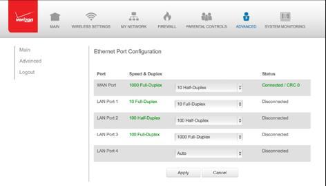
141
142 09/ MONITORING YOUR GATEWAY. 9.0 Gateway Status. 9.1 Advanced Status. 9.2 System Logging. 9.3 Full Status/System wide Monitoring of Connections. 9.4 Traffic Monitoring. 9.5 Bandwidth Monitoring System Monitoring displays system information, including basic settings, system log, key network device parameters and network traffic statistics. GATEWAY STATUS AND ADVANCED STATUS

143 9.0/ GATEWAY STATUS You can view the basic settings of your Gateway. To view the basic settings: 1. Select System Monitoring in the Main menu. The Router Status page displays. 2. To refresh the page, click Refresh. 3. To continuously refresh the page, click Automatic Refresh On. 9.1/ ADVANCED STATUS You can view the details and status of:
144 System Logging Full Status/System wide Monitoring of Connections Traffic Monitoring Broadband Monitoring To view the advanced status: 1. Select Advanced Status. A warning page displays. 2. Click Yes. The Advanced Status page displays. 3. To view the details of the listed monitoring options, click the link. SYSTEM LOGGING AND FULL STATUS/ SYSTEM WIDE MONITORING OF CONNECTIONS 9.2/ SYSTEM LOGGING System logging provides a view of the most recent activity of your Gateway. In addition, you can view additional logs, such as the security, advanced, firewall, WAN, DHCP, and LAN DHCP. To view the system log: 1. In the Advanced Status page, click the System Logging link. 2. To view a specific type of log event such as Security Log, WAN DHCP Log, etc., click the appropriate link in the menu in the left column. 3. To update the data, click Refresh.
145 1. In the Advanced Status page, click Full Status/System wide Monitoring of Connections. 2. To modify the connection properties, click the individual connection links. 9.3/ FULL STATUS/SYSTEM WIDE MONITORING OF CONNECTIONS You can view a summary of the monitored data collected for your Gateway. To view your Gateway s full system status: TRAFFIC MONITORING AND BANDWIDTH MONITORING 3. To refresh the page, click Refresh. 4. To continuously refresh the page, click Automatic Refresh On. 9.4/ TRAFFIC MONITORING Your Gateway continually monitors traffic in the local area network and between the local network and the Internet. You can view up to the second statistical information about data received from and transmitted to the Internet as well as data received from and transmitted to computers in the local network. To view the traffic monitoring data: 1. In the Advanced Status page, select Traffic Monitoring.

146 2. To refresh the page, click Refresh. 3. To continuously refresh the page, click Automatic Refresh On. 9.5/ BANDWIDTH MONITORING You can view and monitor the recorded bandwidth usage measured in Kbps. To view the bandwidth: In the Advanced Status page, select Bandwidth Monitoring.
Fios Quantum Gateway USER GUIDE. Model Fios-G Verizon Wireless
 Fios Quantum Gateway USER GUIDE Model Fios-G1100 2018 Verizon Wireless CONTENTS 01/ INTRODUCTION 1.0 Package 7 Contents 1.1 System 7 Requirements 1.2 Features 7 1.3 Getting to 10 Know Your Gateway 02/
Linksys E2000 Advanced Wireless-N Router. User Guide
 User Guide Table of Contents Contents Chapter 1: Product Overview 1 Top....................................................... 1 Back...................................................... 1 Horizontal
Security SSID Selection: Broadcast SSID:
 69 Security SSID Selection: Broadcast SSID: WMM: Encryption: Select the SSID that the security settings will apply to. If Disabled, then the device will not be broadcasting the SSID. Therefore it will
User Manual. AC ac Wireless Access Point/Router. Model WAC124. NETGEAR, Inc.
 AC2000 802.11ac Wireless Access Point/Router Model WAC124 December 2018 202-11885-02 NETGEAR, Inc. 350 E. Plumeria Drive San Jose, CA 95134, USA AC2000 802.11ac Support Thank you for purchasing this NETGEAR
1. Press "Speed Test" to find out your actual uplink and downlink speed.
 ASRock G10 Gaming Router 6.4 QoS Settings QoS Add Gaming Boost web page. Gaming Boost: Enable or disable the Gaming Boost. Bandwidth The router supports Gaming Boost natively, which identifies and intelligently
User Manual. Rev:
 Default Login Details Login Address: www.mykasda.com Login Password: Set up by users Default Wi-Fi SSID: Kasda xxxx KW6516 (Printed on product label) Default Wi-Fi Password: 12345678 www.kasdanet.com Rev:
User Manual DIR-850L. Wireless AC1200 Dual Band Gigabit Router.
 User Manual DIR-850L Wireless AC1200 Dual Band Gigabit Router USER MANUAL: DIR-850L Wireless AC1200 Dual Band Gigabit Router SYSTEM REQUIREMENTS Network Requirements Web-based Configuration Utility Requirements
Wireless Dual-Band N Router DWRT-600N
 Wireless Dual-Band N Router DWRT-600N User Manual Quality Service Group Product name: Dual-Band N Router (DWRT-600N) Release Date: 2010/9 Manual Revision: V1.0 Web site: Email: www.brickcom.com technical@brickcom.com
AirCruiser G Wireless Router GN-BR01G
 AirCruiser G Wireless Router GN-BR01G User s Guide i Contents Chapter 1 Introduction... 1 Overview...1 Features...1 Package Contents...2 AirCruiser G Wireless Router Rear Panel...2 AirCruiser G Wireless
Wireless-G Router User s Guide
 Wireless-G Router User s Guide 1 Table of Contents Chapter 1: Introduction Installing Your Router System Requirements Installation Instructions Chapter 2: Preparing Your Network Preparing Your Network
Section 3 - Configuration. Enable Auto Channel Scan:
 Enable Auto Channel Scan: Wireless Channel: The Auto Channel Scan setting can be selected to allow the DGL-4500 to choose the channel with the least amount of interference. Indicates the channel setting
User Guide MAX-STREAM AC1750 MU-MIMO GIGABIT ROUTER. Model # EA7300
 User Guide MAX-STREAM AC1750 MU-MIMO GIGABIT ROUTER Model # EA7300 Contents Product Overview...3 Top view... 3 Back view... 4 Setting Up: Basics...6 Where to find more help... 6 How to install your router...
Version /01/2013. User Manual. DAP-1665 Wireless AC1200 Dual Band Access Point DAP-1665
 Version 1.0 10/01/2013 User Manual DAP-1665 Wireless AC1200 Dual Band Access Point DAP-1665 Table of Contents Product Overview... 4 Package Contents... 4 System Requirements... 5 Introduction... 6 Features...
MIMO Wireless Broadband Route r User s Manual 1
 MIMO Wireless Broadband Router User s Manual 1 Introduction...4 Features...4 Minimum Requirements...4 Package Content...4 Note...4 Get to know the Broadband Router...5 Back Panel...5 Front Panel...6 Setup
User Guide. Linksys X-Series. Wireless Router with ADSL2+ Modem
 User Guide Linksys X-Series Wireless Router with ADSL2+ Modem Contents Contents Product Overview X1000..................................... 1 Top 1 Back 1 Wall-mounting placement 2 X3500.....................................
Linksys SMART Wi-Fi Router with Wireless-AC. User Guide
 Linksys SMART Wi-Fi Router with Wireless-AC User Guide Table of Contents Table of Contents Product Overview EA6300.....................................1 Wall-mounting placement 2 Setting Up Your EA-Series
Wireless Broadband Router
 LW6005A-R2 Wireless Broadband Router Manual 1 Introduction... 4 Features... 4 Minimum Requirements... 4 Package Content... 4 Note... 4 Get to know the Broadband Router... 5 Back Panel... 5 Front Panel...
WF-2402 Quick Installation Guide
 WF-2402 Quick Installation Guide Netis 150Mbps Wireless-N Broadband Router 1. Check Your Package Contents The following items should be found in your package: 150Mbps Wireless-N Broadband Router Power
User Guide. 450Mbps/300Mbps Wireless N Access Point TL-WA901ND/TL-WA801ND REV
 User Guide 450Mbps/300Mbps Wireless N Access Point TL-WA901ND/TL-WA801ND REV4.0.0 1910011930 Contents About This Guide...1 Chapter 1. Get to Know About Your Access Point.................... 2 1. 1. Product
Wireless-G Broadband Router with SpeedBooster
 USER GUIDE Wireless-G Broadband Router with SpeedBooster Model: WRT54GS2 About This Guide About This Guide Icon Descriptions While reading through the User Guide you may see various icons that call attention
Wireless b/g/n 150Mbps AP Router
 Wireless 802.11b/g/n 150Mbps AP Router User Manual V1.2 2009-11-30 Package Contents The following items should be found in your package: One Wireless 802.11b/g/n 150Mbps Broadband Router One DC 9v power
Premiertek AP Mbps Wireless-N Broadband Router Quick Installation Guide
 Premiertek AP2402 150Mbps Wireless-N Broadband Router Quick Installation Guide V1.0.8.11 1. Check Your Package Contents The following items should be found in your package: 150Mbps Wireless-N Broadband
JNR1010v2 N150 Wireless Router User Manual
 User Manual January 2014 202-11340-02 350 East Plumeria Drive San Jose, CA 95134 USA Support Thank you for selecting NETGEAR products. After installing your device, locate the serial number on the label
802.11ac Wireless Access Point Model WAC104
 Point Model WAC104 User Manual October 2016 202-11698-01 350 E. Plumeria Drive San Jose, CA 95134 USA Support Thank you for purchasing this NETGEAR product. You can visit www.netgear.com/support to register
WHR-300HP2 / WHR-600D User Manual
 AirStation WHR-300HP2 / WHR-600D User Manual www.buffalotech.com 35020160-03 2015.04 Contents Chapter 1 - Product Overview...6 Package Contents...6 Diagrams and Layout...6 Front Panel...6 Back Panel...8
User s Guide. High Power Wireless-N 600mW Gigabit Dual Band Repeater
 User s Guide High Power Wireless-N 600mW Gigabit Dual Band Repeater CONTENTS GETTING STARTED... 1 Package Contents... 1 LED Indicators... 2 Back Panel Description... 3 SETUP GUIDE... 4 Welcome to the Smart
WL-5420AP. User s Guide
 WL-5420AP User s Guide Table of contents INTRODUCTION... 1 About the Operation Modes...2 LED Indicators...5 Solid...5 Ports on the Rear Panel...7 GETTING CONNECTED... 8 WPA AP -CONFIGURATION VIA WEB...
802.11N Wireless Broadband Router
 802.11N Wireless Broadband Router Pre-N Wireless Access Point Broadband Internet Access WPS 4-Port Switching Hub User's Guide Table of Contents CHAPTER 1 INTRODUCTION... 1 Wireless Router Features... 1
AC750 Wireless Dual-Band Router CR2. User Manual
 AC750 Wireless Dual-Band Router CR2 User Manual Version 1.0 4/25/2014 Table of Content Chapter 1 Introduction... 3 1.1 Features... 3 1.2 System Requirement... 3 1.3 Package Contents... 4 Chapter 2 Hardware
Wireless Router. Model # R3000. User Guide v1
 Wireless Router Model # R3000 User Guide v1 Table of Contents Introduction 1 Minimum System Requirements 1 Features 1 Getting to Know the R3000 3 Performing a Quick Setup 7 Accessing Quick Setup Screens
Change NETGEAR USB Control Center Settings
 Change NETGEAR USB Control Center Settings You can stop the NETGEAR USB Control Center from starting automatically when you log in to Windows. You can also change the language and specify the time-out
USER GUIDE. Wireless-G Broadband Router. Model No: WRT54G2
 USER GUIDE Wireless-G Broadband Router Model No: WRT54G2 About This Guide About This Guide Icon Descriptions While reading through the User Guide you may see various icons that call attention to specific
Copyright and Trademarks. How to Use this Guide. Wireless-G Broadband Router with 2 Phone Ports
 Copyright and Trademarks Specifications are subject to change without notice. Linksys is a registered trademark or trademark of Cisco Systems, Inc. and/or its affiliates in the U.S. and certain other countries.
Introduction... 3 Features... 3 Minimum Requirements... 3 Package Content... 3 Note... 3 Get to know the Broadband Router... 4 Back Panel...
 Introduction... 3 Features... 3 Minimum Requirements... 3 Package Content... 3 Note... 3 Get to know the Broadband Router... 4 Back Panel... 4 Front Panel... 5 Setup Diagram... 6 Getting started... 7 Chapter
GHz 2, g. Wireless-G. Router for Mobile Broadband WIRELESS. User Guide WRT54G3G-VN. Model No.
 GHz 2,4 802.11g WIRELESS Wireless-G Router for Mobile Broadband User Guide Model No. WRT54G3G-VN Copyright and Trademarks Specifications are subject to change without notice. Linksys is a registered trademark
User Manual. Wireless-N ADSL2+ Modem Router
 User Manual Wireless-N ADSL2+ Modem Router Table of Contents 1. ABOUT THIS GUIDE...3 1.1 Navigation of the User s Guide... 3 2. PRODUCT OVERVIEW...3 2.1 Introduction... 3 2.2 Features... 3 2.3 Panel Layout...
AplombTech Smart Router Manual
 AplombTech Smart Router Manual (Version: 1.0) 1 Version & Purpose Version Manual version V 1.0 Explanation Corresponds to the initial version of device Purpose This manual describes the function features
Hardware overview. Package contents V-M200, documentation, three antennas, and power supply.
 The HP V-M200 is a Wi-Fi Alliance authorized Wi-Fi CERTIFIED 802.11a/b/g and 802.11n product. The Wi-Fi CERTIFIED Logo is a certification mark of the Wi-Fi Alliance. In HP V-M200 802.11n Access Point Quickstart
A Division of Cisco Systems, Inc. Wireless-G. Travel Router with SpeedBooster. User Guide WIRELESS WTR54GS. Model No.
 A Division of Cisco Systems, Inc. WIRELESS Wireless-G Travel Router with SpeedBooster User Guide Model No. WTR54GS Copyright and Trademarks Specifications are subject to change without notice. Linksys
D-Link AirPlus G DWL-G700AP
 TM D-Link AirPlus G DWL-G700AP 2.4GHz Wireless Access Point Manual Building Networks for People Contents Package Contents...3 Introduction...4 Wireless Basics...6 Getting Started...8 Using the Configuration
8-Port Gigabit Ethernet Smart Managed Plus Switch with Integrated Cable Management User Manual
 8-Port Gigabit Ethernet Smart Managed Plus Switch with Integrated Cable Management User Manual Model GS908E November 2017 202-11807-02 350 E. Plumeria Drive San Jose, CA 95134 USA Support Thank you for
WRE2206. User s Guide. Quick Start Guide. Wireless N300 Range Extender. Default Details. Version 1.00 Edition 1, 01/2015
 WRE2206 Wireless N300 Range Extender Version 1.00 Edition 1, 01/2015 Quick Start Guide User s Guide Default Details Web Address http://zyxelsetup OR http://192.168.1.2 www.zyxel.com User Name admin Password
Introduction... 3 Features... 3 Minimum Requirements... 3 Package Content... 3 Note... 3 Get to know the Broadband Router... 4 Back Panel...
 Introduction... 3 Features... 3 Minimum Requirements... 3 Package Content... 3 Note... 3 Get to know the Broadband Router... 4 Back Panel... 4 Front Panel... 5 Setup Diagram... 6 Getting started... 7 Chapter
User Manual. TOTOLINK Wireless-N Portable AP
 User Manual TOTOLINK Wireless-N Portable AP TABLE OF CONTENTS 1. ABOUT THIS GUIDE... 3 1.1 Navigation of the User s Guide... 3 2. PRODUCT OVERVIEW... 3 2.1 Introduction... 3 2.2 Features... 3 2.3 Panel
USER GUIDE. Wireless-G Broadband Router with SpeedBooster. Model No: WRT54GS
 USER GUIDE Wireless-G Broadband Router with SpeedBooster Model No: WRT54GS About This Guide About This Guide Icon Descriptions While reading through the User Guide you may see various icons that call attention
LP-2396K Outdoor 2.4GHz Wireless AP/CPE/Bridge
 User Manual LP-2396K Outdoor 2.4GHz Wireless AP/CPE/Bridge 1 Table of Contents 1. Introduction... 3 1.1 Product Introduction... 4 1.2 Package Content... 5 1.3 Product Features... 6 1.4 Application... 6
Content 1 OVERVIEW HARDWARE DESCRIPTION HARDWARE INSTALLATION PC CONFIGURATION GUIDE... 5 WEB-BASED MANAGEMENT GUIDE...
 Content 1 OVERVIEW...1 1.1FEATURES...1 1.2 PACKETCONTENTS...3 1.3 SYSTEM REQUIREMENTS... 1.4 FACTORY DEFAULTS...4 1.5 WARNINGS AND CAUTIONS...4 2 HARDWARE DESCRIPTION... 6 3 HARDWARE INSTALLATION...8 4
User Manual. OT-1044ns
 User Manual OT-1044ns CONTENTS Chapter 1 Introduction... 3 1.1 Features... 3 1.2 Environments... 3 1.3 System Requirement... 4 Chapter 2 Hardware Installation... 4 2.1 Led indicators... 4 2.2 Back Panel
8-Port Gigabit Ethernet Smart Managed Plus Switch with Integrated Cable Management User Manual
 8-Port Gigabit Ethernet Smart Managed Plus Switch with Integrated Cable Management User Manual Model GS908E December 2017 202-11807-03 350 E. Plumeria Drive San Jose, CA 95134 USA Support Thank you for
07/ CONFIGURING SECURITY SETTINGS
 SECURITY LOG Malformed packet: Failed parsing a packed has been blocked because it is malformed. Maximum security enabled service a packet has been accepted because it belongs to a permitted service in
User Guide Model Number RAC2V1A ac Wave 2 Router
 User Guide Model Number RAC2V1A 802.11ac Wave 2 Router 2V1A Router User Guide 1 Table of Contents 1. Overview... 5 1.1. Introduction... 5 2. Product Overview... 6 2.1. About The Router... 6 2.2. What's
ESR300H / ESR150H V N X-TRA RANGE Wireless Router. [ pg. 1]
![ESR300H / ESR150H V N X-TRA RANGE Wireless Router. [ pg. 1]](/thumbs/76/73811912.jpg "ESR300H / ESR150H V N X-TRA RANGE Wireless Router. [ pg. 1]") ESR300H / ESR150H 11N X-TRA RANGE Wireless Router V1.0 [ pg. 1] Table of Contents 1. Product Overview... 5 1.1. Package Contents... 6 1.2. Product Layout... 6 1.3. Wall Mounting... 8 2. Installation...
ESR300H / ESR150H 11N X-TRA RANGE Wireless Router V1.0 [ pg. 1] Table of Contents 1. Product Overview... 5 1.1. Package Contents... 6 1.2. Product Layout... 6 1.3. Wall Mounting... 8 2. Installation...
IP806GA/GB Wireless ADSL Router
 IP806GA/GB Wireless ADSL Router 802.11g/802.11b Wireless Access Point ADSL Modem NAT Router 4-Port Switching Hub User's Guide Table of Contents CHAPTER 1 INTRODUCTION... 1 Wireless ADSL Router Features...
GHz 2, g. Wireless-G. User Guide. ADSL Home Gateway WIRELESS WAG200G (EU) Model No.
 Model No.") GHz 2,4 802.11g WIRELESS Wireless-G ADSL Home Gateway User Guide Model No. WAG200G (EU) Copyright and Trademarks Specifications are subject to change without notice. Linksys is a registered trademark or
GHz 2,4 802.11g WIRELESS Wireless-G ADSL Home Gateway User Guide Model No. WAG200G (EU) Copyright and Trademarks Specifications are subject to change without notice. Linksys is a registered trademark or
Computer to Network Connection
 Computer to Network Connection Network Installation Steps Having a clear understanding of all the steps required to physically building a network improves the success of a project. You may need to install
LevelOne WBR User s Manual. 11g Wireless ADSL VPN Router. Ver
 LevelOne WBR-3407 11g Wireless ADSL VPN Router User s Manual Ver 1.00-0510 Table of Contents CHAPTER 1 INTRODUCTION... 1 Wireless ADSL Router Features... 1 Package Contents... 5 Physical Details... 6 CHAPTER
Dual-Band Wireless-N Gigabit Router
 USER GUIDE Dual-Band Wireless-N Gigabit Router Model: WRT320N About This Guide About This Guide Icon Descriptions While reading through the User Guide you may see various icons that call attention to specific
Broadband Router. User s Manual
 Broadband Router User s Manual 1 Introduction... 4 Features... 4 Minimum Requirements... 4 Package Content... 4 Note... 4 Get to know the Broadband Router... 5 Back Panel... 5 Front Panel... 6 Setup Diagram...7
USER GUIDE. Wireless-G Broadband Router. Model No: WRT54G2 V1
 USER GUIDE Wireless-G Broadband Router Model No: WRT54G2 V1 About This Guide About This Guide Icon Descriptions While reading through the User Guide you may see various icons that call attention to specific
User s Guide HIGHPOWERTM AC2600 WI-FI RANGE EXTENDER REC44M
 User s Guide HIGHPOWERTM AC2600 WI-FI RANGE EXTENDER REC44M CONTENTS INTRODUCTION... 2 GETTING STARTED... 3 Package Contents... 3 LED Indicators, Ports and Buttons... 4 SETUP GUIDE... 5 Find a Setup Location...
TRENDnet User s Guide. Cover Page
 Cover Page Table of Contents Product Overview... 4 Package Contents... 4 Features... 4 Product Hardware Features... 5 Application Diagram... 6 Basic Router Setup... 7 Creating a Home Network... 7 Router
High Power Wireless N. 600mW Smart Repeater LP 9698SR
 High Power Wireless N 600mW Smart Repeater LP 9698SR INTRODUCTION...4 GETTING STARTED...5 Package Contents...5 LED Indicators...6 Back Panel Description...7 SETUP GUIDE...8 Find a Setup Location...8 Connect
EnGenius EAP N Multi-Function AP/Repeater
 EnGenius EAP9550 11N Multi-Function AP/Repeater Table of Content 1. Introduction...4 1.1. Features and Benefits...4 1.2. Package Contents...5 1.3. System Requirement...5 2. Understanding the Hardware...6
Wireless-N Gigabit Router
 USER GUIDE Model: WRT310N About This Guide About This Guide Icon Descriptions While reading through the User Guide you may see various icons that call attention to specific items. Below is a description
WL5041 Router User Manual
 TECOM WL5041 Router User Manual TECOM CO., LTD. March 2003 2003 by TECOM CO., LTD. All rights reserved. Printed in Taiwan Table of contents Package Contents--------------------------------------- 2 Installing
Table of Contents. Table of Contents
 Table of Contents Table of Contents Product Overview...4 Package Contents... 4 System Requirements... 4 Features... 5 Hardware Overview... 6 Connections... 6 LEDs... 7 Wireless Installation Considerations...
Chapter 1 Introduction
 Copyright Statement is the registered trademark of Zonet Technology Inc. All the products and product names mentioned herein are the trademarks or registered trademarks of their respective holders. Copyright
Version /08/2016. User Manual. Mobile Wi-Fi Hotspot 21 Mbps DWR-730
 Version 3.00 06/08/2016 User Manual Mobile Wi-Fi Hotspot 21 Mbps DWR-730 Preface D-Link reserves the right to revise this publication and to make changes in the content hereof without obligation to notify
Linksys EA-Series Routers
 Routers Table of Contents Table of Contents Product overview EA2700/EA3500 Back view Bottom view EA4500 Top view Back view Setting Up Your EA-Series Router Where to find more help How to set up your router
Wireless-N Broadband Router
 USER GUIDE Model: WRT160N About This Guide About This Guide Icon Descriptions While reading through the User Guide you may see various icons that call attention to specific items. Below is a description
A5500 Configuration Guide
 A5500 Configuration Guide Sri Ram Kishore February 2012 Table of contents Gateway Configuration... 3 Accessing your gateway configuration tool... 3 Configuring your broadband Internet access... 3 Configuring
Version 1.00 May 02, User Manual. Wi-Fi AC600 Dual Band Mini Router DIR-516
 Version 1.00 May 02, 2014 User Manual Wi-Fi AC600 Dual Band Mini Router DIR-516 Preface D-Link reserves the right to revise this publication and to make changes in the content hereof without obligation
Table of Contents. Page ii
 Table of Contents Chapter 1 Introduction 1 Features... 1 Safety Instructions... 1 Package Contents... 2 Physical Details... 3 Chapter 2 Setup 5 Overview... 5 Using the Windows Wizard... 5 Chapter 3 Web-Based
User Manual HIGHPOWER TM TOUCH SCREEN WI-FI RANGE EXTENDER S1
 User Manual HIGHPOWER TM TOUCH SCREEN WI-FI RANGE EXTENDER S1 1 Table of Contents INTRODUCTION...4 Product view...4 Package Contents...5 Product Description...5 SETUP GUIDE (TOUCH SCREEN)...6 Find a Setup
DWR G Integrated Access Device. User Manual
 DWR-923 4G Integrated Access Device User Manual TABLE OF CONTENTS 1. GETTING TO KNOW THE DWR-923... 2 1.1 Introduction... 2 1.2 Package Contents... 3 1.3 System Requirements... 3 1.4 Hardware Overview
N900 Wireless Dual Band Gigabit Router
 Trademarks NETGEAR, the NETGEAR logo, and Connect with Innovation are trademarks and/or registered trademarks of NETGEAR, Inc. and/or its subsidiaries in the United States and/or other countries. Information
AC1600 Wireless Dual Band Gigabit VoIP VDSL/ADSL Modem Router
 AC1600 Wireless Dual Band Gigabit VoIP VDSL/ADSL Modem Router Powerful Wi-Fi and Gigabit Wired for a High-Speed Home 300Mbps + 1300Mbps Dual Band Wi-Fi Gigabit Ports VoIP (2 FXS ports) Beamforming Technology
Linksys SMART Wi-Fi Routers with Wireless-AC. User Guide
 Linksys SMART Wi-Fi Routers with Wireless-AC User Guide Table of Contents Table of Contents Product Overview Troubleshooting EA6300.....................................1 EA6400/EA6700...............................
802.11N Wireless ADSL Router
 802.11N Wireless ADSL Router Pre-N Wireless Access Point ADSL Modem NAT Router WPS 4-Port Switching Hub User's Guide Table of Contents CHAPTER 1 INTRODUCTION...1 Wireless ADSL Router Features...1 Package
TRENDnet User s Guide Table of Contents
 Table of Contents i Table of Contents Contents Product Overview... 3 Package Contents... 3 Features... 3 Product Hardware Features... 4 Application Diagram... 6 Basic Router Setup... 6 Creating a Home
DRG600-WIFI USER GUIDE
 DRG600-WIFI USER GUIDE P/N: DFB601CW Copyright 2008. All Rights Reserved. Printed May 15, 2008 All trademarks and trade names are the properties of their respective owners. Page 2 of 104 Contents INTRODUCTION...
RangePlus Wireless Router
 USER GUIDE Model: WRT110 About This Guide About This Guide Icon Descriptions While reading through the User Guide you may encounter various icons designed to call attention to a specific item. Below is
GHz. Wireless-G. Broadband Router with 2 Phone Ports. Voice. User Guide WRTP54G (EU/LA) Model No.
 Model No.") GHz 2,4 802.11g Voice Model No. Wireless-G Broadband Router with 2 Phone Ports WRTP54G (EU/LA) User Guide Copyright and Trademarks Specifications are subject to change without notice. Linksys is a registered
GHz 2,4 802.11g Voice Model No. Wireless-G Broadband Router with 2 Phone Ports WRTP54G (EU/LA) User Guide Copyright and Trademarks Specifications are subject to change without notice. Linksys is a registered
WAP3205 v2. User s Guide. Quick Start Guide. Wireless N300 Access Point. Default Login Details. Version 1.00 Edition 2, 12/2012
 WAP3205 v2 Wireless N300 Access Point Version 1.00 Edition 2, 12/2012 Quick Start Guide User s Guide Default Login Details LAN IP Address http://192.168.1.2 Password 1234 www.zyxel.com Copyright 2012 ZyXEL
AC1200. Dual-band OpenWRT WiFi Router KW6515. Highlights. High Speed 300Mbps on 2.4GHz + 900Mbps on 5GHz totals 1200Mbps Wi-Fi
 AC1200 Dual-band OpenWRT WiFi Router KW6515 Highlights High Speed 300Mbps on 2.4GHz + 900Mbps on 5GHz totals 1200Mbps Wi-Fi speeds,avoids interference, ensuring top Wi-Fi speed and stable connections Maximum
User Guide VELOP. Whole Home Wi-Fi. Model WHW03
 User Guide VELOP Whole Home Wi-Fi Model WHW03 Contents Product Overview...3 Front/Top view... 3 Bottom view... 4 Setting Up: Basics...5 Where to find more help... 5 How to install your Velop... 5 How to
User s Guide RTA2600 ATHENA HIGHPOWER AC2600 WI-FI ROUTER MU-MIMO
 User s Guide RTA2600 ATHENA HIGHPOWER AC2600 WITH WI-FI ROUTER MU-MIMO TM CONTENTS INTRODUCTION... 3 GETTING STARTED... 4 Package Contents... 4 LED Indicators... 5 Back Panel Description... 7 BASIC SETUP
Wireless LAN Access Point
 Wireless LAN Access Point IEEE 802.11b 11Mbps User s Manual Table of Contents Chapter 1 Introduction... 1 1.1 Package Contents... 2 1.2 Features... 2 1.3 Specifications... 2 1.4 Physical Description...
User Manual WCR-HP-GN AirStation N Technology HighPower Wireless N150 Router, Access Point, & Bridge
 User Manual WCR-HP-GN AirStation N Technology HighPower Wireless N150 Router, Access Point, & Bridge www.buffalotech.com 35011715 ver.01 Contents Chapter 1 - Product Overview...5 Features... 5 Air Navigator
Nighthawk X4S AC2600 Smart WiFi Router Model R7800. Package Contents. NETGEAR, Inc. 350 East Plumeria Drive San Jose, CA USA.
 Support Thank you for purchasing this NETGEAR product. You can visit www.netgear.com/support to register your product, get help, access the latest downloads and user manuals, and join our community. We
Wireless USB Port Multi-Functional Printer Server. Model # AMPS240W. User s Manual. Ver. 1A
 Wireless USB 2.0 1-Port Multi-Functional Printer Server Model # AMPS240W User s Manual Ver. 1A Table of Contents 1 Introduction...3 1.1 Package Contents... 3 1.2 System Requirements... 3 2 Multi-Functional
Nighthawk X6S AC3000 Tri-Band WiFi Router User Manual
 Nighthawk X6S AC3000 Tri-Band WiFi Router User Manual Model R7900P May 2017 202-11719-01 350 E. Plumeria Drive San Jose, CA 95134 USA Support Thank you for purchasing this NETGEAR product. You can visit
Covr your whole home in Seamless Wi-Fi
 Covr your whole home in Seamless Wi-Fi High Performance More Coverage One Seamless Network TRI-BAND WHOLE HOME WI-FI SYSTEM COVR-2202/2200 USER MANUAL Preface D-Link reserves the right to revise this publication
RX3041. User's Manual
 RX3041 User's Manual Table of Contents 1 Introduction... 2 1.1 Features and Benefits... 3 1.2 Package Contents... 3 1.3 Finding Your Way Around... 4 1.4 System Requirements... 6 1.5 Installation Instruction...
LevelOne FBR User s Manual. 1W, 4L 10/100 Mbps ADSL Router. Ver
 LevelOne FBR-1416 1W, 4L 10/100 Mbps ADSL Router User s Manual Ver 1.00-0510 Table of Contents CHAPTER 1 INTRODUCTION... 1 FBR-1416 Features... 1 Package Contents... 3 Physical Details... 3 CHAPTER 2
User s Guide HIGHPOWERTM WI-FI RANGE EXTENDER REC22A AC1200
 User s Guide REC22A HIGHPOWERTM AC1200 WI-FI RANGE EXTENDER CONTENTS INTRODUCTION... 2 GETTING STARTED... 3 Package Contents... 3 LED Indicators, Ports and Buttons... 4 SETUP GUIDE... 5 Find a Setup Location...
A+ Certification Guide. Chapter 16 (Part B) Networking
 Networking") A+ Certification Guide Chapter 16 (Part B) Networking Chapter 16 (Part B) Objectives Installing and Configuring Network Interface Cards Networking Configuration for Small Network Switches and Routers Setting
A+ Certification Guide Chapter 16 (Part B) Networking Chapter 16 (Part B) Objectives Installing and Configuring Network Interface Cards Networking Configuration for Small Network Switches and Routers Setting
EMG2926-Q10A Quick Start Guide User s Guide Default Login Details
 EMG2926-Q10A Dual-Band Wireless AC/N Gigabit Ethernet Gateway Version 1.00 Edition 2, 08/2015 Quick Start Guide User s Guide Default Login Details LAN IP Address http://192.168.0.1 (Router Mode) User Name
TRENDnet User s Guide. Cover Page
 Cover Page Contents Product Overview... 1 Package Contents... 1 Features... 1 Product Hardware Features... 2 Application Diagram... 4 Basic Router Setup... 5 Creating a Home Network... 5 Router Installation...
A Division of Cisco Systems, Inc. GHz 2, g. Wireless-G. User Guide. Access Point WIRELESS WAP54G (EU/LA/UK) Model No.
 Model No.") A Division of Cisco Systems, Inc. GHz 2,4 802.11g WIRELESS Wireless-G Access Point User Guide Model No. WAP54G (EU/LA/UK) Copyright and Trademarks Specifications are subject to change without notice. Linksys
A Division of Cisco Systems, Inc. GHz 2,4 802.11g WIRELESS Wireless-G Access Point User Guide Model No. WAP54G (EU/LA/UK) Copyright and Trademarks Specifications are subject to change without notice. Linksys