POWER SYSTEMS STUDY: SIGNIFICANT (OR TOTAL) DELETION OF EXISTING TEXT
|
|
|
- Lucy McGee
- 5 years ago
- Views:
Transcription
1 POWER SYSTEMS STUDY: SIGNIFICANT (OR TOTAL) DELETION OF EXISTING TEXT Delete the following current section in its entirety (deletions are shown struck through)..01 General A. Short circuit Studies, Protective Device Evaluation Studies, Protective Device Coordination Studies and Flash Protection Studies shall be performed by the distribution equipment manufacturer or an independent firm currently involved in high and low voltage power system evaluation. The study shall be performed, stamped and signed by a registered professional engineer in the State of Pennsylvania. Credentials of the individual(s) performing the study and the background of the firm shall be submitted to the Engineer for approval prior to start of the work. A minimum of five (5) years experience in power system analysis is required for the individual in charge of the project. B. The studies shall be submitted to Engineering Services prior to receiving final approval of the distribution equipment shop drawings and prior to release of equipment for manufacture. If formal completion of the studies may cause delay in equipment manufacture, approval from Engineering Services may be obtained for a preliminary submittal of sufficient study data to ensure that the selection of device ratings and characteristics will be satisfactory. C. The studies shall include all portions of the electrical distribution system from the normal power incoming primary source or sources, the emergency and standby power source or sources, down to and including all panels and distribution equipment in the distribution system, and as required to comply with NFPA 70E. Normal system connections and those which result in maximum fault and/or arc flash conditions, shall be adequately covered in the study. D. The firm performing the study shall demonstrate capability and experience to provide assistance during start up, as required. E. The power system studies are required to confirm the adequacy of the ratings of all electrical system components and proper coordination settings of all circuit breakers. These studies shall not be used as a basis to compromise the electrical system and do not imply that short circuit ratings of distribution equipment and devices may be lower than those indicated on the drawings or specified herein. F. The power distribution equipment manufacturer shall carry in their bid to the Electrical Subcontractor, a sufficient allowance to provide modifications to the equipment, if necessary, based on the results of the studies identified herein. G. Perform all studies using SKM Systems Analysis software. H. Submit an electronic copy of the final study in the format used to perform the study..02 Coordination Study
2 A. Perform coordination study to support the selection of instrument transformer ratios, protective relay characteristics and settings, fuse ratings, low-voltage circuit breaker ratings, characteristics, and settings. B. The study shall demonstrate that the protective devices as selected and set will ensure that the minimum unfaulted load is interrupted when protective devises isolate a fault or overload anywhere in the system while satisfactory protection is provided for equipment against overloads, and short circuits are interrupted as rapidly as possible. C. Provide technical characteristics, manuals, time characteristic curves, etc. for each protective device along with the calculations used in preparing the study to Engineering Services. Report shall be in paper as well as editable electronic format. Electronic copy shall be SKM Systems Analysis software..03 Fault Current Study A. The short-circuit current available on the primary feeder will be given to the Professional by Engineering Services. B. Calculate the maximum available short-circuit current in amperes rms symmetrical at circuit-breaker positions of the electrical power distribution system. The calculation shall be for a current immediately after initiation and for a three-phase bolted short circuit at each of the following: 1. Switchgear and switchboard bus. 2. Medium-voltage controller. 3. Motor-control center. 4. Distribution panelboard. 5. Branch circuit panelboard. 6. Other equipment as required..04 NFPA 70E (Arc Flash Analysis) Study A. Calculate Arc-Flash Incident Energy (AFIE) levels and flash protection boundary distances. B. The Arc-Flash Hazard Analysis shall be performed in conjunction with a shortcircuit analysis and a time-current coordination analysis. C. Results of the Analysis shall be submitted in tabular form, and shall include device or bus name, bolted fault and arcing fault current levels, flash protection boundary distances, personal-protective equipment classes and AFIE levels. D. The analysis shall be performed under worst-case Arc-Flash conditions, and the final report shall describe, when applicable, how these conditions differ from worst-case bolted fault conditions. E. The Arc-Flash Hazard Analysis shall be performed in compliance with IEEE Standard 1584 (latest edition), the IEEE Guide for Performing Arc-Flash Calculations. F. The Arc-Flash Hazard Analysis shall include recommendations for reducing AFIE levels and enhancing worker safety.
3 G. The Arc-Flash Hazard Analysis shall include the proper settings for arc flash reduction maintenance switch(es), if specified on the project. Provide settings to avoid nuisance tripping. H. The proposed vendor shall demonstrate experience with Arc-Flash Hazard Analysis by submitting names of at least ten actual Arc-Flash Hazard Analyses it has performed in the past year. I. The proposed vendor shall demonstrate capabilities in providing equipment, services, and training to reduce Arc-Flash exposure and train workers in accordance with NFPA 70E and other applicable standards. J. The proposed vendor shall demonstrate experience in providing equipment labels in compliance with NEC-2002 section 110 and ANSI Z535.4 to identify AFIE and appropriate Personal Protective Equipment classes. K. Engineer shall specify or provide study on all major electrical distribution equipment and downstream distribution and utilization equipment. This shall include, but not be limited to: 1. Substation(s), switchgear, and switchboards 2. Distribution panelboards Lighting and appliance panelboards 3. Motor control centers 3. Disconnect switches 3. Controller equipment such as variable frequency/adjustable speed drives 3. Fuses and circuit breakers 3. Rotating equipment 3. Batteries 4. Generator(s) 4. Automatic transfer switches 4. Feeders K. Provide proper labeling per NFPA 70E on all noted equipment, including any hinged doors of rear-accessible equipment. Coordinate study and labeling requirements with Engineering Services. Typical minimum label requirements shown below:

4 Label shall be orange and include the date of the study. Specify a second blue label to note arc-reduction levels, when using arc-flash reduction feature. Require manufacturer representative to provide a letter stating that they have visited the site and confirmed that the stickers have been applied in appropriate locations, per the approved Power System Study. Replace with following text..01 General A. The short-circuit current available on the primary feeder will be given to the Professional by Engineering Services. B. The proposed vendor shall demonstrate capabilities in providing equipment, services, and training to reduce Arc-Flash exposure and train workers in accordance with NFPA 70E and other applicable standards..02 Guide Specifications
5 A. Design Professional shall carefully review and edit the guideline specifications below, adapting them as needed to achieve application-specific, fully developed specifications for each project. B. These shall be edited using the process described in the instructions contained at the beginning of the document. Proposed modifications shall be reviewed with OPP Engineering Services. C. Finalized version shall be included in the project contract documents. Use of other specifications is not acceptable. D. The design professional shall utilize the sample arc flash labels and the content within as a baseline for the arc flash labels that are to be generated from the power study. Document Power Study Guide Specification.docx Power Study Sample Arc Flash Labels PSU Standard Arc Flash Label Sample 1 (PDF) PSU Standard Arc Flash Label Sample 2 (PDF) Version Date June 2016 June 2016 Description University s guide specification for Power Studies of electrical systems; to be used by the design professional. Typical University Standard Arc Flash label for the Professionals use. The details provided are a baseline and it is the responsibility of the professional to design and develop complete labels that are acceptable. END of revision Update Commentary: Section was updated primarily for the following reasons: 1) Deleted old section and replaced with new section, which includes a new guide specification section and sample standard arc flash labels.
6
7 SECTION POWER SYSTEM STUDY Revise this Section by deleting and inserting text to meet Project-specific requirements. This Section uses the term "Architect." Change this term to match that used to identify the design professional as defined in the General and Supplementary Conditions. Verify that Section titles referenced in this Section are correct for this Project's Specifications; Section titles may have changed. General Notes: 1. This guide specification is intended to provide the Design Professional with a basic guideline of minimum OPP requirements. 2. The guide specification shall be carefully reviewed and edited with respect to application-specific project requirements. Proposed modifications shall be reviewed with OPP Staff. 3. Finalized version shall be included in the project contract documents. Editing Notes 1. This OPP Guide specification must only be altered by notation (i.e. deleted text with strikethrough and additional text with double underline). This shall be accomplished by using Tools /Track Changes / Highlight Changes, and select "Track changes while editing" in MS Word or equivalent. 2. The Review Submittal Specification section shall be provided in electronic form for OPP Review. 3. Leave the following Note ("For Construction Document Review, Design Submittal") as part of the Review Submittal, to aid any Reviewer to understand WHY there are strikeouts and underlines. Also, leave any DESIGNER NOTE placed in this Guide Spec. 4. AFTER comments are received from PSU and incorporated, the strikeouts and underlines shall be removed, and the REVIEWER NOTEs deleted, before the spec is issued for Bidding. PART 1 - GENERAL 1.1 RELATED DOCUMENTS Retain or delete this article in all Sections of Project Manual. A. Drawings and general provisions of the Contract, including General and Supplementary Conditions and Division 01 Specification Sections, apply to this Section. B. All sections of the project manual are directly applicable to this specification section. Should a conflict arise between specification sections or between specifications and drawings and/or code requirements, the contractor shall notify the Architect/Engineer of the conflict in writing. If POWER SYSTEMS STUDY
8 direction is not provided prior to the submission of the bid, the contractor shall price the more extensive system. 1.2 SUMMARY A. Section includes computer-based, power systems study with the following sections: 1. Overcurrent protective device coordination study to determine overcurrent protective devices and to determine overcurrent protective device settings for selective tripping. 2. Fault current study to determine the minimum interrupting capacity of circuit protective devices. 3. Arc-Flash study to determine the arc-flash hazard distance and the incident energy to which personnel could be exposed during work on or near electrical equipment. 1.3 DEFINITIONS Retain terms that remain after this Section has been edited for a project. A. Existing to Remain: Existing items of construction that are not to be removed and that are not otherwise indicated to be removed, removed and salvaged, or removed and reinstalled. B. One-Line Diagram: A diagram which shows, by means of single lines and graphic symbols, the course of an electric circuit or system of circuits and the component devices or parts used therein. C. Protective Device: A device that senses when an abnormal current flow exists and then removes the affected portion from the system. D. SCCR: Short-circuit current rating. E. Service: The conductors and equipment for delivering electric energy from the serving utility to the wiring system of the premises served. 1.4 ACTION SUBMITTALS A. Product Data: For computer software program to be used for studies. B. Other Action Submittals: Submittals shall be in digital form. Upload electronic submittals using Owner s web-based file transfer tool 1. Power system study input data, including completed computer program input data sheets. 2. Study and equipment evaluation reports; Signed, dated, and sealed by a qualified professional engineer. a. Submit study report for action prior to receiving final approval of the distribution equipment submittals. If formal completion of studies will cause delay in equipment manufacturing, obtain approval from Owner/Engineer for preliminary submittal of sufficient study data to ensure that the selection of devices and associated characteristics is satisfactory. POWER SYSTEMS STUDY
9 3. Revised single-line diagram, reflecting field investigation results and results of power system study 1.5 INFORMATIONAL SUBMITTALS A. Qualification Data: For [Coordination Study Specialist] [Field Adjusting Agency]. B. Product Certificates: For overcurrent protective device coordination study software (shortcircuit and arc-flash hazard studies), certifying compliance with IEEE 399, IEEE1584, and NFPA 70E. 1.6 CLOSEOUT SUBMITTALS A. Operation and Maintenance Data: For the overcurrent protective devices to include in emergency, operation, and maintenance manuals. 1. Include the following: a. The following parts from the Power System Study Report: 1) One-line diagram in.pdf and.dwg format. 2) Complete power system model in SKM format. a) Provide three (3) hard copies of the system model. b) The contractor is required to provide the study project files to the Owner in electronic format. 3) Time-current coordination curves. b. Power system data. B. Maintenance procedures according to requirements in NFPA 70E shall be provided in equipment manuals. 1.7 QUALITY ASSURANCE A. Coordination Study Specialist Qualifications: Professional engineer in charge of performing the study and documenting recommendations, licensed in the state where Project is located and has a minimum of 5 years experience utilizing the program. All elements of the study shall be performed under the direct supervision and control of this professional engineer. B. Field Adjusting Agency Qualifications: An independent agency, with the experience and capability to adjust overcurrent devices, assist with start-up as required, and to conduct the testing indicated, that is a member company of the InterNational Electrical Testing Association or is a nationally recognized testing laboratory (NRTL) as defined by OSHA in 29 CFR , and that is acceptable to authorities having jurisdiction. POWER SYSTEMS STUDY
10 PART 2 - PRODUCTS 2.1 COMPUTER SOFTWARE DEVELOPERS A. Software Developers: Subject to compliance with requirements, provide software by the following: 1. SKM Systems Analysis, Inc B. Comply with IEEE 242, IEEE 399, IEEE 1584, and NFPA 70E. C. Analytical features of device coordination study computer software program shall have the capability to calculate "mandatory," "very desirable," and "desirable" features as listed in IEEE 399. D. Computer software program shall be capable of plotting and diagramming time-currentcharacteristic curves as part of its output. Computer software program shall report device settings and ratings of all overcurrent protective devices and shall demonstrate selective coordination by computer-generated, time-current coordination plots. 1. Optional Features: a. Arcing faults. b. Simultaneous faults. c. Explicit negative sequence. d. Mutual coupling in zero sequence. 2.2 PROTECTIVE DEVICE COORDINATION STUDY REPORT CONTENTS A. Executive summary shall include deficiencies and recommendations as found by the study. B. Study descriptions, purpose, basis and scope. Include case descriptions, definition of terms and guide for interpretation of the computer printout. C. One-line diagram, showing the following: 1. Protective device designations, ampere ratings, and short-circuit (AIC) rating of equipment. 2. Cable size and lengths. 3. Transformer kilovolt ampere (kva) and voltage ratings. 4. Motor and generator designations and kva ratings. 5. Switchgear, switchboard, motor-control center, and panelboard designations. 6. Available fault current at each piece of equipment. D. Study Input Data: As described in "Power System Data" Article. E. Short-Circuit Study Report: Present information in table format of report summary with nameplate and calculated values and compare with percentages. 1. Protective Device Evaluation: POWER SYSTEMS STUDY
11 a. Evaluate equipment and protective devices and compare to short-circuit ratings. b. Tabulations of circuit breaker, fuse, and other protective device ratings versus calculated short-circuit duties. c. For 600-V overcurrent protective devices, ensure that interrupting ratings are equal to or higher than calculated 1/2 cycle symmetrical fault current. d. For devices and equipment rated for asymmetrical fault current, apply multiplication factors listed in the standards to 1/2 cycle symmetrical fault current. e. Verify adequacy of phase conductors at maximum three-phase bolted fault currents; verify adequacy of equipment grounding conductors and grounding electrode conductors at maximum ground-fault current. 2. Short-Circuit Study Output: a. Low-Voltage Fault Report: Three-phase and unbalanced fault calculations, showing the following for each overcurrent device location: 1) Voltage. 2) Calculated fault-current magnitude and angle. 3) Fault-point X/R ratio. 4) Equivalent impedance. b. Momentary Duty Report: 1) Voltage. 2) Calculated symmetrical fault-current magnitude and angle. 3) Fault-point X/R ratio. 4) Calculated asymmetrical fault current: a) Based on fault-point X/R ratio. b) Based on calculated symmetrical value multiplied by 1.6. c) Based on calculated symmetrical value multiplied by 2.7. c. Interrupting Duty Report: Three-phase and unbalanced fault calculations, showing the following for each overcurrent device location: 1) Voltage. 2) Calculated symmetrical fault-current magnitude and angle. 3) Fault-point X/R ratio. 4) No AC Decrement (NACD) ratio. 5) Equivalent impedance. 6) Multiplying factors for 2-, 3-, 5-, and 8-cycle circuit breakers rated on a symmetrical basis. 7) Multiplying factors for 2-, 3-, 5-, and 8-cycle circuit breakers rated on a total basis. F. Protective Device Coordination Study: 1. Report recommended settings of protective devices, ready to be applied in the field (may be provided in table format). Use manufacturer's data sheets for recording the recommended setting of overcurrent protective devices when available. a. Phase and Ground Relays: POWER SYSTEMS STUDY
12 1) Device tag. 2) Relay current transformer ratio and tap, time dial, and instantaneous pickup value. 3) Recommendations on improved relaying systems, if applicable. b. Circuit Breakers: 1) Adjustable pickups and time delays (long time, short time, ground). 2) Adjustable time-current characteristic. 3) Adjustable instantaneous pickup. 4) Recommendations on improved trip systems, if applicable. Low-voltage fuse classes are defined in UL through UL Medium-voltage fuses are defined in IEEE C c. Fuses: Show current rating, voltage, and class. G. Time-Current Coordination Curves: Determine settings of overcurrent protective devices to achieve selective coordination. Graphically illustrate that adequate time separation exists between devices installed in series, including power utility company's upstream devices. Prepare separate sets of curves for the switching schemes and for emergency periods where the power source is local generation. Show the following information: 1. Device tag and title, one-line diagram with legend identifying the portion of the system covered. 2. Terminate device characteristic curves at a point reflecting maximum symmetrical or asymmetrical fault current to which the device is exposed. 3. Identify the device associated with each curve by manufacturer type, function, and, if applicable, tap, time delay, and instantaneous settings recommended. 4. Plot the following listed characteristic curves, as applicable: a. Power utility's overcurrent protective device. b. Medium-voltage equipment overcurrent relays. c. Medium- and low-voltage fuses including manufacturer's minimum melt, total clearing, tolerance, and damage bands. d. Low-voltage equipment circuit-breaker trip devices, including manufacturer's tolerance bands. e. Transformer full-load current, magnetizing inrush current, and ANSI through-fault protection curves. f. Cables and conductors damage curves. g. Ground-fault protective devices. h. Motor-starting characteristics and motor damage points. i. Generator short-circuit decrement curve and generator damage point. j. The largest feeder circuit breaker in each motor-control center and panelboard. 5. Provide adequate time margins between device characteristics such that selective operation is achieved per IEEE Comments and recommendations for system improvements. H. Arc-Flash Study Output: POWER SYSTEMS STUDY
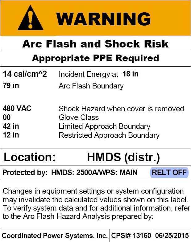
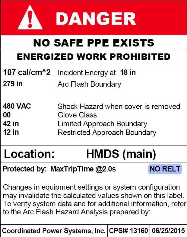
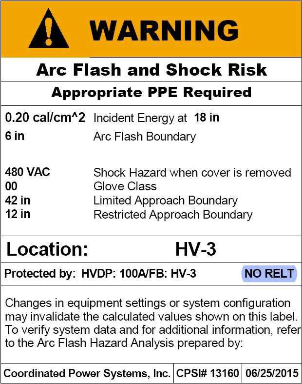
13 1. Interrupting Duty Report: Provide in table format based on measures taken to reduce incident energy. Provide normal, emergency, and reduced energy let-through settings for each device. Three-phase and unbalanced fault calculations, showing the following for each overcurrent device location: a. Voltage. b. Calculated symmetrical fault-current magnitude and angle. c. Fault-point X/R ratio. d. No AC Decrement (NACD) ratio. e. Equivalent impedance. f. Multiplying factors for 2-, 3-, 5-, and 8-cycle circuit breakers rated on a symmetrical basis. Provide worst case value. g. Multiplying factors for 2-, 3-, 5-, and 8-cycle circuit breakers rated on a total basis. Provide worst case value. I. Incident Energy and Flash Protection Boundary Calculations: 1. Arcing fault magnitude. 2. Protective device clearing time. 3. Duration of arc. 4. Arc-flash boundary. 5. Working distance. 6. Incident energy. 7. Hazard risk category. 8. Recommendations for arc-flash energy reduction. J. Fault study input data, case descriptions, and fault-current calculations including a definition of terms and guide for interpretation of the computer printout. 2.3 ARC-FLASH WARNING LABELS A. Comply with requirements in Section "Identification for Electrical Systems." Produce a 3.5-by-5-inch thermal transfer label of high-adhesion polyester for each work location included in the analysis. B. The label shall have an orange header with the wording, "WARNING, ARC-FLASH HAZARD," and shall include the following information taken directly from the arc-flash hazard analysis: 1. Location designation and fed from location 2. Nominal voltage. 3. Flash protection boundary (Restricted and Limited). 4. Incident energy. 5. Working distance. 6. Engineering report number, Engineering Company Name, revision number, and issue date. C. Labels shall be machine printed, with no field-applied markings. POWER SYSTEMS STUDY
14 1. For equipment with separate maintenance mode settings, a separate Arc Flash label shall be installed. Maintenance mode labels shall be printed in blue. 2. Equipment with incident energy levels above 40 cal, a red Danger label shall be installed per requirements in Section Identification for Electrical Systems. PART 3 - EXECUTION 3.1 EXAMINATION This article lists data needed to conduct the study. Delete data already shown on the one-line diagram; add data that should be considered in the study results. A. Obtain all data necessary for the conduct of the study. 1. Verify completeness of data supplied on the one-line diagram. Call any discrepancies to the attention of Owner. 2. For equipment provided that is Work of this Project, use characteristics submitted under the provisions of action submittals and information submittals for this Project. 3. For [relocated ]equipment [and ]that [which ]is existing to remain, obtain required electrical distribution system data by field investigation and surveys, conducted by qualified technicians and engineers. The qualifications of technicians and engineers shall be qualified as defined by NFPA 70E. B. Gather and tabulate the following input data to support the short-circuit study. Comply with recommendations in IEEE 551 as to the amount of detail that is required to be acquired in the field. Field data gathering shall be under the direct supervision and control of the engineer in charge of performing the study, and shall be by the engineer or its representative who holds NETA ETT Level III certification or NICET Electrical Power Testing Level III certification approved by owner. 1. Product Data for Project's overcurrent protective devices involved in overcurrent protective device coordination studies. Use equipment designation tags that are consistent with electrical distribution system diagrams, overcurrent protective device submittals, input and output data, and recommended device settings. 2. Obtain electrical power utility impedance at the service. 3. Power sources and ties. 4. Full-load current of all loads. 5. Voltage level at each bus. 6. For transformers, include kva, primary and secondary voltages, connection type, impedance, X/R ratio, taps measured in percent, and phase shift. 7. For circuit breakers and fuses, provide manufacturer and model designation. List type of breaker, type of trip, SCCR, current rating, and breaker settings. 8. Generator short-circuit current contribution data, including short-circuit reactance, rated kva, rated voltage, and X/R ratio. 9. Busway manufacturer and model designation, current rating, impedance, lengths, and conductor material. 10. Motor horsepower and NEMA MG 1 code letter designation. 11. Low-voltage cable sizes, lengths, number, conductor material, and conduit material (magnetic or nonmagnetic). POWER SYSTEMS STUDY
15 12. Medium-voltage cable sizes, lengths, conductor material, and cable construction and metallic shield performance parameters. C. Examine Project overcurrent protective device submittals for compliance with electrical distribution system coordination requirements and other conditions affecting performance. Devices to be coordinated are indicated on Drawings. 1. Proceed with coordination study only after relevant equipment submittals have been assembled. Overcurrent protective devices that have not been submitted and approved prior to coordination study may not be used in study. 3.2 LOAD-FLOW AND VOLTAGE-DROP STUDY A. Perform a load-flow and voltage-drop study to determine the steady-state loading profile of the system. Analyze power system performance two times as follows: 1. Determine load-flow and voltage drop based on full-load currents obtained in "Power System Data" Article. 2. Determine load-flow and voltage drop based on 80 percent of the design capacity of the load buses. 3. Prepare the load-flow and voltage-drop analysis and report to show power system components that are overloaded, or might become overloaded; show bus voltages that are less than as prescribed by NFPA SHORT-CIRCUIT STUDY Note to designer: For preliminary studies, assume 10 of wire. A. Perform study following the general study procedures contained in IEEE 399. B. Calculate short-circuit currents according to IEEE 551. C. Base study on the device characteristics supplied by device manufacturer. D. The extent of the electrical power system to be studied is indicated on Drawings. E. Begin short-circuit current analysis at the service, extending down to the system overcurrent protective devices as follows: 1. To normal system low-voltage load buses where fault current is 10 ka or less. Retain first subparagraph below when authorities having jurisdiction do not require inclusion of all equipment. 2. Exclude equipment rated 240-V ac or less when supplied by a single transformer rated less than 125 kva. 3. <Insert description>. F. Study electrical distribution system from normal and alternate power sources throughout electrical distribution system for Project. Study all cases of system-switching configurations and alternate operations that could result in maximum fault conditions. POWER SYSTEMS STUDY
16 G. The calculations shall include the ac fault-current decay from induction motors, synchronous motors, and asynchronous generators and shall apply to low- and medium-voltage, three-phase ac systems. The calculations shall also account for the fault-current dc decrement, to address the asymmetrical requirements of the interrupting equipment. 1. For grounded systems, provide a bolted line-to-ground fault-current study for areas as defined for the three-phase bolted fault short-circuit study. H. Calculate short-circuit duties for a three-phase bolted fault at each of the following: 1. Electric utility's supply termination point. 2. Incoming switchgear. 3. Unit substation primary and secondary terminals. 4. Low-voltage switchgear. 5. Motor-control centers. 6. Control panels. 7. Standby generators and automatic transfer switches. 8. Branch circuit panelboards. 9. Disconnect switches. 10. <Insert significant locations in the system>. I. Short Circuit Evaluation: 1. Evaluate equipment and protective devices and compare to short-circuit ratings. 2. Adequacy of switchgear, motor-control centers, and panelboard bus bars to withstand short-circuit stresses. 3. Any application of series-rated devices shall be recertified, complying with requirements in NFPA PROTECTIVE DEVICE COORDINATION STUDY A. Comply with IEEE 242 for calculating short-circuit currents and determining coordination time intervals. B. Comply with IEEE 399 for general study procedures. C. The study shall be based on the device characteristics supplied by device manufacturer. D. The extent of the electrical power system to be studied is indicated on Drawings. E. Begin analysis at the service, extending down to the system overcurrent protective devices as follows: 1. To normal system low-voltage load buses where fault current is 10 ka or less. Retain first subparagraph below when authorities having jurisdiction do not require inclusion of all equipment. 2. Exclude equipment rated 240-V ac or less when supplied by a single transformer rated less than 125 kva. 3. <Insert description>. POWER SYSTEMS STUDY
17 F. Transformer Primary Overcurrent Protective Devices: 1. Device shall not operate in response to the following: a. Inrush current when first energized. b. Self-cooled, full-load current or forced-air-cooled, full-load current, whichever is specified for that transformer. c. Permissible transformer overloads according to IEEE C57.96 if required by unusual loading or emergency conditions. 2. Device settings shall protect transformers according to IEEE C , for fault currents. G. Motor Protection: 1. Select protection for low-voltage motors according to IEEE 242 and NFPA Select protection for motors served at voltages more than 600 V according to IEEE 620. H. Conductor Protection: Protect cables against damage from fault currents according to ICEA P , ICEA P , and protection recommendations in IEEE 242. Demonstrate that equipment withstands the maximum short-circuit current for a time equivalent to the tripping time of the primary relay protection or total clearing time of the fuse. To determine temperatures that damage insulation, use curves from cable manufacturers, SKM cable data, or from listed standards indicating conductor size and short-circuit current. I. Generator Protection: Select protection according to manufacturer's written recommendations and to IEEE 242. J. The study shall demonstrate that the protective devices as selected and set will ensure that the minimum unfaulted load is interrupted when protective devices isolate a fault or overload anywhere in the system while satisfactory protection is provided for equipment against overloads and short circuits are interrupted as rapidly as possible. 3.5 MOTOR-STARTING STUDY A. Perform a motor-starting study to analyze the transient effect of the system's voltage profile during motor starting. Calculate significant motor-starting voltage profiles and analyze the effects of the motor starting on the power system stability. B. Prepare the motor-starting study report, noting light flicker for limits proposed by IEEE 141, and <Insert applicable standards>, and voltage sags so as not to affect the operation of other utilization equipment on the system supplying the motor. 3.6 POWER SYSTEM DATA A. Obtain all data necessary for the conduct of the overcurrent protective device study. 1. Verify completeness of data supplied in the cable schedule and one-line diagram on Drawings. Call discrepancies to the attention of Architect. POWER SYSTEMS STUDY
18 2. For new equipment, use characteristics submitted under the provisions of action submittals and information submittals for this Project. 3. For existing equipment, whether or not relocated obtain required electrical distribution system data by field investigation and surveys, conducted by qualified technicians and engineers. The qualifications of technicians and engineers shall be qualified as defined by NFPA 70E. B. Gather and tabulate the following input data to support coordination study. The list below is a guide. Comply with recommendations in IEEE 551 for the amount of detail required to be acquired in the field. Field data gathering shall be under the direct supervision and control of the engineer in charge of performing the study, and shall be by the engineer or its representative who is approved by owner. 1. Short-circuit current at each system bus, three phase and line-to-ground as obtained from the Short-Circuit study completed prior. 2. For relays, provide manufacturer and model designation, current transformer ratios, potential transformer ratios, and relay settings. 3. Maximum demands from service meters. 4. Data sheets to supplement electrical distribution system diagram, cross-referenced with tag numbers on diagram, showing the following: a. Special load considerations, including starting inrush currents and frequent starting and stopping. b. Transformer characteristics, including primary protective device, magnetic inrush current, and overload capability. c. Motor full-load current, locked rotor current, service factor, starting time, type of start, and thermal-damage curve. d. Generator thermal-damage curve. e. Ratings, types, and settings of utility company's overcurrent protective devices. f. Special overcurrent protective device settings or types stipulated by utility company. g. Time-current-characteristic curves of devices indicated to be coordinated. h. Manufacturer, frame size, interrupting rating in amperes rms symmetrical, ampere or current sensor rating, long-time adjustment range, short-time adjustment range, and instantaneous adjustment range for circuit breakers. i. Manufacturer and type, ampere-tap adjustment range, time-delay adjustment range, instantaneous attachment adjustment range, and current transformer ratio for overcurrent relays. j. Panelboards, switchboards, motor-control center ampacity, and SCCR in amperes rms symmetrical. k. Identify series-rated interrupting devices for a condition where the available fault current is greater than the interrupting rating of the downstream equipment. Obtain device data details to allow verification that series application of these devices complies with NFPA 70 and UL 489 requirements. 3.7 ARC-FLASH HAZARD ANALYSIS A. Comply with NFPA 70E and its Annex D for hazard analysis study. B. Calculate maximum and minimum contributions of fault-current size for normal, emergency, and maintenance mode settings. POWER SYSTEMS STUDY
19 1. The minimum calculation shall assume that the utility contribution is at a minimum and shall assume no motor load. 2. The maximum calculation shall assume a maximum contribution from the utility and shall assume motors to be operating under full-load conditions. C. Calculate the arc-flash protection boundary and incident energy at locations in the electrical distribution system where personnel could perform work on energized parts. D. Include medium- and low-voltage equipment locations, except equipment rated 240-V ac or less fed from transformers less than 125 kva. E. Safe working distances shall be specified for calculated fault locations based on the calculated arc-flash boundary, considering incident energy of 1.2 cal/sq.cm. F. Incident energy calculations shall consider the accumulation of energy over time when performing arc-flash calculations on buses with multiple sources. Iterative calculations shall take into account the changing current contributions, as the sources are interrupted or decremented with time. Fault contribution from motors and generators shall be decremented as follows: 1. Fault contribution from induction motors should not be considered beyond three to five cycles. 2. Fault contribution from synchronous motors and generators should be decayed to match the actual decrement of each as closely as possible (e.g., contributions from permanent magnet generators will typically decay from 10 per unit to three per unit after 10 cycles). G. Arc-flash computation shall include both line and load side of a circuit breaker as follows: 1. When the circuit breaker is in a separate enclosure. 2. When the line terminals of the circuit breaker are separate from the work location. H. Base arc-flash calculations on actual overcurrent protective device clearing time. Cap maximum clearing time at two seconds based on IEEE 1584, Section B.1.2. I. Report shall include recommendations of reducing fault current levels and enhancing worker safety. 1. Provide arc-flash reduction maintenance settings if specified. 3.8 LABELING A. Apply arc-flash label(s) as required for 600-V ac, 480-V ac, and applicable 208-V ac panelboards and disconnects and for each of the following locations: 1. Motor-control center. 2. Low-voltage switchboard. 3. Switchgear. 4. Medium-voltage switch. 5. Control panel. 6. Transformers (secondary compartment). POWER SYSTEMS STUDY
20 3.9 APPLICATION OF WARNING LABELS A. Install the arc-fault warning labels under the on-site supervision and control of the Arc-Flash Study Specialist. B. Prior to final printing of adhesive type labels. The study specialist must print paper copies of all labels for approval by Engineering Services. The study specialist shall field install the printed paper copies. Once paper copies have been installed, the study specialist shall have the labels verified by PSU Electrical Integrity crew. Upon approval by PSU Electrical Integrity crew and Engineering Services the study specialist shall print the final adhesive labels and field install in same locations as the printed labels FIELD ADJUSTING A. Testing and adjusting shall be by a full-time employee of the Field Adjusting Agency, who holds NETA ETT Level III certification or NICET Electrical Power Testing Level III certification or third party testing agency approved by owner. 1. Perform each visual and mechanical inspection and electrical test stated in NETA Acceptance Testing Specification. Certify compliance with test parameters. Perform NETA tests and inspections for all adjustable overcurrent protective devices. END OF SECTION POWER SYSTEMS STUDY
21 June 2016 PENN STATE UNIVERSITY REV Fault contribution from synchronous motors and generators should be decayed to match the actual decrement of each as closely as possible (e.g., contributions from permanent magnet generators will typically decay from 10 per unit to three per unit after 10 cycles). G. Arc-flash computation shall include both line and load side of a circuit breaker as follows: 1. When the circuit breaker is in a separate enclosure. 2. When the line terminals of the circuit breaker are separate from the work location. H. Base arc-flash calculations on actual overcurrent protective device clearing time. Cap maximum clearing time at two seconds based on IEEE 1584, Section B.1.2. I. Report shall include recommendations of reducing fault current levels and enhancing worker safety. 1. Provide arc-flash reduction maintenance settings if specified. The "Power System Data" Article lists data needed to conduct the overcurrent protective device arc-flash study. Delete data already shown in the one-line diagram on Drawings or included in Section "Overcurrent Protective Device Short-Circuit Study" or Section "Overcurrent Protective Device Coordination Study." Add data that should be considered in the study results. 3.8 LABELING A. Apply arc-flash label(s) as required for 600-V ac, 480-V ac, and applicable 208-V ac panelboards and disconnects and for each of the following locations: 1. Motor-control center. 2. Low-voltage switchboard. 3. Switchgear. 4. Medium-voltage switch. 5. Control panel. 6. Transformers (secondary compartment). 3.9 APPLICATION OF WARNING LABELS A. Install the arc-fault warning labels under the on-site supervision and control of the Arc-Flash Study Specialist. B. Prior to final printing of adhesive type labels. The study specialist must print paper copies of all labels for approval by Engineering Services. The study specialist shall field install the printed paper copies. Once paper copies have been installed, the study specialist shall have the labels verified by PSU Electrical Integrity crew. Upon approval by PSU Electrical Integrity crew and Engineering Services the study specialist shall print the final adhesive labels and field install in same locations as the printed labels FIELD ADJUSTING See Editing Instruction No. 5 in the Evaluations for data on Field Adjusting Agency qualifications. POWER SYSTEMS STUDY
22 June 2016 PENN STATE UNIVERSITY REV 1.0 A. Testing and adjusting shall be by a full-time employee of the Field Adjusting Agency, who holds NETA ETT Level III certification or NICET Electrical Power Testing Level III certification or third party testing agency approved by owner. Retain subparagraph below with one of last two paragraphs above. Revise to suit Project. Delete subparagraph if testing is performed by Owner-engaged testing and inspecting agency. 1. Perform each visual and mechanical inspection and electrical test stated in NETA Acceptance Testing Specification. Certify compliance with test parameters. Perform NETA tests and inspections for all adjustable overcurrent protective devices. END OF SECTION POWER SYSTEMS STUDY
23 WARNING Arc Flash and Shock Risk Appropriate PPE Required 8 in Flash Hazard Boundary 0.33 cal/cm^2 Flash Hazard at 18 in 480 VAC Shock Hazard when cover is removed 42 in 12 in Limited Approach Restricted Approach Penn State University Park 09/28/15 REV: 0 By: LJP Device: AHU-2 Prot: AHU-02 BRK
24
1. Coordination of series-rated devices is permitted where indicated on Drawings.
 SECTION 16055 - OVERCURRENT PROTECTIVE DEVICE COORDINATION PART 1 - GENERAL 1.1 RELATED DOCUMENTS A. Drawings and general provisions of the Contract, including General and Supplementary Conditions and
SECTION OVERCURRENT PROTECTIVE DEVICE COORDINATION STUDY
 SECTION 26 05 73 OVERCURRENT PROTECTIVE DEVICE PART 1 - GENERAL 1.1 SUMMARY A. Section includes computer-based, fault-current and overcurrent protective device coordination studies. Protective devices
Free Standing Emergency Department DGL Project No SECTION OVERCURRENT PROTECTIVE DEVICE COORDINATION STUDY PART 1 - GENERAL
 SECTION 26 05 73 1.1 SUMMARY OVERCURRENT PROTECTIVE DEVICE COORDINATION STUDY PART 1 - GENERAL A. This Section includes the following: 1. Requirements for computer-based, fault-current and overcurrent
A. Operation and Maintenance Data: For the overcurrent protective devices to include in emergency, operation, and maintenance manuals.
 1.5 INFORMATIONAL SUBMITTALS A. Product Certificates: For overcurrent protective device coordination study software, certifying compliance with IEEE 399. 1.6 CLOSEOUT SUBMITTALS A. Operation and Maintenance
1510 MOTOR CONTROLLERS
 SECTION 262913- MOTOR CONTROLLERS PART 1 - GENERAL 1.1 RELATED DOCUMENTS A. Drawings and general provisions of contract, including general and supplementary conditions and Division 1 specification section,
SECTION ENCLOSED SWITCHES AND CIRCUIT BREAKERS
 SECTION 262816 - ENCLOSED SWITCHES AND CIRCUIT BREAKERS PART 1 - GENERAL 1.1 RELATED DOCUMENTS A. Drawings and general provisions of the Contract, including General and Supplementary Conditions and Division
SECTION 16450: NON-AUTOMATIC TRANSFER SWITCH / QUICK CONNECT GENERATOR SWITCHBOARD <S> <OM>
 SECTION 16450: NON-AUTOMATIC TRANSFER SWITCH / QUICK CONNECT GENERATOR SWITCHBOARD PART 1 - GENERAL 1.1 RELATED DOCUMENTS A. Drawings and general provisions of the Contract, including General
SECTION ELECTRIC METERING
 SECTION 26 27 13 ELECTRIC METERING SPEC WRITER NOTES: Use this section only for NCA projects Delete between //----// if not applicable to project. Also delete any other item or paragraph not applicable
30-Cycle Rated Switchboards - Selectivity Tradeoffs
 30-Cycle Rated Switchboards - Selectivity Tradeoffs By Rick Schlobohm, P.E. Senior Specification Engineer, Franklin Bohac, P.E. Specification Engineer, Increased focus on selective coordination has resulted
Certification Exams. Detailed Content Outlines Level 2 Certified Assistant Technician Level 3 Certified Technician Level 4 Certified Senior Technician
 Detailed Content Outlines Level 2 Certified Assistant Technician Level 3 Certified Technician Level 4 Certified Senior Technician Certification Exams How to Use the Detailed Content Outlines These Detailed
.2 Section General Commissioning (Cx) Requirements. .3 Section Common Work Requirements - Electrical
 Requirements. .3 Section Common Work Requirements - Electrical") Issued for Review Section 26 28 16.01 Air Circuit Breakers Page 1 of 7 PART 1 GENERAL 1.1 GENERAL.1 This specification serves to define requirements for a replacement of low voltage circuit breaker of
Issued for Review Section 26 28 16.01 Air Circuit Breakers Page 1 of 7 PART 1 GENERAL 1.1 GENERAL.1 This specification serves to define requirements for a replacement of low voltage circuit breaker of
SECTION (16410) - ENCLOSED SWITCHES AND CIRCUIT BREAKERS
 - ENCLOSED SWITCHES AND CIRCUIT BREAKERS") SECTION 26 28 16 (16410) - ENCLOSED SWITCHES AND CIRCUIT BREAKERS PART 1 GENERAL 1.01 SUMMARY A. Section Includes: 1. Individually Mounted Switches and Circuit Breakers Used for the following: a. Service
SECTION 26 28 16 (16410) - ENCLOSED SWITCHES AND CIRCUIT BREAKERS PART 1 GENERAL 1.01 SUMMARY A. Section Includes: 1. Individually Mounted Switches and Circuit Breakers Used for the following: a. Service
(1986; Rev. 1989) Molded Case Circuit Breakers and Molded Case Switches. (1985; Rev. 1988) Enclosures for Electrical Equipment (1000 Volts Maximum)
 Molded Case Circuit Breakers and Molded Case Switches. (1985; Rev. 1988) Enclosures for Electrical Equipment (1000 Volts Maximum)") Section 16306 50/60-HERTZ (HZ) SOLID STATE FREQUENCY CONVERTER Index PART 1 GENERAL PART 2 PRODUCTS 1.1 References 2.1 Frequency Converters 1.2 Factory Tests 2.2 Conduit and Fittings 1.3 Submittals 2.3
Section 16306 50/60-HERTZ (HZ) SOLID STATE FREQUENCY CONVERTER Index PART 1 GENERAL PART 2 PRODUCTS 1.1 References 2.1 Frequency Converters 1.2 Factory Tests 2.2 Conduit and Fittings 1.3 Submittals 2.3
SECTION TRANSIENT VOLTAGE SUPPRESSION FOR LOW-VOLTAGE ELECTRICAL POWER CIRCUITS
 SECTION 264313 - TRANSIENT VOLTAGE SUPPRESSION FOR LOW-VOLTAGE ELECTRICAL POWER CIRCUITS PART 1 - GENERAL 1.1 RELATED DOCUMENTS A. Drawings and general provisions of the Contract, including General and
SECTION DISCONNECT SWITCHES
 SECTION 16440 DISCONNECT SWITCHES PART 1 - GENERAL 1.01 RELATED DOCUMENTS A. Drawings and general provisions of the Contract, including General and Supplementary Conditions and other Division 01 Specification
SECTION SWITCHGEAR
 SECTION 26 23 13 SWITCHGEAR PART 1 - GENERAL 1.1 RELATED DOCUMENTS A. Drawings and general provisions of the Contract, including General and Supplementary Conditions and Division 1 Specification Sections,
Equipment Short-Circuit Current Rating and Available Fault Current
 Equipment Short-Circuit Current Rating and Available Fault Current Dan Neeser Field Application Engineer Eaton s Bussmann Business Dan.Neeser@CooperIndustries.com Agenda Interrupting Rating & Series Rating
SECTION PANELBOARDS
 SECTION 16450 PART 1 - GENERAL 1.01 DESCRIPTION A. Section includes requirements for panelboards providing fault interrupting capability and overcurrent protective devices. 1.02 REFERENCE STANDARDS A.
UL 508 A standard-compliant design of industrial control panel
 UL 508 A standard-compliant design of industrial control panel Axel Jöhnke System Architecture Expert 14-15 SEPTEMBER 2011, MUNICH Agenda www.infoplc.net Origin and Comprehension Organizations Certificates
Mitigating Arc Flash Hazards
 1910DB1402 / March, 2015 by Antony Parsons, Ph.D., P.E. and Reza Tajali, P.E. Schneider Electric Engineering Services Make the most of your energy SM Contents 1.0 Introduction... 3 2.0 What is Arc Flash
Level 2, 3 and 4 Interconnection Application for Certified, Inverter Based Generating Facilities Not Greater than 2MW
 Level 2, 3 and 4 Interconnection Application for Certified, Inverter Based Generating Facilities Not Greater than 2MW The Customer Generator applicant ("Applicant") hereby makes application to the T &
The City of Winnipeg Dry Type Transformers up to 600 V Primary Section Bid Opportunity No Page 1 of 2
 The City of Winnipeg Dry Type Transformers up to 600 V Primary Section 26121601 Bid Opportunity No. 1196-2014 Page 1 of 2 Part 1 General 1.1 RELATED REQUIREMENTS.1 Section 26 05 01 - Common Work Results
Understanding SCCR. THE BEST ELECTRICAL CONTROLS BUSINESS ON THE PLANET! Unmatched Service Superior Product Quality Advantage Pricing
 Understanding SCCR What is SCCR? When it comes to industrial machinery, it s critical to ensure that electrical panels are designed and built with the proper SCCR to maintain the system, eliminate downtime
SECTION VARIABLE FREQUENCY MOTOR CONTROLLERS (VFD)
") SECTION 26 29 23 VARIABLE FREQUENCY MOTOR CONTROLLERS (VFD) PART 1 -GENERAL 1.1 SYSTEM DESCRIPTION A. Definitions: The Variable Speed AC Motor Drive (hereafter referred to as "VFD") shall be designed to
SECTION 26 29 23 VARIABLE FREQUENCY MOTOR CONTROLLERS (VFD) PART 1 -GENERAL 1.1 SYSTEM DESCRIPTION A. Definitions: The Variable Speed AC Motor Drive (hereafter referred to as "VFD") shall be designed to
PLT. Breaker-based transfer switch open, closed or soft transition amps. Specification sheet
 Specification sheet PLT Breaker-based transfer switch open, closed or soft transition 800 3000 amps Description PLT breaker-based transfer switches are designed for operation and switching of electrical
SECTION ( ) LIGHTING CONTROL PANELBOARD
 LIGHTING CONTROL PANELBOARD") (26 24 16.02) LIGHTING CONTROL PANELBOARD PART 1 GENERAL 1.01 SCOPE A. The Contractor shall furnish and install Lighting Control Panelboards as specified and as shown on the contract drawings. B. The Lighting
(26 24 16.02) LIGHTING CONTROL PANELBOARD PART 1 GENERAL 1.01 SCOPE A. The Contractor shall furnish and install Lighting Control Panelboards as specified and as shown on the contract drawings. B. The Lighting
DIVISION 16 SECTION Surge Protective Device Submittal (SPD)
") DIVISION 16 SECTION 16289 Surge Protective Device Submittal (SPD) PART 1 -GENERAL 1.1 RELATED DOCUMENTS A. General: Drawings and general provisions of the Contract, including General and Supplementary
DIVISION 16 SECTION 16289 Surge Protective Device Submittal (SPD) PART 1 -GENERAL 1.1 RELATED DOCUMENTS A. General: Drawings and general provisions of the Contract, including General and Supplementary
3a. IEM Indoor Metal Clad Medium Voltage Switchgear 25KV a. Section INDOOR METAL CLAD MEDIUM VOLTAGE SWTICHGEAR (Std.
 3a. IEM Indoor Metal Clad Medium Voltage Switchgear 25KV 16346-1 3a. Section 16346 INDOOR METAL CLAD MEDIUM VOLTAGE SWTICHGEAR (Std. Relays) Part 1 General 1.1 CONDITIONS AND REQUIREMENTS: A. Refer to
SECTION SURGE PROTECTIVE DEVICES
 SECTION 16289 PART 1 GENERAL 1.01 RELATED DOCUMENTS A. Drawings and general provisions of the Contract, including General and Supplementary Conditions and Division 1 Specification Sections, apply to this
Applying branch circuit breakers and supplementary protectors in North America
 Supersedes June 2017 FAZ-NA-L FAZ-NA FAZ Applying branch circuit breakers and supplementary protectors in North America Introduction Eaton offers three types of miniature circuit breakers for use in North
ELG4125: System Protection
 ELG4125: System Protection System Protection Any power system is prone to 'faults', (also called short-circuits), which occur mostly as a result of insulation failure and sometimes due to external causes.
1. Section Lightning Protection for lightning protection system. D. The installation shall be in conformance with NEC Article 285.
 SECTION 26 04 75 - SURGE PROTECTION DEVICES PART 1 - GENERAL 1.1 SUMMARY A. Applicable provisions of the General Conditions, Supplementary General Conditions and Special Conditions shall govern work performed
FORM FOR PROPOSAL FOR 2014 NATIONAL ELECTRICAL CODE
 FORM FOR PROPOSAL FOR 2014 NATIONAL ELECTRICAL CODE INSTRUCTIONS PLEASE READ CAREFULLY Type or print legibly in black ink. Use a separate copy for each proposal. Limit each proposal to a SINGLE section.
Document Owner: Name: Phil Langlois Department: Lead Electrical Engineer
 MAINTENANCE STANDARDS SPECIFICATION TITLE Power System Study Procedure VALE # Ontario Operations MPROC-50003 VALE # October 14, 2016 PAGE 1/14 Rev 3 Training Code (not applicable) Document Owner: Name:
SECTION IDENTIFICATION FOR ELECTRICAL SYSTEMS
 SECTION 26 05 53 IDENTIFICATION FOR ELECTRICAL SYSTEMS PART 1 GENERAL 1.1 SUMMARY A. Section Includes: 1. Nameplates. 2. Labels. 3. Wire markers. 4. Conduit markers. 5. Underground Warning Tape. 6. Lockout
RELT Reduced Energy Let Thru 2018
 RELT Reduced Energy Let Thru 2018 RELT Reduced Energy Let Thru Rick Schlobohm, P.E Senior Specification Engineer, There is an increasing concern in the electrical industry about arc flash energy levels
SECTION PANELBOARDS. A. NECA (National Electrical Contractors Association) -Standard of Installation
 -Standard of Installation") SECTION 26 24 16 PANELBOARDS PART 1 -GENERAL 1.1 SUMMARY A. Section includes distribution and branch circuit panelboards, electronic grade branch circuit panelboards, [and load centers]. 1.2 REFERENCES
SECTION 26 24 16 PANELBOARDS PART 1 -GENERAL 1.1 SUMMARY A. Section includes distribution and branch circuit panelboards, electronic grade branch circuit panelboards, [and load centers]. 1.2 REFERENCES
Document C0. Use for:
 Date: July 27, 2015 Document C0 Use for: Connection of Electric Generation that will operate with an Open Transition (Category 1) between the Ameren System and the Generator or operate with a Synchronized
SE Engineering, PC strives to be a leader in the power system engineering field by providing our customers with the highest level of quality,
 SE Engineering, PC strives to be a leader in the power system engineering field by providing our customers with the highest level of quality, integrity, and innovation. Our mission is to offer the safest,
TECHNICAL SPECIFICATION FOR MEDIUM VOLTAGE METAL-CLAD SWITCHGEAR (15 KV)
") 1.1 DESCRIPTIONS OF WORK A. The Bidder shall furnish and install the equipment as specified herein and as shown on the contract drawings. B. The switchgear and circuit breakers shall be manufactured by
1.1 DESCRIPTIONS OF WORK A. The Bidder shall furnish and install the equipment as specified herein and as shown on the contract drawings. B. The switchgear and circuit breakers shall be manufactured by
Source-Transfer Application Guide
 S&C Model 6802 Automatic Switch Control Source-Transfer Application Guide Table of Contents Section Page Section Page Introduction Qualified Persons.... 2 Read this Instruction Sheet.... 2 Retain this
Short-Circuit Calculation Methods
 Short-Circuit Calculation Methods Oct 1, 2004 12:00 PM, By Massimo Mitolo, Ph.D., Chu & Gassman Consulting Engineers Ref.: http:// ecmweb.com/mag/electric_shortcircuit_calculation_methods/ The task may
SECTION SURGE PROTECTION DEVICES. A. Section includes Surge Protection Devices for low-voltage power, control, and communication equipment.
 SECTION 26 43 00 SURGE PROTECTION DEVICES PART 1 - GENERAL 1.1 SUMMARY A. Section includes Surge Protection Devices for low-voltage power, control, and communication equipment. 1.2 DEFINITIONS A. ATS:
 Page 1 of 149 First Revision No. 50-NFPA 79-2012 [ Global Input ] Delete the parenthetical terms used to describe IEC terms that follow terms used in NFPA 79 such as "protective bonding". Add information
Applying branch circuit breakers and supplementary protectors in North America
 Product Application AP01102005E WMZT WMZS Applying branch circuit breakers and supplementary protectors in North America Introduction Eaton offers two types of miniature circuit breakers for use in North
Tmax molded case circuit breakers Specification guide
 Tmax molded case circuit breakers Specification guide Tmax Specification Guide 1 Specification Number: 26 28 16.14 Product Name: MOLDED CASE CIRCUIT BREAKERS PART 1 - GENERAL 1.1 RELATED DOCUMENTS A. Drawings
SECTION DISTRIBUTION SWITCHBOARDS
 PART 1 - GENERAL 1.1 DESCRIPTION: SECTION 26 24 11 This section specifies the furnishing, installation, and connection of the distribution switchboards. 1.2 RELATED WORK: A. Section 13 05 41, SEISMIC RESTRAINT
SPECIFIC INTERCONNECTION PROTECTION REQUIREMENTS... 5
 Central Hudson Gas & Electric Corporation (CHG&E) Interconnection Protection Requirements for Distributed Generators of Greater than 300 kva Connected in Parallel with the CHG&E Electrical Delivery System
SURE TRIP RETRO KITS With RMS CURRENT MEASUREMENT
 SURE TRIP RETRO KITS With RMS CURRENT MEASUREMENT ESTABLISHED SINCE 1985 Circuit Breaker Solid State Controls with RMS-2007AF LOGIC (All logics come with ARC FLASH as a standard) The SURE TRIP SOLID STATE
GENERAL UL th EDITION BID SPEC: SURGE PROTECTIVE DEVICES Prepared by THOR SYSTEMS, INC.
 [Refer to Engineering Notes at End of Spec] Section [16XXX] [264XXX] - SURGE PROTECTIVE DEVICES (SPDs) PART 1 - GENERAL 1.1 SCOPE A. This section includes Surge Protective Devices (SPDs) for low-voltage
Bulletin 1489 Circuit Breakers. Selection Guide
 Bulletin 1489 s Selection Guide Overview/Description Bulletin 1489-A s Energy-limiting design protects downstream components better than conventional breakers during short circuits Field-mountable options
Electrical Plan Review
 Electrical Plan Review Overcurrent Protection and Devices, Short-Circuit Calculations, Component Protection, Selective Coordination, and Other Considerations Table of Contents Part I: Overcurrent Protection
Ferraz Shawmut TPMOV Principles and Operation
 TPMOV Origin Due to recent changes in the Underwriters Laboratories Standard for Safety for Surge Protective Devices UL 1449 additional requirements have been instituted to maintain listings of Surge Protective
Eaton s Innovative Technology Surge Suppression Guideform Specification Low Exposure DIVISION 16 SECTION 16289
 PART 1 - GENERAL DIVISION 16 SECTION 16289 TRANSIENT VOLTAGE SURGE SUPPRESSION (TVSS) 1.1 RELATED DOCUMENTS General: Drawings and general provisions of the Contract, including General and Supplementary
Eaton s Innovative Technology Surge Suppression Guideform Specification High Exposure DIVISION 16 SECTION 16289
 PART 1 - GENERAL DIVISION 16 SECTION 16289 TRANSIENT VOLTAGE SURGE SUPPRESSION (TVSS) 1 RELATED DOCUMENTS General: Drawings and general provisions of the Contract, including General and Supplementary Conditions
Installation Manual. APEX Series. Silicon and MOV Panel Protection. APEX Series
 Installation Manual APEX Series Silicon and MOV Panel Protection APEX Series APEX Series Installation Guide 2 Table of Contents Mechanical Installation 3 Table One - Application Rating 3 Figure 1 - Mounting
UL 508A Industrial Control Panels Eaton. All Rights Reserved.
 UL 508A Industrial Control Panels Objectives Who is UL? UL508A Origin Current emphasis on UL508A What is the UL 508A Standard? Implementation of the Standard Component Selection Short Circuit Current Ratings
C C CIRCUIT-BREAKERS Moulded-case (MCCB), general. 1. Introduction. 2. General description
, general. 1. Introduction. 2. General description") CIRCUIT-BREAKERS C C81-21 CIRCUIT-BREAKERS - Contents 1. Introduction 2. General description 3. Rated voltages 3.1 Rated operational voltage (U e ) 3.2 Rated impulse withstand voltage (U imp ) 3.3 Rated
CIRCUIT-BREAKERS C C81-21 CIRCUIT-BREAKERS - Contents 1. Introduction 2. General description 3. Rated voltages 3.1 Rated operational voltage (U e ) 3.2 Rated impulse withstand voltage (U imp ) 3.3 Rated
SECTION SWITCHBOARDS
 SECTION 26 24 13 PART 1 - GENERAL 1.1 SUMMARY A. Work Included: 1. Switchboards 2. Commercial Metering Switchboards 3. Non-Utility Power Meters (Microprocessor-Based Metering Equipment) PART 2 - PRODUCTS
White Paper. UL Standards for Power Control System Equipment
 White Paper UL Standards for Power Control System Equipment UL Standards for Power Control System Equipment An Introduction to UL 891 and UL 1558 Commercially available Power Controls Systems (PCS) can
PERFORMANCE SPECIFICATION SHEET
 INCH-POUND MIL-PRF-39016/23F 15 June 2005 SUPERSEDING MIL-PRF-39016/23E 20 July 1988 PERFORMANCE SPECIFICATION SHEET RELAYS, ELECTROMAGNETIC, ESTABLISHED RELIABILITY, SPDT, LOW LEVEL TO 1.0 AMPERE WITH
SRI LANKA STANDARD CODE OF PRACTICE FOR GRID CONNECTED PHOTOVOLTAIC POWER SYSTEMS SLS 1522:2016
 SRI LANKA STANDARD CODE OF PRACTICE FOR GRID CONNECTED PHOTOVOLTAIC POWER SYSTEMS SLS 1522:2016 BY H S W Karunaratne Assistant Director - Engineering Sri Lanka Standards Institution. 1 DEFINITIONS Ac module:
C. New or replacement products installed in existing facilities shall be consistent with existing equipment.
 September 2012, rev 00 26 2923 Variable Frequency Controllers PART 1. GENERAL 1.01 Description A. This specification is to cover a complete Variable Frequency motor Drive (VFD) consisting of a pulse width
DANGER DANGER: is used in this manual to warn of high voltages capable of causing shock, burns, or death.
 Installation/Operation Manual TABLE OF CONTENTS Page UNPACKING AND INSTALLATION Unpacking and Preliminary Inspection...2, 3 Model Number...9 LOCATION CONSIDERATIONS Environment, Equipment Performance,
Ground Fault Current Protection Devices Prevent Costly Production Shutdowns
 Ground Fault Current Protection Devices Prevent Costly Production Shutdowns Figure.1 Altech s three new series deliver multiple capabilities. In all three series, ground fault sensitivity levels range
PRC Coordination of Protection Systems for Performance During Faults
 PRC-027-1 Coordination of Protection Systems for Performance During Faults A. Introduction 1. Title: Coordination of Protection Systems for Performance During Faults 2. Number: PRC-027-1 3. Purpose: To
Dynamic Arc Flash Reduction System
 www.usa.siemens.com/mcc Dynamic Arc Flash Reduction System and its application in motor control centers White Paper Author: Pablo Medina Product Manager, tiastar MCC Executive Summary The risk of Arc Flash
Quick Start Guide TS A
 Quick Start Guide TS 930 125-630A DANGER HAZARD OF ELECTRICAL SHOCK, EXPLOSION, OR ARC FLASH Read and understand this quick start guide before installing and operating the transfer switch The installer
GENERAL UL th EDITION DESIGN-BUILD SPEC: SURGE PROTECTIVE DEVICES Prepared by THOR SYSTEMS, INC.
 [Refer to Engineering Notes at End of Spec] Section [16XXX] [264XXX] - SURGE PROTECTIVE DEVICES (SPDs) PART 1 - GENERAL 1.1 SCOPE A. This section includes Surge Protective Devices (SPDs) for low-voltage
Liebert AccuVar (ACV Series) Surge Protective Device (SPD) (With Noise Filtering) GUIDE SPECIFICATIONS for a Parallel Surge Suppression System
 Surge Protective Device (SPD) (With Noise Filtering) GUIDE SPECIFICATIONS for a Parallel Surge Suppression System") Liebert AccuVar (ACV Series) Surge Protective Device (SPD) (With Noise Filtering) GUIDE SPECIFICATIONS for a Parallel Surge Suppression System Part 1 General 1.01 Summary A. These specifications describe
Liebert AccuVar (ACV Series) Surge Protective Device (SPD) (With Noise Filtering) GUIDE SPECIFICATIONS for a Parallel Surge Suppression System Part 1 General 1.01 Summary A. These specifications describe
Siemens Dynamic Arc Flash Reduction System and its application in motor control centers
 Siemens Dynamic Arc Flash Reduction System and its application in motor control centers www.sea.siemens.com www.usa.siemens.com/mcc Prepared by Mike Sachau, Product Engineer The risk of Arc Flash is a
The Solid-State Decoupler (SSD)
") The Solid-State Decoupler (SSD) Installation Instructions Introduction The Solid-State Decoupler (SSD) is a solid-state DC isolation/ac grounding (i.e., coupling) device design ed for use in conjunction
The Solid-State Decoupler (SSD) Installation Instructions Introduction The Solid-State Decoupler (SSD) is a solid-state DC isolation/ac grounding (i.e., coupling) device design ed for use in conjunction
SECTION 16496E ATS MOLDED CASE WITH ATC 900 CONTROLLER
 ATS MOLDED CASE WITH ATC 900 CONTROLLER PART 1 GENERAL 01 02 03 04 SCOPE Furnish and install the low voltage automatic transfer switches having the ratings, features/accessories and enclosures as specified
Installation, Operation and Maintenance Manual
 Document 481200 VGD-100 Vari-Green Drive Installation, Operation and Maintenance Manual Please read and save these instructions for future reference. Read carefully before attempting to assemble, install,
Entry Level Assessment Blueprint Electrical Occupations
 Entry Level Assessment Blueprint Electrical Occupations Test Code: 3029 / Version: 01 Specific Competencies and Skills Tested in this Assessment: Safety Apply shop safety rules and ergonomics Explain fire
Industries. Switchgear Interlock Applications. Process safety Control. Power Distribution Power Generation Power Transmission.
 Switchgear Interlock Applications Data Sheet Industries Power Distribution Power Generation Power Transmission Type DM Access Interlock with Spring Bolt Type PPS Interlock Quick-Trip ARC Flash Reduction
TRI-SERVICE ELECTRICAL WORKING GROUP (TSEWG) 07/16/08 TSEWG TP-3: SURGE PROTECTOR PERFORMANCE AND EVALUATION CRITERIA
 07/16/08 TSEWG TP-3: SURGE PROTECTOR PERFORMANCE AND EVALUATION CRITERIA") TSEWG TP-3: SURGE PROTECTOR PERFORMANCE AND EVALUATION CRITERIA SURGE PROTECTION DESIGN. Parallel Versus Series Protection. Surge protectors within the scope of this UFC should normally be of the parallel
TSEWG TP-3: SURGE PROTECTOR PERFORMANCE AND EVALUATION CRITERIA SURGE PROTECTION DESIGN. Parallel Versus Series Protection. Surge protectors within the scope of this UFC should normally be of the parallel
National Fire Protection Association. 1 Batterymarch Park, Quincy, MA Phone: Fax:
 National Fire Protection Association 1 Batterymarch Park, Quincy, MA 02169-7471 Phone: 617-770-3000 Fax: 617-770-0700 www.nfpa.org M E M O R A N D U M TO: Members of the NEC-Code Making Panel 11 FROM:
Surge Protective Devices. STV100K Series. Instruction Manual
 Surge Protective Devices STV100K Series Instruction Manual Contents 1.0 Installation... 4 1.1 Environment... 4 1.2 Mounting... 4 1.3 Proper Connection of SPDs... 4 1.4 Mechanical Dimensions... 5 1.5 Voltage
System Protection and Control Subcommittee
 Power Plant and Transmission System Protection Coordination GSU Phase Overcurrent (51T), GSU Ground Overcurrent (51TG), and Breaker Failure (50BF) Protection System Protection and Control Subcommittee
SURGE PROTECTION USER MANUAL. Surge Protection Device PORTABLE POWER DISTRIBUTION SURGE PROTECTION DEVICE (SPD) B
 B") SURGE PROTECTION PORTABLE POWER DISTRIBUTION SURGE PROTECTION DEVICE (SPD) USER MANUAL Surge Protection Device B 01 156 9000 This Surge Protection Device is intended for professional use only Read this
SURGE PROTECTION PORTABLE POWER DISTRIBUTION SURGE PROTECTION DEVICE (SPD) USER MANUAL Surge Protection Device B 01 156 9000 This Surge Protection Device is intended for professional use only Read this
PERFORMANCE SPECIFICATION SHEET
 PERFORMANCE SPECIFICATION SHEET INCH-POUND 1 April 2005 SUPERSEDING MIL-PRF-39016/18G 20 July 1988 RELAYS, ELECTROMAGNETIC, ESTABLISHED RELIABILITY, DPDT, LOW LEVEL TO 1.0 AMPERE WITH INTERNAL DIODE FOR
PERFORMANCE SPECIFICATION SHEET
 INCH-POUND MIL-PRF-39016/41E 15 June 2005 SUPERSEDING MIL-PRF-39016/41D 20 July 1988 PERFORMANCE SPECIFICATION SHEET RELAYS, ELECTROMAGNETIC, ESTABLISHED RELIABILITY, DPDT, LOW LEVEL TO 1 AMPERE, TERMINALS
Surge Protective Devices. STV100K Series. Instruction Manual
 Surge Protective Devices STV100K Series Instruction Manual Contents 1.0 Installation... 4 1.1 Environment... 4 1.2 Mounting... 4 1.3 Proper Connection of SPDs... 4 1.4 Mechanical Dimensions... 5 1.5 Voltage
PowerFlex 400 AC Drive Guide Specification
 PowerFlex 400 AC Drive Guide Specification Adjustable Frequency Drives with Bypass 3.0 50HP @ 208V AC 3.0 350HP @ 480V AC PART 1 GENERAL 1.01 Quality Assurance A. The manufacturer shall have minimum 5
TECH NOTE #: CPS-1 SUMMARY OF APPLICABLE UL AND IEEE STANDARDS
 TECH NOTE #: CPS-1 SUMMARY OF APPLICABLE UL AND IEEE STANDARDS FOR SURGE PROTECTION DEVICES This Tech Note provides an overview of the key standards associated with surge suppressors and AC powerline filters.
Standards Update Notice (SUN) Issued: April 25, 2017
 Issued: April 25, 2017") Standard Information Standard Number: UL 1951 Standard Name: Electric Plumbing Accessories Standard Edition and Issue Date: 2 nd Edition Dated July 22, 2011 Date of Revision: February 21, 2017 Date of
Standard Information Standard Number: UL 1951 Standard Name: Electric Plumbing Accessories Standard Edition and Issue Date: 2 nd Edition Dated July 22, 2011 Date of Revision: February 21, 2017 Date of
2014 NEC Code Changes. Code changes based on the 2014 NEC
 2014 NEC Code Changes Code changes based on the 2014 NEC Table of contents Overview Coordination What you ll find in this handbook... 3 517.30(G) Coordination Article 517 Healthcare facilities Part III
Superseding SHEET NO. 34C-51 REVISED SHEET NO. 34C-51 Effective May 27, 2010 Effective December 3, 2011
 Superseding SHEET NO. 34C-51 REVISED SHEET NO. 34C-51 INTERCONNECTION APPLICATION FOR ALL BUT UL1741 CERTIFIED INVERTER BASED SYSTEMS LESS THAN 10 KW In addition to the information provided below, a complete
Midwest Energy, Inc. Distributed Generation Interconnection Expedited & Standard Process Application
 Midwest Energy, Inc. Distributed Generation Interconnection Expedited & Standard Process Application Instructions To submit an application to interconnect a generating facility using the Expedited or Standard
VeriSafe AVT Knowledge Base
 VeriSafe AVT Knowledge Base Topics General Product Information Will voltage be present on the door when VeriSafe is installed? Does the VeriSafe AVT have internal short circuit protection? How should the
Hubbell Surge Protective DeviceS
 Hubbell Surge Protective DeviceS Hubbell Modular Panel Products Surge Protective Devices (SPD) The Hubbell Modular Panel Product Surge Protective Devices (SPD) are designed to provide protection at the
User s Manual. ACS550-PD Stock 3R Irrigation Packaged Drive Supplement to ACS550-U1 User s Manual
 User s Manual ACS550-PD Stock 3R Irrigation Packaged Drive Supplement to ACS550-U1 User s Manual 2 ACS550-PD 3R Irrigation Packaged Drive ACS550 Drive Manuals GENERAL MANUALS ACS550-U1 User s Manual (1
PERFORMANCE SPECIFICATION SHEET
 PERFORMANCE SPECIFICATION SHEET INCH-POUND w/amendment 1 22 September 2005 SUPERSEDING MIL-PRF-39016/19G 1 April 2005 RELAYS, ELECTROMAGNETIC, ESTABLISHED RELIABILITY, DPDT, LOW LEVEL TO 1 AMPERE WITH
Obtaining Documentation and Submitting a Service Request, page xvii Safety Warnings, page xvii Safety Guidelines, page xx
 Preface Obtaining Documentation and Submitting a Service Request, page xvii Safety s, page xvii Safety Guidelines, page xx Obtaining Documentation and Submitting a Service Request For information on obtaining
APPLICATION CONTROL GUIDELINES. IntelliROL Power Supply PN Revision Date: March 15, 2017
 APPLICATION CONTROL GUIDELINES IntelliROL Power Supply PN 1176718 Revision Date: March 15, 2017 Table of Contents List of Tables...3 TGW Safety Recommendation...4 Warnings and Safety Instructions...5 Introduction...6
2008 Code Changes for Power Distribution
 2008 Schaedler Yesco Expo 2008 Code Changes for Power Distribution April 17, 2008 / Version 1.0 For internal use only / Copyright Siemens AG 2007. 2008. All rights reserved. Contact Consulting Account
NEMA Standards Publication AB Establishing Levels of Selective Coordination for Low Voltage Circuit Breakers
 NEMA Standards Publication AB 5-2011 Establishing Levels of Selective Coordination for Low Voltage Circuit Breakers Published by: National Electrical Manufacturers Association 1300 North 17th Street, Suite
PANELBOARDS: SIGNIFICANT (OR TOTAL) DELETION OF EXISTING TEXT
 DELETION OF EXISTING TEXT") 26 24 16 PANELBOARDS: SIGNIFICANT (OR TOTAL) DELETION OF EXISTING TEXT Delete the following current section in its entirety (deletions are shown struck through)..01 General A. Refer to Service Entrance
26 24 16 PANELBOARDS: SIGNIFICANT (OR TOTAL) DELETION OF EXISTING TEXT Delete the following current section in its entirety (deletions are shown struck through)..01 General A. Refer to Service Entrance
1. Distribution panelboards. 2. Lighting and appliance branch-circuit panelboards. 3. Load centers. 4. Electronic-grade panelboards.
 SECTION 26 24 16 - PANELBOARDS PART 1 - GENERAL 1.1 RELATED DOCUMENTS A. Drawings and general provisions of the Contract, including General and Supplementary Conditions and Division 01 Specification Sections,