|
|
|
- Prosper Nicholson
- 5 years ago
- Views:
Transcription


1

2 Only qualified personnel should install this unit. The installation should conform to all local codes. In some countries, a certified electrician may be required. No caution is necessary for this product. Copyright Code Blue Corporation. All rights reserved. This guide or software described herein, in whole or part, shall not be reproduced, translated or reduced to any machine-readable form without prior written approval from Code Blue Corporation. Code Blue Corporation provides no warranty with regard to this guide. The software or other information contained herein and hereby expressly disclaims any implied warranties of merchantability or fitness for any particular purpose with regard to this guide, the software or such other information. In no event shall Code Blue Corporation be liable for any incidental, consequential or special damages, whether based on tort, contract or otherwise, arising out of or in connection with this guide, the software or other information contained herein or the use thereof. Code Blue Corporation reserves the right to make any modifications to this guide or the information contained herein at any time without notice. The software described herein may also be governed by the terms of a separate user license agreement. Code Blue is a registered trademark of Code Blue Corporation.
3 Section Page 1 Introduction Before You Start Installation & System Setup Software Configuration Architectural Overview Wiring Diagrams Troubleshooting Spare Parts... 28


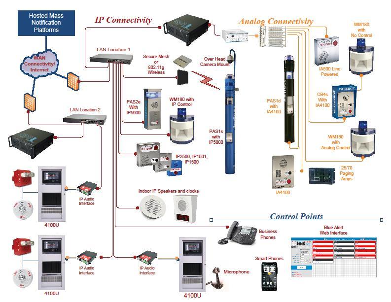
4 Thank you for choosing the Public Address option for your Code Blue application. Public Address is a centralized amplifier-based system designed to provide voice paging and broadcast alarm tones during emergencies. The system can transmit alarm tones and voice messages in a reliable and safe manner from a central location to all or selected areas of the facility via loudspeakers. The entire operational area can be divided into one or more zones, which can be accessed independently either for announcements or alarm broadcasting. Loudspeakers are installed in these zones. There are no limitations to the number of zones in a system or number of loudspeakers in each zone. The system is designed to offer clear reproduction of sound and intelligibility, even in high noise areas. This manual contains all of the Code Blue PAS information needed on the CB 1 series with Public Address, CB 5-s with Public Address, WM-180 Public Address System, CB 2-e with Public Address and 360 PAS retrofit top. This manual contains a general overview of the Code Blue PAS options and its application, installation and wiring. CB 1-s w/ PAS CB 5-s w/ PAS WM 180 CB 2-e w/ Public Address 360 PAS Retrofit Top
5 Large diameter towers; analog or IP An excellent choice when instant mass notification of a geographic area is essential. The unique six-speaker design delivers optimal audio source dispersion utilizing state-of-theart amplifiers and horn array. Small diameter towers Exclusively designed as an emergency communication system to deliver maximum audio clarity and range to ensure notifications are accurately broadcast to your intended audience. Wall or pole mount; analog or IP An excellent choice for parking decks, dorm entrances, hallways and public transit centers where instant mass notification of a geographic area is essential. PAS top kit for existing standard CB 1 series towers in the field to provide public address capabilities. The unique six-speaker design delivers optimal audio source dispersion utilizing state-ofthe-art amplifiers and horn array. Wall or pole mount option remotely adds public address capabilities to new or existing CB units. By adding an analog or IP controller board, you enable the WM-180 to be directly managed by Code Blue s Blue Alert MNS (Mass Notification System) software, granting the user messaging options. The controller also monitors the amplifier and speaker for various failures, which are reported to the appropriate maintenance personnel, and allows the user to call a single WM-180 unit for a targeted message.
6 This regulation covers the application, installation, location, performance, inspection, testing and maintenance of fire alarm systems, supervising station alarm systems, public emergency alarm reporting systems, fire warning equipment and emergency communications systems (ECS), and their components. This provides technical criteria for systems that implement mass notification in compliance with the Department of Defense s antiterrorism requirements. Implement national design standards and recommendations for mass notification systems, as provided in NFPA 72, including Annex E. Code Blue recommends professional services before the order and installation of all PAS products. For survey information, please customerservice@codeblue.com. Ambient Noise Survey: Measures the sound energy flowing into, or outward from, a specified area. System Design Survey Involves the placement, wiring and installation of PAS equipment. Complete Survey Includes ambient noise and system design of PAS equipment. Code Blue Technical Support tss@codeblue.com Toll free: , Opt. 3
7 If the unit emits smoke or an unusual smell, water or other foreign materials enter the enclosure, or the unit is dropped or the enclosure is damaged, power off immediately and contact Code Blue Customer Service. Toll free: , Opt. 2
8 This section covers the following units: CB 1 Series with Public Address, including the 360 PAS Retrofit Kit CB 5-s with Public Address CB 2-e with Public Address WM-180 The following models are covered in the installation instructions for CB 1 Series with Public Address or the 360 PAS Retrofit Kit: CB 1-e CB 1-s CB 1-d Ladder to reach the top of the unit. Security bit to secure the PAS top to the adapter ring. 6mm Allen wrench to secure the PAS adapter ring to the top of the unit. 3/8 socket set - to mount the mounting plate containing the new toroid transformer Remove 120V AC power from the unit Remove the existing dome top assembly. Disconnect the red/black and yellow/yellow wiring harnesses connected to the beacon/strobe mounted in the dome top assembly Place the adapter ring on top of the bollard and tighten the three Allen set screws to hold in place (see Figure 2 on Page 12).
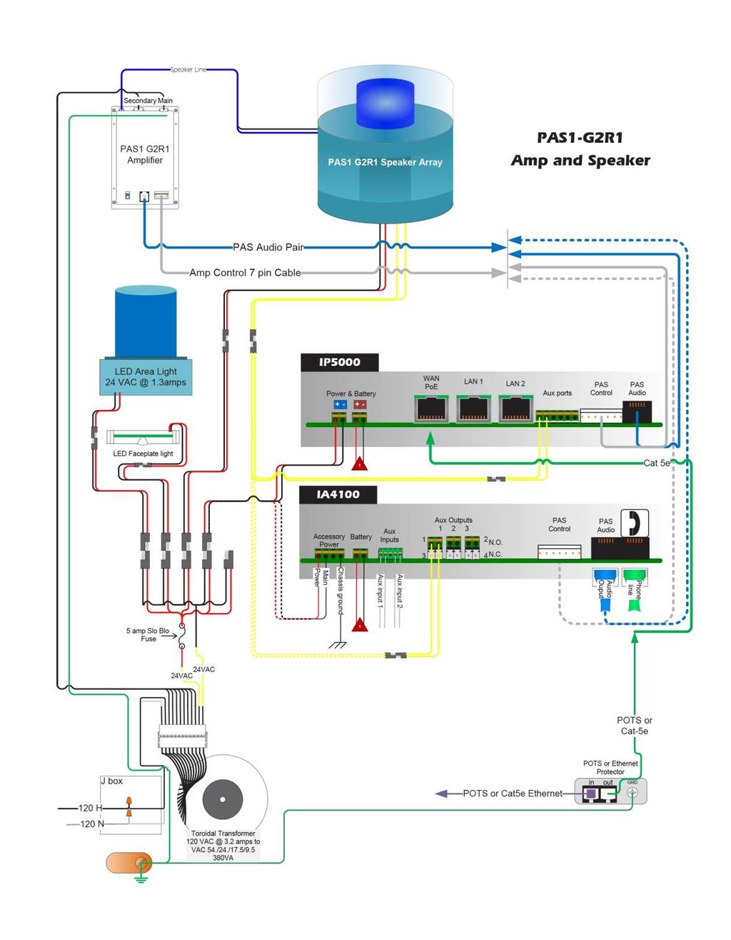
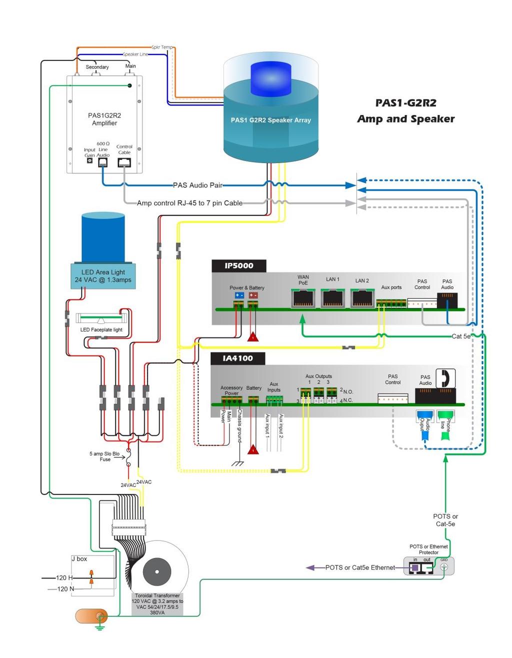
9 Install new toroid transformer. NOTE: Skip this section if you ordered a CB 1 Series with Public Address as a complete unit Remove lower access door on the CB 1 bollard. Remove the existing 120V AC step down transformer Install toroid transformer with mounting plate using supplied hardware (see Figure 1 on Page 10) Connect incoming 120V AC wiring to the transformer using the junction box on mounting plate. Refer to included wiring diagram for wiring terminations (See Figure 5 on Page 19) Run the supplied amplifier wiring harness, beacon/strobe power harness (red/black), beacon/strobe auxiliary harness (yellow/yellow), 7 pin control cable and RJ-11 audio cable to the top of the bollard. Connect the molded quick connector on the red/black harness to the manifold connector on the transformer. Connect the yellow/yellow harness, 7 pin control cable and RJ-11 to the phone board. Connect the large white connector of the amplifier wiring harness to the wiring connector on the transformer. Refer to the included wiring diagram for wiring terminations (See Figure 1 on Page 10).


10 Figure Connect the red/black and yellow/yellow wiring harnesses to the red/black and yellow/yellow wiring pigtails coming from the beacon/strobe Connect the 6 pin wiring harness, 7 pin control cable and RJ-11 audio cable to the ports on the amplifier Set the PAS speaker unit on the adapter ring, lining up the screw holes at the bottom of the unit. Secure the speaker unit with the provided security screws.
11 age 21). Reapply power to the unit (see Error! Reference source not found. on
12 Ladder to reach the top of the unit. Security bit - to secure the PAS top to the adapter ring. 3/8 socket set - to secure the PAS adapter base to the top of the unit. 6mm Allen wrench - to secure the PAS adapter ring to the top of the PAS adapter base Remove 120V AC power from the unit Remove existing beacon/strobe assembly. Disconnect the red/black and yellow/yellow wiring harnesses connected to the beacon/strobe mounted on top of the CB 5-s unit Place a foam gasket on the unit, then the adapter base on top of the bollard and tighten the 3/8 bolts with washers to secure the adapter base to the set screws to hold in place Place adapter ring on top of the adapter base and tighten the three Allen set screws to hold in place (see Figure 2 on Page 12) Connect the red/black and yellow/yellow wiring harnesses to the red/black and yellow/yellow wiring pigtails coming from the beacon/strobe Connect the 6 pin wiring harness, 7 pin control cable and RJ-11 audio cable to the ports on the amplifier Set the PAS speaker unit on the adapter ring, lining up the screw holes at the bottom of the unit. Secure the speaker unit with the provided security screws Reapply power to the unit (See Figure 7 on Page 21).
13 Figure 2
14 Security bit - to remove phone to access mounting holes. ½-inch concrete bit to drill holes in wall for the mounting anchors for mounting bolts. 9/16 socket set - to secure the housing to the wall with mounting bolts Electrical preparation: the unit may have supply wires run from either (a) behind the unit through the wall, or (b) below the unit using an external conduit through the bottom. Holes in the back and bottom have been provided for this purpose (See Figure on Page 23) Remove the top of the unit Mark the mounting holes. In order to comply with the Americans with Disabilities Act (ADA), the speakerphone button(s) should be positioned between 34 and 48 inches from grade level. Consult an ADA specialist in your area to verify local and federal guidelines Drill all marked holes Install the housing. Four anchors of appropriate size and type should be used to fasten the housing to the wall (see Figure 3 on Page 14). IMPORTANT: If wiring is being supplied from the back, ensure that the conduit is aligned at this time Reattach the top Ground The ground (green) wire should be stripped and fastened to the supplied grounding lug V AC supply Using the proper crimping tool, attach a #8 fork to each of the incoming power wires and fasten them to the terminal screws labeled Line and Neutral /240V AC supply Using the proper crimping tool, attach a #8 fork to each of the incoming power wires and fasten them to the correct terminals as


15 labeled on the transformer. After completing the wire connections, install the supplied terminal covers (see Figure on Page 23) Have category 3 or higher 4 pair cable terminated to a RJ45 applying TIA/EIA T568-B specifications. Figure 3
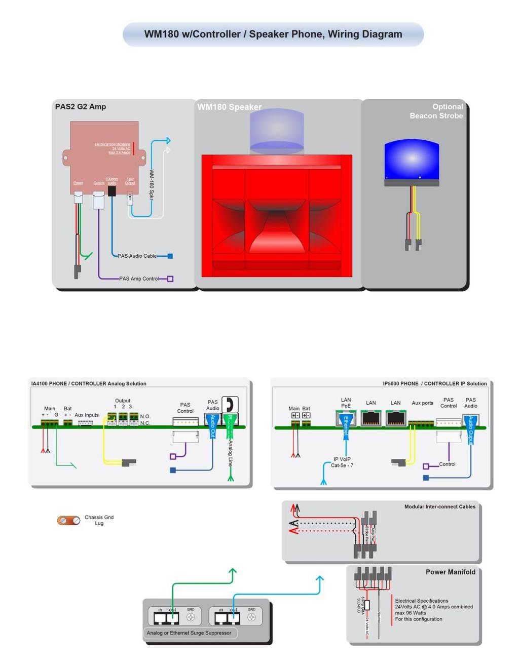
16 Ladder to reach mounting height. Security bit - to remove phone to access mounting holes. ½-inch concrete bit to drill holes for the mounting anchors for the mounting bolts. 9/16 socket set - to secure the housing to the wall with mounting bolt. Note: If unit does not include an IP or Analog controller board, then it must be located near an IA4100 or IP5000 speakerphone for the 20- foot supplied PAS cables to reach it. *See included drawing for anchor bolt and conduit locations Supply 24V AC to Power Manifold (see Figure on Page 22) Supply phone line to phone port if the unit has an analog controller board, or Ethernet IP connection to LAN port if it has an IP controller board Reference IA4100 Admin and User Guide for analog controller board programming Reference IP5000 Admin and User Guide for IP controller board programming Code Blue guides are located at codeblue.com > support > downloads Supply 24V AC to Power Manifold See attached wiring diagram for connecting the PAS Audio Cable and PAS Control Cable to the nearby IA4100 or IP5000 speakerphone Reference IA4100 Admin and User Guide for analog controller board programming.
17 Reference IP5000 Admin and User Guide for IP controller board programming Code Blue guides are located at codeblue.com > support > downloads. Figure 4
18 Designed specifically for schools, hospitals, corporate and municipal campuses looking for an efficient way to detect and respond, Blue Alert MNS (Mass Notification System) fills a need in the marketplace for an incident response solution that is both comprehensive and costeffective. Blue Alert MNS provides emergency notifications over audio, visual and messaging platforms at the touch of a button. The result is a sophisticated software solution that quickly informs and directs people in emergency situations. Blue Alert MNS is available in two editions, Audio/Visual and Messaging, or together in the Blue Alert MNS Professional Package. Blue Alert EMS (Event Management System) handles all incoming emergency and nonemergency events with an easy to use Graphical User Interface (GUI). Effectively utilize EMS for remote operation of Code Blue emergency communication devices. Open gates and AED access doors, turn LED beacon/strobe lights on or off, transfer calls to the Public Address System to make area-wide announcements and incorporate other ancillary devices and applications. Have a camera connected to your Code Blue unit or one mounted nearby? Simply integrate EMS with your CCTV system for instant video when the units are activated. Blue Alert EMS utilizes an advanced API for efficient integration with third party applications. ToolVox UPD (Unit Programming & Diagnostics) software provides a user-friendly, web-based GUI (Graphical User Interface) for the administration of all Code Blue units. Unit Programming, UPD s unique phone management feature, allows the user to easily establish the functionality desired on one phone and copy all settings to additional units as needed. In addition, audio files can be created at a PC and stored on the server. Different messages can then be uploaded to each phone or the same audio file can be used on multiple phones, eliminating the need to call each phone individually and re-record messages. Once settings are complete, simply Click to Program, or select assorted units and choose Program All Units to apply operational parameters. The Diagnostic section of the software package is capable of testing all on-site Code Blue units for functionality at any specified time daily, weekly or on a specified day and time. This flexibility tailors testing at predetermined intervals to confirm the phones are working 24/7.
19 Immediate fault reporting via multiple addresses guarantees minimum response time to any operational issues. Route an to an SMS server and your on-call technician receives a text on their cell phone for immediate deployment, ensuring maximum up time of your units.
20 Figure 5


21 Controller wiring diagram Figure 6

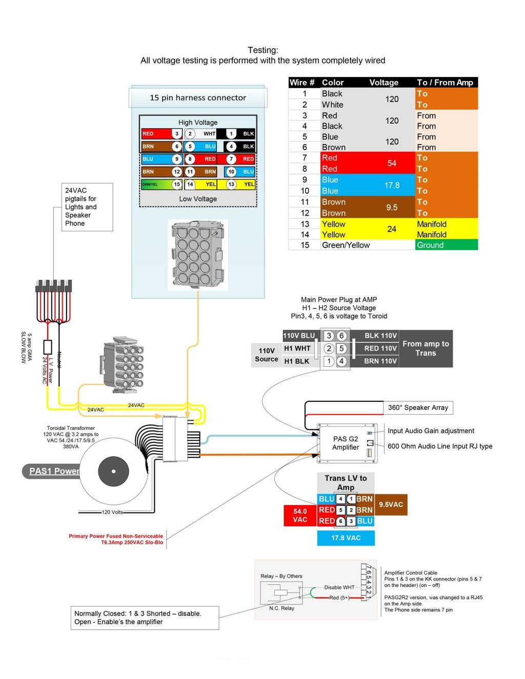
22 Wiring Diagram Figure 7


23 Figure 8
24 Figure 9

25 Figure 10
26 Please contact Code Blue Technical Support if you do not see your issue below Remove the control cable from the amp. This will turn the amp on at all times. Try a new test call Test power from the transformer to the amp manifold. Check the 5 amp slow blow inline fuse between the transformer and 5-finger Check power connector at the 5 finger manifold and the red/black power wire from the strobe Short the yellow relay wires from the strobe to test strobe functionality. If the strobe flashes, check programming in the IA4100/IP5000 speakerphone For CB 1 or 5 units, verify that you have 120V AC to the transformer For CB 2-e units, verify that you have either Hi-Voltage to the power brick or 24V AC to the unit if low voltage only For WM-180 units, verify you have 24V AC to the unit First, adjust the volume in the IA4100/IP5000 programming. On the IA4100, the in-call command for increasing the volume is 28. To decrease the volume, the in-call command is 29. On the IP5000, the Public Address Gain can be changed under hardware settings dial. The input gain also can be adjusted manually on the amplifier using the input gain
27 For advanced trouble shooting, please or call , Opt. 3.
28 Part Number Part Description Notes Amp Assembly Contains amp, toroid transformer and wire harness Dome Top Assembly Contains dome top and active vent Strobe 24V combination blue beacon/strobe Finger Manifold Contains manifold and 5 amp fuse Part Number Part Description Notes Amp Assembly Contains amp and amp harness Strobe 24V combination blue beacon/strobe Finger Manifold Contains manifold and 5 amp fuse Part Number Part Description Notes Amp Assembly Contains amp and amp harness, if needed Finger Manifold Contains manifold and 5 amp fuse
CB 5 Series. Administrator Guide. Installation, Configuration, Operation & Troubleshooting
 CB 5-s CB 5-p CB 5-s with Public Address CB 5-s with Decorative Top Installation, Configuration, Operation & Troubleshooting 800.205.7186 www.codeblue.com WARNING ONLY QUALIFIED PERSONNEL SHOULD INSTALL
CB 4 Series. Administrator Guide. Installation, Configuration, Operation & Troubleshooting. CB 4-s CB 4-r CB 4-u
 CB 4-s CB 4-r CB 4-u Installation, Configuration, Operation & Troubleshooting 800.205.7186 www.codeblue.com WARNING ONLY QUALIFIED PERSONNEL SHOULD INSTALL THESE UNITS. THE INSTALLATION SHOULD CONFORM
CB 1 Series. Administrator Guide. Installation, Configuration, Operation & Troubleshooting
 CB 1-e CB 1-s CB 1 Series with Public Address CB 1-w with Solar/GSM/Wireless Installation, Configuration, Operation & Troubleshooting 800.205.7186 www.codeblue.com WARNING ONLY QUALIFIED PERSONNEL SHOULD
ipulse Installation and User Guide IP2-PoE
 IP2-PoE Hardware Version 2.0 2007 VideogeniX Inc. ipulse PoE Manual P/N: 040-00003-001 Owner s Record The model and serial numbers are located on the bottom of the ipulse unit. Record the serial number
Model HM-535 Power Supply Installation and Service Instructions
 Model HM-535 Power Supply Installation and Service Instructions 430-535 0104 2004 Heritage MedCall, Inc SENTRY INSTALLATION & SERVICE INSTRUCTIONS POWER SUPPLY UNIT Model HM-535 IMPORTANT SAFETY INSTRUCTIONS
ICS Entrance Management Sign Installation Guide. Version 1.0
 ICS Entrance Management Sign Installation Guide Version 1.0 Thank you for purchasing your new ICS Entrance Management System (EMS) from Innovative Control Systems, Inc. Installation Overview This document
HydroGuard 4 to 20 ma Output Module. For use with HydroGuard Water Quality Monitor and Controller
 HydroGuard 4 to 20 ma Output Module For use with HydroGuard Water Quality Monitor and Controller Technician's Manual Installation, Operation, and Maintenance Guide Chapter 1: Preface... 3 1.1 Intended
EP/2 Installation Instructions
 1 2 3 4 7 ENTER 0 5 6 8 9 CLEAR + - LOGIC ONE EP/2 EP/2 Installation Instructions DOC. #569011000 A 7/30/04 PRINTED IN U.S.A. Regulatory Compliance Safety This device has been tested and found to be in
BST Doorphone Installation and Configuration Guide. Avaya Business Communications Manager
 BST Doorphone Installation and Configuration Guide Avaya Business Communications Manager Document Status: Standard Document Number: NN40010-302 Document Version: 02.01 Date: May 2010 2010 Avaya Inc. All
Installation. MGE Galaxy 3500 and Smart-UPS VT. Maintenance Bypass, Distribution and Transformer Cabinet
 Installation MGE Galaxy 3500 and Smart-UPS VT Maintenance Bypass, Distribution and Transformer Cabinet American Power Conversion Legal Disclaimer The information presented in this manual is not warranted
Polycom RealPresence Video Protect 500
 Polycom RealPresence Video Protect 500 SETUP SHEET Video Protect System Group Series 500 Codec Power Supply Handset Ethernet Junction Box AC Junction Box Intelligent Activation Module (IAM) Remote Wall
BST Doorphone Installation and Configuration Guide. BCM Business Communications Manager
 BST Doorphone Installation and Configuration Guide BCM Business Communications Manager Document Status:Standard Document Number: NN40010-302 Document Version: 01.01 Date: June 2006 Copyright 2005 2006
Basketball Shot Clock Set LX2180 Manual
 Basketball Shot Clock Set LX2180 Manual 72 Industrial Boulevard Wrightsville, GA 31096 Phone: (800) 445-7843 Fax: (800) 864-0212 www.electro-mech.com LX2180 Revision 5 February 8, 2013 Table of Contents
IntelliBrite Controller (For IntelliBrite Pool, Spa and Landscape Lighting Fixtures)
") IntelliBrite Controller (For IntelliBrite Pool, Spa and Landscape Lighting Fixtures) Installation and User s Guide IMPORTANT SAFETY INSTRUCTIONS READ AND FOLLOW ALL INSTRUCTIONS SAVE THESE INSTRUCTIONS
IntelliBrite Controller (For IntelliBrite Pool, Spa and Landscape Lighting Fixtures) Installation and User s Guide IMPORTANT SAFETY INSTRUCTIONS READ AND FOLLOW ALL INSTRUCTIONS SAVE THESE INSTRUCTIONS
iconverter 2-Module Power Chassis
 iconverter 2-Module Power Chassis User Manual 38 Tesla, Irvine, CA 92618 USA Phone: (949) 250-6510; Fax: (949) 250-6514 Page 1 Warning The operating description in this Instruction Manual is for use by
60W Power over Ethernet Waterproof Adapter PoE IEEE BT Single Port Injector for Outdoor Application
 WWW.PHIHONG.COM 60W Power over Ethernet Waterproof Adapter PoE IEEE BT Single Port Injector for Outdoor Application Features Compliant with the IEEE802.3bt Standard Non-Vented Case with Mounting Bracket
IntelliBrite Controller (For IntelliBrite Pool, Spa and Landscape Lighting Fixtures) Installation and User s Guide
 Installation and User s Guide") IntelliBrite Controller (For IntelliBrite Pool, Spa and Landscape Lighting Fixtures) Installation and User s Guide *619751* P/N 619751 - Rev B IMPORTANT SAFETY INSTRUCTIONS READ AND FOLLOW ALL INSTRUCTIONS
IntelliBrite Controller (For IntelliBrite Pool, Spa and Landscape Lighting Fixtures) Installation and User s Guide *619751* P/N 619751 - Rev B IMPORTANT SAFETY INSTRUCTIONS READ AND FOLLOW ALL INSTRUCTIONS
BST Doorphone Installation and Configuration Guide. BCM 4.0 Business Communications Manager
 BST Doorphone Installation and Configuration Guide BCM 4.0 Business Communications Manager Document Status: Beta Document Version: 02 Part Code: N0064476 Date: January 2006 Copyright Nortel Networks Limited
BreezeMAX Wi² and BreezeACCESS Wi² Quick Installation Guide
 This Quick Installation Guide is intended for experienced installers. For more information refer to the relevant sections in the BreezeMAX Wi² and BreezeACCESS Wi² System Manual. Wi² Package Content Check
Installing the Camera
 CHAPTER 2 This chapter provides information and instructions for installing the Cisco Video Surveillance PTZ IP camera, and includes the following topics: Installation Guidelines, page 2-1 Warnings Before
1 Installing the VG4-A-ARMPLATE
 VG4 24 VAC Mounting Plate Installing the VG4-A-ARMPLATE en 1 1 Installing the VG4-A-ARMPLATE This addendum provides supplemental information for the AutoDome Modular Camera System Installation Manual.
V-9908 MESSAGE/PAGE PANEL
 Issue 4 V-9908 MESSAGE/PAGE PANEL Introduction These instructions contain the specifications and guidelines necessary to install, operate, and maintain the V-9908, /Page Panel. The V-9908 /Page Panel provides
7" Touch Screen Display
 7" Touch Screen Display Installation Guide Contents Minimum Requirements...1 Select a Location...1 Initial Setup...2 Unboxing...2 Installation...3 Prepare the Panel...3 Install the Mounting Plate...3 Mount
Instruction Manual. Electrical Management System (EMS) EMS-HW30C & EMS-HW50C
 EMS-HW30C & EMS-HW50C") Instruction Manual Electrical Management System (EMS) EMS-HW30C & EMS-HW50C EMS-HW50C EMS-HW30C! CAUTION These instructions are intended to provide assistance with the installation of this product, and
Instruction Manual Electrical Management System (EMS) EMS-HW30C & EMS-HW50C EMS-HW50C EMS-HW30C! CAUTION These instructions are intended to provide assistance with the installation of this product, and
USP-070-B08 USP-104-B10, USP-104-M10 USP-156-B10
 UniStream HMI Panel Installation Guide USP-070-B10, USP-070-B08 USP-104-B10, USP-104-M10 USP-156-B10 Unitronics UniStream platform comprises control devices that provide robust, flexible solutions for
ALTAI C1N SUPER WIFI CPE INSTALLATION GUIDE. Version 1.0 Date: September, Altai Technologies Ltd. All rights reserved
 ALTAI C1N SUPER WIFI CPE INSTALLATION GUIDE Version 1.0 Date: September, 2013 Copyright 2007 Altai Technologies Limited ALL RIGHTS RESERVED. Altai Technologies Limited Unit 209, 2/F, East Wing, Building
GSM-X. Communication module. Quick installation guide. Full manual is available on Firmware version 1.02 gsm-x_sii_en 08/18
 GSM-X Communication module Quick installation guide Full manual is available on www.satel.eu Firmware version 1.02 gsm-x_sii_en 08/18 SATEL sp. z o.o. ul. Budowlanych 66 80-298 Gdańsk Poland tel. +48 58
Encoder Firmware V User s Manual. Outdoor PTZ Camera Hardware Manual KCM /05/09.
 Encoder Firmware V4.06.09 User s Manual Outdoor PTZ Camera Hardware Manual KCM-8211 2013/05/09 1 Table of Contents Precautions... 3 Introduction... 4 List of Models... 4 Package Contents... 5 Safety Instructions...
Now with Picture Memory
 Intrasonic Technology, Inc. Color Video Door Phone / Intercom Installer s Manual Model No.V304KIT-R Now with Picture Memory Please read this manual carefully before the products are installed.technical
*Approved by CSA for non-hazardous locations (Group Safety Publication IEC Third Edition).
.") PowerCore Model MPC-20 Installation Manual *Approved by CSA for non-hazardous locations (Group Safety Publication IEC 61010-1 Third Edition). Products covered in this document comply with European Council
PowerCore Model MPC-20 Installation Manual *Approved by CSA for non-hazardous locations (Group Safety Publication IEC 61010-1 Third Edition). Products covered in this document comply with European Council
Model: CAM430MV Wired Multi-View Camera with License Plate / Rear Surface Mount Installation Manual Features
 Model: CAM430MV Wired Multi-View Camera with License Plate / Rear Surface Mount Installation Manual Features Fully Adjustable, Multiple Viewing Angle Smart Camera. High Resolution, 1/2 CMOS Color Camera
TARA CONTROLS AGC-5. UCI Random Start USER S GUIDE. With Optional Warning Flashes for the Hearing Impaired. TARA CONTROLS by Cartessa Corporation
 TARA CONTROLS AGC-5 UCI Random Start USER S GUIDE With Optional Warning Flashes for the Hearing Impaired TARA CONTROLS by Cartessa Corporation 4825 Cincinnati-Brookville Road Shandon, Ohio 45063 Phone:
Warning Before Installation. Package Contents EN - 1. Refer to your user s manual for the operating temperature.
 5000020G Warning Before Installation English Power off the Network Camera as soon as smoke or unusual odors are detected. Do not place the Network Camera on unsteady surfaces. Do not insert sharp or tiny
Residential/Light Commercial Remote Control System
 MODULAR CONTROLLER REMOTE CONTROL Residential/Light Commercial Remote Control System OWNER S MANUAL AND INSTALLATION INSTRUCTIONS CONTENTS INTRODUCTION 2 SYSTEM COMPONENTS - REMOTE 3 SYSTEM COMPONENTS
Shop Fox Fence Kit Installation Instructions:
 Shop Fox Fence Kit Installation Instructions: Please note this installation kit is designed solely for installation on a Shop Fox Classic Fence. Accurate Technology manufactures kits for other saw fences
NCH-1000 (Multiple Breaker Types) Installation Instructions
 Installation Instructions") 20M1 12345678 NCH-1000 (Multiple Breaker Types) Installation Instructions DOC. #560502100 C 7/30/04 PRINTED IN U.S.A. Regulatory Compliance Safety This device has been tested and found to be in compliance
20M1 12345678 NCH-1000 (Multiple Breaker Types) Installation Instructions DOC. #560502100 C 7/30/04 PRINTED IN U.S.A. Regulatory Compliance Safety This device has been tested and found to be in compliance
2-Way Wireless I/O Expander Installation Guide
 2-Way Wireless I/O Expander Installation Guide For more detailed information please refer to the iconnect Installer Manual provided on our website: www.electronics-line.com Table of Contents 1. Introduction...
SuperBus 2000 Phone Interface/Voice Module Installation Instructions
 SuperBus 2000 Module Installation Instructions Product summary The SuperBus 2000 (PIV) Module provides phone and voice functions for the Concord, Concord 4, and Concord Express (v4) panels. The PIV module
Installation Notes TII Model 341 Protector
 Installation Notes TII Model 341 Protector (ATT-IS PEC 32918) for MERLIN Communications System In Range Out of Building (IROB) Station Installation By Trained Technician Only WARNING: Failure to follow
PICO PROTECTOR PG-25 & PK-25 Series
 PICO PROTECTOR PG-25 & PK-25 Series Installation Instructions LISTED 95P5 SIGNAL CIRCUIT PROTECTOR Introduction The Siemon Company s Pico Protector Kits protect voice and data equipment from sneak current
The power behind competitiveness. Delta Infrasuite Power Management. Power Distribution Unit. User Manual.
 The power behind competitiveness Delta Infrasuite Power Management Power Distribution Unit User Manual www.deltapowersolutions.com Save This Manual This manual contains important instructions and warnings
Carefree-Security. Installation and programming instructions 1050A. Owner s Manual
 Carefree-Security Heavy Duty Commercial - Industrial Fully Sealed Digital Access Keypad Specially Designed for Gate Operators, Overhead Doors, Specialty Doors & Electric Door Locking Devices SINGLE OR
Telephone Entry System
 Telephone Entry System TE-200-II C-0902 (PCB w/ mounting plate) 234 FISCHER AVENUE COSTA MESA, CA 92626 (714) 424-6500 (800) 840-0288 (714) 424-6510 FAX HTTP://WWW.CHANNELVISION.COM E-MAIL: SALES@CHANNELVISION.COM
HVG400. Installation Guide
 HVG400 Installation Guide September 2013 Trademarks & Copyright Trademarks All trademarks mentioned in this manual are the sole property of their respective manufacturers. Copyright Ltd., Jerusalem, Israel
SERVICE MANUAL FOR MODEL WPP-531-X-ADA-STROBE WEATHERPROOF TELEPHONE WITH OPTIONAL STROBE FEATURE. EQUIPPED WITH SPK1.
 WPP-531-X-ADA-STROBE(LP3P)-SPK1.07UNVLr3-ISSUE4.0 SERVICE MANUAL FOR MODEL WPP-531-X-ADA-STROBE WEATHERPROOF TELEPHONE WITH OPTIONAL STROBE FEATURE EQUIPPED WITH SPK1.07UNVLr3 FIRMWARE Serving the Telephone
TECHKNOW, INC. Kiosk Order Confirmation System INSTALLATION MANUAL. Revision Date: July 11, 2012 Part # Version 3.2
 document Page 1 of 18 TECHKNOW, INC Kiosk Order Confirmation System INSTALLATION MANUAL Revision Date: July 11, 2012 Part # Version 3.2 Techknow, Inc. 393 Mayfield Road Duncan, SC 29334 www.gotechknow.com
Install Motor Controller User Manual
 Property of Motion Laboratories, Inc. Install Motor Controller User Manual 2014 Motion Laboratories, Inc. Created By: Michael Shaw Approved By: John Coppolecchia Page: 1 Page: 2 2014 Motion Laboratories,
MICHIGAN DEPARTMENT OF TRANSPORTATION
 MICHIGAN DEPARTMENT OF TRANSPORTATION SPECIAL PROVISION FOR GROUNDING, BONDING, LIGHTNING PROTECTION AND SURGE PROTECTION FOR INTELLIGENT TRANSPORTATION SYSTEM EQUIPMENT ITS:CLC 1 of 5 APPR:LWB:DBP:07-31-13
Roughneck V920D Series Camera Domes XX Quick Guide
 Quick Guide XX258-20-06 Roughneck V920D Series Camera Domes Vicon Industries Inc. Tel: 631-952-2288 Fax: 631-951-2288 Toll Free: 800-645-9116 24-Hour Technical Support: 800-34-VICON (800-348-4266) UK:
CONSOLE CONNECTOR KIT 9501 INSTALLATION INSTRUCTIONS
 CONSOLE CONNECTOR KIT 9501 INSTALLATION INSTRUCTIONS FOR USE WITH: HAMMOND Organ Models L-100, M-100 Series, M-l, M-2, M-3 LESLIE Speaker Models 760, 770, 825 KIT CONTENT Console Connector Assembly 043075
FEATURES. AlphaBlueLight Emergency Towers Installation & Operations Manual FIGURE 1: FRONT & REAR VIEWS
 AlphaBlueLight Emergency Towers Installation & Operations Manual FIGURE 1: FRONT & REAR VIEWS FEATURES ADA Compliant (hands free operation) LED call status indicator Powder coated steel construction inside
X-618 Public Address and Voice
 X-618 Public Address and Voice Alarm System Installation Manual M_XXXXXX_EN_1.0 Copyright 2012 Honeywell International Inc. All rights reserved. No part of this document may be reproduced in any form
Outdoor PTZ. Mounting on the Ceiling Using Pendant Mount. Installation Guide. For Models: I93, I94, I95, I96, KCM /12/03
 Outdoor PTZ Mounting on the Ceiling Using Pendant Mount For Models: I93, I94, I95, I96, KCM-8211 2013/12/03 Table of Contents Mounting Solutions... 3 Straight Tube Installation Procedures... 4 Step 1:
InnoMedia Business VoIP ATA Models
 InnoMedia Business VoIP ATA Models MTA8328-4, MTA8328-8, MTA8328-24 Quick Installation Guide Important Safety Instructions Protective Earthing Protective earthing is used as a safeguard. This equipment
Agilent 70612B K18 Switch Matrix
 Agilent 70612B K18 Switch Matrix Hardware Reference Manual Agilent Technologies COPYRIGHT 2000 AGILENT TECHNOLOGIES, INC. ALL RIGHTS RESERVED. NO PART OF THIS DOCUMENT MAY BE REPRODUCED IN ANY FORM OR
COOPER POWER SERIES. RS-485 digital communications accessory board installation and operation instructions. Voltage Regulators MN225074EN
 Voltage Regulators MN225074EN Effective March 2017 Supersedes January 2012 (S225-40-7) RS-485 digital communications accessory board installation and operation instructions COOPER POWER SERIES DISCLAIMER
KTD-125/ KTD-125P/125P-24 KTD-127/127W PTZ Receivers
 KTD-125/125-24 KTD-125P/125P-24 KTD-127/127W PTZ Receivers 2003 Kalatel, a GE Interlogix company All Rights Reserved. Any GE Interlogix, Kalatel division, software supplied with GE Interlogix, Kalatel
User s Manual. ACS550-PD 3R Irrigation Packaged Drive Supplement to ACS550-U1 User s Manual
 User s Manual ACS550-PD 3R Irrigation Packaged Drive Supplement to ACS550-U1 User s Manual 2 ACS550-PD 3R Irrigation Packaged Drive ACS550 Drive Manuals GENERAL MANUALS ACS550-U1 User s Manual (1 200 HP)
Instruction Manual. M Pump Motor Controller. For file reference, please record the following data:
 Instruction Manual M Pump Motor Controller For file reference, please record the following data: Model No: Serial No: Installation Date: Installation Location: When ordering replacement parts for your
Progressive Industries, Inc. EMS Electrical Management System
 Progressive Industries, Inc. EMS Electrical Management System Complete Installation Guide and Operating Instructions for: Model EMS-LCHW50 Rated at 240V/50A Manufactured by: Progressive Industries, Inc.
(1986; Rev. 1989) Molded Case Circuit Breakers and Molded Case Switches. (1985; Rev. 1988) Enclosures for Electrical Equipment (1000 Volts Maximum)
 Molded Case Circuit Breakers and Molded Case Switches. (1985; Rev. 1988) Enclosures for Electrical Equipment (1000 Volts Maximum)") Section 16306 50/60-HERTZ (HZ) SOLID STATE FREQUENCY CONVERTER Index PART 1 GENERAL PART 2 PRODUCTS 1.1 References 2.1 Frequency Converters 1.2 Factory Tests 2.2 Conduit and Fittings 1.3 Submittals 2.3
Section 16306 50/60-HERTZ (HZ) SOLID STATE FREQUENCY CONVERTER Index PART 1 GENERAL PART 2 PRODUCTS 1.1 References 2.1 Frequency Converters 1.2 Factory Tests 2.2 Conduit and Fittings 1.3 Submittals 2.3
ShoreTel IP Phone 655. Quick Install Guide & Warranty
 ShoreTel IP Phone 655 Quick Install Guide & Warranty Document and Software Copyrights Copyright 1998-2012 by ShoreTel Inc., Sunnyvale, California, USA. All rights reserved. Printed in the United States
PV Rapid Shutdown device
 PV Rapid Shutdown device Installation and Operation Manual Solis-RSD-1G(1:1) Solis-RSD-1G(2:2) Manufacturer: Ginlong (Ningbo) Technologies Co.,Ltd., Ningbo, Zhejiang, P.R.China US Office: 565 Metro Pl.
Sarix Professional IMP Series 3.75 Indoor Dome. Quick Start Guide IMP121-1IS IMP221-1IS IMP321-1IS IMP521-1IS C2291M-B-EN (12/16)
") Sarix Professional IMP Series 3.75 Indoor Dome Quick Start Guide IMP121-1IS IMP221-1IS IMP321-1IS IMP521-1IS C2291M-B-EN (12/16) Sarix Professional IJP Series 2 Micro Indoor Dome Quick Start Guide IJP121-1IS
Sarix Professional IMP Series 3.75 Indoor Dome Quick Start Guide IMP121-1IS IMP221-1IS IMP321-1IS IMP521-1IS C2291M-B-EN (12/16) Sarix Professional IJP Series 2 Micro Indoor Dome Quick Start Guide IJP121-1IS
SERVICE MANUAL MODEL WPP-531-X-ADA MODEL SSP-511- X-ADA
 WPP-531-X-ADA OR SSP-511-X-ADA-SPK1.07-ISSUE4.0 SERVICE MANUAL FOR MODEL WPP-531-X-ADA HANDS FREE EMERGENCY WEATHERPROOF TELEPHONE OR MODEL SSP-511- X-ADA HANDS FREE STAINLESS STEEL PANEL TELEPHONE EQUIPPED
Electrical Management System (EMS) EMS-HW30C & EMS-HW50C
 EMS-HW30C & EMS-HW50C") Electrical Management System (EMS) EMS-HW30C & EMS-HW50C Installation & Operating Guide for: Model EMS-HW30C Rated at 120V/30A and Model EMS-HW50C Rated at 240V/50A Surgio Says Lifetime Warranty on all
Electrical Management System (EMS) EMS-HW30C & EMS-HW50C Installation & Operating Guide for: Model EMS-HW30C Rated at 120V/30A and Model EMS-HW50C Rated at 240V/50A Surgio Says Lifetime Warranty on all
When any of the following symbols appear, read the associated information carefully. Symbol Meaning Description
 Uni-I/O Modules Installation Guide UID-0808R, UID-0808T, UID-1600,UID-0016R, UID-0016T Uni-I/O is a family of Input/Output modules that are compatible with the UniStream control platform. This guide provides
QUICK START GUIDE. 1. How to register your Camera to Hubble account A. Setting Up the Camera - can be connected via WiFi or LAN
 MODEL: FOCUS72 FOCUS72-2 FOCUS72-3 FOCUS72-4 FOCUS72-W FOCUS72-W2 FOCUS72-W3 FOCUS72-W4 QUICK START GUIDE For a full explanation of all features and instructions, please refer to the User s Guide. (available
Installing and Cabling Flexi Zone Micro High Power 2x20 W BTS DN Issue 02 Approval Date yyyy-mm-dd
 Nokia Networks Installing and Cabling Flexi Zone Micro High Power 2x20 W BTS DN09229011 Issue 02 Approval Date yyyy-mm-dd Installing and Cabling Flexi Zone Micro High Power The information in this document
Installation and User Guide
 Installation and User Guide VADDIO DOMEVIEW HD INDOOR PENDANT MOUNT DOME ENCLOSURE FOR THE VADDIO HD-20, HD-19 AND HD-18 PTZ CAMERAS Part Number: 998-9100-200 2011 Vaddio - All Rights Reserved DomeVIEW
Operating instructions. Switching amplifier DN0210 DN / / 2015
 Operating instructions Switching amplifier DN0210 DN0220 UK 80011079 / 00 01 / 2015 Contents 1 Preliminary note...4 1.1 Symbols used...4 1.2 Warning signs used...4 2 Safety instructions...5 2.1 General...5
Biesemeyer Fence Kit Installation Instructions:
 Biesemeyer Fence Kit Installation Instructions: Please note this installation kit is designed solely for installation on a Biesemeyer Commercial Fence. Accurate Technology manufactures kits for other saw
FortiCam FD40 Mounting Guide
 FortiCam FD40 Mounting Guide 1 FORTINET DOCUMENT LIBRARY http://docs.fortinet.com FORTINET VIDEO GUIDE http://video.fortinet.com FORTINET BLOG https://blog.fortinet.com CUSTOMER SERVICE & SUPPORT https://support.fortinet.com
DP-222Q Color Video Door Phone Manual
 DP-222Q Color Video Door Phone Manual * has 6 LEDs for nighttime operation Remotely and securely talk to visitors and unlock doors, gates, etc. from the Easily connect a secondary * Simple 2-wire connection
FortiCam SD20 Mounting Guide
 FortiCam SD20 Mounting Guide FortiCam SD20 Mounting Guide April 14, 2016 Copyright 2016 Fortinet, Inc. All rights reserved. Fortinet, FortiGate, FortiCare and FortiGuard, and certain other marks are registered
Z-Wave Certified Wireless Lighting Control. Auxiliary Switch ZW2001 ZW2002 rev. 09/01/11
 Z-Wave Certified Wireless Lighting Control Auxiliary Switch 45610 ZW2001 ZW2002 rev. 09/01/11 This auxiliary switch is a component of the JASCO Z-Wave lighting control system and is designed to work with
KRONOS INSTALLATION INSTRUCTIONS
 INSTALLATION INSTRUCTIONS TABLE OF CONTENTS ENCLOSURE AND DONGLE ASSEMBLY 1 LIGHTED ENCLOSURES 2-10 2 SLIM ENCLOSURE 11-17 3 WIRED-ETHERNET DONGLE 18-25 4 REAR-OFFSET MOUNT 26-33 5 SIDE-MOUNT 34-41 6 SURFACE
INSTALLATION INSTRUCTIONS
 INSTALLATION INSTRUCTIONS 3YEAR WARRANTY & LIMITATION OF LIABILITY TRI-TRONICS COMPANY, INC. warrants that the products delivered by it will be of the kind and quality described in the order or contract
Navigator II INstallatIoN MaNUal For static and PaN/tIlt configurations
 Navigator II Installation MANUAL For Static and Pan/Tilt Configurations Document Number: 432-0001-00-12, rev 100 FLIR Systems, Inc., 2008. All rights reserved worldwide. No parts of this manual, in whole
When any of the following symbols appear, read the associated information carefully. Symbol Meaning Description
 Uni-I/O Wide Modules Installation Guide UID-W1616R, UID-W1616T Uni-I/O Wide is a family of Input/Output modules that are compatible with the UniStream control platform. Wide Modules are 1.5 times as wide
RMB Peripheral Units Installation Guide
 RMB Peripheral Units Installation Guide Part Number 65-000101 2011 by Kentrox, Inc. All rights reserved. Copyright 2011 by Kentrox, Inc. All Rights Reserved. The material discussed in this publication
Bluetooth Enabled Access Control MODEL BG-FE. Operating Instructions
 BlueGuard FE Bluetooth Enabled Access Control MODEL BG-FE Operating Instructions CAUTION AND SAFETY INFORMATION IMPORTANT: If the equipment is used in a manner not specified in this manual, the protection
When any of the following symbols appear, read the associated information carefully. Symbol Meaning Description
 Uni-I/O Modules Installation Guide UIA-0402N Uni-I/O is a family of Input/Output modules that are compatible with the UniStream control platform. This guide provides basic installation information for
FE8171V. 3MP 360 Panoramic View Vandal-proof
 FE8171V 3MP 360 Panoramic View Vandal-proof Warning Before Installation English Power off the Network Camera as soon as smoke or unusual odors are detected. Refer to your user's manual for the operating
1. Mount the echo and tremolo control switches under the keyboard shelf, in a position convenient for the organist.
 CONSOLE CONNECTOR KIT 8101 INSTALLATION INSTRUCTIONS FOR USE WITH: HAMMOND Organ Models A-100, D-100, RT2, RT3 LESLIE Speaker Models 122, 122RV KIT CONTENT Console Connector Assembly 047357 Echo Control
I/O Expansion Box Installation & Operator s Instruction Manual
 I/O Expansion Box Installation & Operator s Instruction Manual May 2004 CTB Inc. Warranty I/O Expansion Box CTB Inc. Warranty CTB Inc. warrants each new Chore-Tronics product manufactured by it to be free
Installation Guide V290 (Color) This guide provides basic information for Unitronics LCD color touchscreen models V C30B and V T40B.
 This guide provides basic information for Unitronics LCD color touchscreen models V C30B and V T40B.") Vision OPLC Installation Guide V290 (Color) This guide provides basic information for Unitronics LCD color touchscreen models V290-19-C30B and V290-19-T40B. General Description Vision OPLCs are programmable
Vision OPLC Installation Guide V290 (Color) This guide provides basic information for Unitronics LCD color touchscreen models V290-19-C30B and V290-19-T40B. General Description Vision OPLCs are programmable
Outdoor Hemispheric Mounting on the Ceiling with Gang Box (Face Down)
") Outdoor Hemispheric Mounting on the Ceiling with Gang Box (Face Down) Installation Guide For Models: KCM-7911 2014/01/17 Table of Contents Installation Procedures... 3 Step 1: Prepare for Waterproof Installation...
Outdoor Hemispheric Mounting on the Ceiling with Gang Box (Face Down) Installation Guide For Models: KCM-7911 2014/01/17 Table of Contents Installation Procedures... 3 Step 1: Prepare for Waterproof Installation...
Omnitron Systems Technology, Inc. 1. iconverter. 19-Module Managed Power Chassis User s Manual
 Omnitron Systems Technology, Inc. 1 iconverter 19-Module Managed Power Chassis User s Manual 27 Mauchly, #201, Irvine, CA 92618 Phone: (949) 250-6510; Fax: (949) 250-6514 2 Omnitron Systems Technology,
Outdoor Alerting System
 Outdoor Alerting System System Installation, Operation and Maintenance Manual EN.PM.UM18 20151104 Copyright Copyright 2011, by Earth Networks, Inc. All Rights Reserved. Manual Copyright, 2011, by Earth
SM Sygnus Hybrid Quick Installation Guide Version
 SM Sygnus Hybrid Quick Installation Guide Version 1.0.4 2017 WARNINGS Do not work on the system or connect or disconnect cables during periods of lightning activity. This equipment must be grounded. Never
Ethernet Adapter Installation Instructions
 Ethernet Adapter Installation Instructions DOC. #569040000 A 7/30/04 PRINTED IN U.S.A. Disclaimer Logic One is a registered trademark of Novar Controls Corporation. The material in this manual is for information
Outdoor Alerting System
 Outdoor Alerting System System Installation, Operation and Maintenance Manual July 2011 Release 1, Version 1.0 Copyright Copyright 2011, by Earth Networks, Inc. All Rights Reserved. Manual Copyright, 2011,
PTT-100-VZ Wireless Speaker Microphone
 Federal Communication Commission Interference Statement This equipment has been tested and found to comply with the limits for a Class B digital device, pursuant to Part 15 of the FCC Rules. These limits
Operating instructions. Speed monitor D / / 2014
 Operating instructions Speed monitor D200 80005257 / 00 05 / 2014 Contents 1 Preliminary note...4 1.1 Symbols used...4 1.2 Warning signs used...4 2 Safety instructions...5 2.1 General...5 2.2 Target group...5
Explosion-Protected Arc-Fault Protection ExAFCI Arc-Fault Circuit Interrupter
 Installation, Operation & Maintenance Sheet Explosion-Protected Arc-Fault Protection ExAFCI Arc-Fault Circuit Interrupter > Contents 1 Contents 1 Contents...2 2 General Information...2 2.1 Manufacturer...2
Quuppa LD-7L Installation Guide and Safety Information
 Quuppa LD-7L Installation Guide and Safety Information 1 Quuppa LD-7L Installation Guide and Safety Information 2016 Quuppa Contents For your safety Introduction Quuppa LD-7L dimensions Safety Information
DP2 DOOR PHONE. For Technical Assistance Please Phone: (07)
") DP2 DOOR PHONE For Technical Assistance Please Phone: (07) 5596 5128 TABLE OF CONTENTS Description Page 3 Door Phone Dimensions Page 4 Door Phone Range Page 5 Door Phone Performance Page 6 Operation Summary
DP2 DOOR PHONE For Technical Assistance Please Phone: (07) 5596 5128 TABLE OF CONTENTS Description Page 3 Door Phone Dimensions Page 4 Door Phone Range Page 5 Door Phone Performance Page 6 Operation Summary
This guide provides basic information for Unitronics Models 230/260/280/290 (Non-color Screens).
.") Vision OPLC Installation Guide Models 230/260/280/290 (Non-color Screens) This guide provides basic information for Unitronics Models 230/260/280/290 (Non-color Screens). General Description Vision OPLCs
Vision OPLC Installation Guide Models 230/260/280/290 (Non-color Screens) This guide provides basic information for Unitronics Models 230/260/280/290 (Non-color Screens). General Description Vision OPLCs
EntraGuard Bronze. Quick Start Guide. Telephone Entry. 1.0 Specifications. 2.0 Unit Installation
 The EntraGuard Bronze is a residential telephone keypad entry system which allows a homeowner to communicate directly with visitors and provide access by using any phone extension in the home. Because