1 Contents. Selection guide RXC, RXB, RXL, RXA. System overview DESIGO RXB. Hardware overview DESIGO RX
|
|
|
- Paulina Heath
- 5 years ago
- Views:
Transcription
1 DESIGO RXB (KNX) Technical manual Version 2.37 and higher 2 1 Contents Selection guide RXC, RXB, RXL, RXA 3 System overview DESIGO RXB Hardware overview DESIGO RX Data sheets RXB (KNX) Room controllers, Room unit CLC & RAD Chilled ceiling and radiator applications FNC Fancoil applications 8 RXB, RXL Installation guide 9 CM110389en_06 30 Jun
2
3 CM110389en_06 DESIGO RXB (KNX) Technical manual Version 2.37 and higher s CM110389en_06 DESIGO RXB (KNX) Technical manual Version 2.37 and higher s CM110389en_06 DESIGO RXB (KNX) Technical manual Version 2.37 and higher s CM110389en_06 DESIGO RXB (KNX) Technical manual Version 2.37 and higher s CM110389en_06 DESIGO RXB (KNX) Technical manual Version 2.37 and higher s CM110389en_06 DESIGO RXB (KNX) Technical manual Version 2.37 and higher s CM110389en_06 DESIGO RXB (KNX) Technical manual Version 2.37 and higher s CM110389en_06 DESIGO RXB (KNX) Technical manual Version 2.37 and higher s
4
5 Contents RXB (KNX) Tab 01 Contents CM Tab 02 Selection guide DESIGO RXC, RXB, RXL, RXA CA Tab 03 DESIGO RXB System overview CM Tab 04 DESIGO RX Hardware overview CA2N3804 Tab 05 DESIGO RXB (KNX) Data sheets RXB21.1, RXB22.1 Room controllers for fan-coil systems (FC-10, FC-11, FC-12) CM2N3873 RXB24.1 Room controllers chilled ceiling and radiator systems (CC-02) CM2N3874 QAX34.3 Room unit with PPS2-interface. With temperature sensor, setpoint adjustment, /Auto / Fan speed switch, with LCD display for room temperature and operating mode, with HandyTool function CM2N1640 (For more room units, refer to the DESIGO RX hardware overview in Tab 04) Tab 06 CLC & RAD Chilled ceiling and radiator applications Description of functions for CC-02 Applications from CC-02 CM CM Tab 07 FNC Fancoil applications Description of functions for FC-10, FC-11, FC-12 Applications from FC-10, FC-11, FC-12 CM CM Tab 08 DESIGO RXB / RXL Installation guide CM Siemens Technical manual DESIGO RXB (KNX) CM110389de01_05 Building Technologies Contents
6


7 Building Automation DESIGO RXC, RXB, RXL, RXA Room automation systems Selection guide RXC RXB RXL RXA Proprietary Communications Non-communicating Flexibility 10331Z01en Functionality LONWORKS bus
8 Solutions meeting a variety of needs The DESIGO RX room automation systems take care of comfort in individual rooms or self-contained zones. In this process, the temperature and quality of the indoor air can be adjusted by use of an operator unit (the "room unit"). The system is rounded off by integrated room units for the operation of HVAC, lighting and blinds where required. In addition to the room controllers, extension modules and room units, technically sophisticated application libraries are available, covering the large majority of common HVAC and electrical applications. Integration into the DESIGO building automation & control system DESIGO Communication LONWORKS bus Proprietary communication Room controllers and accessories from Siemens or third-party manufacturers RXC LONWORKS standard devices RXB KNX / EIB standard devices RXL RXA Identical range of functions in the applications Identical room units RAD, CLC, FNC, VAV, FPB QAX Z02en_01 Principal features The four ranges, RXC, RXB, RXL, and RXA are tailored to the various bus systems used in buildings: RXC: LON bus communication RXB: KNX / EIB bus communication RXL: Proprietary communication RXA: Stand-alone (non-communicating) RXC: RXB: RXL: RXA: RXC offers the widest selection of HVAC applications, and integrated applications incorporating lighting and blinds. The RXC controllers are therefore suitable for more sophisticated HVAC applications where control of lighting and blinds form part of the requirements. An important benefit is the scope for combined operation of HVAC, lighting and blinds in a single room unit. RXB offers HVAC room control based on KNX / EIB technology. In addition to the HVAC functions, sophisticated electrical functions can also be implemented in conjunction with commercially available KNX / EIB equipment. RXB is thus primarily suitable for systems where, in addition to the HVAC controls, there is an emphasis on electrical functions. RXL offers HVAC room control based on proprietary communication. RXL is primarily suitable for systems where the emphasis is on a costeffective HVAC solution for DESIGO without additional functions. RXA is the ideal solution for fan-coil systems where no communications are required. 2 / 4
 RAD, CLC,FNC (selected via tool) FNC (selected via DIP switch) Room units for HVAC operation Electrical controls (lighting, blinds) Conventional switches EIB")
 - - - - Integration into the DESIGO - - building automation and control system Commissioning tool DESIGO RXT10 ETS3")
 ACS, HandyTool DIP switches Other documentation: System description CA110333 CA2S3879 (EIB) CM110780 CA2S3880 CM110380 (KNX) Applications library CA110300 CA2A3899 (EIB) CM110389 (KNX) CM110789")

 Selection of fan speed LCD display for room temperature, operating mode and fan speed Exchangeable pushbuttons for control of lighting and blinds Downloadable")
9 Product scope RXC RXB RXL RXA Communication LON KNX / EIB Proprietary - - Applications (HVAC functions) and suitable controllers (see page 4 for details) RAD, CLC, FNC, VAV, FPB, INT (downloadable) RAD, CLC,FNC (selected via tool) RAD, CLC,FNC (selected via tool) FNC (selected via DIP switch) Room units for HVAC operation Electrical controls (lighting, blinds) Conventional switches EIB third-party devices - - Convention al switches Operation of HVAC, lighting and blinds over bus QAX5... EIB third-party devices Integration of third-party devices (field level) Integration into the DESIGO - - building automation and control system Commissioning tool DESIGO RXT10 ETS3 Professional, (ACS, HandyTool from V2.36) ACS, HandyTool DIP switches Other documentation: System description CA CA2S3879 (EIB) CM CA2S3880 CM (KNX) Applications library CA CA2A3899 (EIB) CM (KNX) CM CA2Z3889 Room units DESIGO RX includes a range of stylish room units designed to satisfy a wide variety of demands, from simple temperature sensing to integrated operation of HVAC, lighting and blinds at room level. Room unit functions QAX 30.1, 31.1 QAX 32.1 QAX 33.1 QAX 34.1 QAX 34.3 QAX 84.1/ PPS2 QAX 39.1 QAX 90.1, 91.1 QAX 95.1, 96.1 QAX 50.1, 51.1 Built-in room temperature sensor Room temperature setpoint adjustment QAX 31.1 QAX 91.1 QAX 96.1 Selection of operating mode ( /Auto) Selection of fan speed LCD display for room temperature, operating mode and fan speed Exchangeable pushbuttons for control of lighting and blinds Downloadable application software for operation of lighting and blinds PPS2 interface to room controller LONWORKS bus communication 2) KNX bus communication 2) Wireless room units 1) Batteryless EnOcean technology 2) HandyTool (Parametrization of KNX RXB controllers) Suitable for... RXC RXA, RXB, RXL, PX 3) 1) The RXZ90.1 receiver is the PPS2 interface for the QAX90.1 / 91.1 room units 2) The RXZ95.1 gateway is the LONWORKS interface, The RXZ97.1 gateway is the KNX interface to the QAX95.1 / 96.1 room units 3) All room units apart from the QAX5 can also be used at the automation level (DESIGO PX). However, the displays on room units QAX32.1, QAX33.1, QAX34.1, QAX34.3or QAX84.1 only show the request of the user and not the effective state 3 / 4
10 Applications The comprehensive application library contains predefined standard applications for radiators, chilled ceilings, fan-coil units, VAV and fan-assisted VAV units, and integrated applications for HVAC, lighting and blinds. The library is continuously updated. Use Application (software) RXC... RXB... RXL... RXC Radiator / chilled ceilings RAD01 LTHW radiator RAD03 Electric radiator CLC01 Chilled ceiling CLC02 Chilled ceiling and radiator-type heating CLC03 Chilled ceiling and electric radiator CLC06 Chilled/heated ceiling, two-pipe system with change-over via LON bus CLC07 Chilled/heated ceiling, two-pipe system with change-over via LON bus and radiator etc. Fan-coil units FNC02 Two-pipe system with change-over FNC03 Two-pipe system with change-over and electric re-heater FNC04 Four-pipe FNC05 Four-pipe system with electric reheater FNC08 Four-pipe system with room supply air cascade control FNC10 Two-pipe system with change-over and outside air damper FNC20 Four-pipe system with controlled air damper etc. Variable air volume systems VAV01 Single-duct supply or extract air system VAV02 Single duct supply air system with reheater or cooling coil VAV03 Single-duct supply air system with electric re-heater VAV04 Single-duct supply and extract air system VAV05 Single-duct supply/extract air system with re-heater / cooler VAV06 Single duct supply and extract air system with electric re-heater etc. Fan-powered box FPB05 Fan Powered Box unit with electric reheater (Fan-assisted VAV) Integrated applications (HVAC, lighting and blinds) HVAC Lighting Blinds INT02 CLC02 4 on/off INT03 CLC02 2 on/off + 2 dimming INT05 CLC02 2 on/off 4 up/down INT07 CLC02 2 on/off + 2 dimming 2 up/down etc. INT11 VAV08 4 on/off INT12 VAV08 2 dimming INT15 VAV08 2 on/off 2 up/down KNX / EIB third-party devices (Conventional switches) etc. Siemens Switzerland Ltd Building Technologies Division International Headquarters Gubelstrasse 22 CH-6301 Zug Tel Fax / Siemens Switzerland Ltd CA110331en_03 Subject to change 31 Jan 2009


11 Building Automation RXB room automation system System overview
12
13 Contents Comfort and well-being in every room...5 Range overview...6 Coordinated room controllers...7 The room units: the key to individual comfort...8 Applications...10 Installation...11 Engineering and commissioning...12 Integration into building automation and control systems...15 RXB overview
14 4

15 Comfort and well-being in every room Most people in the industrial world spend 90 % of their time indoors. About one third of this time is spent at work. In this context it is clear that good indoor air quality, the right room temperature and draughtfree air renewal are vital prerequisites for motivation and a sense of well-being. The RXB room automation system ensures individual demand-based comfort for room users in public buildings, offices, schools, hotels and so on. The RXB controllers provide control and monitoring of the specific comfort conditions in rooms and other enclosed spaces. These functions are individually adapted to suit the requirements of each area of application (room or zone). This makes it possible to satisfy the demand for individual comfort and create a sense of well-being, while at the same time saving energy. One bus for HVAC, lighting and blinds The RXB controllers perform all the HVAC functions, while, for the control of lighting and blinds, various solutions are available on the market from different manufacturers. This third-party equipment is easy to combine with the RXB controllers, due to the clarity of the KNX specifications, the certification procedure and the use of ETS, the KNX Tool software. Stand-alone operation at field level, or integration into a building automation and control system The RXB controllers use the standard KNX protocol to communicate with each other and with other KNX devices. Devices at the field level can be integrated seamlessly into a building automation and control system. This is where all the higher-level control and coordination tasks, such as time scheduling, display, or energy optimization are performed z03 M Operation of HVAC equipment, lighting and blinds 5

16 Range overview RXB is an innovative range of room controllers and room units. Data communications are based on KNX technology. The RXB devices are certified by the Konnex Association. The RXB hardware The range comprises room controllers and room units for HVAC operation. The input and output configurations of the compact controllers, and the style of housing are fully optimized to suit their field of application. The HVAC functions are operated via standard room units. HVAC Electrical Lighting Blinds VAV Chilled ceilings Radiator-type heating KNX components for electrical applications RXB24.1 e.g. DELTA profil Fan coil units RXB21.1 RXB22.1 QAX z05en Controllers Operation RXB software Each RXB controller is loaded with software (referred to in this document as the "application") comprising a set of HVAC applications. The application actually required is enabled in the commissioning phase. The Building Automation section of Siemens Building Technologies holds a library of applications, which is continuously being expanded (see Overview, page 10). For the engineering and commissioning of a network of RXB controllers, use is made of ETS3, ACS or a "HandyTool". 6
17 Coordinated room controllers RXB21.1 and RXB22.1 compact room controllers for fan-coil units The input/output configuration and mounting options of these room controller s makes them ideal for fan coil applications. They can be installed in fan coil units, in control panels or on ducting. RXB24.1 compact room controller for chilled ceilings and radiators This controller contains chilled ceiling and radiator applications, and is designed for installation in ceiling voids or for underfloor or sill mounting. Inputs and outputs The functions of the inputs and outputs are determined by the particular application and its parameters. So, for example, the AC 24 V outputs can be configured either for thermic valve actuators or for 3-position actuators (depending on the application). Connections / Functions RXB Power supply AC 230 AC 230 AC 230 KNX bus PPS2 interface for standard room unit (PPS2) Digital inputs 1) Analog input for LG-Ni 1000 temperature sensor AC 24 V outputs 2) Volt-free relay outputs 3) 3 3 Relay for electric heating coil 1 1) For window switches, presence detectors and dew point sensors 2) For control of valve actuators (2-position, 3-position or both, depending on application) 3) For fan control 7

18 The room units: the key to individual comfort The room units of the RXB range cover the widely varying requirements of individual room occupants. When designing these stylish room units, the designers also paid special attention to ergonomic factors. The HVAC system, lighting and blinds can be operated in various ways: In the conventional way, with standard room units for HVAC and electric switches to control lighting and blinds Wireless room units for HVAC, which can be located anywhere in the room KNX switches and KNX actuators from third-party manufacturers Conventional HVAC room operation The standard QAX room units are available for HVAC applications. They are connected to the RXB controller via a special (PPS2) interface. In addition to the built-in room temperature sensor, the QAX3... und QAX9 room units incorporate a bus socket for the interface to the tool. Wireless HVAC room operation The wireless room units, types QAZ90.1 and QAX91.1 are used in conjunction with the RXZ90.1 receiver. They are ideal for use in renovation projects (no wiring required) in rooms with flexible partitioning and furnishing Electrical room operation A wide range of KNX devices is available on the market for the control of lighting and blinds. Room operation, HVAC Room operation, electrical KNX QAX... KNX buttons RXB21.1 RXB22.1 RXB24.1 KNX actuators (lamps and blind motors) KNX valve actuator 10380z08en 8
19 Functions of the room units QAX Built-in room temperature sensor Room temperature setpoint adjustment Selection of operating mode ( /Auto) 1) Selection of operating mode ( /Auto) 1) and fan speed LCD display for room temperature, operating mode and fan speed PPS2 interface to RXB room controller Wireless room units 2) "HandyTool" (Parameter setting for KNX RXB controllers) 1) Operating mode Auto: Comfort mode : PreComfort (Standby) or Economy, depending on control from the building automation and control system (see page 15) 2) For the QAX90/1 room units, the PPS2 interface is the RXZ90.1 receiver 9
20 Applications The scope of the RXB controllers is defined by the pre-programmed application modules. The following is an overview of the various applications and associated controllers. The controllers are shipped from the factory pre-programmed with a set of applications. The required application is then enabled with a tool (ETS3, ACS or the "HandyTool"). Due to the fact that the applications are largely pre-defined, engineering simply involves the definition of a small number of parameters, e.g.: 2-position or 3-position control of valves and actuators (depending on application) Temperature setpoints Manual or automatic fan control Fan coil systems (examples) M T Raum-Controller T Appl. Description Controller FNC02 Two-pipe system with change-over RXB21.1 / FC-10 FNC04 Four-pipe system RXB21.1 / FC-10 FNC08 Four-pipe system with room supply air cascade control RXB21.1 / FC-10 FNC20 Four-pipe system with control of a single damper RXB21.1 / FC-10 FNC10 Two-pipe system with change-over outside air damper RXB21.1 / FC-11 FNC12 4-pipe system with outside air damper RXB21.1 / FC-11 FNC18 Two-pipe system with change-over and radiator RXB21.1 / FC-11 FNC03 Two-pipe system with change-over and electric heater RXB22.1 / FC-12 FNC05 Four-pipe system with electric heater RXB22.1 / FC-12 Common functions Window contact, presence detector, four operating modes Manual fan control via room unit Automatic 3-speed fan control Options with two-pipe systems: Heating only, cooling only or changeover via KNX bus For a detailed description of the applications available, refer to the Applications library, CM und CM Chilled ceiling and radiator (example) Appl. Description Controller CLC01 Chilled ceiling RXB24.1 / CC-02 CLC02 Chilled ceiling and radiator RXB24.1 / CC-02 RAD01 Radiator RXB24.1 / CC-02 Raum-Controller T Common functions Window contact, presence detector, four operating modes Dew point sensor (CLC) Downdraft compensation (radiator) For a detailed description of the applications available, refer to the Applications library, CM und CM
21 Installation The RXB controllers are designed for various types of installation (mounted with screws or on DIN rail): In fan coil units In control panels In ceiling voids Under floors In sill or floor ducting Various options for installation Terminal covers are required when mounting the controllers outside control panels or fan coil units (see page 18, Accessories) Example: RXB21.1 with terminal covers 11
22 Engineering and commissioning The RXB controllers can be operated either as stand-alone controllers or in conjunction with a building automation and control system. They are commissioned with one of the following tools, depending on their intended function: ETS3 Professional ACS The "HandyTool" (parameter-setting function of the QAX34.3 room unit) Engineering involves defining the number of RXB controllers needed on the basis of the room partitioning and zoning of the building, and specifying how these controllers are to be connected to each other and to third-party equipment. Commissioning involves downloading the data defined at the engineering stage (network structure, application, parameters and KNX connections etc.) into the RXB controllers. Project structure Depending on the size of the building, it may be advisable to create a project structure, e.g. by dividing the building into floors or wings. ETS3 supports this process with its own "Building View". A suitable bus structure can also be created with the ACS tool. The "HandyTool" does not support this process. Instead, a separate "addressing tool" based on an Excel spreadsheet is used. The tools and their functions Tool ETS3 ACS "HandyTool" Activity Available from Konnex Association, Brussel SBT SBT Create project X X AT *) Select room controllers X X AT *) Select applications X X X Address room controllers X X X Configure/set parameters of X X X room controllers Create Konnex S-mode X connections (for DESIGO and third-party systems) Create Konnex LTE-mode X X X connections based on zones (for Synco) Project documentation X X AT *) *) AT = Addressing Tool Utility based on Excel Supplied by SBT free of charge 12


23 Parameter setting For details, please refer to documents CM and CM Communications links For the integration in building automation and control systems, communications links are created by use of group addresses (ETS3). 13
24 Addressing Every device must have its own physical address. Addresses can be assigned with one of the three tools. Options for connecting the tools KNX Building autometion interface 1 *) 2 *) 3 *) PPS2 4 PPS z09en 1. ETS3 or ACS connected to standard room unit *) 2. ETS3 or ACS connected to RXB controller *) 3. ETS3 or ACS connected to KNX bus *) 4. "HandyTool" connected to standard room unit 5. "HandyTool" connected to RXB controller *) via OCI700 USB KNX port 14
25 Integration into building automation and control systems BACnet USB KNX / EIB Backbone PX KNX 1 PX KNX 2 OCI700 KNX Area 2 Area coupler KNX 10380z10en Line coupler Line coupler RMH... RMU... RMB795 Bus supply Room controllers Bus supply Room controllers Bus supply Room controllers Third-party devices Third-party devices Third-party devices KNX Line 3 KNX Line 7 Standalone operation at field level The room automation system can be operated as a standalone system. All the necessary functions can be implemented by means of the KNX communications between RXB controllers, and between these and any KNX-compatible third-party equipment. Integration into the automation level There are different possibilities for integrating RXB controllers into a building automation and control system: The PX-KNX integration station, which converts the KNX communications objects into BACnet data points. Typically up to 45 RXB controllers can be integrated per PX KNX interface controller. The OCI700 interface, which converts KNX information into USB format. 15

 Time schedules for a wide range of")

26 Integration into the management level Depending on the degree of complexity required, a management station incorporates the following program modules for the user: Graphics-based operation of the site (plant graphics) Time schedules for a wide range of switching routines Display and modification of data point values Routing of alarm messages etc. Example of a graphic user interface. 16
27 Central and local control of operating mode The diagram below shows an example of how the central time schedules (Building use and Room occupancy) interact with the local /Auto control on the room unit (operating as an occupancy function in this case). It is also possible to use a presence detector for local control. Building use 10380z11en Room operating mode Room occupancy Comfort 1) Pre-Comfort (Stand-by) 2) Economy 3) Local /Auto Auto Auto Auto Auto 4) t Central Room occupancy Central Building use Example of the routines over a typical day: 1) Comfort In this mode, the room temperature is within the comfort range. 2) PreComfort (Standby) The heating or cooling output is slightly reduced (during the temporary absence of the room occupant) 3) Economy The heating or cooling output is reduced significantly. 4) Outside the times defined by the Building use schedule, local operation has no influence on the operating mode 17
28 RXB overview RXB room controllers Document RXB21.1, Room controller for fan-coil units CM2N3873 RXB22.1 RXB24.1 Room controllers for chilled ceilings and radiators CM2N3874 RXB room units QAX30.1 Room unit with temperature sensor CA2N1741 QAX31.1 Room unit with temperature sensor and setpoint adjuster CA2N1741 QAX32.1 Room unit with temperature sensor, setpoint adjuster and /Auto switch CA2N1641 QAX33.1 Room unit with temperature sensor, setpoint adjustment and /Auto/Fan CA2N1642 switch QAX34.1 Room unit with temperature sensor, setpoint adjustment, /Auto/Fan CA2N1645 switch and LCD QAX34.3 Room unit with temperature sensor, bias switches for setpoint adjustment/ CA2N1640 /Auto / fan speed and LCD display, with "HandyTool" function QAX39.1 Universal setpoint adjuster CA2N1646 QAX84.1 Flush-mounting room unit with temperature sensor, setpoint adjuster, /Auto button / fan speed and LCD indication CA2N1649 QAX90.1 Wireless room unit with temperature sensor CA2N1643 QAX91.1 Wireless room unit with temperature sensor and setpoint adjuster CA2N1643 RXZ90.1 Receiver with PPS2 interface, for wireless room units CA2N1644 RXB commissioning aids RXT20.1 Service terminal CA2N3851 Integration interfaces PX KNX Comprises PXC00-U and PXA30-K11 CA1N9221 CM1N9280 OCI700 USB-KNX interface CE1N5655 Accessories RXZ20.1 Terminal covers for RXB21.1 and RXB22.1 and RXB24.1 CM2N3873 CM2N3874 UA1T Power amplifier for thermic valve actuators CA2N3591 ACX95.320/ALG Bus power supply 320 ma CE2Q3663 Other RXB documentation RXB (KNX) technical manual RXB integration S-Mode RXB / RXL integration Individual addressing Third-party integration Synco integration Working with ETS System description DESIGO System description Synco CM CM1Y9775 CM1Y9776 CM1Y9777 CM1Y9778 CM1Y9779 CM CE1S
29 19
30 Siemens Schweiz AG Building Technologies Group International Headquarters Gubelstrasse 22 CH-6301 Zug Tel Fax Building Automation Subject to technical change CM110380en_

31 DESIGO 3 Hardware overview RX 804 Integration Engineering Accessories Room controllers Room units Field devices DESIGO RXA DESIGO RXB / RXL DESIGORXC Without bus communications KNX / EIB bus communications LONWORKS bus communications PXX-Lxx + PXC00...D RXT20.1 OCI700 Without PPS2 RXZ01.1 RXZ02.1 RXT20.1 RXZ10.1 Tool RXT10.3 RXZ03.1 PXR QAX34.3 / HandyTool Tool ETS3 Professional Tool ACS Service PX KNX (PXC00-U + PXA30-K11 NIEIBV2 RXC10.1 RXC30.1 RXC34.1/ALG RXC40.1 RXC41.1 RXC31.1 RXC32.1 RXC34.1 RXC38.1 RXC20.1 RXC21.1 RXC22.1 RXZ95.1/ LONWORKS RXZ97.1/ KNX RXL21.1 RXL22.1 RXL24.1 RXB21.1 RXB22.1 RXB24.1 RXA20.1 RXA21.1 RXA22.1 RXA29.1 RXB10.1 Flexible room unit (communications LONWORKS) PPS2 EnOcean- Room units RXZ90.1 Integration Engineering Accessories Room controllers Room units Field devices Room units with PPS2 Room units without PPS2 for RXA Wireless room units QAX50.1 QAX51.1 QAX90.1 QAX91.1 QAX34.1 QAX34.3 QAX84.1/ PPS2 QAX33.1 QAX32.1 QAX30.1 QAX31.1 QAX39.1 QAX95.1 QAX96.1 QAA29.11/ ALG QAA29.01/ ALG BSGN-U1 QAA24 QAA27 Actuators Sensors Actuators for air dampers CO 2 / VOC Raum Temperature Duct Room QAT22 QAA24 GDB181.1E/3 GLB181.1E/3 GCA121.1E GCA131.1E GMA121.1E GMA131.1E GQD121.1A GQD131.1A GEB131.1E GEB161.1E GDB131.1E GLB131.1E GDB161.1E GLB161.1E QPM2... QPA20... QAP22 QAM21... Actuators for valves Current valve Power amplifier for thermic actuators Pressure / pressure difference Condensation UA1T SEA45.1 QBM65... QBM75... QBM z03en_02 QXA AQX2000 Siemens Hardware overview RX CA2N3804en_06 Building Technologies 25 May /10
32 Compatibility if devices, assortments, and applications Device Suitable for Documentation RAD CLC FNC VAV FPB INT LAB DESIGO RXA room controllers without bus communications RXA20.1, RXA21.1, RXA22.1 Room controllers for fan coil systems, chilled ceilings and radiators CA2N3881 X RXA29.1 Room controller for fan coil systems CA2N3882 X DESIGO RXB room controllers with EIB bus communications RXB10.1 Room controller in room-style housing for CLC, RAD and VAV systems, supply or extract air (EIB) CA2N3870 X X X RXB21.1 Room controllers for fan coil systems (Communications EIB) FC-06 CA2N3871 X RXB21.1, RXB22.1 Room controllers for fan coil systems (KNX) FC-08, FC-09 CA2N3872 X RXB21.1, RXB22.1 Room controllers for fan coil systems and radiators, (KNX) FC-10, FC-11, FC-12 CM2N3873 X RXB24.1 Room controller for chilled ceilings and radiators, (KNX) CC-02 CM2N3874 X X RXL21.1, RXL22.1 Room controllers for fan coil systems and radiators, proprietary comm. FC CM2N3877 X RXL24.1 Room controller for chilled ceilings and radiators, proprietary communications, CC-02 CM2N3878 X X DESIGO RXC room controllers with LONWORKS bus communications RXC10.1 Room controller in room-style housing for CLC, RAD and VAV systems (supply or extract air) CA2N3830 X X X RXC20.1, RXC21.1, RXC22.1 Room controllers for fan coil systems, chilled ceilings and radiators CA2N3834 X X X RXC30.1 Room controller for radiators and chilled ceilings with lighting control CA2N3840 X X RXC31.1 Room controller for VAV systems (supply or extract air) CA2N3844 X X X RXC32.1 Room controller for VAV systems (supply air, with built-in pressure sensor) CA2N3845 X RXC34.1 Room controller (basic module) for the control of fume hoods in laboratory rooms CA2N3847 X RXC34.1/ALG Controller with LonWorks interface, freely programmable, in particular for laboratory rooms CM2N3848 X RXC38.1 Room controller for special applications CA2N3841 RXC40.1 Extension module for RXC30.1 and RXC31.1, for lighting control CA2N3842 (X) (X) X RXC41.1 Extension module for RXC30.1 and RXC31.1, for blind control CA2N3843 (X) (X) X Integration interfaces, commissioning and service aids PXX-L11, PXX-L12 (V4) Extension modules (in conjunction with PXC00.D) (for 60, 120 RXC) CM1N9282 PXC00.D, PXC00-E.D (V4) System controllers for integration of RXC / LonWorks CM1N9222 PXR11, PXR12 (V2.37) System controllers (for 60, 120 RXC) CA1N9235 NIDES.RX LON/LonMark Interface for integration in Unigyr, Visonik, and Integral (for RXC) CA1N3299 RXT10.3 Commissioning and service tool (Software) incl. CD-ROM (for RXC) CA RXT20.1 Service terminal for RXB / RXL and RXC (for RXB / RXL and RXC) CA2N3851 QAX34.3 Commissioning tool for RXB / RXL (for RXB / RXL) CA2N1640 NIEIBV2 (old) EIB communication interface (NOT for KNX)) CA2N9732 PX KNX System controller PXC00-U + PXA30-K11 (for RXB / RXL) CM1N CA1N9221 OCI700.1 ACS System operating software and service interface OCI700 (for RXB / RXL) CE1N5655 ETS3 EIB / KNX Tool Software (supplied by: EIBA Brussels, (for RXB) /10 Siemens Hardware overview RX CA2N3804en_06 Building Technologies 25 May 2009
33 Device DESIGO RX room operation Documentation QAX30.1 Room unit with temperature sensor CA2N1741 QAX31.1 Room unit with temperature sensor and setpoint adjustment CA2N1741 QAX32.1 Room unit with temperature sensor, setpoint adjustment and /Auto switch CA2N1641 QAX33.1 Room unit with temperature sensor, setpoint adjustment and /Auto / Fan speed switch CA2N1642 QAX34.1 Room unit with temp. sensor, setpoint adjustment, /Auto / Fan speed switch and LCD display CA2N1645 QAX34.2 (OEM) Room unit with temp. sensor, setpoint adjustment, /Auto / Fan speed switch and LCD display CA2N1647 QAX34.3 Room unit with temp. sensor, setpoint adjustment, /Auto / Fan speed switch and LCD display. With HandyTool functionality for RXB and RXL CA2N1640 QAX39.1 Universal setpoint adjuster CA2N1646 QAX50.1, QAX51.1 Flexible room unit with temperature sensor, setpoint adjustment, /Auto / Fan speed switch, CA2N1648 LCD display and rocker switches for lighting and blinds (RXC only, communication LONWORKS ) QAX60.1, QAX61.1 (Old) License for Intranet room operation (10 rooms) with software (DESIGO V1 only!) CA2B3807 QAX84.1/PPS2 QAZ84.1. RXZ80.1/PPS2 Flush-mounted room unit with temp. sensor, setpoint adjustment, and LCD display /Auto / Fan speed switch CA2N1649 QAX90.1 Wireless room unit with temperature sensor CA2N1643 QAX91.1 Wireless room unit with temperature sensor and setpoint adjustment CA2N1643 RXZ90.1 Receiver for wireless room units, with PPS" interface CA2N1644 QAX95.1, QAX96.1 Wireless and batteryless room units with EnOcean interface CM2N1660 RXZ95.1/LON Gateway EnOcean LonWorks CM2N1661 RXZ97.1/KNX Gateway EnOcean KNX CM2N1662 QAA29.01/ALG Room unit with temp. sensor, setpoint adjustment and fan speed switch (without PPS2, for RXA) CE1N1723 QAA29.11/ALG Room unit with temperature sensor and setpoint adjustment (without PPS2, for RXA) CE1N1723 QAA24 Room unit with temperature sensor (without PPS2, for RXA) CM1N1721 QAA27 Room unit with temperature sensor and setpoint adjustment (without PPS2, for RXA) CM1N1721 BSGN-U1 Universal setpoint adjuster (without PPS2, for RXA) CA1N1985 Siemens Hardware overview RX CA2N3804en_06 Building Technologies 25 May /10
34 Device Suitable for Documentation RAD CLC FNC VAV FPB INT *) LAB *) INT: see CLC and. VAV as suitable Sensors Temperature sensors LG-Ni 1000 QAM Duct temperature sensor Replaces QAM22 CE1N1761 X X QAM Duct temperature sensor Replaces QAM22 CE1N1761 X X QAM Duct temperature sensor Replaces QAM22 CE1N1761 X X QAM22 (replaced) Duct temperature sensor CM1N1771 X X QAP22 Cable temperature sensor CM1N1831 X X X X X QAA24 Room temperature sensor CM1N1721 X X X X X QAT22 Window temperature sensor CE1N1830 QAP21.1 (Old) Window temperature sensor CE1N1832 Air quality sensors room QPA2000 CO 2 sensor Replaces QPA63.1 CM1N1961 X QPA2002 CO 2 / VOC sensor Replaces QPA AQP63.1 CM1N1961 X QPA2002D CO 2 / VOC sensor with Display Replaces QPA AQP63.1 CM1N1961 X QPA2060 CO 2 / T Sensor new CM1N1961 QPA2060D CO 2 / T sensor with display new CM1N1961 Air quality sensors duct QPM2100 CO 2 sensor Replaces QPA ARG64 CM1N1962 X QPM2102, QPM2102D CO 2 / VOC sensor (...D with Display) Replaces QPA AQP63.1 +ARG64 CM1N1962 X QPM2160, QPM2160D CO 2 / T sensor (...D with Display) new CM1N1962 X ARG64 (replaced) Duct mounting accessory set X QPA63... (replaced) CO 2 / VOC sensor CM1N1958 X AQP63.1 (replaced) Processor for ventilation demand (for use with QPA63...) CM1N1959 X Dew point sensor QXA2000 / AQX2000 Condensation detector / Supply unit CM1N1542 X QFX21 (Old) Condensation detector CM1N1541 X Differential pressure sensors QBM Differential pressure sensor with linear characteristic Replaces QBM CM1N1910 X X QBM65- Differential pressure sensor with linear characteristic Replaces QBM CM1N1910 X X QBM65.1- Differential pressure sensor with linear characteristic and display CM1N1910 X X QBM Differential pressure sensor with extracting-the-root characteristic Replaces QBM CA1N1916 X X QBM65-.../C As QBM65..., with calibration certificate CA1N1919 X X QBM75-.../C As QBM65-.../C, output signal 4 20 ma CA1N1919 X X QBM Differential pressure switch CA1N1552 X X QBM (Replaced) Differential pressure sensor with extracting-the-root characteristic CM1N1913 X X QBM (Replaced) Differential pressure sensor with linear characteristic CM1N1914 X X Siemens Hardware overview RX CA2N3804en_06 Building Technologies 25 May /10
35 Valves and actuators AC 24 V STOP Caution! Actuators and valves refer to the table on the last page and folding leaflet "Leporello", Z-B EN The thread of all the actuators is such that they can be fitted to both "push-to-open" and "pull-to-open" valves. However, RX applications do not support inverse control. In other words "pull-to-open" valves may be fitted only with pull-action actuators, and "push-to-open" valves only with push-action actuators. This means that the valve / actuator assemblies in all RX applications are always closed when de-energized. Parallel operation of thermic actuators: Irrespective of the manufacturer, the configuration should be "3rd party thermic". Device Suitable for Documentation RAD CLC FNC VAV FPB Actuators, 3-position, thermic Valves Remarks STA72E Thermic actuator, AC 24 V, 105 N, STA72E Pull-to-open actuator CE1N4875 for radiator valves pluggable cable (with optional LED display) VD..., VE..., VU... replaced by VDN.., VEN.., VUN.. STP72E Thermic actuator, AC 24 V, 105N, for small valves pluggable cable (with optional LED display) STA71, STA71E, STE71.1 (abgelöst durch STA72E) STP71,STP71E (abgelöst durch STP72E) Thermic actuator, AC 24 V, 105 N, for radiator valves Thermic actuator, AC 24 V, 105 N, for small valves VDN.., VEN.. Radiator valves CE1N2105, X o CE1N2106 VUN.. Radiator valves CE1N2106 X o VPD.., VPE.. MiniCombi valves CE1N2185 X o VD..CLC High flow rate CE1N2103 o X VD..,VE.., Radiator valves CE1N2161 o o VU.. Radiator valves CE1N2163 o o STP72.. Push-to-open actuator CE1N4876 V..P47.. Small valves up to 4 m 3 /h CA1N4847 X X X V..P47..S Small valves up to 4 m 3 /h, CA1N4850 X X X Konnex 2W.., 4W.., 5W.. with adapter AL100 CA1N4846 o o STA71.. Pull-to-open actuator CE1N4877 STE71.1 Pull-to-open actuator CA1N4874 VD..,VE.., Radiatorventile CE1N2161 o o VU.. Radiatorventile CE1N2163 o o STP71,STP71E Antrieb öffnet stossend CE1N4878 V..P47.. Small valves CA1N4847 o o V..P47..S Small valves, Konnex CA1N4850 o o 2W.., 4W.., 5W.. with adapter AL100 CA1N4846 o o STE72 Push-to-open actuator CA1N4873 STE72 (Alt) Thermic actuator, AC 24 V, 125 N, for small valves 2W.., 4W.., 5W.. with adapter AL100 CE1N4846 o o 2W.., 4W.., 5W.. (Alt) Fixed combination valve + actuator 2W.., 4W.., 5W.. Fixed combination CE1N4846 o o Key X Preferred solution o Admitted solution (eventually with restrictions) consider only if X is not feasible. Details see table "Suitable valve actuators" Siemens Hardware overview RX CA2N3804en_06 Building Technologies 25 May /10
36 Device Suitable for Documentation RAD CLC FNC VAV FPB Actuators, 3-position, motoric Valves Remarks SSA81... Motoric actuator, AC 24 V, 3P, nominal stroke 2,5 mm, 100 N, M30 x 1.5 SSA.. Pull-to-open actuator CE1N4893 VDN.., VEN.. Radiator valves CE1N2105, CE1N2106 VUN.. Radiator valves CE1N2106 X o VPD.., VPE.. MiniCombi valves CE1N2185 X o VD..CLC High flow rate CE1N2103 o X VD..., VE..., VU... replaced by VDN.., VEN.., VUN.. VD..,VE.., Radiator valves CE1N2161 o o VU.. Radiator valves CE1N2163 o o SSP81... Motoric actuator, AC 24 V, 3P, nominal stroke 2,5 mm, 160 N, SSP.. Push-to-open actuator CA1N4864 M30 x 1.5 V..P47.. Small valves up to 4 m 3 /h CA1N4847 X X X SSP81.04 as SSP81, but 43 sec running time (instead of 150 sec) V..P47..S Small valves up to 4 m 3 /h, CA1N4850 X X X CONEX compression fittings 2W.., 4W.., 5W.. with adapter AL100 CA1N4846 o o SSB81... Motoric actuator, AC 24 V, 3P, nominal stroke 5,5 mm, 200 N, SSB.. Push-to-open actuator CA1N4891 3/4 " V..P45.. up to 6.3 m 3 /h CM1N4845 SSD81 Motoric actuator, AC 24 V, 3P, nominal stroke 5,5 mm, 250 N SSD.. Antrieb öffnet stossend CA1N4861 M30 x 1.5 SSC81... Motoric actuator, AC 24 V, 3P, nominal stroke 5,5 mm (self-calibrating), 300 N, SSC.. Push-to-open actuator CA1N4895 3/4 " V..P45.. over 6.3 m 3 /h CM1N4845 SSP51KNX Motoric actuator, AC 24 V, 3P, nominal stroke 2,5 mm, 120 N SSP51KNX Pull-to-open actuator CE1N4866 parameterized as pull-toopen M30 x 1.5 VDN.., VEN.. Radiator valves CE1N2105, X o CE1N2106 (introduction 2010> VUN.. Radiator valves CE1N2106 X o Alternative: KNX actuators by Theben) VPD.., VPE.. MiniCombi valves CE1N2185 X o VD..CLC High flow rate CE1N2103 o X VD..,VE.., Radiator valves CE1N2161 o o VU.. Radiator valves CE1N2163 o o SSP51KNX parameterized as push-toopen (introduction 2010> Alternative: KNX actuators by Theben) Motoric actuator, AC 24 V, 3P, nominal stroke 2,5 mm, 120 N M30 x 1.5 X o SSP51KNX Push-to-open actuator CE1N4866 V..P47.. Small valves up to 4 m 3 /h CA1N4847 X X X V..P47..S Small valves up to 4 m 3 /h, CA1N4850 X X X Konnex 2W.., 4W.., 5W.. with adapter AL100 CA1N4846 o o SQS81 (alt) Motoric actuator, nominal stroke 5,5 mm, 300 N, SQS81 Push-to-open actuator CM1N4575 M30 x 1.5 VMP43... Small valves CM1N4841 o o o Key X Preferred solution o Admitted solution (eventually with restrictions) consider only if X is not feasible. Details see table "Suitable valve actuators" Siemens Hardware overview RX CA2N3804en_06 Building Technologies 25 May /10
37 Device Suitable for Documentation Air damper actuators GDB131.1E / GLB131.1E Rotary actuator, 5/10 Nm, AC 24 V, 3-position CM2N4634 X X X X GDB161.1E / GLB161.1E Rotary actuator, 5/10 Nm, DC V CM2N4634 X X X GEB131.1E Rotary actuator, 15 Nm, AC 24 V, 3-position CM2N4621 X X X X GEB161.1E Rotary actuator, 15 Nm, AC 24 V, DC V CM2N4621 X X X GQD131.1A Rotary actuator, 2 Nm, AC 24 V, 3-position, spring return for emergency position (power failure) CE1N4605 X GMA131.1E Rotary actuator, 7 Nm, AC 24 V, 3-position, spring return for emergency position (power failure) CM2N4614 X GCA131.1E Rotary actuator, 18 Nm, AC 24 V, 3-position, spring return for emergency position (power failure) CM2N4613 X GQD121.1A Rotary actuator, 2 Nm, AC 24 V, 2-position, spring return for emergency position (power failure) (RXA) CE1N4605 X GMA121.1E Rotary actuator, 7 Nm, AC 24 V, 2-position, spring return for emergency position (power failure) (RXA) CM2N4614 X GCA121.1E Rotary actuator, 18 Nm, AC 24 V, 2-position, spring return for emergency position (power failure) (RXA) CM2N4613 X VVS-Static GDB181.1E/3 / GLB181.1E/3 VAV static-compact air volume controllers, consisting of static differential pressure sensor and CM2N3544 X X X X configurable digital controller, rotary actuator, 5/10 Nm, AC 24 V, DC V / 3-position RAD CLC FNC VAV FPB INT *) LAB *) INT: see CLC and. VAV as suitable Accessories RXZ01.1 LONWORKS bus terminator 52.3 Ω CA2N3861 RXZ02.1 LONWORKS bus terminator 105 Ω CA2N3861 RXZ03.1 (discontinued) LONWORKS point coupler (for Version 1 plants only) For Version 2 see Knowledge Base article Nr. 650 CA2N3849 RXZ10.1 Cable set for RXT10.3 see CA RXZ20.1 Terminal covers for RX , RX and RX RXZ30.1 Terminal covers for RXC30.1 RXZ40.1 Terminal covers for RXC40.1 and RXC41.1 SEA45.1 Current valve, AC 24 V, AC 24 V PWM, kw CM1N4937 UA1T Power amplifier for thermic valve actuators CA2N Air filter for RXC32.1 controllers see CA2N3845 Repeaters, routers, line couplers, bus supplies See recommended devices on the intranet! DESIGO RX, further documentation Technical manual and applications library RXA CA2A3889 Technical manual and applications library RXB (EIB) for CC-01, FC-06, VV-01 CA2A3899 Technical manual and applications library RXB (KNX) for CC-02,, FC-08, FC-09FC-10, FC-11, FC-12 CM Technical manual and applications library RXL for CC-02, FC-10, FC-11, FC-12 CM Applications library RXC V1 CA1Z3810 Applications library RXC V2 CA Planning and installation manual RXC V1 CA1Z3800 Planning and installation manual RXC V2 CA Siemens Hardware overview RX CA2N3804en_06 Building Technologies 25 May /10
38 Suitable valve actuators for RXC, depending on controller type and application RAD01 RAD03 CLC01 CLC01 CLC01 CLC02 CLC02 CLC02 CLC03 CLC03 CLC06 CLC06 CLC06 CLC07 CLC07 CLC08 CLC09 CLC09 FNC02 FNC02 FNC03 FNC03 FNC03 FNC04 FNC04 FNC08 FNC10 FNC12 FNC18 FNC18 FNC20 FNC20 VAV01 VAV01 VAV02 VAV03 VAV04 VAV05 VAV06 VAV07 VAV08 VAV10 VAV14 FPB05 INT01 INT02 INT03 INT04 INT05 INT06 INT07 RXC Actuator type coil STE71 STE72 STA71 STA72E STP71 STP72E 3rd party thermic SQS81 SSA81 SSB81 SSD81 x x x x x x x x x x x x x x x x x x x x x SSC81 SSP81 3rd party motoric Actuator type radiator STE71 STE72 STA71 STA72E STP71 STP72E 3rd party thermic SQS81 SSA81 SSB81 SSD81 x x x x x x SSC81 SSP81 3rd party motoric Key: Discontinued Default in tool Selectable in tool x Not selectable in tool select 3rd party motoric 8/10 Siemens Hardware overview RX CA2N3804en_06 Building Technologies 25 May 2009
39 Suitable valve actuators for RXA, RXB, RXL, depending on controller type and application FNC02 FNC02 FNC03 FNC04 FNC04 FNC05 FNC08 FNC10 FNC10 FNC12 FNC18 FNC18 FNC20 FNC20 CLC02 FNC02 FNC04 FNC08 FNC20 VAV01 FNC02 FNC03 FNC04 FNC05 FNC08 FNC20 RAD01 CLC01 CLC02 FNC02 FNC03 FNC04 FNC05 FNC08 FNC10 FNC12 FNC18 FNC20 RAD01 CLC01 CLC02 FNC02 FNC03 FNC04 FNC05 FNC08 FNC10 FNC12 FNC18 FNC20 RXA / / / / / / / 29 RXB (EIB) 10 CC FC FC FC FC VV-01 RXB (KNX) 21 FC FC FC FC FC FC-09 RXB (KNX) 24 CC CC CC FC FC FC FC FC FC FC FC FC-10 RXL 24 CC CC CC FC FC FC FC FC FC FC FC FC-10 Actuator types Fancoil STE71 STE72 STA71 STA72E STP71 STP72E 3rd party thermic SQS81 SSA81 SSB81 SSD81 x x x x x x x x x x x x x x x x x x x x x x x x x x SSC81 SSP81 Motoric bus 3rd party motoric 3rd party El.Mech Actuator types heating / cooling surface STE71 STE72 STA71 STA72E STP71 STP72E 3rd party thermic SQS81 SSA81 SSB81 SSD81 x x x x x x x x SSC81 SSP81 Motoric bus 3rd party motoric 3rd party El.Mech Key: Discontinued Recommended Default in tools (but not recommended) (RXA: Only thermic or motoric can be set by means of DIP switches) Selectable in tools (RXA: Only thermic or motoric can be set by means of DIP switches) x Not selectable in tools select 3rd party motoric Siemens Hardware overview RX CA2N3804en_06 Building Technologies 25 May /10


 (Old) X X STE71.")


40 Actuators and valves Valves Radiatorventile Small valves VDN..., VEN..., VUN... VPD..., VPE... MiniCombi VDN..., VEN..., VUN... VPD..., VPE... MiniCombi VPI45, VPI45 Q Combi valves V..P47.. V..P47..S VD..CLC VMP43.. (Old) 2W, 3W, 4W (Old) Pull Push Equal % Push Linear Push Pull For chilled ceil. Push Push Actuators Thermic STA72E Pull 105 N X X STP72E Push 105 N X + AL100 STA71 (..E) (Old) X X STE71.1 (Old) X X STP71 (..E) (Old) X + AL100 STE72 (Old) X T..W Motoric SSA81... Pull 100 N X NOT! X SSB81 Push 200 N X X SSD81 Push 250 N X SSC81 Push 300 N X X SSP81.. Push 160 N X + AL100 SSP51KNX Push / Pull 120 N X Set actuator to PULL! X Set actuator to PUSH! + AL100 SQS81... (Alt) X 10/ Siemens Switzerland Ltd. Siemens Hardware overview RX CA2N3804en_06 Building Technologies 25 May 2009

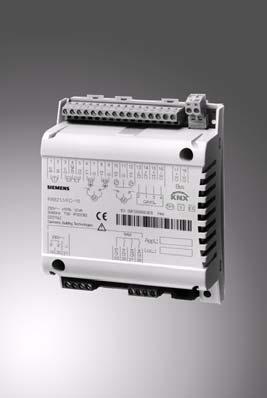
41 P01 RXB Room controllers For fan-coil applications FC-10, FC-11, FC12 with Konnex bus communications (S-mode and LTE mode) RXB21.1 RXB22.1 The RXB21.1 and RXB22.1 room controllers are used for temperature control in individual rooms. For 2-pipe or 4-pipe fan-coil systems, with or without change-over PI control Konnex bus communication (S-mode and LTE mode) Integration into the DESIGO building automation and control system via PX KNX Integration into Synco Control of AC 24 V PDM 1) thermic valve actuators, 3-position AC 24 V motorized valve and damper actuators, or electric heating coils Use of motorized KNX / EIB bus valves Volt-free relay contacts for control of fans and electric heating coils Commissioning with ETS3 Professional, Synco ACS or "HandyTool" AC 230 V operating voltage Plug-in screw terminals 1) PDM = Pulse Duration Modulation CM2N3873en_06 02 Apr 2010 Building Technologies
42 Application The RXB21.1 and RXB22.1 room controllers are optimized for control of fan-coil systems in individual rooms. The following options are available with fan-coil systems: RXB21.1: Single-speed to 3-speed automatic fan control RXB22.1: Single-speed to 3-speed automatic fan control with integrated relay for electric re-heater The application of each controller is determined by the application software. The controllers are delivered with a fixed set of applications, each of which contains various individual applications. The relevant application is selected and activated during commissioning using one of the following tools: ETS3 Professional (EIB / KNX Tool Software) Synco ACS "HandyTool" (the QAX34.3 room unit includes a tool function allowing you to parameterize the connected RXB controller). Use of spare inputs/outputs Some of the applications do not make full use of all the inputs and outputs. These I/Os can be used freely in conjunction with a building automation and control system to register digital signals, for example, or to control various items of equipment (ON/OFF or pulse control with AC 24 V or volt-free relay contacts). The inputs can then be read and the outputs controlled via the building automation and control system. Note Not suitable for time-critical processes <1 s. Functions The room controller functions are determined by the selected application and its parameters, and by the input/output configuration. For details, refer to the FNC description of functions, document CA When DESIGO RXB controllers are integrated into a building automation and control system, or into a Synco system, additional functions become available such as time scheduling, central control of setpoints, etc. 2/16 Siemens RXB21.1, RXB22.1 Room controllers CM2N3873en_06 Building Technologies 02 Apr 2010
43 Applications The following applications are available for the RXB2 room controllers: Application group (type) FC-10 (with RXB21.1) FC-11 (with RXB21.1) FC-12 (with RXB22.1) Fan-coil applications FNC02 FNC04 FNC08 FNC20 FNC10 FNC12 FNC18 FNC03 FNC05 2-pipe system with changeover 4-pipe system 4-pipe system and room/supply air cascade control 4-pipe system with single damper control 2-pipe system with changeover and outside air damper 4-pipe system with outside air damper 2-pipe system with changeover and radiator 2-pipe system with changeover and electric re-heater 4-pipe system with electric re-heater Note Only one application at a time can be activated with the tool (ETS3 Professional, Synco ACS or "HandyTool"). Types The RXB21.1 and RXB22.1 room controllers differ only in the number of outputs available: Type AC 24 V triac outputs Relay outputs RXB21.1 RXB22.1 For 2 thermic valve actuators or two 3-position actuators For 2 thermic valve actuators or one 3-position actuator For 3-speed fan control For 3-speed fan control internal relay for electric heating coil RXZ20.1 Accessories: Terminal covers Ordering When ordering please specify the quantity, product name, type code and application group. Example: 30 Room controllers, type RXB21.1/FC-10 Siemens RXB21.1, RXB22.1 Room controllers CM2N3873en_06 Building Technologies 02 Apr /16
44 Compatibility The RXB2 room controller is compatible with field devices from Siemens Building Technologies and with KNX / EIB-compatible third-party devices. For details, refer to the DESIGO RX hardware overview, CA2N3804. Design The RXB2... controllers consist of a housing base, a housing cover and the printed circuit board with connection terminals. The controllers also have a tool socket, a service LED and a programming pin. Plug-in connection terminals Cable restraints Plug-in connection terminals for KNX / EIB bus Housing cover 3873J01 Housing base Plug-in connection terminals Service LED Programming pin Tool socket Service LED The programming LED shows the operational status of the room controller as follows: Green flashing Red ON Orange / green flashing OFF Other patterns OK, device is in operation Addressing mode (ACS / ETS) Fault Parameter download No supply voltage Fault Service LED disabled by software Start-up (approx. 5.sec) Fault Programming pin The programming pin is used to identify the controller in the commissioning phase. Pressing this pin causes the red programming LED to light up and remain on until identification of the controller is complete. Once the programming pin has been pressed, the tool overwrites the hardware address in the room controller. If there are no terminal covers fitted, the programming pin may be operated only by a qualified electrician. The adjacent terminal may be a live mains voltage conductor. 4/16 Siemens RXB21.1, RXB22.1 Room controllers CM2N3873en_06 Building Technologies 02 Apr 2010
45 Terminal cover Terminal covers (RXZ20.1) are available as an option, to protect the connection terminals from physical contact and dirt. The programming LED remains visible when the terminal covers are in place, and the programming pin can be operated with a pointed implement. The cable is connected to the room controller by breaking out the perforated cable entry guide. 3873J02 Removing the terminal cover Label (example for RXB21.1) Identification number (unique serial number) ID in bar-code form, code Z04 Protection standard Temperature range (0 50 C) Serial No. Test date, series (Z, A, B, C ) Observe notes in this document B CA9900 Activated application Location Note Options for use of the labeling fields Appl. and Loc. : Handwritten identification of the location and the activated application group. Connection terminals All terminals are detachable plug-in screw-terminals. To avoid incorrect wiring, terminals which can be connected to AC 230 V (relay outputs) are physically separate from the other terminals. The cable restraints on the housing base must be used for the connections to terminals (AC 230 V). The conductors must be secured with cable ties (see diagram). 3873J04 Warning! Ensure that the power is off before inserting or removing plug-in terminals connected to a mains voltage. Siemens RXB21.1, RXB22.1 Room controllers CM2N3873en_06 Building Technologies 02 Apr /16
46 Communication The RXB2 controllers communicate with other devices via the following interfaces: PPS2 interface (proprietary) for the exchange of data with the room units KNX / EIB bus (terminals CE+ and CE-) for communication with: PX/KNX interface (to DESIGO INSIGHT) Interface OCI700 (to Synco) Other DESIGO RXB controllers KNX / EIB compatible field devices (e.g. temperature sensor) The tool socket (RJ45) must be connected only by a qualified electrician. The adjacent terminal may be a live mains voltage conductor. Connecting the tool To facilitate commissioning, the tools ETS3 Profession or Synco ACS can be connected at three different points (marked (A) in the diagram) in the plant: to the KNX / EIB bus cable at any point to the RXB2 controller (RJ45 tool socket) to the room unit (RJ45 tool socket) PPS2 KNX KNX bus A 3873A05 en CP CP+ C+ C QAX3... RXZ90.1 RXB2... CP CP+ CE+ CE CE+ CE A KNX RS232 V24 Siemens N148 / UP146 / UP152 ETS PPS2 B PPS2 Tool KNX A HandyTool QAX34.3 Siemens Anschlusskabel KNX PPS2 PPS2 B Tool KNX A HandyTool QAX34.3 Siemens Anschlusskabel A KNX USB Siemens OCI700 ETS / ACS Notes Caution! The tool socket is a proprietary socket. A Siemens connecting cable must be used (e.g. PXA-C1). When connected to Ethernet, the device on the other end may be damaged! The tools ETS3 and ACS, even if connected to a tool socket, require an interface: RS232 KNX/EIB interface (ETS3) OCI700 USB-KNX / EIB interface (ETS3, ACS). The "HandyTool" is connected to the tool socket of the room controller or to the tool socket of the room unit (QAX3, RXZ90.1) (B). If you use OCI700 as an interface, it is connected to the service plug of the controller or of the room unit. As long as the OCI700 is connected to the service plug, it must be supplied by the computer via the USB interface. Otherwise the LCD display of the room unit will turn dark and the controller will switch to addressing mode. 6/16 Siemens RXB21.1, RXB22.1 Room controllers CM2N3873en_06 Building Technologies 02 Apr 2010
47 Disposal The device is classified as waste electronic equipment in terms of the European Directive 2002/96/EC (WEEE) and should not be disposed of as unsorted municipal waste. The relevant national legal rules are to be adhered to. Regarding disposal, use the systems setup for collecting electronic waste. Observe all local and applicable laws. Engineering notes The KNX / EIB Building Services Management Manual and system principles supplement (see "Reference documentation", page 10) contains the information relevant for the engineering of the KNX / EIB bus (topology, bus repeaters, etc.) and for the selection and dimensions of connecting cables for the supply voltage and field devices. AC 230 V supply cables Volt-free relay outputs AC 230 V The RXB2 room controllers operate with a mains supply voltage of AC 230 V. The controlled devices (valves and damper actuators) receive their power directly from the room controller. This means that a separate AC 24 V supply is not necessary for the controllers and associated field devices. The sizing and fuse protection of the power supply cables depends on the total load and on local regulations. The power supply cables connected to the room controller must be secured with cable restraints. If serial wiring is applied on the terminal block 19/21, the connection will be interrupted if the block is removed from the controller (the jumpers and are on the PCB, not in the block, see terminal diagrams on pages 11 and 12) The supply cables must be secured with cable restraints. The volt-free relay outputs allow the switching of loads up to AC 250 V, 5 A (4 A). The heating coil relay in the RXB22.1 switches resistive loads up to 1.8 kw. The cable dimensions depend on the connected load and the local installation regulations. The circuits must be externally fused ( 10 A) as there are no internal fuses. The cables connected to the room controller must be secured with cable restraints. The fans must not be connected in parallel. AC 24 V triac outputs Example: The simultaneous load on outputs Y1 Y4 must not exceed 9.5 VA. Y1 (heating) 2 thermic valve actuators, type STP72E 5 W Y2 (cooling) 2 thermic valve actuators, type STP72E 5 W Y3, Y4 (outside air) 3-position damper actuator 4.5 VA 4.5 VA The maximum load is 9.5 VA for the heating sequence and 9.5 VA for the cooling sequence. This is acceptable because the two sequences never operate at the same time. With low loads (< 2VA) the voltage tolerance may be greater than +20% (see technical data). Siemens RXB21.1, RXB22.1 Room controllers CM2N3873en_06 Building Technologies 02 Apr /16
48 Mounting instructions The room controllers can be mounted in any orientation, and fixed as follows: 3873J J06 Rail mounting The housing base is designed for snapmounting on DIN rails, type EN x 7.5 (can be released with a screwdriver). Surface mounting There are two drill holes for screw-mounting (see Dimensions for drilling template). The housing base is fitted with raised supports. Screws: Max. diameter 3.5 mm, min. length 38 mm STOP Note! Tightening torque for fixing screws max. 1.5 Nm When mounting note the following: The controller should not be freely accessible after mounting. It must be mounted in a cabinet or behind a cover that can only be opened / removed with a key or a tool. Ensure adequate air circulation to dissipate heat generated during operation. Easy access is required for service personnel Local installation regulations must be observed. Mounting instructions and a drilling template are printed on the controller packaging. Commissioning The RXB2... room controllers are commissioned with either the ETS3 Professional or the Synco ACS tool via the RS232-KNX / EIB interface, or via the USB-KNX / EIB interface (OCI700), or with the HandyTool" via PPS2 Labeling Function test The definitive application and the controller's location are handwritten in the labeling fields "Appl." and "Loc" in the commissioning stage. A special test mode (ETS3 Professional or "HandyTool") is available for operation of the outputs. Further, if the digital inputs have been activated, they can be interrogated. 8/16 Siemens RXB21.1, RXB22.1 Room controllers CM2N3873en_06 Building Technologies 02 Apr 2010
49 In the event of a long-term short circuit (approx. 4 minutes) or overload, the thermal fuse in the transformer may trip. Subsequently, the device must be exchanged. There is no protection against accidental connection on the AC 24 V side. Mains AC 230 V for the supply and for the relays must be disconnected before plugging and unplugging the terminal blocks (danger of electric shock!) If serial wiring is applied on the terminal block 19/21, the connection will be interrupted if the block is removed from the controller (the jumpers and are on the PCB, not in the block, see terminal diagrams on pages 11 and 12). Technical data Power supply Operating voltage AC 230 V ± 10 % Rated voltage AC 230 Frequency 50/60 Hz Power consumption with connected field devices Max. 12 VA Internal fuse Thermal, non-resetting Operating data Control algorithm PI Inputs Signal inputs D1, D2 Quantity 2 (for volt-free contacts) Contact voltage DC 16 V Contact current DC 5 ma Contact transfer resistance Max. 100 Contact insulation resistance Min. 50 k Switch time: min. 20ms ON, min. 20ms OFF Measured value input B1 Compatible temperature sensors LG-Ni 1000 Quantity 1 measuring range C Sensor current 0.5 ma Resolution 0.1 K Measuring error at 25 C sensor temp. (without cable) max. 0.5 K Outputs AC24 V triac outputs, Y1 Y4 Quantity 2 (RXB22.1) 4 (RXB21.1) Output voltage AC 24 V ON/OFF, PWM or 3-position: +/ 20% (May exceed +20% with loads under 2VA) Output current Max. 0.5 A Total nominal load (at both outputs simultaneously) Max. 9.5 VA (e.g. 2 thermic valves, type STP72E per heating and cooling sequence + 1 damper actuator 4.5 VA) Relay outputs Q14, Q24, Q34 Quantity 3 Relay type Monostable Contact rating with AC voltage Switching voltage Max. AC 250 V, min. AC 19 V Nominal current, resistive/inductive Max. AC 5 A/4 A (cos = 0.6) Making current 200 ms half-time Max. 20 A Switching current at AC 29 V Min. AC 10 ma Contact rating with DC voltage Switching voltage Max. DC 250 V, min. DC 5 V Switching current at DC 5 V Min. DC 100 ma Switching capacity Max. 20 W Inductive load L/R Max. 7 ms Q44 Relay type Monostable Contact rating with AC voltage Max. admissible load (resistive only) Max. 1.8 kw External fuse (essential) Max. 10 A Siemens RXB21.1, RXB22.1 Room controllers CM2N3873en_06 Building Technologies 02 Apr /16
50 Ports/interfaces Interface to room unit Number of room units connectable 1 Interface type for room unit for ETS3 Professional / ACS PPS2 KNX / EIB bus PPS2 baud rate 4.8 kbit/s Baud rate on KNX / EIB bus 9.6 kbit/s KNX / EIB bus Interface type KNX / EIB (electrically isolated) Transceiver TP-UART Bus current 5 ma Baud rate 9.6 kbit/s Bus topology Refer to KNX / EIB manual (Reference documentation, see below) Cable connections Connection terminals for signals and power supply (plug-in screw terminals) Solid or stranded conductors mm 2 or 2 x 1.5 mm 2 KNX / EIB bus connection terminals (plug-in screw terminals) Solid or stranded conductors 2 x max.1.0 mm 2 e.g. YCYM 2x2x0.8 Single cable lengths For field devices, see also the RXB & RXL installation guide, CM Signal inputs D1, D2 Max. 100 m with diameters 0.6 mm Measured value input B1 Max. 100 m AC24 V triac outputs, Y1 Y4 Max. 100m where A 1.5 mm 2 Relay outputs Q14, Q24, Q34, Q44 Depends on load and local regulations Interface to room unit Max. 115 m where A= 0.75 mm 2 (including connecting cable for tool) Cable type 4-core, twisted pair, unscreened KNX / EIB bus Max. 500 m Cable type Refer to KNX / EIB manual (see "Reference documentation" below) Tool connecting cable Max. 3 m Housing protection standard Protection standard to EN IP30 with terminal cover fitted and wall mounted without DIN rail IP20 for all other mounting arrangements Protection class Suitable for use in systems with protection class I or II Ambient conditions Normal operation Class 3K5 to IEC Temperature C Humidity < 85 % rh Transport Class 2K3 to IEC Temperature C Humidity < 95 % rh Standards and directives Product safety Automatic electronic controls for household and similar use EN Electromagnetic compatibility Immunity (industrial & domestic) EN Emissions (domestic) EN Home and Building Electronic Systems (HBES) EN Electronic individual zone control equipment EN compliance Meets requirements of EMC Directive 2004/108/EG Low Voltage Directive 2006/95/EG C-Tick conformity (EMC) AS/NZS Konnex compliance Certified eu.bac: Meets the requirements for eu.bac License numbers 20856, certification as per the product list at: Reduction of hazardous substances 2002/95/EC Dimensions See dimension diagrams Weight excluding packaging 0,640 kg including packaging kg Reference documentation Building Services Management Manual Fundamental principles, and... Applications Zentralverband Elektrotechnik- und Elektronikindustrie e.v. (ZVEH) (Central association for the electrical and electronic engineering industry), Stresemannallee 19D Frankfurt a. M, Germany. 10/16 Siemens RXB21.1, RXB22.1 Room controllers CM2N3873en_06 Building Technologies 02 Apr 2010
51 Connection terminals RXB CP CP + CE + CE 3873A08 B1 M D1 GND D2 Y1 G Y2 T EIB / KNX M QAX... AC 230V Q13 Q14 Y3 G Y4 M AC 230V 5(4)A N N L L Q24 Q34 N.C. CE + CE Measured value input B1 1 Measured value input for LG-Ni 1000 sensors M 2 Measured value input ground Signal inputs D1 4 Signal input GND 5 Signal ground D2 6 Signal input Triac outputs Y1 7 AC 24 V, 0.5 A switching output G 8 AC 24 V actuator supply Y2 9 AC 24 V, 0.5 A switching output Y3 10 AC 24 V, 0.5 A switching output G 11 AC 24 V actuator supply Y4 12 AC 24 V, 0.5 A switching output Room unit CP 13 PPS2 ground CP+ 14 PPS2 data CE+ 15 KNX / EIB data cable CE 16 KNX / EIB data cable KNX / EIB bus (plug-in connection) CE+ 17 KNX / EIB data cable CE 18 KNX / EIB data cable Power supply N 19 Neutral conductor R 21 Phase conductor AC 230 V +/- 10 % Relay outputs Q13 25 Common feed for Q14, Q24 and Q34 Q14 26 Normally-open contact, max. AC 250 V, 5 (4) A (Stage 1) Q24 27 Normally-open contact, max. AC 250 V, 5 (4) A (Stage 2) Q34 28 Normally-open contact, max. AC 250 V, 5 (4) A (Stage 3) Caution Observe the technical data for the relay outputs: max. AC 250 V, 5 (4) A Local installation regulations must be observed. Tool socket Proprietary RJ45-type tool socket KNX / EIB data cable (CE+) 2 KNX / EIB data cable (CE ) 3 Not used 4 Not used 3206Z VDC 6 RxD 7 PPS2 (CP+) / TxD 8 PPS2 (CP ) Siemens RXB21.1, RXB22.1 Room controllers CM2N3873en_06 Building Technologies 02 Apr /16
52 Connection terminals RXB A09 T EIB / KNX M QAX... AC 230V AC 230V 10A AC 230V 5(4)A N N L L N.C. Q43 Q44 Q13 Q14 Q24 Q34 B1 M N.C. D1 GND D2 Y1 G Y2 N.C. N.C. N.C. CP CP + CE + CE CE + CE Measured value input B1 1 Measured value input for LG-Ni 1000 sensors M 2 Measured value input ground Signal inputs D1 4 Signal input GND 5 Signal ground D2 6 Signal input Triac outputs Y1 7 AC 24 V, 0.5 A switching output G 8 AC 24 V actuator supply Y2 9 AC 24 V, 0.5 A switching output Room unit CP 13 PPS2 ground CP+ 14 PPS2 data CE+ 15 KNX / EIB data cable CE 16 KNX / EIB data cable KNX / EIB bus (plug-in connection) CE+ 17 KNX / EIB data cable CE 18 KNX / EIB data cable Power supply N 19 Neutral conductor R 21 Phase conductor AC 230 V +/- 10 % Relay outputs Q13 25 Common feed for Q14, Q24 and Q34 Q14 26 Normally-open contact, max. AC 250 V, 5 (4) A (Stage 1) Q24 27 Normally-open contact, max. AC 250 V, 5 (4) A (Stage 2) Q34 28 Normally-open contact, max. AC 250 V, 5 (4) A (Stage 3) Q43 23 Lead wire for Q44 Q44 21 N/O contact AC max. 250 V, 10 A...(electric heating coil) Caution Observe the technical data for the relay outputs: Max. AC 250 V, 5 (4) A and 10 A, respectively Local installation regulations must be observed. Tool socket Proprietary RJ45-type tool socket KNX / EIB data cable (CE+) 2 KNX / EIB data cable (CE ) 3 Not used 4 Not used 3206Z VDC 6 RxD 7 PPS2 (CP+) / TxD 8 PPS2 (CP ) 12/16 Siemens RXB21.1, RXB22.1 Room controllers CM2N3873en_06 Building Technologies 02 Apr 2010
53 Connection diagrams Connection of field devices, room unit, KNX / EIB bus and power supply N1 B1 M D1 GND D T B1 D1 D2 3873A11 Y1 G Y Y1 Y2 GL M Y1.1 Y3 G Y Y3 Y4 GL M Y3.1 CP CP + CE + CE PPS2 KNX / EIB B2 CE + CE KNX / EIB N N L L N AC 230 V L N.C. Q43 Q Q2 L N Q13 Q14 Q24 Q Q1 L N L 1 N Q1.1 N1 RXB21.1, RXB22.1 B1 LG-Ni 1000 temperature sensor D1, D2 Volt-free contacts (window contact, occupancy sensor, etc.) Y1...Y4 AC 24 V thermic valve actuators Y1.1 Motorized AC 24 V, 3-position valve or damper actuator Y3.1 Motorized AC 24 V, 3-position valve or damper actuator B2 QAX room unit Q1 3-speed fan Q1.1 1-speed fan Q2 Electric heating coil Twisted pair Fans connected to relay outputs Q14 Q34 must not be operated in parallel. For parallel operation use cut-off relays or slave room controllers. At Q2 (1.8 kw max. resistive load), use additional external fuses of max. 10 A to protect the pcb tracks. Note For information on the compatibility of field devices with the RXB21.1 and RXB22.1 room controller, refer to the various application descriptions (see the FNC description of functions, document CA110385) Siemens RXB21.1, RXB22.1 Room controllers CM2N3873en_06 Building Technologies 02 Apr /16
54 Parallel connection of several thermic valve actuators Up to two thermic actuators per sequence may be connected directly to the room controller. With more than two thermic actuators, a UA1T power amplifier is required. The principle is the same for output Y2. Do not exceed the maximum simultaneous load on outputs Y1 and Y2 (max. 9.5 VA). Power consumption at input X1 of the UA1T: 0.5 VA. Mixed operation: It is not permissible to connect thermic actuators both to the controller and to the power amplifier. Owing to the difference in voltage between the controller's internal transformer and the power supply of the UA1T, this could cause the valve positions to deviate substantially. Connection to the controller N1 L N L N AC 230 V Y1 G Y1 Y Z12 Connection to the power amplifier N1 AC 230 V L N AC 24 V G G0 3873Z13 L N Y1 G Y1 N2 1 NS COM 8 Y1.1 Y LS COM Y1 COM 7 6 Y1.2 Y1.4 4 X1 Y1 5 N2 1 NS COM 8 Y1.5 Y LS COM Y1 COM 7 6 Y1.6 Y1.8 4 X1 Y1 5 N1 N2 Y1 Y1.x Room controller RXB21.1, RXB22.1 UA1T power amplifier (see data sheet CA2N3591) AC 24 V thermic valve actuators connected to the controller AC 24 V thermic valve actuators (max. 2 STA72E / STP72E actuators per Y1 output on the UA1T) Notes The UA1T requires an AC 24 V supply voltage The UA1T is not suitable for the connection of 3-position actuators. 14/16 Siemens RXB21.1, RXB22.1 Room controllers CM2N3873en_06 Building Technologies 02 Apr 2010
55 Dimensions Dimensions in mm Without terminal cover 3873M14 35,3 3, ,3 133,2 4,4 With terminal covers 51,5 5 35, M15 3, ,4 107,8 Siemens RXB21.1, RXB22.1 Room controllers CM2N3873en_06 Building Technologies 02 Apr /16
56 Drilling diagram (1:1) 3,6 3873M ,2 86, Siemens Switzerland Ltd. Subject to alteration 16/16 Siemens RXB21.1, RXB22.1 Room controllers CM2N3873en_06 Building Technologies 02 Apr 2010

57 s RXB Room controller For chilled ceiling and radiator applications CC-02 with Konnex bus communications (S-mode and LTE mode) RXB24.1 The RXB24.1 room controller is used for temperature control in individual rooms. For chilled ceiling and radiator systems PI control Konnex bus communication (S-mode and LTE mode) Integration into the DESIGO building automation and control system via PX KNX Integration into Synco Control of AC 24 V PDM 1) thermic valve actuators or 3-position AC 24 V motorized valve actuators Use of motorized KNX / EIB bus valves Commissioning with ETS3 Professional, Synco ACS or "HandyTool" AC 230 V operating voltage Plug-in screw terminals 1) PDM = Pulse Duration Modulation CM2N3874en_04 02 Apr 2010 Building Technologies
58 Application The RXB24.1 room controller is optimized for control of chilled ceiling and radiator systems in individual rooms. The application of each controller is determined by the application software. The controllers are delivered with a fixed set of applications, each of which contains various individual applications. The relevant application is selected and activated during commissioning using one of the following tools: ETS3 Professional (EIB / KNX Tool Software) Synco ACS "HandyTool" (the QAX34.3 room unit includes a tool function allowing you to parameterize the connected RXB controller). Use of spare inputs/outputs Some of the applications do not make full use of all the inputs and outputs. These I/Os can be used freely in conjunction with a building automation and control system to register digital signals, for example, or to control various items of equipment (ON/OFF or pulse control with AC 24 V). The inputs can then be read and the outputs controlled via the building automation and control system. Note Not suitable for time-critical processes <1 s. Functions The room controller functions are determined by the selected application and its parameters, and by the input/output configuration. For details, refer to the CLC and RAD description of functions, document CA When DESIGO RXB controllers are integrated into a building automation and control system, or into a Synco system, additional functions become available such as time scheduling, central control of setpoints, etc. Applications The following applications are available for the RXB24.1 room controllers: Application group (type) CC-02 (with RXB24.1) Applications CLC01 CLC02 RAD01 Chilled ceiling with dew point monitoring Chilled ceiling with dew point monitoring, radiator with downdraft compensation Radiator with downdraft compensation Note Only one application at a time can be activated with the tool (ETS3 Professional, Synco ACS or "HandyTool"). 2 / 16 Siemens RXB24.1 Room controller CM2N3874en_04 Building Technologies 02 Apr 2010
59 Types The RXB24.1 room controller has the following outputs: Type RXB24.1 RXZ20.1 AC 24 V triac outputs For 2 thermic valve actuators or two 3-position actuators Accessories: Terminal covers Ordering When ordering please specify the quantity, product name, type code and application group. Example: 30 Room controllers, type RXB24.1/CC-02 Compatibility The RXB24.1 room controller is compatible with field devices from Siemens Building Technologies and with KNX / EIB-compatible third-party devices. For details, refer to the DESIGO RX hardware overview, CA2N3804. Design The RXB24.1 controller consists of a housing base, a housing cover and the printed circuit board with connection terminals. The controller also has a tool socket, a service LED and a programming pin. Plug-in connection terminals Housing cover 3873J01 Cable restraints Plug-in connection terminals for KNX / EIB bus Housing base Plug-in connection terminals Service LED Programming pin Tool socket Siemens RXB24.1 Room controller CM2N3874en_04 Building Technologies 02 Apr / 16
60 Service LED The programming LED shows the operational status of the room controller as follows: Green flashing Red ON Orange / green flashing OFF Other patterns OK, device is in operation Addressing mode (ACS / ETS) Fault Parameter download No supply voltage Fault Service LED disabled by software Start-up (approx. 5.sec) Fault Programming pin The programming pin is used to identify the controller in the commissioning phase. Pressing this pin causes the red programming LED to light up and remain on until identification of the controller is complete. Once the programming pin has been pressed, the tool overwrites the hardware address in the room controller. If there are no terminal covers fitted, the programming pin may be operated only by a qualified electrician. The adjacent terminal may be a live mains voltage conductor. Terminal cover Terminal covers (RXZ20.1) are available as an option, to protect the connection terminals from physical contact and dirt. The programming LED remains visible when the terminal covers are in place, and the programming pin can be operated with a pointed implement. The cable is connected to the room controller by breaking out the perforated cable entry guide. 3873J02 Removing the terminal cover 4 / 16 Siemens RXB24.1 Room controller CM2N3874en_04 Building Technologies 02 Apr 2010
61 Label Identification number (unique serial number) ID in bar-code form, code Z04 Protection standard Temperature range (0 50 C) Serial No. Test date, series (Z, A, B, C ) Observe notes in this document B CA9900 Activated application Location Note Options for use of the labeling fields Appl. and Loc. : Handwritten identification of the location and the activated application group. Connection terminals All terminals are detachable plug-in screw-terminals. To avoid incorrect wiring, terminals which can be connected to AC 230 V are physically separate from the other terminals. The cable restraints on the housing base must be used for the connections to terminals (AC 230 V). The conductors must be secured with cable ties (see diagram). 3873J04 Warning! Ensure that the power is off before inserting or removing plug-in terminals connected to a mains voltage. Communication The RXB24.1 controller communicates with other devices via the following interfaces: PPS2 interface (proprietary) for the exchange of data with the room units KNX / EIB bus (terminals CE+ and CE-) for communication with: PX/KNX interface (to DESIGO INSIGHT) Interface OCI700 (to Synco) Other DESIGO RXB controllers KNX / EIB compatible field devices (e.g. temperature sensor) Siemens RXB24.1 Room controller CM2N3874en_04 Building Technologies 02 Apr / 16
62 Connecting the tool To facilitate commissioning, the tools ETS3 Profession or Synco ACS can be connected at three different points (marked (A) in the diagram) in the plant: to the KNX / EIB bus cable at any point to the RXB2 controller (RJ45 tool socket) to the room unit (RJ45 tool socket) PPS2 KNX KNX bus A 3873A05 en CP CP+ C+ C QAX3... RXZ90.1 RXB2... CP CP+ CE+ CE CE+ CE A KNX RS232 V24 Siemens N148 / UP146 / UP152 ETS PPS2 B PPS2 Tool KNX A HandyTool QAX34.3 Siemens connecting cable KNX PPS2 PPS2 B Tool KNX A HandyTool QAX34.3 A Siemens connecting cable KNX USB Siemens OCI700 ETS / ACS Notes Caution! The tool socket is a proprietary socket. A Siemens connecting cable must be used (e.g. PXA-C1). When connected to Ethernet, the device on the other end may be damaged! The tools ETS3 and ACS, even if connected to a tool socket, require an interface: RS232 KNX/EIB interface (ETS3) OCI700 USB-KNX / EIB interface (ETS3, ACS). The "HandyTool" is connected to the tool socket of the room controller or to the tool socket of the room unit (QAX3, RXZ90.1) (B). If you use OCI700 as an interface, it is connected to the service plug of the controller or of the room unit. As long as the OCI700 is connected to the service plug, it must be supplied by the computer via the USB interface. Otherwise the LCD display of the room unit will turn dark and the controller will switch to addressing mode. Disposal The device is classified as waste electronic equipment in terms of the European Directive 2002/96/EC (WEEE) and should not be disposed of as unsorted municipal waste. The relevant national legal rules are to be adhered to. Regarding disposal, use the systems setup for collecting electronic waste. Observe all local and applicable laws. 6 / 16 Siemens RXB24.1 Room controller CM2N3874en_04 Building Technologies 02 Apr 2010
63 Engineering notes The KNX / EIB Building Services Management Manual and system principles supplement (see "Reference documentation ", page 10) contains the information relevant for the engineering of the KNX / EIB bus (topology, bus repeaters, etc.) and for the selection and dimensions of connecting cables for the supply voltage and field devices. AC 230 V supply cables The RXB24.1 room controller operates with a mains supply voltage of AC 230 V. The controlled devices (valve actuators) receive their power directly from the room controller. This means that a separate AC 24 V supply is not necessary for the controllers and associated field devices. The sizing and fuse protection of the power supply cables depends on the total load and on local regulations. The power supply cables connected to the room controller must be secured with cable restraints. If serial wiring is applied on the terminal block 19/21, the connection will be interrupted if the block is removed from the controller (the jumpers and are on the PCB, not in the block, see terminal diagrams on pages 11 and 12) The supply cables must be secured with cable restraints. AC 24 V triac outputs The simultaneous load on outputs Y1 Y4 must not exceed 9.5 VA. Example: Y1 (heating) Y2 (cooling) 2 thermic valve actuators, type STP72E / STA72E 5 W 2 thermic valve actuators, type STP72E / STA72E 5 W The maximum load is 9.5 VA for the heating sequence and 9.5 VA for the cooling sequence. This is acceptable because the two sequences never operate at the same time. With low loads (< 2VA) the voltage tolerance may be greater than +20% (see technical data). Siemens RXB24.1 Room controller CM2N3874en_04 Building Technologies 02 Apr / 16
64 Mounting instructions The room controllers can be mounted in any orientation, and fixed as follows: 3873J J06 Rail mounting The housing base is designed for snapmounting on DIN rails, type EN x 7.5 (can be released with a screwdriver). Surface mounting There are two drill holes for screw-mounting (see Dimensions for drilling template). The housing base is fitted with raised supports. Screws: Max. diameter 3.5 mm, min. length 38 mm STOP Note! Tightening torque for fixing screws max. 1.5 Nm When mounting note the following: The controller should not be freely accessible after mounting. It must be mounted in a cabinet or behind a cover that can only be opened / removed with a key or a tool. Ensure adequate air circulation to dissipate heat generated during operation. Easy access is required for service personnel Local installation regulations must be observed. Mounting instructions and a drilling template are printed on the controller packaging. Commissioning The RXB24.1 room controller is commissioned with either the ETS3 Professional or the Synco ACS tool via the RS232-KNX / EIB interface, or via the USB-KNX / EIB interface (OCI700), or with the HandyTool" via PPS2 Labeling Function test The definitive application and the controller's location are handwritten in the labeling fields "Appl." and "Loc" in the commissioning stage. A special test mode (ETS3 Professional and HandyTool) is available for operation of the outputs and interrogation of the inputs. 8 / 16 Siemens RXB24.1 Room controller CM2N3874en_04 Building Technologies 02 Apr 2010
65 In the event of a long-term short circuit (approx. 4 minutes) or overload, the thermal fuse in the transformer may trip. Subsequently, the device must be exchanged. There is no protection against accidental connection on the AC 24 V side. Mains AC 230 V for the supply must be disconnected before plugging and unplugging the terminal blocks (danger of electric shock!) If serial wiring is applied on the terminal block 19/21, the connection will be interrupted if the block is removed from the controller (the jumpers and are on the PCB, not in the block, see terminal diagrams on pages 11 and 12). Technical data Power supply Operating voltage AC 230 V ± 10 % Rated voltage AC 230 V Frequency 50/60 Hz Power consumption with connected field devices Max. 12 VA Internal fuse Thermal, non-resetting Operating data Control algorithm PI Inputs Signal inputs D1, D2 Quantity 2 (for volt-free contacts) Contact voltage DC 16 V Contact current DC 5 ma Contact transfer resistance Max. 100 Contact insulation resistance Min. 50 k Switch time: min. 20ms ON, min. 20ms OFF Measured value input B1 Compatible temperature sensors LG-Ni 1000 Quantity 1 measuring range C Sensor current 0.5 ma Resolution 0.1 K Measuring error at 25 C sensor temp. (without cable) max. 0.5 K Outputs AC24 V triac outputs, Y1 Y4 Quantity 4 Output voltage AC 24 V ON/OFF, PWM or 3-position: +/ 20% (May exceed +20% with loads under 2VA) Output current Max. 0.5 A Total nominal load (at both outputs simultaneously) Max. 9.5 VA (e.g. 2 thermic actuators, type STP72E per heating and cooling sequence Ports/interfaces Interface to room unit Number of room units connectable 1 Interface type for room unit for ETS3 Professional / ACS PPS2 KNX / EIB bus PPS2 baud rate 4.8 kbit/s Baud rate on KNX / EIB bus 9.6 kbit/s KNX / EIB bus Interface type KNX / EIB (electrically isolated) Transceiver TP-UART Bus current 5 ma Baud rate 9.6 kbit/s Bus topology Refer to KNX / EIB manual (Reference documentation, see next page) Siemens RXB24.1 Room controller CM2N3874en_04 Building Technologies 02 Apr / 16
66 Cable connections Connection terminals for signals and power supply (plug-in screw terminals) KNX / EIB bus connection terminals (plug-in screw terminals) Single cable lengths Solid or stranded conductors mm 2 or 2 x 1.5 mm 2 Solid or stranded conductors 2 x max.1.0 mm 2 e.g. YCYM 2x2x0.8 For field devices, see also the RXB & RXL installation guide, CM Max. 100 m with diameters 0.6 mm Max. 100 m Signal inputs D1, D2 Measured value input B1 AC24 V triac outputs, Y1 Y4 Max. 100m where A 1.5 mm 2 Interface to room unit Max. 115 m where A= 0.75 mm 2 Cable type KNX / EIB bus Cable type Tool connecting cable (including connecting cable for tool) 4-core, twisted pair, unscreened Max. 500 m Refer to KNX / EIB manual (see "Reference documentation" below) Max. 3 m Housing protection standard Protection standard to EN IP30 with terminal cover fitted and wall mounted without DIN rail IP20 for all other mounting arrangements Protection class Suitable for use in systems with protection class I or II Ambient conditions Normal operation Class 3K5 to IEC Temperature C Humidity < 85 % rh Transport Class 2K3 to IEC Temperature C Humidity < 95 % rh Standards and directives Product safety Automatic electronic controls for household and similar use EN Electromagnetic compatibility Immunity (industrial & domestic) EN Emissions (domestic) EN Home and Building Electronic Systems (HBES) EN Electronic individual zone control equipment EN compliance Meets requirements of EMC Directive 2004/108/EC Low Voltage Directive 2006/95/EC C-Tick conformity (EMC) AS/NZS Konnex compliance Certified eu.bac: Meets the requirements for eu.bac certification License numbers as per the product list at: Reduction of hazardous substances 2002/95/EC Dimensions See dimension diagrams Weight excluding packaging 0,610 kg including packaging kg Reference documentation Building Services Management Manual Fundamental principles Building Services Management Manual Applications Zentralverband Elektrotechnik- und Elektronikindustrie e.v. (ZVEH) (Central association for the electrical and electronic engineering industry) Stresemannallee 19D Frankfurt a. M, Germany. 10 / 16 Siemens RXB24.1 Room controller CM2N3874en_04 Building Technologies 02 Apr 2010
67 Connection terminals RXB CP CP + CE + CE 3874A08 B1 M D1 GND D2 Y1 G Y2 Y3 G Y4 T EIB / KNX M M QAX... AC 230V N N L L N.C. CE + CE Measured value input B1 1 Measured value input for LG-Ni 1000 sensors M 2 Measured value input ground Signal inputs D1 4 Signal input GND 5 Signal ground D2 6 Signal input Triac outputs Y1 7 AC 24 V, 0.5 A switching output G 8 AC 24 V actuator supply Y2 9 AC 24 V, 0.5 A switching output Y3 10 AC 24 V, 0.5 A switching output G 11 AC 24 V actuator supply Y4 12 AC 24 V, 0.5 A switching output Room unit CP 13 PPS2 ground CP+ 14 PPS2 data CE+ 15 KNX / EIB data cable CE 16 KNX / EIB data cable KNX / EIB bus (plug-in connection) CE+ 17 KNX / EIB data cable CE 18 KNX / EIB data cable Power supply N 19 Neutral conductor R 21 Phase conductor AC 230 V +/- 10 % Caution Local installation regulations must be observed. Tool socket Proprietary RJ45-type tool socket KNX / EIB data cable (CE+) 2 KNX / EIB data cable (CE ) 3 Not used 4 Not used 3206Z VDC 6 RxD 7 PPS2 (CP+) / TxD 8 PPS2 (CP ) 11 / 16 Siemens RXB24.1 Room controller CM2N3874en_04 Building Technologies 02 Apr 2010
68 Connection diagrams Connection of field devices, room unit, KNX / EIB bus and power supply N1 B1 M 1 2 T B1 3874A11 D1 4 D1 GND 5 D2 6 D2 Y1 7 Y1 G Y2 8 9 Y2 GL M Y1.1 Y3 G Y3 GL M Y2.1 Y4 12 Y4 CP CP + CE + CE PPS2 KNX / EIB B2 CE + CE KNX / EIB N N L L N L AC 230 V N1 RXB24.1 B1 LG-Ni 1000 temperature sensor D1, D2 Volt-free contacts (window contact, occupancy sensor, etc.) Y1...Y4 AC 24 V thermic valve actuators Y1.1 Motorized AC 24 V, 3-position valve actuator Y2.1 Motorized AC 24 V, 3-position valve actuator B2 QAX room unit Twisted pair Note For information on the compatibility of field devices with the RXB24.1 room controller, refer to the various application descriptions (see the CLC and RAD description of functions, document CA110384) 12 / 16 Siemens RXB24.1 Room controller CM2N3874en_04 Building Technologies 02 Apr 2010
69 Parallel connection of several thermic valve actuators Up to two thermic actuators per sequence may be connected directly to the room controller. With more than two thermic actuators, a UA1T power amplifier is required. The principle is the same for output Y2. Do not exceed the maximum simultaneous load on outputs Y1 and Y2 (max. 9.5 VA). Power consumption at input X1 of the UA1T: 0.5 VA. Mixed operation: It is not permissible to connect thermic actuators both to the controller and to the power amplifier. Owing to the difference in voltage between the controller's internal transformer and the power supply of the UA1T, this could cause the valve positions to deviate substantially. Connection to the controller N1 L N L N AC 230 V Y1 G Y1 Y Z12 Connection to the power amplifier N1 AC 230 V L N AC 24 V G G0 3873Z13 L N Y1 G Y1 N2 1 NS COM 8 Y1.1 Y LS COM Y1 COM 7 6 Y1.2 Y1.4 4 X1 Y1 5 N2 1 NS COM 8 Y1.5 Y LS COM Y1 COM 7 6 Y1.6 Y1.8 4 X1 Y1 5 N1 N2 Y1 Y1.x Room controller RXB24.1 UA1T power amplifier (see data sheet CA2N3591) AC 24 V thermic valve actuators connected to the controller AC 24 V thermic valve actuators (max. 2 STA72E/STP72E actuators per Y1 output on the UA1T) Notes The UA1T requires an AC 24 V supply voltage The UA1T is not suitable for the connection of 3-position actuators. 13 / 16 Siemens RXB24.1 Room controller CM2N3874en_04 Building Technologies 02 Apr 2010
70 Dimensions Dimensions in mm Without terminal cover 3873M14 35,3 3, ,3 133,2 4,4 With terminal covers 51,5 5 35, M15 3, ,4 107,8 14 / 16 Siemens RXB24.1 Room controller CM2N3874en_04 Building Technologies 02 Apr 2010
71 Drilling diagram (1:1) 3,6 3873M ,2 86,3 15 / 16 Siemens RXB24.1 Room controller CM2N3874en_04 Building Technologies 02 Apr 2010
72 16 / Siemens Switzerland Ltd. Subject to change Siemens RXB24.1 Room controller CM2N3874en_04 Building Technologies 02 Apr 2010
73 s P01 DESIGO RX Room unit with PPS2 interface For use with: QAX34.3 Equipment from the RXC, RXB, RXL and RXA (PPS2) ranges DESIGO PX automation stations 1) Devices with a PPS2 interface Measurement of the room temperature Bias switch for adjustment of the room temperature setpoint Bias switch for selection of the operating mode ( /Auto) and for manual control of the fan in fan-coil systems (up to 3 speeds) LCD for display of room temperature and operating mode PPS2 interface to the controller Tool function for parameter setting and testing 2) of RXB/RXL controllers Application As a room unit: The room unit is used in rooms controlled by an individual room control system, to measure the room temperature and for operation of a room controller. The functions of the LCD display are determined by the controller. If manual fan-speed control is enabled, the room unit can be used to operate a fan-coil system. It is also suitable for use in conjunction with a DESIGO PX automation station 1). As a tool: In conjunction with the RXB / RXL controllers (FC-10 and later, CC-02) the QAX34.3 room unit can also be used for parameter-setting and for the wiring test 2). For details refer to the technical manual, CM (RXB), CM (RXL). 1) In the QAX34.3 room unit the address (fixed to 1) cannot be changed. If it is used with a PXC... automation station, the display shows the state requested by the user (see page 3), rather than the actual state. 2) Wiring test only available with devices from index D (inside the housing, se page 2). CM2N1640en_04 30 Jun 2009 Building Technologies
 ). 1) The QAX34.3 room unit only works with Address 1.")


74 Ordering When ordering, please specify the quantity, product name and type code. Example: 30 Room units QAX34.3 Compatibility The room unit can be used with all controllers incorporating a PPS2 room unit interface (e.g. DESIGO RX and DESIGO PX 1) ). 1) The QAX34.3 room unit only works with Address 1. If it is used with a PXC... automation station, the display shows the state requested by the user, rather than the actual state. Mechanical design The room unit is suitable for mounting on a recessed conduit box. The cable entry is through the rear. For surface mounting, with the cable entry at the top or bottom, accessory ARG70.2 is required. Basically the unit comprises the housing and the mounting plate. These can be locked together and released by a snap-mechanism. The mounting plate incorporates the screw terminals. The housing accommodates a printed circuit board, room temperature sensor element, bias switches for setpoint adjustment and selection of the operating mode and fan speed, and the LCD panel. The housing and mounting plate are plastic. Opening the housing 1 2 Index and manufacturing date 2/8 Siemens QAX34.3 Room unit with PPS2 interface CM2N1640en_04 Building Technologies 30 Jun 2009
75 Operator controls and display panel Display of actual room temperature or adjustment value, and bar indicating sequence (heating/cooling), operating mode and fan speed. Buttons for room temperature and setpoint adjustment Symbols for operating mode and fan speed Buttons for operating mode and fan speed Symbols for the sequence (heating/cooling) 1640Z03 Note The controller determines the actual functions of the buttons and display (based on the selected application and the associated parameters). The following describes all the functions of the elements illustrated. Button for selecting the operating mode and fan speed This button can be used like an occupancy button to determine the operating mode. Three manual fan speeds can also be defined. Pressing the left arrow once selects the option one step to the left, and pressing the right arrow once selects the option one step to the right. The currently active operating mode or the manually selected fan speed is indicated by a bar above the relevant symbol. Button for adjusting the room temperature setpoint When the button is pressed for the first time, the LCD display switches from room temperature to setpoint display. Each additional operation of the upper or lower button increases or reduces the setpoint by 0.5 K or 1.0 F (the engineering unit is predetermined by the controller). The maximum possible adjustment range is also defined by the controller. LCD panel The following display options are possible in normal operation (actual options determined by the controller). For details refer to the application description for the controller range concerned. For information on parameter-setting refer to the technical manual, documents CM (RXB) and CM (RXL). Room temperature in C (resolution 0.5 C) Room temperature in F (resolution 1.0 F) Setpoint adjustment displayed in digits (Displayed only while adjusting the relative setpoint) Scale and digits (Displayed only when adjusting the absolute setpoint) Cooling sequence is active Heating sequence (If the bar is not shown against either sequence, then the controller is operating the dead band) Economy operating mode Automatic fan control Comfort operating mode Automatic fan control Comfort operating mode Manual fan control, fan speed 1 Siemens QAX34.3 Room unit with PPS2 interface CM2N1640en_04 Building Technologies 30 Jun /8
76 Engineering notes The room unit receives its power from the connected controller via the PPS2 interface (low voltage, SELV). Only one room unit can be connected to an RX... room controller. When connecting a room unit to a PXC automation station, the room unit must be Address 1 (this address is permanently programmed in the room unit). The room unit must be connected to the room controller with a two-core twisted pair cable. See the relevant installation guide (RXC: CA110334; RXB & RXL: CM110381; RXA: CA2Z3884). Unscreened cable may be used. Mounting instructions The device is suitable both for surface mounting and for installation in a recessed conduit box The unit should not be mounted in recesses, shelving, behind curtains or doors or above or near direct heat sources Avoid direct sun and draughts The conduit must be sealed on the device side, as currents of air in the conduit can affect the sensor reading The admissible ambient conditions must be observed. Mounting instructions are enclosed with the device. A set of fixing accessories is enclosed with the device. Installation Local installation regulations must be observed. STOP Warning The equipment is not protected against accidental connection to AC 230 V. Commissioning Start-up characteristics After an interruption of the connection to the PPS2 interface, communication is only re-established when the connected room controller next polls the PPS2 addresses. The cycle times are as follows: RXA: 10 seconds; RXB, RXL, and RXC: 3 minutes; PX: 30 seconds When the supply voltage is connected (via the PPS2 interface) or in the event of a reset via the room controller, the following routine is executed in the room unit: Step Function Description 1 LCD test All segments of the display module are operated for approx. 3 s 2 Identification by controller 3 Ready for operation Until the controller recognizes the room unit as a PPS2 user, the display reads: 1 s after recognition by the controller, the room unit is ready for operation 4/8 Siemens QAX34.3 Room unit with PPS2 interface CM2N1640en_04 Building Technologies 30 Jun 2009
77 Displaying the Wink function of KNX/EIB and LONWORKS devices If the room unit is connected to a room controller in the DESIGO RXB, RXL or RXC range, the display can be used as an aid to commissioning. If the commissioning tool is used to transmit a Wink command, the room unit displays the type of room controller connected. For example: Room controller type RXB 21.1, RXL21,1, RXC21.1, RXC30.1 Display Operating notes During commissioning and operation, the LCD panel displays error messages: Display Description Type of error C: No communication with controller for over 64 s D 02: Firmware version (e.g. Version 2.0) Room temperature sensor outside range 0 40 C The room controller has not yet added the room unit to its list of members (during controller start-up) The room controller does not recognize room unit type Initial value, after room unit is switched on and before a room controller has sent a value. Room controller has not transmitted a valid temperature value S D D S S S Static error: The error display remains valid until the error has been cleared. D Dynamic error: For 5 s after its occurrence, the error is displayed instead of the room temperature. The display then reverts to normal. If the error persists, it can be displayed again by pressing the + or button. Pressing the button again implements a setpoint adjustment. All other error codes indicate a hardware error. Disposal The device is classified as waste electronic equipment in terms of the European Directive 2002/96/EC (WEEE) and should not be disposed of as unsorted municipal waste. The relevant national legal rules are to be adhered to. Regarding disposal, use the systems setup for collecting electronic waste. Observe all local and applicable laws. Technical data Supply voltage Operating voltage range SELV / PELV DC V The device receives its power from the connected controller via the PPS2 interface Power consumption (from controller) Max VA Siemens QAX34.3 Room unit with PPS2 interface CM2N1640en_04 Building Technologies 30 Jun /8
78 Operating data Temperature sensor Measuring element NTC resistance sensor Measuring range C Response time 10 min Measuring accuracy (5 30 C) 1.0 K Measuring accuracy (25 C) 0.5 K Setpoint correction Correction range (defined by controller) Max. 10 K (basic setting 3 K) Accuracy over full correction range 10 % Display Type LCD Functions displayed Room temperature Setpoint adjustment Operating mode ( / Auto) Manually selected fan speed Control sequence Type of error RXB/RXL parameter setting Ports/interfaces Type of port between controller and room unit PPS2 (point-to-point interface, V 2) Signal voltage, logic 0 < 5 V Signal voltage, logic 1 > 7 V Baud rate 4.8 kbps Cable connections Connection terminals (screw terminals) Solid or stranded conductors mm 2 Single cable length between controller and room unit See installation guides: DESIGO RXC: CA110334, DESIGO RXB & RXL: CM DESIGO RXA: CA2Z3884 DESIGO PX: CA Cable type 2-core, twisted pair, unscreened Housing protection Protection standard to EN IP 30 Protection class Insulation protection class III Ambient conditions IEC 721 Normal operation Transport Environmental conditions Class 3K5 Class 2K3 Temperature C C Humidity < 85 % rh < 95 % rh Mechanical conditions Class 3M2 Class 2M2 Standards and directives Product standard Automatic electronic controls for household and similar use EN Electromagnetic compatibility Immunity (industrial & domestic) EN Emissions (domestic) EN compliance Meets requirements of EMC directive 2004/108/EC C-Tick conformity (EMC) AS/NZS Environmental compatibility Dimensions The product environmental declaration CE1E1640 contains data on RoHS compliance, materials composition, packaging, environmental benefit, disposal See Dimensions ISO (Environment) ISO 9001 (Quality) 2002/95/EC (RoHS) Color Front plate NCS S 0502-G RAL 9003 signal white Housing base, mounting plate and bias switches RAL 7035 (light gray) Weight Excluding packaging kg 6/8 Siemens QAX34.3 Room unit with PPS2 interface CM2N1640en_04 Building Technologies 30 Jun 2009
79 Electrical connections Terminal layout PPS2 interface, power supply CP+ 1 Device power supply, PPS2 data (positive) CP 2 Device power supply, PPS2 data (negative) 1640A04 CP+ CP Wiring diagram The example below shows the room unit connected to a DESIGO RXB room controller. 1 2 CP+ CP R1 CP CP+ N1 PPS2 1640A05 = Twisted pair R1 N1 QAX34.3 room unit RXB room controller Siemens QAX34.3 Room unit with PPS2 interface CM2N1640en_04 Building Technologies 30 Jun /8
80 Dimensions Dimensions in mm , ,8 11, , M07 8/ Siemens Switzerland Ltd. Subject to change Siemens QAX34.3 Room unit with PPS2 interface CM2N1640en_04 Building Technologies 30 Jun 2009
81 RXB (KNX) applications library CLC and RAD description of functions for CC-02 (CLC and RAD applications: see document CM110671). Related documents CM1Y9775 CM1Y9776 CM1Y9777 CM1Y9779 RXB integration, S-mode. RXB / RXL integration Individual addressing. Third-party integration. Working with ETS. CM110384en_03 28 Feb 2009 Siemens Building Technologies
82 Table of contents 1 Introduction Revision history Copyright Quality assurance Document use / request to the reader Target audience, prerequisites Bus supply for RXB Konnex controllers RXB Konnex controller communications S-mode LTE mode Definitions / Tools Signals and parameters (presentation) Supported tools Parameterization with ETS3 Professional Parameterization using ACS Parameterization using the HandyTool Operating HandyTool functions Minor parameterization using room unit QAX Major parameterization using room unit QAX Select the device address using room unit QAX Upload/download parameters using room unit QAX Test the periphery using room unit QAX Select communications mode Address zones in LTE mode (together with Synco) RXB application example with RMB795 for geographical and time switch zones Implement application example Heating and refrigeration demand zones Applications / Parameters Select application Parameter settings Room operating modes Description Overview Determine the room operating mode with DESIGO (S-mode) Local control of room operating mode via a window contact Central control of room operating mode via input from the Use schedule Central and local control of room operating mode based on occupancy Central control of room operating mode via room operating mode schedule Local control of room operating mode with a room unit Local control of room operating mode via the Temporary Comfort mode input Effective room operating mode DESIGO examples Determine the room operating mode with third-party products (S-mode) Local control of room operating mode via window contact input Central control of room operating mode with an input from the room operating mode schedule Central control of the room operating mode via the schedules Use and Occupancy Central and local control of room operating mode based on occupancy Local control of room operating mode with a room unit Local control of room operating mode via the Temporary Comfort mode input Effective room operating mode /140 Siemens RXB (KNX) Applications library CLC and RAD description of functions for CC-02 CM110384en_03 Building Technologies Contents 28 Feb 2009
83 5.4.8 Third-party (S-mode) examples Determine the room operating mode with Synco (LTE mode) Local control of room operating mode via window contact input Central room operating mode control via Enable Comfort Central control of room operating mode via room operating mode input Local control of room operating mode via presence detector Local control of room operating mode with a room unit LTE mode examples Determine the room operating mode without a bus (stand-alone) Local control of room operating mode via a window contact input Local control of room operating mode via presence detector Local control of room operating mode with room unit Example for stand-alone Setpoint calculation Description Bus output for current setpoints Bus output effective setoints Bus outputs LTE mode Setpoint settings with the tool Setpoint setting runtime Central setpoint shift Local setpoint shift Temperature measurement Room temperature measurement Local temperature sensor at PPS2 interface Local temperature sensor at analog input Averaging analog input & PPS2 interface Sensor correction Temperature sensor outputs on the Konnex bus Temperature sensor input from Konnex bus Outside air temperature via Konnex bus (CLC02, RAD01) Control sequences Radiator (RAD01) Actuator type selection Values representing radiator valve actuator positions Valve exercising feature Override radiator valve actuators Downdraft compensation Chilled ceiling (CLC01) Select actuator types for chilled ceiling Values representing chilled ceiling valve actuator positions Valve exercising feature Override chilled ceiling valve actuators...90 Dewpoint monitoring Central/passive dewpoint monitoring Chilled ceiling and radiator 4-pipe (CLC02) Configuration and parameterization Override the valve actuator Master/slave S-mode Window switch (S-Mode) Presence detector (S-mode) Dewpoint sensor (S-mode) LTE mode with zones Window switch (LTE mode) Presence detector (LTE mode) Dewpoint sensor (LTE mode) Peripheral functions...99 Siemens RXB (KNX) Applications library CLC and RAD description of functions for CC-02 CM110384en_03 Building Technologies Contents 28 Feb /140
84 10 General / central functions Send heartbeat and Receive timeout Digital inputs Temporary Comfort mode Presence detector switch-on and switch-off delay Heating and cooling demand Heating/cooling signal output Special functions Morning boost (Morning Warmup, 2) Precooling (Precool, 5) Test mode (Test, 7) Emergency heat (8) Free cooling (Freecool, 10) Alarm S-mode LTE mode Reset setpoint shift Free inputs/outputs Digital inputs on the KNX bus KNX signals on digital/analog outputs Mapping the sensor B1 to the Konnex bus Software version Device state Room unit KNX information Reset and startup response LED flashing pattern Startup delay Bus load S-mode communication objects for RAD/CLC S-mode input communication objects S-mode output communication objects LTE-mode communication objects HandyTool parameters by number HandyTool parameters, alphabetical HandyTool enumerations Data point type description FAQ Integration of RXB in DESIGO/Synco Case 1: Integration in Synco Case 2: Integration in DESIGO Case 3: Display in DESIGO, with shared Synco schedule Case 4: Display in DESIGO/Synco, with shared Synco schedule Case 5: Display in DESIGO, separate schedules Case 6: Separate display, separate schedules Case 7: Separate display, shared Synco schedule Working with different tools /140 Siemens RXB (KNX) Applications library CLC and RAD description of functions for CC-02 CM110384en_03 Building Technologies Contents 28 Feb 2009
85 1 Introduction 1.1 Revision history CM110384en_ Temperature averaging Downdraft compensation CM110384en_ , Presence detector Offset for motorized actuators (3 rd party) Alarm LTE: Alarm codes 12.9 Table "HandyTool enumerations" CM110384en_ First edition 1.2 Copyright This document may be duplicated and distributed only with the express permission of Siemens, and may be passed only to authorized persons or companies with the required technical knowledge. 1.3 Quality assurance These documents have been prepared with great care. The contents of all documents are checked at regular intervals. Any corrections necessary are included in subsequent versions. Documents are automatically amended as a consequence of modifications and corrections to the products described. Please ensure that you are aware of the latest revision date of the documentation. If you find any lack of clarity while using this document, or if you have any criticisms or suggestions, please contact the product manager in your nearest branch office, or write directly to the support team at Headquarters in Zug (see below). Support address: Siemens Switzerland Ltd. Building Technologies Group International Headquarters Field Support 5500 Gubelstrasse Zug, Switzerland Tel Fax fieldsupport-zug.ch.sbt@siemens.com Siemens RXB (KNX) Applications library CLC and RAD description of functions for CC-02 CM110384en_03 Building Technologies Introduction 28 Feb /140
86 1.4 Document use / request to the reader Before using our products, it is important that you read the documents supplied with or ordered at the same time as the products (equipment, applications, tools etc.) carefully and in full. More information on the products and applications (e.g. system descriptions etc.) is available on the Internet/intranet at We assume that the users of these products and documents have the appropriate authorization and training, and that they are in possession of the technical knowledge necessary to use the products in accordance with their intended application. If, despite this, there is a lack of clarity or other problems associated with the use of the documentation, please do not hesitate to contact the Product Manager at your nearest branch office, or write directly to the support team at our Swiss headquarters. fieldsupport-zug.ch.sbt@siemens.com. Please note that without prejudice to your statutory rights, Siemens accepts no liability for any losses resulting from non-observance or improper observance of the points referred to above. 1.5 Target audience, prerequisites This document assumes that users of the RXB Konnex controllers are familiar with the tools ETS3 Professional and/or Synco ACS and able to use them. It also assumes that these users are aware of the specific conditions associated with EIB /KNX. In most countries, specific EIB/KNX know-how is transmitted through training centers certified by the EIBA (see or For details concerning the Konnex bus see document CE1N3127. For applications based on RXB together with Synco, refer also to the Synco documentation. CE1N3121: RXB room controller management station. CE1P3127: Communications via Konnex bus. 6/140 Siemens RXB (KNX) Applications library CLC and RAD description of functions for CC-02 CM110384en_03 Building Technologies Introduction 28 Feb 2009
87 1.6 Bus supply for RXB Konnex controllers RXB controllers work without bus supply if the following conditions are adhered to: Parameterize only using the Handy Tool (not with ETS3 or ACS). No integration in a building automation and control system (e.g. DESIGO, Synco). No changeover operation (sensor signal via bus). No outdoor temperature via bus. No master/slave combinations. Else, the Konnex bus, used by RXB room controllers for communications, requires a bus supply. Each controller consumes 5 ma. Thus, select the supply according to the number of controllers. We recommend the following products: Manufacturer Type Designation Siemens Building Technologies ACX95.320/ALG Power supply 320 ma Siemens Automation and Drives 5WG AB01 Power supply 160 ma 5WG AB11 Power supply 320 ma 5WG AB21 Power supply 640 ma 1.7 RXB Konnex controller communications The RXB Konnex controllers support communications as defined in the Konnex specification. This specification defines the following modes among others: S-mode = Standard mode. LTE-Mode= Logical Tag Extended Mode This is a new mode which supports simpler engineering and is used with Synco S-mode This mode corresponds to EIB communications. Connections are established via ETS3 Professional and group addresses. This ensures a link to the existing EIB environment. Refer to the EIB manual for more information on this mode. Siemens RXB (KNX) Applications library CLC and RAD description of functions for CC-02 CM110384en_03 Building Technologies Introduction 28 Feb /140
88 1.7.2 LTE mode LTE mode was specifically designed to simplify engineering. Unlike with S-mode, there is no need to create the individual connections (group addresses) in the tool. The devices establish the connections themselves. Definitions To make this possible, the following was defined: Every device or sub-device is located within a zone. Every data point (input or output) is assigned to a zone. Every data point (input or output) has a precisely defined name. Whenever an output and an input with the same name are located in the same zone, a connection is established automatically as shown in the following diagram. Controller Time switch zone Geogr. zone Cooling coil Valve Geogr. zone Cooling coil Sensor Outside temperature zone 3 Outside temperature Outside temperature zone 3 Outside temperature Heat distr zone Z01en Types of zone The following types of zone are defined: Geographical zones. (Syntax: Apartment. Room. Subzone). The time-switch zone is a geographical zone used for special purposes. Outside temperature zones. Heat distribution zones. Refrigeration distribution zones. For further details, refer to the Konnex specification. 8/140 Siemens RXB (KNX) Applications library CLC and RAD description of functions for CC-02 CM110384en_03 Building Technologies Introduction 28 Feb 2009
89 R 2 Definitions / Tools 2.1 Signals and parameters (presentation) Inputs, outputs and parameters of an application can be influenced in various ways. This description of functions applies the following symbols: Room unit The room unit influences parameters shown with this symbol. ETS3 Professional Parameters identified in this way are parameterized using ETS3 Professional (EIB tool software). STOP Important! The RXB Konnex controllers CANNOT be parameterized with ETS2. ACS Service Parameters identified with this symbol are parameterized with the ACS service tool. HandyTool Parameters identified with this symbol are parameterized with the HandyTool. KNX CO This indicates inputs and outputs which communicate with other KNX devices. They are communication objects (CO). Graphical symbol for an S-mode input communication object. Graphical symbol for an LTE input communication object. Graphical symbol for an S-mode output communication object. Graphical symbol for an LTE output communication object. The communication objects of the RXB Konnex controllers work in part in S-mode, in part in LTE mode, and in part in both modes. These objects are described accordingly. S-mode communication objects (1) Key Note The following table describes each communication object working in S-mode: Schedule Use (input communication object) Flags R W C T U Type Receive timeout States Yes 0 = In use 1 = Not in use DPT_BuildingMode 2 = Protection (1) Communication object name. Flags: R Read W Write C Communication T Transmit U Update Type Konnex data type. Send heartbeat Yes = Cyclical send. Receive timeout Yes = Cyclical receive (timeout). States or values Range of states or values which can be adopted by the communication object. A list of all S-mode communication objects is located in section 12.5; see a detailed description of the Konnex data types in section Siemens RXB (KNX) Applications library CLC and RAD description of functions for CC-02 CM110384en_03 Building Technologies Definitions / Tools 28 Feb /140
90 LTE-mode communication objects All communication objects operating in LTE mode are described as follows: HVACMode 1) TimeswitchZone 2) Possible partner function blocks 3) 110 HVACS HVAC-Mode Scheduler 104 PMC Program to HVAC-Mode Conversion Known partner devices 4) Siemens: Synco RM700 Key 1) The name of the LTE communication object is entered here. 2) Each LTE communication object is assigned to a zone. This is recorded here. 3) This is where suitable partner function blocks are listed. They are described in the Konnex specification. 4) The devices listed here (manufacturer and type) are suitable partners for the communication object. Note For a list of all the LTE-mode communication objects used, refer to section For details of the Konnex data types refer to Section HandyTool The left margin contains the symbol for the HandyTool next to a table containing the parameter number, short name and default value. The number has syntax *xxx, with xxx being a three-digit number. HandyTool Parameters Short name Basic setting *069 Comfort heating setpoint 25.0 C Note A list of the parameters by number and in alphabetical order is located in chapters 12.7 and 12.8, and in the description of the functions. A table of parameters with enumerations fort he HandyTool is shown in Section /140 Siemens RXB (KNX) Applications library CLC and RAD description of functions for CC-02 CM110384en_03 Building Technologies Definitions / Tools 28 Feb 2009
91 2.2 Supported tools STOP Important! The RXB Konnex controllers can be commissioned either with the Konnex tool ETS3 Professional, the Synco ACS Service too or the HandyTool. Be careful when using different tools. The following rule applies: Last one's right! When you use an OCI700 as the interface, connect it to the controller's or room unit's service socket. The OCI700 must be powered via USB by the computer as long as it is connected to the service socket. Otherwise, the LCD display for the room device goes dark and the controller goes to addressing mode. 2.3 Parameterization with ETS3 Professional ETS3 Professional This manual does not describe how physical addresses are defined. Refer to the EIB manual for more details. Open the project and select a device. To start parameterization, select Edit, Edit parameters. 11/140 Siemens RXB (KNX) Applications library CLC and RAD description of functions for CC-02 CM110384en_03 Building Technologies Definitions / Tools 28 Feb 2009
92 2.4 Parameterization using ACS ACS Service This manual does not describe how physical addresses are defined. This information can be found in the ACS description. In the ACS Service program, select Plant, Open to open the plant. To start parameterization, select Applications, Parameter settings: 12/140 Siemens RXB (KNX) Applications library CLC and RAD description of functions for CC-02 CM110384en_03 Building Technologies Definitions / Tools 28 Feb 2009
93 2.5 Parameterization using the HandyTool HandyTool The HandyTool function is included in the QAX34.3 room unit allowing you to parameterize RXB room controllers (as of version 2.36). The following settings are possible in the room controllers: Parameters. Physical address. Zones. Group addresses (bindings) cannot be assigned. This must be carried out in ETS. QAX34.3 room unit Minor parameterization Major parameterization. In addition to its room unit functionality, this device also allows for parameterizing room controllers. If the room controller was preprogrammed (via ETS3, ACS or HandyTool). Physical address. Zones (when in LTE mode). Setpoints. Master/slave settings. All parameters. Parameters The parameter numbers and their functions are described in the sections below. 13/140 Siemens RXB (KNX) Applications library CLC and RAD description of functions for CC-02 CM110384en_03 Building Technologies Definitions / Tools 28 Feb 2009
94 2.5.1 Operating HandyTool functions Function of the buttons + = Count / move up. = Count / move down. > = Escape (leave unconfirmed). < = Enter (confirm) Z70 Display Parameter position. e.g. P006 Value to be adjusted. e.g (a temperature). or 250 (e.g. a particular type of actuator). New start following important parameter changes The controller is restarted if certain configuration parameters are changed (e.g. *063 Actuator type) Minor parameterization using room unit QAX34.3 Start parameterization mode: Press buttons <, > and simultaneously for about 2 s until the display turns dark. Release the buttons. Press button twice briefly. The display now shows 0 (mode 0). Use + and / or to choose between the following modes: 0 = Normal mode (normal room unit functions). 2 = Display mode: The parameters are displayed with prefix "d" (e.g. d015). Press +/ to find the number and confirm with < (Enter). This displays the corresponding value. Press < (Enter) or > (Escape) to return to the list. 3 = Parameterization mode Allows you to set selected parameters (see below). They are displayed with prefix "P", e.g. P002. Press +/ to find the number and confirm with < (Enter). This displays the corresponding value. Press +/ to change the value and confirm with < (Enter). Press > (Escape) to return to the selection without changing anything. Press Escape again to return to the mode selection. Press Escape again to return to Normal mode (room unit). The numbers of the parameters are listed in sections 12.7 and 12.8, and in the descriptions of the functions. A table of parameters with enumerations fort he HandyTool is shown in Section /140 Siemens RXB (KNX) Applications library CLC and RAD description of functions for CC-02 CM110384en_03 Building Technologies Definitions / Tools 28 Feb 2009
95 Adjustable parameters (parameterization mode) P001 Physical address. P002 Physical address. P003 Physical address. P008 Geographical zone (apartment). P009 Geographical zone (room). P010 Geographical zone (subzone). P011 Time-switch zone (apartment). P012 Time-switch zone (room). P013 Time-switch zone (subzone). P016 Heat distr zone heating surface. P017 Refrig distr zone cooling surface. P018 Outside temperature zone. P021 Master/Slave. P023 Master/Slave zone (group). P031 Economy cooling setpoint. P032 Precomfort cooling setpoint. P033 Comfort cooling setpoint. P034 Comfort heating setpoint. P035 Precomfort heating setpoint. P036 Economy heating setpoint. (range). (line). (device address). (if LTE is set). (if LTE is set). (if LTE is set). (if LTE is set). (if LTE is set). (if LTE is set) (if LTE is set). (if LTE is set). (if LTE is set). (if LTE is set). P240 Device status. 15/140 Siemens RXB (KNX) Applications library CLC and RAD description of functions for CC-02 CM110384en_03 Building Technologies Definitions / Tools 28 Feb 2009
96 2.5.3 Major parameterization using room unit QAX34.3 STOP Caution This parameterization mode allows for changing also critical values. As a worst case scenario, components (controllers/actuators or other plant parts) may be destroyed. Note Start parameterization mode: Press buttons <, > and simultaneously for about 2 s until the display turns dark. Release the buttons. Press button twice briefly. Press buttons + and simultaneously for approx. 2s The display goes dark. Press button + twice briefly. The display now shows 0 (mode 0). Use + and / or to choose between the following modes: 0 = Normal mode (normal room unit functions). 1 = Test mode (see 2.7). 2 = Display mode (see 2.5.2). 3 = Parameterization mode (see 2.5.2). 4 = Upload (see 2.6). 5 = Download (see 2.6). 6 = Service mode: All parameters can be set. They are displayed with prefix "S", e.g. S053. Press +/ to find the number and confirm with < (Enter). This displays the corresponding value. Press +/ to change the value and confirm with < (Enter). Press > (Escape) to return to the selection without changing anything. Press Escape again to return to the mode selection. Press Escape again to return to Normal mode (room unit). A list of the parameters by number and in alphabetical order is located in chapters 12.7 and 12.8, and in the description of the functions. A table of parameters with enumerations fort he HandyTool is shown in Section Select the device address using room unit QAX34.3 The device address is contained in parameters *001, *002 und *003. *001 can assume the values *002 can assume the values *003 can assume the values Example: Each address must be unique within a plant. 16/140 Siemens RXB (KNX) Applications library CLC and RAD description of functions for CC-02 CM110384en_03 Building Technologies Definitions / Tools 28 Feb 2009
97 2.6 Upload/download parameters using room unit QAX34.3 This function requires a QAX34.3 with index D or higher! The HandyTool can save 5 different controller parameter sets. These are uploaded from a fully parameterized controller using the Upload function. Download allows for transferring such a data set to one or several controllers (prerequisite: same controller type). The address, and for LTE the zones, must be adjusted (see 2.5.2). STOP Caution Download allows for changing also critical values. As a worst case scenario, components (controllers/actuators or other plant parts) may be destroyed. Start parameterization mode: Press buttons <, > and simultaneously for about 2 s until the display turns dark. Release the buttons. Press button twice briefly. Press buttons + and simultaneously for approx. 2s The display goes dark. Press button + twice briefly. The display now shows 0 (mode 0). Use + and / or to choose between the following modes: 0 = Normal mode (normal room unit functions). 1 = Test mode (see 2.7). 2 = Display mode (see 2.5.2). 3 = Parameterization mode (see 2.5.2). 4 = Upload. 5 = Download. 6 = Service mode. If 4 or 5 is displayed, this mode can be selected via < (Enter). The storage number (c1) is displayed and can be changed via + /. Select the desired storage (1.. 5) via < (Enter). Upload If storage is empty, upload begins and the display flashes. OK is displayed after successful upload. If the storage is full, "del" for "Delete?" is displayed. Pressing <(Enter) at this time overwrites the existing set. If you press > (Escape), the storage number which you can change via + / is displayed. Download If the parameter set does not match the connected controller, error message "Err" is displayed. Press > (Escape) to return to the storage number and select a different number. If the parameter set matches the connected controller, start download (display flashes). If connected successfully, "P1" is displayed (see 2.5.2). 17/140 Siemens RXB (KNX) Applications library CLC and RAD description of functions for CC-02 CM110384en_03 Building Technologies Definitions / Tools 28 Feb 2009
98 2.7 Test the periphery using room unit QAX34.3 This function requires a QAX34.3 with index D or higher! The HandyTool allows you to test the connected field devices (sensors, actuators). This works only for the controller connected to the HandyTool; master/slave operation is not possible. Prerequisite An application must be selected and fully parameterized in the controller (address and zones can contain default values). Start parameterization mode: Press buttons <, > and simultaneously for about 2 s until the display turns dark. Release the buttons. Press button twice briefly. Press buttons + and simultaneously for approx. 2 s The display goes dark. Press button + twice briefly. The display now shows 0 (mode 0). Use + and / or to choose between the following modes: 0 = Normal mode (normal room unit functions). 1 = Test mode 2 = Display mode (see 2.5.2). 3 = Parameterization mode (see 2.5.2). 4 = Upload (see 2.6). 5 = Download (see 2.6). 6 = Service mode. The following positions can be selected depending on the type of parameterization. They are displayed with prefix "T". The list shows all theoretically possible positions. However, only positions that are available for selection based on the type of parameterization are displayed. Theoretically possible positions for periphery testing: T 01 Sensor input B1 9) Value of B1 in C. T 11 T 12 Digital input D1 Digital input D2 9) 9) True state of the contact at D1 (0 = open; 1 = closed). True state of the contact at D2 (0 = open; 1 = closed). T 21 Heating valve 1) 2) 7) By considering the configuration (proportional; 100 = 100% pos. signal). T 22 Cooling valve 1) 2) 7) By considering the configuration (proportional; 100 = 100% pos. signal). T 25 Heating surface 1) 4) 7) By considering the configuration (proportional; 100 = 100% pos. signal). T 51 Triac Y1 6) (0 = Triac disabled; 1 = enabled). T 52 Triac Y2 6) (0 = Triac disabled; 1 = enabled). T 53 Triac Y3 6) (0 = Triac disabled; 1 = enabled). T 54 Triac Y4 6) (0 = Triac disabled; 1 = enabled). 1) Considering the configuration means: For thermal actuators, the output is clocked 1:1 during the first 400 s, then as per the % entry. Motorized actuators open at 100% 1.5 times the runtime, and close at 0% 1.5 times the runtime. 18/140 Siemens RXB (KNX) Applications library CLC and RAD description of functions for CC-02 CM110384en_03 Building Technologies Definitions / Tools 28 Feb 2009
99 2) 4) 6) 7) 9) T21 and T22 have the same effect in changeover applications. Only for RXB24.1/CC-02. If not used by the application. Operates only the I/Os of the controller in test mode, no bus actuators. Values are correct when read, but will not automatically be updated. Monitor and operate The positions can be selected with < (Enter). The inputs are displayed Outputs can be set via < (Enter) and + /. Exit test mode To exit test mode, press >- (Escape) 2-3 times (depending on the situation). If no further button is pressed for 5 minutes, the controller automatically reassumes Normal mode and all physical outputs are switched back. 19/140 Siemens RXB (KNX) Applications library CLC and RAD description of functions for CC-02 CM110384en_03 Building Technologies Definitions / Tools 28 Feb 2009

100 3 Select communications mode Section 1 shows that RXB room controllers can work in both S- and LTE mode. They are used in S-mode when networked with the DESIGO automation and control system, and in LTE mode with Synco. Note The factory setting of all controllers and the basic setting of the tools is 0 = S-Mode. This minimizes the bus load. Exception: ACS Service changes the setting immediately to 1 = LTE + S. ETS3 Professional The ETS3 Professional is used in DESIGO networks. It can be used for operation in S-mode. LTE-mode and S-mode. The send heartbeat and receive timeout are described in section /140 Siemens RXB (KNX) Applications library CLC and RAD description of functions for CC-02 CM110384en_03 Building Technologies Select communications mode 28 Feb 2009
101 ACS Service The ACS service tool is used in Synco networks. It has access to LTE mode only. HandyTool Setting Mode *006 Communication mode 0 S-mode 1 LTE and S-mode 3.1 Address zones in LTE mode (together with Synco) This section applies only to LTE mode. Zone addresses must be allocated in cases where RXB Konnex controllers are used in LTE mode (e.g. together with Synco). These must be defined together with the Synco devices at the planning stage. The zones to be defined are: Geographical zone (Apartment. Room. Subzone) Apartment = ---, Room = ---, Subzone = ---, Time switch zone (Apartment. Room. Subzone) Apartment = ---, Room = ---, Subzone = ---, Zone in which an RXB Konnex controller is located. Other room-specific devices may also be located in this zone. The designations "Apartment, Room and Subzone do not need to be taken literally. For example, Apartment can be used to refer to a group of rooms, floor, or section of a building. Room, however, really does refer to a room.. Subzone is unlikely to be used much for HVAC devices it is more relevant to other disciplines such as lighting (keep the setting 1). This zone has the same structure as the geographical zone. It indicates the source of the schedule for the RXB Konnex controllers. The same zone must also contain a device to provide the schedule (e.g. a Synco RMx7xx or RMB795). In a Synco network, Room and Subzone must always be set to 1. Refrig distr zone cooling surface Zone = ---, Chilled water-specific information of a chilled ceiling is exchanged within this zone (e.g. cooling demand). This zone also includes a Synco device to process the information (e.g. RMU7xx or RMB7xx). Heat distr zone heating surface Zone = ---, Hot water-specific information of a radiator is exchanged within this zone (e.g. heating demand). This zone also includes a Synco device to process the information (e.g. RMU7xx or RMB7xx). 21/140 Siemens RXB (KNX) Applications library CLC and RAD description of functions for CC-02 CM110384en_03 Building Technologies Select communications mode 28 Feb 2009

102 Outside temperature zone The outside temperature is exchanged in this zone (all Synco 700 devices). Zone = ---, Master/slave zone (Apartment. Room. Subzone) Apartment = ---, Room = ---, Subzone = ---, In cases where RXB controllers are to be operated in master/slave mode, a master/slave zone must also be defined. For the master, it is usual to enter the geographical zone of the master. The same master/slave zone is used for the slave as for the master. See also "Master/slave", page 94. ETS3 Professional Select the menu option Communication. 22/140 Siemens RXB (KNX) Applications library CLC and RAD description of functions for CC-02 CM110384en_03 Building Technologies Select communications mode 28 Feb 2009
103 ACS Professional The zones are defined under Communication. Reduce bus load Individual zones can also be disabled via command if they are not being used. This has the advantage of reducing the load on the bus. HandyTool See the parameter in the last column of the following table. Short name Basic setting Parameter Geogr zone (ap) 1 (out of service) *008 Geogr zone (room) 1 *009 Geogr zone (subz) 1 *010 T'swi zone (apartm) 1 *011 TS zone (room) 1 *012 TS zone (subzone) 1 *013 Heat distr zone 1 (out of service) *016 Refrig distr zone 1 (out of service) *017 Outside temp zone 1 *018 Notes Value 0 means broadcast and is thus not allowed. If the geogr zone or a TS zone has value = -1 for one of the three values, the entire zone is out of service. 23/140 Siemens RXB (KNX) Applications library CLC and RAD description of functions for CC-02 CM110384en_03 Building Technologies Select communications mode 28 Feb 2009
104 3.2 RXB application example with RMB795 for geographical and time switch zones The room group philosophy is applied to the following example. This example uses FNC applications. CLC and RAD applications, however, apply the same principle. Building floor plan The building has three stories used by different companies for their headquarters. The following companies rent offices on the third floor: Company Sport AG with conference room and two offices. Company Logistics GmbH with 6 offices and 1 meeting room. User requirements / operating modes Each of the two companies wants to operate their room groups at different operating modes, i.e. with the following separate items: Schedules. Setpoints. Fire and smoke extraction functions. Floor plan, third floor The following example shows the rooms on the third floor for Logistik GmbH and Sport AG: D: 101 G: D: 102 G: D: 103 G: D: 104 G: D: 105 G: Conference room D: 114 G: Conference room Reception Office RMB795 Logistics Ltd 304 Office D: 106 G: D: 113 G: D: 112 G: Office 308 Sport Ltd D: 111 G: Office 307 D: 110 G: Office 306 D: 109 G: D: 107 G: Office D: 108 G: Z03en Key D = Device address, G = Geographical zone (Apartment. Room. Subzone). 24/140 Siemens RXB (KNX) Applications library CLC and RAD description of functions for CC-02 CM110384en_03 Building Technologies Select communications mode 28 Feb 2009
105 Two room groups for Sport AG Let us know look at the floor plan for company Sport AG. The company required separation of the rooms into two room groups or two geographical zones (apartm) as follows: Conference room (room group 1). All other offices (room group 2). The fan coil units equipped with RXB room controllers were entered in the floor plan, and the addresses assigned accordingly: x x x x x x x x Conference Room group 1 SA EA Enable Setpoint prio Relay 1 2 Q Q Conference room D: 114 G: RMB795 D: 113 G: Sport Ltd 308 Office Office D: 112 G: D: 111 G: D: 110 G: Z04en x x x x x x x x Office Raumgruppe Room group 2 2 SA EA Enable Setpoint prio Relay 1 2 Q Q Key D = Device address, G = Geographical zone (Apartment. Room. Subzone). Room group definition On the KNX bus, several rooms are summarized in a room group via geographical zone addressing. This address comprises three parts: Geographical zone: Apartment. Room. Subzone (e.g ) Important! Settings on the control unit A geographical zone must be assigned: To each RXB room controller. To each room group of the RMB795 control station. Here, all devices to be part of the same room group must have the same apartment number. The RMB795 control unit only allows for setting the room group, i.e. the geographical zone (apartment). 25/140 Siemens RXB (KNX) Applications library CLC and RAD description of functions for CC-02 CM110384en_03 Building Technologies Select communications mode 28 Feb 2009
106 The room and subzone are fixed (room = 1, subzone = 1). To set the room group at the control unit, the following applies: Room group = Geographical zone (apartment. 1. 1). Room controller settings The following settings are available in the RXB room controllers: Geographical zone (apartment). Geographical zone (room). Geographical zone (subzone). For HVAC applications with RXB room controllers, use only the geographical zone (apartment) and the geographical zone (room). Extending the address by the geographical zone (room) results in room control by means of RXB room controllers. This in turn allows for individual operating interventions (from an operator unit and the control unit via the bus) such as room setpoint correction in any room or on any device. Meaning of subzone For additional division of the geographical zone (room), the RXB room controller offers the geographical zone (subzone). This subzone can be meaningful in lighting installations, e.g. if a geographical zone (room) must be subdivided into two subzones "lighting along window" and "lighting along hallway". For HVAC applications, keep the subzone at = 1. Meaning of supplementary labelsthe supplementary labels "apartment", "room" and "subzone" are predefined by Konnex. However, apartment does necessarily denote an actual apartment. Device address Each KNX member requires an individual device address, entered in the floor plan above with D:11x. The device address in our example was assigned based on the bus topology. 26/140 Siemens RXB (KNX) Applications library CLC and RAD description of functions for CC-02 CM110384en_03 Building Technologies Select communications mode 28 Feb 2009
107 3.3 Implement application example Procedure for planning The Synco TM planning and commissioning protocol C3127 enables you to clearly draw plant and necessary communication settings. Proceed as follows: 1. Enter general information such as plan name, device name, device types, applications, etc.. 2. Copy the device addresses for the bus members along with the basic settings for communication from the building floor plan. 3. Enter the geographical zone addresses as per the defined groups. Example for Sport Ltd. The following example shows the completed protocol for the plant of Sport AG: Information 1 Basic settings 2 Room / Room group 3 Possible settings RMU RMH RMK OZW RMB RXB QAW Plant Sport Ltd Sport Ltd Sport Ltd Sport Ltd Sport Ltd Sport Ltd Sport Ltd Room number Device name X X X - X X - Reception Conference Reception Office Office Office Office Device type RMU RMH, OZW RMB RXB QAW RMK RMB RMZ RXB.. RMB795 [2] RXB.. RXB.. RXB.. RXB.. Plant type X X X - X X - B FC03 FC03 FC03 FC03 FC03 KNX-ID (Example ID: 00FD000016D5) X X X X X X X Area [ ]. Line [ 1; ]. Device address [1..253;255] X X X X X X X Decentral bus power supply [ Off, On ] X X X - X - - Aus Clock time operation [ Autonomous, Slave, Master ] X X X X X - - Autonom Room group Conference Room group Office Remote setting chlock slave [ No, Yes ] X X X X X - - Nein Apartment = 1 Apartment = 2 Remote reset of fault [ No, Yes ] X X X - X - - Nein Geographical zone (Apartment.Room.Subzone) (A.R.S) [ ].[ ]. [1] X 2 2X X - 10X X.X.1 X (with own room sensor) X 1 2X X - - X X X ---- X X X Time switch operation [ Autonomous, Slave, Master ] X 1 2X X Time switch slave (apartment) [ ] X 1 2X X - - X Temperature control [ Master, Slave ] X - Master Master Master Master Master * Control strategy [ Caskade, Constant, Alternating ] X ** Combination of room control [ Master, Slave external setpoint, Slave internal setpoint ] - 2X X Room group (name) X - - Conference Office QAW operation zone (apartment) [ ---, ] X - - Implementation upon commissioning Upon commissioning, enter the settings for the same-name data points in the devices according to the created list. 27/140 Siemens RXB (KNX) Applications library CLC and RAD description of functions for CC-02 CM110384en_03 Building Technologies Select communications mode 28 Feb 2009
108 3.4 Heating and refrigeration demand zones The above described building is equipped with Synco controllers on the generation side. Konnex TP1 RMH760 RMH760 RMB795 RXB... RXB... RXB... Controller 1 Controller 2 Controller 3 Controller 4 Controller 5 Controller Z05en 2 T T T T 1 Heat source DHW heating Heating circuit fan coil Fan coil room A Fan coil room B Fan coil room C Heat requistion Heat demand Heat requistion Heat demand Heat demand Heat demand Heat demand Heat distr zone 1 Heat distr zone source side: 1 Setting values Heat distr zone 2 Heat distr zone 2 Heat distr zone 2 Heat distr zone 2 Controller 1 Controller 2 Controller 3 Controller 4 Controller 5 Controller 6 Illustration notes In a typical application, the individual RXB room controllers signal their heat demand direct to the primary controller by bypassing the RMB control unit (to the RMH760 in the above illustration). (1) and (2) stand for the distribution zone numbers. Notes This application can also be applied similarly to refrigeration distribution zones as well as CLC and RAD applications. If not 2-pipe fan coil is selected, heating and refrigeration demand is sent simultaneously to generation. 28/140 Siemens RXB (KNX) Applications library CLC and RAD description of functions for CC-02 CM110384en_03 Building Technologies Select communications mode 28 Feb 2009

109 4 Applications / Parameters 4.1 Select application Most of the RXB Konnex controllers store multiple applications (e.g. RXB24.1/CC-02 with CLC01, CLC02 and RAD01). The tool allows you to select the required application. Here, ETS3 Professional and ACS differ greatly. ETS3 Professional The tool displays all applications as devices. Adding a device defines the desired application. Select Engineering, Edit, Add Device, then select one or several devices in the product finder and enter them in the line. Alternatively: _Select View, Open Catalog. Select one or several devices, copy them and insert them in the line. ACS Service Select the application under Commissioning. 29/140 Siemens RXB (KNX) Applications library CLC and RAD description of functions for CC-02 CM110384en_03 Building Technologies Applications / Parameters 28 Feb 2009

110 HandyTool Setting Application *005 Plant type 1 CLC01 (CC-02) 2 CLC02 (CC-02) 3 RAD01 (CC-02) 4.2 Parameter settings The following sections describe how to set parameters, with only slight differences between the two PC tools. The display is the main difference. 30/140 Siemens RXB (KNX) Applications library CLC and RAD description of functions for CC-02 CM110384en_03 Building Technologies Applications / Parameters 28 Feb 2009
111 5 Room operating modes 5.1 Description The operating modes in DESIGO RXB are Comfort, Precomfort, Economy and Protection. In addition, the controller has a frost Protection limit, at which an alarm can be triggered. Each room operating mode has separately adjustable heating and cooling sequence setpoints. Y [%] Heating Cooling TR 10385D01 Comfort Precomfort Economy Protection Frost risk Y TR Output signal (valve or damper actuator). Room temperature. Comfort Precomfort Economy Protection Risk of frost limit Comfort is the room operating mode in an occupied room. The room temperature is within the Comfort range. The room controller operates in the heating or cooling sequence with the resultant Comfort setpoints. In Precomfort room operating mode (in an unoccupied room), control uses setpoints that are slightly under the Comfort setpoint for heating and slightly above for cooling. Comment: Since Standby is used in standardization specifically for boiler standby, we now use the term Precomfort for the room operating mode. (Exception: The switching state in the schedule room occupancy is still referred to as Standby). If a room is unoccupied for an extended period of time (e.g. night setpoint via schedules, see pages 35, 47, 57), energy supply to the room can be reduced significantly. In the Economy room operating mode, control uses setpoints that are slightly under the Precomfort setpoint for heating and slightly above for cooling. If the building is unoccupied over an extended period of time (e.g. vacation), the temperature setpoints can be reduced or raised so that the building and all equipment are protected against heat or cold at any time. If the room temperature drops below the risk of frost limit value, an alarm is triggered that can be further proceeds in the building automation and control system. The room controller continues to operate at the relevant setpoint (e.g. Protection, Economy, etc.). The alarm value in the controller is set to 5 C. 31/140 Siemens RXB (KNX) Applications library CLC and RAD description of functions for CC-02 CM110384en_03 Building Technologies Room operating modes 28 Feb 2009
112 5.2 Overview Section 5.3 Section 5.4 Section 5.5 Section 5.6 DESIGO 3rd Party (S-Mode) Synco (LTE-Mode) Stand-alone Central Local Building use S Window contact DI S Controller S Effective Room operating mode Central Local DI S Controller S Protection 10385Z54en Central (ACS) Prio Window contact Prio Effective Room operating mode Central Local (Synco controller) Enable Comfort LTE Window contact DI Controller Prio Local Window contact DI Controller Prio 1. Protection Occupancy S 3. Room operating mode S 3. Room operating mode LTE 3. Presence detector DI S S Effective occupancy Presence detector DI S 3. Presence detector DI 3. Presence detector DI 3. Room unit PPS2 3. Room unit PPS2 3. S Effective occupancy Room unit PPS2 3. Room unit PPS2 3. Temporary comfort mode Temporary comfort mode S 3. S 3. 32/140 Siemens RXB (KNX) Applications library CLC and RAD description of functions for CC-02 CM110384en_03 Building Technologies Room operating modes 28 Feb 2009
113 5.3 Determine the room operating mode with DESIGO (S-mode) In S-mode, the Effective room operating mode of the room controller depends on the central schedules for Use and Occupancy and/or on local influences such as window contacts, presence detectors, or room units. The illustration below shows how these influences are processed by the room controller along with their priority: Central Local Controller Building use S Window contact S DI Prio S Effective room op. mode Occupancy S 3. Presence detector S S Effective occupancy DI Room unit PPS2 3. Temporary Comfort mode S Z55 STOP Note! The effects of Priority 1 and Priority 2 are similar in nature to states, which apply continuously The influence of priority 3 is treated as event. The key point in time is the moment at which the state changes (edge). If another source of third priority later changes the state, the last known change is valid. 33/140 Siemens RXB (KNX) Applications library CLC and RAD description of functions for CC-02 CM110384en_03 Building Technologies Room operating modes 28 Feb 2009
114 R Local control of room operating mode via a window contact Central S S Local S DI S DI Controller Prio S S If a window is opened, the room controller always switches to room operating mode Protection, i.e. the heating or cooling output is reduced to a minimum. If a window is opened outside the building-in-use period, it is possible to, e.g., trigger an additional alarm in the building automation and control system. PPS2 3. S 3. Effective room operating mode The table below shows the Effective room operating mode as a function of the window contact input. Window contact status Window closed Window open Effective room operating mode No effect. Lower-priority inputs determine the operating mode. Protection. Window contact The window contact is connected directly to a digital input on the room controller (see page 102). Alternatively an EIB/KNX window contact (connected to the bus) may be used. The application evaluates both items of information (logic OR operation). Since EIB/KNX window contacts are available from a variety of manufacturers, the name of the S-mode output communication object varies accordingly. Window contact on DI Raum-Controller RXB... EIB / KNX window contact OR Window contact output Window contact input 10385Z10en KNX CO The following S-mode communication object is used to integrate an EIB/KNX window contact: Window contact input (Input communication object) Flags R W C T U Type Receive timeout States DPT_WindowDoor No 0 = Closed 1 = Open 34/140 Siemens RXB (KNX) Applications library CLC and RAD description of functions for CC-02 CM110384en_03 Building Technologies Room operating modes 28 Feb 2009
115 R KNX CO The state of the room controller (result of the logic OR operation) is mapped to the building automation and control system via the following S-mode communication object: Window contact output (Output communication object) Flags R W C T U Type Send heartbeat States DPT_WindowDoor Yes 0 = Closed 1 = Open Note Master/slave applications: Bindings are required in S-mode to communicate to the master the window contact state at the slave Central control of room operating mode via input from the Use schedule Central S Local S DI Controller Prio S This schedule determines the overall period of time for which the entire building is in use. Typically, it is used for night setback throughout the building or for long periods when the building is not in use. S S DI PPS S When the building is not used, interventions of third priority are disabled. This prevents demand signals from being sent to the primary plant when e.g. a security guard enters a room. S 3. Effective room operating mode The table below shows the three possible occupancy states and the resulting Effective room operating mode. Switching state Description Effective room operating mode Building in use Building not in use Protection Full availability of all plants. Building enabled for use. Priority 3 influences are enabled (schedule occupancy, presence detector, room unit, and Temporary Comfort mode). Reduced availability of the plants. Priority 3 influences are disabled (schedule occupancy, presence detector, room unit, and Temporary Comfort mode). Application: For temporary vacancy. The building must reach the Comfort temperature within hours. Setpoints are at levels required to protect the building. Priority 3 influences are disabled (schedule occupancy, presence detector, room unit, and Temporary Comfort mode). Application: Extended building vacancy. According to schedule occupancy, presence detector, or room unit Economy Protection 35/140 Siemens RXB (KNX) Applications library CLC and RAD description of functions for CC-02 CM110384en_03 Building Technologies Room operating modes 28 Feb 2009
116 R KNX CO The following S-mode communication object is used for schedule usage from a building automation and control system: Time schedule Use (input communication object) Flags R W C T U Type Receive timeout States Yes 0 = In use 1 = Not in use DPT_BuildingMode 2 = Protection Central and local control of room operating mode based on occupancy Central S S Local DI S Controller Prio S The Effective occupancy is determined by the occupancy schedule and the presence detector. It controls the room operating mode of a room controller while the building is in use. S S DI PPS2 3. S 3. Occupancy schedule The central time schedule transmits the anticipated occupancy of a room or group of rooms. It controls the room operating mode of a room controller while the building is in use. Outside the building-in-use period, the time schedule is disabled. The time schedule can be used, e.g. by a building tenant to specify occupancy times of his or her rooms. The occupancy schedule has three possible states: State Occupied Standby Unoccupied Description Occupancy expected. Room controller switches to Comfort. Occupancy is probable; the room must be ready for use shortly (Comfort temperature). Room controller switches to Precomfort. No occupancy expected. Room controller switches to Economy. Presence detector A presence detector detects the presence of people in a room. It controls the room operating mode of a room controller while the building is in use. Outside the building-in-use period, it is disabled. 36/140 Siemens RXB (KNX) Applications library CLC and RAD description of functions for CC-02 CM110384en_03 Building Technologies Room operating modes 28 Feb 2009
117 R The presence detector has two states: State Occupied Unoccupied Description Room is occupied. Room controller switches to Comfort. Room is not occupied. Room controller switches to Economy or Precomfort. Effective occupancy The table below shows Effective occupancy as a function of the occupancy time schedule and the presence detector. Rule: Occupied takes precedence over unoccupied. If either the schedule or the presence detector transmits occupied, the room is occupied. Presence detector Occupancy schedule Effective occupancy No presence detector No schedule. Occupied. Occupied. Occupied. Standby. Standby. Unoccupied. Unoccupied. Unoccupied No schedule. Unoccupied. (no people Occupied. Occupied. present). Standby. Standby. Unoccupied. Unoccupied. Occupied No schedule. Occupied. (people present). Occupied. Occupied. Standby. Occupied. Unoccupied. Occupied. Effective room operating mode The Effective room operating mode can be changed by the Effective occupancy only during the building-in-use period (defined by the Use schedule). The change in the Effective room operating mode is event-driven at exactly the time when the Effective occupancy changes. The room unit or Temporary Comfort mode (both priority 3) can cause the Effective room operating mode to change again last command wins. Effective occupancy Occupied. Standby. Unoccupied. Effective room operating mode Comfort. Precomfort. Economy. Key: Occupied means: "changes to occupied ". KNX CO The following S-mode communication object is used for schedule usage from a building automation and control system: Time scheduler Occupancy (input communication object) Flags R W C T U Type Receive timeout States DPT_OccMode Yes 0 = Occupied 1 = Standby 2 = Unoccupied 37/140 Siemens RXB (KNX) Applications library CLC and RAD description of functions for CC-02 CM110384en_03 Building Technologies Room operating modes 28 Feb 2009
118 R Presence detector The presence detector is connected directly to a digital input on the room controller (see page 102); alternatively an EIB/KNX presence detector connected to the EIB/KNX bus may be used (see diagram below). The two entries are OR-linked; if one of them signals presence, presence applies. Since EIB/KNX presence detectors are available from a variety of manufacturers, the name of the S-mode output communication object varies accordingly. Presence detector on DI Room controller RXB... EIB / KNX presence detector OR Presence detector output Presence detector input 10385Z07en Delay on / off Without delay KNX CO The following S-mode communication object is used to integrate a presence detector connected to the bus: Presence detector input (output communication object) Flags R W C T U Type Receive timeout States DPT_Occupancy Yes 0 = Unoccupied 1 = Occupied The state of the local presence detector on the digital input is mapped in the building automation and control system via the following S-mode output communication object: Presence detector output (input communication object) Flags R W C T U Type Send heartbeat States DPT_Occupancy No 0 = Unoccupied 1 = Occupied Note Master/slave applications Bindings are required in S-mode, in order to transmit the slave presence detector status to the master. Effective occupancy Zentral S S Lokal S DI S DI PPS2 Controller Prio S S The output communication object Effective occupancy shows the occupancy status of the room (based on a combination of time schedule and presence detector). In the case of integration into a building automation and control system, the data is mapped to the following output communication object: S 3. 38/140 Siemens RXB (KNX) Applications library CLC and RAD description of functions for CC-02 CM110384en_03 Building Technologies Room operating modes 28 Feb 2009
119 Effective occupancy (output communication object) Flags R W C T U Type DPT_OccMode Send heartbeat States Yes 0 = Occupied 1 = Standby 2 = Unoccupied Central control of room operating mode via room operating mode schedule DESIGO does not support this type of schedule. If nevertheless used, the room controller may produce errors Local control of room operating mode with a room unit Room unit Central S Local DI S Controller Prio S The /Auto button on the room unit can be used like a presence button. The room user can raise or reduce the room temperature. S 3. S S DI PPS2 3. S 3. The room unit is connected to the PPS2 interface on the room controller. It displays the Effective room operating mode in a simplified form, and can also be used to change it. State Auto Description Effective room operating mode is Comfort. Reduced operation in the room, dependent on priority 1, 2 and 3 influences. The Effective room operating mode is Precomfort, Economy, or Protection (3 rd priority:: Last one wins). Effective room operating mode The Effective room operating mode on the room unit can be changed only during the building-in-use period (Use schedule). The change in the Effective room operating mode is event-driven, the event being the moment when the button on the room unit is pressed. The Effective occupancy or Temporary Comfort mode (both priority 3) can cause the Effective room operating mode to change again last command wins. 39/140 Siemens RXB (KNX) Applications library CLC and RAD description of functions for CC-02 CM110384en_03 Building Technologies Room operating modes 28 Feb 2009
120 R R The table below shows the effect of the mode of the room controller. Room unit display Existing Effective room op. mode Manual operation of /Auto button /Auto button on the Effective room operating New Effective room operating mode Comfort Auto Precomfort if Effective occupancy = occupied or standby. Economy if Effective occupancy = unoccupied. Precomfort Auto Comfort Economy Auto Comfort for Temporary Comfort period 1) Protection Auto Protection, unchanged. Key: Auto means: "changes to Auto ". 1) Comfort mode is active for the predefined Temporary Comfort period (see page 103). The room controller then returns to Economy Local control of room operating mode via the Temporary Comfort mode input KNX CO Central S S Local DI S Controller Prio S The Temporary Comfort mode communication object has an effect similar to that of the /Auto button on the room unit. However, HVAC control can only be enabled, i.e. the room operating mode switches to Comfort only. S S DI PPS2 3. S 3. Any KNX/EIB button (pulse switch) can be used for entry: EIB / KNX button RXB... room controller Temporary Comfort mode 10385Z59de KNX CO The following S-mode communication object is used to integrate a bus button: Temporary Comfort mode (input communication object) Flags R W C T U Type Receive timeout States DPT_Trigger No 1 = Trigger 0 = Not used 40/140 Siemens RXB (KNX) Applications library CLC and RAD description of functions for CC-02 CM110384en_03 Building Technologies Room operating modes 28 Feb 2009
121 R The communication object Temporary Comfort mode has two possible states: State Description 1 = Trigger Effective room operating mode is Comfort. 0 = Not used Has no influence on the Effective room operating mode. Effective room operating mode The change in the Effective room operating mode with Temporary Comfort mode only during the building-in-use period (Use schedule). The change in the Effective room operating mode is event-driven at the moment when the communication object is received. The Effective occupancy or the room unit (both priority 3) can cause the Effective room operating mode to change again last command wins. The table below shows the effect of the Temporary Comfort mode on the Effective room operating mode of the room controller. Existing Effective room op. mode Temporary Comfort mode New Effective room operating mode Comfort 0 = Not used No effect. Precomfort 1 = Trigger Comfort. Economy 1 = Trigger Comfort for Temporary Comfort period 1). Protection 1 = Trigger Protection, unchanged. Key: 1 means: "changes to 1 ". 1) Comfort mode is active for the predefined Temporary Comfort period (see page 103). The room controller then returns to Economy Effective room operating mode KNX CO Central S Local S DI Controller Prio S The resultant Effective room operating mode is available to the building automation and control system in the following communication objects. S 3. S These are for display only and cannot be influenced. S DI PPS2 3. S 3. Effective room operating mode (output communication object) Flags R W C T U Type Send heartbeat States DPT_HVACMode Yes 1 = Comfort 2 = Precomfort 3 = Economy 4 = Protection 41/140 Siemens RXB (KNX) Applications library CLC and RAD description of functions for CC-02 CM110384en_03 Building Technologies Room operating modes 28 Feb 2009
122 The resultant Effective room operating mode is also available as 4 digital communication objects: Effective room operating mode Comfort (output communication object) Effective room operating mode Precomfort (output communication object) Effective room operating mode Economy (output communication object) Effective room operating mode Protection (output communication object) Flags R W C T U Type Send heartbeat States DPT_Switch Yes 0 = Off 1 = On DESIGO examples The following examples show two typical applications of schedules and local control of the room operating mode. Example 1 Rooms without room unit or presence detector The room operating mode of rooms 1 3 in a building is determined by the two schedules Use and Occupancy. Window contacts are installed in all rooms. The following conditions are specified: The building is in use from to (Use schedule). Outside this period the opening of a window trips an alarm (2). Rooms are used by the same tenant and are controlled by the common schedule occupancy: Night setback is between to 8.00 (not occupied), lunch between and (standby). In Room 3, the window is opened briefly once in the morning and once at night (1). 42/140 Siemens RXB (KNX) Applications library CLC and RAD description of functions for CC-02 CM110384en_03 Building Technologies Room operating modes 28 Feb 2009
123 Schedule Use Building in use 06:00 22: D02 Building not in use Building Protection Schedule occupancy Room Occupied. 08:00 12:00 13:00 17:00 Standby Window contact Room 3 Unoccupied. Effective room operating mode Room 3 Window open Window closed 1) 1) Comfort Precomfort Economy Protection 2) Example 2 Rooms with a room unit ( /Auto button) or presence detector The room operating mode in rooms 1 and 2 of a building is determined centrally by the Use and Occupancy schedules. The RoomOccupancy schedule defines the period during which both rooms must be available (standby). Comfort room operating mode is then initiated locally via the room unit (room 1) or presence detector (room 2). The following conditions are specified: The building is in use from to (Use schedule). Rooms 1 and 2 must be available from to (room occupancy schedule: standby). The occupants of Room 1 continue working in the evening beyond the programmed occupancy period. At the end of the programmed period of occupancy, the room operating mode changes to Economy even if the room unit is set to Auto (1). Comfort mode can now be reactivated with the Auto switch on the room unit (2). Comfort remains active for the set Temporary Comfort mode period (see page 103). At the end of the building-in-use period, however, the Temporary Comfort mode period is overridden and the room controller returns to Economy mode (3). Room 2 is occupied in the evening beyond the building-in-use period (4). However, at the end of the building-in-use period, the room operating mode still changes to Economy. An alarm can be triggered if required. 43/140 Siemens RXB (KNX) Applications library CLC and RAD description of functions for CC-02 CM110384en_03 Building Technologies Room operating modes 28 Feb 2009
124 Schedule Use Schedule occupancy Room 1 and 2 Building in use Building not in use Building Protection Occupied Standby Unoccupied 10385D03 06:00 22:00 08:00 18:00 / Auto button on room unit Room 1 Effective room operating mode Room 1 Auto Comfort 1) 2) 3) Precomfort Economy 1) 2) 3) Protection Presence detector Room 2 Effective room operating mode Room 2 Occupied Unoccupied Comfort Precomfort 4) 4) Economy Protection 44/140 Siemens RXB (KNX) Applications library CLC and RAD description of functions for CC-02 CM110384en_03 Building Technologies Room operating modes 28 Feb 2009
125 5.4 Determine the room operating mode with third-party products (S-mode) In S-mode, the Effective room operating mode of the room controller depends on the central Room operating mode schedule and/or on local influences such as window contact, presence detector, or room unit. The illustration below shows how these influences are processed by the room controller along with their priority: Central Local Controller Window contact S DI Protection mode Prio S Effective room op. mode Room operating mode S 3. Presence detector DI S 3. Room unit PPS2 3. S Effective occupancy Temporary Comfort mode S Z56 STOP Important! The influence of priorities 1 and 2 is equivalent to permanent states. The influence of priority 3 is treated as event. The key point in time is the moment at which the state changes (edge). If another source of third priority later changes the state, the last known change is valid. 45/140 Siemens RXB (KNX) Applications library CLC and RAD description of functions for CC-02 CM110384en_03 Building Technologies Room operating modes 28 Feb 2009
126 R Local control of room operating mode via window contact input Central Local DI S Controller Prio 1. S If a window is opened, the room controller always switches to room operating mode Protection, i.e. the heating or cooling output is reduced to a minimum. 1. S 3. S DI S 3. PPS2 3. S 3. Effective room operating mode The table below shows the Effective room operating mode as a function of the window contact input. Window contact state Window closed Window open Effective room operating mode No effect. Lower-priority inputs determine the operating mode. Protection. Window contact The window contact is connected directly to a digital input on the room controller (see page 102). Alternatively an EIB/KNX window contact connected to the bus may be used. The application evaluates both items of information (logic OR operation). Since EIB/KNX window contacts are available from a variety of manufacturers, the name of the S-mode output communication object varies accordingly. Window contact on DI Room controller RXB... EIB / KNX window contact OR Window contact output Window contact input 10385Z10en KNX CO The following S-mode communication object is used to integrate an EIB/KNX window contact: Window contact input (input communication object) Flags R W C T U Type Receive timeout States DPT_WindowDoor No 0 = Closed 1 = Open 46/140 Siemens RXB (KNX) Applications library CLC and RAD description of functions for CC-02 CM110384en_03 Building Technologies Room operating modes 28 Feb 2009
127 R KNX CO The state of the room controller (result of the logic OR operation) is mapped to the building automation and control system via the following S-mode output communication object: Window contact output (output communication object) Flags R W C T U Type Send heartbeat States DPT_WindowDoor Yes 0 = Closed 1 = Open Note Master/slave applications: Bindings are required in S-mode to communicate to the master the window contact state at the slave Central control of room operating mode with an input from the room operating mode schedule Central Local DI S Controller Prio 1. S The room operating mode can be specified directly with the communication object room operating mode. 1. S 3. DI S 3. S PPS2 3. S 3. The following S-mode communication object is used to control the room operating mode from a building automation and control system: Room operating mode schedule (input communication object) Flags R W C T U Type Receive timeout States Yes 1 = Comfort DPT_HVACMode 2 = Precomfort 3 = Economy 4 = Protection Room operating mode schedule Comfort Precomfort Economy Protection Effective room operating mode of room controller Comfort Precomfort Economy Protection Priorities The room operating modes Comfort, Precomfort and Economy have priority 3 fro the room controller, i.e. they can be changed by a presence detector or room unit. The Protection room operating mode has priority 1, i.e. presence detector and room units are disabled. 47/140 Siemens RXB (KNX) Applications library CLC and RAD description of functions for CC-02 CM110384en_03 Building Technologies Room operating modes 28 Feb 2009
128 5.4.3 Central control of the room operating mode via the schedules Use and Occupancy Third-party S-mode does not support these schedules. If nevertheless used, the room controller may produce errors Central and local control of room operating mode based on occupancy Presence detector Central Local Controller S DI Prio S A presence detector detects the presence of people in a room. S DI S It controls the room operating mode of a room controller while the building is in use. Outside the building-in-use period, it is disabled. S PPS2 3. S 3. The presence detector has two states: State Occupied Unoccupied Description Room is occupied. Room controller switches to Comfort. Room is not occupied. Room controller switches to Economy or Precomfort. Effective room operating mode The change in the Effective room operating mode is event-driven at exactly the time when the Effective occupancy changes. The room unit or Temporary Comfort mode (both priority 3) can cause the Effective room operating mode to change again last command wins. Presence detector Occupied (people enter room) Unoccupied (people leave room) New Effective room operating mode Precomfort Precomfort if room operating mode from schedule = Comfort or Precomfort Economy if room operating mode from schedule = Economy. Key: Occupied means: "changes to occupied ". Presence detector The presence detector is connected directly to a digital input on the room controller (see page 102); alternatively an EIB/KNX presence detector connected to the EIB/KNX bus may be used (see diagram below). The two inputs are OR-linked: If one signals presence, presence applies. 48/140 Siemens RXB (KNX) Applications library CLC and RAD description of functions for CC-02 CM110384en_03 Building Technologies Room operating modes 28 Feb 2009
129 R Since EIB/KNX presence detectors are available from a variety of manufacturers, the name of the S-mode output communication object varies accordingly. Presence detector on DI Room controller RXB... EIB / KNX presence detector OR Presence detector output Presence detector input 10385Z07en Delay on / off Without delay KNX CO The following S-mode communication object is used to integrate a presence detector connected to the bus: Presence detector input (input communication object) Flags R W C T U Type Receive timeout States DPT_Occupancy Yes 0 = Unoccupied 1 = Occupied The state of the local presence detector on the digital input is mapped in the building automation and control system via the following S-mode output communication object:.... Presence detector output (output communication object) Flags R W C T U Type Send heartbeat States DPT_Occupancy No 0 = Unoccupied 1 = Occupied Note Master/slave applications Bindings are required in S-mode, in order to transmit the slave presence detector status to the master. Effective occupancy Central S Local S DI Controller Prio S The output communication object Effective occupancy shows the occupancy status of the room (presence detector). In the case of integration into a building automation and control system, the data is mapped to the following output communication object. S DI 3. S PPS2 3. S 3. Effective occupancy (output communication object) Flags R W C T U Type Send heartbeat States DPT_OccMode Yes 0 = Occupied 1 = Standby 2 = Unoccupied 49/140 Siemens RXB (KNX) Applications library CLC and RAD description of functions for CC-02 CM110384en_03 Building Technologies Room operating modes 28 Feb 2009
130 5.4.5 Local control of room operating mode with a room unit Room unit Central Local S DI Controller Prio S The /Auto button on the room unit can be used like a presence button. The room user can enable or disable HVAC control. S 3. S DI 3. PPS2 3. S S 3. The room unit is connected to the PPS2 interface on the room controller. It displays the Effective room operating mode in a simplified form, and can also be used to change it. State Auto Description Effective room operating mode is Comfort. Reduced operation in the room, dependent on priority 1 and 2 influences as well as the Room operating mode schedule. The Effective room operating mode is Precomfort, Economy, or Protection. Effective room operating mode The change in the Effective room operating mode is event-driven, the event being the moment when the button on the room unit is pressed. The Effective occupancy or Temporary Comfort mode (both priority 3) can cause the Effective room operating mode to change again last command wins. The table below shows the effect of the mode of the room controller. /Auto button on the Effective room operating Existing Effective room op. mode Room unit display Manual operation of /Auto button New Effective room operating mode Comfort Auto Precomfort If room operating mode from schedule = Comfort or Precomfort. Economy If room operating mode from schedule = Economy. Precomfort Auto Comfort. Economy Auto Comfort for Temporary Comfort period 1). Protection. Auto Protection, unchanged. Key: Auto means: "changes to Auto ". 1) Comfort mode is active for the predefined Temporary Comfort period (see page 103). The room controller then returns to Economy. 50/140 Siemens RXB (KNX) Applications library CLC and RAD description of functions for CC-02 CM110384en_03 Building Technologies Room operating modes 28 Feb 2009
131 R R Local control of room operating mode via the Temporary Comfort mode input KNX CO Central Local DI S Controller Prio S The Temporary Comfort mode communication object has an effect similar to that of the /Auto button on the room unit. However, HVAC control can only be enabled, i.e. the room operating mode switches to Comfort only. S 3. DI S 3. S PPS2 3. S 3. Any KNX/EIB button (pulse switch) can be used for entry: EIB / KNX button RXB... Room controller Temporary ComfortMode 10385Z59en KNX CO The following S-mode communication object is used to integrate a bus button: Temporary Comfort mode (input communication object) Flags R W C T U Type Receive timeout States DPT_Trigger No 1 = Trigger 0 = Not used The communication object Temporary Comfort mode has two possible states: State Description 1 = Trigger Effective room operating mode is Comfort. 0 = Not used Has no influence on the Effective room operating mode. Effective room operating mode The change in the Effective room operating mode is event-driven at the moment when the communication object is received. The Effective occupancy or the room unit (both priority 3) can cause the Effective room operating mode to change again last command wins. 51/140 Siemens RXB (KNX) Applications library CLC and RAD description of functions for CC-02 CM110384en_03 Building Technologies Room operating modes 28 Feb 2009
132 The table below shows the effect of the Temporary Comfort mode on the Effective room operating mode of the room controller. Existing Effective room op. mode Temporary Comfort mode New Effective room operating mode Comfort 0 = Not used No effect. Precomfort 1 = Trigger Comfort. Economy 1 = Trigger Comfort for Temporary Comfort period 1). Protection. 1 = Trigger Protection, unchanged. Key: 1 means: "changes to 1 ". 1) Comfort mode is active for the predefined Temporary Comfort period (see page 103). The room controller then returns to Economy Effective room operating mode Central Local DI S Controller Prio S The resultant Effective room operating mode is available to the building automation and control system in the following communication objects. S 3. These are for display only and cannot be influenced. DI S 3. S PPS2 3. S 3. Effective room operating mode (output communication object) Flags R W C T U Type Send heartbeat States DPT_HVACMode Yes 1 = Comfort 2 = Precomfort 3 = Economy 4 = Protection The resultant Effective room operating mode is also available as 4 digital communication objects: Effective room operating mode Comfort (output communication object) Effective room operating mode Precomfort (output communication object) Effective room operating mode Economy (output communication object) Effective room operating mode Protection (output communication object) Flags R W C T U Type Send heartbeat States DPT_Switch Yes 0 = Off 1 = On 52/140 Siemens RXB (KNX) Applications library CLC and RAD description of functions for CC-02 CM110384en_03 Building Technologies Room operating modes 28 Feb 2009
133 5.4.8 Third-party (S-mode) examples The following examples show two typical applications of schedules and local control of the room operating mode. Example 1 Rooms without room unit or presence detector The room operating mode in Rooms 1..3 of a building is determined by the room operating mode schedule. Window contacts are installed in all rooms. The following conditions are specified: Overall, the building is in use from to The rooms are used and controlled by the room operating mode schedule as follows: Night setback from to 08.00, Protection from to Lunch from to (Precomfort). In Room 3, the window is opened briefly once in the morning and once at night (1). Room operating mode schedule Comfort Precomfort 06:00 08:00 12:00 13:00 17:00 20: D04 Economy Protection Window contact Room 3 Window open Window closed 1) 1) Effective room operating mode Room 3 Comfort Precomfort Economy Protection Example 2 Rooms with room unit ( /Auto button) or presence detector The room operating mode in rooms 1 and 2 of a building is determined centrally by the room operating mode schedule. Comfort room operating mode is then initiated locally via the room unit (room 1) or presence detector (room 2). 53/140 Siemens RXB (KNX) Applications library CLC and RAD description of functions for CC-02 CM110384en_03 Building Technologies Room operating modes 28 Feb 2009
134 The following conditions are specified: The building is in use from to (Protection from to 06.00). Rooms 1 and 2 must be available from to (Precomfort). The occupant(s) of room 1 are working overtime. At 18.00, the room operating mode changes to Economy, even if the room unit is set to Auto (1). Comfort mode can now be reactivated with the Auto switch on the room unit (2). Comfort remains active for the set Temporary Comfort mode period (see page 103). In Protection mode, however, the Temporary Comfort period is also overridden and the room operating mode changes to Protection (3). Room 2 is occupied in the evening beyond the building-in-use period (4). However, at the end of the building-in-use period, the room operating mode still changes to Protection. An alarm can be triggered if required. Room operating mode schedule Comfort Precomfort Economy Protection 10385D05 06:00 08:00 18:00 20:00 Room with room unit / Auto button on room unit Room 1 Auto 1) 2) 3) Effective room operating mode Room 1 Comfort Precomfort Economy 1) 2) 3) Protection Room without room unit Presence detector Room 2 Occupied Unoccupied 4) Effective room operating mode Room 2 Comfort Precomfort Economy Protection 4) 54/140 Siemens RXB (KNX) Applications library CLC and RAD description of functions for CC-02 CM110384en_03 Building Technologies Room operating modes 28 Feb 2009
135 5.5 Determine the room operating mode with Synco (LTE mode) In LTE-mode, the Effective room operating mode of the room controller depends on the central room operating mode schedule and/or on local influences such as window contact, presence detector, or room unit. The illustration below shows how these influences are processed by the room controller along with their priority: Central (ACS) Central (Synco controller) Local Window contact DI Controller Prio Enable Comfort LTE Room operating mode LTE Protection Presence detector DI 3. Room unit PPS Z57en STOP Note! If the room operating mode in the ACS (operating booklet) is AUTO, the priorities 1 to 3 apply. If the room operating mode in the ACS (operating booklet) is Comfort, Precomfort, Economy or Protection, these modes have absolute priority ("Prio 0"). The effects of Priority 1 and Priority 2 are similar in nature to states, which apply continuously The influence of priority 3 is treated as event. The key point in time is the moment at which the state changes (edge). If another source of third priority later changes the state, the last known change is valid. 55/140 Siemens RXB (KNX) Applications library CLC and RAD description of functions for CC-02 CM110384en_03 Building Technologies Room operating modes 28 Feb 2009
136 5.5.1 Local control of room operating mode via window contact input Window contact Central (ACS) Central (Synco controller) Local Controller Prio 0. If a window is opened, the room controller always switches to room operating mode Protection, i.e. the heating or cooling output is reduced to a minimum. DI DI 3. PPS2 3. Effective room operating mode The table below shows the Effective room operating mode as a function of the window contact input. Window contact state Window closed Window open Effective room operating mode No effect. Lower-priority inputs determine the operating mode. Protection. The window contact is connected directly to a digital input of the room controller (see page 102). Note Master/slave applications: LTE mode does not allow for communicating to the master the slave's window switch state Central room operating mode control via Enable Comfort Central (ACS) Central (Synco controller) Local DI Controller Prio A central operator station can use the enable Comfort input to specify whether the room operating mode can be switched to a higher mode than Economy, i.e. if priority 3 influences (room operating mode input, presence detector, room unit) are enabled However, the room controller can be used to force enabling of priority 3 influences via local Comfort mode by ignoring enable Comfort. DI 3. PPS /140 Siemens RXB (KNX) Applications library CLC and RAD description of functions for CC-02 CM110384en_03 Building Technologies Room operating modes 28 Feb 2009
137 R R KNX CO The following LTE-mode communication object is provided for central control: Enable Comfort (input) EnableComfort Timeswitch zone Possible partner function blocks) 110 HVACS HVAC-Mode Scheduler 104 PMC Programs to HVAC-Mode Conversion Known partner devices Siemens: Synco RMB795 Possible states are: State Enabled Disabled Description Priority 3 influences (room operating mode input, presence detector, room unit) are enabled. Priority 3 influences are disabled. The effective room operating mode is Economy. Comfort and Precomfort are enabled locally in the controller with the following parameter in the Room unit menu on page 114. Parameter: Local Comfort mode Description HandyTool Change from Economy to Precomfort or Comfort mode. *105 Enabled (basic setting) 1 Precomfort or Comfort can be disabled via the Enable Comfort input. Disabled (ignore Enable Comfort input). Precomfort or Comfort CANNOT be disabled via the Enable Comfort input Central control of room operating mode via room operating mode input KNX CO Central (ACS) Central (Synco controller) Local DI Controller Prio The following LTE mode communication object is used to control the room operating mode from a building automation and control system: DI 3. PPS2 3. Room operating mode (input) HVACMode Timeswitch zone Possible partner function blocks) 110 HVACS HVAC-Mode Scheduler 104 PMC Programs to HVAC-Mode Conversion Known partner devices Siemens: Synco RMU710 / 20 / 30 RMH760 / RMB795 57/140 Siemens RXB (KNX) Applications library CLC and RAD description of functions for CC-02 CM110384en_03 Building Technologies Room operating modes 28 Feb 2009
138 Possible states are: Room operating mode Comfort Precomfort Economy Protection Effective room operating mode of room controller Comfort Precomfort Economy Protection Priorities The room operating modes Comfort, Precomfort and Economy have priority 3 fro the room controller, i.e. they can be changed by a presence detector or room unit. The Protection room operating mode has priority 1, i.e. presence detector and room units are disabled Local control of room operating mode via presence detector Presence Local detector Central (ACS) Central (Synco controller) Controller Prio 0. A presence detector detects the presence of people in a room. DI DI 3. PPS2 3. The presence detector is connected directly to a digital input of the room controller (see page 102). Note Master/slave applications: LTE mode does not allow for communicating to the master the slave's presence detector state. Effective room operating mode The table below shows the two possible occupancy states and the resulting Effective room operating modes. Switching state Occupied (people enter room) Unoccupied (people leave room) Effective room operating mode Comfort Precomfort if room operating mode = Comfort or Precomfort Economy if room operating mode = Economy Key: Occupied means: "changes to occupied ". 58/140 Siemens RXB (KNX) Applications library CLC and RAD description of functions for CC-02 CM110384en_03 Building Technologies Room operating modes 28 Feb 2009
139 5.5.5 Local control of room operating mode with a room unit Room unit Central (ACS) Central (Synco controller) Local Controller Prio 0. The /Auto button on the room unit can be used like a presence button. The room user can enable or disable HVAC control. DI DI 3. PPS2 3. The room unit is connected to the PPS2 interface on the room controller. It displays the Effective room operating mode in a simplified form, and can also be used to change it. State Auto Description Effective room operating mode is Comfort. Reduced operation in the room, dependent on priority 1, 2 and 3 influences. The Effective room operating mode is Precomfort, Economy, or Protection. Effective room operating mode The change in the Effective room operating mode is event-driven at the moment when the button on the room unit is pressed. The Effective occupancy can cause the Effective room operating mode to change again last command wins. The table below shows the effect of the mode of the room controller. /Auto button on the Effective room operating Existing Effective room op. mode Room unit display Manual operation of /Auto button New Effective room operating mode Comfort Auto Precomfort if room operating mode from schedule = Comfort or Precomfort. Economy if room operating mode from schedule = Economy. Precomfort Auto Comfort. Economy Auto Comfort for Temporary Comfort period 1). Protection Auto Protection, unchanged. Key: Auto means: "changes to Auto ". 1) Comfort mode is active for the predefined Temporary Comfort period (see page 103). The room controller then returns to Economy. 59/140 Siemens RXB (KNX) Applications library CLC and RAD description of functions for CC-02 CM110384en_03 Building Technologies Room operating modes 28 Feb 2009
140 5.5.6 LTE mode examples The following examples show two typical applications of the schedule program and local control of the room operating mode. Example 1 Rooms without room unit or presence detector The room operating mode in Rooms 1..3 of a building is determined by the room operating mode schedule. Window contacts are installed in all rooms. The following conditions are specified: Overall, the building is in use from to The rooms are used and controlled by the room operating mode schedule as follows: Night setback from to 08.00, Protection from to Lunch from to (Precomfort). In Room 3, the window is opened briefly once in the morning and once at night (1). Room operating mode schedule Comfort Precomfort 06:00 08:00 12:00 13:00 17:00 20: D04 Economy Protection Window contact Room 3 Window open Window closed 1) 1) Effective room operating mode Room 3 Comfort Precomfort Economy Protection Example 2 Rooms with room unit ( /Auto button) or presence detector The room operating mode in rooms 1 and 2 of a building is determined centrally by the room operating mode schedule. Comfort room operating mode is then initiated locally via the room unit (room 1) or presence detector (room 2). 60/140 Siemens RXB (KNX) Applications library CLC and RAD description of functions for CC-02 CM110384en_03 Building Technologies Room operating modes 28 Feb 2009
141 The following conditions are specified: The building is in use from to (Protection from to 06.00). Rooms 1 and 2 must be available from to (Precomfort). The occupant(s) of room 1 are working overtime. At 18.00, the room operating mode changes to Economy, even if the room unit is set to Auto (1). Comfort mode can now be reactivated with the Auto switch on the room unit (2). Comfort remains active for the set Temporary Comfort mode period (see page 103). In Protection mode, however, the Temporary Comfort period is also overridden and the room operating mode changes to Protection (3). Room 2 is occupied in the evening beyond the building-in-use period (4). However, at the end of the building-in-use period, the room operating mode still changes to Protection. An alarm can be triggered if required. Room operating mode schedule Comfort Precomfort Economy Protection 10385D05 06:00 08:00 18:00 20:00 Room with room unit / Auto Taste am Raumgerät Room 1 Auto 1) 2) 3) Effective room operating mode Room 1 Comfort Precomfort Economy 1) 2) 3) Protection Room with presence detector Presence detector Room 2 Occupied Unoccupied 4) Effective room operating mode Room 2 Comfort Precomfort Economy Protection 4) 61/140 Siemens RXB (KNX) Applications library CLC and RAD description of functions for CC-02 CM110384en_03 Building Technologies Room operating modes 28 Feb 2009
142 5.6 Determine the room operating mode without a bus (stand-alone) If no bus is connected, the Effective room operating mode of the room controller depends on the local influences such as window contact, presence detector or room unit. The illustration below shows how these influences are processed by the room controller along with their priority: Local Window contact DI Controller Prio 1. Presence detector DI 3. Room unit PPS Z58 STOP Important! The influence of priorities 1 and 2 is equivalent to permanent states. The influence of priority 3 is treated as event. The key point in time is the moment at which the state changes (edge). If another source of third priority later changes the state, the last known change is valid. Note If there is no bus connection, the controller assumes the following defaults: Use = Building in use. Occupancy = Occupied. 62/140 Siemens RXB (KNX) Applications library CLC and RAD description of functions for CC-02 CM110384en_03 Building Technologies Room operating modes 28 Feb 2009
143 5.6.1 Local control of room operating mode via a window contact input Window contact Local Controller DI Prio 1. If a window is opened, the room controller always switches to room operating mode Protection, i.e. the heating or cooling output is reduced to a minimum. DI 3. PPS2 3. The window contact is connected directly to a digital input of the room controller (see page 102). Effective room operating mode The table below shows the Effective room operating mode as a function of the window contact input. Window contact state No window contact Window closed Window open Effective room operating mode Comfort (default) No effect. Lower-priority inputs determine the operating mode. Protection Local control of room operating mode via presence detector Presence detector Local DI Controller Prio 1. A presence detector detects the presence of people in the room and controls the room operating mode of a room controller. DI 3. PPS2 3. The presence detector is connected directly to a digital input of the room controller (see page 102). 63/140 Siemens RXB (KNX) Applications library CLC and RAD description of functions for CC-02 CM110384en_03 Building Technologies Room operating modes 28 Feb 2009
144 Effective room operating mode The change in the Effective room operating mode is event-driven at exactly the time when the Effective occupancy changes. The room unit (which is also priority 3) can cause the Effective room operating mode to change again last command wins. Presence detector No presence detector Unoccupied (people leave room). Occupied (people enter room). New Effective room operating mode Comfort (default) Economy. Comfort Key: Occupied means: "changes to occupied " Local control of room operating mode with room unit Room unit Local DI Controller Prio The /Auto button on the room unit can be used like a 1. presence button. The room user can enable or disable HVAC control. DI 3. PPS2 3. The room unit is connected to the PPS2 interface on the room controller. It displays the Effective room operating mode in a simplified form, and can also be used to change it. State Auto Description Effective room operating mode is Comfort. Reduced operation in the room, dependent on priority 1 or 3 influence: Effective room operating mode is Precomfort, Economy or Protection. Effective room operating mode The change in the Effective room operating mode is event-driven at the moment when the button on the room unit is pressed. The presence detector (which is also priority 3) can cause the Effective room operating mode to change again last command wins. The table below shows the effect of the mode of the room controller. /Auto button on the Effective room operating 64/140 Siemens RXB (KNX) Applications library CLC and RAD description of functions for CC-02 CM110384en_03 Building Technologies Room operating modes 28 Feb 2009
145 Existing Effective room op. mode Room unit display Manual operation of /Auto button New Effective room operating mode Comfort Auto Precomfort if Effective occupancy = Occupied. Economy if Effective occupancy = Unoccupied. Precomfort Auto Comfort. Economy Auto Comfort for Temporary Comfort period 1). Protection Auto Protection, unchanged. Key: Auto means: "changes to Auto ". 1) Comfort mode is active for the predefined Temporary Comfort period (see page 103). The room controller then returns to Economy Example for stand-alone The example below shows how local influences interact to affect the room operating mode. Window contacts are installed in all rooms. If the window is opened (1), the room operating mode changes to Protection and the room unit is switched again to. Room 1 has a room unit. As no presence detector is connected, the basic room operating mode is Precomfort and the timer (Temporary Comfort mode time, see page 103) is thus not available. The room unit allows for switching between Precomfort and Comfort (2). Room 2 has a room unit and a presence detector. If unoccupied, the basic room operating mode is Economy; if occupied, the room operating mode changes to Comfort (3) and the room unit is set to Auto. The room unit allows for switching between Comfort and Precomfort (2). Room 3: To force the basic room operating mode Economy, a presence detector in state unoccupied is simulated at an open digital input (occupied = contact closed, see page 102). The timer is available from Economy. The room has a room unit on which the timer is activated (Temporary Comfort mode period: see page 103). This is where the room operating mode is set to Comfort (2); when the window is opened (3), after timer expiration (4), or after pressing again the /Auto button (5), the room operating mode returns to Economy. 65/140 Siemens RXB (KNX) Applications library CLC and RAD description of functions for CC-02 CM110384en_03 Building Technologies Room operating modes 28 Feb 2009
146 Window contact Room 1 Window open Window closed 1) 1) 10385D70 / Auto button on room unit Room 1 Auto 2) 2) 2) 2) Comfort Effective room operating mode Room 1 Precomfort Economy Protection Window contact Room 2 Window open Window closed 1) 1) 10385D71 Presence detector Room 2 Occupied Unoccupied 3) / Auto button on room unit Room 2 Auto 2) 2) Effective room operating mode Room 2 Comfort Precomfort Economy Protection Window contact Room 3 Window open Window closed 1) 1) 10385D72 / Auto button on room unit Room 3 Auto 2) 2) 2) Effective room operating mode Room 3 Comfort Precomfort 3) 4) 5) Economy Protection. 66/140 Siemens RXB (KNX) Applications library CLC and RAD description of functions for CC-02 CM110384en_03 Building Technologies Room operating modes 28 Feb 2009
147 6 Setpoint calculation 6.1 Description Each room controller knows 9 different room temperature setpoints: One heating and cooling setpoint each for the room operating modes Comfort, Precomfort, Economy, and Protection as well as Frost risk limit value. The setpoints are: Defined in the tool during engineering. Adjusted during runtime by the communication objects (DESIGO, Synco). This does not apply to Protection setpoints and Risk of frost limit values (page 31). The setpoints are shifted: Centrally via KNX bus from the building automation and control system (only Comfort, Precomfort and Economy). Locally via PPS2 by a room unit or a setpoint adjustment unit (only Comfort and Precomfort). The controller controls the values internally to ensure that sensible periods are adhered to between the various room operating modes. The result are 8 present setpoints. The Effective room operating mode selects one value each for heating and cooling from the 8 setpoints. These are the effective setpoints used by the controller. Define Shift Tool Runtime 6.3 Central 6.4 Local 6.5 KNX Comfort heating setpoint Comfort cooling setpoint KNX PPS2 KNX 10385Z40en Precomfort heating setpoint Precomfort cooling setpoint Central setpoint shift heating Central setpoint shift cooling Local setpoint shift Economy heating setpoint KNX Economy cooling setpoint Protection heating setpoint Protection cooling setpoint Frost setpoint 8 present setpoints H C KNX (6.1.1) KNX PPS2 DI Effective room operating mode Effective heating setpoint SpH Effective cooling setpoint SpC KNX (6.1.2) 67/140 Siemens RXB (KNX) Applications library CLC and RAD description of functions for CC-02 CM110384en_03 Building Technologies Setpoint calculation 28 Feb 2009
148 R Bus output for current setpoints KNX CO The present setpoints can be integrated in a building automation and control system individually or as triplets via the following S-mode communication objects: Present Eco cooling setp (output communication object) Present Precomf cool setp (output communication object) Present Comf cooling setp (output communication object) Present Comf heating setp (output communication object) Present Precomf heat setp (output communication object) Present Eco heat setp (output communication object) Flags Type R W C T U DPT_Value_Temp Send heartbeat Yes Present setpoints heating (output communication object) Present setpoints cooling (output communication object) Flags Type R W C T U DPT_TempRoomSetpSetF16[3] Send heartbeat Yes Values Floating Point ( C) Values 3 floating point values - Comfort ( C) - Precomfort ( C) - Economy ( C) Bus output effective setoints Upon integration in a building automation and control system, the effective setpoints are mapped by the controller to the following communication objects based on the Effective room operating mode: Effective setpoint (output communication object) Effective setpoint heating (output communication object) Effective setpoint cooling (output communication object) Flags R W C T U Type Send heartbeat Values DPT_Value_Temp Yes Floating point ( C) Note If the room temperature is in the deadband, the Effective setpoint is transmitted either as heating or cooling setpoint, depending on whether the controller last was cooling or heating Bus outputs LTE mode In LTE mode, the current and effective setpoints are not transmitted to the building automation and control system. 68/140 Siemens RXB (KNX) Applications library CLC and RAD description of functions for CC-02 CM110384en_03 Building Technologies Setpoint calculation 28 Feb 2009
149 6.2 Setpoint settings with the tool A tool is used to set the temperature setpoints for the room operating modes in each room controller. ETS3 Professional Select the Room Temperature Setpoints tab. ACS Service The setpoints can be modified under Room temp setpoints: 69/140 Siemens RXB (KNX) Applications library CLC and RAD description of functions for CC-02 CM110384en_03 Building Technologies Setpoint calculation 28 Feb 2009
150 R HandyTool See the parameters in the last column of the following table. Setpoints Name Basic setting Range 1) Resolution Parameter Protection cooling setpoint 40 C C 0.5 K *030 Economy cooling setpoint 35 C C 0.5 K *031 Precomfort cooling setpoint 28 C C 0.5 K *032 Comfort cooling setpoint 24 C C 0.5 K *033 Comfort heating setpoint 21 C C 0.5 K *034 Precomfort heating setpoint 19 C C 0.5 K *035 Economy heating setpoint 15 C C 0.5 K *036 Protection heating setpoint 12 C C 0.5 K *037 1) ACS checks the values / ranges for intersection. There is no check in ETS and HandyTool. HandyTool: If setpoints are irrelevant for the application (e.g. heating setpoints for chilled ceiling), they are hidden, and they are set equal to the Protection setpoints internally. For reasons of symmetry, all communication objects are always available. 6.3 Setpoint setting runtime STOP Important! EEPROM service life The setpoints are stored in the EEPROM so that they are retained upon a reset. If the communication objects Setpoints heating and Setpoints cooling receive a value different from the previous value, this is written to the EEPROM. The service life of the EEPROM depends on the number of write cycles. KNX CO The setpoints for Comfort, Precomfort, and Economy, for heating and cooling each, can also be defined during runtime as individual values or triplets via the bus. Economy cooling setpoint Precomfort cooling setpoint Comfort heating setpoint Comfort cooling setpoint Precomfort heating setpoint Economy heating setpoint (input communication object) (input communication object) (input communication object) (input communication object) (input communication object) (input communication object) Flags R W C T U Type Receive timeout States DPT_Value_Temp No Floating point ( C) Setpoints heating (input communication object) Setpoints cooling (input communication object) Flags R W C T U Type Receive timeout States DPT_TempRoomSetp SetF16[3] No 3 floating point values - Comfort ( C) - Precomfort ( C) - Economy ( C) 70/140 Siemens RXB (KNX) Applications library CLC and RAD description of functions for CC-02 CM110384en_03 Building Technologies Setpoint calculation 28 Feb 2009
151 In LTE-mode, the central setpoint setting is transmitted via the following communication objects (triplets): Setpoints heating (input) Setpoints cooling (input) TempRoomSetpSetHeat TempRoomSetpSetCool Geographical zone Possible partner function blocks) Siemens SBT proprietary Known partner devices Siemens: Synco RMB795 STOP Important! Setpoints changed by a tool (e.g. HandyTool) are overwritten by PX-KNX during room controller startup! 6.4 Central setpoint shift Management station Summer/winter compensation Internal correction by controller The Comfort, Economy and Precomfort setpoints can be adjusted separately for heating and cooling centrally from the BACS. Central setpoint shifts are used particularly e.g. for summer/winter compensation. Summer/winter compensation causes a gradual increase in room temperature as a function of the outside temperature. This prevents too great a difference between the indoor and outdoor temperature in summer and increases overall comfort in winter. Normally, only Comfort and Precomfort values are shifted. The room controller corrects the setpoints resulting from central shift by applying the following rules Comfort setpoints: The value for the spacing must not be below the original value A. Precomfort setpoints: The value for the spacing to Comfort setpoints must not be below the original values B. Example Setpoints Protection cooling Economy cooling Precomfort cooling Comfort cooling Comfort heating Precomfort heating Winter compensation Original Summer compensation values Sp [ C] B A Economy heating Protection heating 10385D107 T OA 71/140 Siemens RXB (KNX) Applications library CLC and RAD description of functions for CC-02 CM110384en_03 Building Technologies Setpoint calculation 28 Feb 2009
152 R R KNX CO In a building automation and control system, the central setpoint shift can be controlled via the following S-mode communication objects (triplets): Setpoint shift heating (input communication object) Setpoint shift cooling (input communication object) Flags R W C T U Type Receive timeout States DPT_TempRoomSetp SetShiftF16[3] Yes 3 floating point values Comfort (K) Precomfort (K) Economy (K) in LTE-mode, the central setpoint shift is transmitted via the following communication objects (triplets): Setpoint shift heating (input) Setpoint shift cooling (input) TempRoomSetpSetHeatShift TempRoomSetpSetCoolShift Geographical zone Possible partner function blocks) 115 HVACOPT HVAC Optimizer Known partner devices Siemens: Synco RMB Local setpoint shift If setpoints are shifted locally and corrected by the controller, local shift is applied. Two methods are available for local setpoint shift: Using a series QAX... room unit (local PPS bus) providing a rotary button or rocker switch to adjust the room temperature setpoint or via EIB/KNX bus. If multiple sources command local setpoint shift, "last one wins" applies. KNX CO The S-mode communication object is used for setpoint shift via the EIB/KNX bus: Setpoint offset (input communication object) Flags R W C T U Type Receive timeout Value DPT_Value_Tempd No Floating point (K) The following communication object is used in LTE-mode: Setpoint offset (input) TempRoomSetpUserOffset Geographical zone Possible partner function blocks) 384 UHRS User HVAC Room settings Known partner devices Siemens: Synco QAW740 72/140 Siemens RXB (KNX) Applications library CLC and RAD description of functions for CC-02 CM110384en_03 Building Technologies Setpoint calculation 28 Feb 2009
153 R Function Comfort: The Comfort setpoints for heating and cooling are shifted in parallel A. The original spacing heating cooling is maintained. Internal correction by controller The room controller corrects the setpoints as follows following a local shift: Precomfort:: The values are shifted in parallel to the Comfort values B. The cooling setpoint cannot be lowered following central shift C. The heating setpoint cannot be increased following central shift C. Economy: The cooling setpoint cannot be lowered following central shift C. The heating setpoint cannot be increased following central shift C. The value is shifted together with the Precomfort value D. Protection: Protection values are absolute E. A minimum spacing between Comfort heating and Comfort cooling of 0.5 K is maintained F. Setpoints Sp [ C] E Protection cooling D Economy cooling Precomfort cooling C B F 0.5 K Comfort cooling A Comfort heating Precomfort heating Economy heating Protection heating F 0.5 K D C 10385D Local setpoint shift Offset [K] Note Upon a change from Comfort and Precomfort to Economy or Protection, the setpoint shift can be reset (see page 110). KNX CO The Effective setpoint offset (last value of local shift via PPS2 / bus) is available in the following S-mode communication object: Effective setpoint offset (output communication object) Flags R W C T U Type Send heartbeat Value DPT_Value_Tempd Yes Floating point (K) 73/140 Siemens RXB (KNX) Applications library CLC and RAD description of functions for CC-02 CM110384en_03 Building Technologies Setpoint calculation 28 Feb 2009
154 7 Temperature measurement 7.1 Room temperature measurement Sources The value valid for temperature control can originate in various sources: A room unit via PPS An analog sensor via analog input B Mean value of several sensors The bus Invalid temperature If none of these sources supplies a valid room temperature, the following will happen: the controller uses the mean value from the effective heating and cooling setpoints for control until a valid measured value is again received the controller issues an alarm "Room temp. sensor error" the bus output sends 0 C if slaves are connected, they receive an invalid temperatur ( C) if a room unit is connected to a slave, the slave uses the temperature value of its room unit when two heartbeat periods have elapsed Local temperature sensor at PPS2 interface QAX3... PPS2 (CP+, CP-) If a QAX room unit (with PPS2 interface) is connected to the controller, the room temperature is measured by the temperature sensor integrated in the room unit. RXB Z Local temperature sensor at analog input QAA24 B1 Alternatively, an LG-Ni1000 sensor, type QAA24, can be connected to analog input B1 of the room controller. RXB Z13 The sensors connected to terminal B1 can have different functions: Parameter setting Room No sensor Only measured value acquisition Description Room air sensor (can also be used for averaging together with room unit PPS; see below). No sensor connected. Uses the signal, see "analog input B1", page /140 Siemens RXB (KNX) Applications library CLC and RAD description of functions for CC-02 CM110384en_03 Building Technologies Temperature measurement 28 Feb 2009
155 ETS3 Professional Select tab General functions, Temperature sensor B1 (see page 100). ACS Service Select General functions, Temperature sensor r B1 (see page 100). HandyTool See the parameters in the last column of the following table. Short name Basic setting Parameter Temperature sensor B1 No sensor *092 Room 1 Only meas val acquisition 3 No sensor 255 Only meas val acquisition: Use of the signal: see "analog input B1", page Averaging analog input & PPS2 interface In large spaces it can be useful to measure the room temperature in two locations and to determine an average value. If both a QAX3 room unit and a QAA24 LG-Ni1000 sensor are connected to a controller, the measured room temperature is automatically based on the average value from both sensors. Automatic detection prevents miscalculation. A QAX34 / QAX84 will display this average value Z14 QAA24 B1 PPS2 (CP+, CP-) QAX3... RXB2... The average value is calculated from the two sensor readings. Notes To determine the average value, the sensor must be configured as a room temperature sensor There is no averaging in KNX sensors Sensor correction The value of the local sensors (PPS2 and B1) can be corrected in the tools (see page 115). 75/140 Siemens RXB (KNX) Applications library CLC and RAD description of functions for CC-02 CM110384en_03 Building Technologies Temperature measurement 28 Feb 2009
156 7.1.5 Temperature sensor outputs on the Konnex bus To map the local temperature measurement in a building automation and control system, the following two output communication objects are used: RXB... Room controller 10384Z15en R O + Room temperature output Effective room temperature The value of the communication object Room temperature output is not filtered (not smoothed). Sending takes place only if room "Room" is parameterized for the temperature sensor B1. The value transmitted as the Effective room Temperature is the filtered (smoothed) value of the communication object Room temperature output or Return air temperature output, or the average (see 7.1.3): Room temperature output (output communication object) Effective room temperature (output communication object) Flags R W C T U Type Send heartbeat Value DPT_Value_Temp Yes Floating point ( C) Note Invalid temperatures are mapped to the bus as 0 C. In LTE mode, the room air temperature from directly connected sensors is mapped as follows: Room temperature output (output) TempRoom Geographical zone Possible partner function blocks) 390 UHD UserHVACDisplay Known partner devices Siemens: Synco RMH760 / RMB795 RMU710 / 20 / 30 76/140 Siemens RXB (KNX) Applications library CLC and RAD description of functions for CC-02 CM110384en_03 Building Technologies Temperature measurement 28 Feb 2009
157 R Temperature sensor input from Konnex bus The signal from the sensor connected to the bus takes priority. The signal is not averaged and no sensor correction (page 115) is done. Since KNX temperature sensors are available from a variety of manufacturers, the name of the S-mode output communication object varies accordingly. KNX Temperature sensor RXB... Room controller 10384Z16en Room RaumTemperatur temperature input Effective EffektiveRaumTemperatur room temperature KNX CO If the room temperature is available as information on the bus, it can be read with one of the following S-mode communication objects: Room temperature input (input communication object) Flags R W C T U Type Receive timeout Value DPT_Value_Temp Yes Floating point ( C) Subject to the appropriate configuration and integration, the room temperature is read by the controller immediately after a reset. STOP Note! For a Konnex sensor the send heartbeat must be set to "Cyclical sending enabled" Room temperature (input) Possible partner function blocks) TempRoom 321 RTS Geographical zone Room Temperature Sensor Known partner devices Siemens: Synco RMH760 RMU710 / 20 / 30 QAW740 77/140 Siemens RXB (KNX) Applications library CLC and RAD description of functions for CC-02 CM110384en_03 Building Technologies Temperature measurement 28 Feb 2009
158 R 7.2 Outside air temperature via Konnex bus (CLC02, RAD01) KNX CO The outside air temperature must be provided as bus information to all applications with radiators. It can be read via the following S-mode communication object: Outside temperature (input communication object) Flags R W C T U Type Receive timeout Value DPT_Value_Temp Yes Floating point ( C) Subject to the appropriate configuration and integration, the outside air temperature is read by the controller immediately after a reset. In LTE mode, the outside temperature is sent in a zone intended specifically for that purpose. Outside temperature input (input) Possible partner function blocks) TempOutside 320 OTS Outside temperature Room Temperature Sensor zone Known partner devices Siemens: Synco RMH760 RMU710 / 20 / 30 RMB795 / RMS705 78/140 Siemens RXB (KNX) Applications library CLC and RAD description of functions for CC-02 CM110384en_03 Building Technologies Temperature measurement 28 Feb 2009
159 8 Control sequences 8.1 Radiator (RAD01) The radiator application has a continuous heating sequence. The room controllers operate with a PI algorithm optimized for thermal or motorized valve actuators. (For simplicity, the diagram below only shows the P-control action.) This application can also be used for other heating types, e.g. floor heating. However, the control parameters are not optimized for this. The control sequences come into operation at the effective setpoints for heating and cooling (see page 67). Y [%] 100 H 0 YH SpH TR [ C] Y TR SpH H YH Output signal Room temperature Effective heating setpoint Heating sequence Heating valve Actuator type selection STOP Note! Directly connected valve actuators All actuators have threads suitable for fitting to both normally-closed (push to open) and normally-open (pull-to-open) valves. However, the RX applications do not support inverse control, which means that only actuators with a pulling action can be used with "pull-to-open" valves and only actuators with a pushing action can be used with "pushto-open" valves. This is why, in RX applications, valves with mounted actuators are always closed when de-energized. Different valve types are available for selection for the radiator: Thermal actuators are controlled by an AC 24 V PDM signal. Motorized actuators are controlled by an AC 24 V 3- point signal. Electromechanical actuators (motors with spring return) have a special PDM algorithm that ensures that 50 position changes per day are not exceeded. This causes a slower control behavior. Thermal and electromechanical actuators, therefore, require one output while motorized actuators require two. The table below shows the possible combinations: Actuator type Thermal Controller RXB24.1 Outputs required Y1 Motorized RXB24.1 Y1 Y2 M Electromechanic (ON / OFF) RXB24.1 Y1 M 79/140 Siemens RXB (KNX) Applications library CLC and RAD description of functions for CC-02 CM110384en_03 Building Technologies Control sequences 28 Feb 2009

160 Motorized KNX/EIB bus actuators The RXB2 room controllers also support the use of motorized EIB/KNX bus actuators. In the tool, select Motoric bus. Thermal valve actuators If thermal actuators are selected, Y1 / Y2 are always controlled in parallel to ensure that several actuators can be connected at the same time. It is not possible to ensure exact parallel running of more than one thermal valve actuator. If several radiators are controlled by the same room controller, preference should be given to motorized actuators. If thermal actuators must nevertheless be controlled in parallel, third-party thermal must be parameterized regardless of manufacture. This applies also if an external power amplifier is used to drive the actuators. Thermal actuators operate at a raised temperature. To ensure a fast response, the actuators are continuously preheated to a slightly higher temperature (5% 1 s ON / 19 s OFF). They therefore continue to receive pulses from the controller even when closed. Thermal third party devices Electromechanic thirdparty devices Möhlenhoff actuators have been tested successfully in our HVAC laboratory. Electromechanic third-party devices often have different runtimes for opening and closure. For optimal control, the longer of the two runtimes must thus be parameterized. Synchronize When switching on the controller, after parameterization, after switching from test mode to normal mode and for valve protection (unblocking, see page 84), the actuators are synchronized: Thermal heating and cooling valve actuators are controlled for 5 minutes with open (50% 1 s ON/ 1 s OFF), then for 5 minutes with close" (5% 1 s ON/ 19 s OFF). Motorized actuators are opened first (110% runtime) and then closed (110% runtime). The sequence starts after synchronization. Parameterization ETS3 Professional The actuator type used must be defined at the engineering stage: Select Edit parameters, Sequences: 80/140 Siemens RXB (KNX) Applications library CLC and RAD description of functions for CC-02 CM110384en_03 Building Technologies Control sequences 28 Feb 2009
,")
161 ACS Service Select the actuator type from the Sequences menu: HandyTool Parameter Short name Basic setting *063 Actuat h surf valve STA72E Settings STE71 1 SSA81 10 Motoric bus 250 STA71 3 SSB81 11 El mech 3 rd party 252 devices STP71 4 SQS81 12 Thermal 3 rd party 253 devices STA72E 5 SSP81 14 Motoric 3 rd party 254 devices STP72E 6 With motorized actuators (conventional and bus actuators), third-party devices can also be connected. The actuator running time can be adapted and an offset set accordingly. The offset considers the time between the electric pulse and the actual mechanic movement of the actuator. This is especially important for fast running actuators. For electromechanic actuators, the actuator running time can be adapted. For fast actuators, select valve type "Motoric 3rd party devices ". 81/140 Siemens RXB (KNX) Applications library CLC and RAD description of functions for CC-02 CM110384en_03 Building Technologies Control sequences 28 Feb 2009

 Applications library CLC and RAD description of functions for CC-02 CM110384en_03 Building Technologies")
162 ETS3 Professional Select Sequences. After selecting third-party devices, a new window opens in which the heating runtime can be set. ACS Service Select the actuator runtime from the Sequences menu: HandyTool See the parameters in the last column of the following table. Parameter Basic setting Range Resolution HandyTool Running time heat surf valve 150 s s 1 s *064 Offset heating surface valve 0 s s 1 s *066 82/140 Siemens RXB (KNX) Applications library CLC and RAD description of functions for CC-02 CM110384en_03 Building Technologies Control sequences 28 Feb 2009
163 R Values representing radiator valve actuator positions STOP Important! The position of the radiator valve is mapped to the bus. The Heating surface output communication object must NOT be used for applications for thermal valve actuators to control KNX/EIB valve actuators. With these applications, the communications objects have theoretical valve positions only. KNX CO In S-mode, the following communication object is used for this purpose: Heating surface output (output communication object) Flags R W C T U Type Send heartbeat Value DPT_scaling Yes % 0 = 0% 255 = 100% Since EIB/KNX bus actuators are available from a variety of manufacturers, the name of the S-mode output communication object varies accordingly. Note If KNX / EIB bus actuators (S-mode) are integrated in DESIGO, the flags must be checked: delete read access at actuator! In LTE mode, the radiator position is transmitted as follows: Heating surface output (output) Possible partner function blocks) ActPosSetpHeatStageB Geographical zone 352 HVA HVAC Valve Actuator Known partner devices --- Reduce bus load In LTE-mode, where directly connected actuators are used rather than bus valve actuators, the bus load can be reduced by disabling LTE communication for these outputs (see also page 118). ETS3 Professional Select Sequences. Note The two fields at the bottom appear only if "LTE and S-mode" is selected in the Communication menu. 83/140 Siemens RXB (KNX) Applications library CLC and RAD description of functions for CC-02 CM110384en_03 Building Technologies Control sequences 28 Feb 2009
 *086 1 = Enabled / On 8.1.3 Valve exercising feature To prevent valves from seizing after long periods of inactivity (e.")
164 R ACS Service Select Sequences. HandyTool See the parameters in the last column of the following table. Short name Range Basic setting HandyTool Heat surf bus valve 0 = Disabled / Off, Disabled (0) *086 1 = Enabled / On Valve exercising feature To prevent valves from seizing after long periods of inactivity (e.g. cooling valve in winter), the valves are operated from time to time. The valve actuators are operated in such a way as to waste as little heating or cooling energy as possible. The valve exercising function is triggered if the valve has been closed for ca. 91 hours without interruption Override radiator valve actuators KNX CO For test purposes, the valve actuators can be overridden via the following communication object: Heating surface valve override (input communication object) Flags R W C T U Type Receive timeout Value DPT_Percent_V16 No % 0 = 0% +100 = +100% = invalid Note To override the radiator valve actuator, the test mode must be activated via the communication object Application mode (see page 105). 84/140 Siemens RXB (KNX) Applications library CLC and RAD description of functions for CC-02 CM110384en_03 Building Technologies Control sequences 28 Feb 2009
165 8.1.5 Downdraft compensation This function is only active in Comfort mode. In situations where (owing to large internal heat gains) there is no heating demand from the room despite a low outdoor temperature (supplied via bus), large window surfaces can impair indoor comfort (through radiated cold, downward flow of cold air, condensation). Function A radiator located under the window can be used to slow the downward flow of cold air and compensate for cold radiation. To achieve this, the radiator is switched on whenever the outdoor temperature drops below a predefined value (the outside temperature 0% valve position). The maximum heating output (set under Max. valve position) is reached at the coldest outdoor temperature (which can be set under Max. outdoor temperature valve position). Max. valve position 100% Heating output 10385D17en_01 25% Motoric Thermic 0% T OA Outdoor temp. max. valve position Outdoor temp. 0% valve position Note The controller adds the values representing the valve position for downdraft compensation and the valve position for the heating sequence. If the room temperature rises as a result of the downdraft compensation feature, the heating sequence reduces the opening of the associated valve, so correcting the room temperature. When the sequence reaches zero, the room temperature is increased by the residual heat from the downdraft compensation feature. Controller output LTHW radiators with motorized valve actuators LTHW radiators with thermal valve actuators Note The heat output calculated by the controller is achieved as follows: The valve is opened to the heat output value [%]. The minimum heat output is 25% (LED08: 10%): 400 seconds "OPEN" (1s On, 1 s Off) 1200 s "CLOSE" (1s On, 19 s Off) Heat output 50%: 400 seconds "OPEN" (1s On, 1 s Off) 400 s "CLOSE" (1s On, 19 s Off) Heat output 80%: 1600 seconds "OPEN" (1s On, 1 s Off) 400 s "CLOSE" (1s On, 19 s Off) The long cycle time ensures that the valves are fully opened and closed. In a network containing several room controllers, the opening of the Siemens thermic actuators is staggered to prevent the heating load from fluctuating. If a thermal radiator valve actuator and a thermal heating/cooling valve actuator work in parallel, the controller controls them alternately. 85/140 Siemens RXB (KNX) Applications library CLC and RAD description of functions for CC-02 CM110384en_03 Building Technologies Control sequences 28 Feb 2009
166 ETS3 Professional Select Sequences, Other setpoints: ACS Service Select Sequences, Other setpoints: HandyTool See the parameters in the last column of the following table. Parameter for downdraft compensation Basic setting Range Resolution Outside temp 0% valve pos 0 C C 0.5 K *078 Outside temp max valve pos 10 C C 0.5 K *079 Maximum valve pos 100% % 1% *080 Parameter HandyTool Enable the function The following conditions must be fulfilled: The room controller must be in Comfort room operating mode. 86/140 Siemens RXB (KNX) Applications library CLC and RAD description of functions for CC-02 CM110384en_03 Building Technologies Control sequences 28 Feb 2009
167 8.2 Chilled ceiling (CLC01) The chilled ceiling application has a continuous cooling sequence. The room controllers operate with a PI algorithm optimized for thermal or motorized valve actuators. (For simplicity, the diagram below only shows the P-control action.) The control sequence comes into operation at the effective setpoints for cooling (see page 67). Y [%] 100 C 0 YC SpC TR [ C] Y TR SpC C YC Output signal Room temperature Effective cooling setpoint Cooling sequence Cooling valve Select actuator types for chilled ceiling See section 8.1.1, page 79 on selecting actuator types for radiators. The following information differs from the radiator applications: Actuator type HandyTool Parameter Short name Basic setting *051 Actuat c surf valve STA71 Settings STE71 1 SSA81 10 Motoric bus 250 STA71 3 SSB81 11 El mech 3 rd party devices 252 STP71 4 SQS81 12 Thermal 3 rd party devices 253 STA72E 5 SSC81 13 Motoric 3 rd party devices 254 STP72E 6 SSP81 14 Thermal valve actuators Notes If thermal actuators are selected, Y3 / Y4 are always controlled in parallel to ensure that several actuators can be connected at the same time. Exact parallel operation of several thermal valve actuators is not guaranteed. If several radiators are controlled by the same controller, motorized actuators are the preferred device. If nevertheless thermal actuators are controlled in parallel, "3rd Party Thermic" must be parameterized regardless of make. Thermal actuators work at higher temperatures. To ensure a fast reaction, the actuators are slightly preheated continuously (5% 1 sec ON / 19 sec OFF). Then thus also receive pulses from the controller when closed. 87/140 Siemens RXB (KNX) Applications library CLC and RAD description of functions for CC-02 CM110384en_03 Building Technologies Control sequences 28 Feb 2009
168 R Motorized and electromechanic valves HandyTool Parameter Basic setting Range Resolution HandyTool Running time cool surf valve 150 s s 1 s *052 Offset cooling surface valve 0 s s 1 s * Values representing chilled ceiling valve actuator positions The position of the chilled ceiling valve is mapped to the bus. STOP Important! The Cooling surface output communication object must NOT be used for applications for thermal valve actuators to control KNX/EIB valve actuators. With these applications, the communications objects have theoretical valve positions only. KNX CO Valve positions are available in the following S-mode communication objects: Cooling surface output (output communication object) Flags R W C T U Type Send heartbeat Value DPT_Scaling Yes % 0 = 0% 255 = 100% Note If KNX / EIB bus actuators (S-mode) are integrated in DESIGO, the flags must be checked: delete read access at actuator! As there are different manufacturers for EIB/KNX bus actuators, the name of the S- mode communication object varies. The valve position in LTE mode is transferred as follows: Cooling surface output (output) Possible partner function blocks ActPosSetpCoolStageA Geographical zone 352 HVA HVAC Valve Actuator Known partner devices /140 Siemens RXB (KNX) Applications library CLC and RAD description of functions for CC-02 CM110384en_03 Building Technologies Control sequences 28 Feb 2009
. Select Sequences. Note The two fields at the bottom only are shown if \"LTE and S-mode\" are selected in the Communication menu.")
169 Reduce bus load ETS3 Professional In LTE-mode, where directly connected actuators are used rather than bus valve actuators, the bus load can be reduced by disabling LTE communication for these outputs (see also pages 83 and 118). Select Sequences. Note The two fields at the bottom only are shown if "LTE and S-mode" are selected in the Communication menu. ACS Service Select menu item Sequences: 89/140 Siemens RXB (KNX) Applications library CLC and RAD description of functions for CC-02 CM110384en_03 Building Technologies Control sequences 28 Feb 2009
170 R HandyTool Short name Range Basic setting HandyTool Cool surf bus valve 0 = Disabled / Off, disabled (0) *088 1 = Enabled / On Valve exercising feature To prevent valves from seizing after long periods of inactivity (e.g. cooling valve in winter), the valves are operated from time to time. The valve actuators are operated in such a way as to waste as little heating or cooling energy as possible. The valve exercising function is triggered if the valve has been closed for ca. 91 hours without interruption Override chilled ceiling valve actuators KNX CO For test purposes, the valve actuators can each be overridden individually via the following communication objects: Cooling surface valve override (input communication object) Flags R W C T U Type Receive timeout Value DPT_Percent_V16 No % 0 = 0% +100 = +100% = invalid Note Before the valve actuators can be overridden, Test mode must be activated via the communication object Application mode (see page 105) Dewpoint monitoring Dewpoint monitoring is essential to prevent condensation on the chilled ceiling and the associated damage to the building. DESIGO RXB provides passive dewpoint monitoring. If condensation occurs, the cooling valve is fully closed until no further condensation is detected. The cooling output is thus temporarily disabled. However, the room controller remains in its effective room operating mode. The example below shows central dewpoint monitoring combined with passive dewpoint monitoring provided by the DESIGO RXB controller. The flow temperature is increased in accordance with a centrally calculated dewpoint temperature. If the dewpoint temperature in the room exceeds the flow temperature, condensation forms and the cooling valve closes. 90/140 Siemens RXB (KNX) Applications library CLC and RAD description of functions for CC-02 CM110384en_03 Building Technologies Control sequences 28 Feb 2009
171 R Temperature Cooling disabled Flow temperature Safety zone Central dew point temperature Dew point temperature in room t Central/passive dewpoint monitoring The dewpoint can be monitored in two ways: A dewpoint sensor with a potential-free contact is connected directly to a digital input of the room controller (see page 102). Dewpoint sensor via bus. The two inputs are OR-linked: If one is active, dewpoint alarm applies. EIB / KNX Dewpoint sensor DI RXB... Room controller Room dewpoint alarm input OR Room dewpoint alarm output 10384z102en Since EIB dewpoint sensors are available from a variety of manufacturers, the name of the EIB output communication object varies accordingly. KNX CO The following KNX input communication object is used to integrate a dewpoint sensor connected to the KNX bus: Room dewpoint alarm input (input communication object) Flags R W C T U Type Receive timeout States DPT_Alarm Yes 0 = No alarm 1 = Alarm (condensation) The dewpoint monitoring status (result of the OR operation) can be evaluated in the building automation and control system using the following communication object. Room dewpoint alarm output (output communication object) Flags R W C T U Type Send heartbeat States DPT_Alarm Yes 0 = No alarm 1 = Alarm (condensation) 91/140 Siemens RXB (KNX) Applications library CLC and RAD description of functions for CC-02 CM110384en_03 Building Technologies Control sequences 28 Feb 2009
172 Notes For dewpoint monitoring, a logic OR operation is applied to the locally connected sensor and the bus sensor. The result is used in the alarm object room dewpoint alarm output on the bus (see 10.13). When parameterizing, note whether the contacts are NO or NC (see page 102). Note the following for master/slave configurations: Dewpoint sensor on master: The sensor is evaluated locally cooling valve closes. This information is transmitted to the slaves. Dewpoint sensor on slave: The sensor is evaluated locally cooling valve closes. This information is NOT transmitted to the master and further slaves.. The controller immediately queries the dewpoint alarm input following a reset (if configured accordingly and provided a dewpoint is integrated). 8.3 Chilled ceiling and radiator 4-pipe (CLC02) The applications for chilled ceiling and radiator (4-pipe) each have a continuous heating and cooling sequence. The room controllers operate with a PI algorithm optimized for thermal or motorized valve actuators. (For simplicity, the diagram below only shows the P-control action.) The control sequences come into operation at the effective setpoints for heating and cooling (see page 67). Y [%] H YH SpH YC SpC C TR [ C] Y TR SpH SpC H C YH YC Output signal Room temperature Effective heating setpoint Effective cooling setpoint Heating sequence Cooling sequence Heating valve Cooling valve Configuration and parameterization Configure the chilled ceiling as described in section 8.1. Configure the radiator as described in section Notes For CLC02, no electromechanic actuators are permitted due to load. (FNC: 10, 12, 18) Also, thermal valves cannot run parallel operation of Y1 / Y2 and Y3 / Y4. 92/140 Siemens RXB (KNX) Applications library CLC and RAD description of functions for CC-02 CM110384en_03 Building Technologies Control sequences 28 Feb 2009
173 R Override the valve actuator KNX CO For test purposes, the following communication objects can be used to override chilled ceiling and radiator valve actuators. Heating surface valve override (input communication object) Flags R W C T U Type Receive timeout Value DPT_Percent_V16 No % 0 = 0% +100 = +100% = invalid Cooling surface valve override (input communication object) Flags R W C T U Type Receive timeout Value DPT_Percent_V16 No % 0 = 0% +100 = +100% = invalid Note Before the valve actuators can be overridden, Test mode must be activated via the communication object Application mode (see page 105). The valve is operated in accordance with the settings shown below: Heating value Cooling value Control invalid invalid valid invalid Heating invalid valid Cooling valid valid thermal actuators: Heating and cooling alternately, with the heating value. Motorized actuators: Heating and cooling valve driven to the heating position. 93/140 Siemens RXB (KNX) Applications library CLC and RAD description of functions for CC-02 CM110384en_03 Building Technologies Control sequences 28 Feb 2009
174 9 Master/slave Example for master/slave: Several controllers are installed in a large, open-floor office. One controller (master) measures the room temperature and controls the other controllers (slaves) via the KNX bus. This ensures that future subdivision of the room into smaller rooms without the need to change the wiring is possible. EIB / KNX-Bus T A B B Master Slave Slave Room 321 Room 322 Room Z17 Controller A is configured as the master and controls the room temperature. Controllers B are configured as slaves and operate in parallel with controller A. STOP Important! A slave controller may be controlled by one master controller only. A master, however, can control any number of slaves subject to the limits of the KNX system (topology, bus load etc.). Parallel operation of thermal valves among other factors primarily depends on the supplied voltage. We recommend to parameterize "3rd Party Thermic" for thermal valves regardless of make. Master-slave bindings are possible only between same-version controllers (ASN) featuring the same applications and settings. Parameter Master Slave Description Normal control. The slave controller is controlled by a master controller via the KNX bus. The master and slave controllers operate in parallel. The room temperature is measured only by the master. 94/140 Siemens RXB (KNX) Applications library CLC and RAD description of functions for CC-02 CM110384en_03 Building Technologies Master/slave 28 Feb 2009
175 R 9.1 S-mode GA3 Slave 1 M/S HVAC controller input Master M/S HVAC controller output GA1 M/S HVAC controller input M/S Room unit input M/S HVAC controller output M/S Room unit output M/S Room unit input M/S Room unit output GA2 Slave 2 M/S HVAC controller input M/S Room unit input M/S HVAC controller output M/S Room unit output GA4 Slave n M/S HVAC controller input M/S HVAC controller output M/S Room unit input M/S Room unit output 10385Z18en KNX CO The following S-mode input and output communication objects are used for master/slave connection: Master/slave HVAC controller output (output comm'object) Master/slave room unit output (output comm'object) Master/slave HVAC controller input (input comm'object) Master/slave room unit input (input comm'object) (company-specific) (company-specific) (company-specific) (company-specific) Note You need 4 group addresses (GA1 GA4) regardless of the number of slaves. ETS3 Professional Select Master/Slave: 95/140 Siemens RXB (KNX) Applications library CLC and RAD description of functions for CC-02 CM110384en_03 Building Technologies Master/slave 28 Feb 2009
176 9.1.1 Window switch (S-Mode) For master/slave mode, only the master's window switch is evaluated without special measures, which also influences the slave controllers. If another window switch is also connected to the slave, it is NOT considered unless you create the following binding: Master Slave Window contact Input Window contact Output DI DI 10385Z118en This binding ensures that both controllers react when a window is opened. If several slaves are equipped with window switches, the correct evaluation is required for the logic block Presence detector (S-mode) For master/slave mode, only the master's presence detector is evaluated without special measures, which also influences the slave controllers. If another presence detector is also connected to the slave, it is NOT considered unless you create the following binding: Master Slave Presence detector Input Presence detector Output DI DI 10385Z119en This binding ensures that both controllers react when a presence detector becomes active. If several slaves are equipped with presence detectors, the correct evaluation is required for the logic block Dewpoint sensor (S-mode) For master/slave mode, only the master's dewpoint sensor is evaluated without special measures, which also influences the slave controllers. If another dewpoint sensor is also connected to the slave, it is NOT considered unless you create the following binding: Master Slave Dew point sensor Input Dew point sensor Output DI DI 10385Z120en This binding ensures that both controllers react when a dewpoint sensor becomes active. If several slaves are equipped with dewpoint sensors, the correct evaluation is required for the logic block. 96/140 Siemens RXB (KNX) Applications library CLC and RAD description of functions for CC-02 CM110384en_03 Building Technologies Master/slave 28 Feb 2009
177 9.2 LTE mode with zones The master/slave configuration is also possible in LTE mode. However, you are not required to create the individual connections but define the master/slave zone. Here too: The slave can be controlled only by one master, and master/slave bindings are possible only between same-version controllers (ASN) featuring the same applications and settings. ETS3 Professional Select Master/Slave: Example Note M S S Room Geogr. zone Master/slave Master Slave Slave M/S zone Geogr. zone and M/S zone do not necessarily need to match. In reality, however, it makes sense as seeing which slave belongs to which master is obvious immediately. ACS Service Select Master/Slave: 97/140 Siemens RXB (KNX) Applications library CLC and RAD description of functions for CC-02 CM110384en_03 Building Technologies Master/slave 28 Feb 2009
178 Notes The M/S function presupposes that all 3 M/S zones match. If the master/slave function is not required, the M/S zone should be disabled (to limit the load on the bus). HandyTool Parameter Short name Basic setting *021 Master/Slave Master *022 M/S zone (apartm) 1 *023 M/S zone (room) 1 (out of service) *024 M/S zone (subzone) 1 Parameter Setting HandyTool *021 Master/Slave Master 1 Slave Window switch (LTE mode) For master/slave mode, only the master's window switch is evaluated without special measures, which also influences the slave controllers. Window switches on the slaves are NOT considered Presence detector (LTE mode) For master/slave mode, only the master's presence detector is evaluated without special measures, which also influences the slave controllers. Presence detectors on the slaves are NOT considered Dewpoint sensor (LTE mode) For master/slave mode, only the master's presence detector is evaluated without special measures, which also influences the slave controllers. Window switches on the slaves are NOT considered. 98/140 Siemens RXB (KNX) Applications library CLC and RAD description of functions for CC-02 CM110384en_03 Building Technologies Master/slave 28 Feb 2009
179 Auto Auto Auto Auto 9.3 Peripheral functions Room units in master/slave configurations The room controllers or room units can be configured as master or slave. A number of rules must be adhered to in this process. If more than one room unit is used in a master/slave configuration, only room units may be used with a button for setpoint shift. In the case of room units with a mechanical setpoint shift, only one room unit may be connected (combining room units with mechanical setpoint shift and room units with buttons for setpoint shift is not allowed). Permissible combinations KNX / EIB Room unit with button setpoint shift (several room units allowed). Master RXB... RXB... Slave 10385Z23 QAX34.1 QAX34.1 Room unit with mechanical setpoint shift (only one room unit allowed). KNX / EIB Master RXB... Slave RXB Z QAX31.1, QAX33.1 STOP Caution If the room unit is connected to the building automation and control system via room controller and is controlled via the bus with Setpoint shift heating/cooling (page 72), a room unit with mechanical setpoint shift CANNOT be used. Prohibited combinations Use of more than one room unit with a mechanical setpoint shift. KNX / EIB Master RXB... Slave RXB Z QAX33.1 QAX33.1 Combination of room units with mechanical setpoint shift and room units with buttons for setpoint shift. KNX / EIB Master RXB... Slave RXB Z QAX33.1 QAX /140 Siemens RXB (KNX) Applications library CLC and RAD description of functions for CC-02 CM110384en_03 Building Technologies Master/slave 28 Feb 2009

 Applications library CLC and RAD description of functions for CC-02")
180 10 General / central functions ETS3 Professional The following functions are enabled or configured via Edit parameters, Communication or General functions or Central functions. See Section /140 Siemens RXB (KNX) Applications library CLC and RAD description of functions for CC-02 CM110384en_03 Building Technologies General / central functions 28 Feb 2009
 Room number and Device name do not influence the application; they are used only for plant documentation purposes.")
.")
181 ACS Service The following functions are enabled or configured under General functions or Central functions *) *) Room number and Device name do not influence the application; they are used only for plant documentation purposes. We recommend to use this feature. HandyTool General and central functions are set using parameters (see the individual sections for detailed information). 101/140 Siemens RXB (KNX) Applications library CLC and RAD description of functions for CC-02 CM110384en_03 Building Technologies General / central functions 28 Feb 2009
182 10.1 Send heartbeat and Receive timeout In a KNX network, S-mode and LTE mode communication objects can be exchanged between individual devices. The receive timeout defines the period of time within which all communication objects of a device must be received at least once. If a communication object is not received within this period, a predefined value is used and an error message generated. This ensures that interruptions in communication are identified at an early stage. Similarly, send heartbeat defines the period of time within which all requested communication objects must be transmitted at least once. The time intervals are based on the size of the network. Normally the basic setting can be retained. In the case of S-mode communication objects, shorter times may be selected for smaller networks or for test purposes. The receive timeout must always be longer than the send heartbeat. S-Mode LTE and S-mode Parameter Basic setting Range Resolution Receive timeout 60 min min 5 min Send heartbeat 45 min min 5 min Fixed times are specified as follows: (0 = not enabled) Receive timeout: Send heartbeat: 31 min 15 min HandyTool Parameter Short name Basic setting *128 Receive timeout 60 min *127 Send heartbeat 45 min 10.2 Digital inputs The following potential-free contacts can be connected to digital inputs D1 and D2: Presence detector or window contact (see section 5). Dewpoint sensor (see section 8.2.5). Digital input Function Contact action HandyTool Input 1 Input 2 Not used by the Free: Bus = 1 = Contact closed application Free: Bus = 1 = Contact open (Free input, contact can be used freely (see page 111). Occupancy Occupied = Contact closed Occupied = Contact open Window Window open = Contact open Window open = Contact closed Dewpoint Dewpoint = Contact closed Dewpoint = Contact open *113 *114 0 = Default Note Do not connect the same type of sensor / functions to both digital inputs. The controller would ignore the second input. 102/140 Siemens RXB (KNX) Applications library CLC and RAD description of functions for CC-02 CM110384en_03 Building Technologies General / central functions 28 Feb 2009
183 10.3 Temporary Comfort mode If the room controller is set to Economy and the associated room unit is switched to Auto (Comfort), the room controller maintains Comfort for the period defined by the temporary comfort mode time and then returns to Economy. This function is only available if the room unit concerned has an Auto button (see also pages 40 and 51). Basic Parameter setting Range Resolution HandyTool Temporary Comfort mode 60 min min 1 min * Presence detector switch-on and switch-off delay A switch-on or switch-off delay can be applied to the presence detector function. The room controller only switches to Comfort (or to Precomfort or Economy) after the delay time is expired. Parameter Basic setting Range Resolution HandyTool On-delay occupancy sensor 5 min min 1 min *119 Off-delay occupancy sensor 5 min min 1 min * Heating and cooling demand To provide the required heating or cooling energy, the heating and/or cooling demand from each room is transmitted to the building automation and control system. For a more in-depth understanding of heating and cooling demand, see the application example in section 3.4. ETS3 Professional The function can be disabled in the room controller with ETS. ACS Service The parameter is not available. HandyTool See the parameter in the last column of the following table. Parameter Description HandyTool Heat demand signal Heating demand transmitted to the BAC system. *131 Cooling demand signal Cooling demand transmitted to the BAC system. *132 Parameter Range Basic setting *131, *132 0 = Disabled/ Off 0 = Disabled 1 = Enabled / On 103/140 Siemens RXB (KNX) Applications library CLC and RAD description of functions for CC-02 CM110384en_03 Building Technologies General / central functions 28 Feb 2009
184 R R KNX CO The heating or cooling demand can be evaluated via the S-mode communication object. Energy demand room (output communication object) Flags R W C T U Type Send heartbeat Value DPT_Percent_V8 Yes % : ( ) 100% = Full heating +100% = Full cooling In LTE mode, the energy demand is determined by two signals: Heat demand heating surface (output) Possible partner function blocks EnergyDemRD 153 RHDTTU Radiator Energy Demand Distribution zone, Transformer TU heating Known partner devices Siemens: Synco RMH760 RMU710 / 20 / 30 RMB795 / RMS705 Refrigeration demand cooling surface (output) Possible partner function blocks EnergyDemCC 216 CCDTTU Chilled Ceiling Energy Demand Distribution zone, Transformer TU cooling Known partner devices Siemens: Synco RMU710 / 20 / 30 RMB795 / RMS Heating/cooling signal output KNX CO The heating/cooling state display is mapped to a building automation and control system via the following S-mode communication object (states 1, 3, 20): Effective application mode (output communication object) Flags R W C T U Type Send heartbeat States Yes 1 = Heat 3 = Cool DPT_HVACContrMode 20 = No demand 104/140 Siemens RXB (KNX) Applications library CLC and RAD description of functions for CC-02 CM110384en_03 Building Technologies General / central functions 28 Feb 2009
185 R 10.7 Special functions KNX CO The functions described in sections 10.8 and following are initiated via the following S- mode communication object: Application mode (input communication object) Flags R W C T U Type Receive timeout States DPT_HVACContrMode Yes *) Exit from Test (7) is only possible with the sequence Off (6) + normal mode (0). 0 = Auto 1 = Heat 2 = Morning Warmup 3 = Cool 5 = Precool 6 = Off 7 = Test *) 8 = Emergency Heat 10 = Freecool Übrige Zustände nicht benutzt The following communication object is used in LTE mode: Application mode (input) Possible partner function blocks ContrMode 104 PMC Programs to HVAC-Mode Conversion Time switch 109 BOS zone Building/Occ-Mode Source 115 HVACOPT HVAC Optimizer Known partner devices Siemens: Synco RMB795 Meaning of the states State Description see section 0 = Auto Controller operating normally. 1 = Heat Controller can heat only; cooling sequence is disabled. 2 = Morning Warmup Boost heating *134 3 = Cool Controller can cool only; heating sequence is disabled. 5 = Precool Precooling: Use chilled ceiling to precool the room. 6 = Off Temperature control is disabled. The remaining functions are active. Communication is operating as normal. 7 = Test *) All functions disabled. Motorized valve and damper actuators synchronized. Outputs can be overridden via KNX bus. Parameter 10.9 * = Emergency Heat Emergency heating = Freecool Free cooling During Economy, precool the room using chilled ceiling (low tariff energy). During Comfort normal mode *135 *) Exit from Test (7) is only possible with the sequence Off (6) + normal mode (0). 105/140 Siemens RXB (KNX) Applications library CLC and RAD description of functions for CC-02 CM110384en_03 Building Technologies General / central functions 28 Feb 2009
186 Disable special functions Triggering the special functions by the building automation and control system can be disabled in each room controller via tool. ETS3 Professional Go to the Functions menu for the disable feature. HandyTool See parameters in the last column of the above table Morning boost (Morning Warmup, 2) This function is used to raise the temperature in a room as quickly as possible to the Precomfort heating setpoint at the end of the night setback period. Objective: Preheat the room in the event of heating. Y [%] D23 0 SpH Stby SpC Stby TR Enable function The following conditions must be fulfilled: The room controller must be in Economy room operating mode. The function can be disabled in the room controller with ETS3. Start function Terminate function The function must be enabled via the building automation and control system (communication object Application mode, see page 105). The function is disabled via the building automation and control system Precooling (Precool, 5) This function is used to cool rooms to the Comfort cooling setpoint prior to actual occupancy. Y [%] D25 0 SpH Cmf SpC Cmf TR 106/140 Siemens RXB (KNX) Applications library CLC and RAD description of functions for CC-02 CM110384en_03 Building Technologies General / central functions 28 Feb 2009
187 Enable function The following condition must be fulfilled: The room controller must be in Economy or Precomfort room operating mode. The function can be disabled in the room controller via ETS3, together with free cooling; see central functions on page 100. Start function Terminate function The function must be enabled via the building automation and control system (communication object Application mode, see page 105). The function is disabled via the building automation and control system Test mode (Test, 7) The following override functions are used to commission the controller and for service purposes, e.g. to test a valve actuator. Test mode Aggregates Soft reset Restrictions The controller must first be switched to HVAC test mode by transmitting the value 7 =TEST via Application mode. To exit test mode, send first Application mode = 6, OFF and then = 0, AUTO. In test mode, valve actuators can be se to defined values via KNX bus signals. A soft reset is carried out after the controller exits test mode: Motorized valve actuators and dampers are synchronized. Thermal valves are synchronized. The control algorithm but not the entire application is restarted. Test mode is available only for S-mode objects! Emergency heat (8) This function is used for emergency heating when the room temperature drops below the Risk of frost limit value. The function depends on the Effective room operating mode. The function affects control of all installed heating aggregates. When using a radiator and a heated ceiling the valve opens fully. An electric radiator is switched to the highest stage and is maintained there until the temperature rises above the Protection heating setpoint again. When the room temperature rises above the Protection setpoint, the controller reverts to the original application mode (see page 105). 107/140 Siemens RXB (KNX) Applications library CLC and RAD description of functions for CC-02 CM110384en_03 Building Technologies General / central functions 28 Feb 2009
188 Emergency Heat 10385D26 Normal operation SpFr SpH Prt TR Enable function The following condition must be fulfilled: The building temperature must be below the Risk of frost limit. The function CANNOT be disabled in the room controller with ETS3. Start function Terminate function The function must be enabled via the building automation and control system (communication object Application mode, see page 105). The function is disabled via the building automation and control system. When the room temperature rises above the Protection setpoint Free cooling (Freecool, 10) This function is used to cool rooms to the Comfort cooling setpoint prior to actual occupancy. The chilled ceiling is used actively. This is meaningful, however, only if cheap low-tariff energy is available. During occupancy (room operating modes Comfort / Precomfort) normal mode applies. Y [%] D28 0 SpH Cmf SpC Cmf TR Enable function Start function Terminate function The function can be disabled in the room controller via ETS3, together with precooling; see central functions on page 100. The function must be enabled via the building automation and control system (communication object Application mode, see page 105). The function is disabled via the building automation and control system. 108/140 Siemens RXB (KNX) Applications library CLC and RAD description of functions for CC-02 CM110384en_03 Building Technologies General / central functions 28 Feb 2009
189 R Alarm Alarming works differently in S-mode and LTE mode. RXB controller support different alarms: PPS2 fault Room temp. sensor error Room air condensation If the connection to the room unit is faulty at the room controller (via PPS2 interface), the information is transmitted with this alarm message. Sensor interruption or short. No valid room temperature. Risk of condensation if temperature drops below dewpoint temperature. KNX Note CO S-mode In S-mode, the above alarms are summarized and provided as common alarm. The alarm message is mapped to the following S-mode output communication object: Common alarm (output communication object) Flags R W C T U Type Send heartbeat States DPT_Alarm Yes 0 = No alarm 1 = Alarm As soon as the cause of the alarm ceases to exist, the alarm message disappears. In addition, the output Alarm info provides detailed information: Alarm info (output communication object) Flags R W C T U Type Send heartbeat Info DPT_AlarmInfo Yes See Konnex specification The Alarm info output can be enabled or disabled via another communication object (this also affects the LTE mode fault signal): Enable alarm info (input communication object) Flags R W C T U Type Receive timeout States DPT_Enable Yes (fixed 42 hours) 0 = Disabled / Off 1 = Enabled / On 109/140 Siemens RXB (KNX) Applications library CLC and RAD description of functions for CC-02 CM110384en_03 Building Technologies General / central functions 28 Feb 2009
190 R LTE mode Enable alarm info can also be operated in LTE mode. Here, two types of information are provided: AlarmInfo_CS and AlarmText_CS. With Synco, the user does not need to deal with this, as connection is opened automatically. The device in this case is active on the bus and sends its alarm as soon as it receives highest alarm priority. This ensures that the control station does not miss alarms. KNX CO AlarmInfo_CS (Output) AlarmInfo_CS Broadcast Possible partner function blocks Known partner devices Siemens Synco RMU710 / 20 / 30, RMH760, RMB795, RMS705 AlarmText_CS (Output) AlarmText_CS Broadcast Possible partner function blocks Known partner devices Siemens Synco RMU710 / 20 / 30, RMH760, RMB795, RMS705 Enable alarm info (input) EnableAlarmInfo Broadcast Possible partner function blocks Known partner devices Siemens Synco RMU710 / 20 / 30, RMH760, RMB795, RMS705 Display on Synco device: Error code English 4910 RXB room temp. sensor error 4930 RXB room air condensation 4960 RXB general fault 4970 RXB PPS fault For more information on the alarm concept, refer to "Communication via bus, Synco700 & RXB", CE1P Reset setpoint shift When the system changes from Comfort or Precomfort to Economy or Protection, the setpoint shift can be reset (see page 72). This function can be enabled and disabled via Central functions. STOP Important! The setpoint shift can only be reset with the QAX34.1 and QAX84.1 room units, which have an LCD display. Enabling this function in room units with a mechanical setpoint shift (potentiometer) causes data transmission errors. HandyTool Parameter Short name Range Basic setting *137 Reset setpoint shift 0 = Disabled Disabled 1 = Enabled 110/140 Siemens RXB (KNX) Applications library CLC and RAD description of functions for CC-02 CM110384en_03 Building Technologies General / central functions 28 Feb 2009
191 R Free inputs/outputs In a building automation and control system, the free I/Os can be used to e.g. query switching states or for direct switch control of another device over the network. However, these functions are not suitable for time-critical processes (<1 s). Free inputs can be defined as NC or NO (see 10.2). If not already in use, the following inputs and outputs can be used freely: RXB24.1/CC-02 Application Digital inputs Triac outputs D1 D2 Y1 Y2 Y3 Y4 CLC CLC RAD Key Digital inputs 7 If "Not used" (see page 102), can be used freely. Triac outputs X Used by the application. Can be used freely. Only freely usable with bus valve actuators. (All combinations: see CM110671). Parameter setting for free inputs see 10.2, page Digital inputs on the KNX bus RXB... Room controller 10385Z19en D1 D2 Digital input 1 Digital input 2 KNX CO The following S-mode input and output communication objects are used when taking advantage of spare inputs and outputs: Digital input 1 (output communication object) Digital input 2 (output communication object) Flags R W C T U Type Send heartbeat States DPT_Switch No 0 (see 10.2) 1 Parameter setting in tool Cause: digital input Effect: bus output Free: Bus = 1 = Contact closed Contact closed 1 Contact open 0 Free: Bus = 1 = Contact open Contact open 1 Contact closed 0 111/140 Siemens RXB (KNX) Applications library CLC and RAD description of functions for CC-02 CM110384en_03 Building Technologies General / central functions 28 Feb 2009
192 KNX signals on digital/analog outputs RXB... Room controller 10384Z22en Triac Y1 Y1 Triac Y1 (input communication object) Triac Y2 (input communication object) Triac Y3 (input communication object) Triac Y4 (input communication object) Flags R W C T U Type Receive timeout States DPT_Switch No 0 = Off (no voltage) 1 = On (AC 24V) Mapping the sensor B1 to the Konnex bus RXB... Room controller 10385Z201en B1 Analog input B1 Sensor B1 can be set on the bus in S-mode as universal temperature (e.g. outside temperature). To do this, the temperature sensor must be parameterized as "measurement only (see page 74.) Analog input B1 (output communication object) Flags R W C T U Type Send heartbeat States DPT_Value_Temp Yes 112/140 Siemens RXB (KNX) Applications library CLC and RAD description of functions for CC-02 CM110384en_03 Building Technologies General / central functions 28 Feb 2009
193 10.16 Software version The present software version can be read via the HandyTool. HandyTool Parameter HandyTool Application set *236 42A = RXB24.1/CC-02 42B = RXL24.1/CC-02 Application version *237 *) Operating system version *238 *) KNX interface version *239 *) *) This information serves to identify the controller's software version. You can use it in case of a service request Device state If the application is ready (loaded and tested), parameter 240 is set to 1. HandyTool Parameter HandyTool Device state *240 Note In Service mode the device state is always = 0 because the application is not running. 113/140 Siemens RXB (KNX) Applications library CLC and RAD description of functions for CC-02 CM110384en_03 Building Technologies General / central functions 28 Feb 2009
194 11 Room unit ETS3 Professional Select Room unit: ACS Service Select Room unit: HandyTool See the parameters in the last column of the following table. Parameter Designation Basic setting HandyTool Measured value correction 0.0 K *101 Setpoint offset range ± 3 K *103 Local Comfort mode Enabled *105 Room unit (fixed for HandyTool "With LCD") Without LCD -- Temperature unit (only room units with LCD) Degrees Celsius *108 Standard display (only room units with LCD) Room temperature *109 Setpoint display (only room units with LCD) Relative * /140 Siemens RXB (KNX) Applications library CLC and RAD description of functions for CC-02 CM110384en_03 Building Technologies Room unit 28 Feb 2009
195 Sensor correction The measured value of the integrated temperature sensor can be corrected to compensate e.g. wall installation issues. Parameter Basic setting Range Resolution HandyTool Measured value correction 0 K K 0,1 K *101 Note This correction is also valid for a sensor that is connected to the analog input B1 (but not for a bus sensor). Setpoint shift range The maximum setpoint shift range is as follows (see also page 72). Parameter Basic setting Range Resolution HandyTool Setpoint offset range ± 3 K ± K 1 K *103 Local Comfort mode (LTE mode only) A central station together with communication object Enable comfort (see page 57) can prevent the room operating mode from being more than Economy (to save energy). Enable Comfort, however, can be ignored in the room controller via the following parameter: Parameter Description HandyTool Local Comfort mode Change from Economy to Precomfort or Comfort mode. *105 Enabled (basic setting) Precomfort or Comfort can be disabled via the Enable Comfort input. Disabled (ignore Enable Comfort input). Precomfort or Comfort CANNOT be disabled via the Enable Comfort input. 1 0 Room unit You can choose whether or not the room unit has an LCD display. If yes, the following parameters can also be set. Beim HandyTool ist fix "Mit LCD" eingestellt. Parameter Description Basic setting Room unit Without LCD / with LCD Without LCD Display heating and cooling symbols (ETS only) The display of the heating and cooling symbols can be enabled or disabled. Note that this applies only to room units with an LCD display. Symbols: Cooling sequence active Heating sequence active Parameter Description Basic setting Show heating/cooling symbols Displays heating and cooling symbols. Enabled Select temperature unit The room temperature can be displayed either in Celsius ( C) or Fahrenheit ( F). Note that this applies only to room units with an LCD display. Parameter Value HandyTool Temperature unit (Only room units with LCD). *108 Celsius ( C) (basic setting). 1 Fahrenheit ( F) 0 115/140 Siemens RXB (KNX) Applications library CLC and RAD description of functions for CC-02 CM110384en_03 Building Technologies Room unit 28 Feb 2009
196 Temperature display in normal mode In room units with an LCD, the temperature value to be displayed can be selected. (Normal mode = setpoint without shift or reset shift). Parameter LCD display HandyTool Standard display (Only room units with LCD). *109 No display Displays only the room operating mode and, if enabled, the heating or cooling symbol. 96 Setpoint Room temperature Present temperature setpoint. RAD01 = Heating setpoint. CLC01 = Cooling setpoint. CLC02 = Mean value between heating and cooling setpoint, e.g C as mean of SpH = 21 C and SpC = 24 C. Present room temperature used as the input for the controller (basic setting) Temperature display for setpoint shift In room units with an LCD it is possible to define what is to be displayed in the event of a setpoint shift. Parameter LCD display HandyTool Setpoint display Basic setting: Relative. *110 (Only room units with LCD). Relative Shift value e.g. +3.0K (basic setting). 0 Absolute Present temperature setpoint, e.g C. RAD01 = Heating setpoint. CLC01 = Cooling setpoint. CLC02 = Mean value between heating and cooling setpoint. 4 If "Absolute setpoint shift" is selected, the LCD displays a scale that illustrates the shift as it happens: 10385Z20 Note To reset the setpoint shift, refer to page /140 Siemens RXB (KNX) Applications library CLC and RAD description of functions for CC-02 CM110384en_03 Building Technologies Room unit 28 Feb 2009
197 12 KNX information 12.1 Reset and startup response A reset is initiated under the following circumstances: Failure of the processor (e.g. watchdog). After a power failure. After a bus power failure. Upon completion of a self test (using communication object Status request). Via ETS (without startup delay) After downloading the physical address After downloading the parameters Via ETS (menu Commissioning, Reset). After parameterization in ACS. After exiting Parameterization mode in the HandyTool. After Test with the HandyTool The application is restarted after every reset. Depending on the controller address, this may take s. Then, the bus connection is opened and all connected valve actuators are synchronized. This takes the following time depending on application and actuator type: Typically 170 s for closing (runtime + 10%) for motorized actuators. 300 s ON and 300 s OFF (3rd party: s) for thermal actuators. The application is placed in a safe state. Any outputs that are not synchronized are not operated (triac outputs = 0, and relay = open). Normal operation is resumed after synchronization. Notes When the controller exits test mode, only a soft reset is carried out: Valve actuators are synchronized. The control algorithm but not the entire application is restarted. Each time the control sequence reaches 0% or 100%, a limit position synchronization takes place. For motorized actuators close or open during (runtime + 10%). 300 s ON and 300 s OFF (3rd party: 400 s) for thermal actuators LED flashing pattern An LED is located at the controller's bottom right indicating the operating state by various flashing patterns: Green, flashing Normal operation. Red, flashing Programming mode for address assignment (ETS3 / ACS). Orange / green, Startup phase (see above 12.1). flashing No application selected (see 4.1). Loading. Download from ETS3 or ACS. Room unit QAX34.3 in HandyTool mode. Other patterns After switching on the operating voltage, the controller flashes for 3 to 5 seconds in different patterns. If other patterns appear during normal operation, this indicates an error. 117/140 Siemens RXB (KNX) Applications library CLC and RAD description of functions for CC-02 CM110384en_03 Building Technologies KNX information 28 Feb 2009
198 12.3 Startup delay After a reset, it takes up to 5 minutes for all connected room controllers to restart. This is designed to avoid overloading the mains power supply at startup. At the same time, it reduces the load on the KNX network, as not all controllers transmit data at the same time. The delay is determined by the device address of the controller Bus load In a large KNX system, bus load can be a problem especially with central commands which cause the controllers to send state information simultaneously. This can even result in the loss of data telegrams. The management station is normally connected to the KNX bus via the area line. This line thus requires special attention on bus load, as it can become the system s bottleneck: The bus load acceptable on individual lines results in overload on the main lines and area line. To avoid a KNX communications overload, note the following rules and precautions: Define a rational topology, divided into lines and areas. Avoid cross-line functions: place sensor and actuators on the same line if possible. Load filter tables for the line and area couplers so that local information does not burden the entire system. Meaningful integration in management station or visualization: Integrate only information that is really required. For state messages, automatic transmission is not necessary if the display device can actively read the values. The flags must be set accordingly in the ETS. Do not define too short an interval between heartbeats. Divide central commands which affect a large number of controllers over several group addresses, and stagger transmission. Each group address must have a recipient to acknowledge the telegram, otherwise unwanted repeat-telegrams are generated. Further notes on reducing bus load, see pages 23 and /140 Siemens RXB (KNX) Applications library CLC and RAD description of functions for CC-02 CM110384en_03 Building Technologies KNX information 28 Feb 2009
199 12.5 S-mode communication objects for RAD/CLC S-mode input communication objects Flags: R Read T Transmit W Write U Update C Communication 1) C.S. = Company specific For internal use only Name Flags: Data point type (KONNEX) Receive See R W C T U timeout Page Application mode DPT_HVACContrMode Yes 105 Comfort cooling setpoint DPT_Value_Temp No 70 Comfort heating setpoint DPT_Value_Temp No 70 Cooling surface valve override DPT_Percent_V16 No 90, 93, 103 Economy cooling setpoint DPT_Value_Temp No 70 Economy heating setpoint DPT_Value_Temp No 70 Enable alarm info DPT_Enable Yes 109 Heating surface valve override DPT_Percent_V16 No 93, 103 Master/slave HVAC controller C.S. 1) 13 Byte Yes 95 input Master/slave room unit input C.S. 1) 4 Byte Yes 95 Outside temperature DPT_Value_Temp Yes 78 Precomfort cooling setpoint DPT_Value_Temp No 70 Precomfort heating setpoint DPT_Value_Temp No 70 Presence detector input DPT_Occupancy No 38 Room dewpoint alarm input DPT_Alarm Yes Room temperature input DPT_Value_Temp Yes 77 Setpoint... (6 indiv. values) DPT_Value_Temp No 70 Setpoint offset DPT_Value_Tempd No 72 Setpoints cooling DPT_TempRoomSetpSetF16[3] No 70 Setpoints heating DPT_TempRoomSetpSetF16[3] No 70 Setpoint shift cooling DPT_TempRoomSetpSetShiftF16[3] Yes 72 Setpoint shift heating DPT_TempRoomSetpSetShiftF16[3] Yes 72 Status request C.S. 1) 1 Byte No 117 Temporary Comfort mode DPT_Trigger No 40 Triac Y DPT_Switch No 112 Triac Y DPT_Switch No 112 Triac Y DPT_Switch No 112 Triac Y DPT_Switch No 112 Schedule occupancy DPT_OccMode Yes 37 Schedule room operating DPT_HVACMode Yes 47 mode Schedule usage DPT_BuildingMode Yes 36 Window switch input DPT_Window_Door No /140 Siemens RXB (KNX) Applications library CLC and RAD description of functions for CC-02 CM110384en_03 Building Technologies KNX information 28 Feb 2009
200 S-mode output communication objects Flags: R Read T Transmit W Write U Update -C Communication 1) C.S. = Company specific For internal use only Name Flags: Data point type (KONNEX) Send See R W C T U heartbeat page Alarm info DPT_AlarmInfo Yes 109 Analog input B DPT_Value_Temp Ja 112 Common alarm DPT_Alarm Yes 109 Cooling surface output DPT_Scaling 88 Digital input DPT_Switch No 111 Digital input DPT_Switch No 111 Heating surface output DPT_Scaling Yes 83 Effective application mode DPT_HVACContrMode Yes 104 Effective occupancy DPT_OccMode Yes 39, 49 Effective room operating mode DPT_HVACMode Yes 41, 52 Effective room operating mode DPT_Switch Yes 41, 52 Comfort Effective room operating mode DPT_Switch Yes 41, 52 Economy Effective room operating mode DPT_Switch Yes 41, 52 Precomfort Effective room operating mode DPT_Switch Yes 41, 52 Protection Effective room temperature DPT_Value_Temp Yes 76 Effective setpoint DPT_Value_Temp Yes 68 Effective setpoint heating DPT_Value_Temp Yes 68 Effective setpoint cooling DPT_Value_Temp Yes 68 Effective setpoint offset DPT_Value_Tempd Yes 73 Energy demand room DPT_Percent_V8 Yes 104 Master/slave HVAC controller C.S. 1) 13 Byte Yes 95 output Master/slave room unit output C.S. 1) 4 Byte Yes 95 Presence detector output DPT_Occupancy Yes 38 Present setpoint DPT_Value_Temp Yes 68 Present setpoint DPT_Value_Temp Yes 68 (6 indiv. values) Present setpoints cooling DPT_TempRoomSetpSetF16[3] Yes 68 Present setpoints heating DPT_TempRoomSetpSetF16[3] Yes 68 Room dewpoint alarm output DPT_Alarm Yes Room temperature output DPT_Value_Temp Yes 76 Status C.S. 1) 2 Byte No 117 Window switch output DPT_Window_Door Yes 35, /140 Siemens RXB (KNX) Applications library CLC and RAD description of functions for CC-02 CM110384en_03 Building Technologies KNX information 28 Feb 2009
201 12.6 LTE-mode communication objects Page Communication objects RXB fan coil controller Communication objects Page 57 Room operating mode 57 Enable Comfort 105 Application mode TimeswitchZone A.R.S 10385z21 Geographical zone A.R.S 77 Room temperature Room temperature output Setpoints heating Heating surface output Setpoints cooling Cooling surface output Setpoint offset 72 Setpoint shift heating 72 Setpoint shift cooling 78 Outside temperature Outside temp zone Heat distr zone heating surface Energy demand heating surf. 104 Refrig distr zone cooling surface Energy demand cooling surf. 104 Master/slave zone 97 Master/slave controller input A.R.S Master/slave controller output Master/slave room unit input Master/slave room unit output 97 Broadcast 110 Enable alarm info Alarm Info CS 110 Alarm text CS 110 Function blocks The RXB2 fan coil controllers incorporate the following Konnex function blocks: RSMHD 100 Room Setpoint Manager HVAC-Mode Driven RCCRC 257 Radiator & Chilled Ceiling Room Control RTS 321 Room Temperature Sensor ALSrc 1002 Alarm Source 121/140 Siemens RXB (KNX) Applications library CLC and RAD description of functions for CC-02 CM110384en_03 Building Technologies KNX information 28 Feb 2009
202 12.7 HandyTool parameters by number Visible CC-02 Parameter no. Description Name d = Display (display only) (mode 2) P = Parameter (mode 3) ("Minor parameterization") S = Service(mode 6) ("Major parameterization") RAD01 CLC01 CLC Physical address (area address) d P S X X X Physical address (line address) d P S X X X Physical address (device address) d P S X X X Plant type d S X X X Communication mode d S X X X Geographical zone (apartment) d P S X X X Geographical zone (room) d P S X X X Geographical zone (subzone) d P S X X X Time switch zone (apartment) d P S X X X Time switch zone (room) d P S X X X Time switch zone (subzone) d P S X X X Heat distr zone heating surface d P S X Refrig distr zone cooling surface d P S X *) Outside temperature zone d P S X Master/slave d P S X X X Master/slave zone (apartment) d S X X X Master/slave zone (room) d P S X X X Master/slave zone (subzone) d S X X X Protection cooling setpoint d S X X Economy cooling setpoint d P S X X Precomfort cooling setpoint d P S X X Comfort cooling setpoint d P S X X Comfort heating setpoint d P S X X Precomfort heating setpoint d P S X X Economy heating setpoint d P S X X Protection heating setpoint d S X X Actuator type cool surf valve d S X X Running time cool surface valve d S X X Offset cooling surface valve d S X X Actuator type heat surf valve d S X X Running time heat surface valve d S X X Offset heating surface valve d S X X Outside temp 0% valve pos d S X X Outside temp max valve pos d S X X Maximum valve pos d S X X X *) X X *) X X X 122/140 Siemens RXB (KNX) Applications library CLC and RAD description of functions for CC-02 CM110384en_03 Building Technologies KNX information 28 Feb 2009
203 Visible CC-02 Parameter no. Description Name d = Display (display only) (mode 2) P = Parameter (mode 3) ("Minor parameterization") S = Service(mode 6) ("Major parameterization") RAD01 CLC01 CLC Heating surface output bus valve act. d S X X Cooling surface output bus valve actuator d S X X Temperature sensor B1 d S X X X Measured value correction d S X X X Setpoint offset range d S X X X Local Comfort mode d S X X X Temperature unit d S X X X Standard display d S X X X Setpoint display d S X X X Digital input 1 d S X X X Digital input 2 d S X X X Temporary Comfort mode d S X X X On-delay occupancy sensor d S X X X Off-delay occupancy sensor d S X X X 123 Room number 7) d S X X X 124 Device name 7) d S X X X Send heartbeat d S X X X Receive timeout d S X X X Heat demand signal d S X X X Cooling demand signal d S X X X Boost heating d S X X X Precool / Freecool d S X X X Reset setpoint offset d S X X X 236 Application set d S X X X 237 Application version d S X X X 238 Operating system version d S X X X 239 KNX interface version d S X X X Device state d P S X X X *) HandyTool: Visible but not used by the application 7) Handytool: cannot be mapped 123/140 Siemens RXB (KNX) Applications library CLC and RAD description of functions for CC-02 CM110384en_03 Building Technologies KNX information 28 Feb 2009
204 12.8 HandyTool parameters, alphabetical Visible CC-02 Parameter no. Description Name d = Display (display only) (mode 2) P = Parameter (mode 3) ("Minor parameterization") S = Service(mode 6) ("Major parameterization") RAD01 CLC01 CLC Actuator type cool surf valve d S X X Actuator type heat surf valve d S X X 236 Application set d S X X X 237 Application version d S X X X Boost heating d S X X X Comfort cooling setpoint d P S X X Comfort heating setpoint d P S X X Communication mode d S X X X Cooling demand signal d S X X X Cooling surface output bus valve actuator d S X X 124 Device name 7) d S X X X Device state d P S X X X Digital input 1 d S X X X Digital input 2 d S X X X Economy cooling setpoint d P S X X Economy heating setpoint d P S X X Free cooling (Freecool) Precooling, (Precool) d S X X X Geographical zone (apartment) d P S X X X Geographical zone (room) d P S X X X Geographical zone (subzone) d P S X X X Heat demand signal d S X X X Heat distr zone heating surface d P S X X*) X Heating surface output bus valve actuator d S X X 239 KNX interface version d S X X X Local Comfort mode d S X X X Master/slave d P S X X X Master/slave zone (apartment) d S X X X Master/slave zone (room) d P S X X X Master/slave zone (subzone) d S X X X Max valve position d S X X Measured value correction d S X X X Off-delay occupancy detector d S X X X Offset cooling surface valve d S X X Offset heating surface valve d S X X 124/140 Siemens RXB (KNX) Applications library CLC and RAD description of functions for CC-02 CM110384en_03 Building Technologies KNX information 28 Feb 2009
205 Visible CC-02 Parameter no. Description Name d = Display (display only) (mode 2) P = Parameter (mode 3) ("Minor parameterization") S = Service(mode 6) ("Major parameterization") RAD01 CLC01 CLC On-delay occupancy detector d S X X X 238 Operating system version d S X X X Outside temp 0% valve pos d S X X Outside temp max valve pos d S X X Outside temperature zone. d P S X X*) X Physical address (area address) d P S X X X Physical address (device address) d P S X X X Physical address (line address) d P S X X X 005 Plant type d S X X X Precomfort cooling setpoint d S X X Precomfort heating setpoint d P S X X Preecooling (Precool), Free cooling (Freecool) d S X X X Protection cooling setpoint d S X X Protection heating setpoint d S X X Receive timeout d S X X X Refrig distr zone cooling surface d P S X*) X X Reset setpoint offset d S X X X 123 Room number 7) d S X X X Running time cool surface valve d S X X Running time heat surface valve d S X X Send heartbeat d S X X X Setpoint display d S X X X Setpoint offset range d S X X X Standard display d S X X X Temperature sensor B1 d S X X X Temperature unit d S X X X Temporary Comfort mode d S X X X Time switch zone (apartment) d P S X X X Time switch zone (room) d P S X X X Time switch zone (subzone) d P S X X X *) HandyTool: Visible but not used by the application 7) HandyTool: cannot be mapped 125/140 Siemens RXB (KNX) Applications library CLC and RAD description of functions for CC-02 CM110384en_03 Building Technologies KNX information 28 Feb 2009
206 12.9 HandyTool enumerations No. Parameter CLC / RAD FNC 1-3 Physical address X X 5 Plant type X X FC-10 FC-11 FC-12 CC-02 6 Communications mode. X X 0 = S-Mode 1 = FNC02 1 = FNC10 1 = FNC03 1 = CLC Geographical zone X X 1 = S+LTE-M 2 = FNC04 2 = FNC12 2 = FNC05 2 = CLC Time switch zone X X 3 = FNC08 3 = FNC18 3 = RAD01 14 Heat distribution zone air heater. X 4 = FNC20 15 Refrig distribution zone air cooler. X 16 Heat distr zone heating surface X X 17 Refrig distr zone cooling surface X 18 Outside temperature zone X X 21 Master/slave. X X 0 = Slave Master/slave zone X X 1 = Master Setpoints X X C: Prot / Eco / Pre-C / Comf H: Comf / Pre-C / Eco / Prot 38 Minimum supply air temperature X 39 Maximum supply air temperature X 40 Risk of frost limit X 50 Control sequence X 0 = c/o / 1 = Cooling / 2 = Heating 51 Actuator type cool surf valve X VA VA = Valve actuators: 52 Running time cool surface valve X 54 Offset cooling surface valve X 1 = on/off 1 = STE71 10 = SSA = Mot BUS 56 Electric heater X 254 = continuous 3 = STA71 11 = SSB = El-mech 3rd 57 Power consumption el heater X 4 = STP71 12 = SQS = Therm. 3rd 60 Actuator type H/C coil valve X VA 5 = STA72E 13 = SSC = Mot. 3rd 61 Running time damper heating X 6 = STP72E 14 = SSP Running time damper cooling X 63 Actuator type heat surf valve X X VA 64 Running time heat surface valve X X 66 Offset heating surface valve X X 70 Changeover time damper X 71 Offset heating valve X 72 Offset cooling valve X 73 Outside temp min damper pos X 74 Running time outside air damper X 75 Minimum damper position X 78 Outside temp 0% valve pos X X 79 Outside temp max valve pos X X 80 Max valve position X 85 Heating (coil) outp bus valve X 86 Heating surface output bus valve actuator X 0 = OFF 87 Cooling (coil) outp bus valve X 1 = ON 88 Cooling surface outp bus valve, X 89 Heating outp bus el heating X 92 Temperature sensor. X X 0 = Ret. air / 1 = Room / 3 = Meas. val. / 255 = No sensor 93 Fan control X 0 = manual / 1 = automatic 94 Fan speeds X 0 = automatic / 1 = 1-stage / 2 = 2-stage / 3 = 3-stage 95 Minimum on time X 96 Periodic fan kick Comfort X 97 Periodic fan kick Eco X 98 Fan overrun time X 101 Measured value correction X X 103 Setpoint offset range X X 105 Local Comfort mode X X 0 = disabled / 1 = enabled 108 Temperature unit X X 0 = F / 1 = C 109 Standard display X X 2 = Room temp. / 48 = Setpoint / 96 = No display 110 Setpoint display X X 0 = relative / 4 = absolute 113 Digital input 1 X X 0 = BUS 1 / Contact closed 8 = Dewpt. / Contact closed 114 Digital input 2 X X 1 = BUS 1 / Contact open 9 = Dewpt. / Contact open 117 Temporary Comfort mode X X 2 = Occup / Contact closed 16 = Overt. / Contact open 119 On-delay occupancy detector X X 3 = Occup / Contact open 17 = Overt. / Contact closed 120 Off-delay occupancy detector X X 4 = Wind. open / Contact open 32 = Frost / Contact closed 127 Send heartbeat X X 5 = Wind. open / Contact closed 33 = Frost / Contact open 128 Receive timeout X X 131 Heat demand signal X X 132 Cooling demand signal X X 0 = OFF 134 Boost heating X X 1 = ON 135 Preecooling / Free cooling X X 136 Rapid ventilation (earlier: air purge) X 137 Reset setpoint offset X X 138 Night purge X 236 Application set X X 237 Application version X X 238 Operating system version X X 239 KNX interface version X X 240 Device state X X 126/140 Siemens RXB (KNX) Applications library CLC and RAD description of functions for CC-02 CM110384en_03 Building Technologies KNX information 28 Feb 2009
207 12.10 Data point type description Instead of the previously referenced EIS data types, this document now references the new Konnex data point types. Where possible, the table which follows includes a reference to the corresponding EIS type. Data point types ID Name Format Unit Range / coding Corr. to EIS DPT_Switch B (1) Bit 0 = OFF EIS1 1 = ON DPT_Enable B (1) Bit 0 = Disabled EIS1 1 = Enabled DPT_Alarm B (1) Bit 0 = No alarm EIS1 1 = Alarm DPT_Trigger B (1) Bit 0 = (not used) EIS1 1 = Trigger DPT_Occupancy B (1) Bit 0 = Unoccupied EIS1 1 = Occupied DPT_Window_Door B (1) Bit 0 = Closed EIS1 1 = Open DPT_HeatCool B (1) Bit 0 = Cooling EIS1 1 = Heating DPT_Scaling U (8) % % 0 = 0% EIS6 255 = 100% DPT_RelPosValve U (8) % % 0 = 0% EIS6 255 = 255% DPT_Percent_V8 V (8) % -100% % -100 = -100% (EIS14) +100 = +100% DPT_Percent_V16 V (16) % -100% % = -100% EIS10 0 = 0% = +100% DPT_Value_Temp F (16) C Floating point EIS DPT_Value_Tempd F (16) K Floating point EIS DPT_BuildingMode N (8) Enum. 0 = Used (EIS14) 1 = Not in use 2 = Protection DPT_OccMode N (8) Enum. 0 = Occupied (EIS14) 1 = Standby 2 = Unoccupied DPT_HVACMode N (8) Enum. 0 = Auto (EIS14) 1 = Comfort 2 = Precomfort 3 = Economy 4 = Protection DPT_HVACContr Mode N (8) Enum. 0 = Auto 1 = Heat 2 = Morning Warmup 3 = Cool 4 = Night Purge 5 = Precool 6 = Off 7 = Test 8 = Emergency Heat 9 = Fan only 10 = Free Cool 11 = Ice 20 = NoDem 255 = NUL Other: reserved (EIS14) 127/140 Siemens RXB (KNX) Applications library CLC and RAD description of functions for CC-02 CM110384en_03 Building Technologies KNX information 28 Feb 2009
208 ID Name Format Unit Range / coding Corr. to EIS DPT_AlarmInfo U (8) U (8) -- Alarm description -- N (8) N (8) B (8) B (8) DPT_TempRoom SetpSetF16[3] F (16) F (16) F (16) C 3 floating point values - Comfort - Precomfort - Economy NEU (3 x EIS5) DPT_TempRoom SetpSetShiftF16[3] F (16) F (16) F (16) K 3 floating point values - Comfort - Precomfort - Economy NEU (3 x EIS5) 128/140 Siemens RXB (KNX) Applications library CLC and RAD description of functions for CC-02 CM110384en_03 Building Technologies KNX information 28 Feb 2009
209 13 FAQ Question: Answer: What happens if the parameter download process is interrupted? (power failure, bus failure etc.) The parameter set loaded into the controller is incomplete. The controller does not start properly. Valves may not open. Reload the parameters. Question: Answer: Question: Answer: Why does the controller fail to start after a parameter download? (applies to HandyTool, ACS or ETS.) Parameter download was probably interrupted or exposed to interference. Reload the controller with the entire parameter set (via HandyTool, ACS or ETS). Why does the controller not start after adjusting certain parameters? (applies to HandyTool.) Parameter download probably interrupted or fault, or controller unloaded via ETS. A complete parameter set must be loaded in the controller (via HandyTool, ACS or ETS). Question: Answer: Why does the HandyTool not display parameter 1 upon quick quit and restart of the Display mode? Communication to the HandyTool is relatively slow. You need to wait a brief moment before reopening the Display mode. Question: Answer: Why does the HandyTool display "uuuu"? Other parameters have been changed so that the selected parameter became irrelevant. Just continue your work;. the problem will disappear when the parameterization is started again. Question: Answer: ACS: Why is reading back parameters so slow? Check to make sure that neither the operating booklet nor the plant image is active. Both applications cause a lot of bus traffic and thus slow down reading back parameters. Question Answer ACS: CLC01 shows the lower limit of 21 C for the Comfort cooling setpoint. Setpoint data are only updated when the application (RAD01, CLC01,...) has been selected. 129/140 Siemens RXB (KNX) Applications library CLC and RAD description of functions for CC-02 CM110384en_03 Building Technologies FAQ 28 Feb 2009
210 Question: Answer: ACS: Parameter download does not work, why? Make sure that the parameter tree is expanded prior to download. Wrong Right Note Question: Answer: Download sometimes also works with a collapsed parameter tree. Why can I not parameterize the controller via HandyTool in service mode (n6)? There are two reasons: Download (HandyTool, ACS or ETS) was not exited correctly (interrupted). The controller was set to "unloaded" via ETS. Solution: Carry out a full download (via HandyTool, ACS or ETS). Question: Answer: Why does a controller with thermal valves not respond immediately when it is enabled in the plant graphics in the ACS view and in the DESIGO graphics? After startup, the thermal valves are preheated first. This is not shown in the plant graphic. Question: Answer for LTE mode: Answer for S-mode: Why doesn t the Master/Slave connection work? Master/slave zones must match for master and slave Create master/slave group addresses and add communication object. Question: Answer: With master/slave configurations, why do the QAX34 room units not always show the same temperature values? The master-controller and slave-controller data is synchronized regularly. If a value changes just after synchronization, it may be a few minutes until it is resynchronized. 130/140 Siemens RXB (KNX) Applications library CLC and RAD description of functions for CC-02 CM110384en_03 Building Technologies FAQ 28 Feb 2009
211 Question: Answer for LTE mode: Answer for S-mode: Why does the slave window contact/occupancy contact have no effect? The slave window contact can only be integrated via the CFC. The corresponding compound is available on Swan Web: [WndStaDtr], [OcStaDtr]. For one slave controller: Create group addresses for window contact and add communication object of master and slave. For one ore several slave controllers: In CFC by means of compound [WndStaDtr], [OcStaDtr]. Question Answer Why does the ACS plant graphic not always display all values (e.g. room operating mode)? The controller is configured as a slave. These values are not available with slave controllers. Question Answer Why doesn t the ACS operator book show the current data? After a change of application (e.g. from FNC12 to FNC18), you must update the reference data points. Question Answer ACS: CLC01 shows the lower limit of 21 C for the Comfort cooling setpoint. Setpoint data are only updated when the application (RAD01, CLC01,...) has been selected. Question Answer Why doesn't an RXB controller transmit S-Mode communication objects that it has received? RXB controller do not work as bus relays. If a communication object is required, the binding must be to the source, not to the RXB controller. Example: an RXB controller receives the room temperature from a bus sensor. A bus display is used to display the room temperature. The display must get the signal directly from the bus sensor. 131/140 Siemens RXB (KNX) Applications library CLC and RAD description of functions for CC-02 CM110384en_03 Building Technologies FAQ 28 Feb 2009
212 14 Integration of RXB in DESIGO/Synco Combining RXB controllers with Synco and DESIGO integration is possible and sensible. However, certain types of combination are not allowed, and certain combinations are subject to specific conditions. Below are the most important combinations. Key Display Schedule Heat demand Refrigeration demand 10385D Case 1: Integration in Synco Communication: Between the controllers: LTE mode via zones. With ACS: Individual addressing. RXB display: ACS Synco display: ACS RXB schedule: from Synco. Energy demand: to Synco. ACS7.. Geographical zone Geographical zone RXB RXB Konnex Individual addressing Synco Synco Synco FLN Geographical zone RXB Time switch zone Heat demand zone Refrigeration demand zone 10385D61 132/140 Siemens RXB (KNX) Applications library CLC and RAD description of functions for CC-02 CM110384en_03 Building Technologies Integration of RXB in DESIGO/Synco 28 Feb 2009
213 14.2 Case 2: Integration in DESIGO Communication: Between the controllers: S-mode. With DESIGO: Individual addressing or S-mode. RXB display: DESIGO RXB schedule: from DESIGO. Energy demand: to DESIGO. DESIGO INSIGHT ALN PXC... PXC... PX KNX PXM20 Individual addressing Konnex FLN RXB RXB RXB 10385D63 133/140 Siemens RXB (KNX) Applications library CLC and RAD description of functions for CC-02 CM110384en_03 Building Technologies Integration of RXB in DESIGO/Synco 28 Feb 2009
214 14.3 Case 3: Display in DESIGO, with shared Synco schedule Communication: Between the controllers: LTE mode via zones. With DESIGO: Individual addressing or S-mode. RXB display: DESIGO Synco display: DESIGO RXB schedule: from Synco. Energy demand: to Synco. STOP Important! The DESIGO scheduler must be disabled by a specialist. Reason: Integration by means of individual addressing handles the schedule and display as one package. They subsequently need to be separated. DESIGO INSIGHT ALN PXC... PXC... PX KNX PXM20 Geographical zone Individual addressing Konnex RXB FLN Geographical zone RXB Synco Synco Synco Geographical zone RXB Time switch zone Heat demand zone Refrigeration demand zone 10385D64 134/140 Siemens RXB (KNX) Applications library CLC and RAD description of functions for CC-02 CM110384en_03 Building Technologies Integration of RXB in DESIGO/Synco 28 Feb 2009
215 14.4 Case 4: Display in DESIGO/Synco, with shared Synco schedule STOP Important! Communication: Between the controllers: LTE mode via zones. With DESIGO: Individual addressing or S-mode. With ACS: Individual addressing. RXB display: DESIGO and ACS. Synco display: DESIGO and ACS. RXB schedule: from Synco. Energy demand: to Synco. The DESIGO schedule must be disabled by a specialist. In theory, simultaneous display on DESIGO and Synco is possible. However, problems occur when manipulating values (heartbeat, last one wins ). DESIGO INSIGHT ALN PXC... PXC... PX KNX ACS7... PXM20 Geographical zone Individual addressing Konnex RXB FLN Geographical zone RXB Synco Synco Synco Geographical zone RXB Time switch zone Heat demand zone Refrigeration demand zone 10385D65 135/140 Siemens RXB (KNX) Applications library CLC and RAD description of functions for CC-02 CM110384en_03 Building Technologies Integration of RXB in DESIGO/Synco 28 Feb 2009
216 14.5 Case 5: Display in DESIGO, separate schedules STOP Important! Communication: Between the controllers: LTE mode via zones. With DESIGO: Individual addressing or S-mode. RXB display: DESIGO Synco display: DESIGO RXB schedule: from DESIGO. Energy demand: to Synco. The RXB controllers use the DESIGO schedule. Synco controllers need a local Synco schedule. Both schedules must be synchronized. DESIGO INSIGHT ALN PXC... PXC... PX KNX PXM20 Geographical zone Individual addressing Konnex RXB FLN Geographical zone Geographical zone Time switch zone Heat demand zone RXB RXB Synco Synco Synco Refrigeration demand zone 10385D66 136/140 Siemens RXB (KNX) Applications library CLC and RAD description of functions for CC-02 CM110384en_03 Building Technologies Integration of RXB in DESIGO/Synco 28 Feb 2009
217 14.6 Case 6: Separate display, separate schedules STOP Important! Communication: Between the controllers: LTE mode via zones. With DESIGO: Individual addressing or S-mode. With ACS: Individual addressing. RXB display: DESIGO Synco display: ACS RXB schedule: from DESIGO. Energy demand: to Synco. The RXB controllers use the DESIGO schedule. Synco controllers need a local Synco schedule. Both schedules must be synchronized. DESIGO INSIGHT ALN PXC... PXC... PX KNX ACS7.. PXM20 Geographical zone Individual addressing Konnex RXB FLN Geographical zone RXB Synco Synco Synco Geographical zone RXB Time switch zone Heat demand zone Refrigeration demand zone 10385D67 137/140 Siemens RXB (KNX) Applications library CLC and RAD description of functions for CC-02 CM110384en_03 Building Technologies Integration of RXB in DESIGO/Synco 28 Feb 2009
218 14.7 Case 7: Separate display, shared Synco schedule STOP Important! Communication: Between the controllers: LTE mode via zones. With DESIGO: Individual addressing or S-mode. With ACS: Individual addressing. RXB display: DESIGO Synco display: ACS RXB schedule: from Synco. Energy demand: to Synco. The DESIGO schedule must be disabled by a specialist. DESIGO INSIGHT ALN PXC... PXC... PX KNX ACS7.. PXM20 Geographical zone Individual addressing Konnex RXB FLN Geographical zone RXB Synco Synco Synco Geographical zone RXB Time switch zone Heat demand zone Refrigeration demand zone 10385D68 138/140 Siemens RXB (KNX) Applications library CLC and RAD description of functions for CC-02 CM110384en_03 Building Technologies Integration of RXB in DESIGO/Synco 28 Feb 2009
219 15 Working with different tools It is possible to prepare the RXB controllers in the office (parameterize in advance) so that only the physical address has to be entered on site. To this end, the HandyTool offers its small parameterization. In this case, preparatory work is probably carried out with ACS or ETS rather than the HandyTool. Special caution is required (data consistency) when using more than one tool. First step Second step HandyTool ACS ETS HandyTool ( ) * X ** ACS X ** ETS X *** X *** * An upload is necessary to avoid losing the data from Step 1. ** The ETS project is missing (no upload possible). *** The ETS project is NOT updated. 139/140 Siemens RXB (KNX) Applications library CLC and RAD description of functions for CC-02 CM110384en_03 Building Technologies Working with different tools 28 Feb 2009
220 140/140 Siemens RXB (KNX) Applications library CLC and RAD description of functions for CC-02 CM110384en_03 Building Technologies Working with different tools 28 Feb 2009
221 RXB application library (KNX) CLC & RAD chilled ceiling and radiator applications from CC-02 (CLC and RAD functions description: see document CM110384). Table of contents LTHW radiator...3 Chilled ceiling...7 Chilled ceiling and radiator...11 Related documents CM CM1Y9775 CM1Y9776 CM1Y9777 CM1Y9779 CA1N3804 CLC and RAD functions description for CC-02 RXB integration, S-mode. RXB / RXL integration individual addressing. Third party integration. Working with ETS. DESIGO RX hardware overview. CM110671en_ Siemens Building Technologies
222 2/16 Siemens RXB application library (KNX) CM110671en_02 Building Technologies CLC & RAD chilled ceiling and radiator applications from CC
223 R LTHW radiator RAD01 KNXR Heating with LTHW radiator Continuous heating valve. Downdraft compensation Plant diagram B1 YH N1 R1 B1 D1 D2 YH Room controller. Room unit with temp. sensor. Outdoor temp sensor via KNX bus Window switch. Presence detector. Heating valve. N1 KNX T R1 D1 D S01 Operating diagram Y [%] H Y TR SpH H YH Output signal. Room temperature. Effective heating setpoint Heating sequence. Heating valve. 0 YH SpH TR [ C] Siemens RXB application library (KNX) CM110671en_02 Building Technologies CLC & RAD chilled ceiling and radiator applications from CC RAD01 LTHW radiator 3/16
224 Functions Application RAD01 includes the following functions (refer to the description of functions CM for detailed information): Function Continuous heating sequence Temperature measurement. Outside temperature (for downdraft compensation) Room operating modes. Setpoint shift. General functions. Room units. Compatible controllers. Brief description PI control. Continuous heating control sequence. Control of thermal / electromechanic / motorized valve actuators (AC 24 V, PDM / AC 24 V, 2-position / AC 24 V, 3-position). Control of motoric KNX bus valve actuators Downdraft compensation Valve exercising feature. Via room unit or passive temperature sensor. Via KNX bus. Comfort, Precomfort, Economy and Protection mode. Change of operating mode via /Auto switch on room unit, presence detector, window switch or central command. Locally via room unit or centrally. Presence detector. Window switch. Downdraft compensation Master/slave operation. Boost heating etc. Free inputs/outputs. Versions available with temperature sensor, setpoint shift, /Auto switch and LCD display. RAD01 runs on RXB24.1/CC-02 4/16 Siemens RXB application library (KNX) CM110671en_02 Building Technologies CLC & RAD chilled ceiling and radiator applications from CC RAD01 LTHW radiator
225 Connection diagram YH.2 3) YH.3 M M Y1 G Y2 KNX B2 D1 2) D2 2) YH.1 3) YH.1 3) R1 T QAX N1 B1 M D1 GND D2 Y1 G Y2 B Y3 M G Y4 CP CP+ CE+ 2 1 CE 4 3 T B1 N N L L N.C. CE+ CE RXB A01 AC 230 V N L Connection variants for valve actuators Radiator Y1 Y2 Y3 Y4 Thermal YH YH Motorized YH YH Bus List of equipment Ref. Description N1 Room controller. R1 Room unit B1 Outside air temperature sensor via KNX bus. B2 Room temperature sensor. D1 Window contact 2). D2 Presence detector 2). YH.1 Heating valve: Thermal actuator, 2-position (PDM) control 3). YH.2 Heating valve: Motorized actuator, 3-position control 3). YH.3 Heating valve with bus actuator. 2) Type of operation and allocation to inputs D1 and D2 can be selected. Identical devices must not be connected to both inputs. 3) The thermal valves operate with the same sequence but are driven alternately. Observe the max. simultaneous load on outputs Y1... Y4: Max. 9.5 VA each (see data sheet 3874). Note A current list of compatible devices is available in the DESIGO RX hardware overview (N3804). Siemens RXB application library (KNX) CM110671en_02 Building Technologies CLC & RAD chilled ceiling and radiator applications from CC RAD01 LTHW radiator 5/16
226 Configuration The following parameters are available with application RAD01. They are set via ETS, ACS, or HandyTool. Menu Parameters. Values/Range Basic setting Communication Communication mode S-mode / LTE and S-mode S-mode. Receive timeout min. 60 min. Send heartbeat min. 45 min. Room temperature setpoints Comfort heating setpoint C 21 C Precomfort heating setpoint C 19 C Economy heating setpoint C 15 C Protection heating setpoint C 12 C Other setpoints Downdraft compensation Outside temp 0% valve pos C 0 C Outside temp max valve pos C 10 C Maximum valve pos % 100 % Sequences Actuator type heating surface valve STA71 SSA81 STP72E STA72E SSB81 STE71 SSP81 STP71 SQS81 STP72E Electromech. 3rd devices Motorized 3 rd devices Thermal 3 rd devices Motorized bus LTE mode Heating surface outp bus valve Off/On Off Motorized and electromechanic Run time heating surface valve s 150 s Motorized Offset heating surface valve s 0 s Room unit Measured value correction K 0 K Setpoint offset range ± K ± 3 K Local Comfort mode Enabled / Disabled Enabled Room unit Without LCD / with LCD Without LCD With LCD Display heating/cooling symbols Enabled / Disabled Enabled Temperature unit C or F C Standard display No display / Room Room temperature. temperature / Setpoint Setpoint display Absolute / Relative Relative General functions. Digital input 1 Free (bus = 1) = Contact open/closed Free (bus = 1) Occupancy: Occupied = Contact open/closed = Contact closed. Window: Window open = Contact open/closed Digital input 2 Free (bus = 1) = Contact open/closed Free (bus = 1) Occupancy: Occupied = Contact open/closed = Contact closed. Window: Window open = Contact open/closed Temperature sensor B1 Room No sensor Only meas val acquisition No sensor Temporary Comfort mode min 60 min On-delay presence detector min 5 min Off-delay presence detector min 5 min Central functions Heating demand signal Enabled / Disabled Enabled Boost heating Enabled / Disabled Enabled Reset setpoint offset Enabled / Disabled Disabled Master/slave Master/slave Master or slave Master Ordering Example The room controllers can be ordered preloaded with the application described here. When ordering, specify the quantity, DESIGO RXB device name, type code and application group. 15 Room controllers, type RXB24.1 with application group CC-02. RXB24.1/ CC-02 Note The controllers are delivered with the basic settings shown above. 6/16 Siemens RXB application library (KNX) CM110671en_02 Building Technologies CLC & RAD chilled ceiling and radiator applications from CC RAD01 LTHW radiator
227 R Chilled ceiling CLC01 KNXR Cooling with chilled ceiling. Continuous cooling valve. Dewpoint monitoring. Plant diagram YC D3 N1 R1 D1 D2 D3 YC Room controller. Room unit with temp. sensor. Window switch. Presence detector. Dewpoint sensor Cooling valve. N1 KNX T R1 D1 D S02 Operating diagram 100 Y [%] C Y TR SpC C YC Output signal. Room temperature. Effective cooling setpoint Cooling sequence. Cooling valve. 0 YC SpC TR [ C] Siemens RXB application library (KNX) CM110671en_02 Building Technologies CLC & RAD chilled ceiling and radiator applications from CC CLC01 Chilled ceiling 7/16
228 Functions Application CLC01 includes the following functions (refer to the description of functions CM for detailed information): Function Continuous cooling sequence Dewpoint sensor Temperature measurement. Room operating modes. Setpoint shift. General functions. Room units. Compatible controllers. Brief description PI control. Continuous control sequence, cooling. Control of thermal / electromechanic / motorized valve actuators (AC 24 V, PDM / AC 24 V, 2-position / AC 24 V, 3-position). Control of motoric KNX bus valve actuators Valve exercising feature. Dewpoint sensor to prevent condensation. Via room unit or passive temperature sensor. Comfort, Precomfort, Economy and Protection mode. Change of operating mode via /Auto switch on room unit, presence detector, window contact or central command. Locally via room unit or centrally. Presence detector. Window contact. Master/slave operation. Night cooling etc. Free inputs/outputs. Versions available with temperature sensor, setpoint shift, /Auto switch and LCD display. CLC01 runs on RXB24.1/CC-02. 8/16 Siemens RXB application library (KNX) CM110671en_02 Building Technologies CLC & RAD chilled ceiling and radiator applications from CC CLC01 Chilled ceiling
229 Connection diagram D3 2) YC.2 3) YC.3 M M KNX B1 D1 2) D2 2) YC.1 3) YC.1 3) R1 T QAX N1 B1 M N N L L N.C. D1 GND D2 Y1 G Y2 Y3 G Y4 CP CP+ CE+ CE CE+ CE B M Y1 G Y RXB A02 AC 230 V N L Connection variants for valve actuators Radiator (YH) Chilled ceiling (YC) Y1 Y2 Y3 Y4 Thermal YC YC Motorized YC YC Bus List of equipment Ref. Description N1 Room controller. R1 Room unit B1 Room temperature sensor. D1 Window contact 2). D2 Presence detector 2). D3 Dewpoint sensor 2). YC.1 Cooling valve: Thermal actuator, 2-position (PDM) control 3). YC.2 Cooling valve: Motorized actuator, 3-position control 3). YC.2 Cooling valve: Motorized actuator, 3-position control 3). 2) Type of operation and allocation to inputs D1 and D2 can be selected. Identical devices must not be connected to both inputs. 3) Same sequence for both valves but valves driven alternately Observe the max. simultaneous load on outputs Y1... Y4: Max. 9.5 VA each (see data sheet N3874). Note A current list of compatible devices is available in the DESIGO RX hardware overview (N3804). Siemens RXB application library (KNX) CM110671en_02 Building Technologies CLC & RAD chilled ceiling and radiator applications from CC CLC01 Chilled ceiling 9/16
230 Configuration The following parameters are available with application CLC01. They are set via ETS, ACS, or HandyTool. Menu Parameters. Values/Range Basic setting Communication Communication mode S-mode / LTE and S-mode S-mode. Receive timeout min. 60 min. Send heartbeat min. 45 min. Room temperature setpoints Protection cooling setpoint C 40 C Economy cooling setpoint C 35 C Precomfort cooling setpoint C 28 C Comfort cooling setpoint C 24 C Sequences Actuator type cool surf valve STA71 SSA81 STA72E STA72E SSB81 STE71 SSC81 STE72 SSP81 STP71 SQS81 STP72E Electromech. 3rd devices Motorized 3 rd devices Thermal 3 rd devices Motorized bus LTE mode Cooling surface outp bus valve Off/On Off Motorized and electromechanic Run time cooling surface valve s 150 s Motorized Offset cooling surface valve s 0 s Room unit Measured value correction K 0 K Setpoint offset range ± K ± 3 K Local Comfort mode Enabled / Disabled Enabled Room unit Without LCD / with LCD Without LCD With LCD Display heating/cooling symbols Enabled / Disabled Enabled Temperature unit C or F C Standard display No display / Room temperature / Setpoint Room temperature. Setpoint display Absolute / Relative Relative General functions. Digital input 1 Free (bus = 1) = Contact open/closed Free (bus = 1) Occupancy: Occupied = Contact open/closed = Contact closed. Window: Window open = Contact open/closed Dewpoint: Alarm inactive: = Contact open/closed Digital input 2 Free (bus = 1) = Contact open/closed Free (bus = 1) Occupancy: Occupied = Contact open/closed = Contact closed. Window: Window open = Contact open/closed Dewpoint: Alarm inactive: = Contact open/closed Temperature sensor B1 Room No sensor Only meas val acquisition No sensor Temporary Comfort mode min 60 min On-delay presence detector min 5 min Off-delay presence detector min 5 min Central functions Cooling demand signal Enabled / Disabled Enabled Reset setpoint offset Enabled / Disabled Disabled Master/slave Master/slave Master or slave Master Ordering Example The room controllers can be ordered preloaded with the application described here. When ordering, specify the quantity, DESIGO RXB device name, type code and application group. 15 Room controllers, type RXB24.1 with application group CC-02. RXB24.1/ CC-02 Note The controllers are delivered with the basic settings shown above. 10/16 Siemens RXB application library (KNX) CM110671en_02 Building Technologies CLC & RAD chilled ceiling and radiator applications from CC CLC01 Chilled ceiling
231 R Chilled ceiling and radiator CLC02 KNXR Heating with radiator and cooling with chilled ceiling. Modulating control of heating and cooling valve. Downdraft compensation Dewpoint monitoring. Plant diagram YC D3 B1 YH N1 R1 B1 D1 D2 D3 YH YC Room controller. Room unit with temp. sensor. Outside temp sensor via KNX bus Window switch. Presence detector. Dewpoint sensor Heating valve. Cooling valve. N1 KNX T R1 D1 D S03 Operating diagram Y [%] Y TR SpH SpC H C YH YC Output signal. Room temperature. Effective heating setpoint Effective cooling setpoint Heating sequence. Cooling sequence. Heating valve. Cooling valve H YH SpH YC SpC C TR [ C] Siemens RXB application library (KNX) CM110671en_02 Building Technologies CLC & RAD chilled ceiling and radiator applications from CC CLC02 Chilled ceiling and radiator 11/16
232 Functions Application CLC02 includes the following functions (refer to the description of functions CM for detailed information): Function Continuous heating and cooling sequence. Dewpoint sensor. Temperature measurement. Outside temperature (for downdraft compensation). Room operating modes. Setpoint shift. General functions. Room units. Compatible controllers. Brief description PI control. Two proportional control sequences, heating and cooling. Control of thermal / electromechanic / motorized valve actuators (AC 24 V, PDM / AC 24 V, 2-position / AC 24 V, 3-position). Control of motoric KNX bus valve actuators Downdraft compensation Valve exercising feature. Dewpoint sensor to prevent condensation. Via room unit or passive temperature sensor. Via KNX bus. Comfort, Precomfort, Economy and Protection mode. Change of operating mode via /Auto switch on room unit, presence detector, window contact or central command. Locally via room unit or centrally. Presence detector. Window contact. Master/slave operation. Boost heating, night cooling etc. Free inputs/outputs. Versions available with temperature sensor, setpoint shift, /Auto switch and LCD display. CLC02 runs on RXB24.1/CC-02 12/16 Siemens RXB application library (KNX) CM110671en_02 Building Technologies CLC & RAD chilled ceiling and radiator applications from CC CLC02 Chilled ceiling and radiator
233 Connection diagram D3 2) YH.2 3) YC.2 3) YH.3 YC.3 M M M M Y1 G Y2 Y1 G Y2 B2 D1 2) D2 2) YH.1 YC.1 T B M KNX R1 QAX N1 T B B1 M N.C. D1 N N L L GND D2 Y1 G Y2 Y3 G Y4 CP CP+ CE+ CE CE+ CE RXB A03 AC 230 V N L List of equipment Ref. Description N1 Room controller. R1 Room unit B1 Outside air temperature sensor via KNX bus. B2 Room temperature sensor. D1 Window contact 2). D2 Presence detector 2). D3 Dewpoint sensor 2). YH.1 / YC.1 Heating/cooling valve: Thermal actuator, 2-position (PDM) control 3). YH.2 / YC.2 Heating/cooling valve: Motorized actuator, 3-position control 3). Connection variants for valve actuators Radiator (YH) Chilled ceiling (YC) Y1 Y2 Y3 Y4 Thermal / thermal YH -- YC -- Motorized / motorized YH YH YC YC Thermal / motorized YH -- YC YC Motorized / thermal YH YH YC -- Motorized/bus YH YH Bus/motorized YC YC Thermal/bus YH Bus/thermal YC -- Bus/bus ) Type of operation and allocation to inputs D1 and D2 can be selected. Identical devices must not be connected to both inputs. Note A current list of compatible devices is available in the DESIGO RX hardware overview (N3804). Siemens RXB application library (KNX) CM110671en_02 Building Technologies CLC & RAD chilled ceiling and radiator applications from CC CLC02 Chilled ceiling and radiator 13/16
234 Configuration The following parameters are available with application CLC02. They are set via ETS, ACS, or HandyTool. Menu Parameters. Values/Range Basic setting Communication Communication mode S-mode / LTE and S-mode S-mode. Receive timeout min. 60 min. Send heartbeat min. 45 min. Room temperature setpoints Protection cooling setpoint C 40 C Economy cooling setpoint C 35 C Precomfort cooling setpoint C 28 C Comfort cooling setpoint C 24 C Comfort heating setpoint C 21 C Precomfort heating setpoint C 19 C Economy heating setpoint C 15 C Protection heating setpoint C 12 C Other setpoints Downdraft compensation Outside temp 0% valve pos C 0 C Outside temp max valve pos C 10 C Maximum valve pos % 100 % Sequences Actuator type cool surf valve STA71 SSA81 STA72E STA72E SSB81 STE71 SSC81 STE72 SSP81 STP71 SQS81 STP72E Motorized 3 rd devices Thermal 3 rd devices Motorized bus Actuator type heating surface valve STA71 SSA81 STP72E STA72E SSB81 STE71 SSP81 STP71 SQS81 STP72E Motorized 3 rd devices Thermal 3 rd devices Motorized bus LTE mode Cooling surface outp bus valve Off/On Off Heating surface outp bus valve Off/On Off Motorized and electromechanic Runtime s 150 s Motorized Offset s 0 s Room unit Measured value correction K 0 K Setpoint offset range ± K ± 3 K Local Comfort mode Enabled / Disabled Enabled Room unit Without LCD / with LCD Without LCD With LCD Display heating/cooling symbols Enabled / Disabled Enabled Temperature unit C or F C Standard display No display / Room temperature / Setpoint Room temperature. Setpoint display Absolute / Relative Relative General functions. Digital input 1 Free (bus = 1) = Contact open/closed Free (bus = 1) Occupancy: Occupied = Contact open/closed = Contact closed. 14/16 Window: Window open = Contact open/closed Dewpoint: Alarm inactive: = Contact open/closed Digital input 2 Free (bus = 1) = Contact open/closed Free (bus = 1) Occupancy: Occupied = Contact open/closed = Contact closed. Window: Window open = Contact open/closed Dewpoint: Alarm inactive: = Contact open/closed Temperature sensor B1 Room No sensor Only meas val acquisition No sensor Temporary Comfort mode min 60 min On-delay occupancy detector min 5 min Off-delay presence detector min 5 min Central functions Heating demand signal Enabled / Disabled Enabled Cooling demand signal Enabled / Disabled Enabled Boost heating Enabled / Disabled Enabled Reset setpoint offset Enabled / Disabled Disabled Master/slave Master/slave Master or slave Master Siemens RXB application library (KNX) CM110671en_02 Building Technologies CLC & RAD chilled ceiling and radiator applications from CC CLC02 Chilled ceiling and radiator
235 Ordering Example The room controllers can be ordered preloaded with the application described here. When ordering, specify the quantity, DESIGO RXB device name, type code and application group. 15 Room controllers, type RXB24.1 with application group CC-02. RXB24.1/ CC-02 Note The controllers are delivered with the basic settings shown above. Siemens RXB application library (KNX) CM110671en_02 Building Technologies CLC & RAD chilled ceiling and radiator applications from CC CLC02 Chilled ceiling and radiator 15/16
236 16/16 Siemens RXB application library (KNX) CM110671en_02 Building Technologies CLC & RAD chilled ceiling and radiator applications from CC CLC02 Chilled ceiling and radiator
237 RXB (KNX) applications library FNC Description of functions for FC-10, FC-11, FC-12 (FNC applications see document CM110672) Supplementary documents CM1Y9775 CM1Y9776 CM1Y9777 CM1Y9778 CM1Y9779 RXB Integration S-Mode RXB / RXL Integration Individual Addressing 3rd Party Integration Synco Integration Working with ETS CM110385en_05 28 Feb 2009 Building Technologies
238 Table of contents 1 Introduction Validity of the documentation Revision history Copyright Quality assurance Document use / request to the reader Target audience, prerequisites Bus supply for RXB controllers RXB Konnex controller communications S-mode LTE mode Definitions / Tools Signals and parameters (presentation) Supported tools Parameter setting with ETS3 Professional Parameter setting in ACS Parameter setting using the HandyTool Operation of the HandyTool functions "Limited" parameter setting using room unit QAX "Extended" parameter setting using room unit QAX Selection of the device address using room unit QAX Upload/download parameters using room unit QAX Test the periphery using room unit QAX Select communication mode Zone addressing in LTE mode (in conjunction with Synco) Geographical zone and time switch zone application example RXB with RMB Implementation of application example Heating and cooling demand zone Applications, parameters Application selection Parameter settings Room operating modes Description Overview Determine the room operating mode in DESIGO (S-mode) Local control of room operating mode via a window contact Central control of room operating mode via input from the Use timeschedule Central and local control of room operating mode based on occupancy Central control of room operating mode via the Room operating mode timeschedule Local control of room operating mode with a room unit Local control of room operating mode via the Temporary Comfort mode input /166 Siemens RXB (KNX) application library FNC Description of functions for FC-10, FC-11, FC-12 CM110385en_05 Building Technologies Contents 28 Feb 2009
239 5.3.7 Effective room operating mode DESIGO examples Determine the room operating mode with third-party products (S-mode) Local control of room operating mode via the window contact input Central control of room operating mode via the Room operating mode timeschedule Central control of room operating mode via the Use and Occupancy timeschedules Central and local control of room operating mode based on occupancy Local control of room operating mode with a room unit Local control of room operating mode via the Temporary Comfort mode input Effective room operating mode Third-party (S-mode) examples Determine the room operating mode with Synco (LTE mode) Local control of room operating mode via the window contact input Central control of the room operating mode via Enable Comfort Central control of room operating mode via Room operating mode input Local control of room operating mode via presence detector Local control of room operating mode with a room unit LTE-Mode Examples Determine the room operating mode without a bus (stand-alone) Local control of room operating mode via the window contact input Local control of room operating mode via a presence detector Local control of room operating mode with a room unit Stand-alone Example Setpoint calculation Description Bus output for current setpoints Bus output effective setpoints Bus outputs LTE mode Set the setpoints with the tool Setpoint adjustment runtime Central setpoint shift Local setpoint shift Temperature measurement Room temperature measurement Local temperature sensor at PPS2 interface Local temperature sensor at analog input Averaging analog input & PPS2 interface Sensor correction Temperature sensor outputs on the Konnex bus Temperature sensor input from Konnex bus Outside air temperature via Konnex bus (FNC10, FNC12, FNC18) Control sequences Fan coils with valve control Four-pipe fan coils - With valve control Two-pipe fan coils - With valve control Heating/cooling output Actuator type selection Values representing valve actuator positions...89 Siemens RXB (KNX) application library FNC Description of functions for FC-10, FC-11, FC-12 CM110385en_05 Building Technologies Contents 28 Feb /166
240 8.1.6 Valve exercising feature Override valve actuators Fan coils with damper control Four-pipe fan coils with damper control (FNC20) Value representing damper actuator positions Overriding the damper actuator Fan coils with an electric heating coil Fan coils with an electric reheater pipe fan-coils with electric reheater pipe fan-coils with electric reheater The electric reheater Fan-coils with LTHW radiator (FNC18) Configuration and parameter setting Position values for tediator valve actuators Heat demand Radiator valve actuator override Downdraft compensation Outside air damper fan coils ("Economizer", FNC10, FNC12) Configuration and parameterization Enabling of the function Position values for damper actuators Overriding the outside air damper Room supply air cascade control (FNC08) Parameterizing Supply air inputs / outputs Fan control Description Fan parameter setting Fan speeds and control Minimum on time Fan overrun time (switch-off delay) Periodic fan kick Master/slave S-mode Window switch (S-Mode) Presence detector (S-mode) LTE mode with zones Window switch (LTE mode) Presence detector (LTE mode) Peripheral functions General and central functions Send heartbeat and receive timeouts Digital inputs Temporary Comfort mode Presence detector switch-on and switch-off delay Heating and cooling demand Heating/cooling signal output Special functions Boost heating (Morning Warmup, 2) /166 Siemens RXB (KNX) application library FNC Description of functions for FC-10, FC-11, FC-12 CM110385en_05 Building Technologies Contents 28 Feb 2009
241 11.9 Night purge (Night Purge, 4), (FNC10, FNC12) Precooling (Precool, 5) Test mode (Test, 7) Emergency heating (Emergency Heat, 8) Rapid ventilation (Fan only, 9) Free cooling (Freecool, 10) Alarm S-mode LTE mode Reset the setpoint shift Free inputs/outputs Digital inputs on the KNX bus KNX signals on digital/analog outputs Mapping the sensor B1 to the Konnex bus Software version Device state Room unit KNX information Reset and startup response LED flashing pattern Startup delay Bus load S-mode communication objects for FNC S-mode input communication objects S-mode output communication objects LTEmode communication objects HandyTool parameters by number HandyTool parameters sorted alphabetically HandyTool enumerations Data point type description FAQs Integrate RXB in DESIGO/Synco Case 1: Integration into Synco Case 2: Integration into DESIGO Case 3: Display in DESIGO, with shared Synco time scheduler Case 4: Display in DESIGO/Synco, with shared Synco time scheduler Case 5: Display in DESIGO, and separate time schedulers Case 6: Separate display, and separate time schedulers Case 7: Separate display, and shared Synco time scheduler Working with different tools Siemens RXB (KNX) application library FNC Description of functions for FC-10, FC-11, FC-12 CM110385en_05 Building Technologies Contents 28 Feb /166
242 1 Introduction 1.1 Validity of the documentation Devices with production date up to approx. December 2007 RXB21.1/FC-10 Index A RXB21.1/FC-11 Index A RXB22.1/FC-12 Index A QAX34.3 Series A - C Documentation revisions _01 and _02 apply. Use old device descriptions (for ACS) and old product data (for ETS)! Devices with procuction date from approx. January 2008 RXB21.1/FC-10 Index B and higher RXB21.1/FC-11 Index B and higher RXB22.1/FC-12 Index B and higher QAX34.3 Series D and higher Documentation revisions _03 and higher apply. Use new device descriptions (for ACS) and new product data (for ETS)! 1.2 Revision history CM110385en_ Temperature averaging Downdraft compensation CM110385en_ , Presence detector Offset in the case of mechanical actuators (3rd party) , No dew point sensor in FNC Alarm LTE: Alarm codes 13.9 Table "HandyTool enumerations" CM110385en_ New section 1.7 Bus supply 2.6 Parameter upload / download 2.7 Periphery test 5 Room operation mode 6 Setpoint calculations 7.1 Temperature measurement Heating/cooling output Actuator type selection Valve exercising feature 8.5 Floor heating: the control parameters are not optimized Downdraft compensation 8.7 Room supply air cascade control (FNC08): figure Fan speeds and control 10 Master/Slave (window switch, presence detector, dewpoint sensor) 11.7 Disabling of the special functions Emergence heating Free inputs/outputs 11.18,Software-version, Device status 13.1 Reset and startup response 13.2 LED flashing pattern 13.7, 13.8, 13.9 HandyTool parameters with page numbers and enumerations 14 FAQ 6/166 Siemens RXB (KNX) application library FNC Description of functions for FC-10, FC-11, FC-12 CM110385en_05 Building Technologies Introduction 28 Feb 2009
243 CM110385en_ New Section 1.3 Moved note from page 78 to page 81 Bus valve output heating/cooling actuator deleted (pages 78 and134) Konnex bus sensors: cyclic sending must be enabled page 81: deleted "Note!" Pages 119 and 124: Rapid ventilation (Parameter 136) 11.17: tables for free inputs/outputs 13.6, 13.7: changes in parameter tables Section 14: changes for slave window contact/presence detector contact Section 16: new note CM110385en_ First edition 1.3 Copyright This document may be duplicated and distributed only with the express permission of Siemens, and may be passed only to authorized persons or companies with the required technical knowledge. 1.4 Quality assurance These documents have been prepared with great care. The contents of all documents are checked at regular intervals. Any corrections necessary are included in subsequent versions. Documents are automatically amended as a consequence of modifications and corrections to the products described. Please ensure that you are aware of the latest revision date of the documentation. If you find any lack of clarity while using this document, or if you have any criticisms or suggestions, please contact the product manager in your nearest branch office, or write directly to the support team at Headquarters in Zug (see below). Support address: Siemens Switzerland Ltd. Building Technologies Group International Headquarters Field Support 5500 Gubelstrasse Zug, Switzerland Tel Fax fieldsupport-zug.ch.sbt@siemens.com Siemens RXB (KNX) application library FNC Description of functions for FC-10, FC-11, FC-12 CM110385en_05 Building Technologies Introduction 28 Feb /166
244 1.5 Document use / request to the reader Before using our products, it is important that you read the documents supplied with or ordered at the same time as the products (equipment, applications, tools etc.) carefully and in full. More information on the products and applications (e.g. system descriptions etc.) is available on the Internet/intranet at We assume that the users of these products and documents have the appropriate authorization and training, and that they are in possession of the technical knowledge necessary to use the products in accordance with their intended application. If, despite this, there is a lack of clarity or other problems associated with the use of the documentation, please do not hesitate to contact the Product Manager at your nearest branch office, or write directly to the support team at our Swiss headquarters. fieldsupport-zug.ch.sbt@siemens.com. Please note that without prejudice to your statutory rights, Siemens accepts no liability for any losses resulting from non-observance or improper observance of the points referred to above. 1.6 Target audience, prerequisites This document assumes that users of the RXB Konnex controllers are familiar with the tools ETS3 Professional and/or Synco ACS and able to use them. It also presupposes that these users are aware of the specific conditions associated with EIB/KNX. In most countries, specific EIB/KNX know-how is transmitted through training centers certified by the EIBA (see or For details concerning the Konnex bus see document CE1N3127. For applications based on RXB in conjunction with Synco, please refer also to the Synco documentation: CE1N3121: Central Control Unit for use with RXB room controllers CE1P3127: Communication via Konnex bus 8/166 Siemens RXB (KNX) application library FNC Description of functions for FC-10, FC-11, FC-12 CM110385en_05 Building Technologies Introduction 28 Feb 2009
245 1.7 Bus supply for RXB controllers RXB controllers can work without bus supply if the following conditions are adhered to: Parameterize only using the HandyTool (not with ETS3 or ACS). No integration in a building automation and control system (e.g. DESIGO, Synco). No changeover mode (sensor signal via bus). No outdoor temperature via bus No master/slave combinations. Otherwise, the Konnex bus, used by the RXB room controller for communication, requires a bus supply. Each controller consumes 5 ma. The supply has to be selected according to the number of controllers. We recommend the following products: Manufacturer Type Designation Siemens Building Technologies ACX95.320/ALG Power supply 320 ma Siemens Automation and Drives 5WG AB01 Power supply 160 ma 5WG AB11 Power supply 320 ma 5WG AB21 Power supply 640 ma 1.8 RXB Konnex controller communications RXB Konnex controllers support communication as per the Konnex specification. Among the modes defined in this specification are the following: S-mode = Standard mode LTE mode = Logical Tag Extended Mode This is a new mode which supports simpler engineering and is used in conjunction with Synco S-mode This mode corresponds to EIB communication. Connections are established via ETS3 Professional and group addresses. This ensures a link to the existing EIB environment. For more details of this mode, refer to the EIB manual. Siemens RXB (KNX) application library FNC Description of functions for FC-10, FC-11, FC-12 CM110385en_05 Building Technologies Introduction 28 Feb /166
246 1.8.2 LTE mode LTE mode was specifically designed to simplify engineering. Unlike with S-mode, there is no need to create the individual connections (group addresses) in the tool. The devices autonomously establish connections. Definitions In order to make this possible, the following circumstances are predefined: Every device or sub-device is located within a zone Every data point (input or output) is assigned to a zone Every data point (input or output) has a precisely defined "name". Whenever an output and an input with the same "name" are located in the same zone, a connection is established automatically, as shown in the following diagram. Controller Time switch zone Geogr. zone Cooling coil Valve Geogr. zone Cooling coil Sensor Outside temperature zone 3 Outside temperature Outside temperature zone 3 Outside temperature Heat distr zone Z01en Types of zone The following types of zone are defined: "Geographical" zones (Syntax: Apartment. Room. Subzone). The timeswitch zone is a "geographical" zone used for special purposes Outside temperature zones Heat distribution zones For further details, refer to the Konnex specification. 10/166 Siemens RXB (KNX) application library FNC Description of functions for FC-10, FC-11, FC-12 CM110385en_05 Building Technologies Introduction 28 Feb 2009
247 R 2 Definitions / Tools 2.1 Signals and parameters (presentation) The inputs, outputs and parameters of an application can be influenced in various ways. These are identified by the following symbols in this description of functions: Room unit Parameters identified by this symbol are influenced by the room unit. ETS3 Professional STOP Note! Parameters identified by this symbol are set using ETS3 Professional (EIB tool software). The RXB Konnex controller parameters CANNOT be set with the ETS2 tool. ACS Service Parameters identified by this symbol are set with the ACS Service tool. HandyTool Parameters identified by this symbol are set with the HandyTool tool. KNX CO Inputs and outputs identified by this symbol communicate with other KNX devices. They are called communication objects (CO). Graphical symbol for an S mode input communication object. Graphical symbol for an LTE input communication object. Graphical symbol for an S mode output communication object. Graphical symbol for an LTE output communication object. The communication objects of the RXB Konnex controllers work in part in S mode, in part in LTE mode and in part in both modes. These objects are described accordingly. S-mode communication objects (1) Key The following table describes each communication object working in S-mode: Time scheduler Use (Input communication object) Flags R W C T U Type Receive timeout States yes 0 = In use 1 = Not in use DPT_BuildingMode 2 = Protection (1) Communication object name Flags: R Read W Write C Communication T Transmit U Update. Type Send heartbeat Receive timeout States or values Konnex data type Yes = Cyclical send Yes = Cyclical receive (timeout) Range of states or values which can be adopted by the send heartbeat communication object Note A list of all S mode communication objects is located in section 13.5; a detailed description of the Konnex data types in section 0. 11/166 Siemens RXB (KNX) application library FNC Description of functions for FC-10, FC-11, FC-12 CM110385en_05 Building Technologies Definitions / Tools 28 Feb 2009
248 LTE-mode communication objects All communication objects which operate in LE-mode are described as follows: HVACMode 1) Timeswitch zone 2) Possible partnerfunction blocks 3) 110 HVACS HVAC-Mode Scheduler 104 PMC Program to HVAC-Mode Conversion Known partner devices 4) Siemens Synco RM700 Key 1) Enter the name of the LTE communication object here. 2) Each LTE communication object is assigned to a zone. This is recorded here. 3) This is where suitable partner-function blocks are listed. They are described in the Konnex specification. 4) The devices listed here (manufacturer and type) are suitable partners for the communication object. Note For a list of all LTE mode communication objects, refer to section A detailed description of the Konnex data types in section 0. HandyTool The left margin contains the symbol for the HandyTool next to a table containing the parameter number, short name and basic setting. The number has syntax *xxx, with xxx being a three-digit number. HandyTool Parameter Short name Basic setting *027 Setpoint additional heating 25.0 C Note A list of the parameters by number and in alphabetical order is located in sections 13.7 and A table of parameters with enumerations fort he HandyTool is shown in Section /166 Siemens RXB (KNX) application library FNC Description of functions for FC-10, FC-11, FC-12 CM110385en_05 Building Technologies Definitions / Tools 28 Feb 2009

249 2.2 Supported tools The RXB Konnex controllers can be commissioned either with the Konnex tool ETS3 Professional, the Synco ACS Service too or the HandyTool. STOP Note! Be careful when using different tools. The following rule applies: Last one's right! If you use OCI700 as an interface, it is connected to the service plug of the controller or of the room unit. As long as the OCI700 is connected to the service plug, it must be supplied by the computer via the USB interface. Otherwise the LCD display of the room unit will turn dark and the controller will switch to addressing mode. 2.3 Parameter setting with ETS3 Professional ETS3 Professional This manual does not describe how the physical address is defined. Refer to the EIB manual for more details. Open the project and select a device. To start the parameter setting, select Edit, Edit parameters. 13/166 Siemens RXB (KNX) application library FNC Description of functions for FC-10, FC-11, FC-12 CM110385en_05 Building Technologies Definitions / Tools 28 Feb 2009
250 2.4 Parameter setting in ACS ACS Service This manual does not describe how the physical address is defined. This information can be found in the ACS description. In the ACS Service program, select Plant, Open to open the plant. To start the parameter setting, select Applications, Parameter settings: 14/166 Siemens RXB (KNX) application library FNC Description of functions for FC-10, FC-11, FC-12 CM110385en_05 Building Technologies Definitions / Tools 28 Feb 2009
251 2.5 Parameter setting using the HandyTool HandyTool Tthe QAX34.3 room unit contains the function "HandyTool" allowing you to parameterize the RXB room controllers (from version 2.36). The following settings are possible in the room controllers: Parameter Physical address Zones Group addresses (bindings) cannot be assigned. This must be carried out in ETS. QAX34.3 room unit "Limited" parameter setting "Extended" parameter setting Parameter In addition to its room unit functionality, this device also allows for parameterizing the room controllers. If the room controller was previously programmed (via ETS3, ACS or HandyTool). Physical address Zones (if in LTE mode) Setpoints Master/slave settings All parameters. The parameter numbers and the functions are described in the sections below. 15/166 Siemens RXB (KNX) application library FNC Description of functions for FC-10, FC-11, FC-12 CM110385en_05 Building Technologies Definitions / Tools 28 Feb 2009
252 2.5.1 Operation of the HandyTool functions Function of the buttons + = count/move up = count/move down > = Escape (quit without acknowledgement) < = Enter (Confirm) 10385Z70 Display Parameter position e.g. P006 Value to be adjusted e.g (a temperature) or 250 (e.g. a particular actuator type) Restart after important parameter changes After modification of certain parameters (e.g. *063 Actuator type), the controller will perform a restart "Limited" parameter setting using room unit QAX34.3 Start parameter setting mode Press buttons <, > and simultaneously for 2 s until the display goes dark Release the buttons Press two times shortly 0 for Mode 0 is now displayed. Use buttons + and / or to select between the following modes: 0 = Normal mode (normal room unit functions) 2 = Display mode: The parameters are displayed with prefix "d" (e.g. d015). +/ allows for finding the number and pressing < (Enter) confirms it. The corresponding value is displayed. Press < (Enter) or > (Escape) to return to the list. 3 = Parameter mode Some parameters (see below) can be set. They are displayed with prefix "P" +/ allows for finding the number and pressing < (Enter) confirms it. The corresponding value is displayed. +/ allows for modifying the value and pressing < (Enter) confirms it. > (Escape) returns to list without changing anything. Pressing Escape one more time opens the list with the modes. Pressing Escape a third time returns to the normal mode (room unit). Note The parameter numbers are located in sections 13.7 and 13.8 as well as in the sections where the functions are described. A table of parameters with enumerations fort he HandyTool is shown in Section /166 Siemens RXB (KNX) application library FNC Description of functions for FC-10, FC-11, FC-12 CM110385en_05 Building Technologies Definitions / Tools 28 Feb 2009
253 Adjustable parameters (Parameter mode) P001 Physical address P002 Physical address P003 Physical address P008 Geographical zone (Apartment) P009 Geographical zone (Room) P010 Geographical zone (Subzone) P011 Timeswitch zone (Apartment) P012 Timeswitch zone (Room) P013 Timeswitch zone (Subzone) P014 Heat distr. zone heating coil P015 Refr. distr. zone cooling coil P016 Heat distr. zone heating surface P018 Outside air temp zone (Area) (Line) (Device address) (if LTE is preset) (if LTE is preset) (if LTE is preset) (if LTE is preset) (if LTE is preset) (if LTE is preset) (if LTE is preset) (if LTE is preset) (if LTE is preset) (if LTE is preset) P021 Master/Slave P023 Master/Slave zone (group) (if LTE is preset) P031 Comfort cooling setpoint P032 Precomfort heating setpoint P033 Precomfort cooling setpoint P034 Economy heating setpoint P035 Economy cooling setpoint P036 Economy heating setpoint P038 Min supply air temperature P039 Max supply air temperature P240 Device state 17/166 Siemens RXB (KNX) application library FNC Description of functions for FC-10, FC-11, FC-12 CM110385en_05 Building Technologies Definitions / Tools 28 Feb 2009
254 2.5.3 "Extended" parameter setting using room unit QAX34.3 STOP Caution This parameter setting also allows for adjusting critical values. In the worst case, this may destroy a device (controller / fan coil / actuators or other plant parts). Start parameter setting mode Press buttons <, > and simultaneously for 2 s until the display goes dark Release buttons Press two times shortly Press + and simultaneously for approx. 2s display goes dark Press + two times shortly 0 for Mode 0 is now displayed. Use buttons + and / or to select between the following modes: 0 = Normal mode (normal room unit functions) 1 = Test mode (see 2.7) 2 = Display mode: (see above) 3 = Parameter mode: (see above) 4 = Upload (see 2.6) 5 = Download (see 2.6) 6 = Service mode: All parameters can be set. They are displayed with prefix "S". +/ allows for finding the number and pressing < (Enter) confirms it. The corresponding value is displayed. +/ allows for modifying the value and pressing < (Enter) confirms it. > (Escape) returns to list without changing anything. Pressing Escape one more time opens the list with the modes. Pressing Escape a third time returns to the normal mode (room unit). Note The parameter numbers are located in sections 13.7 and 13.8 as well as in the sections where the functions are described. A table of parameters with enumerations fort he HandyTool is shown in Section Selection of the device address using room unit QAX34.3 The device address is defined in parameters *001, *002 and *003. *001 can be set to a value in the range 0 15 *002 can be set to a value in the range 0 15 *003 can be set to a value in the range e.g Each address may occur once only in a given plant. 18/166 Siemens RXB (KNX) application library FNC Description of functions for FC-10, FC-11, FC-12 CM110385en_05 Building Technologies Definitions / Tools 28 Feb 2009
255 2.6 Upload/download parameters using room unit QAX34.3 This function requires a QAX34.3 with index D or higher! The HandyTool can save 5 different controller parameter sets. These are uploaded from a fully parameterized controller using the Upload function. Download allows for transferring such a data set to one or several controllers (prerequisite: same controller type). The address, and for LTE, the zones must be adjusted (see ). STOP Caution! Download allows for changing also critical values. As a worst case scenario, components (controllers/actuators or other plant parts) may be destroyed. Start parameterization mode: Press buttons <, > and simultaneously for about 2 s until the display turns dark. Release the buttons. Press button twice briefly. Press buttons + and simultaneously for approx. 2s The display goes dark. Press button + twice briefly. The display now shows 0 (mode 0). Use + and / or to choose between the following modes: 0 = Normal mode (normal room unit functions). 1 = Test mode (see 2.7). 2 = Display mode (see 2.5.2). 3 = Parameterization mode (see ). 4 = Uploading 5 = Download 6 = Service mode. If 4 or 5 is displayed, this mode can be selected via < (Enter). The storage number (c1) is displayed and can be changed via + /. Select the desired storage (1.. 5) via < (Enter). Uploading If storage is empty, upload begins and the display flashes. OK is displayed after successful upload. If the storage is full, "del" for "Delete?" is displayed. Pressing <(Enter) at this time overwrites the existing set. If you press > (Escape), the storage number which you can change via + / is displayed. Download If the parameter set does not match the connected controller, error message "Err" is displayed. Press > (Escape) to return to the storage number and select a different number. If the parameter set matches the connected controller, start download (display flashes). If connected successfully, "P1" is displayed (see 2.5.2). 19/166 Siemens RXB (KNX) application library FNC Description of functions for FC-10, FC-11, FC-12 CM110385en_05 Building Technologies Definitions / Tools 28 Feb 2009
256 2.7 Test the periphery using room unit QAX34.3 This function requires a QAX34.3 with index D or higher! The HandyTool allows you to test the connected field devices (sensors, actuators). This works only for the controller with the connected HandyTool; it does not work in master/slave mode. Prerequisite An application must be selected and fully parameterized in the controller (address and zones can contain default values). Start parameterization mode: Press buttons <, > and simultaneously for about 2 s until the display turns dark. Release the buttons. Press button twice briefly. Press buttons + and simultaneously for approx. 2s The display goes dark. Press button + twice briefly. The display now shows 0 (mode 0). Use + and / or to choose between the following modes: 0 = Normal mode (normal room unit functions). 1 = Test mode 2 = Display mode (see 2.5.2). 3 = Parameterization mode (see = Upload (see 2.6). 5 = Download (see 2.6). 6 = Service mode. The following positions can be selected depending on the type of parameterization. They are displayed with prefix "T". The list shows all theoretically possible positions. However, only positions that are available for selection based on the type of parameterization are displayed. Theoretically possible positions for periphery testing: T 01 Sensor input B1 9) Value of B1 in C. T 11 T 12 Digital input D1 Digital input D2 9) 9) True state of the contact at D1 (0 = open; 1 = closed). True state of the contact at D2 (0 = open; 1 = closed). T 21 Heating valve 8) T 22 Cooling valve 8) 1) 2) 7) 1) 2) 7) T 23 El. Heating register 3) 7) By considering the configuration (proportional; 100 = 100% pos. signal). (Also applies to damper in FNC20). By considering the configuration (proportional; 100 = 100% pos. signal). (Also applies to damper in FNC20). Pulse to the electric register (value > 0 10 s pulse). T 25 Heating surface 1) 4) 7) By considering the configuration (proportional; 100 = 100% pos. signal). T 27 Damper 1) 4) 7) By considering the configuration (proportional; 100 = 100% pos. signal). T 31 Fan relay 6) Speed control (%-value converted to speeds). T 41 Relay Q14 6) (0 = Relay deenergized; 1 = energized). T 42 Relay Q24 6) (0 = Relay deenergized; 1 = energized). T 43 Relay Q34 6) (0 = Relay deenergized; 1 = energized). 20/166 Siemens RXB (KNX) application library FNC Description of functions for FC-10, FC-11, FC-12 CM110385en_05 Building Technologies Definitions / Tools 28 Feb 2009
257 T 51 Triac Y1 6) (0 = Triac disabled; 1 = enabled). T 52 Triac Y1 6) (0 = Triac disabled; 1 = enabled). T 53 Triac Y3 6) (0 = Triac disabled; 1 = enabled). T 54 Triac Y4 6) (0 = Triac disabled; 1 = enabled). 1) 2) 3) 4) 6) 7) 8) 9) Considering the configuration means: For thermal actuators, the output is clocked 1:1 during the first 400 s, then as per the % entry. Motorized actuators open at 100% 1.5 times the runtime, and close at 0% 1.5 times the runtime. T21 and T22 have the same effect in changeover applications. Only for RXB22.1/FC-12 If a digital input is used by a safety thermostat, the thermostat is considered. Only for RXB21.1/FC-11 and RXB24.1/CC-02. If not used by the application. Only the I/Os of the controller and no bus actuators are controlled in test mode. For FNC20, the different damper runtimes for heatin/cooling are not considered; for test mode, the sum of the times are halfed Values are correct when read, but will not automatically be updated. Monitor and operate The positions can be selected with < (Enter). The inputs are displayed Outputs can be set via < (Enter) and + /. Exit test mode To exit test mode, press >- (Escape) 2-3 times (depending on the situation). If no further button is pressed for 5 minutes, the controller automatically reassumes Normal mode and all physical outputs are switched back. 21/166 Siemens RXB (KNX) application library FNC Description of functions for FC-10, FC-11, FC-12 CM110385en_05 Building Technologies Definitions / Tools 28 Feb 2009
258 3 Select communication mode As stated in section 1, the RXB Konnex room controllers operate either in S-mode or LTE mode. They are used in S-mode when networked with the DESIGO building automation and control system, and in LTE mode with the Synco system. Note The factory setting of all controllers and the basic setting of the tools is 0 = S-Mode. This minimizes the bus load. Exception: ACS Service changes the setting immediately to 1 = LTE + S. ETS3 Professional The ETS3 Professional is used in DESIGO networks. It can be used for operation in S-mode LTE-mode and S-mode The Send heartbeat and Receive timeout are described in Section /166 Siemens RXB (KNX) application library FNC Description of functions for FC-10, FC-11, FC-12 CM110385en_05 Building Technologies Select communication mode 28 Feb 2009
259 ACS Service In a Synco network the ACS Service tool is used. This has access to LTE mode only. HandyTool Setting Mode *006 communication mode 0 S-Mode 1 LTE- and S-Mode 3.1 Zone addressing in LTE mode (in conjunction with Synco) This section applies only to LTE mode. In cases where RXB Konnex controllers are used in LTE mode (e.g. in conjunction with Synco) zone addresses need to be allocated. These must be defined together with the Synco devices at the planning stage. The zones to be defined are as follows: Geographical zone (Apartment. Room Subzone) Apartment = ---, Room = ---, Subzone =---, Timeswitch zone (Apartment. Room Subzone) Apartment = ---, Room = ---, Subzone =---, Zone in which an RXB Konnex controller is physically located. Other room-specific devices may also be located in this zone. The designations "Apartment, Room and Subzone do not need to be taken literally. For example, Apartment can be used to refer to a group of rooms, floor or section of a building. "Room", however, really does refer to a room. Subzone is unlikely to be used much for HVAC devices it is more relevant to other disciplines, such as lighting (keep the setting 1). This zone has the same structure as the geographical zone. It indicates the source of the time schedule for the RXB Konnex controllers. The same zone must also contain a device (e.g. a Synco RMx7xx or RMB795) to deliver the time schedule. In a Synco network, "Room" and "Subzone" must always be set to 1. Heat distribution zone heating coil Zone = ---, Information related specifically to the hot water system in heating coils (heating registers) is exchanged within this zone. The zone also includes a Synco device to process the information (e.g. RMH7xx or RMU7xx with changeover). Heat distribution zone heating surface (radiator) Zone = ---, Information related specifically to the hot water system of a radiator is exchanged within this zone (e.g. heating demand). This zone also includes a Synco device to process the information (e.g. RMH7xx or RMB7xx). 23/166 Siemens RXB (KNX) application library FNC Description of functions for FC-10, FC-11, FC-12 CM110385en_05 Building Technologies Select communication mode 28 Feb 2009
. Outside air temperature zone The outside air temperature (all Synco devices of series 700) is exchanged in this zone.")
260 Refr. distribution zone cooling coil Zone = ---, Information related specifically to the chilled water system is exchanged within this zone (e.g. cooling demand). This zone also includes a Synco device to process the information (e.g. RMU7xx). Outside air temperature zone The outside air temperature (all Synco devices of series 700) is exchanged in this zone. Zone = ---, Master/slave zone (Apartment. Room Subzone) Apartment = ---, Room = ---, Subzone =---, In cases where RXB controllers are to be operated in master/slave mode, a master/slave zone must also be defined. For the master, it is usual to enter the "geographical" zone of the master. The same master/slave zone is used for the slave as for the master. See also "Master/slave", page 117. ETS3 Professional Select Communication. 24/166 Siemens RXB (KNX) application library FNC Description of functions for FC-10, FC-11, FC-12 CM110385en_05 Building Technologies Select communication mode 28 Feb 2009

261 ACS Professional The zones are defined under Communication. Reducing the bus load Individual zones can also be disabled via "Command" if they are not being used. This has the advantage of reducing the load on the bus. HandyTool See Parameters in the last column of the table below Short description Basic setting Parameter Geographical zone (apartment) 1 (out of service) *008 Geographical zone (room) 1 *009 Geographical zone (subzone) 1 *010 Time switch zone (apartment) 1 *011 Time switch zone (room) 1 *012 Time switch zone (subzone) 1 *013 Heat distr zone heating coil 1 (out of service) *014 Heat distr zone cooling coil 1 (out of service) *015 Heat distr zone heating surface 1 (out of service) *016 Outside temperature zone 1 *018 Notes Value 0 means broadcast and is therefore prohibited. If in the Geogr. zone or in the Time switch zone one of the values is = 1, the entire zone is "Out of service". 25/166 Siemens RXB (KNX) application library FNC Description of functions for FC-10, FC-11, FC-12 CM110385en_05 Building Technologies Select communication mode 28 Feb 2009

262 3.2 Geographical zone and time switch zone application example RXB with RMB795 To explain the philosophy of the room group, we use the following example. Subdivision of building We assume to have a building with 3 floors accommodating a number of companies. The 2 following companies are located on the third floor: Sport Ltd with a conference room and 2 offices Logistics Ltd with 6 offices and 1 conference room 10385Z02 User requirements / operating modes Each of the 2 companies wants to operate its room groups according to different operating modes, that is, with own time programs setpoints fire and smoke extraction functions Floor plan of floor 3 The following floor plan shows usage of the rooms on the third floor by Logistics Ltd and Sport Ltd: D: 101 G: D: 102 G: D: 103 G: D: 104 G: D: 105 G: Conference room D: 114 G: Conference room Reception Office RMB795 Logistics Ltd 304 Office D: 106 G: D: 113 G: D: 112 G: Office 308 Sport Ltd D: 111 G: Office 307 D: 110 G: Office 306 D: 109 G: D: 107 G: Office D: 108 G: Z03en Legend D = device address, G = geographical zone (Apartment.Room.Subzone) 26/166 Siemens RXB (KNX) application library FNC Description of functions for FC-10, FC-11, FC-12 CM110385en_05 Building Technologies Select communication mode 28 Feb 2009
263 Sport Ltd uses 2 room groups For implementation of the application example, we focus on the floor plan of Sport Ltd. Due to company needs, a subdivision into 2 room groups or 2 geographical zones (apartment) is made: Conference room (room group 1) All the other rooms are offices (room group 2) The fan coils, all of which are equipped with RXB room controllers, are already shown on the floor plan, and the appropriate assignments by means of addresses have been made: x x x x x x x x Conference Room group 1 SA EA Enable Setpoint prio Relay 1 2 Q Q Conference room D: 114 G: RMB795 D: 113 G: Sport Ltd 308 Office Office D: 112 G: D: 111 G: D: 110 G: Z04en x x x x x x x x Office Raumgruppe Room group 2 2 SA EA Enable Setpoint prio Relay 1 2 Q Q Legend D = device address, G = geographical zone (Apartment.Room.Subzone) Definition of room group The combination of several groups to 1 room group is made on the KNX bus by addressing the "Geographical zone". This address consists of 3 components: Geographical zone: Apartment.Room.Subzone (e.g ) Important A geographical zone must be assigned to: Each RXB room controller Each room group in the RMB795 central control unit All devices which, together, shall form one room group must be assigned the same apartment number. 27/166 Siemens RXB (KNX) application library FNC Description of functions for FC-10, FC-11, FC-12 CM110385en_05 Building Technologies Select communication mode 28 Feb 2009
264 Settings on the central control unit On the RMB795 central control unit, only the room group, that is, the "Geographical zone (apartment)" can be set. The room and the subzone use a fixed assignment (Room = 1, Subzone = 1). This means that for setting a room group on the central control unit, following applies: Room group = geographical zone (apartment.1.1). Settings on the room controllers The RXB room controllers offer the following setting choices: Geographical zone (apartment) Geographical zone (room) Geographical zone (subzone) On HVAC applications using RXB room controllers, it is only the "Geographical zone (apartment)" and the "Geographical zone (room)" that should be used. Extension of addressing by the Geographical zone (room) " leads to room control with RXB room controllers. This offers individual operational interventions (from an operator unit or the central control unit via bus), such as room setpoint readjustments from any of the rooms or devices. Significance of subzone The "Geographical zone (room) can be subdivided; for that, the RXB room controller offers the "Geographical zone (subzone). This subzone could be for use in plant where lighting conditions shall be taken into consideration if, for example, a "Geographical zone (room)" shall be divided into the 2 subzones Lighting window side and Lighting corridor side. For HVAC applications, the preset subzone = 1 should be left unchanged. Significance of suffixes Suffixes (apartment), (room) and (subzone) are defined by Konnex, whereby (apartment) has nothing to do with a living space or an apartment in the proper sense. The device address Each KNX user requires an individual device address on the floor plan of the preceding page shown as D:11x. The device addresses in our example were assigned in accordance with the bus topology. 28/166 Siemens RXB (KNX) application library FNC Description of functions for FC-10, FC-11, FC-12 CM110385en_05 Building Technologies Select communication mode 28 Feb 2009
265 3.3 Implementation of application example Procedure for engineering Using the "C3127_Planning and Commissioning Report, Communication Synco 700", the plant and the required communication settings can be represented in an easy-tounderstand way. Proceed as follows: 1. Enter general information, such as plant name, device names, device types, applications, etc. 2. Transfer the device addresses of all bus users and the basic settings of communication from the floor plan. 3. Enter the "Geographical zone addresses" in agreement with the group formations made. Example Sport Ltd The following illustration shows the completed report for the plant of Sport Ltd: Information 1 Basic settings 2 Room / Room group 3 Possible settings RMU RMH RMK OZW RMB RXB QAW Plant Sport Ltd Sport Ltd Sport Ltd Sport Ltd Sport Ltd Sport Ltd Sport Ltd Room number Device name X X X - X X - Reception Conference Reception Office Office Office Office Device type RMU RMH, OZW RMB RXB QAW RMK RMB RMZ RXB.. RMB795 [2] RXB.. RXB.. RXB.. RXB.. Plant type X X X - X X - B FC03 FC03 FC03 FC03 FC03 KNX-ID (Example ID: 00FD000016D5) X X X X X X X Area [ ]. Line [ 1; ]. Device address [1..253;255] X X X X X X X Decentral bus power supply [ Off, On ] X X X - X - - Aus Clock time operation [ Autonomous, Slave, Master ] X X X X X - - Autonom Room group Conference Room group Office Remote setting chlock slave [ No, Yes ] X X X X X - - Nein Apartment = 1 Apartment = 2 Remote reset of fault [ No, Yes ] X X X - X - - Nein Geographical zone (Apartment.Room.Subzone) (A.R.S) [ ].[ ]. [1] X 2 2X X - 10X X.X.1 X (with own room sensor) X 1 2X X - - X X X ---- X X X Time switch operation [ Autonomous, Slave, Master ] X 1 2X X Time switch slave (apartment) [ ] X 1 2X X - - X Temperature control [ Master, Slave ] X - Master Master Master Master Master * Control strategy [ Caskade, Constant, Alternating ] X ** Combination of room control [ Master, Slave external setpoint, Slave internal setpoint ] - 2X X Room group (name) X - - Conference Office QAW operation zone (apartment) [ ---, ] X - - Implementation with commissioning In agreement with the list created, the settings of the data points with the same names are to be made on the devices during commissioning. 29/166 Siemens RXB (KNX) application library FNC Description of functions for FC-10, FC-11, FC-12 CM110385en_05 Building Technologies Select communication mode 28 Feb 2009
266 3.4 Heating and cooling demand zone The building described above is equipped with Synco control equipment on the generation side. Konnex TP1 RMH760 RMH760 RMB795 RXB... RXB... RXB... Controller 1 Controller 2 Controller 3 Controller 4 Controller 5 Controller Z05en 2 T T T T 1 Heat source DHW heating Heating circuit fan coil Fan coil room A Fan coil room B Fan coil room C Heat requistion Heat demand Heat requistion Heat demand Heat demand Heat demand Heat demand Heat distr zone 1 Heat distr zone source side: 1 Setting values Heat distr zone 2 Heat distr zone 2 Heat distr zone 2 Heat distr zone 2 Controller 1 Controller 2 Controller 3 Controller 4 Controller 5 Controller 6 Explanation relating to the illustration In the case of a typical application, the individual RXB room controllers - when used with the RMB central control unit - signal their heat demand directly to the primary controller (in the above example to the RMH760). (1) and (2) designate the numbers of the distribution zone. Notes This type of application can analogously be applied to refrigeration distribution zones. If no 2-pipe fan coil is used, heat and refrigeration demand signals are sent simultaneously to the primary plant. 30/166 Siemens RXB (KNX) application library FNC Description of functions for FC-10, FC-11, FC-12 CM110385en_05 Building Technologies Select communication mode 28 Feb 2009


267 4 Applications, parameters 4.1 Application selection Most of the RXB Konnex controllers store a number of software applications (e.g. RXB22.1/FC-12 with FNC03 and FNC05). The tool is used to select the required application. ETS3 Professional and ACS differ greatly in this regard. ETS3 Professional The tool displays all applications as "devices". The required application is defined by adding a "device". Select Engineering, Edit, Add device, then select one or several devices in the Product Finder and insert them in the line. Alternatively: Select View, Open catalog. Select one or several devices, copy and insert them in the line. 31/166 Siemens RXB (KNX) application library FNC Description of functions for FC-10, FC-11, FC-12 CM110385en_05 Building Technologies Applications, parameters 28 Feb 2009
 2 FNC04 (FC-10) 3 FNC08 (FC-10) 4 FNC20 (FC-10) 1 FNC10 (FC-11) 2 FNC12 (FC-11) 3 FNC18 (FC-11) 1 FNC03 (FC-12) 2 FNC05 (FC-12) 4.")
268 ACS Service The application can be selected under Commissioning. HandyTool Setting Application *005 Plant type 1 FNC02 (FC-10) 2 FNC04 (FC-10) 3 FNC08 (FC-10) 4 FNC20 (FC-10) 1 FNC10 (FC-11) 2 FNC12 (FC-11) 3 FNC18 (FC-11) 1 FNC03 (FC-12) 2 FNC05 (FC-12) 4.2 Parameter settings The following chapters describe how to set the parameters, which differs only slightly among the two PC tools. Only the display differs. 32/166 Siemens RXB (KNX) application library FNC Description of functions for FC-10, FC-11, FC-12 CM110385en_05 Building Technologies Applications, parameters 28 Feb 2009
269 5 Room operating modes 5.1 Description The room operating modes available with DESIGO RXB are Comfort, Precomfort, Economy and Protection. In addition, there is a frost protection limit, at which, for example, an alarm can be triggered. Each room operating mode has separately adjustable heating and cooling setpoints. Y [%] Heating Cooling TR 10385D01 Comfort Precomfort Economy Protection Frost limit Y TR Output signal (valve or damper actuator) Room temperature Comfort Precomfort Comfort is the room operating mode in an occupied room. In this mode, the room temperature is within the comfort range. The room controller operates in the heating or cooling sequence with the resulting Comfort setpoints. In Precomfort mode (in a vacant room), the controller operates with setpoints slightly below the Comfort setpoint in heating mode, and slightly above the Comfort setpoint in cooling mode. Economy Protection Frost limit In rooms that are unoccupied for any significant length of time (e.g. night setback based on a time scheduler (see pages 37, 49, and 59), the supply of energy to the room can be reduced substantially. In Economy mode, the controller operates with a setpoint slightly below the Precomfort setpoint in heating mode, and slightly above the Precomfort setpoint in cooling mode. If the building is unoccupied over a long period of time (e.g. holidays) the temperature setpoints can be reduced (or, in the case of cooling, raised) so that only sufficient heating or cooling energy is provided to protect the building fabric and its contents. If the room temperature or return air temperature falls below the Frost limit, an alarm is initiated for further processing in the building automation and control system. The room controller will continue to operate at the relevant setpoint (e.g. Protection, Economy, etc.). The alarm threshold in the controller is a fixed 5 C. In the case of applications incorporating an outside air damper, the value can be preset in the range 2 10 C. 33/166 Siemens RXB (KNX) application library FNC Description of functions for FC-10, FC-11, FC-12 CM110385en_05 Building Technologies Room operating modes 28 Feb 2009
270 5.2 Overview Section 5.3 Section 5.4 Section 5.5 Section 5.6 DESIGO 3rd Party (S-Mode) Synco (LTE-Mode) Stand-alone Central (ACS) Central Local Building use S Window contact DI S Controller Prio Window contact Prio S 1. S 1. DI Effective 1. Room operating mode 2. Central Local Controller S Effective Room operating mode Central Local (Synco controller) Enable Comfort LTE Window contact DI Controller Prio Local Window contact DI Controller Prio 1. Protection Protection Occupancy S 3. Room operating mode S 3. Room operating mode LTE 3. Presence detector DI S S Effective occupancy Presence detector DI S 3. Presence detector DI 3. Presence detector DI 3. Room unit PPS2 3. Room unit PPS2 3. S Effective occupancy Room unit PPS2 3. Room unit PPS2 3. Temporary comfort mode Temporary comfort mode S 3. S Z54en 34/166 Siemens RXB (KNX) application library FNC Description of functions for FC-10, FC-11, FC-12 CM110385en_05 Building Technologies Room operating modes 28 Feb 2009
271 5.3 Determine the room operating mode in DESIGO (S-mode) In S-mode, the effective room operating mode of the room controller depends on the central Use and Occupancy time schedules and/or on local influences such as window contacts, presence detectors or a room unit. The diagram below shows the priority of these influences and how they are processed by the room controller: Central Local Controller Building use S Window contact S DI Prio S Effective room op. mode Occupancy S 3. Presence detector S S Effective occupancy DI Room unit PPS2 3. Temporary Comfort mode S Z55 STOP Note! The effects of Priority 1 and Priority 2 are similar in nature to continuous states The Priority 3 influences are treated as events. The key factor is the moment at which the state changes (trigger edge). If the mode is later changed by another source of priority 3, the last change applies. 35/166 Siemens RXB (KNX) application library FNC Description of functions for FC-10, FC-11, FC-12 CM110385en_05 Building Technologies Room operating modes 28 Feb 2009
272 R Local control of room operating mode via a window contact Central S S Local S DI S DI PPS2 Controller Prio S S Whenever a window is opened, the room controller always switches to the Protection room operating mode, i.e. the heating or cooling output is reduced to a minimum. If a window is opened outside the "buildingin-use" period it is also possible, for example, to arrange for this to trip an alarm in the building automation and control system. S 3. Effective room operating mode The table below shows the effective room operating mode as a function of the Window contact input. Status of window contact Window closed Window open Effective room operating mode No effect. Operating mode is determined by inputs with a lower priority Protection mode Window contact The window contact is connected directly to a digital input on the room controller (see page 126). Alternatively an EIB/KNX window contact (connected to the bus) may be used. The application evaluates both items of information (logic OR operation). Since EIB/KNX window contacts are available from a variety of manufacturers, the name of the S-mode output communication object varies accordingly. Window contact on DI Room controller RXB... EIB / KNX window contact OR Window contact output Window contact input 10385Z10en KNX CO The following S-mode communication object is used to integrate an EIB/KNX window contact: Window contact input (Input communication object) Flags R W C T U Type Receive timeout States DPT_WindowDoor No 0 = Closed 1 = Open 36/166 Siemens RXB (KNX) application library FNC Description of functions for FC-10, FC-11, FC-12 CM110385en_05 Building Technologies Room operating modes 28 Feb 2009
273 R KNX CO The state of the room controller (result of the logic OR operation) is mapped to the building automation and control system via the following S-mode communication object: Window contact output (Output communication object) Flags R W C T U Type Send heartbeat States DPT_WindowDoor Yes 0 = Closed 1 = Open Note Master/slave applications Bindings are required in S-mode, in order to transmit the slave window contact status to the master Central control of room operating mode via input from the Use time schedule Central S Local DI S Controller Prio S This time schedule determines the overall period of time for which the entire building is in use. Typically, this schedule is used for night setback throughout the building, or for longer periods when the building is not in use. S S DI PPS S Outside the building-in-use times, inputs from 3 rd priority sources are disabled. This prevents demand signals from being sent to the primary plant when, for example, a security guard enters a room. S 3. Effective room operating mode The table below shows the three possible occupancy states and the resulting effective room operating mode. Switch state Description Effective room op. mode Building in use Building not in use Building protection Full availability of all plant Building enabled for use Inputs of priority 3 are enabled (Occupancy time schedule, presence detector, room unit, and Temporary Comfort mode) Reduced availability of plant Inputs of priority 3 are disabled (Occupancy time schedule, presence detector, room unit, and Temporary Comfort mode) Application: Building temporarily not in use The building must reach the Comfort temperature within hours Setpoints reduced to the minimum necessary to protect the building fabric. Inputs of priority 3 are disabled (Occupancy time schedule, presence detector, room unit, and Temporary Comfort mode) Application: Longer periods of non-use of the building As defined by Occupancy time schedule, presence detector or room unit Economy Protection mode 37/166 Siemens RXB (KNX) application library FNC Description of functions for FC-10, FC-11, FC-12 CM110385en_05 Building Technologies Room operating modes 28 Feb 2009
274 R KNX CO The following S-mode communication object is applicable when using the time scheduler from a building automation and control system: Time schedule Use (Input communication object) Flags R W C T U Type Receive timeout States Yes 0 = In use 1 = Not in use DPT_BuildingMode 2 = Protection Central and local control of room operating mode based on occupancy Central S S Local DI S Controller Prio S S The effective occupancy is determined by the Occupancy time schedule and the presence detector. It controls the room operating mode of a room controller throughout the period when the building is in use. S DI PPS2 3. S 3. Occupancy time schedule The central time schedule transmits the anticipated occupancy of a room or group of rooms. It controls the room operating mode of a room controller throughout the period when the building is in use. Outside the building-in-use period, the time schedule is disabled. The time schedule can be used, for example, by a building tenant to specify the occupancy times applicable to that tenant s own rooms. The Occupancy scheduler has three possible states: State Occupied Standby Unoccupied Description Occupants expected The room controller switches to Comfort Occupancy is probable; the room must be ready for use shortly (Comfort temperature) The room controller switches to Precomfort No occupants expected The room controller switches to Economy Presence detector A presence detector detects the presence of people in a room. It controls the room operating mode of a room controller throughout the period when the building is in use. Outside the building-in-use period, it is disabled. 38/166 Siemens RXB (KNX) application library FNC Description of functions for FC-10, FC-11, FC-12 CM110385en_05 Building Technologies Room operating modes 28 Feb 2009
275 The presence detector has two possible states: State Occupied Unoccupied Description The room is occupied The room controller switches to Comfort The room is not occupied The room controller switches to Economy or Precomfort Effective occupancy The table below shows Effective occupancy as a function of the Occupancy time schedule and the presence detector. Principle: "Occupied" takes precedence over Unoccupied. If either the time schedule or the presence detector transmits Occupied then the room is Occupied. Presence detector Occupancy time schedule Effective occupancy No presence detector Unoccupied (No people present) Occupied (People present) No time schedule Occupied Standby Unoccupied No time schedule Occupied Standby Unoccupied No time schedule Occupied Standby Unoccupied Occupied Occupied Standby Unoccupied Unoccupied Occupied Standby Unoccupied Occupied Occupied Occupied Occupied Effective room operating mode The effective room operating mode can be changed by the effective occupancy only during the building-in-use period (defined by the Use time schedule) The change in the effective room operating mode is event-driven, the key factor being the moment at which the effective occupancy changes. The room unit or Temporary Comfort mode (both Priority 3) can cause the effective room operating mode to change again the last command always applies. Effective occupancy Occupied Standby Unoccupied Effective room operating mode Comfort Precomfort Economy Key: Occupied" means: "Changes to Occupied" KNX R CO The following S-mode communication object is applicable when using the time scheduler from a building automation and control system: Time scheduler Occupancy (Input communication object) Flags R W C T U Type Receive timeout States DPT_OccMode Yes 0 = Occupied 1 = Standby 2 = Unoccupied 39/166 Siemens RXB (KNX) application library FNC Description of functions for FC-10, FC-11, FC-12 CM110385en_05 Building Technologies Room operating modes 28 Feb 2009
276 Presence detector The presence detector is connected directly to a digital input on the room controller (see page 126); alternatively an EIB/KNX presence detector connected to the EIB/KNX bus may be used (see diagram below). The two inputs are OR-linked: If one signals presence, presence applies. Since EIB/KNX presence detectors are available from a variety of manufacturers, the name of the S-mode output communication object varies accordingly. Presence detector on DI Room controller RXB... EIB / KNX presence detector OR Presence detector output Presence detector input 10385Z07en Delay on / off Without delay KNX R CO The following S-mode communication object is used to integrate a presence detector connected to the bus: Presence detector input (Input communication object) Flags Type Receive timeout States R W C T U DPT_Occupancy Yes 0 = Unoccupied 1 = Occupied The state of the local presence detector on the digital input is mapped in the building automation and control system via the following S-mode output communication object: Presence detector output (Output communication object) Flags R W C T U Type Send hearbeat States DPT_Occupancy No 0 = Unoccupied 1 = Occupied Note Master/slave applications: Bindings are required in S-mode, in order to transmit the slave presence detector status to the master. Effective occupancy Zentral S S Lokal S DI S DI PPS2 Controller Prio S S The output communication object Effective occupancy shows the occupancy status of the room (based on a combination of time schedule and presence detector). In the case of integration into a building automation and control system, the data is mapped to the following output communication object: S 3. 40/166 Siemens RXB (KNX) application library FNC Description of functions for FC-10, FC-11, FC-12 CM110385en_05 Building Technologies Room operating modes 28 Feb 2009
277 Effective occupancy (Output communication object) Flags R W C T U Type DPT_OccMode Send hearbeat States Yes 0 = Occupied 1 = Standby 2 = Unoccupied Central control of room operating mode via the Room operating mode time schedule This type of time schedule is not supported in DESIGO. If it is nevertheless used, this can cause room controller errors Local control of room operating mode with a room unit Room unit Central S Local DI S Controller Prio S The /Auto button on the room unit can be used like an occupancy button. The room user can use it to decrease or increase the room temperature control. S 3. S S DI PPS2 3. S 3. The room unit is connected to the PPS2 interface on the room controller. It displays the effective room operating mode in a simplified form, and can also be used to change it: State Auto Description Effective room operating mode is Comfort Reduced mode in the room, depending on the Priority 1, 2 and 3 influences: The effective room operating mode is Precomfort, Economy or Protection. (3rd priority: "last one wins "). Effective room operating mode The effective room operating mode can be changed via the room unit only during the building-in-use period (defined by the Use time schedule) The change in the effective room operating mode is event-driven, the key factor being the moment when the button on the room unit is pressed. The Effective occupancy or Temporary Comfort mode (both Priority 3) can cause the effective room operating mode to change again the last command always applies. 41/166 Siemens RXB (KNX) application library FNC Description of functions for FC-10, FC-11, FC-12 CM110385en_05 Building Technologies Room operating modes 28 Feb 2009
278 The table below shows the effect of the mode of the room controller. /Auto button on the effective room operating Existing effective room op. mode Display on room unit Manual operation of the / Auto button New rffective room operating mode Comfort Auto Precomfort if effective occupancy = Occupied or Standby Economy if effective occupancy = Unoccupied Precomfort Auto Comfort Economy Auto Comfort during Temporary Comfort period 1) Protection mode Auto Protection, no change Key: Auto" means: "changes to Auto" 1) Comfort mode is operative for the pre-defined Temporary Comfort period (see page 126). The room controller then reverts to Economy Local control of room operating mode via the Temporary Comfort mode input KNX R CO Central S S Local DI S Controller Prio S S The communication object Temporary Comfort mode has an effect similar to that of the /Auto button on the room unit. However, the HVAC control system can only be "switched on", i.e. the room operating mode switches to Comfort only. S DI PPS2 3. S 3. Any KNX/EIB switch (pulse switch) can be used for the input: EIB / KNX button RXB... room controller Temporary Comfort mode 10385Z59de KNX R COThe following S-mode communication object is used to integrate a bus switch: Temporary comfort mode (Input communication object) Flags Type Receive timeout States R W C T U DPT_Trigger No 1 = Trigger 0 = Not used 42/166 Siemens RXB (KNX) application library FNC Description of functions for FC-10, FC-11, FC-12 CM110385en_05 Building Technologies Room operating modes 28 Feb 2009
279 The communication object Temporary Comfort mode has two possible states: State Description 1 = Trigger Effective room operating mode is Comfort 0 = Not used Has no effect on the Effective room operating mode Effective room operating mode The change of effective room operating mode with the Temporary Comfort mode during the building-in-use period (defined by the Use time schedule) The change of effective room operating mode is event-driven, the key factor being the moment when the communication object is received. The Effective occupancy or room unit (both Priority 3) can cause the effective room operating mode to change again the last command always applies. The table below shows the effect of the Temporary Comfort mode on the effective room operating mode of the room controller. Existing effective room op. mode Temporary Comfort mode New effective room operating mode Comfort 0 = Not used No effect Precomfort 1 = Trigger Comfort Economy 1 = Trigger Comfort during Temporary Comfort period 1) Protection mode 1 = Trigger Protection, no change Key: 1 means: "changes to 1" 1) Comfort mode is operative for the pre-defined Temporary Comfort period (see page 126). The room controller then reverts to Economy Effective room operating mode KNX R CO Central S Local S DI Controller Prio S For the building automation and control system the resulting effective room operating mode is available to the building automation and control system as follows: S 3. S S DI PPS2 3. S 3. Effective room operating mode (Output communication object) Flags Type Send heartbeat States R W C T U DPT_HVACMode Yes 1 = Comfort 2 = Precomfort 3 = Economy 4 = Protection 43/166 Siemens RXB (KNX) application library FNC Description of functions for FC-10, FC-11, FC-12 CM110385en_05 Building Technologies Room operating modes 28 Feb 2009
280 The resultant Effective room operating mode is also available as 4 digital communication objects: Effective room operating mode Comfort (output communication object) Effective room operating mode Precomfort (output communication object) Effective room operating mode Economy (output communication object) Effective room operating mode Protection (output communication object) Flags L S K Ü A Typ Send Heartbeat Zustände DPT_Switch Ja 0 = Aus 1 = Ein DESIGO examples The following are examples of two typical applications of time schedules in conjunction with local control of the room operating mode. Example 1 Rooms with neither a room unit nor a presence detector The operating mode of Rooms 1 3 in a building is determined by the two time schedules Building use and Room occupancy. Window contacts are fitted in all rooms. The following conditions are specified: Overall, the building is in use from to (Building use time schedule). Outside this period the opening of a window will trip an alarm (2). Rooms 1 3 are used by the same tenant and controlled by the same Occupancy time schedule. Night mode is to operate from to (Unoccupied) and the lunch break is from to (Standby). In Room 3 the window is opened briefly, once in the morning and once at night (1). 44/166 Siemens RXB (KNX) application library FNC Description of functions for FC-10, FC-11, FC-12 CM110385en_05 Building Technologies Room operating modes 28 Feb 2009
281 Time schedule Use Building in use Building not in use 06:00 22: D02 Building protection Time schedule Occupancy Rooms 1 3 Occupied Standby 08:00 12:00 13:00 17:00 Window contact Room 3 Unoccupied Effective room operating mode Room 3 Window open Window closed Comfort 1) 1) Precomfort Economy Protection mode 2) Example 2 Rooms with a room unit ( /Auto button) or presence detector The operating mode in Rooms 1 and 2 of a building is determined centrally by the Use and Occupancy time schedules. The Occupancy time schedule defines the period during which both rooms are required to be available (Standby). Comfort mode is then initiated locally via the room unit (Room 1) or presence detector (Room 2). The following conditions are specified: Overall, the building is in use from to (Building use time schedule). Rooms 1 and 2 must be available from to (Occupancy time schedule: Standby) The occupants of Room 1 continue working in the evening beyond the programmed occupancy period. At the end of the programmed period of occupancy, the room operating mode changes to Economy, even if the room unit is set to Auto (1). Comfort mode can now be re-activated with the Auto switch on the room unit (2). Comfort remains active for the pre-defined Temporary Comfort mode period (see page 126). However, at the end of the "building-in-use" period the Temporary Comfort period is also overridden and the room operating mode reverts to Economy mode (3). In Room 2, in the evening, there are still people in the room beyond the "building-inuse" period (4). However, at the end of the building-in-use period the room operating mode still changes to Economy mode. An alarm can also be tripped, if required. 45/166 Siemens RXB (KNX) application library FNC Description of functions for FC-10, FC-11, FC-12 CM110385en_05 Building Technologies Room operating modes 28 Feb 2009
282 Use time schedule Building in use Building not in use Building protection 10385D03 06:00 22:00 Occupancy time schedule Room 1 and 2 Occupied Standby Unoccupied 08:00 18:00 / Auto button on the room unit Room 1 Auto 1) 2) 3) Effective room op. mode Room 1 Comfort Precomfort Economy 1) 2) 3) Protection mode Presence detector Room 2 Occupied Unoccupied 4) Effective room op. mode Room 2 Comfort Precomfort Economy Protection mode 4) 46/166 Siemens RXB (KNX) application library FNC Description of functions for FC-10, FC-11, FC-12 CM110385en_05 Building Technologies Room operating modes 28 Feb 2009
283 5.4 Determine the room operating mode with third-party products (S-mode) In S-mode the effective room operating mode of the room controller depends on the central Room operating mode time schedule and/or on local influences such as window contacts, presence detectors or room units. The diagram below shows how these influences are processed by the room controller, and their priority: Central Local Controller Window contact S DI Protection mode Prio S Effective room op. mode Room operating mode S 3. Presence detector DI S 3. Room unit PPS2 3. S Effective occupancy Temporary Comfort mode S Z56 Note! The effects of Priority 1 and Priority 2 are similar in nature to continuous states The Priority 3 influences are treated as events. The key factor is the moment at which the state changes (trigger edge). If the mode is later changed by another source of priority 3, the last change applies. 47/166 Siemens RXB (KNX) application library FNC Description of functions for FC-10, FC-11, FC-12 CM110385en_05 Building Technologies Room operating modes 28 Feb 2009
284 5.4.1 Local control of room operating mode via the window contact input Central Local DI S Controller Prio S Whenever a window is opened, the room controller always switches to the Protection room operating mode, i.e. the heating or cooling output is reduced to a minimum. S 3. S DI S 3. PPS2 3. S 3. Effective room operating mode The table below shows the effective room operating mode as a function of the Window contact input. Status of window contact Window closed Window open Effective room operating mode No effect. Operating mode is determined by inputs with a lower priority Protection mode Window contact The window contact is connected directly to a digital input on the room controller (see page 126). Alternatively an EIB/KNX window contact (connected to the bus) may be used. The application evaluates both items of information (logic OR operation). Since EIB/KNX window contacts are available from a variety of manufacturers, the name of the S-mode output communication object varies accordingly. Window contact on DI Room controller RXB... EIB / KNX window contact OR Window contact output Window contact input 10385Z10en KNX R CO The following S-mode communication object is used to integrate an EIB/KNX window contact: Window contact input (Input communication object) Flags Type Receive timeout States R W C T U DPT_WindowDoor No 0 = Closed 1 = Open 48/166 Siemens RXB (KNX) application library FNC Description of functions for FC-10, FC-11, FC-12 CM110385en_05 Building Technologies Room operating modes 28 Feb 2009
285 KNX R CO The state of the room controller (result of the logic OR operation) is mapped to the building automation and control system via the following S-mode output communication object: Window contact output (Output communication object) Flags R W C T U Type Send heartbeat States DPT_WindowDoor Yes 0 = Closed 1 = Open Note Master/slave applications Bindings are required in S-mode so that the status of the window contact connected to the slave can be communicated to the master Central control of room operating mode via the Room operating mode time schedule Central Local DI S Controller Prio 1. S The room operating mode can be specified directly with the communication object Room operating mode. 1. S 3. DI S 3. S PPS2 3. S 3. The following S-mode communication object is used to control the Room operating mode from a building automation and control system: Time schedule Room operating mode (Input communication object) Flags R W C T U Type Receive timeout States Yes 1 = Comfort DPT_HVACMode 2 = Precomfort 3 = Economy 4 = Protection Room operating mode time schedule Comfort Precomfort Economy Protection mode Effective room operating mode of room controller Comfort Precomfort Economy Protection mode Priorities For the room controller, the room operating modes Comfort, Precomfort and Economy are Priority 3 and can therefore later be changed by a presence detector or room unit. The room operating mode Protection has first priority, and the presence detector and room units are therefore disabled. 49/166 Siemens RXB (KNX) application library FNC Description of functions for FC-10, FC-11, FC-12 CM110385en_05 Building Technologies Room operating modes 28 Feb 2009
286 5.4.3 Central control of room operating mode via the Use and Occupancy time schedules These time schedules are not supported by third-party S-mode. If they are used nevertheless, this can cause room controller errors Central and local control of room operating mode based on occupancy Presence detector Central Local Controller S DI Prio S A presence detector detects the presence of people in a room. S DI S It controls the room operating mode of a room controller throughout the period when the building is in use. Outside the building-in-use period, it is disabled. S PPS2 3. S 3. The presence detector has two possible states: State Occupied Unoccupied Description The room is occupied The room controller switches to Comfort The room is not occupied The room controller switches to Economy or Precomfort Effective room operating mode The change of effective room operating mode is event-driven, the key factor being the moment when the effective occupancy changes. The room unit or Temporary Comfort mode (both Priority 3) can cause the effective room operating mode to change again the last command always applies. Presence detector Unoccupied (people leave room) Occupied (people enter room) New effective room operating mode Precomfort Precomfort if room operating mode from schedule = Comfort or Precomfort Economy if room operating mode from schedule = Economy. Key: " Occupied" means: "Changes to Occupied" Presence detector The presence detector is connected directly to a digital input on the room controller (see page 126); alternatively an EIB/KNX presence detector connected to the EIB/KNX bus may be used (see diagram below). The two inputs are OR-linked: If one signals presence, presence applies. 50/166 Siemens RXB (KNX) application library FNC Description of functions for FC-10, FC-11, FC-12 CM110385en_05 Building Technologies Room operating modes 28 Feb 2009
287 Since EIB/KNX presence detectors are available from a variety of manufacturers, the name of the S-mode output communication object varies accordingly. Presence detector on DI Room controller RXB... EIB / KNX presence detector OR Presence detector output Presence detector input 10385Z07en Delay on / off Without delay KNX R CO The following S-mode communication object is used to integrate a presence detector connected to the bus: Presence detector input (Input communication object) Flags R W C T U Type Receive timeout States DPT_Occupancy Yes 0 = Unoccupied 1 = Occupied The state of the local presence detector on the digital input is mapped in the building automation and control system via the following S-mode output communication object: Presence detector output (Output communication object) Flags R W C T U Type Send heartbeat States DPT_Occupancy No 0 = Unoccupied 1 = Occupied Note Master/slave applications: Bindings are required in S-mode, in order to transmit the slave presence detector status to the master. Effective occupancy Central S Local S DI Controller Prio S The output communication object Effective occupancy shows the occupancy status of the room (presence detector). In the case of integration into a building automation and control system, the data is mapped to the following output communication object: S DI 3. S PPS2 3. S 3. Effective occupancy (Output communication objectg) Flags R W C T U Type Send heartbeat States DPT_OccMode Yes 0 = Occupied 1 = Standby 2 = Unoccupied 51/166 Siemens RXB (KNX) application library FNC Description of functions for FC-10, FC-11, FC-12 CM110385en_05 Building Technologies Room operating modes 28 Feb 2009
288 5.4.5 Local control of room operating mode with a room unit Room unit Central Local S DI Controller Prio S The /Auto button on the room unit can be used like an occupancy button. The room user can use it to switch the HVAC system "on" or "off". S 3. S DI 3. PPS2 3. S S 3. The room unit is connected to the PPS2 interface on the room controller. It displays the effective room operating mode in a simplified form, and can also be used to change it. State Auto Description Effective room operating mode is Comfort Reduced mode in the room, depending on the Priority 1 and 2 influences as well as the Room operating mode schedule: The effective room operating mode is Precomfort, Economy or Protection. Effective room operating mode The change in the effective room operating mode is event-driven, the key factor being the point at which the button on the room unit is pressed. The Effective occupancy or Temporary Comfort mode (both Priority 3) can cause the effective room operating mode to change again the last command always applies. The table below shows the effect of the mode of the room controller. /Auto button on the effective room operating Existing effective room op. mode Display on room unit Manual operation of /Auto button New effective room operating mode Comfort Auto Precomfort If room operating mode from time schedule = Comfort or Precomfort Economy If room operating mode from time schedule = Economy Precomfort Auto Comfort Economy Auto Comfort during Temporary Comfort period 1) Protection mode Auto Protection mode, no change Key: " Auto" means: "Changes to Auto" 1) Comfort mode is operative for the pre-defined Temporary Comfort period (see page 126). The room controller then reverts to Economy. 52/166 Siemens RXB (KNX) application library FNC Description of functions for FC-10, FC-11, FC-12 CM110385en_05 Building Technologies Room operating modes 28 Feb 2009
289 5.4.6 Local control of room operating mode via the Temporary Comfort mode input KNX R CO Central S Local DI S Controller Prio S The communication object Temporary Comfort mode has an effect similar to that of the /Auto button on the room unit. However, the HVAC control system can only be "switched on", i.e. the room operating mode switches to Comfort only. DI S 3. S PPS2 3. S 3. Any KNX/EIB switch (pulse switch) can be used for the input: EIB / KNX button RXB... Room controller Temporary ComfortMode 10385Z59en KNX R CO The following S-mode communication object is used to integrate a bus switch: Temporary comfort mode (Input communication object) Flags R W C T U Type Receive timeout States DPT_Trigger No 1 = Trigger 0 = Not used The communication object Temporary Comfort mode has two possible states: State Description 1 = Trigger Effective room operating mode is Comfort 0 = Not used Has no influence on the effective room operating mode Effective room operating mode The change in the effective room operating mode is event-driven, the key factor being the moment when the communication object is received. The Effective occupancy or room unit (both Priority 3) can cause the effective room operating mode to change again the last command always applies. 53/166 Siemens RXB (KNX) application library FNC Description of functions for FC-10, FC-11, FC-12 CM110385en_05 Building Technologies Room operating modes 28 Feb 2009
290 The table below shows the effect of the Temporary Comfort mode on the effective room operating mode of the room controller. Existing effective room op. mode Temporary Comfort mode New effective room operating mode Comfort 0 = Not used No effect Precomfort 1 = Trigger Comfort Economy 1 = Trigger Comfort during Temporary Comfort mode 1) Protection mode 1 = Trigger Protection, no change Key: 1 means: "changes to 1" 1) Comfort mode is operative for the pre-defined Temporary Comfort period (see page 126). The room controller then reverts to Economy Effective room operating mode Central Local DI S Controller Prio S For the building automation and control system the resulting effective room operating mode is available to the building automation and control system as follows: S 3. DI S 3. S PPS2 3. S 3. Effective room operating mode (Output communication object) Flags R W C T U Type Send heartbeat States DPT_HVACMode Yes 1 = Comfort 2 = Precomfort 3 = Economy 4 = Protection The resultant Effective room operating mode is also available as 4 digital communication objects: Effective room operating mode Comfort (output communication object) Effective room operating mode Precomfort (output communication object) Effective room operating mode Economy (output communication object) Effective room operating mode Protection (output communication object) Flags R W C T U Type Send heartbeat States DPT_Switch Yes 0 = Off 1 = On 54/166 Siemens RXB (KNX) application library FNC Description of functions for FC-10, FC-11, FC-12 CM110385en_05 Building Technologies Room operating modes 28 Feb 2009
291 5.4.8 Third-party (S-mode) examples The following examples show two typical applications of time schedulers in conjunction with local control of the room operating mode. Example 1 Rooms with neither a room unit nor a presence detector The room operating mode in rooms 1 3 of a building is determined by the Room operating mode time schedule. Window contacts are installed in all the rooms. The following conditions are specified: Overall, the building is in use from to The rooms are used and controlled by the Room operating mode time schedule as follows: Night setback from to 08.00, Protection from to Lunch break from to (Precomfort) In Room 3 the window is opened briefly, once in the morning and once at night (1). Room op. mode time schedule Comfort Precomfort 06:00 08:00 12:00 13:00 17:00 20: D04 Economy Protection Window contact Room 3 Window open Window closed 1) 1) Effective room operating mode Room 3 Comfort Precomfort Economy Protection Example 2 Rooms with a room unit ( /Auto button) or presence detector The room operating mode in Rooms 1 and 2 of a building is determined centrally by the Room operating mode time schedule. Comfort mode is then initiated locally via the room unit (Room 1) or presence detector (Room 2). The following conditions are specified: Overall, the building is in use from to (Protection mode from to hours). Rooms 1 and 2 must be available from to hours (Precomfort) 55/166 Siemens RXB (KNX) application library FNC Description of functions for FC-10, FC-11, FC-12 CM110385en_05 Building Technologies Room operating modes 28 Feb 2009
292 The occupant(s) of Room 1 are working overtime. At hours the room operating mode changes to Economy, even if the room unit is set to Auto (1). Comfort mode can now be re-activated with the Auto switch on the room unit (2). Comfort remains active for the pre-defined Temporary Comfort mode period (see page 126). In Protection mode however, the Temporary Comfort period is also overridden and the room operating mode changes to Protection (3). In Room 2, in the evening, there are still people in the room beyond the "building-inuse" period (4). However, at the end of the building-in-use period the room operating mode still changes to Protection. An alarm can also be tripped, if required. Time schedule room op. mode Comfort Precomfort Economy Protection mode 10385D05 06:00 08:00 18:00 20:00 Room with room unit /Auto button on the room unit Room 1 Auto 1) 2) 3) Effective room op. mode Room 1 Comfort Precomfort 1) 2) 3) Economy Room without room unit Protection mode Presence detector Room 2 Occupied 4) Unoccupied Effective room op. mode Room 2 Comfort Precomfort Economy Protection 4) 56/166 Siemens RXB (KNX) application library FNC Description of functions for FC-10, FC-11, FC-12 CM110385en_05 Building Technologies Room operating modes 28 Feb 2009
293 5.5 Determine the room operating mode with Synco (LTE mode) In LTE-mode the effective room operating mode of the room controller depends on the central Room operating mode time schedule and/or on local influences such as window contacts, presence detectors or room units. The diagram below shows how these influences are processed by the room controller, and their priority: Central (ACS) Central (Synco controller) Local Window contact DI Controller Prio Enable Comfort LTE Room operating mode LTE Protection Presence detector DI 3. Room unit PPS Z57en STOP Note! If the room operating mode in the ACS (operating booklet) is AUTO, the priorities 1 to 3 apply. If the room operating mode in the ACS (operating booklet) is Comfort, Precomfort, Economy or Protection, these modes have absolute priority ("Prio 0"). The effects of Priority 1 and Priority 2 are similar in nature to states, which apply continuously The Priority 3 influences are treated as events. The key factor is the moment at which the state changes (trigger edge). If the mode is later changed by another source of priority 3, the last change applies. 57/166 Siemens RXB (KNX) application library FNC Description of functions for FC-10, FC-11, FC-12 CM110385en_05 Building Technologies Room operating modes 28 Feb 2009
294 5.5.1 Local control of room operating mode via the window contact input Window contact Central (ACS) Central (Synco controller) Local Controller Prio 0. Whenever a window is opened, the room controller always switches to the Protection room operating mode, i.e. the heating or cooling output is reduced to a minimum. DI DI 3. PPS2 3. Effective room operating mode The table below shows the effective room operating mode as a function of the window contact input. Status of window contact Window closed Window open Effective room operating mode No effect. Operating mode is determined by inputs with a lower priority Protection mode The window contact is connected directly to a digital input of the room controller (see page 126). Note Master/slave applications It is not possible in LTE mode to transmit the status of the slave window contact to the master Central control of the room operating mode via Enable Comfort Central (ACS) Central (Synco controller) Local DI Controller Prio A central operator station can use the Enable Comfort input to specify whether the room operating mode can be switched to a higher mode than Economy mode, i.e. whether Priority 3 influences (Room operating mode input, presence detector or room unit) are enabled. DI In the room controller however, the Priority 3 influences can be enabled forcibly, by ignoring the Enable Comfort input (via the parameter Local Comfort mode). PPS /166 Siemens RXB (KNX) application library FNC Description of functions for FC-10, FC-11, FC-12 CM110385en_05 Building Technologies Room operating modes 28 Feb 2009
295 KNX R CO The following LTE-mode communication object is provided for central control: Enable Comfort (input) EnableComfort Timeswitch zone Possible partner-function blocks 110 HVACS HVAC-Mode Scheduler 104 PMC Programme to HVAC-Mode Conversion Known partner devices Siemens: Synco RMB795 The states are: State Enabled Disabled Description Priority 3 influences (RoomOperatingMode, presence detector, room unit) are enabled Priority 3 influences are disabled. The effective room operating mode is Economy. Comfort and Precomfort are enabled locally in the controller with the following parameter in the Room unit menu, page 138: Parameter: Local comfort mode Description HandyTool Switch from Economy to Precomfort or Comfort mode *105 Enabled (basic setting) 1 Means that Precomfort or Comfort can be disabled via the Enable Comfort input. Disabled (ignore Enable Comfort input) In this case Precomfort or Comfort CANNOT be disabled via the Enable Comfort input Central control of room operating mode via Room operating mode input Local Central (ACS) Central (Synco controller) DI Controller Prio The following LTE-mode communication object is used to control the room operating mode from a building automation and control system: DI 3. PPS2 3. KNX R CO Room operating mode (input) Possible partner-function blocks Known partner devices HVACMode Timeswitch zone 110 HVACS HVAC-Mode Scheduler 104 PMC Programme to HVAC-Mode Conversion Siemens: Synco RMU710 / 20 / 30 RMH760 / RMB795 59/166 Siemens RXB (KNX) application library FNC Description of functions for FC-10, FC-11, FC-12 CM110385en_05 Building Technologies Room operating modes 28 Feb 2009
296 State Room operating mode Comfort Precomfort Economy Protection mode Description Effective room operating mode of room controller Comfort Precomfort Economy Protection mode Priorities For the room controller, the room operating modes Comfort, Precomfort and Economy are Priority 3 and can therefore be changed later by a presence detector or room unit. The room operating mode Protection has first priority, and the presence detector and room units are therefore disabled Local control of room operating mode via presence detector Presence detector Central (ACS) Central (Synco controller) Local Controller Prio 0. A presence detector detects the presence of people in a room. DI DI 3. PPS2 3. The presence detector is connected directly to a digital input of the room controller (see page 126). Note Master/slave applications It is not possible in LTE mode to transmit the status of the slave presence detector to the master. Effective room operating mode The table below shows the two possible occupancy states and the resulting effective room operating mode. Switching state Occupied (people enter room) Unoccupied (people leave room) Effective room operating mode Comfort Precomfort if room operating mode = Comfort or Precomfort Economy if room operating mode = Economy Key: Occupied means "changes to Occupied " 60/166 Siemens RXB (KNX) application library FNC Description of functions for FC-10, FC-11, FC-12 CM110385en_05 Building Technologies Room operating modes 28 Feb 2009
297 5.5.5 Local control of room operating mode with a room unit Room unit Central (ACS) Central (Synco controller) Local DI Controller Prio The /Auto button on the room unit can be used like an occupancy button. The room user can use it to switch the HVAC system "on" or "off" DI 3. PPS2 3. The room unit is connected to the PPS2 interface on the room controller. It displays the effective room operating mode in a simplified form, and can also be used to change it. Effective room operating mode State Description Auto Effective room operating mode is Comfort Reduced mode in the room, depending on the Priority 1, 2 and 3 influences: Effective room operating mode is Precomfort, Economy or Protection. The change in the effective room operating mode is event-driven, the key factor being the moment when the button on the room unit is pressed. The Effective occupancy can cause the effective room operating mode to change again the last command always applies. The table below shows the effect of the mode of the room controller. /Auto button on the effective room operating Existing effective room op. mode Display on room unit Manual operation of the /Auto button New effective room operating mode Comfort Auto Precomfort If room operating mode from time schedule = Comfort or Precomfort Economy If room operating mode from time schedule = Economy Precomfort Auto Comfort Economy Auto Comfort during Temporary Comfort period 1) Protection mode Auto Protection, no change Key: Auto means: changes to Auto 1) Comfort mode is operative for the pre-defined Temporary Comfort period (see page 126). The room controller then reverts to Economy. 61/166 Siemens RXB (KNX) application library FNC Description of functions for FC-10, FC-11, FC-12 CM110385en_05 Building Technologies Room operating modes 28 Feb 2009
298 5.5.6 LTE-Mode Examples The following examples show two typical applications of the time schedule in conjunction with local control of the room operating mode. Example 1 Rooms with neither a room unit nor a presence detector The room operating mode in Rooms 1 3 of a building is determined by the Room operating mode time schedule. Window contacts are fitted in all rooms. The following conditions are specified: Overall, the building is in use from to The rooms are used and controlled by the Room operating mode time schedule as follows: Night setback from to 08.00, Protection from to Lunch break from to (Precomfort) In Room 3 the window is opened briefly, once in the morning and once at night (1). Time schedule Room operating mode Comfort Precomfort 06:00 08:00 12:00 13:00 17:00 20: D04 Economy Protection Window contact Room 3 Window open Window closed 1) 1) Effective room operating mode Room 3 Comfort Precomfort Economy Protection Example 2 Rooms with a room unit ( /Auto button) or presence detector The room operating mode in Rooms 1 and 2 of a building is determined centrally by the Room operating mode time schedule. Comfort mode is then initiated locally via the room unit (Room 1) or presence detector (Room 2). The following conditions are specified: Overall, the building is in use from to (Protection mode from to hours). Rooms 1 and 2 must be available from to hours (Precomfort) 62/166 Siemens RXB (KNX) application library FNC Description of functions for FC-10, FC-11, FC-12 CM110385en_05 Building Technologies Room operating modes 28 Feb 2009
299 The occupant(s) of Room 1 are working overtime. At hours the room operating mode changes to Economy, even if the room unit is set to Auto (1). Comfort mode can now be re-activated with the Auto switch on the room unit (2). Comfort remains active for the pre-defined Temporary Comfort mode period (see page 126). In Protection mode however, the Temporary Comfort period is also overridden and the room operating mode changes to Protection (3). In Room 2, in the evening, there are still people in the room beyond the "building-inuse" period (4). However, at the end of the building-in-use period the room operating mode still changes to Protection. An alarm can also be tripped, if required. Time schedule Room operating mode Comfort Precomfort Economy Protection 10385D05 06:00 08:00 18:00 20:00 Room with room unit /Auto button on the room unitroom 1 Auto 1) 2) 3) Effective Room operating mode Room 1 Comfort Precomfort Economy 1) 2) 3) Protection Room with presence detector Presence detector Room 2 Occupied Unoccupied 4) Effective Room op. mode Room 2 Comfort Precomfort Economy Protection 4) 63/166 Siemens RXB (KNX) application library FNC Description of functions for FC-10, FC-11, FC-12 CM110385en_05 Building Technologies Room operating modes 28 Feb 2009
300 5.6 Determine the room operating mode without a bus (stand-alone) If no bus is connected, the effective room operating mode of the room controller depends on local influences such as window contacts, presence detectors or room units. The diagram below shows how these influences are processed by the room controller, and their priority: Local Window contact DI Controller Prio 1. Presence detector DI 3. Room unit PPS Z58 STOP Note! The effects of Priority 1 and Priority 2 are similar in nature to the states, which apply continuously The Priority 3 influences are treated as events. The key point in time is the moment at which the state changes (trigger edge). If the mode is later changed by another source of priority 3, the last change applies. Note If there is no bus connection, the controller assumes the following defaults: Use = Building in use Occupancy = Occupied 64/166 Siemens RXB (KNX) application library FNC Description of functions for FC-10, FC-11, FC-12 CM110385en_05 Building Technologies Room operating modes 28 Feb 2009
301 5.6.1 Local control of room operating mode via the window contact input Window contact Local Controller DI Prio 1. Whenever a window is opened, the room controller always switches to the Protection room operating mode, i.e. the heating or cooling output is reduced to a minimum. DI 3. PPS2 3. The window contact is connected directly to a digital input of the room controller (see page 126). Effective room operating mode The table below shows the effective room operating mode as a function of the window contact input. Status of window contact No window contact Window closed Window open Effective room operating mode Comfort (default) No effect. Operating mode is determined by inputs with a lower priority Protection mode Local control of room operating mode via a presence detector Presence detector Local DI Controller Prio 1. A presence detector detects the presence of people in the room and controls the room operating mode of a room controller. DI 3. PPS2 3. The presence detector is connected directly to a digital input of the room controller (see page 126). Effective room operating mode The change in the effective room operating mode is event-driven, the key factor being the point at which the effective occupancy changes. The room unit (which is also Priority 3) can cause the effective room operating mode to change again the last command always applies. 65/ Siemens RXB (KNX) application library FNC Description of functions for FC-10, FC-11, FC-12 CM110385en_05 Building Technologies Room operating modes 28 Feb 2009
302 Presence detector No presence detector Unoccupied (people leave room) Occupied (people enter room) New effective room operating mode Comfort (default) Economy Comfort Key: " Occupied" means "changes to Occupied" Local control of room operating mode with a room unit Room unit Local DI Controller Prio The /Auto button on the room unit can be used like an 1. occupancy button. The room user can use it to switch the HVAC system "on" or "off". DI 3. PPS2 3. The room unit is connected to the PPS2 interface on the room controller. It displays the effective room operating mode in a simplified form, and can also be used to change it. State Auto Description Effective room operating mode is Comfort Reduced mode in the room, depending on the Priority 1 or 3 influences: Effective room operating mode is Precomfort, Economy or Protection. Effective room operating mode The change in the effective room operating mode is event-driven, the key factor being the moment when the button on the room unit is pressed. The presence detector (which is also Priority 3) can cause the effective room operating mode to change again the last command always applies. The table below shows the effect of the /Auto button on the effective room operating mode of the room controller. Existing effective room op. mode Display on room unit Manual operation of the /Auto-button New effective room operating mode Comfort Auto Precomfort, if effective occupancy = Occupied Economy, if effective occupancy = Unoccupied Precomfort Auto Comfort Economy Auto Comfort during Temporary Comfort period 1) Protection Auto Protection, unchanged 66/166 Siemens RXB (KNX) application library FNC Description of functions for FC-10, FC-11, FC-12 CM110385en_05 Building Technologies Room operating modes 28 Feb 2009
303 Key: Auto means: changes to Auto 1) Comfort mode is operative for the pre-defined Temporary Comfort period (see page 126). The room controller then reverts to Economy Stand-alone Example The example below shows how local influences interact to affect the room operating mode. Window contacts are fitted in all rooms. When the window is opened (1), the room operating mode changes to Protection, and the room unit is switched to. Room 1 has a room unit. As no presence detector is connected, the basic room operation mode is Precomfort; therefore, the timer (Temporary Comfort period: see page 126) is not available. The room unit can be used to switch the room operating mode between Comfort and Precomfort (2). Room 2 has a presence detector and a room unit.. If the room is unoccupied, the basic room operation mode is Economy. If it changes to occupied, the room operating mode becomes Comfort (3), and the room unit is switched to Auto. The room unit can be used to switch between Comfort and Precomfort (2). Room 3: In order to force the basic room operation mode to be Economy, one of the open Digital inputs is parameterized as Occupied = Contact closed (see page 126), thus simulating a presence detector in state "unoccupied. Starting from Economy, the timer (Temporary Comfort period: see page 126) is available. The room has a room unit with the timer enabled. It can be used to set the room operating mode to Comfort (2). It reverts to Economy when the window is opened, (3) when the timer period expires (4), or when the /Auto switch is pressed again (5). 67/166 Siemens RXB (KNX) application library FNC Description of functions for FC-10, FC-11, FC-12 CM110385en_05 Building Technologies Room operating modes 28 Feb 2009
304 Window contact Room 1 Window open Window closed 1) 1) 10385D70 / Auto button on the room unit Room 1 Auto 2) 2) 2) 2) Effective room operating mode Room 1 Comfort Precomfort Economy Protection Window contact Room 2 Window open Window closed 1) 1) 10385D71 Pres. detector Room 2 Occupied Unoccupied 3) / Auto button on room unit Room 2 Auto 2) 2) Effective room operating mode Room 2 Comfort Precomfort Economy Protection Window contact Room 3 Window open Window closed 1) 1) 10385D72 / Auto button on the room unit Room 3 Auto 2) 2) 2) Effective room operating mode Room 3 Comfort Precomfort 3) 4) 5) Economy Protection 68/166 Siemens RXB (KNX) application library FNC Description of functions for FC-10, FC-11, FC-12 CM110385en_05 Building Technologies Room operating modes 28 Feb 2009
305 6 Setpoint calculation 6.1 Description Each room controller has 9 different room temperature setpoints: One heating and cooling setpoint for the room operating modes Comfort, Precomfort, Economy and Protection as well as a Frost limit value. The setpoints are defined in the tool during engineering. runtime-adjusted by the communication objects (DESIGO, Synco) This does not apply to the Protection setpoints and the frost setpoint (page 33). The setpoints are shifted Centrally via KNX bus from the building automation and control system (only Comfort, Precomfort and Economy). Locally via PPS2 by a room unit or a setpoint adjustment unit (only Comfort and Precomfort). The controller controls the values internally to ensure that sensible periods are adhered to between the various room operating modes. The result is 8 present setpoints. The effective room operating mode selects one setpoint each for heating and cooling from the 8 setpoints. These are the effective setpoints to which the controller executes control. Define Shift Tool 6.2 Runtime 6.3 Centrally 6.4 Locally 6.5 KNX Comfort heating setpoint Comfort cooling setpoint KNX PPS2 KNX 10385Z40en Precomfort heating setpoint Precomfort cooling setpoint Central setpoint shift heating Central setpoint shift cooling Local setpoint shift Economy heating setpoint KNX Economy cooling setpoint Protection heating setpoint Protection cooling setpoint Frost setpoint 8 present setpoints H C KNX (6.1.1) KNX PPS2 DI Effective room operating mode Effective heating setpoint SpH Effective cooling setpoint SpC KNX (6.1.2) 69/166 Siemens RXB (KNX) application library FNC Description of functions for FC-10, FC-11, FC-12 CM110385en_05 Building Technologies Setpoint calculation 28 Feb 2009
306 R Bus output for current setpoints KNX CO The present setpoints can be integrated in the building automation and control system via the following S-mode communication objects individually or as triplets: Present Eco cooling setp (Output communication object) Present Precomf cooling setp (Output communication object) Present Comf cooling setp (Output communication object) Present Comf heating setp (Output communication object) Present Precomf heat setp (Output communication object) Present Eco heating setp(output communication object) Flags R W C T U Type Send heartbeat Values DPT_Value_Temp yes Floating point ( C) Present setpoints heating (Output communication object) Present setpoints cooling (Output communication object) Flags R W C T U Type Send heartbeat yes DPT_TempRoomSetpSetF16[3] Values 3 floating point values - Comfort ( C) - Precomfort ( C) - Economy ( C) Bus output effective setpoints For integration into a building automation and control system, the controller maps the effective setpoints associated with the effective room operating mode to the following communication object: Effective setpoint (Output communication object) Effective setpoint heating (Output communication object) Effective setpoint cooling (Output communication object) Flags R W C T U Type Send heartbeat Value DPT_Value_Temp yes Floating point ( C) Note If the room temperature is in the dead band, the Effective setpoint transmitted by the controller is either the heating or the cooling setpoint, depending on the controller's last activity Bus outputs LTE mode In LTE-mode, the current and effective setpoints are not transmitted to the building automation and control system. 70/166 Siemens RXB (KNX) application library FNC Description of functions for FC-10, FC-11, FC-12 CM110385en_05 Building Technologies Setpoint calculation 28 Feb 2009
307 6.2 Set the setpoints with the tool A tool is used to set the temperature setpoints for the various room operating modes in each room controller. ETS3 Professional Select Room temperature setpoints. ACS Service The setpoints can be modified under Room temp setpoints: 71/166 Siemens RXB (KNX) application library FNC Description of functions for FC-10, FC-11, FC-12 CM110385en_05 Building Technologies Setpoint calculation 28 Feb 2009
308 R HandyTool See Parameters in the last column of the table below Setpoints Name Basic setting Range 1) Resolution Parameter Protection cooling setpoint 40 C C 0.5 K *030 Economy cooling setpoint 35 C C 0.5 K *031 Precomfort cooling setpoint 28 C C 0.5 K *032 Comfort cooling setpoint 24 C C 0.5 K *033 Comfort heating setpoint 21 C C 0.5 K *034 Precomfort heating setpoint 19 C C 0.5 K *035 Economy heating setpoint 15 C C 0.5 K *036 Protection heating setpoint 12 C C 0.5 K *037 Frost protection limit value *) 5 C C *) 0.5 K *040 1) ACS checks the values / ranges for intersection. There is no check in ETS and HandyTool. 2) The Frost protection limit can only be changed in applications with an outside air damper. In the other applications it is fixed at 5 C. HandyTool: If setpoints are irrelevant for the application (e.g. heating setpoints for chilled ceiling), they are hidden, and they are set equal to the Protection setpoints internally. For reasons of symmetry, all communication objects are always available. 6.3 Setpoint adjustment runtime STOP Note! EEPROM service life The setpoints are stored in the EEPROM so that they are retained when the controller is reset. If a value different from a previous value is received on the communication objects setpoints for heating and setpoints for cooling, a write process is triggered in the EEPROM. The service life of the EEPROM depends on the number of Write cycles. KNX CO Separate heating and cooling setpoints for Comfort, Precomfort and Economy may also be defined via the bus, either individually or as triplets. Economy cooling setpoint (Input communication object) Precomfort cooling setpoint (Input communication object) Comfort heating setpoint (Input communication object) Comfort cooling setpoint (Input communication object) Precomfort heating setpoint (Input communication object) Economy heating setpoint (Input communication object) Flags R W C T U Type Receive timeout States DPT_Value_Temp no Floating point ( C) Setpoints heating (Input communication object) Setpoints cooling (Input communication object) Flags R W C T U Type Receive timeout States DPT_TempRoomSetp SetF16[3] no 3 floating point values - Comfort ( C) - Precomfort ( C) - Economy ( C) 72/166 Siemens RXB (KNX) application library FNC Description of functions for FC-10, FC-11, FC-12 CM110385en_05 Building Technologies Setpoint calculation 28 Feb 2009
309 In LTE-mode, the central setpoint setting is transmitted via the following communication objects (triplets). Setpoints heating (Input) Setpoints cooling (Input) TempRoomSetpSetHeat TempRoomSetpSetCool Geographical zone Possible partner function blocks Siemens SBT proprietary Known partner devices Siemens: Synco RMB795 STOP Note! Setpoints that have been changed by a tool (e.g. HandyTool) are overwritten by PX-KNX during start-up of the room controller! 6.4 Central setpoint shift Management station The Comfort, Economy and Precomfort setpoints can be adjusted centrally for heating and cooling via the building automation and control system. Summer/winter compensation Internal correction by controller Central setpoint shifts are used particularly e.g. for summer/winter compensation. Summer/winter compensation causes a gradual increase in room temperature as a function of the outside temperature. This prevents too great a difference between the indoor and outdoor temperature in summer and increases overall comfort in winter. Normally, only Comfort and Precomfort values are shifted. The room controller corrects the setpoints resulting from central shift by applying the following rules Comfort setpoints: The value for the spacing must not be below the original value A. Precomfort setpoints: The value for the spacing to Comfort setpoints must not be below the original values B. Setpoints Winter compensation Original Summer compensation values Sp [ C] Protection cooling Economy cooling Precomfort cooling Comfort cooling B Comfort heating A Precomfort heating Economy heating Protection heating 10385D107 T OA 73/166 Siemens RXB (KNX) application library FNC Description of functions for FC-10, FC-11, FC-12 CM110385en_05 Building Technologies Setpoint calculation 28 Feb 2009
310 R R KNX CO In a building automation and control system, the central setpoint shift can be influenced via the following S-mode communication objects (triplets): Setpoint shift for heating (Input communication object) Setpoint shift for cooling (Input communication object) Flags R W C T U Type Receive timeout States DPT_TempRoomSetp SetShiftF16[3] yes 3 floating point values Comfort (K) Precomfort (K) Economy (K) In LTE-mode, the central setpoint shift is transmitted via the following communication objects (triplets): Setpoint shift for heating (Input) Setpoint shift for cooling (Input) TempRoomSetpSetHeatShift TempRoomSetpSetCoolShift Geographical zone Possible partner function blocks 115 HVACOPT HVAC Optimizer Known partner devices Siemens: Synco RMB Local setpoint shift If setpoints are shifted locally and corrected by the controller, local shift is applied. Two methods are available for local setpoint shift: Using a series QAX... room unit (local PPS bus) providing a rotary button or rocker switch to adjust the room temperature setpoint or via EIB/KNX bus. If multiple sources command local setpoint shift, "last one wins" applies. KNX CO The S-mode communication object is used for setpoint shift via the EIB/KNX bus: Setpoint offset (input communication object) Flags R W C T U Type Receive timeout Value DPT_Value_Tempd No Floating point (K) The following communication object is used in LTE-mode: Setpoint offset (input) TempRoomSetpUserOffset Geographical zone Possible partner function blocks) 384 UHRS User HVAC Room settings Known partner devices Siemens: Synco QAW740 74/166 Siemens RXB (KNX) application library FNC Description of functions for FC-10, FC-11, FC-12 CM110385en_05 Building Technologies Setpoint calculation 28 Feb 2009
311 R Function Comfort: The Comfort setpoints for heating and cooling are shifted in parallel A. The original spacing heating cooling is maintained. Internal correction by controller The room controller corrects the setpoints as follows following a local shift: Precomfort:: The values are shifted in parallel to the Comfort values B. The cooling setpoint cannot be lowered following central shift C. The heating setpoint cannot be increased following central shift C. Economy: The cooling setpoint cannot be lowered following central shift C. The heating setpoint cannot be increased following central shift C. The value is shifted together with the Precomfort value D. Protection: Protection values are absolute E. A minimum spacing between Comfort heating and Comfort cooling of 0.5 K is maintained F. Setpoints Sp [ C] E Protection cooling D Economy cooling Precomfort cooling C B F 0.5 K Comfort cooling A Comfort heating Precomfort heating Economy heating Protection heating F 0.5 K D C 10385D Local setpoint shift Offset [K] Note Upon a change from Comfort and Precomfort to Economy or Protection, the setpoint shift can be reset (see page 135). KNX CO The Effective setpoint offset (last value of local shift via PPS2 / bus) is available in the following S-mode communication object: Effective setpoint offset (output communication object) Flags R W C T U Type Send heartbeat Value DPT_Value_Tempd Yes Floating point (K) 75/166 Siemens RXB (KNX) application library FNC Description of functions for FC-10, FC-11, FC-12 CM110385en_05 Building Technologies Setpoint calculation 28 Feb 2009
312 7 Temperature measurement 7.1 Room temperature measurement Sources Invalid temperature The value valid for temperature control can originate in various sources: A room unit via PPS An analog sensor via analog input B Mean value of several sensors The bus If none of these sources supplies a valid room temperature, the following will happen: the controller uses the mean value from the effective heating and cooling setpoints for control until a valid measured value is again received the controller issues an alarm "Room temp. sensor error" the bus output sends 0 C if slaves are connected, they receive an invalid temperatur ( C) if a room unit is connected to a slave, the slave uses the temperature value of its room unit when two heartbeat periods have elapsed Local temperature sensor at PPS2 interface QAX3... PPS2 (CP+, CP-) If a QAX room unit (with a PPS2 interface) is connected to the controller, the room temperature is measured by the temperature sensor built into the room unit. RXB Z Local temperature sensor at analog input QAA24 B1 Alternatively, an LG-Ni1000 sensor, type QAA24, may be connected to analog input B1 of the room controller. RXB Z13 The sensors connected to terminal B1 can be tasked with different functions: Parameter setting Room Return air No sensor Only measured value acquisition Supply air (cascade) Description Room indoor air sensor (can also be used for averaging, see below). Return air sensor (refer also to Section 9.2.4, "Periodic fan kick") No sensor connected (basic setting, except for FNC08) Uses the signal, see "analog input B1", page 138. Supply air temperature for cascade control. The sensor is automatically configured as a supply air sensor if application FNC08 is selected. 76/166 Siemens RXB (KNX) application library FNC Description of functions for FC-10, FC-11, FC-12 CM110385en_05 Building Technologies Temperature measurement 28 Feb 2009
313 Note The sensor is parameterized under fan control for tool architectural reasons: ETS3 Professional Click Fan control, Temperature sensor B1 (see page 113). ACS Service Select Fan control, Temperature sensor B1 (see page 113). HandyTool See Parameters in the last column of the table below Parameter Short name Basic setting Temperature sensor No sensor *092 FNC08: Supply air (cascade) Return air 0 Room 1 Supply air (cascade) 2 Only meas val acquisition 3 No sensor 255 Only meas val acquisition: Use of the the signal: see "analog input B1", page Averaging analog input & PPS2 interface In large spaces it can be useful to measure the room temperature in two locations and to determine an average value. If both a QAX3 room unit and a QAA24 LG-Ni1000 sensor are connected to a controller, the measured room temperature is automatically based on the average value from both sensors. The automatic detection feature prevents miscalculation. A QAX34 / QAX84 will display this average value Z14 QAA24 B1 PPS2 (CP+, CP-) QAX3... RXB2... The average value is calculated from the two sensor readings. Notes In order to determine the average value, the sensor must be configured as a room temperature sensor The signal is not averaged in the case of return air sensors and KNX sensors. 77/166 Siemens RXB (KNX) application library FNC Description of functions for FC-10, FC-11, FC-12 CM110385en_05 Building Technologies Temperature measurement 28 Feb 2009
314 Return air temperature In fan coils with a return air sensor (at B1), the controller must be configured accordingly (see page 115). The temperature sensor in the room unit is ignored in this process (the signal is not averaged). A QAX34.1 room unit displays the value of B Sensor correction The value of the local sensors (PPS2 and B1) can be corrected in the tools (see page 140), but not the value of a bus sensor Temperature sensor outputs on the Konnex bus To map the local temperature measurement in a building automation and control system the following three output communication objects are used: RXB... Room controller 10385Z15en R O + Room tempearture output Effective room temperature Return air temperature output The values of the communication objects Room temperature output and Return air temperature output are unfiltered (not smoothed). Sending takes place only if room "Room" is parameterized for the temperature sensor B1. The value transmitted as the Effective room Temperature is the filtered (smoothed) value of the communication object Room temperature output or Return air temperature output, or the average (see 7.1.3): Room temperature output (Output communication object) Effective room temperature (Output communication object) Return air temperature output (Output communication object) Flags R W C T U Type Send heartbeat Value DPT_Value_Temp yes Floating point ( C) Note Invalid temperatures are mapped to the bus as 0 C. 78/166 Siemens RXB (KNX) application library FNC Description of functions for FC-10, FC-11, FC-12 CM110385en_05 Building Technologies Temperature measurement 28 Feb 2009
315 R In LTE mode, the room/return air temperature from directly connected sensors is mapped as follows: Room temperature output (Output) TempRoom Geographical zone Possible partner function blocks 390 UHD UserHVACDisplay Known partner devices Siemens: Synco RMH760 / RMB795 RMU710 / 20 / 30 Return air temperature output (Output) TempReturnAir Possible partner function Known partner devices blocks Geographical zone Temperature sensor input from Konnex bus The signal from the sensor connected to the bus takes priority. The signal is not averaged and no sensor correction (page 140) is done. Since KNX temperature sensors are available from a variety of manufacturers, the name of the S-mode output communication object varies accordingly. KNX temperatur sensor RXB... room controller 10385Z16en Room RaumTemperatur temperaure Input EffektiveRaumTemperatur Effective Room temperature... or... Return air temperature Input Effective Room Temperature KNX CO If the room temperature/return temperature is available as information on the bus, it can be read with one of the following S-mode communication objects: Room temperature input (Input communication object) Return air temperature input (Input communication object) Flags R W C T U Type Receive timeout Value DPT_Value_Temp yes Floating point ( C) Subject to the appropriate configuration and integration, the room temperature/return air temperature is read by the controller immediately after a reset. STOP Note! For a Konnex sensor the send heartbeat must be set to "Cyclical sending enabled" 79/166 Siemens RXB (KNX) application library FNC Description of functions for FC-10, FC-11, FC-12 CM110385en_05 Building Technologies Temperature measurement 28 Feb 2009
316 R The situation is slightly different in LTE mode: Here, each signal has its own specific name, and the room temperature and return air temperature therefore each have their own communication object. Room temperature (Input) Possible partner function blocks TempRoom 321 RTS Geographical zone Room Temperature Sensor Known partner devices Siemens: Synco RMH760 RMU710 / 20 / 30 QAW740 Return air temperature (Input) Possible partner function blocks TempReturnAir 323 RNATS Geographical zone Return Air Temperature Sensor Known partner devices Outside air temperature via Konnex bus (FNC10, FNC12, FNC18) KNX CO For the FNC10, FNC12, and FNC18 applications, the outside air temperature must be available as a bus information. It can be read via the next S-mode communication object: Outside air temperature input (Input communication object) Flags R W C T U Type Receive timeout Value DPT_Value_Temp yes Floating point ( C) Subject to the appropriate configuration and integration, the outside air temperature is read by the controller immediately after a reset. In LTE mode, the outside air temperature is sent in a special zone. Outside air temperature input (Input) Possible partner function blocks TempOutside 320 OTS Outside air Room Temperature Sensor temperature zone Known partner devices Siemens: Synco RMH760 RMU710 / 20 / 30 RMB795 / RMS705 80/166 Siemens RXB (KNX) application library FNC Description of functions for FC-10, FC-11, FC-12 CM110385en_05 Building Technologies Temperature measurement 28 Feb 2009
317 8 Control sequences 8.1 Fan coils with valve control Four-pipe fan coils - With valve control The applications for 4-pipe fan coils each have a proportional heating and proportional cooling sequence. The controllers operate with a PI algorithm optimized for thermal or motorized valve actuators. (For simplicity, the diagrams below only show the P-control action) S01 YC YH Q1 T B1 The control sequences come into operation at the effective setpoints for heating and cooling (see page 69). Y [%] H C YH YC 10385D08 SpH SpC TR [ C] Y TR SpH SpC H C YH YC B1 Q1 Output signal Room temperature Effective heating setpoint Effective cooling setpoint Heating sequence Cooling sequence Heating valve Cooling valve Return air sensor Fan Actuator type Different applications support different valve actuators, and these do not all require the same number of outputs on the controller. The tool displays the actuators suitable for the selected application. Selection occurs at the engineering stage (see page 85). 81/166 Siemens RXB (KNX) application library FNC Description of functions for FC-10, FC-11, FC-12 CM110385en_05 Building Technologies Control sequences 28 Feb 2009
318 8.1.2 Two-pipe fan coils - With valve control Two-pipe fan coils have only one proportional control sequence. This may be configured for heating, cooling or changeover operation, as required. The controllers operate with a PI algorithm optimized for thermal or motorized valve actuators. (For simplicity, the diagrams below only show the P-control action) S02 YHC Q1 T B1 The control sequence comes into operation at the effective setpoint for heating or cooling (see page 69). Heating only 100 Y [%] H YHC 10385D09 0 SpH TR [ C] Cooling only 100 Y [%] C YHC 10385D10 0 SpC TR [ C] Changeover (heating or cooling) Y [%] H Change-over YHC YHC SpH SpC C 10385D11 TR [ C] Y TR SpH SpC H C YHC B1 Q1 Output signal Room temperature Effective heating setpoint Effective cooling setpoint Heating sequence Cooling sequence Heating or cooling valve Return air sensor Fan Selecting the control sequence The control sequence must be selected when the controller is engineered: Heating only, Cooling only or Changeover. 82/166 Siemens RXB (KNX) application library FNC Description of functions for FC-10, FC-11, FC-12 CM110385en_05 Building Technologies Control sequences 28 Feb 2009

.")
319 ETS3 Professional Select Edit parameters, Sequences. ACS Service Select sequences under Parameter settings. HandyTool Parameter Short name Basic setting *050 Control sequence Cooling Only Parameter Setting Description Handy- Tool Control Changeover Changeover signal via KNX bus 0 sequence Cooling only Cooling sequence only 1 Heating only Heating sequence only 2 Actuator type Different applications support different valve actuators, and these do not all require the same number of outputs on the controller. The tool displays the actuators suitable for the selected application. The valve type must be selected at the engineering stage (see page 85). 83/166 Siemens RXB (KNX) application library FNC Description of functions for FC-10, FC-11, FC-12 CM110385en_05 Building Technologies Control sequences 28 Feb 2009
320 R Changeover Changeover is only possible if the control sequence parameter is set to changeover. In this case, a changeover command (heating or cooling) is essential. In the absence of the required information (e.g. due to problems with data communication), the controller operates as follows: After a reset, the controller operates in heating mode until another changeover command is received. If the transfer of data is interrupted, the controller remains in the last valid room operating mode. KNX CO The changeover information must be transmitted to the bus and is integrated via the following communication object: H/C changeover input (Input communication object) Flags R W C T U Type Receive timeout Value DPT_Heat/Cool yes 0 = Cooling 1 = Heating The following communication object is used in LTE-mode: H/C changeover (Input) ChangeOverStatusWater Distribution zone, heating Distribution zone, cooling Possible partner function blocks Known partner devices 342 WCOS Siemens: Water Changeover Status Sensor Synco RMU710 / 20 / 30 RMB795 / RMS Heating/cooling output The controller makes its status (heating or cooling) available via the following communication object: Heating/cooling output (Output communication object) Flags R W C T U Type Send heartbeat Value DPT_Heat/Cool yes 0 = Cooling 1 = Heating The value of the Output as a function of the room temperature is shown in the following diagram: 1 = Heat Value 10385D201 0 = Cool SpH SpC TR 84/166 Siemens RXB (KNX) application library FNC Description of functions for FC-10, FC-11, FC-12 CM110385en_05 Building Technologies Control sequences 28 Feb 2009
321 8.1.4 Actuator type selection STOP Note! All actuators have threads suitable for fitting to both normally-closed (push to open) and normally-open (pull-to-open) valves. However, the RX applications do not support inverse control, which means that only actuators with a pulling action can be used with "pull-to-open" valves and only actuators with a pushing action can be used with "pushto-open" valves. This is why, in RX applications, valves with mounted actuators are always closed when de-energized. Directly connected valve actuators Different applications support different valve actuators, and these do not all require the same number of outputs on the controller. Thermal actuators are driven with an AC 24 V PDM signal Motorized actuators with an AC 24 V 3-position signal. Electromechanical actuators (motors with spring return) have a special PDM algorithm that ensures that 50 position changes per day are not exceeded. This causes a slower control behavior. Thermal and electromechanic actuators thus require one output, motorized actuators two. The table below shows the possible combinations: System Actuator type Controller Four-pipe fan coil (thermal) RXB21.1 RXB22.1 Outputs required Y1 Heizen Y2 Kühlen (motorized) RXB21.1 Y1 Y2 M Heizen Y3 Y4 M Kühlen Electromechanic (ON / OFF) RXB21.1 RXB22.1 Y1 Y2 M M Heizen Kühlen Two-pipe fan coil (thermal) RXB21.1 RXB22.1 Y Heizen oder Kühlen (motorized) RXB21.1 RXB22.1 Y1 Y2 M Heizen oder Kühlen Electromechanic (ON / OFF) RXB21.1 RXB22.1 Y1 M Heizen oder Kühlen Motorized KNX/EIB bus actuators The RXB2 room controllers also support the use of motorized EIB/KNX bus actuators. In the tool, select Bus motorized. 85/166 Siemens RXB (KNX) application library FNC Description of functions for FC-10, FC-11, FC-12 CM110385en_05 Building Technologies Control sequences 28 Feb 2009

322 Thermal valve actuators It is not possible to ensure exact parallel running of more than one thermal valve actuator. If several radiators are controlled by the same room controller, preference should be given to motorized actuators. If thermal actuators must nevertheless be controlled in parallel, third-party thermal must be parameterized regardless of manufacture. This applies also if an external power amplifier is used to drive the actuators. Thermal actuators operate at a raised temperature. To ensure a fast response, the actuators are continuously preheated to a slightly higher temperature (5% 1 s ON / 19 s OFF). They therefore continue to receive pulses from the controller even when closed. Thermal third party devices Electromechanic thirdparty devices Möhlenhoff actuators have been tested successfully in our HVAC laboratory. Electromechanic third-party devices often have different runtimes for opening and closing. For optimal control, the longer of the two running times must be parameterized. Synchronize When switching on the controller, after parameterization, after switching from test mode to normal mode and for valve protection (unblocking, see page 91), the actuators are synchronized: Thermal heating and cooling valve actuators are controlled with "Open" for 5 minutes (50% 1 sec ON/ 1 sec OFF), then again for 5 minutes with "Close" (5% 1 sec ON/ 19 sec OFF). Motorized actuators are first opened (110% of the runtime) and then closed (110% of the runtime). The sequence starts after synchronization. Parameterization ETS3 Professional The actuator type used must be defined at the engineering stage: Select Edit parameters, Sequences: 86/166 Siemens RXB (KNX) application library FNC Description of functions for FC-10, FC-11, FC-12 CM110385en_05 Building Technologies Control sequences 28 Feb 2009

323 ACS Service Select the valve actuator type from Sequences: HandyTool Parameter Short name Basic setting *060 Actuator type heating / cooling valve STP72E (FNC08: SSP81) Settings STE71 1 SSA81 10 Motorized bus 14 STE72 2 SSB81 11 Electromech. 252 STA71 3 SQS81 12 third-party devices STP71 4 SSC81 13 Thermal third-party devices 253 STA72E 5 SSP81 14 Motorized third-party devices 254 STP72E 6 With motorized actuators (conventional and bus actuators), third-party devices can also be connected. The actuator running time can be adapted and an offset set accordingly. The offset considers the time between the electric pulse and the actual mechanic movement of the actuator. This is especially important for fast running actuators. For electromechanic actuators, the actuator running time can be adapted. For fast actuators, select valve type "Motoric 3rd party devices ". 87/166 Siemens RXB (KNX) application library FNC Description of functions for FC-10, FC-11, FC-12 CM110385en_05 Building Technologies Control sequences 28 Feb 2009


324 ETS3 Professional Select Sequences. After selection of third-party devices, a new window opens in which the heating and cooling runtimes can be set. ACS Service Select the actuator runtime from Sequences: HandyTool See Parameters in the last column of the table below Motorized and electromechanic valves. Parameters 4-pipe Basic setting Range Resolution HandyTool Running time heating valve 150 s s 1 s *061 Running time cooling valve 150 s s 1 s *062 Offset heating valve 0 s s 1 s *071 Offset cooling valve 0 s s 1 s *072 88/166 Siemens RXB (KNX) application library FNC Description of functions for FC-10, FC-11, FC-12 CM110385en_05 Building Technologies Control sequences 28 Feb 2009
325 R Parameter 2-pipe Basic setting Range Resolution HandyTool Running time heating / cooling valve 150 s s 1 s *061 1) Offset heating valve 0 s s 1 s Offset cooling valve 0 s s 1 s 1) In the case of 2-pipe applications (changeover), the parameter *62 (Running time cooling valve) is visible in the HandyTool, but has no effect. Notes For FNC: 10, 12, 18, electromechanic actuators are not allowed for load reasons. Also, thermal valves do not have parallel operation of Y1 / Y2 and Y3 / Y Values representing valve actuator positions KNX CO Valve positions are available in the following S-mode communication objects: Heating coil output (Output communication object) Cooling coil output (Output communication object) Flags R W C T U Type Send heartbeat Value DPT_Scaling yes % 0 = 0% 255 = 100% Notes For DESIGO integration: With FNC02 and FNC03 (changeover applications) in S-mode, the valve position is mapped only to heating coil output. If you use KNX / EIB bus actuators, check the flags: the reading permission of the actuator must be disabled! Since EIB/KNX bus actuators are available from a variety of manufacturers, the name of their S-mode input communication object varies accordingly. 89/166 Siemens RXB (KNX) application library FNC Description of functions for FC-10, FC-11, FC-12 CM110385en_05 Building Technologies Control sequences 28 Feb 2009


326 In LTE mode, the valve position is transmitted as follows: Heating coil output (Output) Cooling coil output (Output) Possible partner function blocks ActPosSetpHeatStageA ActPosSetpCoolStageA Geographical zone 352 HVA HVAC Valve Actuator 369 EHEA Electric Heater Element Actuator Known partner devices --- Reduce bus load In LTE-mode, where directly connected actuators are used rather than bus valve actuators, the bus load can be reduced by disabling LTE communication for these outputs (see also page 143). ETS3 Professional Select Sequences. Note The two fields at the bottom of the dialog box only appear if "LTE and S-mode" was selected under Communication. ACS Service Select Sequences. 90/166 Siemens RXB (KNX) application library FNC Description of functions for FC-10, FC-11, FC-12 CM110385en_05 Building Technologies Control sequences 28 Feb 2009
327 R HandyTool See Parameters in the last column of the table below Short name Range Basic setting HandyTool Bus valve heating output 0 = disabled / Off disabled (0) *085 1 = enabled / On Bus valve cooling output 0 = disabled / Off 1 = enabled / On disabled (0) * Valve exercising feature To prevent valves from seizing after long periods of inactivity (e.g. cooling valves in winter) the valves are operated from time to time. The valve actuators are operated in such a way as to waste as little heating or cooling energy as possible. The valve exercise function is triggered if the valve has been closed for ca. 91 hours without interruption Override valve actuators KNX CO For test purposes, the valve actuators can each be overridden individually via the following communication objects: Heating valve override (Input communication object) Cooling valve override (Input communication object) Flags R W C T U Type Receive timeout Value DPT_Percent_V16 no % 0 = 0% +100 = +100% = invalid Note Before the valve actuators can be overridden, the Test mode must be activated via the communication object Application mode (see page 128). The valve is operated in accordance with the settings shown below: Heating value Cooling value Control Invalid Invalid Valid Invalid Heating Invalid Valid Cooling Valid Valid Thermal actuators: Heating and cooling alternately, with the Heating value Motorized actuators: Heating and cooling valve driven to the Heating position 91/166 Siemens RXB (KNX) application library FNC Description of functions for FC-10, FC-11, FC-12 CM110385en_05 Building Technologies Control sequences 28 Feb 2009

328 8.2 Fan coils with damper control In FNC20, a single damper actuator is used for control of both heating and cooling Four-pipe fan coils with damper control (FNC20) In application FNC20, which uses a damper instead of a valve for modulating control of the room temperature, a constant volume of water flows through the two heat exchangers. Depending on the demand, the air flow is guided either through the heating coil or through the cooling coil, causing a change in the resulting mixed air temperature. Y [%] 100 H N C 0 SpH SpC YM 10385D12 TR [ C] Y TR SpH SpC H N C YM Damper position Room temperature Effective heating setpoint Effective cooling setpoint Heating sequence Dead band (recirculated air) Cooling sequence Damper actuator The heat-exchanger configuration may call for asymmetric runtimes for heating and cooling; these can be set individually. At the mid-point where the air flow switches from heating to cooling, the time period associated with the mechanical dead band can also be preset. ETS3 Professional Select Sequences. 92/166 Siemens RXB (KNX) application library FNC Description of functions for FC-10, FC-11, FC-12 CM110385en_05 Building Technologies Control sequences 28 Feb 2009
329 R ACS Service Select the damper actuator runtime from Sequences: HandyTool See Parameters in the last column of the table below Parameter name Basic setting Range Resolution Parameter Running time damper heating 150 s s 1 s *061 Running time damper cooling 150 s s 1 s *062 Changeover time damper 0 s s 1 s * Value representing damper actuator positions KNX CO The position value for the damper actuator is mapped to the same communication objects as the heating coil /cooling coil valve position (see page 89): Heating coil output and cooling coil output. The value is the same on both communication objects, i.e. the previously determined damper stroke: e.g % damper stroke is equivalent to cooling from 100 0% % damper stroke = neutral zone % damper stroke is equivalent to heating from 0 100%. Heating coil output (Output communication object) Cooling coil output (Output communication object) Flags R W C T U Type Send heartbeat Value DPT_Scaling yes % 0 = 0% 255 = 100% 93/166 Siemens RXB (KNX) application library FNC Description of functions for FC-10, FC-11, FC-12 CM110385en_05 Building Technologies Control sequences 28 Feb 2009
330 R Overriding the damper actuator KNX CO For test purposes, the damper actuator can be overridden via the following communication objects: Damper override (Input communication object) Flags R W K T U Type Receive timeout Value DPT_Percent_V16 no % 0 = 0% +100 = +100% = invalid Note Before the damper actuator can be overridden, Test mode must be activated via the communication object Application mode (see page 128). The actuator is operated in accordance with the settings shown below: Heating value Cooling value Control Invalid Invalid Valid Invalid Heating Invalid Valid Cooling Valid Valid The full travel of the damper is 0 100%. The actuator moves to the position defined by the heating value. 94/166 Siemens RXB (KNX) application library FNC Description of functions for FC-10, FC-11, FC-12 CM110385en_05 Building Technologies Control sequences 28 Feb 2009
331 8.3 Fan coils with an electric heating coil This function will be implemented later. 8.4 Fan coils with an electric reheater In addition to controlling heating and/or cooling valves, some applications also provide an output for the control of an electric heating coil. This is then operated as a reheater, i.e. it only comes into operation when the heating valve is fully open. Notes With motorized actuators, the electric reheater is only enabled when the heating valve is fully open. In the case of thermal actuators, the electric reheater is not enabled until the thermal actuator has been operated at maximum flow (100%) for at least 2 minutes. The switching differential is fixed at 1.0 K pipe fan-coils with electric reheater YR D S07 YC YH T B1 Q1 Y TR SpC SpH H C YH YC YR D3 B1 Q1 Output signal Room temperature Effective cooling setpoint Effective heating setpoint Heating sequence Cooling sequence Heating valve Cooling valve Electric reheater Safety thermostat Return air sensor Fan 1-step Modulating 100% Y ON YR H 1 K YR, Y H 100% YR YH YC 10385D54 YR YH YC 10385D55 0% OFF SpH SpC TR [ C] 0% SpH SpC TR [ C] 95/166 Siemens RXB (KNX) application library FNC Description of functions for FC-10, FC-11, FC-12 CM110385en_05 Building Technologies Control sequences 28 Feb 2009
332 pipe fan-coils with electric reheater YR D S23 YHC Q1 T B1 Y TR SpC SpH H C YHC YR Output signal Room temperature Effective cooling setpoint Effective heating setpoint Heating sequence Cooling sequence Heating valve Electric reheater Selection of the control mode The control mode must be selected at the engineering stage: heating only, cooling only or changeover Electric reheater with cooling-only or changeover applications The electric reheater also operates with "Cooling only" and "Change-over" in cooling mode. In this case, the heating setpoint (SpH) is used for control. 1-step Modulating Heating only or c/o = Heating 100% Y ON YR H 1 K YR, Y H 100% YR YHC 10385D56 YR YHC 10385D57 0% OFF SpH TR [ C] 0% SpH TR [ C] Cooling only or c/o = Cooling 100% Y ON YR H 1 K C 100% YR, Y H C YR YHC 10358D58 YR YHC 10385D59 0% OFF SpH SpC TR [ C] 0% SpH SpC TR [ C] Changeover with disabled electric heater (see page 97) 100 Y [%] H Change-over C YHC YHC 10385D60 0 SpH SpC TR [ C] Further details: see sections through /166 Siemens RXB (KNX) application library FNC Description of functions for FC-10, FC-11, FC-12 CM110385en_05 Building Technologies Control sequences 28 Feb 2009
333 R R The electric reheater Controller output In the case of the RXB22.1 room controller, the electric reheater is switched directly via output Q44 (max. 1.8 kw resistive). Safety thermostat The controller output of the electric reheater can be disabled locally via a safety thermostat connected to one of the hardware inputs. The alarm input and the way in which it operates can be configured with the tool (see "Digital inputs", page 126). When the safety thermostat trips, an alarm is generated, which is output via the communication object Alarm (see page 134). Desired output KNX CO The "position" of the electric reheater is also mapped to the bus. In S-mode, the following communication object is used for this purpose: Heating output bus electric heating (Output communication object) Flags R W K T U Type Send heartbeat Value DPT_scaling yes % 0 = 0% 255 = 100% In LTE mode, the "position" of the electric reheater is transmitted as follows: Heating output bus electric heating (Output) Possible partner function blocks ActPosSetpHeatStageB Geographical zone 352 HVA HVAC Valve Actuator 369 EHEA Electric Heater Element Actuator Known partner devices --- Reducing the bus load If the LTE bus information is not required, it can be disabled (see pages 90 and 143 for notes on reducing the load on the bus). HandyTool See parameters in the last column of the following table. Short name Range Basic setting HandyTool Heating outp bus el heating 0 = Disabled / Off Disabled(0) *089 1 = Enabled / On Central disable signal In applications involving an electric reheater, the latter can be disabled (e.g. for reasons associated with tariff regulations). KNX CO The communication objects are as follows: Enable electric heating (Input communication object) Flags R W K T U Type Receive timeout Value DPT_Enable yes 0 = Disabled 1 = Enabled 97/166 Siemens RXB (KNX) application library FNC Description of functions for FC-10, FC-11, FC-12 CM110385en_05 Building Technologies Control sequences 28 Feb 2009

 application library FNC Description of functions for FC-10, FC-11, FC-12 CM110385en_05 Building")
334 Enable electric heating (Input) Possible partner function blocks EnableHeat Geographical zone 115 HVACOPT HVAC Optimizer Known partner devices --- Type of electric heater Single-stage or modulating control can be selected in the tool for the electric heater battery. ETS3 Professional Select Sequences, Electric heater. ACS Service Select Sequences, Electric Reheater: HandyTool See Parameters in the last column of the table below Short name Basic setting Parameter Electric heater Modulating *056 1-step 1 Modulating /166 Siemens RXB (KNX) application library FNC Description of functions for FC-10, FC-11, FC-12 CM110385en_05 Building Technologies Control sequences 28 Feb 2009

 application library FNC Description of functions for FC-10, FC-11,")
335 Power demand If an electric reheater is used, the controller makes the present power demand available on the bus. In order for this to happen, the capacity of the heater battery must be written to the controller via the tool. ETS3 Professional Select Sequences, Power consumption el heater: ACS Service Select Sequences, Power consumption: HandyTool Parameter Short name Basic setting *057 Power consumption el heater 0 W 99/166 Siemens RXB (KNX) application library FNC Description of functions for FC-10, FC-11, FC-12 CM110385en_05 Building Technologies Control sequences 28 Feb 2009
336 R KNX CO The power consumption is mapped to the following communication object: Electric output (Output communication object) Flags R W K T U Type Send heartbeat Value DPT_Power yes Floating point (kw) 8.5 Fan-coils with LTHW radiator (FNC18) LTHW radiator applications have a proportional control sequence. The controllers operate with a PI algorithm optimized for thermal or motorized valve actuators. (For simplicity, the diagram below shows only the P-control action.) The radiator sequence can also be used for other heating types, e.g. floor heating. However, the control parameters are not optimized for this. The heater battery of the fan-coil operates in a cascade with the radiator. The control sequences come into operation at the effective heating setpoint. B1 T 10385S08 D3 T YHC Q1 B1 T YH Y [%] H 100 YHC 0 Change-over YH YHC SpH SpC C 10385D16 TR [ C] Y TR SpH H YH YHC B1 Q1 Output signal Room temperature Effective heating setpoint Heating sequence Heating valve (radiator) Heating/cooling valve (fan coil) Return air sensor Fan Configuration and parameter setting The radiator as an additional heating sequence has its own settings for the valve actuator and runtime. The principles are described in section /166 Siemens RXB (KNX) application library FNC Description of functions for FC-10, FC-11, FC-12 CM110385en_05 Building Technologies Control sequences 28 Feb 2009

 Offset heating surface valve 0 s 0.")
337 ETS3 Professional Select Sequences, Actuator type heating surface valve: ACS Service Select Sequences, Sequences, Act type heating surf valve: HandyTool See Parameters in the last column of the table below For the assignment actuator Parameter number refer to page 87. Parameter for LTHW radiator Basic setting Range Resolution HandyTool Actuator type heating surface valve STA72E All actuators -- *063 except STE72 Running time heat surface valve 150s s 1 s *064 (motorized actuators) Offset heating surface valve 0 s s 1 s * /166 Siemens RXB (KNX) application library FNC Description of functions for FC-10, FC-11, FC-12 CM110385en_05 Building Technologies Control sequences 28 Feb 2009
338 R Position values for tediator valve actuators The "position" of the radiator is mapped to the bus. See also section STOP Important! The Heating surface output communication object must NOT be used for applications for thermal valve actuators to control KNX/EIB valve actuators. With these applications, the communications objects have theoretical valve positions only. KNX CO In S-mode, the following communication object is used for this purpose: Heating surface output (Output communication object) Flags R W K T U Type Send heartbeat Value DPT_scaling yes % 0 = 0% 255 = 100% In LTE mode, the "position" of the radiator is transmitted as follows: Heating surface output (Output) Possible partner function blocks ActPosSetpHeatStageB 352 HVA HVAC Valve Actuator Geographical zone Known partner devices --- Reducing the bus load If the LTE bus information is not required, it can be disabled (see pages 90 and 143 for notes on reducing the load on the bus). HandyTool See parameters in the last column of the following table. Short name Range Basic setting HandyTool Heating surface outp bus valve 0 = Disabled / Off Disabled(0) *086 1 = Enabled / On Heat demand This application can have two different heat demand signals; one from the air-to-air heat exchanger and one from the radiator. In KNX LTE mode, the demand signals are mapped as 2 bus signals (see 11.5, Heating and cooling demand). In S-mode, this demand is summarized in Heating demand room Radiator valve actuator override See also section /166 Siemens RXB (KNX) application library FNC Description of functions for FC-10, FC-11, FC-12 CM110385en_05 Building Technologies Control sequences 28 Feb 2009
339 R KNX CO For test purposes, the radiator valve actuator can be overridden via the following communication objects: Heating surface output override (Input communication object) Flags R W K T U Type Receive timeout Value DPT_Percent_V16 no % 0 = 0% +100 = +100% = invalid Note Before the radiator valve actuator can be overridden, Test mode must be activated via the communication object Application mode (see page 128) Downdraft compensation This function is only active in Comfort mode. In situations where (owing to large internal heat gains) there is no heating demand from the room despite a low outdoor temperature (supplied via the bus), large window surfaces can impair indoor comfort (through radiated cold and the downward flow of cold air). Function A radiator located under the window can be used to brake the downward flow of cold air and compensate for cold radiation. To achieve this, the radiator is switched on whenever the outdoor temperature drops below a predefined value (the Outdoor temp. 0% valve position). The maximum heating output (set under Max. Valve Position) is reached at the "coldest outdoor temperature" (which can be set under Outdoor temp. max. valve position). Max. valve position 100% Heating output 10385D17en_01 25% Motoric Thermic 0% T OA Outdoor temp. max. valve position Outdoor temp. 0% valve position Note The controller adds the values representing the valve position for downdraft compensation and the valve position for the heating sequence. If the room temperature rises as a result of the downdraft compensation feature, the heating sequence reduces the opening of the associated valve, so correcting the room temperature. When the sequence reaches zero, the room temperature is increased by the residual heat from the downdraft compensation feature. Controller output LTHW radiators with motorized valve actuators The heat output calculated by the controller is achieved as follows: The valve is opened to the heat output value [%]. 103/166 Siemens RXB (KNX) application library FNC Description of functions for FC-10, FC-11, FC-12 CM110385en_05 Building Technologies Control sequences 28 Feb 2009
 400 s \"CLOSE\" (1s On, 19 s Off) Heat output 80%: 1600 seconds \"OPEN\" (1s On, 1 s Off) 400 s \"CLOSE\" (1s On, 19 s Off) The long cycle time ensures that the valves are fully opened and")
340 LTHW radiators with thermal valve actuators The minimum heat output is 25% (LED08: 10%): 400 seconds "OPEN" (1s On, 1 s Off) 1200 s "CLOSE" (1s On, 19 s Off) Heat output 50%: 400 seconds "OPEN" (1s On, 1 s Off) 400 s "CLOSE" (1s On, 19 s Off) Heat output 80%: 1600 seconds "OPEN" (1s On, 1 s Off) 400 s "CLOSE" (1s On, 19 s Off) The long cycle time ensures that the valves are fully opened and closed. In a network containing several room controllers, the opening of the Siemens thermic actuators is staggered to prevent the heating load from fluctuating. Note In fan coils with parallel operation of a thermal radiator valve actuator and a thermal heating/cooling valve actuator, the valve actuators are driven alternately by the controller. ETS3 Professional Select Sequences, Other setpoints: ACS Service Select Sequences, Other setpoints: HandyTool See Parameters in the last column of the table below Parameter for downdraft compensation Basic setting Range Resolution Outdoor temp.0% valve position 0 C C 0.5 K *078 Outdoor temp. max. valve 10 C C 0.5 K *079 position Max. valve position 100 % % 1 % *080 HandyTool parameter 104/166 Siemens RXB (KNX) application library FNC Description of functions for FC-10, FC-11, FC-12 CM110385en_05 Building Technologies Control sequences 28 Feb 2009
341 Enabling the function The following conditions must be fulfilled: The room controller must be in Comfort mode The radiator must not be disabled (e.g. by application mode = COOL). 8.6 Outside air damper fan coils ("Economizer", FNC10, FNC12) The outside air damper mainly serves to provide the room with fresh outside air. In addition, the outside air can be used to cool the room. The outside air damper is always operated in Comfort and Precomfort modes. In Economy mode, it is operated only in conjunction with the following special functions (see page 128 ff. for a description): Pre-Cool, Free Cool, Night Purge and Fan-Only. Control sequence, damper actuator The damper is controlled through a stroke model calculated from the runtime of the actuator. The Economizer setpoint Outside air temp. min. damper pos. defines at which outside temperature the outside air damper is opened to an adjustable minimum position. This minimum position ensures a constant air supply below the outside air temperature. The Outside air temp. min. damper pos. setpoint should be selected to ensure that there is at least a difference of 4 K between this value and the cooling setpoint and that, at the same time, no draught is caused by the inflow of cold outside air. The Economizer setpoint should not be much lower than the Comfort heating setpoint, otherwise too much cool air would come into the room during the heating sequence. Above the Outside air temp. min. damper pos. setpoint, the damper is opened beyond the minimum position if: the outside temperature is below the room temperature and either the room controller is in Comfort or Precomfort room operating mode or one of the special functions "Pre-Cool", "Free Cool", "Night Purge" or "Fan-Only" is active The damper is fully closed if: the outdoor temperature drops below the frost protection limit (see page 33) the safty thermostat for the outdoor temperature is activated (see page 126) the special function "Emergency Heat" is active in Economy mode the outside air temperature is above the room temperature. Y [%] 100 min 0 SpFr SpEmc SpC 10385D18 TO [ C] Y Position of damper actuator min Min. damper position TO Outside air temperature SpC Cooling setpoint SpEcm Economizer setpoint = Outdoor temp. min. damper position SpFr Frost protection limit value 105/166 Siemens RXB (KNX) application library FNC Description of functions for FC-10, FC-11, FC-12 CM110385en_05 Building Technologies Control sequences 28 Feb 2009
\", page 80.")
342 8.6.1 Configuration and parameterization Basic functions: see sections through Outside air temperature The outside temperature is transmitted to the room controller via the KNX bus. See "Outside air temperature via Konnex bus (FNC10, FNC12, FNC18)", page 80. ETS3 Professional Select Sequences, Other setpoints: ACS Service Select Sequences, Other setpoints: HandyTool See Parameters in the last column of the table below Parameter outside air supply Basic setting Range Resolution HandyTool parameter Outdoor temp. min. damper pos. 16 C 10 C...40 C *) 0,5 C *073 Outside air damper runtime 150s s 1s *074 Min. damper position 0% % 1% *075 *) By temporarily adjusting the setpoint if necessary, the application ensures that there is a differential of at least 1K between the Outside air temp. min. damper pos. setpoint and the cooling setpoint of the effective room operating mode. 106/166 Siemens RXB (KNX) application library FNC Description of functions for FC-10, FC-11, FC-12 CM110385en_05 Building Technologies Control sequences 28 Feb 2009
343 R R Enabling of the function The function can be centrally disabled or enabled. Basic setting: the outside air damper is enabled. KNX CO The following S-mode communication object is used to integrate the damper enabling: Enable dampers (Input communication object) Flags R W K T U Type Receive timeout States DPT_Enable yes 0 = Disable = damper closed 1 = Enable = automatic control The following communication object is used in LTE-mode: Enable dampers (Input) DisableDamper Geographical zone Possible partner function blocks 115 HVACOpt HVAC-Optimizer Known partner devices Siemens: --- The use of the outside-air damper can only be implemented in conjunction with the RXB21.1 controller. In this case, the AC 24 V 3-position damper actuator is connected to the outputs Y3 and Y Position values for damper actuators KNX CO The position of the outside air damper is mapped to the bus. In S-mode, the following communication object is used for this purpose: Outside air damper (Output communication object) Flags R W K T U Type Send heartbeat Value DPT_scaling yes % 0 = 0% 255 = 100% In LTE mode, the "position" of the outside air damper is transmitted as follows: Outside air damper (Output ) Possible partner function blocks ActPosSetpFreshAir Geographical zone 362 ADA Air Damper Actuator Known partner devices --- Note If the LTE bus information is not required, it can be disabled (see pages 90 and 143 for notes on reducing the load on the bus). 107/166 Siemens RXB (KNX) application library FNC Description of functions for FC-10, FC-11, FC-12 CM110385en_05 Building Technologies Control sequences 28 Feb 2009
344 R Overriding the outside air damper KNX CO Note For test purposes, the outside air damper can be overridden via the following communication objects: Damper override (Input communication object) Flags R W K T U Type Receive timeout Value DPT_Percent_V16 no % 0 = 0% +100 = +100% = invalid Before the outside air damper can be overridden, the test mode must be activated via the communication object Application mode (see page 128). 8.7 Room supply air cascade control (FNC08) Room supply air cascade control makes it possible to reach the required room temperature very quickly. On the basis of the measured room temperature, the controller calculates a setpoint for the temperature at the air outlet of the fan coil. A limit value can be applied to this temperature to prevent the introduction of uncomfortably cold / warm air into the room. This function is not available for electric heaters, as these cannot be controlled well enough with RXB controllers. T Room sensor Discharge air sensor T C Fancoil H Room Max. disch. air Min. disch. air Actual room temp. H Setpoints room C Controller room Actual disch. temp. Setpoints disch. air (internal) Room controller FNC08 Controller disch. air Positioning signals 10385z121en STOP Note! This function is possible in conjunction with motorized valve actuators only. 108/166 Siemens RXB (KNX) application library FNC Description of functions for FC-10, FC-11, FC-12 CM110385en_05 Building Technologies Control sequences 28 Feb 2009

345 8.7.1 Parameterizing Basic functions: see sections through ETS3 Professional Minimum supply air temperature and Maximum supply air temperature must be parameterized during engineering. Select Edit parameters, Other setpoints: ACS Service Select Other setpoints. HandyTool See Parameters in the last column of the table below Parameter Minimum supply air temperature Maximum supply air temperature Basic setting Range Resolution HandyTool parameter 16 C 10 C to Comfort heating setpoint 0.5 C * C Comfort cooling setpoint to 40 C 0.5 C * /166 Siemens RXB (KNX) application library FNC Description of functions for FC-10, FC-11, FC-12 CM110385en_05 Building Technologies Control sequences 28 Feb 2009
346 R Supply air inputs / outputs The supply air temperature sensor is connected to input B1 of the controller. The room temperature must be measured with the room sensor installed in the room unit. Temperature sensor Supply air temperature Room temperature Inputs required B S09 CP+, CP T KNX CO The supply air temperature is mapped to the following S-mode output communication object: Supply air temperature output (Output communication object) Flags R W K T U Type Send heartbeat Value DPT_Value_Temp yes Floating point ( C) The supply air temperature can also be measured with a bus sensor. The following S-mode input communication object is used for this purpose: Supply air temperature input (Input communication object) Flags R W K T U Type Receive timeout Value DPT_Value_Temp yes Floating point ( C) Note The bus signal has priority over the locally connected sensor! In LTE mode, the supply air temperature from directly connected sensors is mapped as follows: Supply air temperature output (Output) TempSupplyAir Geographical zone Possible partner function blocks 390 UHD UserHVACDisplay Known partner devices Siemens: Synco RMH760 / RMB795 RMU710 / 20 / 30 When "supply air " is configured, the controller retrieves this value after a reset. 110/166 Siemens RXB (KNX) application library FNC Description of functions for FC-10, FC-11, FC-12 CM110385en_05 Building Technologies Control sequences 28 Feb 2009
347 9 Fan control 9.1 Description All fan coil applications incorporate single-speed, two-speed or three-speed automatic fan control. The fan speeds are enabled and disabled via volt-free relay contacts. The controllers operate with an algorithm optimized for thermal or motorized valve actuators for each fan speed. Room unit Certain room units allow the user to select the fan speeds MANUALLY (in Comfort mode only). There are two types of automatic mode: AUTO applies to automatic operation at Comfort temperature setpoints. The symbol " " does not mean Fan Off, but "automatic operation at reduced setpoints", e.g. Precomfort mode. In the reduced room operating modes, the fan speeds CANNOT be selected manually. Automatic mode In automatic mode, the fan speeds are controlled in accordance with the response of a PI controller to the control deviation. The relays are operated in alternation. Example: When the controller switches from Speed 1 to Speed 2, first the relay for Speed 1 switches off (A), and then, after a delay of 1 s, the relay for Speed 2 switches on (B). The same applies in reverse when switching down. Single-speed (relay Q14) Y Q 10385D19 100% Valve sequence H C Fan Q14 SpH SpC TR [ C] 2-speed (relays Q14, Q24) 100% Y Q H a Q24 Q14 a C 10385D20 (B) (A) Relays switch alternately Example: (A) Speed 1 relay OFF (B) Speed 2 relay ON after delay of 1 s SpH SpC TR [ C] Three-speed (relays Q14, Q24 and Q34) 10285D21 Y Q H C a a 100% Y Output signal TR Room temperature Q34 SpH Effective heating setpoint SpC Effective cooling setpoint Q24 H Heating sequence C Cooling sequence Q14 Q14 1. Fan speed 3 Q24 2. Fan speed 3 SpH SpC TR [ C] Q34 3. Fan speed 3 111/166 Siemens RXB (KNX) application library FNC Description of functions for FC-10, FC-11, FC-12 CM110385en_05 Building Technologies Fan control 28 Feb 2009
348 R The fan runs at fan speed 1 for as long as the heating/cooling valve remains partly open, or in the case of an electric heater, while the heater is in operation. It is enabled as soon as the controller specifies a valve position or an electric heating output greater than 0. It is disabled when the controller specifies a valve position or electric heating output equal to 0 and the minimum fan switch-on time has elapsed. When the valve is fully open or the electric heater is operating at 100% (in the range marked "a"), a sequence controller enables fan speeds 2 and 3. In addition to the control deviation, an integrator also comes into operation in the range marked "a". This ensures that the fan switches to speed 2 (and later to speed 3) if the control deviation has remained >0 for a period of time, even if the room temperature has not reached the switching point for fan speed 2. The fan does not switch back down to speed 2 and later to speed 1 until there has been no control deviation for a period of time. If the room operating mode changes (Comfort, Economy etc.), the sequence controller is reinitialized by the application. This produces the following response: If the room temperature is within the dead band after the change of room operating mode, the controller specifies valve positions of 0%, or in the case of electric heaters, these are disabled, and the fan is switched off. However, any delay time (minimum switch-on time, switch-off delay in conjunction with electric heating coil / reheater or periodic fan kick) is allowed to expire first. Controller outputs Controller RXB21.1 RXB22.1 Outputs required Q14 1. Stufe Q24 2. Stufe 3 Q34 3. Stufe stufiger Ventilator KNX CO The fan can also be operated via the KNX bus. In S-mode, control is shared between two communication objects: Fan command value Enable fan command value (activates input Fan command value). When Enable fan command value is disabled, the controller controls the fan automatically, and the Fan command value input is disabled. Enable fan command value (Input communication object) Flags R W K T U Type Receive timeout Value DPT_Enable no 0 = Disabled / Off 1 = Enabled / On Fan command value (Input communication object) Flags R W K T U Type Receive timeout Value DPT_Scaling no % 0 = 0% 255 = 100% 112/166 Siemens RXB (KNX) application library FNC Description of functions for FC-10, FC-11, FC-12 CM110385en_05 Building Technologies Fan control 28 Feb 2009

349 The values have the following effect: Value Description (required fan speed) 1-stage 2-stage 3-stage 0% Off Off Off % On , ,5 % On % On % On 2 3 If "fan= 0" is commanded via bus, the controller realizes this indirectly by setting the occupancy status to Standby ant thus the effective room operating mode to Precomfort or Economy. The room unit will indicate this as. In rare cases the room temperature will exceed the setpoints of Standby / Eco, and the fan will start, despite the overrun command. The effective fan speed is available in the following S-mode output communication object: Fan output (Output communication object) Flags R W K T U Type Send heartbeat Value DPT_Scaling yes % 0 = 0% 255 = 100% In LTE mode, the value for the fan is transmitted as follows: Fan output (Output) FanSpeed Geographical zone Possible partner function blocks 393 UFS User Fan Speed Setting Known partner devices Fan parameter setting ETS3 Professional Select Fan control, Fan speeds /166 Siemens RXB (KNX) application library FNC Description of functions for FC-10, FC-11, FC-12 CM110385en_05 Building Technologies Fan control 28 Feb 2009
 Periodic fan kick Economy OFF 0.")
350 ACS Service Select Fan control: HandyTool See Parameters in the last column of the table below Parameter (see ff) Basic setting Range Resolution HandyTool Fan speed 3-speed (see below) *094 Fan control Auto Manual, Auto *093 Temperature sensor B1 See Minimum on time 6 min min 1 min *095 Fan overrun time 1 min min 1 min *098 Periodic fan kick Comfort OFF min ; Off 1 min *096 1) Periodic fan kick Economy OFF min ; Off 1 min *097 1) 1) HandyTool: 90 min / 360 min = OFF Fan speeds and control The following settings can be selected: Parameter Description HandyTool Fan speeds *094 External fan control No influence on fans by controller or room unit. The fan is e.g. operated manually at the fan coil. The controller switches on relay Q14 in operating state Comfort, thus allowing for enabling fan operation. 0 Note! For safety reasons, this setting is not possible for applications with electric heating coils or reheaters. For other operating states but Comfort, the fan is enabled by the fan algorithm. 1-speed Single-speed fan control with relay Q speed Two-speed fan control with relays Q14 and Q speed Three-speed fan control with relays Q14, Q24 and Q /166 Siemens RXB (KNX) application library FNC Description of functions for FC-10, FC-11, FC-12 CM110385en_05 Building Technologies Fan control 28 Feb 2009
351 Parameter Description HandyTool Fan control Auto Manual Fan speeds are changed over automatically (by the room controller). Manual fan speed presetting is possible only in operating state Comfort. No automatic fan control. For example, the fan is operated manually on the fan coil itself and can be enabled via relay Q14 (relay Q14 is ON in Comfort mode). 1 0 Fan startup behavior The motors of some fans do not have a sufficiently powerful torque to set the fan in motion at the lowest speed. Multi-speed fans are, therefore, always started at the highest speed and then switched back to fan speed 1. Notes This feature also applies to manual fan-speed control via the room unit. The unused relay outputs are freely available for other purposes (see page 136) Minimum on time Each fan speed remains on for a pre-defined minimum period before switching to the next higher speed. This enables the controller to adjust to the fan speed Fan overrun time (switch-off delay) When switching off an electric reheater (FNC03, FNC05), it is essential to ensure that the residual heat from the electric heater battery is dissipated. For this reason, the fan is switched off only after a delay. The overrun time can be defined Periodic fan kick Return air sensor If the room temperature is measured with a return air sensor in the fan coil (connected to input B1 at the room controller, see Section 7), the fan must be switched on to ensure that the effective room temperature is measured correctly. The function "Periodic fan kick" is used for this purpose. From version V2.36, a reduced functionality (without time values for Comfort and Economy) is available even if no return air sensor is parameterized. Note! For tool architecture reasons, those time values are visible and settable in ACS and in the HandyTool although not supported by the controller. 115/166 Siemens RXB (KNX) application library FNC Description of functions for FC-10, FC-11, FC-12 CM110385en_05 Building Technologies Fan control 28 Feb 2009
352 Function The fan can be enabled at the lowest speed at regular intervals. While the room temperature remains between the effective setpoints SpH and SpC, fan speed 1 is always on for the predefined minimum runtime after expiry of the duty cycle. Y 10385D22en Q14 0 t [h:mm] Periodic fan kick Minimum on Periodic fan Minimum on time kick time Parameter Basic setting Range Resolution Periodic fan kick OFF (90 min) 1) min ; Aus 1 min Comfort Periodic fan kick Economy OFF (360 min) 1) min ; Aus 1 min 1) HandyTool and ACS: 90 min / 360 min = OFF Notes If the Periodic fan kick is set to 0, then fan speed 1 remains on continuously between the effective setpoints SpH and SpC. With a setting of 90 min. (or 360 min), the display changes to "Off". This indicates that the function is disabled. When the measured temperature moves outside the dead band, i.e. above or below the effective heating/cooling setpoint, the fan switches on before the periodic fan kick has expired. When the room operating mode switches from Economy to Precomfort or between Precomfort and Comfort, fan speed 1 is enabled for the minimum runtime and the periodic fan kick starts. A QAX34.1 room unit displays the value of B1. 116/166 Siemens RXB (KNX) application library FNC Description of functions for FC-10, FC-11, FC-12 CM110385en_05 Building Technologies Fan control 28 Feb 2009
353 10 Master/slave Example of a master/slave configuration: Several controllers are installed in an openplan office. One controller (the master) measures the room temperature and controls the other controllers (slaves) via the KNX bus. This ensures that it will be possible to subdivide the room into smaller rooms, without the need to change the wiring. EIB / KNX-Bus T A B B Master Slave Slave Room 321 Room 322 Room Z17 Controller A is configured as the master controller and controls the room temperature. Controllers B are configured as slaves and operate in parallel with Controller A. STOP Note! A slave controller may be controlled by one master controller only. A master, however, can control any number of slaves, subject to the limits of the KNX system (topology, bus load etc.). Parallel operation of thermal valves among other factors primarily depends on the supplied voltage. We recommend to parameterize "3rd Party Thermic" for thermal valves regardless of make. Master/slave bindings are only possible between controllers with the same version (ASN), featuring the same applications and settings. Parameter Master Slave Description Normal control. The slave controller is controlled by a master controller via the KNX bus. The master and slave controllers operate in parallel. The room temperature is measured only by the master. 117/166 Siemens RXB (KNX) application library FNC Description of functions for FC-10, FC-11, FC-12 CM110385en_05 Building Technologies Master/slave 28 Feb 2009

354 R 10.1 S-mode GA3 Slave 1 M/S HVAC controller input Master M/S HVAC controller output GA1 M/S HVAC controller input M/S Room unit input M/S HVAC controller output M/S Room unit output M/S Room unit input M/S Room unit output GA2 Slave 2 M/S HVAC controller input M/S Room unit input M/S HVAC controller output M/S Room unit output GA4 Slave n M/S HVAC controller input M/S HVAC controller output M/S Room unit input M/S Room unit output 10385Z18en KNX CO The following S-mode input and output communication objects are used for the master/slave connection: Master/Slave HVAC controller output (output comm'object) Master/Slave room unit output (output comm'object) Master/Slave HVAC controller input (input comm'object) Master/Slave room unit input (input comm'object) (Company Specific) (Company Specific) (Company Specific) (Company Specific) Note You need four group addresses (GA1 GA4) independent of the number of slaves. ETS3 Professional Select Master/Slave: 118/166 Siemens RXB (KNX) application library FNC Description of functions for FC-10, FC-11, FC-12 CM110385en_05 Building Technologies Master/slave 28 Feb 2009
355 Window switch (S-Mode) For master/slave mode, only the master's window switch is evaluated without special measures, which also influences the slave controllers. If another window switch is also connected to the slave, it is NOT considered unless you create the following binding: Master Slave Window contact Input Window contact Output DI DI 10385Z118en This binding ensures that both controllers react when a window is opened. If several slaves are equipped with window switches, the correct evaluation is required for the logic block Presence detector (S-mode) For master/slave mode, only the master's presence detector is evaluated without special measures, which also influences the slave controllers. If another presence detector is also connected to the slave, it is NOT considered unless you create the following binding: Master Slave Presence detector Input Presence detector Output DI DI 10385Z119en This binding ensures that both controllers react when a presence detector becomes active. If several slaves are equipped with presence detectors, the correct evaluation is required for the logic block. 119/166 Siemens RXB (KNX) application library FNC Description of functions for FC-10, FC-11, FC-12 CM110385en_05 Building Technologies Master/slave 28 Feb 2009
356 10.2 LTE mode with zones The master/slave configuration is also possible in LTE mode. However, you do not need to create the individual bindings, but instead define the master/slave zone. Here too, the following applies: The slaves must be controlled by only one master, and master/slave bindings are only possible between controllers with the same version (ASN) featuring the same applications and settings. ETS3 Professional Select Master / Slave: Example Note M S S Room Geogr. zone Master / Slave Master Slave Slave M/S zone Geogr. zone und M/S zones need not be the same. However, every day work is easier because you see directly to which master a slave belongs. ACS Service Select Master/Slave: 120/166 Siemens RXB (KNX) application library FNC Description of functions for FC-10, FC-11, FC-12 CM110385en_05 Building Technologies Master/slave 28 Feb 2009
357 Notes The master/slave function requires that all 3 M/S zones have the same name If the master/slave function is not required, the M/S zone should be disabled (to limit the load on the bus). HandyTool Parameter Short name Basic setting *021 Master/Slave Master *022 Master/Slave zone (apart.) 1 *023 Master/Slave zone (room) 1 (out of service) *024 Master/Slave zone (subzone) 1 Parameter Setting HandyTool *021 Master/Slave Master 1 Slave Window switch (LTE mode) For master/slave mode, only the master's window switch is evaluated without special measures, which also influences the slave controllers. Window switches on the slaves are NOT considered Presence detector (LTE mode) For master/slave mode, only the master's presence detector is evaluated without special measures, which also influences the slave controllers. Presence detectors on the slaves are NOT considered. 121/166 Siemens RXB (KNX) application library FNC Description of functions for FC-10, FC-11, FC-12 CM110385en_05 Building Technologies Master/slave 28 Feb 2009
358 Auto Auto Auto Auto 10.3 Peripheral functions Room units in master / slave configurations The room controllers and room units can be configured as master or slave devices. A number of rules must be adhered to in this process. When more than one room unit is used in a master/slave configuration, all such room units must be of the type with a button for setpoint adjustment. In the case of room units with a mechanical setpoint adjuster, only one room unit may be connected. (Room units with mechanical setpoint adjusters and those with pushbuttons for setpoint adjustment must not be combined.) The same principle applies to the RXC10.1 room controller, which incorporates a temperature sensor and mechanical setpoint adjuster. Permissible combinations Room units with pushbutton setpoint adjustment (more than one of this type allowed) KNX / EIB Master RXB... Slave RXB Z23 QAX34.1 QAX34.1 Room units with a mechanical setpoint adjustment (only one unit of this type allowed) KNX / EIB Master RXB... Slave RXB Z QAX31.1, QAX33.1 STOP Caution Room units with a mechanical setpoint adjuster must NOT be used in configurations where the room unit is connected via the room controller to a building automation system and controlled via bus by Setpoint shift for heating / cooling (see page 74). Prohibited combinations Do not use more than one room unit with a mechanical setpoint adjuster KNX / EIB Master RXB... Slave RXB Z QAX33.1 QAX33.1 Do not combine room units with mechanical setpoint adjusters and room units with pushbuttons for setpoint adjustment. KNX / EIB Master RXB... Slave RXB Z QAX33.1 QAX /166 Siemens RXB (KNX) application library FNC Description of functions for FC-10, FC-11, FC-12 CM110385en_05 Building Technologies Master/slave 28 Feb 2009

 application library FNC Description of functions for FC-10, FC-11,")
359 11 General and central functions ETS3 Professional The following functions are enabled or configured via Edit parameters, General functions or Central functions. See Section , /166 Siemens RXB (KNX) application library FNC Description of functions for FC-10, FC-11, FC-12 CM110385en_05 Building Technologies General and central functions 28 Feb 2009
 Room number and Device name do not influence the application; they are used only for plant documentation purposes. We recommend to use this feature.")
360 ACS Service The following functions are enabled or configured under General or Central functions *) *) Room number and Device name do not influence the application; they are used only for plant documentation purposes. We recommend to use this feature. HandyTool The general and central functions are set with parameters For detailed information, refer to the individual sections. 124/166 Siemens RXB (KNX) application library FNC Description of functions for FC-10, FC-11, FC-12 CM110385en_05 Building Technologies General and central functions 28 Feb 2009
361 11.1 Send heartbeat and receive timeouts In a KNX network, S-mode and LTE mode communication objects can be exchanged between individual devices. The Receive timeout defines the period of time within which all the communication objects requested from a device must have been received at least once. If a communication object is not received within this period, a predefined value is used and an error message is generated. This ensures that interruptions in communication are identified at an early stage. Similarly, the Send heartbeat defines the period of time within which all the communication objects requested must be transmitted at least once. The time intervals are based on the size of the network. Normally the basic setting can be retained. In the case of S-mode communication objects, shorter times may be selected for smaller networks or for test purposes. The Receive timeout must always be longer than the Send heartbeat. S-mode Parameter Basic setting Range Resolution Receive timeout 60 min min 5 min Send heartbeat 45 min min 5 min (0 = Not enabled) LTE mode and S-mode Fixed times are specified, as follows: Receive timeout: 31 min Send heartbeat: 15 min HandyTool Parameter Short name Basic setting *128 Receive timeout 60 min *127 Send heartbeat 45 min 125/166 Siemens RXB (KNX) application library FNC Description of functions for FC-10, FC-11, FC-12 CM110385en_05 Building Technologies General and central functions 28 Feb 2009
362 11.2 Digital inputs The following volt-free contacts can be connected to digital inputs D1 and D2: Presence detector or window contact (for details of this function see Section 5). Safety thermostat electric heating coil / reheater (for details of this function, see page 95). Safety thermostat outdoor temperature (for details of this function, see page 103). Digital input Function Type of operation HandyTool Input 1 Input 2 Not used by the Free: Bus = 1 = Contact closed application Free: Bus = 1 = Contact open (Contact may be used freely (see page 136 ) *113 *114 0= Default 1 Occupancy Occupied = Contact closed Occupied = Contact open Window Window open = Contact open Window open = Contact closed Safety thermostat Overtemp = Contact closed el. heating coil Overtemp = Contact open Safety thermostat OT < frost = Contact closed Outside temperature OT < frost = Contact open (applications with outside air damper only) Note Do not connect the same type of sensor/functions to both digital inputs. The controller would ignore the second input Temporary Comfort mode If the room controller is set to Economy mode and the associated room unit is switched to Auto (Comfort), the controller maintains Comfort mode for the period defined by the temporary occupancy override time (veto) and then switches to Economy.This function is only available if the room unit concerned has a /Auto switch (see also pages 42 and 53). Basic Parameter setting Range Resolution HandyTool Temporary Comfort mode 60 min min 1 min * Presence detector switch-on and switch-off delay A switch-on or switch-off delay can be applied to the presence detector function. The room controller only switches to Comfort or to Precomfort or Economy mode when the delay time has expired. Parameter Basic setting Range Resolution HandyTool On delay occupancy detector 5 min min 1 min *119 Off-delay occupancy detector 5 min min 1 min * /166 Siemens RXB (KNX) application library FNC Description of functions for FC-10, FC-11, FC-12 CM110385en_05 Building Technologies General and central functions 28 Feb 2009
363 R 11.5 Heating and cooling demand To provide the required heating or cooling energy, the heating and/or cooling demand from each room is transmitted to the building automation and control system. Refer to the application example in section 3.4 for more detailed information on heating/cooling demand. Note In the case of changeover applications the real demand is transmitted, independent from the state of the changeover input (therefore it might be that a controller demands heat, if c/o = cooling and room temp < SpH). ETS3 Professional With ETS3 Professional, this function can be disabled in the room controller. ACS Service This parameter is not supported. HandyTool See parameters in the last column of the table below Parameter Description HandyTool Heating demand signal Heating demand transmitted to the BAC system. *131 Cooling demand signal Cooling demand transmitted to the BAC system. *132 Parameter Range Basic setting *131, *132 0 = disabled, 1 = enabled 1 = enabled KNX CO The heating or cooling demand can be evaluated via the following S-mode communication object. Energy demand room (Output communication object) Flags R W C T U Type Send heartbeat Value DPT_Percent_V8 yes % : ( ) 100% = Full heat +100% = Full cool In LTE mode the energy demand is determined by two signals: Heating coil energy demand (Output) Possible partner function blocks EnergyDemAH 154 AHDTTU Air Heater Energy Demand Distr. zone, heating Transformer TU Known partner devices Siemens: Synco RMH760 RMU710 / 20 / 30 RMB795 / RMS705 Cooling coil energy demand (Output) Possible partner function blocks EnergyDemAC 217 ACDTTU Air Cooler Energy Demand Distr.zone, cooling Transformer TU Known partner devices Siemens: Synco RMU710 / 20 / 30 RMB795 / RMS /166 Siemens RXB (KNX) application library FNC Description of functions for FC-10, FC-11, FC-12 CM110385en_05 Building Technologies General and central functions 28 Feb 2009
364 R R FNC18 generates an additional energy demand signal for the heating surface: Energy demand heating surface (Output) Possible partner function blocks EnergyDemRD 153 RHDTTU Radiator Energy Demand Distr zone, heating Transformer TU Known partner devices Siemens: Synco RMH760 RMU710 / 20 / 30 RMB795 / RMS705 Note The energy demand is independent of the changeover signal! 11.6 Heating/cooling signal output KNX CO The heating/cooling status display is mapped to a building automation and control system via the following S-mode communication object (applies to States 1, 3, 20): Effective application mode (Output communication object) Flags R W C T U Type Send heartbeat States yes 1 = Heat 3 = Cool DPT_HVACContrMode 20 = No demand 11.7 Special functions KNX CO The special functions described in sections 11.8 ff are triggered by the following S- mode communication object: Application mode (Input communication object) Flags Type Receive timeout States R W C T U yes 0 = Auto 1 = Heat DPT_HVACContrMode 2 = Morning Warmup 3 = Cool 4 = Night Purge 5 = Precool 6 = Off 7 = Test *) 8 = Emergency Heat 9 = Fan Only 10 = Freecool Other states not used *) Exit from Test mode (7) is only possible with sequence Off (6) + normal mode (0). The following communication object is used in LTE mode: Application mode (Input) Possible partner function blocks ContrMode 104 PMC Programs to HVAC-Mode Conversion Timeswitch zone 109 BOS Building/Occ-Mode Source 115 HVACOPT HVAC Optimizer Known partner devices Siemens: Synco RMB /166 Siemens RXB (KNX) application library FNC Description of functions for FC-10, FC-11, FC-12 CM110385en_05 Building Technologies General and central functions 28 Feb 2009
365 Description of the various modes State Description See section 0 = Auto Controller operating normally. 1 = Heat Controller can operate in heating mode only; -- cooling sequence disabled. Parameter 2 = Morning Warmup Boost heating *134 3 = Cool Controller can operate in cooling mode only; -- heating sequence disabled. 4 = Night Purge Night purge: 11.9 *138 Precool room with fan (no cooling coil) (only FNC10, FNC12 with outside air damper) 5 = Precool Precool: *135 Precool the room with fan, cooling coil and outside air damper. 6 = Off The temperature control is disabled. -- The remaining functions are active. Communications are operating as normal. 7 = Test *) All functions disabled Motorized valve and damper actuators synchronized. Outputs can be overridden via KNX bus. 8 = Emergency Heat Emergency heating (always enabled) = Fan only Rapid ventilation (formerly Air flush) *136 Max. ventilation using outside air (FNC10, FNC12 with outside air damper only). 10 = Freecool Free cooling: During Economy. Precool room using cooling coil (low energy tariffs). During Comfort normal mode *135 *) Exit from Test mode (7) is only possible with sequence Off (6) + normal mode (0). Disable special functions Triggering the special functions by the building automation and control system can be disabled in each room controller via tool. ETS3 Professional Go to the Functions menu for the disable feature. HandyTool See parameters in the last column of the above table Boost heating (Morning Warmup, 2) This function is used to raise the temperature in a room as quickly as possible to the Precomfort heating setpoint at the end of the night setback period. Objective: Preheat the room for heating. 129/166 Siemens RXB (KNX) application library FNC Description of functions for FC-10, FC-11, FC-12 CM110385en_05 Building Technologies General and central functions 28 Feb 2009
366 Y [%] D23en Fan Heating coil 0 SpH Pcf SpC Pcf TR Enabling the function The following conditions must be fulfilled: The room controller must be in Economy mode. The function can be disabled in the room controller by means of the ETS3 tool. Initiating the function Terminating the function The function must be enabled via the building automation and control system (communication object Application mode, see page 128). The function is disabled via the building automation and control system Night purge (Night Purge, 4), (FNC10, FNC12) This function is used to cool rooms to the Comfort cooling setpoint, in readiness for normal occupancy, using the outside air damper. Here, only the fan is active, not the cooling coil. Objective: Save energy by using "free of charge", cold outside air. Y [%] 100 Ventilator 10285D24 0 SpH Cmf SpC Cmf TR Enabling the function The following condition must be fulfilled: FNC must have an outside air damper. The outside air damper must not be disabled The room controller must be in Economy mode. The outside air temperature must be lower than the room temperature (Hysteresis = 1K) The function can be disabled in the room controller by means of the ETS3 tool; see Central functions, page 123. Initiating the function Terminating the function The function must be enabled via the building automation and control system (communication object Application mode, see page 128). The function is disabled via the building automation and control system. When the outside air damper is disabled 130/166 Siemens RXB (KNX) application library FNC Description of functions for FC-10, FC-11, FC-12 CM110385en_05 Building Technologies General and central functions 28 Feb 2009
367 11.10 Precooling (Precool, 5) This function is used to cool rooms to the Comfort cooling setpoint, in readiness for normal occupancy. The fan and cooling coil are used here to precool the rooms. Y [%] 100 Fan Cooling coil 10385D25 0 SpH Cmf SpC Cmf TR Enabling the function The following condition must be fulfilled: The room controller must be in Economy or Precomfort mode. The function can be disabled in the room controller by means of the ETS3 tool, together with Free cooling, see central functions, page 123. Initiating the function Terminating the function The function must be enabled via the building automation and control system (communication object Application mode, see page 128). The function is disabled via the building automation and control system Test mode (Test, 7) The following override functions are used to commission the controller and for service purposes, e.g. to test a valve actuator. Test mode The controller must first be switched to HVAC test mode by transmitting the value 7=TEST via Application mode. To quit test mode, first transmit 6=OFF, and then 0=AUTO. Aggregates Soft reset Limitations In test mode, the valves, air dampers, electric heating coils and fans can be set to defined values via KNX bus signals. A soft reset is carried out when the controller exits from Test mode: Motorized valve actuators and dampers are synchronized. Thermal valves are preheated (see page 86). The control algorithm but not the complete application is restarted. Test mode is possible only with S-mode objects! 131/166 Siemens RXB (KNX) application library FNC Description of functions for FC-10, FC-11, FC-12 CM110385en_05 Building Technologies General and central functions 28 Feb 2009
368 11.12 Emergency heating (Emergency Heat, 8) This function is used for emergency heating when the room temperature or return air temperature drops below the frost protection setpoint. The function is independent of the effective room operating mode. It affects the control of all installed heating equipment. When using a radiator and a heated ceiling the valve opens 100 %. An electric radiator is switched to the highest stage and remains there until the temperature rises above the Protection heating setpoint again. When the room temperature rises above the Protection setpoint, the controller reverts to the original room operation mode (see 128). Emergency Heat 10385D26 Normal operation SpFr SpH Prt TR Enabling the function The following condition must be fulfilled: The building temperature must be below the Frost setpoint. The function can NOT be disabled in the room controller by means of the ETS3 tool. Initiating the function Terminating the function The function must be enabled via the building automation and control system (communication object Application mode, see page 128). The function is disabled via the building automation and control system When the room temperature rises above the Protection setpoint Rapid ventilation (Fan only, 9) This function (formerly Air flush) is only used in Precomfort and Economy room operating modes. The aim is to flush the building with as much outside air as possible to renew the room air. To achieve the maximum air change rate, the outside air damper (if available) is opened fully (FNC10, FNC12). Temperature control is switched off and the heating and cooling coils are disabled. Outside air is only introduced if the room temperature is between the Economy heating and Economy cooling setpoints. 132/166 Siemens RXB (KNX) application library FNC Description of functions for FC-10, FC-11, FC-12 CM110385en_05 Building Technologies General and central functions 28 Feb 2009
369 Y [%] 0.5K 100 Fan 10385D27 0 SpH Eco SpC Eco TR Enabling the function The following condition must be fulfilled: The room controller must be in Economy or Precomfort mode. The function can be disabled in the room controller by means of the ETS3 tool; see Central functions, page 123. Initiating the function Terminating the function The function must be enabled via the building automation and control system (communication object Application mode, see page 128). The function is terminated: when the controller switches from Economy or Precomfort to another operating mode. when the function is disabled via the building automation and control system when the safety thermostat in the outside air duct indicates frost (see also "Alarming", below) Free cooling (Freecool, 10) This function is used to precool rooms to the Comfort cooling setpoint, in readiness for normal occupancy. It uses both fan and cooling coil. This function is meaningful only if low-tariff energy is available. During occupancy (Comfort / Precomfort) normal mode applies. Y [%] 100 Fan Cooling coil 10385D28 0 SpH Cmf SpC Cmf TR Enabling the function Initiating the function Terminating the function The function can be disabled in the room controller by means of the ETS3 tool, together with Pre-cooling, see central functions, page 123. The function must be enabled via the building automation and control system (communication object Application mode, see page 128). The function is disabled via the building automation and control system. 133/166 Siemens RXB (KNX) application library FNC Description of functions for FC-10, FC-11, FC-12 CM110385en_05 Building Technologies General and central functions 28 Feb 2009
370 R Alarm Alarms differ in S-mode and LTE mode. RXB controllers support different alarms: Room temperature frost Outside air temperature frost Overheating alarm Supply air sensor error, Room sensor error PPS2 fault If the room temperature or the return temperature in a fan-coil application drops below the fixed frost protection limit (5 C or adjustable for outside air applications), an alarm is generated. In applications with outside air damper, a safety thermostat in the outside air duct can be connected to the digital input. If the digital input of an RXB22... controller is used as an overheating alarm (see page 95), the information is transmitted in this alarm message. Sensor fault or short circuit. If the PPS2 communication between a controller and the room unit is interrupted, or the room unit has an internal fault, the information is transmitted in this alarm message S-mode KNX CO In S-mode, the above described alarms are provided as a common alarm. The alarm message is mapped to the following S-mode output communication object: Common alarm (Output communication object) Flags R W C T U Type Send heartbeat States DPT_Alarm yes 0 = No alarm 1 = Alarm Note As soon as the cause of the alarm ceases to exist, the alarm message disappears. In addition, output Alarm info provides more detailed information: Alarm info (Output communication object) Flags R W C T U Type Send heartbeat Info DPT_AlarmInfo yes See Konnex specification Output Alarm info can be enabled or disabled via another communication object: (this influences also the LTE-Mode alarm signal) Enable alarm info (Input communication object) Flags R W C T U Type Receive timeout States DPT_Enable Ja (fix 42 hours) 0 = Disabled 1 = Enabled 134/166 Siemens RXB (KNX) application library FNC Description of functions for FC-10, FC-11, FC-12 CM110385en_05 Building Technologies General and central functions 28 Feb 2009
371 LTE mode Enable alarm info can be operated in LTE mode. Two further types of information are provided as outputs: AlarmInfo_CS and AlarmText_CS. Together with Synco, users do not need to note if the bindings are created automatically. Here, the device listens on the bus and sends an alarm when it has highest alarm priority. This ensures that the management station does not miss any alarms. AlarmInfo_CS (Output) AlarmInfo_CS Broadcast Possible partner function blocks Known partner devices Siemens Synco RMU710 / 20 / 30, RMH760, RMB795, RMS705 AlarmText_CS (Output) AlarmText_CS Broadcast Possible partner function blocks Known partner devices Siemens Synco RMU710 / 20 / 30, RMH760, RMB795, RMS705 EnableAlarmInfo (Input) EnableAlarmInfo Broadcast Possible partner function blocks Known partner devices Siemens Synco RMU710 / 20 / 30, RMH760, RMB795, RMS705 Display on a Synco device: Error code Short name 4910 RXB room temp. sensor error 4920 RXB room temperature frost 4940 RXB outside temperature frost 4950 RXB el air heater overtemp 4960 RXB general fault 4925 RXB supply air temp sensor error 4970 RXB PPS fault For more information on the alarm concept, see "Communication on the bus, Synco700 & RXB", CE1P Reset the setpoint shift When the system changes from Comfort or Precomfort to Economy or Protection mode (see page 74), the setpoint shift can be canceled. This function can be enabled and disabled via Central functions. STOP Note! The setpoint adjustment can only be cancelled with the QAX34.1 and QAX84.1 room units, which have an LCD display. Enabling this function in room units with a mechanical setpoint adjuster (potentiometer) will cause errors in data transmission. 135/166 Siemens RXB (KNX) application library FNC Description of functions for FC-10, FC-11, FC-12 CM110385en_05 Building Technologies General and central functions 28 Feb 2009
372 HandyTool Parameter Description Range Basic setting *137 Reset setpoint offset 0 = Disabled Disabled 1 = Enabled Free inputs/outputs In a building automation and control system, the free I/Os can be used to interrogate switch states, for example, or for direct switch control of another device over the network. However, these functions are not suitable for time-critical processes (<1 s). Free inputs can be defined as "open" or "closed" (see 11.2). If not already in use, the following inputs and outputs can be used freely: RXB21.1/FC-10 Digital inputs Outputs (Triac) Outputs (relay) D1 D2 Y1 Y2 Y3 Y4 Q24 Q34 FNC02 FNC04 FNC08 FNC20 X X RXB21.1/FC-11 RXB22.1/FC-12 Digital inputs Outputs (Triac) Outputs (relay) D1 D2 Y1 Y2 Y3 Y4 Q24 Q34 FNC10 X X FNC12 X X FNC18 1) 1) 2) 2) Application Application Application 1) Heating surface valve 2) Fan-coil valve Digital inputs Outputs (Triac) Outputs (Relay) D1 D2 Y1 Y2 Q24 Q34 Q44 FNC03 X FNC05 X Key Digital inputs If "Not used" (see page 126), may be used freely for other purposes. Triac outputs X Used by the application May be used freely for other purposes Only freely usable with bus valve actuators Only freely usable with bus valve actuators All combinations: see CM110672) Not freely usable Relay outputs X Used by the application May be used freely in applications with single-speed or 2-speed fan, (see page 114). The setting of parameters for unused inputs is described in Section 11.2, page /166 Siemens RXB (KNX) application library FNC Description of functions for FC-10, FC-11, FC-12 CM110385en_05 Building Technologies General and central functions 28 Feb 2009
373 R Digital inputs on the KNX bus RXB... Room controller 10385Z19en D1 D2 Digital input 1 Digital input 2 KNX CO The following S-mode input and output communication objects are used when taking advantage of spare inputs and outputs: Digital input 1 (Output communication object) Digital input 2 (Output communication object) Flags R W C T U Type Send heartbeat States DPT_Switch no 0 (see 11.2) 1 Parameter setting in the tool Cause Digital input Effect: Bus output Not used: Bus = 1 = closed closed 1 open 0 Not used: Bus = 1 = open open 1 closed KNX signals on digital/analog outputs RXB... Room controller Triac Y1 Relay Q Z22en Y1 Q24 Triac Y1 (Input communication object) Triac Y2 (Input communication object) Triac Y3 (Input communication object) Triac Y4 (Input communication object) Relay Q24 (Input communication object) Relay Q34 (Input communication object) Flags Type Receive timeout States R W C T U DPT_Switch no 0 = Off (voltage-free) 1 = On (AC 24V) 137/166 Siemens RXB (KNX) application library FNC Description of functions for FC-10, FC-11, FC-12 CM110385en_05 Building Technologies General and central functions 28 Feb 2009
374 Mapping the sensor B1 to the Konnex bus RXB... Room controller 10385Z201en B1 Analog input B1 Temperature sensor B1 can also be connected to the bus in S-mode as a universal temperature (e.g. outside temperature). To do this, the temperature sensor must be parameterized as "only meas value acquisition" (see page 76.) Analog input B1 (Output communication object) Flags R W C T U Type Send heartbeat States DPT_Value_Temp Yes Software version The present software version can be read via the HandyTool (not available for devices with index A). HandyTool Parameter HandyTool Application set * = RXB21.1/FC = RXB21.1/FC = RXB22.1/FC = RXL21.1/FC = RXL21.1/FC = RXL22.1/FC-12 Application version *237 *) Operating system version *238 *) KNX interface version *239 *) *) This information serves to identify the controller's software version. You can use it in case of a service request Device state If the application is ready (loaded and tested), parameter 240 is set to 1. HandyTool Parameter HandyTool Device state *240 Hinweis In Service mode the device state is always = 0 because the application is not running. 138/166 Siemens RXB (KNX) application library FNC Description of functions for FC-10, FC-11, FC-12 CM110385en_05 Building Technologies General and central functions 28 Feb 2009

 Degrees Celsius *108 Standard display (only room units with LCD) Room temperature *109 Standard display (only room units with LCD) Relative *110 139/166 Siemens RXB")
375 12 Room unit ETS3 Professional Select Room unit: ACS Service Select Room unit: HandyTool See Parameters in the last column of the table below Parameters Short name Basic setting HandyTool Measured value correction 0.0 K *101 Setpoint adjustment range ± 3 K *103 Local Comfort mode Enabled *105 Room unit (Handy tool: fixed as "With LCD") Without LCD -- Temperature unit (only room units with LCD) Degrees Celsius *108 Standard display (only room units with LCD) Room temperature *109 Standard display (only room units with LCD) Relative * /166 Siemens RXB (KNX) application library FNC Description of functions for FC-10, FC-11, FC-12 CM110385en_05 Building Technologies Room unit 28 Feb 2009
376 Sensor correction The measured value of the built-in temperature sensor can be recalibrated to compensate for radiation from a cold wall, for example. Parameter Basic setting Range Resolution HandyTool Measured value correction 0 K K 0,1 K *101 Note This correction is also valid for a sensor that is connected to the analog input B1 (but not for a bus sensor). Setpoint adjustment The maximum setpoint adjustment range is as follows (see also page 74). range Parameter Basic setting Range Resolution HandyTool Setpoint adjustment range ± 3 K ± K 1 K *103 Local comfort mode (in LTE mode only) A management station can use the communication object Enable Comfort (see page 59) to prevent the room operating mode from being higher than Economy (energy conservation). Local comfort mode can be ignored by setting the following parameter: Parameter Description HandyTool Local Comfort mode switch from Economy to Comfort or Precomfort mode *105 Enabled (basic setting). 1 This means that Comfort or Precomfort may be disabled by the input Local comfort mode. Disabled (Ignore Local comfort mode). Comfort or Precomfort may NOT be disabled by the input Local comfort mode. 2 Room unit You can choose if the room unit is equipped with an LCD display. If so, the parameters hereafter can also be set. The HandyTool has a fixed setting "With LCD". Parameter Description Basic setting Room unit Without LCD / With LCD Without LCD Displaying heating and cooling symbols (ETS only) The display of the heating and cooling symbols can be enabled or disabled. Note that this applies only to room units with an LCD display. Symbols: Cooling sequence active Heating sequence active Parameter Description Basic setting Heating/cooling symbol Heating and cooling symbols are Enabled display displayed Selecting the temperature unit The room temperature can be displayed either in Celsius ( C) or Fahrenheit ( F). Note that this applies only to room units with an LCD display. Parameter Value HandyTool Temperature unit (only room units with LCD) *108 Celsius ( C) (basic setting) 1 Fahrenheit ( F) 0 140/166 Siemens RXB (KNX) application library FNC Description of functions for FC-10, FC-11, FC-12 CM110385en_05 Building Technologies Room unit 28 Feb 2009
377 Temperature display in normal mode In room units with an LCD panel, it is also possible to select the temperature value to be displayed. (Normal mode = setpoint not shifted or setpoint shift canceled). Parameter LCD display HandyTool Standard display Basic setting: Room temperature *109 (only room units with LCD). No display Displays only the room operating mode and, if activated, the heating or cooling symbol. 96 Setpoint Effective temperature setpoint (average value from heating 48 and cooling setpoints) e.g. SpH = 21 C and SpC = 24 C. Room temperature Effective room temperature used as the input to the controller (basic setting) 2 Temperature display in the case of a setpoint shift In room units with an LCD, it is possible to define what is to be displayed in the event of a setpoint shift. Parameter LCD display HandyTool Setpoint display (only room units with LCD). *110 Relative Shift value e.g. +3.0K (basic setting) 0 Absolute Effective temperature setpoint, e.g C (Mean value between heating and cooling setpoint). 4 If "Absolute setpoint adjustment" is selected, the LCD panel displays a scale which illustrates the adjustment as it happens: 10385Z20 Note To reset the setpoint shift, refer to page /166 Siemens RXB (KNX) application library FNC Description of functions for FC-10, FC-11, FC-12 CM110385en_05 Building Technologies Room unit 28 Feb 2009
378 13 KNX information 13.1 Reset and startup response Reset A reset is initiated under the following circumstances: Processor failure(e.g. watchdog). After a power failure. After a bus power failure. Upon completion of a self test (using the communication object "StatusRequest"). Via ETS (without a startup delay): After the download of the physical address. After the download of the parameters. Via ETS (Commissioning, Reset). After parameter setting in ACS. After leaving the parameter setting mode in the HandyTool. After test with the HandyTool. The application is restarted after every reset. Depending on the controller address, this may take s. Then, the bus connection is opened and all connected valve actuators are synchronized. This takes the following time depending on application and actuator type: Typically 170 s for closing (runtime + 10%) for motorized actuators. 300 s ON and 300 s OFF (3rd party: s) for thermal actuators. The application is placed in a safe state. Any outputs that are not synchronized are not operated (triac outputs = 0, and relay = open). Normal operation is resumed after synchronization. Note When the controller exist the test mode, only a soft reset is carried out: The valve actuators and dampers are synchronized. The control algorithm, but not the complete application, is restarted. Each time the control sequence reaches 0% or 100%, a limit position synchronization takes place. For motorized actuators close or open during (runtime + 10%). 300 s ON and 300 s OFF (3rd party: 400 s) for thermal actuators LED flashing pattern An LED is located at the controller's bottom right indicating the operating state by various flashing patterns: Green, flashing Red, flashing Orange / green, flashing Normal operation. Programming mode for address assignment (ETS3 / ACS). Startup phase (see above 13.1) No application selected (see 4.1). Loading. Download from ETS3 or ACS. Room unit QAX34.3 in HandyTool mode. 142/166 Siemens RXB (KNX) application library FNC Description of functions for FC-10, FC-11, FC-12 CM110385en_05 Building Technologies KNX information 28 Feb 2009
379 Other patterns After switching on the operating voltage, the controller flashes for 3 to 5 seconds in different patterns. If other patterns appear during normal operation, this indicates an error Startup delay After a reset, it takes up to 5 minutes for all the connected room controllers to restart. This is designed to avoid overloading the mains power supply when restarting. At the same time, it reduces the load on the KNX network, as not all controllers transmit data at the same time. The delay is determined by the controller's device address Bus load In a large KNX system, the bus load can be a problem, especially with central commands which cause the controllers to send status information simultaneously. This can even result in the loss of data telegrams. The management station is normally connected to the KNX bus via the area line. Special attention needs to be paid to the load on the bus to avoid a bottleneck on the area line. A bus load which may be acceptable on individual lines causes an overload on the main lines and the area line. To avoid a KNX communications overload, note the following rules and precautions: Define a rational topology, divided into lines and areas. If possible, avoid functions across lines: Place sensors and actuators on the same line. Load filter tables for the line and area couplers so that the entire system is not burdened with information which is only required locally. Be rational about integration into a management station or display: Only integrate information which is genuinely needed. For status messages, automatic transmission is not necessary if the display device can actively read the values. The flags must be set accordingly in the ETS. Do not define too short an interval. Central commands which affect a large number of controllers should be divided over several group addresses, and transmission should be staggered. Each group address must have a receiver to acknowledge the telegram, otherwise unwanted repeat-telegrams are generated. For additional hints for reducing the bus load see pages 25 and /166 Siemens RXB (KNX) application library FNC Description of functions for FC-10, FC-11, FC-12 CM110385en_05 Building Technologies KNX information 28 Feb 2009
380 13.5 S-mode communication objects for FNC S-mode input communication objects Flags: R Read T Transmit W Write U Update C Communication ) C.S. = Company-specific For internal use only Name Flags: Data point type (KONNEX) Receive See R W C T U timeout page Application mode DPT_HVACContrMode yes 128 Comfort cooling setpoint DPT_Value_Temp No 72 Comfort heating setpoint DPT_Value_Temp No 72 Cooling valve override DPT_Percent_V16 No 91 Damper override DPT_Percent_V16 No 94, 108 Economy cooling setpoint DPT_Value_Temp No 72 Economy heating setpoint DPT_Value_Temp No 72 Enable alarm info DPT_Enable Yes 134 Enable electric heating DPT_Enable Yes 97 Enable fan command value DPT_Enable No 112 Fan command value DPT_Scaling No 112 H/C changeover input DPT_Heat/Cool Yes 84 Heating surface valve override DPT_Percent_V16 No 103 Heating valve override DPT_Percent_V16 No 91 Master/slave HVAC controller C.S. 1) 13 Byte Yes 118 input Master/Slave room unit input C.S. 1) 4 Byte Yes 118 Outside air temperature DPT_Value_Temp Yes 80 Precomfort cooling setpoint DPT_Value_Temp No 72 Precomfort heating setpoint DPT_Value_Temp No 72 Presence detector input DPT_Occupancy No 40 Release dampers DPT_Enable Yes 107 Relay Q DPT_Switch No 137 Relay Q DPT_Switch No 137 Return air temperature input DPT_Value_Temp Yes 79 Room temperature input DPT_Value_Temp Yes 79 Schedule occupancy DPT_OccMode Yes 39 Schedule room operating DPT_HVACMode Yes 49 mode Schedule usage DPT_BuildingMode Yes 38 Setpoint offset DPT_Value_Tempd No 74 Setpoint... (6 indiv. values) DPT_Value_Temp No 72 Setpoints cooling DPT_TempRoomSetpSetF16[3] No 72 Setpoints heating DPT_TempRoomSetpSetF16[3] No 72 Setpoint shift cooling DPT_TempRoomSetpSetShiftF16[3] Yes 74 Setpoint shift heating DPT_TempRoomSetpSetShiftF16[3] Yes 74 Status request C.S. 1) 1 Byte No 142 Supply air temperature input DPT_Value_Temp Yes 110 Temporary Comfort mode DPT_Trigger No Triac Y DPT_Switch No 137 Triac Y DPT_Switch No 137 Triac Y DPT_Switch No 137 Triac Y DPT_Switch No 137 Window switch input DPT_Window_Door No 144/166 Siemens RXB (KNX) application library FNC Description of functions for FC-10, FC-11, FC-12 CM110385en_05 Building Technologies KNX information 28 Feb 2009
381 S-mode output communication objects Flags: R Read T Transmit W Write U Update C Communication 1) C.S. = Company specific For internal use only Name Flags: Data point type (KONNEX) Send See R W C T U heartbeat page Alarm info DPT_AlarmInfo yes 134 Analog input B DPT_Value_Temp yes 138 Common alarm DPT_Alarm yes 134 Cooling coil output DPT_Scaling yes 89, 93 Digital input DPT_Switch no 137 Digital input DPT_Switch no 137 Effective application mode DPT_HVACContrMode yes 128 Effective occupancy DPT_OccMode yes 41, 51 Effective room operating mode DPT_HVACMode yes 43, 54 Effective room operating mode DPT_Switch yes 43, 54 Comfort Effective room operating mode DPT_Switch yes 43, 54 Economy Effective room operating mode DPT_Switch yes 43, 54 Precomfort Effective room operating mode DPT_Switch yes 43, 54 Protection Effective room temperature DPT_Value_Temp yes 78 Effective setpoint DPT_Value_Temp yes 70 Effective setpoint cooling DPT_Value_Temp yes 70 Effective setpoint heating DPT_Value_Temp yes 70 Effective setpoint offset DPT_Value_Tempd yes 75 Electrical power DPT_Power yes 100 Energy demand room DPT_Percent_V8 yes 127 Fan output DPT_Scaling yes 113 Heating coil output DPT_Scaling yes 89, 93 Heating/cooling output DPT_Heat/Cool yes 84 Heating outp bus el heating DPT_Scaling yes 97 Heating surface output DPT_Scaling yes 102 Master/slave HVAC controller C.S. 1) 13 Byte yes 118 output Master/Slave room unit output C.S. 1) 4 Byte yes 118 Outside air damper DPT_Scaling yes 107 Presence detector output DPT_Occupancy yes 40 Present setpoint DPT_Value_Temp yes 70 Present setpoint DPT_Value_Temp yes (6 indiv. values) Present setpoints cooling DPT_TempRoomSetpSetF16[3] yes 70 Present setpoints heating DPT_TempRoomSetpSetF16[3] yes 70 Return air temperature output DPT_Value_Temp yes 78 Room temperature output DPT_Value_Temp yes 78 Status C.S. 1) 2 Byte no 142 Supply air temperature output DPT_Value_Temp yes 110 Window switch output DPT_Window_Door yes 37, /166 Siemens RXB (KNX) application library FNC Description of functions for FC-10, FC-11, FC-12 CM110385en_05 Building Technologies KNX information 28 Feb 2009
382 13.6 LTEmode communication objects Page Communication objects RXB fan-coil controller Communication objects Page 59 Room operating mode 59 Enable Comfort 128 Application mode Time switch zone A.R.W 10385z21 Geographical zone A.R.W 80 Room temperature Room temperature output Return air temperature Return air temperature output Setpoints heating Heating coil output Setpoints cooling Cooling coil output Setpoint adjustment Heating surface output Setpoint shift heating Fan output Setpoint shift cooling or electrical: 98 Enable electric heater Heating output bus electric Outside air damper heating 107 Enable dampers Supply air temperature output Outside air temperature input Outside air temp. zone Heat distr zone heating coil 84 H/C changeover input Refrig distr zone cooling coil zone Heat distr zone heating surface Heating coil energy demand 127 Cooling coil energy demand 127 Energy demand heating surface 128 Master/slave zone 120 M/S HVACcontroller input A.R.S M/S HVACcontroller output M/S room unit input M/S room unit output 120 Broadcast 135 Enable alarm info Alarm info CS 135 Alarm text CS 135 Function blocks The RXB2 fan-coil controllers incorporate the following Konnex function blocks: RSMHD 100 Room Setpoint Manager HVAC-Mode Driven FCC 258 Fan Coil Control RTS 321 Room Temperature Sensor RNATS 323 Return Air Temperature Sensor FSA 372 Fan Speed Actuator ALSrc 1002 Alarm Source 146/166 Siemens RXB (KNX) application library FNC Description of functions for FC-10, FC-11, FC-12 CM110385en_05 Building Technologies KNX information 28 Feb 2009
383 13.7 HandyTool parameters by number Visible FC-10 FC-11 FC-12 Parameter No. Description see page Name Physical address (area address) d P S X X X X X X X X X Physical address (line address) d P S X X X X X X X X X Physical address (device address) d P S X X X X X X X X X Plant type d S X X X X X X X X X Communications mode. d S X X X X X X X X X Geographical zone (apartment) d P S X X X X X X X X X Geographical zone (room) d P S X X X X X X X X X Geographical zone (subzone) d P S X X X X X X X X X Time switch zone (apartment) d P S X X X X X X X X X Time switch zone (room) d P S X X X X X X X X X Time switch zone (subzone) d P S X X X X X X X X X Heat distribution zone air heater. d P S X X X X X X X X X Cold distribution zone air cooler. d P S X X X X X X X X X Heat distr zone heating surface d P S X X X 8) 8) Outside temperature zone d P S X X X Master/slave. d P S X X X X X X X X X Master/slave zone (apartment) d P S X X X X X X X X X Master/slave zone (room) d S X X X X X X X X X Master/slave zone (subzone) d S X X X X X X X X X Protection cooling setpoint d S X X X X X X X X X Economy cooling setpoint d P S X X X X X X X X X Precomfort cooling setpoint d P S X X X X X X X X X Comfort cooling setpoint d P S X X X X X X X X X Comfort heating setpoint d P S X X X X X X X X X Precomfort heating setpoint d P S X X X X X X X X X Economy heating setpoint d P S X X X X X X X X X Protection heating setpoint d S X X X X X X X X X Minimum supply air temperature d P S X Maximum supply air temperature d P S X Risk of frost limit d S X X Control sequence d S X X X X Electric heater d S X X Power consumption el heater d S X X Actuator type H/C coil valve d S X X X X X X X X , Running time damper heating d S X X X X X X X X X d = Display (display only) (Mode 2) P = Parameter (Mode 3) ("Lim param. setting") S = Service (Mode 6) ("Ext. param. setting") 93 1) , Running time damper cooling d S X X X X X X X 93 8) 2) 8) 8) Actuator type heat surf valve d S X Running time heat surface valve d S X Offset heating surface valve d S X X Changeover time damper d S X Offset heating valve d S X X Offset cooling valve d S X X Outside temp min damper pos d S X X Running time outside air damper d S X X Minimum damper position d S X X Outside temp 0% valve pos d S X Outside temp max valve pos d S X FNC02 FNC04 FNC08 FNC20 FNC10 FNC12 FNC18 FNC03 X 8) FNC05 X 147/166 Siemens RXB (KNX) application library FNC Description of functions for FC-10, FC-11, FC-12 CM110385en_05 Building Technologies KNX information 28 Feb 2009
384 Visible FC-10 FC-11 FC-12 Parameter No. Description see page Name d = Display (display only) (Mode 2) P = Parameter (Mode 3) ("Lim param. setting") S = Service (Mode 6) ("Ext. param. setting") FNC02 FNC04 FNC08 FNC20 FNC10 FNC12 FNC18 FNC03 FNC Max valve position d S X Heating outp bus valve d S X X X X X X X X Heating coil outp bus valve X Heating surface output bus valve d S X actuator Cooling outp bus valve, d S X X X X X X X X Cooling coil outp bus valve 5) X Heating outp bus el heating d S X X Temperature sensor. d S X X X X X X X X X 9) Fan control d S X X X X X X X X X Fan speeds d S X X X X X X X X X Minimum on time d S X X X X X X X X X Periodic fan kick Comfort d S X X X X X X X X X Periodic fan kick Eco d S X X X X X X X X X Fan overrun time d S X X , Measured value correction d S X X X X X X X X X , Setpoint offset range d S X X X X X X X X X , Local Comfort mode d S X X X X X X X X X 139, , Temperature unit d S X X X X X X X X X , Standard display d S X X X X X X X X X , Setpoint display d S X X X X X X X X X Digital input 1 d S X X X X X X X X X Digital input 2 d S X X X X X X X X X Temporary Comfort mode d S X X X X X X X X X On-delay occupancy detector d S X X X X X X X X X Off-delay occupancy detector d S X X X X X X X X X Room number 7) d S X X X X X X X X X Device Name 7) d S X X X X X X X X X Send heartbeat d S X X X X X X X X X Receive timeout d S X X X X X X X X X Heat demand signal d S X X X X X X X X X Cooling demand signal d S X X X X X X X X X Boost heating d S X X X X X X X X X Preecooling (Precool), d S X X X X X X X X X Free cooling (Freecool) Rapid ventilation (earlier: air purge) d S X X X X X X X X X Reset setpoint offset d S X X X X X X X X X Night purge d S X X X X X X X X X Application set d S X X X X X X X X X Application version d S X X X X X X X X X Operating system version d S X X X X X X X X X KNX interface version d S X X X X X X X X X Device state d P S X X X X X X X X X 1) HandyTool: In FNC20, runtime damper heating 2) HandyTool: In FNC20, runtime damper cooling 148/166 Siemens RXB (KNX) application library FNC Description of functions for FC-10, FC-11, FC-12 CM110385en_05 Building Technologies KNX information 28 Feb 2009
385 5) HandyTool: In FNC20, output bus damper actuator 7) HandyTool: Cannot be mapped 8) HandyTool: Visible, but not used by application 9) FNC08: always Supply air 13.8 HandyTool parameters sorted alphabetically Visible FC-10 FC-11 FC-12 Parameter No. Description see page Name Actuator type H/C coil valve d S X X X X X X Actuator type heat surf valve d S X X X Application set d S X X X X X X X X X Application version d S X X X X X X X X X Boost heating d S X X X X X X X X X Changeover time damper d S X Cold distribution zone air cooler. d P S X X X X X X X X X Comfort cooling setpoint d P S X X X X X X X X X Comfort heating setpoint d P S X X X X X X X X X Communications mode. d S X X X X X X X X X Control sequence d S X X X X Cooling demand signal d S X X X X X X X X X Cooling outp bus valve, d S X X X X X X X X Cooling coil outp bus valve 5) X Device Name 7) d S X X X X X X X X X Device state d P S X X X X X X X X X Digital input 1 d S X X X X X X X X X Digital input 2 d S X X X X X X X X X Economy cooling setpoint d P S X X X X X X X X X Economy heating setpoint d P S X X X X X X X X X Electric heater d S X X Fan control d S X X X X X X X X X Fan speeds d S X X X X X X X X X Fan overrun time d S X X Free cooling (Freecool) d S X X X X X X X X X Preecooling (Precool), Geographical zone (apartment) d P S X X X X X X X X X Geographical zone (room) d P S X X X X X X X X X Geographical zone (subzone) d P S X X X X X X X X X Heat demand signal d S X X X X X X X X X Heat distribution zone air heater. d P S X X X X X X X X X Heat distr zone heating surface d P S X X X 8) 8) Heating outp bus el heating d S X X Heating outp bus valve d S X X X X X X X X Heating coil outp bus valve X Heating surface output bus valve d S X actuator KNX interface version d S X X X X X X X X X , Local Comfort mode d S X X X X X X X X X 139, Master/slave d P S X X X X X X X X X d = Display (display only) (Mode 2) P = Parameter (Mode 3) ("Lim param. setting") S = Service (Mode 6) ("Ext. param. setting") FNC02 FNC04 FNC08 FNC20 FNC10 FNC12 FNC18 FNC03 FNC05 149/166 Siemens RXB (KNX) application library FNC Description of functions for FC-10, FC-11, FC-12 CM110385en_05 Building Technologies KNX information 28 Feb 2009
386 Visible FC-10 FC-11 FC-12 Parameter No. Description see page Name d = Display (display only) (Mode 2) P = Parameter (Mode 3) ("Lim param. setting") S = Service (Mode 6) ("Ext. param. setting") FNC02 FNC04 FNC08 FNC20 FNC10 FNC12 FNC18 FNC03 FNC Master/slave zone (apartment) d P S X X X X X X X X X Master/slave zone (room) d S X X X X X X X X X Master/slave zone (subzone) d S X X X X X X X X X Maximum supply air temperature d P S X Max valve position d S X , Measured value correction d S X X X X X X X X X Minimum damper position d S X X Minimum on time d S X X X X X X X X X Minimum supply air temperature d P S X Night purge d S X X X X X X X X X Offset cooling valve d S X X Offset heating surface valve d S X X Offset heating valve d S X X Off-delay occupancy detector d S X X X X X X X X X On-delay occupancy detector d S X X X X X X X X X Operating system version d S X X X X X X X X X Outside temperature zone d P S X X X Outside temp 0% valve pos d S X Outside temp max valve pos d S X Outside temp min damper pos d S X X Periodic fan kick Comfort d S X X X X X X X X X Periodic fan kick Eco d S X X X X X X X X X Physical address (area address) d P S X X X X X X X X X Physical address (device address) d P S X X X X X X X X X Physical address (line address) d P S X X X X X X X X X Plant type d S X X X X X X X X X Power consumption el heater d S X X Precomfort cooling setpoint d P S X X X X X X X X X Precomfort heating setpoint d P S X X X X X X X X X Preecooling (Precool), d S X X X X X X X X X Free cooling (Freecool) Protection cooling setpoint d S X X X X X X X X X Protection heating setpoint d S X X X X X X X X X Rapid ventilation (earlier: air purge) d S X X X X X X X X X Receive timeout d S X X X X X X X X X Reset setpoint offset d S X X X X X X X X X Risk of frost limit d S X X Room number 7) d S X X X X X X X X X , Running time damper cooling d S X X X X X X X X X 93 8) 2) 8) 8) 8) , Running time damper heating d S X X X X X X X X X 93 1) Running time heat surface valve d S X Running time outside air damper d S X X Send heartbeat d S X X X X X X X X X , Setpoint display d S X X X X X X X X X , Setpoint offset range d S X X X X X X X X X , Standard display d S X X X X X X X X X Temperature sensor. d S X X X X X X X X X 9) 150/166 Siemens RXB (KNX) application library FNC Description of functions for FC-10, FC-11, FC-12 CM110385en_05 Building Technologies KNX information 28 Feb 2009
387 Visible FC-10 FC-11 FC-12 Parameter No. Description see page Name d = Display (display only) (Mode 2) P = Parameter (Mode 3) ("Lim param. setting") S = Service (Mode 6) ("Ext. param. setting") , Temperature unit d S X X X X X X X X X Temporary Comfort mode d S X X X X X X X X X Time switch zone (apartment) d P S X X X X X X X X X Time switch zone (room) d P S X X X X X X X X X Time switch zone (subzone) d P S X X X X X X X X X FNC02 FNC04 FNC08 FNC20 FNC10 FNC12 FNC18 FNC03 FNC05 1) HandyTool: In FNC20, runtime damper heating 2) HandyTool: In FNC20, runtime damper cooling 5) HandyTool: In FNC20, output bus damper actuator 7) HandyTool: Cannot be mapped 8) HandyTool: Visible, but not used by application 9) FNC08: always Supply air 151/166 Siemens RXB (KNX) application library FNC Description of functions for FC-10, FC-11, FC-12 CM110385en_05 Building Technologies KNX information 28 Feb 2009
388 13.9 HandyTool enumerations No. Parameter CLC / RAD FNC 1-3 Physical address X X 5 Plant type X X FC-10 FC-11 FC-12 CC-02 6 Communications mode. X X 0 = S-Mode 1 = FNC02 1 = FNC10 1 = FNC03 1 = CLC Geographical zone X X 1 = S+LTE-M 2 = FNC04 2 = FNC12 2 = FNC05 2 = CLC Time switch zone X X 3 = FNC08 3 = FNC18 3 = RAD01 14 Heat distribution zone air heater. X 4 = FNC20 15 Refrig distribution zone air cooler. X 16 Heat distr zone heating surface X X 17 Refrig distr zone cooling surface X 18 Outside temperature zone X X 21 Master/slave. X X 0 = Slave Master/slave zone X X 1 = Master Setpoints X X C: Prot / Eco / Pre-C / Comf H: Comf / Pre-C / Eco / Prot 38 Minimum supply air temperature X 39 Maximum supply air temperature X 40 Risk of frost limit X 50 Control sequence X 0 = c/o / 1 = Cooling / 2 = Heating 51 Actuator type cool surf valve X VA VA = Valve actuators: 52 Running time cool surface valve X 54 Offset cooling surface valve X 1 = on/off 1 = STE71 10 = SSA = Mot BUS 56 Electric heater X 254 = continuous 3 = STA71 11 = SSB = El-mech 3rd 57 Power consumption el heater X 4 = STP71 12 = SQS = Therm. 3rd 60 Actuator type H/C coil valve X VA 5 = STA72E 13 = SSC = Mot. 3rd 61 Running time damper heating X 6 = STP72E 14 = SSP Running time damper cooling X 63 Actuator type heat surf valve X X VA 64 Running time heat surface valve X X 66 Offset heating surface valve X X 70 Changeover time damper X 71 Offset heating valve X 72 Offset cooling valve X 73 Outside temp min damper pos X 74 Running time outside air damper X 75 Minimum damper position X 78 Outside temp 0% valve pos X X 79 Outside temp max valve pos X X 80 Max valve position X 85 Heating (coil) outp bus valve X 86 Heating surface output bus valve actuator X 0 = OFF 87 Cooling (coil) outp bus valve X 1 = ON 88 Cooling surface outp bus valve, X 89 Heating outp bus el heating X 92 Temperature sensor. X X 0 = Ret. air / 1 = Room / 3 = Meas. val. / 255 = No sensor 93 Fan control X 0 = manual / 1 = automatic 94 Fan speeds X 0 = automatic / 1 = 1-stage / 2 = 2-stage / 3 = 3-stage 95 Minimum on time X 96 Periodic fan kick Comfort X 97 Periodic fan kick Eco X 98 Fan overrun time X 101 Measured value correction X X 103 Setpoint offset range X X 105 Local Comfort mode X X 0 = disabled / 1 = enabled 108 Temperature unit X X 0 = F / 1 = C 109 Standard display X X 2 = Room temp. / 48 = Setpoint / 96 = No display 110 Setpoint display X X 0 = relative / 4 = absolute 113 Digital input 1 X X 0 = BUS 1 / Contact closed 8 = Dewpt. / Contact closed 114 Digital input 2 X X 1 = BUS 1 / Contact open 9 = Dewpt. / Contact open 117 Temporary Comfort mode X X 2 = Occup / Contact closed 16 = Overt. / Contact open 119 On-delay occupancy detector X X 3 = Occup / Contact open 17 = Overt. / Contact closed 120 Off-delay occupancy detector X X 4 = Wind. open / Contact open 32 = Frost / Contact closed 127 Send heartbeat X X 5 = Wind. open / Contact closed 33 = Frost / Contact open 128 Receive timeout X X 131 Heat demand signal X X 132 Cooling demand signal X X 0 = OFF 134 Boost heating X X 1 = ON 135 Preecooling / Free cooling X X 136 Rapid ventilation (earlier: air purge) X 137 Reset setpoint offset X X 138 Night purge X 236 Application set X X 237 Application version X X 238 Operating system version X X 239 KNX interface version X X 240 Device state X X 152/166 Siemens RXB (KNX) application library FNC Description of functions for FC-10, FC-11, FC-12 CM110385en_05 Building Technologies KNX information 28 Feb 2009
389 13.10 Data point type description Instead of the previously referenced EIS data types, this document now makes reference to the new Konnex data point types. Where possible, the tables which follow do include a reference to the corresponding EIS type. Data point types ID Name Format Unit Range/Coding Corresp. to EIS DPT_Switch B (1) Bit 0 = OFF EIS1 1 = ON DPT_Enable B (1) Bit 0 = Disabled EIS1 1 = Enabled DPT_Alarm B (1) Bit 0 = No alarm EIS1 1 = Alarm DPT_Trigger B (1) Bit 0 = (not used) EIS1 1 = Trigger DPT_Occupancy B (1) Bit 0 = Unoccupied EIS1 1 = Occupied DPT_Window_Door B (1) Bit 0 = Closed EIS1 1 = Open DPT_HeatCool B (1) Bit 0 = Cooling EIS1 1 = Heating DPT_Scaling U (8) % % 0 = 0% EIS6 255 = 100% DPT_RelPosValve U (8) % % 0 = 0% EIS6 255 = 255% DPT_Percent_V8 V (8) % -100% % -100 = -100% (EIS14) +100 = +100% DPT_Percent_V16 V (16) % -100% % = -100% EIS10 0 = 0% = +100% DPT_Value_Temp F (16) C Floating point EIS DPT_Value_Tempd F (16) K Floating point EIS DPT_Value_Tempd F (16) kw Floating Point EIS DPT_BuildingMode N (8) Enum. 0 = In use (EIS14) 1 = Not in use 2 = Protection DPT_OccMode N (8) Enum. 0 = Occupied (EIS14) 1 = Standby 2 = Unoccupied DPT_HVACMode N (8) Enum. 0 = Auto (EIS14) 1 = Comfort 2 = Precomfort 3 = Economy 4 = Protection DPT_HVACContr Mode N (8) Enum. 0 = Auto 1 = Heat 2 = Morning Warmup 3 = Cool 4 = Night Purge 5 = Precool 6 = Off 7 = Test 8 = Emergency Heat 9 = Fan only 10 = Free Cool 11 = Ice 20 = nodem 255 = NUL Other: Reserved (EIS14) 153/166 Siemens RXB (KNX) application library FNC Description of functions for FC-10, FC-11, FC-12 CM110385en_05 Building Technologies KNX information 28 Feb 2009
390 ID Name Format Unit Range/Coding Corresp. to EIS DPT_AlarmInfo U (8) U (8) -- Alarm description -- N (8) N (8) B (8) B (8) DPT_TempRoom SetpSetF16[3] F (16) F (16) F (16) C 3 floating point values - Comfort - Precomfort - Economy NEW (3 x EIS5) DPT_TempRoom SetpSetShiftF16[3] F (16) F (16) F (16) K 3 floating point values - Comfort - Precomfort - Economy NEW (3 x EIS5) 154/166 Siemens RXB (KNX) application library FNC Description of functions for FC-10, FC-11, FC-12 CM110385en_05 Building Technologies KNX information 28 Feb 2009
391 14 FAQs Question: Answer: What happens if the parameter download process is interrupted? (power failure, bus failure etc.) The parameter set loaded into the controller will be incomplete. The controller will not start up properly. For example, the fan may run but the valves do not open. You will have to download the parameters again. Question: Answer: Why does the controller fail to start after a parameter download? (Applies to HandyTool, ACS or ETS) Parameter download was probably interrupted or exposed to interference. Reload the controller with the entire parameter set (via HandyTool, ACS or ETS). Question: Answer: Why does the controller not start after adjusting certain parameters? (applies to HandyTool.) Parameter download probably interrupted or fault, or controller unloaded via ETS. A complete parameter set must be loaded in the controller (via HandyTool, ACS or ETS). Question: Answer: Why does the HandyTool not display parameter 1 upon quick quit and restart of the Display mode? Communication to the HandyTool is relatively slow. You need to wait a brief moment before reopening the Display mode. Question: Answer 1: Answer 2: Why does the HandyTool display "uuuu"? The controller to which the HandyTool is connected does not support the Test mode (RXB2x controllers with index A). Other parameters have been changed so that the selected parameter became irrelevant. Just continue your work;. the problem will disappear when the parameterization is started again. Question: Answer: ACS: Why is reading back parameters so slow? Check to make sure that neither the operating booklet nor the plant image is active. Both applications cause a lot of bus traffic and thus slow down reading back parameters. 155/166 Siemens RXB (KNX) application library FNC Description of functions for FC-10, FC-11, FC-12 CM110385en_05 Building Technologies FAQs 28 Feb 2009
?")
. The parameter download was probably interrupted or exposed to interference. Download the parameters again.")
392 Question: Answer: ACS: Parameter download does not work, why? Make sure that the parameter tree is expanded prior to download. Wrong Right Note Download sometimes also works with a collapsed parameter tree. Question: Answer: Answer: Why can I not parameterize the controller via HandyTool in service mode (n6)? There are two reasons: Download (HandyTool, ACS or ETS) was not exited correctly (interrupted). The controller was set to "unloaded" via ETS. Solution: Carry out a full download (via HandyTool, ACS or ETS). The parameter download was probably interrupted or exposed to interference. Download the parameters again. Question: Answer: Why does a controller with thermal valves not respond immediately when it is enabled in the plant graphics in the ACS view and in the DESIGO graphics? After start-up, the thermal valves are preheated first. This is not shown in the plant graphics. However, if the room temperature is outside the dead band during this period, the fan switches to Speed 1. Question: Answer for LTE mode: Answer for S-mode: Why doesn t the master/slave binding work? Master/slave zones must be identical for master and slave. Create master/slave group addresses and add communication object. 156/166 Siemens RXB (KNX) application library FNC Description of functions for FC-10, FC-11, FC-12 CM110385en_05 Building Technologies FAQs 28 Feb 2009
Building Technologies. Desigo RXC Room automation system System description. Version 5 and later
 Building Technologies Desigo RXC Room automation system System description Version 5 and later Contents Comfort and well-being in every room... 4 Range overview... 5 The room controllers... 6 The room
Desigo RXA Room controllers without bus communications Range overview. CA2S3880en_ Building Technologies
 s Desigo RXA Room controllers without bus communications Range overview CA2S3880en_01 2012-08-30 Building Technologies Desigo TM RXA Room controllers without bus communications Contents Desigo RXA......
DESIGO RXC The individual room management system Range description CA2S3801E Siemens Building Technologies Building Automation
 DESIGO RXC The individual room management system Range description CA2S3801E 02.2002 Siemens Building Technologies Building Automation DESIGO TM RXC The individual room management system Contents DESIGO
RXL24.1. Room controller RXL. Communicating controller for chilled ceiling and radiator applications CC-02
 s 3 878 RXL Room controller RXL24.1 Communicating controller for chilled ceiling and radiator applications CC-02 The RXL24.1 room controller is used for temperature control in individual rooms. For chilled
RXL21.1 RXL22.1. Room controllers RXL. Communicating controllers for fan-coil applications FC-10, FC-11, FC12
 3 877 3877P0 RXL Room controllers Communicating controllers for fan-coil applications FC-0, FC-, FC2 RXL2. RXL22. The RXL2. and RXL22. room controllers are used for temperature control in individual rooms.
DESIGO RX Individual room controllers. for fan-coil systems, chilled ceilings and radiators, with LONMARK-compatible bus communications
 3 834 DESIO RX Individual room controllers for fan-coil systems, chilled ceilings and radiators, with MARK-compatible bus communications RXC20.1 RXC21.1 The RXC20.1 and RXC21.1 controllers are used for
Room controller. For chilled ceiling and radiator applications CC-02 with Konnex bus communications (S-mode and LTE mode)
") s 3 874 RXB Room controller For chilled ceiling and radiator applications CC-02 with Konnex bus communications (S-mode and TE mode) RXB24.1 The RXB24.1 room controller is used for temperature control in
s 3 874 RXB Room controller For chilled ceiling and radiator applications CC-02 with Konnex bus communications (S-mode and TE mode) RXB24.1 The RXB24.1 room controller is used for temperature control in
RXB10.1. Room controller. Siemens Building Technologies Building Automation DESIGO RXB. for chilled ceilings and radiators with EIB bus communication
 3 870 DESIO RXB Room controller for chilled ceilings and radiators with EIB bus communication RXB10.1 The RXB10.1 controller is used for temperature control in individual rooms: For chilled ceilings and
RXB39.1. Room controller RXB. Communicating room controller for fan-coil applications FC-13
 s 3 875 RXB Room controller Communicating room controller for fan-coil applications FC-13 RXB39.1 The RXB39.1 room controller is used for temperature control in individual rooms. For 2-pipe or 4-pipe fan-coil
Non-communicating room controllers
 3 882 DESIGO RXA Non-communicating room controllers RXA29.1 For fan-coil systems The RXA29.1 room controller are used for temperature control in individual rooms. For 2-pipe or 4-pipe fan-coil systems,
RXL applications library
 RXL applications library CLC and RAD description of functions for CC-02 (CLC and RAD applications: see document CM110676). Related documents CM110676 CM1Y9776 CLC and RAD applications from CC-02 RXB /
Room thermostat with KNX communications For VAV heating and cooling systems
 s 3 192 Room thermostat with KNX communications For VAV heating and cooling systems RDG400KN KNX bus communications (S-mode and LTE mode) Backlit display PI / P control Output for VAV box / damper: DC
RXC39.5. Room controller. Building Technologies. Desigo RXC. Communicating room controller for fan-coil applications
 s 3 856 Desigo RXC Room controller RXC39.5 Communicating room controller for fan-coil applications The RXC39.5 room controller is used for temperature control in individual rooms. For fan-coil systems
Room unit with PPS2 interface
 s 1 640 1640P01 Desigo RX Room unit with PPS2 interface For use with: QAX34.3 Equipment from the RXC, RXB, RXL and RXA (PPS2) ranges Desigo PX automation stations 1) Devices with a PPS2 interface Measurement
Non-communicating room controllers
 3 881 DESIO RXA on-communicating room controllers For fan-coil systems RXA20.1 RXA21.1 RXA22.1 The RXA20.1, RXA21.1 and RXA22.1 room controllers are used for temperature control in individual rooms. For
RDF301 RDF CE1N3171en 02 Jun 2010 Building Technologies
 s 3 171 RDF301 RDF301.50 Semi flush-mount room thermostats with KNX communications For 2-pipe, 2-pipe with electrical heater, and 4-pipe fan coil units For use with compressors in DX type equipment RDF301
Room unit with PPS2 interface
 1 642 Desigo RX Room unit with PPS2 interface for use with: QAX33.1 devices of the ranges Desigo RXC, RXB, RXL, and RXA (PPS2) Desigo PX Automation stations 1) devices with a PPS2 interface Room temperature
Heating Circuit Controller
 2 705 Synco 900 Heating Circuit Controller RRV912 RF-controlled heating circuit controller for up to 2 heating circuits RF communication based on KNX standard (868 MHz, bidirectional) Connection facility
Room thermostats with KNX communications
 s 3 192 RDG400KN RDG405KN Room thermostats with KNX communications For VAV heating and cooling systems For room temperature and indoor air quality control RDG400KN RDG405KN KNX bus communications (S- and
QAX50.1 QAX50.5 QAX51.1 QAX51.5. Flexible room unit. Desigo RXC
 1 648 Desigo RXC Flexible room unit for integrated operation of HVAC, lighting and blinds in individual rooms; with LONMARK -compatible bus communication QAX50.1 QAX50.5 QAX51.1 QAX51.5 Room temperature
Room unit with PPS2 interface
 1 641 DESIGO RX Room unit with PPS2 interface for use with: QAX321 devices of the ranges DESIGO RXC, RXB, and RXA (PPS2) DESIGO PX Automation stations 1) devices with a PPS2 interface Room temperature
Temperature controller Ducted systems
 2 725 Temperature controller Ducted systems Standard model without zoning functions RRV851 Multifunctional controller used for central control of ducted HVAC systems in combination with a QAX850 master
Room thermostats with KNX communications
 s 3 191 Room thermostats with KNX communications For fan coil unit applications For universal applications For use with compressor in DX type equipment RDG100KN RDG160KN KNX bus communication (S-mode and
VAV compact controller
 s 3 544 OpenAir VAV compact controller Series E GDB181.1E/3 GLB181.1E/3 Compact controllers for plants with variable or constant airflow Integrated high-accuracy differential pressure sensor, actuator,
VAV compact controller KNX / PL-Link
 s 3 547 OpenAir VAV compact controller KNX / PL-Link Series E GDB181.1E/KN GLB181.1E/KN Networked compact controller featuring KNX (S-mode / LTE-mode) and PL- Link capability for plants with variable air
Heating Circuit Controller
 2 706 Synco living Heating Circuit Controller RRV918 RF-controlled heating circuit controller for up to 8 heating circuits RF communication based on KNX standard (868 MHz, bidirectional) Connection facility
Semi Flush-mount Room Temperature Controllers with LCD
 3 076 RDF300, RDF300.02, RDF340 RDF400.01 Semi Flush-mount Room Temperature Controllers with LCD for 2-pipe, 2-pipe with el. heater and 4-pipe fan coil units for use with compressors in DX type equipment
Synco Communication via the KNX bus
 3127Z01 Synco Communication via the KNX bus For Synco 700, 900 and RXB/RXL Basic Documentation Edition 2.0 CE1P3127en 30.08.2007 Building Technologies HVAC Products Siemens Schweiz AG Building Technologies
RXM39.1. PL-Link IO Block. Desigo TRA. Use with PXC3 series room automation station
 s 3 836 3836P01 Desigo TRA PL-Link IO Block Use with PXC3 series room automation station RXM39.1 The PL-Link IO Block contains the inputs and outputs controlled by a room automation station via PL-Link.
VAV modular controller
 s 3 545 OpenAir VAV modular controller Series E ASV181.1E/3 Modular controller for plants with variable or constant air volume flow Integrated high-accuracy differential pressure sensor and configurable
Universal Controller
 3 342 Universal Controller For comfort control in HVAC & R-Systems Standalone electronic universal controller with P or PI response Operating voltage in accordance to type AC 24 V Control application selectable
Variable Flow Rate Control Unit
 VAV Produktdata TEKNISK DOKUMENTATION VENTILATION BG BURCHARTH A/S Variable Flow Rate Control Unit Model BVAV-R: VAV unit that has circular section. BVAV-RS: VAV terminal unit. BVAV-Q: VAV unit that has
Temperature controller Multi-zone ducted systems
 2 727 emperature controller ulti-zone ducted systems ulti-zone model with up to six zone outputs RRV856 ultifunctional controller used for central control of ducted HVAC systems in combination with QAX850
PXR11 PXR12. System controllers DESIGO PX
 9 235 DESIGO PX System controllers PXR11 PXR12 For integration of the room controllers in the DESIGO RXC range into the DESIGO building automation and control system (operates as an interface) For the
USB-KNX Interface OCI702. USB-KNX interface with cables and service bag
 USB-KNX Interface OCI702 USB-KNX interface with cables and service bag The USB-KNX interface OCI702 serves to provide a USB-KNX connection to access tools from a Microsoft Windows PC to a KNX network or
Control systems. Efficient room control
 Control systems Efficient room control AIRCONTROL Efficient room control with X-AIRCONTROL Humidity Occupancy Increasingly demanding requirements on energy efficiency as well as the latest EU regulations
Suitable for a wide range of installations with wall-mount, flush-mount and hand-held remote control options.
 TUC03 Configurable Terminal Unit Controller Product Bulletin The TUC03 Configurable Terminal Unit Controller is designed specifically to provide direct digital control of terminal unit applications with
CONTENTS CONTROLLERS room controllers room units control units PRODUAL 3 CATALOGUE
 Catalogue 207 CONTENTS CONTROLLERS... 4 room controllers... 5 room units... 29 control units... 24 PRODUAL 3 CATALOGUE T U R KU I C T C ON T R OL L E R S Multifunctional controllers for optimal performance
Field selectable application type and room module series, via dip-switches on controller
 TUC03 Plus Configurable Terminal Unit Controller Product bulletin The TUC03 Plus configurable Terminal Unit Controller is specifically designed to provide an improved BACnet integration. It allows the
Temperature Controller
 2 728 Temperature Controller ultizone Floor Heating Systems RRV817 ultizone model with up to 7 zone outputs by combining 2 RRV817 controllers. Used for central control of underfloor heating systems in
VAV modular controller
 s 3 545 OpenAir VAV modular controller Series E ASV181.1E/3 Modular controller for plants with variable or constant air volume flow Integrated high-accuracy differential pressure sensor and configurable
Room thermostats with KNX communications
 s 3 191 Room thermostats with KNX communications For fan coil unit applications RDG100KN RDG160KN RDG165KN For universal applications For use with compressor in DX type equipment KNX bus communication
Extension module for lighting control
 s 3 842 DESIGO RXC Extension module for lighting control Extension to the RXC30 / RXC31 / RXC38 room controller RXC40.1 RXC40.5 The RXC40 extension module is used in conjunction with an RXC30, RXC31 or
FCU-4 FAN COIL CONTROLLER
 FCU-4 FAN COIL CONTROLLER BACnet Enabled Description The FCU-4 is designed to provide complete control of fan coil units. The FCU-4 incorporates all the inputs and outputs to ensure that this advanced
RWD68U Universal Controller
 Document No. 155-738 RWD68U Universal Controller Description Features Product Number The Universal Controller is intended for heating, air conditioning, ventilation and refrigeration in comfort control
Room controller STRA-17
 Room controller STRA-17 Application example Room 2 Room 3 Room 4 SCADA EXOline alt. RS485 Modbus Transformer STRZ-24 (Required component) STRA-17 is a preprogrammed room controller intended to control
Master room unit for RRV controllers
 2 722 Master room unit for RRV controllers 2 wire bus connection QAX850 Multifunctional, digital room unit for installer and end-user interface with RRV controllers. Use Use Application Room unit in combination
FCU-4 FAN COIL CONTROLLER
 FCU-4 FAN COIL CONTROLLER BACnet Enabled Description The FCU-4 is designed to provide complete control of fan coil units. The FCU-4 incorporates all the inputs and outputs to ensure that this advanced
Lab and Central Plant Controller
 Metasys Network Sales Resource Manual 635 Application Specific Controllers Section Product Bulletin Issue Date 0290 Lab and Central Plant Controller The Metasys Lab and Central Plant (LCP) Controller is
Semi flush-mounted room temperature controllers with LCD
 s 3 077 RDD310 RDE410 Semi flush-mounted room temperature controllers with LCD For heating systems RDD310 RDE410 RDD310 and RDE410 features: Operating voltage AC 230 V 2-position control with On / Off
EYE 200: DDC single-room controller, ecos200
 Product data sheet 94.200 EYE 200: DDC single-room controller, ecos200 How energy efficiency is improved Individual unitary control, fan coil units, chilled-beam control system, etc. Features Part of the
Electromotoric actuators
 4 893 SSA.. without auxiliary switch ACVATIX Electromotoric actuators SSA..1 with auxiliary switch For radiator valves, MiniCombiValves (MCV) and small valves SSA31.. SSA81.. SSA61.. Use SSA31.. operating
Brief description. Type overview
 echnical data sheet VAV-Compact D3 VAV-Compact controller with integrated pressure sensor, VAV controller and damper actuator for pressure-independent VAV and CAV applications in the comfort zone Control:
Temperature controller for multi-zone ducted systems
 2 727 emperature controller for multi-zone ducted systems RRV856 ultifunctional controller used for central control of ducted HVAC systems in combination with QAX850 and QAW850 room units. ulti-zone model
KNX. Preliminary edition 17 Jan Siemens Building Technologies HVAC Products. Synco Konnex bus. For devices of the Synco 700, Synco RXB series
 Preliminary edition 17 Jan 2003 3 127 3127Z01 Synco Konnex bus For devices of the Synco 700, Synco RXB series KNX The Konnex bus (short KNX) unites the three existing bus technologies EIB (European Installation
Compact room automation stations, BACnet/IP, AC 230 V
 Desigo Room Automation Compact room automation stations, BACnet/IP, AC 230 V DXR2.E09.., DXR2.E09T.., DXR2.E10.. For building with increased demands placed on functionality and flexibility in Room Automation
gesis FLEX Decentralized room automation Modular Compact Pluggable Room for the future.
 gesis FLEX gesis FLEX Decentralized room automation Modular Compact Pluggable Room for the future. 2 gesis FLEX Room automation of the future Decentralized room automation with gesis FLEX In terms of flexibility,
Control system. Type FSL-CONTROL II. Modular, stand-alone room control system, specially for decentralised ventilation systems (with bus communication
 X X testregistrierung Control system Type Central BMS interface DCP-FSL II-Stand-alone Pressure independent control valve Straight-way valve Modular, stand-alone room control system, specially for decentralised
Communicative controller for VAV systems
 FCR015 Communicative controller for VAV systems Summary FCR015 is a communicative controller for heating and cooling panels and a VAV (variable air volume) damper. It measures temperature and CO 2 concentration
Application program: description and examples
 F a n C o i l U n i t C o n t r o l l e r F a n C o i l 4 9 5 5 1 Application program: description and examples Woertz AG Electrotechnical accessories, installation systems Hofackerstrasse 47, P.O. Box
Climatix Sales Presentation. Kurt Steiner / xxx-x-xxx
 Climatix Sales Presentation Siemens Switzerland Ltd 2010 Introduction Climatix HVAC market trends Siemens answer Climatix TM Range Overview Climatix 600 System Topologies and Components Applications and
Building Control GAMMA instabus
 The worldwide standard for home and building control Building Control GAMMA instabus siemens.com/gamma The comprehensive GAMMA instabus product portfolio comprises intelligent devices and is your key to
9283P01. Extension module. Integration of existing PT-I/O modules in Desigo Used with PXC50...D, PXC100...D or PXC200...D
 s 9 283 9283P01 Desigo PX Extension module Integration of existing PT-I/O modules in Desigo Used with PXC50...D, PXC100...D or PXX-PBUS The PXX-PBUS extension module allows for integrating existing PT-I/O
VAV compact controller GDB181.1E/3 GLB181.1E/3
 s 3 544 OpenAir VAV compact controller DB181.1E/3 LB181.1E/3 Series E Compact controllers for plants with variable or constant airflow Integrated high-accuracy differential pressure sensor, actuator, and
Temperature Controller (Heat Pumps)
") 3 347 Temperature Controller (Heat Pumps) For comfort control in HVAC & R systems Standalone electronic controller Programmable controller with preconfigured applications Three universal inputs for Ni1000,
3 347 Temperature Controller (Heat Pumps) For comfort control in HVAC & R systems Standalone electronic controller Programmable controller with preconfigured applications Three universal inputs for Ni1000,
Room Temperature Controller
 3 023 Room Temperature Controller for four-pipe fan coil units RCC30 Outputs for on / off valve actuators Outputs for three-speed fan Control depending on room or return air temperature Operating modes:
IQ-MP Gateway. Version apr Electrocom Rødeledsvej 95 DK-5700 Svendborg Denmark Tel :
 IQ-MP Gateway Version 4.009 28. apr. 2011 Electrocom Rødeledsvej 95 DK-5700 Svendborg Denmark Tel : +45 8880 7580 www.electrocom.dk p. 2 Description The IQ-MP Gateway is a communications module, which
Brief description. Type overview
 echnical data sheet VAV-Compact D3 VAV-Compact controller with integrated pressure sensor, VAV controller and damper actuator for pressure-independent VAV and CAV applications in the comfort zone Control:
T7560A1036 Digital Wall Module
 T7560A1036 Digital Wall Module HONEYWELL EXCEL 5000 OPEN SYSTEM BEFORE INSTALLATION All wiring must comply with local electrical codes and ordinances or as specified on installation wiring diagrams. T7560A1036
Semi flush-mounted room temperature controllers with LCD
 s 3 077 RDD310 RDE410 Semi flush-mounted room temperature controllers with LCD For heating systems RDD310 RDE410 RDD310 and RDE410 features: Operating voltage AC 230 V 2-position control with On / Off
Product and Application Description
 Technical Product - Information Product and Application Description The room temperature controller UP 237K and UP 252K are available in the following colors, matching the design of the wall switch design
TAC Xenta 121-FC Programmable Fan Coil Application
 TAC Vista TAC Xenta 121-FC Programmable Fan Coil Application TAC Xenta 121-FC is an easily programmable controller intended for both 2-pipe and 4-pipe applications, with or without re-heat. It can be configured
Electrical actuators
 4 893 SSA without auxiliary switch Electrical actuators SSA1 with auxiliary switch for radiator valves, MiniCombiValves (MCV) and small valves SSA31 SSA81 SSA61 Use SSA31 operating voltage AC 230 V 3-position
Building Energy Management Training Systems
 Building Energy Management Training Systems 3466-00 LabVolt Series Datasheet Festo Didactic en 120 V - 60 Hz 03/2019 Table of Contents General Description 2 Courseware 2 Topic Coverage 2 List of Available
Pre-programmed room controller with display and communication
 revision 10 2017 RC-C3DOC Pre-programmed room controller with display and communication RC-C3DOC is a complete pre-programmed room controller from the Regio Midi series intended to control heating, cooling
Wall-mounted room thermostats with LCD
 s 3 181 RDG100 RDG110 RDG110U RDG100 RDG160 RDG160U Wall-mounted room thermostats with LCD for fan coil unit applications for universal applications for use with compressors in DX-type equipment RDG1..
Electromotoric actuators
 4 893 SSA.. without auxiliary switch ACVATIX Electromotoric actuators SSA.. with auxiliary switch For radiator valves, MiniCombiValves (MCV) and small valves SSA3.. SSA8.. SSA6.. Use SSA3.. operating voltage
Electromotoric actuators
 4 893 SSA.. without auxiliary switch ACVATIX Electromotoric actuators SSA.. with auxiliary switch For radiator valves, MiniCombiValves (MCV) and small valves SSA3.. SSA8.. SSA6.. Use SSA3.. operating voltage
Room Temperature Controller
 3 023 Room Temperature Controller for four-pipe fan coil units RCC30 Outputs for on / off valve actuators Outputs for three-speed fan Control depending on room or return air temperature Operating modes:
Application description. KNX push-button 1gang. KNX push-button 2gang. KNX push-button 3gang. KNX push-button 4gang. Page 1/51
 Application description KNX push-button 1, 2, 3 and 4gang Electrical/mechanical data: see the operating instructions for the product Order number Product designation Application programme TP product Radio
Room Temperature Controllers
 3 021 Room Temperature Controllers for two-pipe fan coil units RCC10 Output for on / off valve actuator Outputs for three-speed fan Control depending on the room or return air temperature (RCC10) Automatic
High-performance switching actuators
 High-performance switching actuators Wide-ranging applications efficient installation and set-up operation for many years The worldwide standard for home and building control siemens.com/gamma Switching
QMX3.P30 QMX3.P70 QMX3.P02 QMX3.P34 QMX3.P74 QMX3.P37. Wall-mounted sensors and room operator units for KNX PL-Link, KNX S-mode and KNX LTE-Mode
 s 1 602 QMX3.P37 QMX3.P34 / P74 QMX3.P02 QMX3.P70 QMX3.P30 Desigo TRA Wall-mounted sensors and room operator units for KNX PL-Link, KNX S-mode and KNX LTE-Mode QMX3.P30 QMX3.P70 QMX3.P02 QMX3.P34 QMX3.P74
1.5 PCD1 modular, expandable, compact CPU
 1.5 PCD1 modular, expandable, compact CPU 65 5 1 2 Automation stations The Saia PCD1 systems are the smallest programmable Saia PCD controllers in a flat design. Along with the standard communication interfaces,
Heating Controllers. Siemens Building Technologies HVAC Products. Synco 700
 3 131 Synco 700 Heating Controllers Heating controller for medium-size and large buildings. The is used as a heating circuit or primary controller. The controller is supplied with 105 preprogrammed heating
Electromotoric actuators
 4 861 ACVATIX Electromotoric actuators for Combi-valve types VPI45.., DN15 32 SSD31.. SSD81.. SSD61.. SSD31.. operating voltage AC 230 V 3-position control signal SSD81.. operating voltage AC 24 V 3-position
QXA2000 QXA2001. Condensation Monitor QXA2001 QXA2000 AQX2000
 1 542 1542P03 1542P01 1542P02 QXA2001 QXA2000 AQX2000 Condensation Monitor QXA2000 QXA2001 The QXA2000 condensation monitor is used to avoid damage due to condensation on chilled ceilings and in HVAC plant.
Specification Sheet For electronically commutated motors
 SC-VAV-N Specification Sheet For electronically commutated motors Used in constant pressure applications The SC-EFC is designed to control exhaust air in various building applications. The system includes
VAV system solution for non-pressure dependent applications in enclosed spaces
 System information VAV-Universal VAV system solution for non-pressure dependent applications in enclosed spaces able of contents echnical data sheet Brief description 3 echnical data 4 Safety notes 5 Dimensions
UC102 basic version with display and knob UC102BL version with display, knob and backlight UC102DK version without knob and display
 UC102 Communicative heating controller Summary UC102 is a communicative room heating controller with two inputs and one PWM output for control of a radiator or electrical heater. It can work autonomously,
Technical data sheet
 ZoneEase VAV Cloud VAV Controller set with Room Unit of Choice and Integrated pressure sensor, controller and damper actuator for pressure-independent temperature control VAV, Simple VAV and Demand Control
Electrical Actuators
 4 891 SSB without auxiliary switch SSB1 with auxiliary switch Electrical Actuators for small valves types VVP45, VXP45, VMP45 (max D25, k VS = 63 m 3 /h) SSB31 SSB81 SSB61 SSB31 operating voltage AC 230
7-day room temperature controller
 s 2 208 7-day room temperature controller Heating applications REV34.. Mains-independent, battery-operated room temperature controller featuring user-friendly operation, easy-to-read display and large
Wall-mounted sensors and room operator units for KNX/ETS and KNX/ACS Technical principles
 s QMX3.P37 QMX3.P34 / P74 QMX3.P02 QMX3.P70 QMX3.P30 Wall-mounted sensors and room operator units for KNX/ETS and KNX/ACS Technical principles CM2N1602en_02 2015-04.28 Building Technologies Contents 1
LONMARK Certified Powered Fan Coil Configurable Controllers. Overview
 Datasheet RCL-PFC Series LONMARK Certified Powered Fan Coil Configurable Controllers Overview Applications Meets the requirements of the following applications: Fan Coil Units Unit Ventilators Chilled
OCI Service tool. As of ACS790 V9.00. Service case with software and service interface
 5 655 Service tool Service case with software and service interface As of ACS790 V9.00 OCI700.1 The service tool consists of one service case with the ACS790 software included on a CD ROM as well as the
Compact actuating room automation stations, BACnet/IP, AC24 V (Actuating DXR)
") Desigo Room Automation Compact actuating room automation stations, BACnet/IP, AC24 V (Actuating DXR) DXR2.E10PL-102B, DXR2.E10PLX-102B Combination room automation station and actuator for buildings with
Desigo Room Automation Compact actuating room automation stations, BACnet/IP, AC24 V (Actuating DXR) DXR2.E10PL-102B, DXR2.E10PLX-102B Combination room automation station and actuator for buildings with
Automation stations compact model
 9 PXC36-S DESIO PX Automation stations compact model PXC5 PXC36-S PXC5 Freely programmable compact automation stations for HVAC and building services systems The fixed data point mix ensures optimum efficiency
FANCOIL CONTROLLER UNIT TC17B01KNX. Product Handbook
 FANCOIL CONTROLLER UNIT TC17B01KNX Product Handbook Product: TC17B01KNX Description: FANCOIL CONTROLLER UNIT Document Version: 1.2 Date: 09/09/2016 1/37 INDEX 1. General Introduction... 4 2. Product and