APC715 Pump Unit Controller USER MANUAL. Smartgen Technology
|
|
|
- Kelley Hines
- 5 years ago
- Views:
Transcription

1 USER MANUAL Smartgen Technology
 Fax: 0086-371-67992952 Web: http://www.smartgen.com.cn http://www.smartgen.cn Email: sales@smartgen.")
2 Chinese trademark English trademark Smartgen make your generator smart Smartgen Technology Co., Ltd. No. 28 Jinsuo Road Zhengzhou Henan Province P. R. China Tel: / / (overseas) Fax: Web: All rights reserved. No part of this publication may be reproduced in any material form (including photocopying or storing in any medium by electronic means or other) without the written permission of the copyright holder. Smartgen Technology reserves the right to change the contents of this document without prior notice.
3 Version Date Version Note Original release Add maintenance setting description. 2. Add indication alarm description. 3. Modify some speed adjustment functions. 4. Add miscellaneous screen description. This manual is suitable for APC715 pump unit controller only. Clarification of notation used within this publication. SYMBOL NOTE CAUTION! INSTRUCTION Highlights an essential element of a procedure to ensure correctness. Indicates a procedure or practice, which, if not strictly observed, could result in damage or destruction of equipment. WARNING! Indicates a procedure or practice, which could result in injury to personnel or loss of life if not followed correctly.
4 CONTENTS 1 OVERVIEW PERFORMANCE AND CHARACTERISTICS SPECIFICATION OPERATION INDICATOR LIGHT PUSHBUTTONS LCD DISPLAY MAIN DISPLAY USER MENU AND PARAMETERS SETTING MENU AUTO START/STOP OPERATION MANUAL START/STOP OPERATION ON-LOAD CONTROL PROCESS ADJUST SPEED CONTROL PROTECTION WARNINGS SHUTDOWN ALARM TRIP SHUTDOWN FAULT IDLE INDICATION CONNECTIONS DEFINITION AND RANGE OF PARAMETERS PARAMETER CONTENTS AND RANGE (TABLE 1) PROGRAMMABLE OUTPUT 1-5 (TABLE 2) Custom Period Output Custom Combined Output DEFINED CONTENTS OF CONFIGURABLE INPUT PORTS (ALL ACTIVE WHEN CONNECT TO GRAND (B-)) SELECTION OF SENSORS CONDITIONS OF CRANK DINSCONNECT SELECTION MAINTENANCE (FORM 6) PARAMETERS SETTING SENSOR SELECT TYPICAL APPLICATION INSTALLATION CONNECTIONS OF CONTROLLER WITH J1939 ENGINE ISSUE Version 1.1 Page 4 of 68
5 12.1 CUMMINS ISB/ISBE CUMMINS QSL CUMMINS QSM11(IMPORT) CUMMINS QSX15-CM CUMMINS GCS-MODBUS CUMMINS QSM CUMMINS QSZ DETROIT DIESEL DDEC III / IV DEUTZ EMR JOHN DEERE MTU MDEC MTU ADEC(SMART MODULE) MTU ADEC(SAM MODULE) PERKINS SCANIA VOLVO EDC VOLVO EDC VOLVO-EMS YUCHAI WEICHAI USB FAULT FINDING ISSUE Version 1.1 Page 5 of 68
6 1 OVERVIEW is designed for pump systems which controlled by engine. It allows automatic start/stop, data measurement, alarm protection as well as remote control, remote measurement and remote communication function. Utilizing the GOV (Engine Speed Governor) control function, the controller is able to stabilize the outlet/inlet pressure via GOV. CANBUS (SAE J1939) interface enables the controller to communicate with various engine which fitted with J1939 interface. fit with LCD display, optional languages interface (including English, Chinese or other languages); simultaneously the exact parameters of pump unit and engine are indicated by the LCD display on the front panel and the controller is reliable and easy to use. adopt powerful 32-bit ARM microprocessor technology with precision parameters measuring, fixed value adjustment, time setting and set value adjusting and etc. The majority of parameters can be configured from front panel and all the parameters can be set using PC (via USB port) and can be adjusted and monitored with the help of RS485 ports. It can be widely used in a number of pump control system with compact structure, simple connections and high reliability ISSUE Version 1.1 Page 6 of 68
7 2 PERFORMANCE AND CHARACTERISTICS 480x272 pixel, 4.3 inches coloured TFT-LCD with backlight, multilingual interface (including English, Chinese or other languages) which can be chosen at the site, making commissioning convenient for factory personnel. Improved LCD wear-resistance and scratch resistance due to hard screen acrylic. Silicon panel and pushbuttons for better operation in high/low temperature environment. RS485 communication port enabling remote control, remote measuring, remote communication via ModBus protocol. Equipped with CANBUS port and can communicate with J1939 genset. Not only can you monitoring frequently-used data (such as water temperature, oil pressure, engine speed, fuel consumption and so on) of ECU machine, but also control start, stop, raising speed and speed droop via CANBUS port. GOV Function; outlet pressure and inlet pressure can be adjusted via GOV function. GOV port: Relay output; Analog output (for speed control unit); CANBUS port (for engine control unit). The controller detects not only engine speed but also gearbox speed. Water pressure curve and flow curve are user-defined. 10 analog sensors; sensors can switch between resistor type and current type using jumper. More kinds of curves of temperature, oil pressure, fuel level can be used directly and users can define the sensor curves by themselves. Precision measure and display parameters about Engine and pump unit; e.g. engine high water temperature, low oil pressure, over speed, high water pressure, low water pressure, over flow and other kinds of fault indication and protection function.. There are two kinds of speed adjustment ways: manually and automatically; users can adjust the speed on the panel. Idle control function; the genset will slow down to idle running automatically when the clutch releases. All output ports are relay-out; PLC programming function; can be applied to complex system. Parameter setting: parameters can be modified and stored in internal FLASH ISSUE Version 1.1 Page 7 of 68
8 memory and cannot be lost even in case of power outage; most of them can be adjusted using front panel of the controller and all of them can be modified using PC via USB or RS485 ports. Multiple crank disconnect conditions (speed sensor, oil pressure) are optional; Widely power supply range DC(8~35)V, suitable to different starting battery voltage environment; Event log, real-time clock, scheduled start & stop pump unit (can be set as start pump unit once a day/week/month whether with load or not); Accumulative total run time A and B. Users can reset it as 0 and re-accumulative the value which make convenience to users to count the total value as their wish. Can control engine heater, cooler and fuel pump. With maintenance function. Actions can be set when maintenance time out; All parameters used digital adjustment, instead of conventional analog modulation with normal potentiometer, more reliability and stability; Waterproof security level IP55 due to rubber seal installed between the controller enclosure and panel fascia; Metal fixing clips enable perfect performance in high temperature environment; Modular design, anti-flaming ABS plastic enclosure, pluggable connection terminals and embedded installation way; compact structure with easy mounting. ISSUE Version 1.1 Page 8 of 68
9 3 SPECIFICATION Items Working Voltage Overall Consumption Speed Sensor Voltage Speed Sensor Frequency Start Relay Output Fuel Relay Output Programmable Relay Output 1-6 Programmable Relay Output 7-10 Analog Sensor Overall Dimensions Panel Cutout Working Condition Storage Condition Protection Level Weight Contents DC8. 0V to 35. 0V, Continuous Power Supply. <4W(Standby mode: 2W) 1.0V to 24V (effective value) 10,000 Hz (max) 16Amp DC28V power supply 16Amp DC28V power supply 7Amp DC28V power supply 7Amp AC250V power supply 4 fixed sensor, 6 configurable sensor 266 mm x 182 mm x 45 mm 214mm x 160mm Temperature: (-25~70)ºC; Humidity: (20~93)%RH Temperature: (-25~70)ºC IP55 Gasket 0.95kg ISSUE Version 1.1 Page 9 of 68

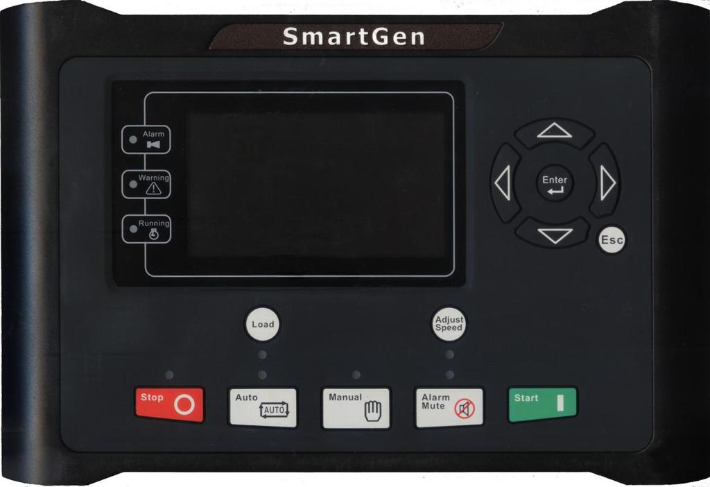
10 4 OPERATION 4.1 INDICATOR LIGHT Note: Selected indicators description: Warning indicator and Alarm indicator: Alarm Type Warning Indicator Alarm Indicator Warning Slow flashing Slow flashing Shutdown Alarm Off Fast flashing Running indicator: illuminated from crank successful to ETS while off during other periods. ISSUE Version 1.1 Page 10 of 68
11 4.2 PUSHBUTTONS Stop Start Manual Mode Auto Mode Mute Load Adjust Speed Stop running pump unit in Auto/Manual mode; Reset alarm in stop mode; Lamp test (press at least 3 seconds); During stopping process, press this button again to stop pump unit immediately. Start pump unit in Manual/Test mode. Press this key and controller enters in Manual mode. Press this key and controller enters in Auto mode. Alarming sound off; If there is alarm, pressing the button at least 3 seconds can reset this alarm. Can control the clutch to switch on or off in manual mode. Enter/Exit the speed adjust menu. Up/Increase Down/Decrease Left 1) Screen scroll; 2) Up cursor and increase value in setting menu. 1) Screen scroll; 2) Down cursor and decrease value in setting menu. 1) Screen scroll; 2) Left move cursor in setting menu. Right Set/Confirm Exit 1) Screen scroll; 2) Right move cursor in setting menu. 1. Enter into help interface; 2. Pressing and holding for more than 3 seconds enters parameter configuration menu; 3. In settings menu confirms the set value. 1. Returns to the main menu; 2. In settings menu returns to the previous menu. NOTE: In manual mode, pressing and simultaneously will force generator to crank. Successful start will not be judged according to crank disconnect conditions, operator will have to crank the starter motor manually; when operator decides that the engine has fired, he/she should release the button and start relay will be deactivated, safety on delay will start. WARNING: Default password is 00318, user can change it in case of others change the advanced parameters setting. Please clearly remember the password after changing. If you forget it, please contact Smartgen services and send all information in the controller page of ABOUT to us. ISSUE Version 1.1 Page 11 of 68
12 4.3 LCD DISPLAY MAIN DISPLAY Main screen is divided into left and right separate viewing areas, use to select a viewing area; the selected area is marked with in its upper left corner. Both viewing areas show pages; use to scroll the pages and to scroll the screen. Engine, including as below, Engine status, engine temperature, engine oil pressure, fuel level, Configurable Sensor 1, battery voltage, charger voltage, accumulated run time, accumulated start times. NOTE: If connected with J1939 engine via CANBUS port, this page also includes: coolant pressure, coolant level, fuel temperature, fuel pressure, inlet temperature, exhaust temperature, turbo pressure, fuel consumption, total fuel consumption and so on. (Different engine with different parameters) Pump Unit: Outlet pressure, pump flow, pump head, config. sensor 2~6 (can be set as temperature sensor, pressure sensor or level sensor) Formula:Pump Head = (Outlet pressure - Static Pressure)/ Pump flow is calculated according to relation curve of outlet pressure and flow; the relation curve should be set by users according to the actual usage. Alarm: Display all warnings, shutdown alarms, trip shutdown alarms and the corresponding information. NOTE: For ECU alarms and shutdown alarms, if the alarm information is displayed, check engine according to it, otherwise, please check the manual of generator according to SPN alarm code. Event log Records all start/stop events (shutdown alarm, trip shutdown alarm, manual/auto start or stop) and the real time when alarm occurs. Others, including, Time and Date, maintenance due time, input/output ports status. About, including, Issue time of software and hardware version, product PD number. Miscellaneous, including: ISSUE Version 1.1 Page 12 of 68
13 Working mode,engine status,engine temperature,engine oil pressure,fuel level, outlet pressure,config. sensor 2(inlet pressure), accumulated run time, real-time clock. Press in main screen can jump to miscellaneous screen Status, including as below, Engine speed, battery voltage 1, engine status Indicator Green Yellow Red Example: Engine On load Manual Mode Normal Running Status Normal status; No alarm Warning or idle speed alarm occurs. Shutdown alarm occurs. Pump Outlet Pressure 1.0MPa 10Bar 145psi Config Sensor Engine Temp Config Sensor 3 Oil Pressure 465kPa 4.65Bar 67.4psi 465kPa 4.65Bar 67.4psi Config Sensor 4 100% 1500rpm 27.6V Normal Running Engine Pump Fuel Level 100% Config Sensor Config Sensor Config Sensor Battery Voltage V Pump Flow 200m³/h Battery Voltage V Pump Head 102m 1500rpm 27.6V Emergency Stop ISSUE Version 1.1 Page 13 of 68
14 Press and hold Parameter USER MENU AND PARAMETERS SETTING MENU for more than 3 seconds to enter into user menu; After entering the correct password (factory default password is 00318), you can enter into parameter settings interface. Language Selectable Chinese, English and others (default: Espanol) Commissioning On load, off load or custom commissioning can be chosen. Custom commissioning can configure on load or not during commissioning, when to commissioning and select the mode after commissioning (manual mode, auto mode and stop mode). Clear users accumulation Can clear User Accumulated Run A, User Accumulated Run B, Engine Accumulated Run time and Accumulated Start times. Parameter setting including as following, Timer settings Engine settings Analog sensor settings (Engine temperature, engine oil pressure, fuel level, config. 1~6, outlet pressure) Input port settings output port settings GOV settings Pump settings Module settings Scheduling and maintenance settings Example, Return Timers > Engine Temp. Sensor OP Sensor Level Sensor Config Sensor 1 Config Sensor 2 Config Sensor 3 Config Sensor 4 Config Sensor 5 >Start Delay >Stop Delay >Preheat Delay >Cranking Time > Crank Rest Time > Safety On Time > Start Idle Time > Warming Up Time > Cooling Time > Stop Idle Time > ETS Hold Time Form1: Use to scroll settings, to enter settings (form2), exit settings menu. to ISSUE Version 1.1 Page 14 of 68
15 Return > Start Delay Form 2: Use to scroll Timers > >Stop Delay Engine >Preheat Delay settings (form 3), to enter settings Temp. Sensor >Cranking Time OP Sensor >Crank Rest Time (form 4), to return to previous Level Sensor >Safety On Time menu. (form 1). Config Sensor 1 >Start Idle Time Config Sensor 2 >Warming Up Time Config Sensor 3 >Cooling Time Config Sensor 4 >Stop Idle Time Config Sensor 5 > ETS Hold Time Return Timers > Engine Temp. Sensor OP Sensor Level Sensor Config Sensor 1 Config Sensor 2 Config Sensor 3 Config Sensor 4 Config Sensor 5 >Start Delay >Stop Delay >Preheat Delay >Cranking Time >Crank Rest Time >Safety On Time >Start Idle Time >Warming Up Time >Cooling Time >Stop Idle Time >ETS Hold Time Form 3: Use to scroll settings, to enter settings (form4), to return to previous menu. (form 1). > Start Delay > Stop Delay > Preheat Delay >Cranking Time >Crank Rest Time > Safety On Time > Start Idle Time > Warming Up Time > Cooling Time > Stop Idle Time > ETS Hold Time Form 4:Press to enter settings (form 5), to return to previous menu. (form 6). ISSUE Version 1.1 Page 15 of 68
16 > Start Delay > Stop Delay > Preheat Delay >Cranking Time >Crank Rest Time > Safety On Time > Start Idle Time > Warming Up Time > Cooling Time > Stop Idle Time > ETS Hold Time Form5: Press to change cursor position, are used for changing cursor value, Confirm setting (form 4), exit setting (form 4). > Start Delay > Stop Delay > Preheat Delay > Cranking Time > Crank Rest Time > Safety On Time > Start Idle Time > Warming Up Time > Cooling Time > Stop Idle Time > ETS Hold Time > Wait Stop Time Form 6: are used for changing the setting contents. Confirm setting (form 4), to return to previous menu. (form 1). NOTE: Pressing can exit setting directly during setting. ISSUE Version 1.1 Page 16 of 68
17 4.4 AUTO START/STOP OPERATION Auto mode is selected by pressing the button; a LED besides the button will illuminate to confirm the operation. Automatic Start Sequence: 1. When Remote Start is active, Start Delay timer is initiated; 2. When start delay is over, preheat relay energizes (if configured), preheat delay XX s information will be displayed on LCD; 3. After the above delay, the Fuel Relay is energized, and then one second later, the Start Relay is engaged. The engine is cranked for a pre-set time. If the pump unit fails to fire during this cranking attempt then the fuel relay and start relay are disengaged for the pre-set rest period; crank rest time begins and wait for the next crank attempt. 4. Should this start sequence continue beyond the set number of attempts, the start sequence will be terminated, the Fail to Start fault will be displayed on LCD. 5. In case of successful crank attempt, the Safety On timer is activated, allowing Low Oil Pressure, High Temperature, Under speed and Charge Alternator Failure inputs to stabilize without triggering the fault. As soon as this delay is over, start idle delay is initiated (if configured). 6. During start idle delay, under speed alarm is inhibited. When this delay is over, warming up delay is initiated (if configured). 7. After the warming up delay, If engine speed has reached on-load requirements, then the pump close relay will be energized; pump uint will take load; pump unit will enter into Normal Running status. NOTE: In case of Remote Start (off Load), the procedure is the same, except for step NO. 7: the pump close relay will NOT be energised, generator will NOT accept load. Automatic Stop Sequence, 1) When the Remote Start signal is deactivated while the Remote Stop signal is active, the Stop Delay is initiated. 2) Once this stop delay has expired, the Pump Unit Breaker will open and the Cooling Delay is then initiated. Should the Remote Start signal be re-activated during the cooling down period, the unit will return running status. Once the Cooling Delay expires, the Stop Idle delay is initiated. 3) During Stop Idle Delay (if configured), idle relay is energized. ISSUE Version 1.1 Page 17 of 68
18 4) ETS Solenoid Hold begins, ETS relay is energized while fuel relay is de-energized and complete stop is detected automatically 5) "Fail to Stop Delay" begins, complete stop is detected automatically. 6) Pump unit is placed into its After stop time after its complete stop. Otherwise, fail to stop alarm is initiated and the corresponding alarm information is displayed on LCD (If pump unit stopped successfully after Failed to Stop alarm, it will enter After stop time and remove alarm). 7) Pump unit is placed into its standby mode after its After stop time. ISSUE Version 1.1 Page 18 of 68
19 4.5 MANUAL START/STOP OPERATION 1 Manual Start: Manual mode is selected by pressing the button; a LED besides the button will illuminate to confirm the operation; then press button to start the unit; can automatically detect crank successful, and unit accelerates to high-speed running automatically. When After Unload Idle is enabled, the unit is idle running when crank succeed; unit accelerates to high-speed running automatically and take load after press key by manual. With high temperature, low oil pressure and over speed during pump unit running, controller can protect it to stop quickly (please refer to No.2~7 of Auto start operation for detail procedures). 2 MANUAL STOP: Press can stop the running pump unit. (please refer to No.2~7 of Auto stop operation for detail procedures). NOTE: In manual mode, users can control the pump unit on load or off load via Load key. ISSUE Version 1.1 Page 19 of 68
20 4.6 ON-LOAD CONTROL PROCESS When controller is in Manual mode, manual control will be executed. Users can control the pump unit on load or off load by pressing key. The pump unit will unload automatically when it is stopped. If After Unload Idle is selected Disable Start the pump unit in manual mode and press key during the genset is normal running, then the engine will take load; press key again, the engine will unload and the generator is normal running. If After Unload Idle is selected Enable : Start the pump unit in manual mode and it enters into idle running process. The pump unit will not enter into normal running status until key is pressed and it will take load as soon as the on-load requirements have reached. When the pump unit is normal running with load, press key once again will lead to the unit s offload (i.e. load relay deactivated); then the cooling delay will be initiated. Once this has expired, the unit will enter into idle running status. When controller is in Auto mode, auto control will be executed. The pump unit will take load automatically when it is normal running and the on-load requirements have reached while unload automatically when it is stopped. ISSUE Version 1.1 Page 20 of 68
21 4.7 ADJUST SPEED CONTROL Users can set the outlet pressure as the rated value simply by adjusting the engine speed. The Adjust Speed Control was divided into auto control and manual control. Manual Adjust Speed: Adjust Speed mode is selected by pressing the button; In this interface, users can adjust speed using navigational button:, manual adjust speed;, auto adjust speed;, manual raise speed;, manual drop speed., manual raise speed and, manual drop speed buttons are active only when pump unit is normal running under Manual Adjust Speed mode. Auto Adjust Speed: Under this mode, during the unit is normal running, the controller will adjust the outlet pressure/inlet pressure according to the preset to rated speed and maintain its steady automatically. The Auto Adjust Speed was divided into relay adjust speed, GOV adjust speed and CAN adjust speed. Relay Adjust Speed: Control the engine servo motor simply by using speed raise relay and speed drop relay. GOV Adjust Speed: Control the electronic speed regulator simply by using GOV analog signal. Users should set parameters according to the actual situation as different regulators have different parameters. CAN Adjust Speed: Control the ECU engine speed simply by using CAN interface. Parameters setting and speed adjustment method are same as GOV. SW1 should set as 5.0 and SW2 as 2.0 while adjusting. ISSUE Version 1.1 Page 21 of 68
22 5 PROTECTION 5.1 WARNINGS Warnings are not shutdown alarms and do not affect the operation of the genset. Warning does not lead to shutdown, and when warning condition is no longer present, warning alarm will be cleared automatically. Warning types are as follows: No. Type Description 1 Over Speed When the controller detects that the engine speed has exceeded the pre-set value, it will initiate a warning alarm. 2 Under Speed When the controller detects that the engine speed has fallen below the pre-set value, it will initiate a warning alarm. 3 When the controller detects that the engine speed is 0 Loss of Speed and the action select Warn, it will initiate a warning Signal alarm. 4 Fail To Stop After fail to stop delay, if unit is not stop completely, it will initiate a warning alarm. 5 Charge Alt Fail When the controller detects that charger voltage has fallen below the pre-set value, it will initiate a warning alarm. 6 7 Battery 1 Over Voltage Battery 1 Under Voltage 8 Maintenance Due 9 ECU Warn 10 Temperature Sensor Circuit Open 11 High Temperature 12 Low Temperature 13 Oil Pressure Open Circuit When the controller detects that battery 1 voltage has exceeded the pre-set value, it will initiate a warning alarm. When the controller detects that battery 1 voltage has fallen below the pre-set value, it will initiate a warning alarm. When maintenance countdown time is 0 and the action select Warn, it will initiate a warning alarm. If an error message is received from ECU via J1939, it will initiate a warning alarm. When the controller detects that the temperature sensor is open circuit and the action select Warn, it will initiate a warning alarm. When the controller detects that engine temperature has exceeded the pre-set value, it will initiate a warning alarm. When the controller detects that engine temperature has fallen below the pre-set value, it will initiate a warning alarm. When the controller detects that the oil pressure sensor is open circuit and the action select Warn, it will ISSUE Version 1.1 Page 22 of 68
23 No. Type Description initiate a warning alarm. 14 Low Oil Pressure When the controller detects that the oil pressure has fallen below the pre-set value, it will initiate a warning alarm. 15 Level Sensor Open When the controller detects that the level sensor is open circuit and the action select Warn, it will initiate a warning alarm. 16 Low Fuel Level When the controller detects that the fuel level has fallen below the pre-set value, it will initiate a warning alarm. 17 When the controller detects that the sensor is open Flexible Sensor circuit and the action select Warn, it will initiate a 1~6 Open warning alarm. 18 Flexible Sensor When the controller detects the sensor value is higher 1~6 High than the max. set value, it will initiate a warning alarm. 19 Flexible Sensor When the controller detects the sensor value is lower 1~6 Low than the min. set value, it will initiate a warning alarm. 20 Digital Input 1~9 When the action of digital input port select Warn and Warn active, it will initiate a warning alarm. 21 When the controller detects that battery 2 voltage has Battery 2 Over exceeded the pre-set value, it will initiate a warning Voltage alarm Battery 2 Under Voltage Outlet Pressure Sensor Open Outlet Pressure Sensor High Outlet Pressure Sensor Low 26 Over Flow Warn Gearbox speed Gearbox speed Over Under End Of The Mandate When the controller detects that battery 2 voltage has fallen below the pre-set value, it will initiate a warning alarm. When the controller detects that the outlet pressure sensor is open circuit and the action select Warn, it will initiate a warning alarm. When the controller detects the sensor value is higher than the max. set value, it will initiate a warning alarm. When the controller detects the sensor value is lower than the min. set value, it will initiate a warning alarm. When the controller detects the flow value is higher than the max. set value, it will initiate a warning alarm. When the controller detects that the gearbox speed has exceeded the pre-set value, it will initiate a warning alarm. When the controller detects that the gearbox speed has fallen below the pre-set value, it will initiate a warning alarm. When the mandate time has expired and the action select Warn, it will initiate a warning alarm. ISSUE Version 1.1 Page 23 of 68
24 5.2 SHUTDOWN ALARM When controller detects shutdown alarm, it will send signal to open breaker and stop the unit. Shutdown alarm must be cleared manually and the fault removed to reset the module. Shutdown alarm types are as follows: NO. Type Description 1 Emergency Stop 2 Over Speed 3 Under Speed 4 Loss of Speed Signal 5 Maintenance Due 6 ECU Shutdown 7 ECU Fail 8 Temperature Sensor Circuit Open 9 High Temperature 10 Oil Pressure Open Circuit 11 Low Oil Pressure Level Sensor Open Circuit Flexible 1~6 Open Sensor When the controller detects an emergency stop alarm signal, it will initiate a shutdown alarm. When the controller detects that the generator speed has exceeded the pre-set value, it will initiate a shutdown alarm. When the controller detects that the generator speed has fallen below the pre-set value, it will initiate a shutdown alarm. When the controller detects that the engine speed is 0 and the action select Warn, it will initiate a shutdown alarm. When maintenance countdown time is 0 and the action select Shutdown, it will initiate a shutdown alarm. If shutdown alarm signal is received from ECU via J1939, it will initiate a shutdown alarm. If the module does not detect the J1939 data, it will initiate a shutdown alarm. When the controller detects that the temperature sensor is open circuit and the action select Shutdown, it will initiate a shutdown alarm. When the controller detects that engine temperature has exceeded the pre-set value, it will initiate a shutdown alarm. When the controller detects that the oil pressure sensor is open circuit and the action select Shutdown, it will initiate a shutdown alarm. When the controller detects that the oil pressure has fallen below the pre-set value, it will initiate a shutdown alarm. When the controller detects that the sensor is open circuit and the action select Shutdown, it will initiate a shutdown alarm. When the controller detects that the sensor is open circuit and the action select Shutdown, it will initiate a shutdown alarm. ISSUE Version 1.1 Page 24 of 68
25 NO. Type Description When the controller detects the sensor value is higher Flexible Sensor 16 than the max. set value, it will initiate a shutdown 1~6 High alarm Flexible 1~6 Low Sensor Digital Input 1~9 Shutdown Outlet Pressure Sensor Open Outlet Pressure Sensor High Outlet Pressure Sensor Low Over Shutdown Gearbox speed Gearbox speed Flow Over Under End Of The Mandate When the controller detects the sensor value is lower than the min. set value, it will initiate a shutdown alarm. When the action of digital input port select Shutdown and active, it will initiate a shutdown alarm. When the controller detects that the outlet pressure sensor is open circuit and the action select Shutdown, it will initiate a shutdown alarm. When the controller detects the sensor value is higher than the max. set value, it will initiate a shutdown alarm. When the controller detects the sensor value is lower than the min. set value, it will initiate a shutdown alarm. When the controller detects the flow value is higher than the max. set value, it will initiate a shutdown alarm. When the controller detects that the gearbox speed has exceeded the pre-set value, it will initiate a shutdown alarm. When the controller detects that the gearbox speed has fallen below the pre-set value, it will initiate a shutdown alarm. When the mandate time has expired and the action select Shutdown, it will initiate a shutdown alarm. ISSUE Version 1.1 Page 25 of 68
26 5.3 TRIP SHUTDOWN On initiation of the trip shutdown condition the controller will de-energize the load output to remove the load from the unit. Once this has occurred, the controller will start the Cooling delay and allow the engine to cool before shutting down the engine. Trip shutdown alarm must be cleared manually and the fault removed to reset the module. Trip shutdown alarm types are as follows: NO. Types Description 1 Maintenance Due When maintenance countdown time is 0 and the action select Trip Shutdown, it will initiate a trip shutdown alarm. 2 Digital Input 1~9 When the action of digital input port select Trip Shutdown and active, it will initiate a trip shutdown alarm. ISSUE Version 1.1 Page 26 of 68
27 5.4 FAULT IDLE On initiation of the trip condition the controller will de-energize the load output to remove the load from the unit. Once this has occurred the controller will start the Cooling delay and allow the engine to cool before idle running process. Fault idle alarm must be cleared by pressing Mute button more than 3s manually. Fault idle alarm types are as follows: No. Types Description 1 Digital Input 1~9 When the action of digital input port select Fault idle and active, it will initiate a trip shutdown alarm. ISSUE Version 1.1 Page 27 of 68
28 5.5 INDICATION On initiation of the indication alarm the controller does not perform any action, and the alarm information will be displayed on Alarm page. Indication alarm types are as follows: No. Types Description 1 Maintenance Due When maintenance countdown time is 0 and the action select Indication, it will initiate a indication alarm. 2 Digital Input 1~9 When the action of digital input port select Indication and active, it will initiate a indication alarm. ISSUE Version 1.1 Page 28 of 68

29 6 CONNECTIONS APC715 controller back panel is shown below: Description of terminal connections: Cable Pin Function Description Size 1 B- 2.5mm 2 Connected with negative of starter battery. 2 B+ 2.5mm 2 wire length is over 30m, better to double wires Connected with positive of starter battery. If in parallel. Max. 20A fuse is recommended. 3 Emergency Stop 2.5mm 2 Connected with B+ power supply via emergency stop button. 4 Fuel Relay Output 1.5mm 2 B+ power is supplied by terminal 3, rated 16A 5 Start Relay Output 1.5mm 2 B+ power is supplied by terminal 3, rated 16A 6 Aux. Output 1 1.5mm 2 B+ power is supplied by terminal 2, rated 7A 7 Aux. Output 2 1.5mm 2 B+ power is supplied by terminal 2, rated 7A 8 Aux. Output 3 1.5mm 2 B+ power is supplied by terminal 2, rated 7A 9 Aux. Output 4 1.5mm 2 B+ power is supplied by terminal 2, rated 7A Connected to starter coil Details see form 2 ISSUE Version 1.1 Page 29 of 68
30 Pin Function Cable Size Description 10 Aux. Output 5 1.5mm 2 B+ power is supplied by terminal 2, rated 7A 11 Aux. Output 6 1.5mm 2 B+ power is supplied by terminal 2, rated 7A 12 Charger(D+) 1.0mm 2 terminals. Being hang up If there is no this Connected with charger starter s D+ (WL) terminal. 13 Aux. Input 1 1.0mm 2 Ground connected is active (B-) 14 Aux. Input 2 1.0mm 2 Ground connected is active (B-) 15 Aux. Input 3 1.0mm 2 Ground connected is active (B-) 16 Aux. Input 4 1.0mm 2 Ground connected is active (B-) 17 Aux. Input 5 1.0mm 2 Ground connected is active (B-) 18 Aux. Input 6 1.0mm 2 Ground connected is active (B-) 19 Aux. Input 7 1.0mm 2 Ground connected is active (B-) 20 Aux. Input 8 1.0mm 2 Ground connected is active (B-) 21 Aux. Input 9 1.0mm 2 Ground connected is active (B-) 22 Common GND(B-) 1.0mm 2 (B-) has already connected innerly. Details see form 3 Gearbox Magnetic Connected with Gearbox Speed Sensor, 23 Pickup 1 0.5mm 2 shielding (B-) has Gearbox Magnetic already connected with speed sensor 2 24 Pickup 2 innerly. 25 Magnetic Pickup (B-) has already connected with ground GND innerly. Engine Connected with Engine Speed Sensor, 26 Magnetic Pickup 2 0.5mm 2 shielding (B-) has Engine already connected with speed sensor 2 27 Magnetic Pickup 1 innerly. 28 Battery 2 Volt 1.0mm 2 Connected with positive of battery Normally close output, rated 7A 30 Aux. Output 7 1.5mm 2 Public points of relay 31 Normally open output, rated 7A 32 Normally close output, rated 7A 33 Aux. Output 8 1.5mm 2 Public points of relay 34 Normally open output, rated 7A Details see 35 Normally close output, rated 7A form 2 36 Aux. Output 9 1.5mm 2 Public points of relay 37 Normally open output, rated 7A 38 Normally close output, rated 7A 39 Aux. Output mm 2 Public points of relay 40 Normally open output, rated 7A ISSUE Version 1.1 Page 30 of 68
31 Pin Function Cable Size Description 41 GOV B2+ 0.5mm 2 120kΩ resistance had been connected to GOV B+ innerly. 42 GOV B1+ 0.5mm 2 2-core shielding wire is recommended, its 43 GOV A- 0.5mm 2 GOV end earthed. 44 ECU CAN L 0.5mm 2 Impedance-120Ω shielding wire is 45 ECU CAN H 0.5mm 2 recommended, its single-end earthed. 120Ω 46 ECU CAN COM / matched resistance has already connected internally. 47 NC Not connect. 48 Outlet Pressure Sensor 1.0mm 2 Connect to outlet pressure sensor 49 Aux. sensor 6 1.0mm 2 50 Aux. sensor 5 1.0mm 2 Spare sensor of pump unit 51 Sensor COM 3 1.0mm 2 Public terminal of sensor, (B-) has already connected. 53 Aux. sensor 3 1.0mm 2 Spare sensor of pump unit 52 Aux. sensor 4 1.0mm 2 54 Aux. sensor 2 1.0mm 2 Details see form 4 55 Sensor COM 2 1.0mm 2 Public terminal of sensor, (B-) has already connected. 56 Aux. sensor 1 1.0mm 2 Spare sensor of engine 57 Oil pressure sensor 1.0mm 2 Connected to oil pressure sensor 58 Temperature sensor 1.0mm 2 Connected to temperature sensor 59 Fuel level sensor 1.0mm 2 Connected to fuel level sensor 60 Sensor COM 1 1.0mm 2 Public terminal of sensor, (B-) has already connected. 61 RS485 / 62 RS mm 2 63 RS mm 2 Impedance-120Ω shielding wire is recommended, its single-end earthed. NOTE: USB ports in controller rear panel are programmable parameter ports, user can directly configure controller via PC in stop mode. ISSUE Version 1.1 Page 31 of 68
32 7 DEFINITION AND RANGE OF PARAMETERS 7.1 PARAMETER CONTENTS AND RANGE (TABLE 1) No. Items Parameter Default Description Timer Setting 1 Start Delay (0-3600)s 1 Time from remote start signal is active to start the pump unit. 2 Stop Delay (0-3600)s 1 Time from remote stop signal is deactivated to stop the pump unit. 3 Preheat Time of pre-powering heat plug (0-3600)s 0 Delay before starter is powered up. 4 Cranking Time (3-60)s 8 Time of starter power up 5 Crank Rest The waiting time before second (3-60)s 10 Time power up when engine start fail. Alarms for low oil pressure, high 6 Safety On temperature, under speed, under (0-3600)s 10 Delay frequency/voltage, charge fail are inactive. 7 Start Idle Idle running time of the pump unit (0-3600)s 0 Time when starting. 8 Warming time between the pump Warming Up (0-3600)s 10 unit take load and high speed Time running. 9 Cooling Radiating time before stop the pump (0-3600)s 10 Time unit, after it unloads. 10 Stop Idle Idle running time when pump unit (0-3600)s 0 Time stop ETS Solenoid Hold Fail to Stop Delay After Stop 13 Time Engine Setting (0-3600)s 20 (0-3600)s 0 (0-3600)s 0 1 Engine Type (0-39) 0 Stop electromagnet s power on time when pump unit is stopping. Time between ending of pump unit idle delay and stopped when ETS time is set as 0; Time between ending of ETS hold delay and stopped when ETS Hold output time is not 0. Time between pump unit stopped and standby. Default: Conventional genset (not J1939) When connected to J1939 engine, ISSUE Version 1.1 Page 32 of 68
33 No. Items Parameter Default Description choose the corresponding type. Tooth number of the engine, for 2 judging of starter separation Flywheel (10-300) 118 conditions and inspecting of engine Teeth speed. See the following Installation Instruction. 3 Rated Speed (0-6000)RPM 1500 Offer standard to judge over/under/loading speed. Setting value is percentage of rated 4 speed. Controller detects when it is Speed on (0-1000)% 90% ready to load. It won t enter into Load normal running process when speed is lower than loading speed. 5 Loss of Time from detecting speed is 0 to Speed (0-3600)s 5 confirm the action. Signal Loss of 6 Speed Action (0-1) 0 0:Warn; 1:Shutdown Over Speed 7 (0-1000)% 114% Shutdown Setting value is percentage of rated Under speed and delay value can be set. 8 Speed (0-1000)% 80% Shutdown Over Speed 9 (0-1000)% 110% Setting value is percentage of rated Warn speed. Delay value and return value Under 10 (0-1000)% 86% can be set. Speed Warn 11 Battery 1 Standard for detecting over/under Rated (0-60.0)V 24.0 voltage of battery. Voltage Battery 1 12 (0-1000)% 120% Setting value is percentage of rated Over Volts voltage of battery. Delay value & Battery 1 13 (0-1000)% 85% return value can be set. Under Volts 14 Battery 2 Standard for detecting over/under Rated (0-60.0)V 24.0 voltage of battery. Voltage Battery 2 15 (0-1000)% 120% Setting value is percentage of rated Over Volts voltage of battery. Delay value & Battery 2 16 (0-1000)% 85% return value can be set. Under Volts 17 Charge Alt (0-60.0)V 8.0 In normal running, when charger ISSUE Version 1.1 Page 33 of 68
34 No. Items Parameter Default Description Fail D+(WL) voltage under this value, charge failure alarms. 18 Max. Crank times of crank attempts. Start (1-10) times 3 When reach this number, controller Attempts will send start failure signal Crank Disconnect Disconnect Engine Speed Disconnect Oil Pressure After Unload Idle Engine Set Idle (0-2) 2 (0-1000)% 24% (0-1000)kPa 200 (0-1) 0 (0-100)% 60 See form 5. There are 3 conditions of disconnecting starter with engine. Each condition can be used alone and simultaneously to separating the start motor and genset as soon as possible. Setting value is percentage of rated speed. When engine speed is higher than the set value, starter will be disconnected. See the following Installation Instruction. When generator oil pressure is higher than the set value, starter will be disconnected. See the following Installation Instruction. 0: Disable;1: Enable Active when system is in manual mode. After start the unit, it is enter into idle running when the unit is not on-load. Setting value is percentage of rated speed. Stabilize the engine speed on the set value if idle running is needed. Module Setting 1 Power on 0: Stop mode 1: Manual mode 2: (0-2) 0 Mode Auto mode 2 Module Controller s address during remote (1-254) 1 Address sensing. 3 Stop Bits (0-1) 0 0: 2 stop bits; 1: 1 stop bit 4 Language (0-2) 0 0: Simplified Chinese 1: English 2: Others 5 Password ( ) For entering advanced parameters setting. 6 Time and Date User set Scheduling And Maintenance Setting 1 Scheduled (0-1) 0 0: Disable;1: Enable ISSUE Version 1.1 Page 34 of 68
35 No. Items Parameter Default Description Run 2 Scheduled Not Run (0-1) 0 0: Disable;1: Enable Maintenance 3 (0-1) 0 1 0: Disable;1: Enable Maintenance 4 (0-1) 0 Users can set maintenance time, 2 maintenance due action, prealarm A, Maintenance 5 (0-1) 0 prealarm B, timer mode and reset 3 maintenance alarm. If maintenance Maintenance 6 (0-1) 0 due alarm occurs, users can reset 4 maintenance alarm to remove it. Maintenance 7 (0-1) 0 5 Analog Sensors Setting Temperature Sensor 1 Curve Type (0-15) 7 SGX. See form 5. 2 Open Circuit Action (0-2) 0 0: Warn; 1: Shutdown; 2: No action Shutdown when external sensor 3 temperature is higher than this High Temp. (0~300)ºC 98 value. Detecting only after safety Shutdown delay is over. The delay value can be set. Warn when external sensor 4 temperature is higher than this High Temp. (0~300)ºC 95 value. Detecting only after safety Warn delay is over. The delay value and return value can be set. 5 Low Temp. Warn (0-1) 0 0: Disable;1: Enable 6 Users should set the corresponding Custom curve when select resistor curve Curve type or current curve type. Oil Pressure Sensor 1 Curve Type (0-15) 7 SGX. See form 5. 2 Open Circuit Action (0-2) 0 0: Warn; 1: Shutdown; 2: No action Shutdown when external oil 3 Low OP pressure is lower than this value. (0-1000)kPa 103 Shutdown Detecting only after safety delay is over. The delay value can be set. 4 Low OP Warn when external oil pressure is (0-1000)kPa 124 Warn higher than this value. Detecting ISSUE Version 1.1 Page 35 of 68
36 No. Items Parameter Default Description only after safety delay is over. The delay value and return value can be set. 5 Custom Curve Users should set the corresponding curve when select resistor curve type or current curve type. Liquid Level Sensor 1 Curve Type (0-15) 4 SGH. See form 5. 2 Open Circuit Action (0-2) 0 0:Warn; 1:Shutdown; 2:No action Warn when external level is lower 3 Low Level than this value. It is detecting all the (0-1000)% 10 Warn time. The delay value and return value can be set. 4 Users should set the corresponding Custom curve when select resistor curve Curve type or current curve type. Flexible Sensor 1~6 1 Flexible Sensor Setting (0-1) 0 0: Disable;1: Enable (can be set as temperature/oil pressure/liquid lever sensor) 2 Curve Type Depends on sensor type. 3 Open Circuit Action (0-2) 0 0:Warn; 1:Shutdown; 2:No action Shutdown when external sensor 4 High value is higher than this value. The (0-9000) 100 Shutdown delay value and warn enable can be set. 5 Low Shutdown (0-9000) 10 6 High Warn (0-9000) 90 7 Low Warn (0-9000) 20 8 Custom Curve Shutdown when external sensor value is lower than this value. The delay value and warn enable can be set. Warn when external sensor value is higher than this value. The delay value, warn enable and return value can be set. Warn when external sensor value is lower than this value. The delay value, warn enable and return value can be set. Users should set the corresponding curve when select resistor curve type or current curve type. ISSUE Version 1.1 Page 36 of 68
37 No. Items Parameter Default Description Outlet Pressure Sensor 1 Curve Type (0-15) 2 2 Open Circuit Action (0-2) 1 0:Warn; 1:Shutdown; 2:No action 3 4 High Shutdown Low Shutdown (0-9000)% 120 (0-9000)% 10 5 High Warn (0-9000)% Low Warn (0-9000)% 20 7 Custom Curve Shutdown when external sensor value is higher than this value. The delay value and warn enable can be set. Shutdown when external sensor value is lower than this value. The delay value and warn enable can be set. Warn when external sensor value is higher than this value. The delay value, warn enable and return value can be set. Warn when external sensor value is lower than this value. The delay value, warn enable and return value can be set. Users should set the corresponding curve when select resistor curve type or current curve type. Set the outlet port s rated working pressure of pump unit. Set the outlet port s static pressure of pump unit. 8 Rated Outlet Pressure (0-9000)kPa Static Pressure (0-9000)kPa 0 10 Flow Function (0-1) 0 0: Disable;1: Enable 11 Rated Flow ( )m³/h 1000 Pump unit s rated working pressure. During normal running process, it 12 will initiated a warning alarm signal Over Flow (0-1000)% 110 when flow value has exceed the set Warn value. The delay value, warn enable and return value can be set. 13 Over Shut Flow 14 Flow Curve Flexible Input Ports (0-1000)% 120 During normal running process, it will initiate a shutdown alarm signal when flow value has exceeded the set value. The warn enable and delay value can be set. Different outlet pressures correspond to different flow value. ISSUE Version 1.1 Page 37 of 68
38 No. Items Parameter Default Description Flexible Input Port 1 1 Contents Setting (0-53) 28 Remote start (on load). See form 3. 2 Active Type (0-1) 0 0: Closed to active 1: Open to active Flexible Input Port 2 1 Contents High temperature shutdown. (0-53) 26 Setting See form 3. 2 Active Type (0-1) 0 0: Closed to active 1: Open to active Flexible Input Port 3 1 Contents Low oil pressure shutdown. (0-53) 27 Setting See form 3. 2 Active Type (0-1) 0 0: Closed to active 1: Open to active Flexible Input Port 4 1 Contents User defined. (0-53) 0 Setting See form 3. 2 Active Type (0-1) 0 0: Closed to active 1: Open to active 3 Arming (0-3) 2 0: From safety on 1: From starting 2: Always 3:Never 4 Active 0: Warn; 1: Shutdown; 2: Trip (0-4) 0 Actions Shutdown 3: Fault Idle 4: Indication 5 Active Delay (0-20.0)s 2.0 Time from detecting active to confirm. 6 Description User defined. Flexible Input Port 5 1 Contents User defined. (0-53) 0 Setting See form 3. 2 Active Type (0-1) 0 0: Closed to active 1: Open to active 3 Arming (0-3) 2 0: From safety on 1: From starting 2: Always 3:Never 4 Active 0: Warn; 1: Shutdown; 2: Trip (0-4) 0 Actions Shutdown 3: Fault Idle 4: Indication 5 Active Delay (0-20.0)s 2.0 Time from detecting active to confirm. 6 Description User defined. Flexible Input Port 6 1 Contents Setting (0-53) 0 User defined. See form 3. ISSUE Version 1.1 Page 38 of 68
39 No. Items Parameter Default Description 2 Active Type (0-1) 0 0: Closed to active 1: Open to active 3 Arming (0-3) 2 0: From safety on 1: From starting 2: Always 3:Never 4 Active 0: Warn; 1: Shutdown; 2: Trip (0-4) 1 Actions Shutdown 3: Fault Idle 4: Indication 5 Active Delay (0-20.0)s 2.0 Time from detecting active to confirm. 6 Description User defined. Flexible Input Port 7 1 Contents Setting (0-53) 5 Lamp Test. See form 3. 2 Active Type (0-1) 0 0: Closed to active 1: Open to active Flexible Input Port 8~9 1 Contents Setting (0-53) 0 User defined. See form 3. 2 Active Type (0-1) 0 0: Closed to active 1: Open to active 3 Arming (0-3) 0 0: From safety on 1: From starting 2: Always 3:Never 4 Active 0: Warn; 1: Shutdown; 2: Trip (0-4) 0 Actions Shutdown 3: Fault Idle 4: Indication 5 Active Delay (0-20.0)s 2.0 Time from detecting active to confirm. 6 Description User defined. Flexible Output Ports Flexible Output Port 1 1 Contents User defined period output (default (0-239) 1 Setting output is in preheating) See form 4. 2 Active Type (0-1) 0 0:Normally open; 1:Normally close Flexible Output Port 2 1 Contents Setting (0-239) 35 Idle speed control. See form 4. 2 Active Type (0-1) 0 0:Normally open; 1:Normally close Flexible Output Port 3 1 Contents Setting (0-239) 29 On-load control. See form 4. 2 Active Type (0-1) 0 0:Normally open; 1:Normally close Flexible Output Port 4 1 Contents (0-239) 31 Reserved. See form 4. ISSUE Version 1.1 Page 39 of 68
40 No. Items Parameter Default Description Setting 2 Active Type (0-1) 0 0:Normally open; 1:Normally close Flexible Output Port 5 1 Contents Setting (0-239) 38 ETS solenoid hold. See form 4. 2 Active Type (0-1) 0 0:Normally open; 1:Normally close Flexible Output Port 6 1 Contents Setting (0-239) 48 Common alarm. See form 4. 2 Active Type (0-1) 0 0:Normally open; 1:Normally close Flexible Output Port 7~10 1 Contents Setting (0-239) 0 Not used. See form 4. 2 Active Type (0-1) 0 0:Normally open; 1:Normally close GOV Setting 1 Adjust 0:Not Used; 1:Relay Adjust Speed; (0-2) 2 Speed Type 2:GOV Adjust Speed 2 GOV Output Reverse (0-1) 0 0:Disable;1:Enable. 3 GOV Center Voltage SW1 (0-10.0) 0 Default central voltage: 0V 4 GOV Voltage Range SW2 (0-10.0) 2.0 Default volt. range: (-2.5~+2.5)V 5 GOV Gain (0-100) 20 GOV gain control 6 GOV Stability (0-100) 20 GOV stability control 7 Relay Adjust Speed Dead Band (0-10.0)% GOV Relay (0-100)% 10 Gain GOV relay control 9 GOV Relay Stability ( )s GOV Relay Response ( ) Adjust Speed Object Inlet Pressure Stability (0-1) 0 (0-2000)kPa 10 0: Outlet Pressure,1:Inlet Pressure Configurable sensor 2 is regarded as inlet pressure sensor if the object is set as Inlet Pressure. Stabilize the inlet pressure on the set value if the object is set as Inlet Pressure. ISSUE Version 1.1 Page 40 of 68
41 No. Items Parameter Default Description Pump Unit Setting 1 Speed Enabled (0-1) 0 0:Disable;1:Enable. 2 Flywheel Teeth (1-300) 118 Tooth number of the engine. 3 Rated Speed (0-6000)RPM 500 Offer standard to judge over/under speed. 4 Over Speed (0-1000)% 114% Shut Setting value is percentage of rated 5 Under speed and delay value can be set. (0-1000)% 80% Speed Shut Over Speed 6 (0-1000)% 110% Setting value is percentage of rated Warn speed. Delay value and return value Under 7 (0-1000)% 86% can be set. Speed Warn ISSUE Version 1.1 Page 41 of 68
42 7.2 PROGRAMMABLE OUTPUT 1-5 (TABLE 2) No. Type Description 0 Not Used 1 Custom Period 1 2 Custom Period 2 3 Custom Period 3 4 Custom Period 4 5 Custom Period 5 6 Custom Period 6 7 Custom Combined 1 8 Custom Combined 2 9 Custom Combined 3 10 Custom Combined 4 11 Custom Combined 5 12 Custom Combined 6 13 Reserved 14 Reserved 15 Reserved 16 Start Relay B 17 Air Flap 18 Audible Alarm 19 Louver Control 20 Fuel Pump Control Details of function description please see the following. If Start Relay B is configured, start relay and start relay B will output alternately in multi-startup process; Are used to control double power supply ATS. Action when over speed shutdown and emergence stop. It can close the air inflow to stop the engine as soon as possible. Action when warning or shutdown occurs. Can be connected annunciator externally. When alarm mute input port is active, the alarm will be prohibit. Action in genset starting and disconnect when genset stopped completely. It is controlled by fuel pump of level sensor s limited threshold. 21 Heater Control It is controlled by heating of temperature sensor s limited threshold. 22 Cooler Control It is controlled by cooler of temperature sensor s limited threshold. 23 Oil Pre-supply Actions in period of cranking to safety run. 24 Reserved 25 Pre-Lubricate Actions in period of pre-heating to safety ISSUE Version 1.1 Page 42 of 68
43 26 Remote PC Output 27 Reserved 28 Reserved 29 On-load Output 30 Reserved 31 Reserved 32 Reserved 33 Crank Relay 34 Fuel Relay 35 Idle Control 36 Raise Speed 37 Drop Speed 38 ETS Control 39 Pulse Drop speed 40 ECU Stop 41 ECU Power Supply 42 Pulse raise speed 43 Crank Success run. This port is controlled by RS485 communication (PC). Control generator to take load or off load. Action when genset is starting and disconnect when crank successful. Action when genset is starting and disconnect when stop is completed. Used for engine which has idles. Close before starting and open in warming up delay; Close during stopping idle process and open when stop is completed. Action in warming up delay and be controlled by GOV in normal running process. Action between the period from stop idle to failed to stop and be controlled by GOV in normal running process. Used for engines with ETS electromagnet. Close when stop idle is over and open when pre-set ETS delay is over. Active 0.1s when controller enter into stop idle, used for control part of ECU dropping to idle speed (temporary reserved). Suitable for engines which fitted with ECU; used for control ECU stop. Suitable for engines which fitted with ECU; used for control ECU power supply. Active 0.1s when controller enter into warming up delay; used for control part of ECU raising to normal speed (temporary reserved). Close when detects a successful start signal. ISSUE Version 1.1 Page 43 of 68
44 44 Reserved 45 Reserved 46 Reserved 47 Start Battery Cycle During cranking process, start battery will be switchover circularly if multiple crank is needed. 48 Common Alarm Action when pump unit common warning, common shutdown alarm. 49 Common Trip Action when common trip alarm. 50 Common Shutdown Action when common shutdown alarm. 51 Common Fault Idle Alarm Action when fault idle alarm. 52 Common Warn Alarm Action when common warning alarm. 53 Reserved 54 Battery 1 High Volts Action when battery 1 over voltage warning alarm. 55 Battery 1 Low Volts Action when battery 1 low voltage warning alarm. 56 Charge Alt Fail Action when charge failure warning alarms. 57 Reserved 58 Reserved 59 Reserved 60 ECU Warn Indicate ECU sends a warning signal. 61 ECU Shutdown Indicate ECU sends a shutdown signal. 62 ECU COM Fail Indicate controller cannot communicate with ECU. 63 Reserved 64 Reserved 65 Reserved 66 Reserved 67 Reserved 68 Reserved 69 Aux Input 1 Active Action when input port 1 is active. 70 Aux Input 2 Active Action when input port 2 is active. 71 Aux Input 3 Active Action when input port 3 is active. 72 Aux Input 4 Active Action when input port 4 is active. 73 Aux Input 5 Active Action when input port 5 is active. 74 Aux Input 6 Active Action when input port 6 is active. 75 Aux Input 7 Active Action when input port 7 is active. 76 Aux Input 8 Active Action when input port 8 is active. 77 Aux Input 9 Active Action when input port 9 is active. 78~96 Reserved 97 Battery 2 High Volts Action when battery 2 over voltage ISSUE Version 1.1 Page 44 of 68
45 warning alarm. 98 Battery 2 Low Volts Action when battery 2 low voltage warning alarm. 99 Emergency Stop Action when emergency stop alarm. 100 Failed To Start Action when failed start alarm. 101 Failed To Stop Action when failed stop alarm. 102 Under Speed Warn Action when under speed alarm. 103 Under Speed Shutdown Action when under speed shuts down. 104 Over Speed Warn Action when over speed warning. 105 Action when over speed shutdown Over Speed Shutdown alarm. 106~138 Reserved 139 High Temp Warn Action when high temperature warning. 140 Low Temp Warn Action when low temperature warning. 141 Action when hi-temperature Shutdown High Temp Shutdown alarm. 142 Reserved 143 Low OP Warn Action when low oil pressure warning. 144 Low OP Shutdown Action when low oil pressure shutdown. 145 OP Sensor Open Action when oil pressure sensor is open circuit. 146 Reserved 147 Low Level Warn Action when low oil level warning. 148 Over Flow Shutdown Action when low oil pressure shutdown. 149 Over Flow Warn Action when low oil pressure warning. 150 Config 1 High Warn 151 Config 1 Low Warn 152 Config 1 High Shut 153 Config 1 Low Shut 154 Config 2 High Warn 155 Config 2 Low Warn 156 Config 2 High Shut 157 Config 2 Low Shut 158 Config 3 High Warn 159 Config 3 Low Warn 160 Config 3 High Shut 161 Config 3 Low Shut 162 Config 4 High Warn 163 Config 4 Low Warn 164 Config 4 High Shut 165 Config 4 Low Shut 166 Config 5 High Warn 167 Config 5 Low Warn ISSUE Version 1.1 Page 45 of 68
46 168 Config 5 High Shut 169 Config 5 Low Shut 170 Config 6 High Warn 171 Config 6 Low Warn 172 Config 6 High Shut 173 Config 6 Low Shut 174 Outlet High Warn 175 Outlet Low Warn 176 Outlet High Shut 177 Outlet Low Shut 178~229 Reserved 230 Stop Mode Action in stop mode. 231 Manual Mode Action in Manual mode. 232 Reserved 233 Auto Mode Action in Auto mode. 234 Loading Status Indicate the system is on-load. 235~239 Reserved Custom Period Output Defined Period output is composed by 2 parts, period output S1 and condition output S2. While S1 and S2 are TRUE synchronously, OUTPUT; While S1 or S2 is FALSE, NOT OUTPUT. Period output S1, can set pump unit s one or more period output freely, can set the delayed time and output time after enter into period. Condition output S2; can set as any conditions in output ports. NOTE: when delay time and output time both are 0 in period output S1, it is TRUE in this period. Example, Output period: start Delay output time: 2s Output time: 3s Condition output contents: output port 1 is active Close when condition output active/inactive: close when active (disconnect when inactive); Output port 1 active, after enter starts time and delay 2s, this defined period output is outputting, after 3s, stop outputting; Output port 1 inactive, defined output period is not outputting. ISSUE Version 1.1 Page 46 of 68
47 7.2.2 Custom Combined Output Defined combination output is composed by 3 parts, condition output S1 or S2 and condition output S3. S1 or S2 is TRUE, while S3 is TRUE, Defined combination output is outputting; S1 and S2 are FALSE, or S3 is FALSE, Defined combination output is not outputting. NOTE: S1, S2, S3 can be set as any contents except for defined combination output in the output setting. NOTE: 3 parts of defined combination output (S1, S2, S3) couldn t include or recursively include themselves. Example, Contents of probably condition output S1: output port 1 is active; Close when probably condition output S1 is active /inactive: close when active (disconnect when inactive); Contents of probably condition output S2, output port 2 is active; Close when probably condition output S2 is active /inactive: close when active (disconnect when inactive); Contents of probably condition output S3: output port 3 is active; Close when probably condition output S3 is active /inactive: close when active (disconnect when inactive); When input port 1 active or input port 2 active, if input port 3 is active, Defined combination output is outputting; If input port 3 inactive, Defined combination output is not outputting; When input port 1 inactive and input port 2 inactive, whatever input port 3 is active or not, Defined combination output is not outputting. ISSUE Version 1.1 Page 47 of 68
48 7.3 DEFINED CONTENTS OF CONFIGURABLE INPUT PORTS (ALL ACTIVE WHEN CONNECT TO GRAND (B-)) No. Type Description 0 Users Configured Including following functions, Indication: indicate only, not warning or shutdown. Warning: warn only, not shutdown. Shutdown: alarm and shutdown immediately Never: input inactive. Always: input is active all the time. From crank: detecting as soon as start. From safety on: detecting after safety on run delay. 1 Reserved 2 Alarm Mute Can prohibit Audible Alarm output when input is active. 3 Reset Alarm Can reset shutdown alarm when input is active. 4 Reserved 5 Lamp Test All LED indicators are illuminating when input is active. 6 Panel Lock All buttons in panel is inactive except and there is in the left of first row in LCD when input is active. 7 Crank Success Means that the engine is start successfully when the input is active. Crank success condition judge are disabled if the Crank Success is configured. 8 Idle Control Mode Under speed protection is inactive. 9 Inhibit Auto Stop In Auto mode, during pump unit normal running, when input is active, inhibit pump unit shutdown automatically. 10 Inhibit Auto Start In Auto mode, inhibit pump unit start automatically when input is active. 11 Inhibit Scheduled In Auto mode, inhibit pump unit scheduled run when input is active. 12 Reserved 13 Loading Status Connect to Aux. Points of clutch. 14 Load Inhibit Prohibit pump unit onload when input is active. 15 Reserved 16 Reserved 17 Reserved 18 Reserved 19 Reserved 20 Reserved 21 Inhibit Alarm Stop All shutdown alarms are prohibited except ISSUE Version 1.1 Page 48 of 68
49 emergence stop.(means battle mode) 22 Aux Instrument Mode All outputs are prohibited in this mode. 23 Reserved 24 Reset Maintenance Controller will reset maintenance 1 time and date as default when input is active. 25 Reserved 26 Aux. High Temp Connect to sensor digital input. 27 Aux. Low OP Connect to sensor digital input Remote Start (On Load) Remote Start (Off Load) 30 Aux. Manual Start In Auto mode, when the input is active, pump unit can be started automatically and take load after pump unit normal running. In Auto mode, when the input is active, pump unit can be started automatically and NOT take load after pump unit normal running. In Manual mode, when the input is active, pump unit will start automatically; when input inactive, pump unit will stop automatically. 31 Reserved 32 Remote Stop In Auto mode, when the input is active as well as remote start signal is inactive, pump unit can be stopped automatically. 33 Simulate Stop key An external button (not self-locking) can be 34 Simulate Manual key connected and pressed as simulate panel. 35 Reserved 36 Simulate Auto key An external button (not self-locking) can be 37 Simulate Start key connected and pressed as simulate panel. 38 Simulate Load key 39~5 1 Reserved 52 Speed Raise Input An external button (not self-locking) can be 53 Speed Drop Input connected and control GOV manually. ISSUE Version 1.1 Page 49 of 68
50 7.4 SELECTION OF SENSORS No. Description Remark 0 Not used 1 Custom Res Curve 2 Custom 4-20mA curve 3 VDO 1 4 CURTIS Defined resistance s Temperature 5 VOLVO-EC range is (0~6)KΩ, Sensor 6 DATCON default is SGX sensor. 7 SGX 8 SGD 9 SGH 10 PT100 11~15 Reserved 2 Pressure Sensor 3 Fuel Sensor Level 0 Not used 1 Custom Res Curve 2 Custom 4-20mA curve 3 VDO 10Bar 4 CURTIS 5 VOLVO-EC 6 DATCON 10Bar 7 SGX 8 SGD 9 SGH 10~15 Reserved 0 Not used 1 Custom Res Curve 2 Custom 4-20mA curve 3 SGD 4 SGH 5~15 Reserved Defined resistance s range is (0~6)KΩ, default is SGX sensor. Defined resistance s range is (0~6)KΩ, default is SGH sensor. Note: User should take the controller apart to change the jumper hat from resistor side to current side if your pump unit fitted with 4~20mA sensor. ISSUE Version 1.1 Page 50 of 68
51 7.5 CONDITIONS OF CRANK DINSCONNECT SELECTION No. Setting description 0 Engine Speed 1 Oil pressure 2 Oil pressure + Engine Speed NOTE: 1. There are 3 conditions to make starter disconnected with engine. Engine speed and oil pressure both can be used separately. We recommend that oil pressure should be using with engine speed together, in order to make the starter motor is separated with engine immediately and can check crank disconnect exactly. 2. Engine speed is the magnetic equipment which be installed in starter for detecting flywheel teeth. 3. When set as engine speed, must ensure that the number of flywheel teeth is as same as setting, otherwise, over speed shutdown or under speed shutdown may be caused. 4. If pump unit without engine speed sensor, please don t select corresponding items, otherwise, start fail or loss speed signal maybe caused. 5. If genset without oil pressure sensor, please don t select corresponding items. ISSUE Version 1.1 Page 51 of 68
52 7.6 MAINTENANCE (FORM 6) Items Content Description Enable Select 0:Disable; 1:Enable Used for setting the current maintenance function. Maintenance The time interval between two ( )h Interval maintenance. 0:No Action; Maintenance Due 1:Warn; They are the alarm action types when 2:Shutdown; the maintenance time is due. 3:Indication. Prealarm A ( )h Maintenance remaining time Prealarm A Action 0:No Action; They are the alarm action types when 1:Warn; the maintenance remaining time is 2:Shutdown; left prealarm A time only. 3:Indication. Prealarm B ( )h Maintenance remaining time Prealarm B Action 0:No Action; They are the alarm action types when 1:Warn; the maintenance remaining time is 2:Shutdown; left prealarm B time only. 3:Indication. Timer Mode 0:Running Time; 1:Real Time Clock The maintenance timer mode Reset Maintenance Alarm Reset maintenance alarm when the maintenance time is due. Description The maintenance name are user-set. E.g. Change oil ISSUE Version 1.1 Page 52 of 68
53 8 PARAMETERS SETTING 1. Please change the controller parameters when generator is in standby mode only (e. g. Crank disconnect conditions selection, digital input, digital output, various delay), otherwise, shutdown and other abnormal conditions may occurs. 2. Maximum set value must over minimum set value in case that the condition of too high as well as too low will happen. 3. When setting the warning alarm, please set the correct return value; otherwise, maybe there is abnormal alarm. When setting the maximum value, the return value must less than set value; When setting the minimum value, the return value must over than set value. 4. Digital input could not be set as same items; otherwise, there are abnormal functions. However, the digital output can be set as same items. ISSUE Version 1.1 Page 53 of 68
54 9 SENSOR SELECT 1) When reselect sensors, the sensor curve will be transferred into the standard value. For example, if temperature sensor is SGX (120 C resistor type), its sensor curve is SGX (120 C resistor type); if select the SGD (120 C resistor type), the temperature sensor curve is SGD curve. 2) When there is difference between standard sensor curves and using sensor, user can adjust it in curve type. 3) When input the sensor curve, X value (resistor) must be input from small to large, otherwise, mistake occurs. 4) If select sensor type as None, sensor curve is not working and LCD does not display the sensor information. 5) If there is alarm switch only for the select sensor, user must set the sensor as None, otherwise, maybe shutdown or warning occurs. 6) The headmost or backmost values in the vertical coordinates can be set as same as below, Common unit conversion table N/m 2 (pa) kgf/cm 2 bar (p/in 2.psi) 1Pa x10-5 1x x10-4 1kgf/cm 2 9.8x bar 1x psi 6.89x x x ISSUE Version 1.1 Page 54 of 68

55 10 TYPICAL APPLICATION ISSUE Version 1.1 Page 55 of 68

56 11 INSTALLATION Controller is panel built-in design; it is fixed by clips when installed. 1) Battery Voltage Input NOTE: APC715 controller can suit for widely range of battery voltage DC(8~35)V. Negative of battery must be connected with the engine shell soundly. The diameter of wire which from power supply to battery must be over 2.5mm 2. If floating charge configured, please firstly connect output wires of charger to battery s positive and negative directly, then, connect wires from battery s positive and negative to controller s corresponding input ports in order to prevent charge disturbing the controller s normal working. 2) Speed Sensor Input NOTE: Speed sensor is the magnetic equipment which be installed in starter and for detecting flywheel teeth. Its connection wires to controller should apply for 2 cores shielding line. The shielding layer should connect to shielding GND terminal in controller while another side is hanging in air. The else two signal wires are connected to MP1 and MP2 terminals, moreover, MP2 has already connected to B- innerly. The output voltage of speed sensor should be within AC(1~24)V (effective value) during the full speed. AC12V is recommended (in rated speed). When install the speed sensor, let the sensor is spun to contacting flywheel first, then, port out 1/3 lap, and lock the nuts of sensor at last. 3) Output And Expansion Relay NOTE: All outputs of controller are relay contact output type. If need to expand the relays, please add freewheel diode to both ends of expand relay s coils (when coils of relay has DC current) or, add resistance-capacitance return circuit (when coils of relay has AC current), in order to prevent disturbance to controller or others equipment. ISSUE Version 1.1 Page 56 of 68
HMC9000A DIESEL ENGINE CONTROLLER (With J1939 Interface) USER MANUAL SMARTGEN (ZHENGZHOU) TECHNOLOGY CO.,LTD.
 USER MANUAL SMARTGEN (ZHENGZHOU) TECHNOLOGY CO.,LTD.") HMC9000A DIESEL ENGINE CONTROLLER (With J1939 Interface) USER MANUAL SMARTGEN (ZHENGZHOU) TECHNOLOGY CO.,LTD. Chinese trademark English trademark SmartGen make your generator smart SmartGen Technology
HMC9000A DIESEL ENGINE CONTROLLER (With J1939 Interface) USER MANUAL SMARTGEN (ZHENGZHOU) TECHNOLOGY CO.,LTD. Chinese trademark English trademark SmartGen make your generator smart SmartGen Technology
HGM9580 Bus Tie Bus Parallel Unit USER MANUAL. Smartgen Technology
 HGM9580 Bus Tie Bus Parallel Unit USER MANUAL Smartgen Technology This manual is suitable for HGM9580 bus tie bus parallel unit only. Clarification of notation used within this publication. SIGN INSTRUCTION
HGM9510 Genset Parallel (With Genset) Unit USER MANUAL. Smartgen Technology
 Unit USER MANUAL. Smartgen Technology") HGM9510 Genset Parallel (With Genset) Unit USER MANUAL Smartgen Technology CONTENTS 1 OVERVIEW... 5 2 MODULES COMPARISON... 6 3 PERFORMANCE AND CHARACTERISTICS... 7 4 SPECIFICATION... 9 5 OPERATION...
HGM9510 Genset Parallel (With Genset) Unit USER MANUAL Smartgen Technology CONTENTS 1 OVERVIEW... 5 2 MODULES COMPARISON... 6 3 PERFORMANCE AND CHARACTERISTICS... 7 4 SPECIFICATION... 9 5 OPERATION...
HGM9520 Genset Parallel (With Mains) Unit USER MANUAL. Smartgen Technology
 Unit USER MANUAL. Smartgen Technology") HGM9520 Genset Parallel (With Mains) Unit USER MANUAL Smartgen Technology CONTENTS 1 OVERVIEW... 5 2 MODULES COMPARISON... 6 3 PERFORMANCE AND CHARACTERISTICS... 7 4 SPECIFICATION... 9 5 OPERATION... 10
HGM9520 Genset Parallel (With Mains) Unit USER MANUAL Smartgen Technology CONTENTS 1 OVERVIEW... 5 2 MODULES COMPARISON... 6 3 PERFORMANCE AND CHARACTERISTICS... 7 4 SPECIFICATION... 9 5 OPERATION... 10
HGM7200/HGM7100A Series Automatic Genset Controller User Manual Smartgen Technology
 HGM7200/HGM7100A Series Automatic Genset Controller User Manual Smartgen Technology Smartgen Technology Co., Ltd No.28 Jinsuo Road Zhengzhou Henan Province P. R. China Tel: 0086-371-67988888/67981888 0086-371-67991553/67992951
DIN16A DIGITAL INPUT MODULE USER MANUAL
 DIN16A DIGITAL INPUT MODULE USER MANUAL SMARTGEN (ZHENGZHOU) TECHNOLOGY CO.,LTD. Chinese trademark English trademark SmartGen make your generator smart SmartGen Technology Co., Ltd No. 28 Jinsuo Road Zhengzhou
HAT560NC SERIES (HAT560NC /HAT560NBC) ATS CONTROLLER USER MANUAL
 ATS CONTROLLER USER MANUAL") HAT560NC SERIES (HAT560NC /HAT560NBC) ATS CONTROLLER USER MANUAL SMARTGEN (ZHENGZHOU) TECHNOLOGY CO., LTD. Chinese trademark English trademark SmartGen make your generator smart SmartGen Technology Co.,
HAT560NC SERIES (HAT560NC /HAT560NBC) ATS CONTROLLER USER MANUAL SMARTGEN (ZHENGZHOU) TECHNOLOGY CO., LTD. Chinese trademark English trademark SmartGen make your generator smart SmartGen Technology Co.,
HVD300 VOLTAGE DETECTION RELAY MULTIFUNCTIONAL PROTECTION MODULE USER MANUAL
 HVD300 VOLTAGE DETECTION RELAY MULTIFUNCTIONAL PROTECTION MODULE USER MANUAL SMARTGEN (ZHENGZHOU) TECHNOLOGY CO.,LTD. Chinese trademark English trademark Smartgen make your generator smart Smartgen Technology
HAT162 ATS CONTROLLER USER MANUAL
 HAT162 ATS CONTROLLER USER MANUAL SMARTGEN (ZHENGZHOU) TECHNOLOGY CO.,LTD. Chinese trademark English trademark SmartGen make your generator smart SmartGen Technology Co., Ltd. No. 28 Jinsuo Road Zhengzhou
ALC404 LIGHTING TOWER CONTROLLER USER MANUAL
 ALC404 LIGHTING TOWER CONTROLLER USER MANUAL SMARTGEN (ZHENGZHOU) TECHNOLOGY CO.,LTD. Chinese trademark English trademark SmartGen make your generator smart SmartGen Technology Co., Ltd. No.28 Jinsuo Road
HAT160 ATS CONTROLLER USER MANUAL
 HAT160 ATS CONTROLLER USER MANUAL SMARTGEN (ZHENGZHOU) TECHNOLOGY CO.,LTD. Chinese trademark English trademark SmartGen make your generator smart SmartGen Technology Co., Ltd No. 28 Jinsuo Road Zhengzhou
DEEP SEA ELECTRONICS PLC
 COMPLEX SOLUTIONS MADE SIMPLE. DEEP SEA ELECTRONICS PLC DSE5320 AUTO MAINS FAILURE MODULE OPERATING MANUAL http://bestgenerator.spb.ru/?page_id=6765 Deep Sea Electronics Plc Highfield House Hunmanby North
HAT260 ATS (Automatic Transfer Switch) Controller USER MANUAL. Smartgen Technology
 Controller USER MANUAL. Smartgen Technology") HAT260 ATS (Automatic Transfer Switch) Controller USER MANUAL Smartgen Technology Chinese trademark English trademark Smartgen make your generator smart Smartgen Technology Co., Ltd No. 28 Jinsuo Road
HAT260 ATS (Automatic Transfer Switch) Controller USER MANUAL Smartgen Technology Chinese trademark English trademark Smartgen make your generator smart Smartgen Technology Co., Ltd No. 28 Jinsuo Road
DEEP SEA ELECTRONICS PLC
 COMPLEX SOLUTIONS MADE SIMPLE. DEEP SEA ELECTRONICS PLC DSE5520 AUTOMATIC MAINS FAILURE CONTROL MODULE OPERATING MANUAL Deep Sea Electronics Plc Highfield House Hunmanby North Yorkshire YO14 0PH ENGLAND
DSEULTRA DSE3110 Series Control Module
 DSEULTRA DSE3110 Series Control Module 057-086 Author : Anthony Manton DSE Model 3000 Series Control and Instrumentation System Operators Manual Deep Sea Electronics Plc Highfield House Hunmanby North
DEEP SEA ELECTRONICS PLC
 DEEP SEA ELECTRONICS PLC DSE60xx Series Control Module Document Number 057-112 Author : Anthony Manton http://bestgenerator.spb.ru/?page_id=6765 DSE Model 60xx Series Control and Instrumentation System
Generator Controller GC-1
 4921240293F Standard functions DEIF A/S Engine control Start preparation (preheater or prelubrication) Start/stop sequences with selectable no. of start attempts Fuel solenoid selection (coil type) Idle
No longer for sale. Generator Controller GC-1. Data sheet. Standard functions
 4921240293F DEIF A/S Engine control Start preparation (preheater or prelubrication) Start/stop sequences with selectable no. of start attempts Fuel solenoid selection (coil type) Idle speed control Local
Generator Controller GC-1F
 Controller 4921240310D Standard functions DEIF A/S Engine control Start preparation (preheating or prelubrication) Start/stop sequences with selectable no. of start attempts Fuel solenoid selection (coil
Engine Controller EC-1
 Engine Controller 4921240292E Standard functions Engine control Engine monitoring DEIF A/S Start preparation (preheater or prelubrication) Start/stop sequences with selectable no. of start attempts Fuel
DATA SHEET Compact Genset Controller, CGC 200
 DATA SHEET Compact Genset Controller, CGC 200 Auto start and parameter monitoring Warnings and shutdown protections Includes 5 digital inputs, 5 relay outputs Configurable for other applications Licence-free
HAT530 ATS CONTROLLER USER MANUAL
 HAT530 ATS CONTROLLER USER MANUAL Software Version Version Date Note 1.0 2014-06-23 Original release. Clarification of notation used within this publication. SIGN INSTRUCTION NOTE Highlights an essential
CMM366-3G CLOUD MONITORING COMMUNICATION MODULE USER MANUAL
 CMM366-3G CLOUD MONITORING COMMUNICATION MODULE USER MANUAL SMARTGEN (ZHENGZHOU) TECHNOLOGY CO., LTD. Chinese trademark English trademark SmartGen make your generator smart SmartGen Technology Co., Ltd.
HPT300 POWER CONVERT MODULE USER MANUAL
 HPT300 POWER CONVERT MODULE USER MANUAL SMARTGEN (ZHENGZHOU) TECHNOLOGY CO., LTD. Chinese trademark English trademark SmartGen make your generator smart SmartGen Technology Co., Ltd. No.28 Jinsuo Road
Genset Controller Unit Model EMS - GC10. Installation Manual Section
 Genset Controller Unit Model EMS - GC10 Installation Manual 00-02-0794 Section 75 2013-01-28 In order to consistently bring you the highest quality, full featured products, we reserve the right to change
HAT600 Series HAT600/HAT600I/HAT600B/HAT600BI ATS CONTROLLER USER MANUAL
 HAT600 Series HAT600/HAT600I/HAT600B/HAT600BI ATS CONTROLLER USER MANUAL ZHENGZHOU SMARTGEN TECHNOLOGY CO.,LTD CONTENT 1 OVERVIEW... 5 2 PERFORMANCE AND CHARACTERISTICS... 6 3 SPECIFICATION... 8 4 OPERATING...
SG72A COMMUNICATION MODULES USER MANUAL
 SG72A COMMUNICATION MODULES USER MANUAL ZHENGZHOU SMARTGEN TECHNOLOGY CO.,LTD Chinese trademark English trademark Smartgen make your generator smart Smartgen Technology Co., Ltd. No. 28 Jinsuo Road Zhengzhou
DEEP SEA ELECTRONICS PLC
 COMPLEX SOLUTIONS MADE SIMPLE. DEEP SEA ELECTRONICS PLC DSE4130 AUTOMATIC TRANSFER SWITCH CONTROL MODULE OPERATING MANUAL Deep Sea Electronics Plc Highfield House Hunmanby North Yorkshire YO14 0PH ENGLAND
Option M2 Configurable engine control cards Multi-line 2 version B SW version 2.4X.X
 Description of options Option M2 Configurable engine control cards Multi-line 2 version 2 4189340482B SW version 2.4X.X Description of options Functional description DEIF A/S Display units Additional functions
ATS CONTROLLER OPERATING MANUAL
 HAT600 Series HAT600/HAT600I/HAT600B/HAT600BI ATS CONTROLLER OPERATING MANUAL Smartgen Electronic CONTENT 1 SUMMARY... 4 2 PERFORMANCE AND CHARACTERISTICS... 4 3 SPECIFICATION... 5 4 OPERATING... 6 4.1
DEEP SEA ELECTRONICS PLC
 DEEP SEA ELECTRONICS PLC 7xx series configuration software for Windows Software Manual Author Anthony Manton Deep Sea Electronics Plc Highfield House Hunmanby Industrial Estate North Yorkshire YO14 0PH
DATA SHEET Genset Controller, GC-1F
 DATA SHEET Genset Controller, Engine control Generator monitoring Generator protection (ANSI) Mains monitoring Mains protection (ANSI) Engine monitoring Display panel DEIF A/S Frisenborgvej 33 DK-7800
M2500 Engine Controller Configuration Manual
 M2500 Engine Controller Configuration Manual Revision: 08-04-2011 Page 1 Contents 1 Preface... 4 2 Configuration from front panel... 5 2.1 Engine Controller Configuration... 6 2.1.1 RPM settings... 6 2.1.2
Compact Genset Controller, CGC 400 Generator control and protection Engine monitoring and protection Generator and mains breaker control RS485 Modbus
 DATA SHEET Compact Genset Controller, CGC 400 Generator control and protection Engine monitoring and protection Generator and mains breaker control RS485 Modbus DEIF A/S Frisenborgvej 33 DK-7800 Skive
PowerWizard 1.1, 1.1+ & & 2.1 Generating Set Control Technical Manual
 PowerWizard 1.1, 1.1+ & & 2.1 Generating Set Control Technical Manual Contents Important Safety Information 5 1. General Information 6 1.1 Introduction... 6 1.2 Applications... 6 1.3 PowerWizard Variations...
DEEP SEA ELECTRONICS PLC DSE103 MK II Speed Switch Operators Manual
 DEEP SEA ELECTRONICS PLC DSE103 MK II Speed Switch Operators Manual Document number 057-135 Author : Paul Gibbons DSE103 MKII Operator Manual Issue 1 Deep Sea Electronics Plc Highfield House Hunmanby North
Comprehensive Modular Genset Controller
 Inteligen Learn More Comprehensive Modular Genset Controller Brief Description The Inteligen is a comprehensive controller for single and multiple generating sets operating in standby or parallel to the
DSEPOWER. DSE7520 MK1 Mains Control Module. Document Number Author : Anthony Manton
 DSEPOWER DSE7520 MK1 Mains Control Module Document Number 057-090 Author : Anthony Manton Deep Sea Electronics Plc Highfield House Hunmanby North Yorkshire YO14 0PH ENGLAND Sales Tel: +44 (0) 1723 890099
SGB100 BLUETOOTH COMMUNICATION MODULE
 SGB100 BLUETOOTH COMMUNICATION MODULE USER MANUAL SMARTGEN (ZHENGZHOU) TECHNOLOGY CO.,LTD. Chinese trademark English trademark SmartGen make your generator smart SmartGen Technology Co., Ltd No. 28 Jinsuo
DSEULTRA DSE6100 Series Control Module Document Number
 DSEULTRA DSE6100 Series Control Module Document Number 057-095 Author : Anthony Manton http://bestgenerator.spb.ru/?page_id=6765 DSE Model 6000 Series Control and Instrumentation System Operators Manual
Digital Speed Controller User Manual
 Diesel Engine for Generators Digital Speed Controller User Manual (DSC-1000) Ver_1.0 Doosan Infracore 페이지 1 / 36 Contents 1. Product Overview and General Specification 1.1 Product Information 1.2 Product
DEEP SEA ELECTRONICS PLC DSE334 Configuration Suite Software Manual
 DEEP SEA ELECTRONICS PLC DSE334 Configuration Suite Software Manual Document Number 057-156 Author: Paul Gibbons DSE334 Configuration Suite Software Manual ISSUE 1 DSE334 Configuration Suite Software Manual
InteliNano NT. MRS Lite GEN-SET CONTROLLER. Description. Benefits
 GEN-SET CONTROLLER Description is a cost effective generator set controller which offers outstanding protection, monitoring and control for small and middle size generator sets. There are three different
DSEPOWER DSE7510 Control Module Document Number
 DSEPOWER DSE7510 Control Module Document Number 057-088 Author : Anthony Manton http://bestgenerator.spb.ru/?page_id=6765 Deep Sea Electronics Plc Highfield House Hunmanby North Yorkshire YO14 0PH ENGLAND
Genset control and protection with safety system
 APPLICATION NOTES Generator Protection Unit, GPU-3 APPLICATION NOTES Genset control and protection with safety system Application description Functional description Wiring I/O lists Basic setup Flowcharts
Model SFS01-V2 IMPORTANT! MULTI-ATTEMPT AUTOMATIC ENGINE SMART SWITCH
 MULTI-ATTEMPT AUTOMATIC ENGINE SMART SWITCH Model SFS01-V2 DESCRIPTION The Model SFS01-V2 is a Multi-attempt Automatic Engine Smart Switch designed to automatically [remotely] or manually start and stop
Compact Genset Controller, CGC 200 Mounting Terminals and wiring Commissioning, using the Utility Software and/or the front panel
 INSTALLATION AND COMMISSIONING INSTRUCTIONS Compact Genset Controller, CGC 200 Mounting Terminals and wiring, using the Utility Software and/or the front panel DEIF A/S Frisenborgvej 33 DK-7800 Skive Tel.:
Multiple Generator Automatic Synchronising System
 R Millennium Power Manufacturing Corp. R Multiple Generator Automatic Synchronising System Synchronising System Type Choice Independent Control Cabinet Type Feature: Independent Control Cabinet Type Functions:
GSC400 PC INTERFACE SOFTWARE MANUAL. Installation and User Manual for the GSC400 PC Software Interface
 4016 Quartz Drive Santa Rosa, CA 95405 Phone: 707 539-9003 Fax: 707 539-5212 Email: sales@generatorjoe.net Web www.generatorjoe.net GSC400 PC INTERFACE SOFTWARE MANUAL Installation and User Manual for
DGC-2000 DIGITAL GENSET CONTROLLER
 DGC-2000 DIGITAL GENSET CONTROLLER Basler Electric s Digital Genset Controller (DGC-2000) offers an integrated alternative for genset control and monitoring. Control includes engine starting and shutdown
DEEP SEA ELECTRONICS PLC
 COMPLEX SOLUTIONS MADE SIMPLE DEEP SEA ELECTRONICS PLC DSE705 ATS CONTROL MODULE OPERATING MANUAL Deep Sea Electronics Plc Highfield House Hunmanby North Yorkshire YO14 0PH ENGLAND Sales Tel: +44 (0) 1723
PowerView TM Model PV350 and PV380. Operations Manual Section 78
 PowerView TM Model PV350 and PV380 Operations Manual 00-02-0879 2012-11-30 Section 78 In order to consistently bring you the highest quality, full featured products, we reserve the right to change our
DEEP SEA ELECTRONICS PLC
 DEEP SEA ELECTRONICS PLC 5xxx series configuration software for Windows For 55xx series controllers. Authors Anthony Manton Deep Sea Electronics Plc Highfield House Hunmanby Industrial Estate North Yorkshire
HAT270A ATS (Automatic Transfer Switch) CONTROLLER OPERATING MANUAL Smartgen Electronics
 CONTROLLER OPERATING MANUAL Smartgen Electronics") HAT270A ATS (Automatic Transfer Switch) CONTROLLER OPERATING MANUAL Smartgen Electronics CONTENT 1 SUMMARY... 4 2 FEATURES... 4 3 SPECIFICATION... 5 4 PANEL OPERATING INSTRUCTION... 6 5 PANEL OPERATION
HAT270A ATS (Automatic Transfer Switch) CONTROLLER OPERATING MANUAL Smartgen Electronics CONTENT 1 SUMMARY... 4 2 FEATURES... 4 3 SPECIFICATION... 5 4 PANEL OPERATING INSTRUCTION... 6 5 PANEL OPERATION
Basic Gen-set Controller multi-line F SW version 2.31.X or later
 multi-line 2 492124027F SW version 2.1.X or later Standard functions DEIF A/S Applications AMF (no synchronising) Island mode (stand alone) Generator controls Engine start/stop Configurable start sequence
Comprehensive Modular Genset Controller
 InteliGen Comprehensive Modular Genset Controller Brief Description InteliGen is a comprehensive AMF-controller for single and multiple generating sets operating in standby or parallel modes. A modular
Digital generator set control PowerCommand 1301
 Digital generator set control PowerCommand 1301 Description The PowerCommand 1301 Control is a microprocessor-based generator set monitoring, metering and control system. The control provides a simple
OPERATOR S MANUAL OS-TSC
 OPERATOR S MANUAL OS-TSC For TSC control panel www.northern-lights.com CALIFORNIA Proposition 65 Warning: Diesel engine exhaust and some of its constituents are known to the State of California to cause
OS-TSC13 TSC Commercial Basic Panel User Manual OPERATOR S MANUAL. Marine Generators Marine Diesel Engines Land-Based Generators
 OS-TSC13 TSC Commercial Basic Panel User Manual OPERATOR S MANUAL Marine Generators Marine Diesel Engines Land-Based Generators CALIFORNIA Proposition 65 Warning: Diesel engine exhaust and some of its
SPARE PART ONLY. Basic Gen-set Controller Multi-line H SW version 2.31.X or later. Data sheet. Standard functions
 Multi-line 2 492124027H SW version 2.1.X or later DEIF A/S Applications AMF (no synchronising) Island mode (stand alone) Generator controls Engine start/stop Configurable start sequence Protection and
InteliLite SINGLE SET GEN-SET CONTROLLER. Description. Benefits
 SINGLE SET GEN-SET CONTROLLER Description AirGate Modern communications made simple. ComAp s powerful AirGate technology is provided in a range of our controllers and makes remote Internet connection to
TRANS-MINIAUTO AUTOMATIC START UNIT
 TRANS-MINI MATIC START UNIT 1.Introduction 1.1 General Specifications The unit provides automatic start and stop the engine and protect the generator system. Both automatic and manual control is possible.
InteliLite MRS17 Click Here to Learn More
 InteliLite MRS17 Click Here to Learn More Comprehensive Genset Controller Brief Description The InteliLite is a cost effective controller for generator sets in stand-by and prime power applications. The
AGC 200 Advanced Gen-set Controller DATA SHEET
 AGC 200 Advanced Gen-set Controller DATA SHEET Operation modes Automatic mains failure Island operation Fixed power/base load Peak shaving Load take over Mains power export Protection (ANSI) 5 x Overload
OPERATOR'S MANUAL Generator Paralleling Controller, GPC-3 - Generator Protection Unit, GPU-3/GPU-3 Hydro - Paralleling and Protection Unit, PPU-3
 OPERATOR'S MANUAL Generator Paralleling Controller, GPC-3 - Generator Protection Unit, GPU-3/GPU-3 Hydro - Paralleling and Protection Unit, PPU-3 Display and push-button functions Alarm handling Log list
TT /12b INSTALLATION INSTRUCTIONS. Introduction
 TT-1545 11/12b INSTALLATION INSTRUCTIONS Original Issue Date: 6/10 Model: 20-300 kw Generator Sets Market: Industrial Subject: Decision-Maker 3000 Controller Service Replacement Kit GM75376 Introduction
Compact Genset Controller, CGC 400 What's in the delivery? The first steps Push-buttons and LEDs
 QUICK START GUIDE Compact Genset Controller, CGC 400 What's in the delivery? The first steps Push-buttons and LEDs DEIF A/S Frisenborgvej 33 DK-7800 Skive Tel.: +45 9614 9614 Fax: +45 9614 9615 info@deif.com
QUICK START GUIDE Paralleling and Protection Unit PPU 300
 QUICK START GUIDE Paralleling and Protection Unit PPU 300 DEIF A/S Frisenborgvej 33 DK-7800 Skive Tel.: +45 9614 9614 Fax: +45 9614 9615 info@deif.com www.deif.com Document no.: 4189341107B 1. Introduction
PowerView. Model PV-101-C User s Guide Version Catalog Section 78
 PowerView Model PV-101-C User s Guide Version 3.1 10-11-10 00-02-0718 Catalog Section 78 Table of Contents Introduction... 1 Engine and Transmission Parameters 2 Faceplate Features 3 Navigation and Keypad
M2500 Engine Controller Operator Manual
 M2500 Engine Controller Operator Manual Revision: 08-03-2011 Page 1 Contents 1 Preface... 4 2 Front View of M2500... 5 3 Front panel LEDs... 6 3.1 Engine running LED... 6 3.2 Remote LED... 6 3.3 Local
D115 The Fast Optimal Servo Amplifier For Brush, Brushless, Voice Coil Servo Motors
 D115 The Fast Optimal Servo Amplifier For Brush, Brushless, Voice Coil Servo Motors Ron Boe 5/15/2014 This user guide details the servo drives capabilities and physical interfaces. Users will be able to
Installation Manual. Multi Power Controller MPC-1 multi-line D
 Installation Manual Multi Power Controller MPC-1 multi-line Complete control system in one package: - island operation - parallel with mains operation - emergency generator control 3-phase AC measurements
PowerCore Model TEC-10 Installation Manual
 PowerCore Model TEC-10 Installation Manual Products covered in this document comply with European Council electromagnetic compatibility directive 2014/30/EU and electrical safety directive 2014/35/EU.
Iso DIN. User Manual. 1 channel Earth Fault Monitoring
 Page 1 of 5 2017 03 20 User Manual Iso DIN Iso DIN User Manual 1 channel Earth Fault Monitoring Megacon AB Ranhammarsvägen 20 S 168 67 Bromma Sweden Tel: 08 402 42 50 sales@megacon.se www.megacon.se eee
InteliDrive Nano. Reference Guide. Engine Controller. InteliDrive Nano. Compact Controller for Industrial Engines. SW version 1.
 InteliDrive Nano InteliDrive Nano Engine Controller Compact Controller for Industrial Engines SW version 1.3, October 2012 Reference Guide Copyright 2012 ComAp s.r.o. ComAp, spol. s r.o. Kundratka 17,
HI-POT TESTER. User s Manual
 HI-POT TESTER 7620 User s Manual Contents 1. Before Use... 1.1Electric Shock Avoidance... 4 1.2 Grounding... 4 1.3 AC Power Supply... 4 1.4 Connecting Test Leads... 4 1.5 Warm Up... 4 1.6 External Control...
Generator Protection Unit, GPU-3 Gas Generator protection (ANSI) Busbar protection (ANSI) M-Logic (Micro PLC) Display General
 Busbar protection (ANSI) M-Logic (Micro PLC) Display General") DATA SHEET Generator Protection Unit, GPU-3 Gas Generator protection (ANSI) Busbar protection (ANSI) M-Logic (Micro PLC) Display General DEIF A/S Frisenborgvej 33 DK-7800 Skive Tel.: +45 9614 9614 Fax:
DATA SHEET Generator Protection Unit, GPU-3 Gas Generator protection (ANSI) Busbar protection (ANSI) M-Logic (Micro PLC) Display General DEIF A/S Frisenborgvej 33 DK-7800 Skive Tel.: +45 9614 9614 Fax:
Panda xcontrol Manual
 Manual Panda_xControl_eng.R02 29.9.16 Current revision status Current: Replaces: Document Panda_xControl_eng.R02_29.9.16 Panda_xControl_eng.R01.5 Revision Manual compiled on the basis of deu R02 Page Created
InteliNano NT Plus Modular Gen-set Controller with Current Measurement
 InteliNano NT InteliNano NT Plus Modular Gen-set Controller with Current Measurement Compact Controller for Stand-by Operating Gen-sets SW version 1.4, March 2013 Reference Guide TABLE OF CONTENTS 1 Document
Zenith DS9000 Dispensing System
 Page Date: 04/2009 Zenith DS9000 Dispensing System Installation & Operation Manual Page 2 Table of Content Introduction... 3 Control Specification... 4 Wiring Diagram... 5 Wiring Instructions... 6 Field
BEP 600-ACSM AC SYSTEMS MONITOR. Installation and Operating Instructions. Page 1
 BEP 600-ACSM AC SYSTEMS MONITOR Installation and Operating Instructions Page 1 This page has been deliberately left blank Page 2 Table of Contents 1. BASICS 4 WARNING AND CAUTION 4 WARNING 4 CAUTION 4
North Power 5H04 PRIME POWER:454 KVA KW STANDBY POWER: 504 KVA KW
 DATA SHEET North Power 5H04 STANDBY POWER: 504 KVA - 403 KW Standard Specifications Water cooled, Diesel engine Radiator with mechanical fan Protective grille for rotating and hot parts Electric starter
QUICK START GUIDE Paralleling and Protection Unit PPU 300
 QUICK START GUIDE Paralleling and Protection Unit PPU 300 DEIF A/S Frisenborgvej 33 DK-7800 Skive Tel.: +45 9614 9614 Fax: +45 9614 9615 info@deif.com www.deif.com Document no.: 4189341107C 1. Introduction
WARNING!!!!!!!!! IMPORTANT INFORMATION: READ BEFORE INSTALLATION!
 V_Net Relay Module Installation Instructions: Part Number: 230-VM-RELAY WARNING!!!!!!!!! IMPORTANT INFORMATION: READ BEFORE INSTALLATION! The relay outputs of the 230-VM-RELAY module may turn on when not
DEIF A/S. Generator Paralleling Controller multi-line L. Type GPC / GS. Compact system in one unit
 Compact system in one unit Generator Paralleling Controller multi-line 2 4921240189L Generator synchronisation, protection and control True 3-phase RMS measurements, voltages and currents galvanically
Manual# Installation Manual. 200E Series. DCU 210E/208E Engine Panel RP 210E/220E Remote Panel
 Manual# 1006495 Installation Manual 200E Series DCU 210E/208E Engine Panel RP 210E/220E Remote Panel Installation Manual for the Marine Pro 200E Series ~~~ DCU 210E/208E Diesel Engine Control Unit RP 210E/220E
Product Sheet ECO. Types ECG, AMF Technical data. product sheet eco ecg-amf - technical data gb v1.0.docx
 ECO Types ECG, AMF Technical data Product overview ECO ECG and ECO AMF are microprocessor controlled devices for use in low voltage single genset applications for standby power generation. The front-side
APPLICATION AND INSTALLATION GUIDE EMCP 3.1, 3.2, 3.3 GENERATOR SET CONTROL
 APPLICATION AND INSTALLATION GUIDE i EMCP 3., 3.2, 3.3 GENERATOR SET CONTROL Foreword This section of the Application and Installation Guide generally describes Gas Engine Emissions for Caterpillar engines
Digital Multimeter Instruction Manual
 126 Digital Multimeter Instruction Manual TABLE OF CONTENTS page A. INTRODUCTION 1. Congratulations..................3 2. Product Description..............3 3. EC Declaration of Conformity........4 B.
Quick Installation Guide
 Manual# 1100274 Quick Installation Guide SDU 410 Safety Unit Quick Installation Guide for SDU 410 Safety Unit ~~~ Revision 1.1 Revised November 10, 2016 Revision history: Rev. Date Description 1.0 04.2012
Manual# Installation Manual SDU 410. Safety Shutdown Unit
 Manual# 1100641 Installation Manual SDU 410 Safety Shutdown Unit Installation Manual for SDU 410 ~~~ Safety Shutdown Unit Revision 1.0 Revised August 31, 2017 Revision history: Rev. Date Description 1.0
ADC7520 SERIES. 1600W Battery Chargers and Power Supplies
 ADC7520 SERIES 1600W Battery Chargers and Power Supplies Wide output adjustment range 0 72VDC Analog control by external 0-5VDC voltage Temp.comp charging, sense as on option Power fail relay alarm Master-Slave
OPERATIONS MANUAL. n.form I/O Expander (RACK MOUNT) Document Number: Rev B
 Document Number: Rev B") OPERATIONS MANUAL n.form I/O Expander (RACK MOUNT) Document Number: 200-0009 Rev B table of contents INTRODUCTION FEATURES & CAPABILITIES 1 WIRING General I/O Configuring The System Using The System 4
OPERATIONS MANUAL n.form I/O Expander (RACK MOUNT) Document Number: 200-0009 Rev B table of contents INTRODUCTION FEATURES & CAPABILITIES 1 WIRING General I/O Configuring The System Using The System 4
Generator Protection Unit, GPU-3 DATA SHEET
 DATA SHEET Generator Protection (ANSI) 2 x reverse power (32) 5 x overload (32) 6 x overcurrent (50/51) 2 x overvoltage (59) 3 x undervoltage (27) 3 x over-/underfrequency (81) Voltage dependent overcurrent
Generator Protection Unit, GPU-3 Generator protection (ANSI) Busbar protection (ANSI) M-Logic (Micro PLC) Display General
 Busbar protection (ANSI) M-Logic (Micro PLC) Display General") DATA SHEET Generator Protection Unit, GPU-3 Generator protection (ANSI) Busbar protection (ANSI) M-Logic (Micro PLC) Display General DEIF A/S Frisenborgvej 33 DK-7800 Skive Tel.: +45 9614 9614 Fax: +45
DATA SHEET Generator Protection Unit, GPU-3 Generator protection (ANSI) Busbar protection (ANSI) M-Logic (Micro PLC) Display General DEIF A/S Frisenborgvej 33 DK-7800 Skive Tel.: +45 9614 9614 Fax: +45
MYRIAD QLC 4-CHANNEL MONITOR/CONTROLLER INSTRUCTION MANUAL
 MYRIAD QLC 4-CHANNEL MONITOR/CONTROLLER INSTRUCTION MANUAL VISIT OUR WEBSITE SIGMACONTROLS.COM MYR QLC MANUAL 013114 2 TABLE OF CONTENTS INTRODUCTION 3 Ordering Information Specifications Features WIRING
GSC300 CONFIGURATOR SOFTWARE INTERFACE. Installation and User Manual for the GSC300 Configurator PC Software Interface
 GSC300 CONFIGURATOR SOFTWARE INTERFACE Installation and User Manual for the GSC300 Configurator PC Software Interface File: ConfiguratorRev1.5.2.doc Feb.21, 2006 2 READ MANUAL BEFORE INSTALLING UNIT END-USER
Autoranging True RMS Multimeter User Manual
 Autoranging True RMS Multimeter User Manual Please read this manual before switching the unit on. Important safety information inside. Contents Page 1. Safety Information... 4 2. Safety Symbols... 5 3.
InteliNano NT GEN-SET CONTROLLER. Description. Benefits MEMBER
 GEN-SET CONTROLLER Description is a cost effective diesel and gasoline generator set controller which offers outstanding protection, monitoring and control for small and middle size generator sets. There
S-14 S-14. Compact Digital Multimeter. Compact Digital Multimeter
 S-14 Compact Digital Multimeter S-14 Compact Digital Multimeter SAFETY INFORMATION The following safety information must be observed to insure maximum personal safety during the operation at this meter