InteliNano NT Plus Modular Gen-set Controller with Current Measurement
|
|
|
- Hubert Wade
- 6 years ago
- Views:
Transcription

1 InteliNano NT InteliNano NT Plus Modular Gen-set Controller with Current Measurement Compact Controller for Stand-by Operating Gen-sets SW version 1.4, March 2013 Reference Guide TABLE OF CONTENTS 1 Document information Clarification of notation Conformity Declaration Important Text System Overview General description Configurability Application Overview AMF Automatic Mains Failure start MRS Manual Remote Start True RMS measurement Installation and wiring Mounting Package contents Terminal diagram Power supply D Voltage measurement and generator connection types Current measurement Binary inputs Binary outputs Analog inputs Recommended Wiring AMF application wiring diagram MRS application wiring diagram Controller Settings Setup mode Inputs and Outputs Normally Open Contact Copyright 2011 ComAp s.r.o. ComAp, spol. s r.o. Kundratka 17, Praha 8, Czech Republic Tel: , Fax: info@comap.cz,
2 7.2 Normally Closed Contact Outputs settings Binary outputs InteliNano NT Plus - default Logical binary outputs Inputs settings Binary and analog inputs InteliNano NT Plus - default Logical binary and analog inputs Setpoints B - Basic settings E - Engine parameters and protections G - Generator protections A AMF (Auto Mains Failure) settings ECU CAN bus wiring Alarms, Events and History Management Events Warnings Shutdowns ECU Messages Technical data Power supply Operating conditions Physical dimensions Binary inputs Binary outputs Analog inputs Generator/Mains measurements Charging alternator preexcitation circuit Communication interface CAN interface InteliNano-NT Plus, SW version 1.4, ComAp March
3 1 Document information INTELINANO NT PLUS - REFERENCE GUIDE WRITTEN BY: ALES PETRIK 2012 COMAP LTD. KUNDRATKA 17, PRAHA 8, CZECH REPUBLIC PHONE: , FAX: WEB: INFO@COMAP.CZ DOCUMENT HISTORY REVISION NUMBER RELATED SW. VERSION DATE Clarification of notation NOTE: These boxes contain helpful tips, reminders, and other notes. CAUTION! These boxes call special attention to procedures or adjustments, which if done incorrectly can cause damage or equipment failure. WARNING! These boxes call special attention to important procedures or adjustments, which if done incorrectly could result in personal injury or death. 1.2 Conformity Declaration The following described machine complies with the appropriate basic safety and health requirement of the EC Low Voltage Directive No: 73/23 / EEC and EC Electromagnetic Compatibility Directive 89/336 / EEC based on its design and type, as brought into circulation by us. 1.3 Important SAVE THESE INSTRUCTION - This manual contains important instructions for the InteliNano NT controllers family that shall be followed during installation and maintenance of the InteliNano NT genset controllers. This manual is intended for use by gen-set control panel builders and parties concerned with installation, operation, and maintenance of the gen-set. This manual describes the InteliNano NT Plus software, which is designed for single set, stand-by and island applications. InteliNano-NT Plus, SW version 1.4, ComAp March
4 NOTE: ComAp believes that all information provided herein is correct and reliable and reserves the right to update at any time. ComAp does not assume any responsibility for its use unless otherwise expressly undertaken. NOTE: SW and HW must be compatible otherwise some functions will be disabled. NOTE: Because of large variety of the InteliNano NT parameters settings, it is not possible to describe all combinations. Some of the InteliNano NT s functions are subject of changes depend on SW version. The data in this manual only describes the product and is not intended as a warranty of performance or characteristics. CAUTION! Dangerous voltage In no case touch the terminals for voltage measurement! Always connect grounding terminals! CAUTION! All parameters are preset to initial values. But the set points in the Basic settings settings group!!must!! be adjusted before the first startup of the gen-set.!!! INCORRECT ADJUSTMENT OF BASIC PARAMETERS CAN RESULT IN DAMAGE TO THE GEN-SET!!! The following instructions are for qualified personnel only. To avoid personal injury do not perform any action not specified in this User guide!!! WARNING! Every time the following InteliNano NT controller terminals are disconnected: Mains voltage measuring and / or Binary output for MCB control and / or MCB Feedback Disconnect power supply from the InteliNano NT controller and/ or disconnect the binary outputs Starter and Fuel to avoid unexpected automatic start of gen-set and GCB closing! WARNING! Remote control The InteliNano NT controller can be controlled remotely. When working on the gen-set, ensure that remote start is disabled. This is done by: Disconnect input REM START/STOP or Disconnect output Starter and outputs GCB Close/Open and MCB Close/Open InteliNano-NT Plus, SW version 1.4, ComAp March
5 1.4 Text Stop Nominal Voltage Ph-N Fuel Solenoid T15 Mains Return Mains CCW Rotation Start Fail Letters in the frame buttons on the controller s front panel Italic set points Italic input/output function Italic controllers terminal Italic event or ECU message Italic warning alarm Italic shutdown alarm InteliNano-NT Plus, SW version 1.4, ComAp March
6 2 System Overview 2.1 General description The InteliNano NT Plus is an Automatic Mains Fail or Manual Remote Start controller for single generating sets operating in stand-by mode or as a prime mover. The InteliNano NT supports electronic engines. InteliNano NT controllers are equipped with an intuitive graphic display, which together with extensive functionality set the new standard in gen-set controls. The InteliNano NT Plus can automatically starts the gen-set, opens the MCB and closes the GCB upon mains failure. When the mains is restored, the controller automatically opens the GCB, closes the MCB, and stops the engine. This controller can also work as a controller for prime mover systems. InteliNano NT Plus supports diesel and gasoline engines. The key features of InteliNano NT are easy installation and intuitive operation. Users may choose between predefined configurations for typical applications and user-defined configurations for special applications. 2.2 Configurability One of the key features of the controller is high level of adaptability to the needs of every particular application. This customization is accomplished in the configuration. NOTE: Use NanoEdit PC software to the read configuration from the controller or disk, view it, modify it, and write the configuration to the controller or disk. The firmware contains large number of binary inputs and outputs for all available. Configuration will be determined by application and hardware constraints. One of main tasks of the configuration is mapping of "logical" firmware inputs and outputs to the "physical" hardware input and output terminals. A complete configuration consists of the following: 1. Mapping of logical binary and analog inputs (functions) to physical binary input terminals 2. Mapping of logical binary outputs (functions) to physical binary output terminals 3. Assigning sensor characteristics 4. Selecting of ECU type if an ECU is connected The controller is delivered with a default configuration, which should fit most standard applications. The default configuration can be changed from controller s front panel or by using NanoEdit PC software. See NanoEdit documentation for details. NOTE: For connection with PC use integrated USB module. The controller can be powered directly from USB communication port. In this case the LCD backlight is turned off and all outputs are open Once the configuration is modified (using PC) it can be stored in a file for reference or use with another controller. This configuration file is called the archive and has file extension ".ain". If the archive is saved while the PC is online with the controller, it will contain a full image (setpoints, measured values, and history log) of the controller at the moment of saving (except firmware). The archive can then be used for the cloning of controllers, which means preparing controllers with identical configuration and settings. InteliNano-NT Plus, SW version 1.4, ComAp March
7 3 Application Overview 3.1 AMF Automatic Mains Failure start The InteliNano NT Plus can be used as an AMF-controller for single generating sets operating in stand-by mode. The InteliNano NT supports electronic engines. 3x MCB 3x GCB 3x G GCB K2 MCB GCB K1 MCB 3Ph MAINS VOLTAGE 1 or 2Ph GENERATOR VOLTAGE 1Ph GENERATOR CURRENT K2 K1 GCB CLOSE/OPEN MCB CLOSE/OPEN BO InteliNano MCB GCB MCB FEEDBACK GCB FEEDBACK BI Figure 3.1 STAND-BY APPLICATION WITH TWO SEPARATE BREAKERS GCB AND MCB WITH INTERLOCK InteliNano-NT Plus, SW version 1.4, ComAp March
8 3.2 MRS Manual Remote Start The InteliNano NT Plus can be used as an MRS controller with a generator circuit breaker GCB (Figure 3.2) or without a breaker (Figure 3.3). GCB 3x 3x G GCB K1 3Ph GENERATOR VOLTAGE 1Ph GENERATOR CURRENT K1 GCB CLOSE/OPEN BO InteliNano BI ATS BO GCB REMOTE START/STOP GCB FEEDBACK Figure 3.2 MRS APPLICATION WITH GCB CONTROL 3x 3Ph GENERATOR VOLTAGE 1Ph GENERATOR CURRENT G InteliNano BI ATS BO REMOTE START/STOP Figure 3.3 SIMPLE MRS APPLICATION InteliNano-NT Plus, SW version 1.4, ComAp March
9 3.3 True RMS measurement This controller measures AC values based on True RMS principle. This principle corresponds exactly to the physical definition of alternating voltage effective values. Under normal circumstances the mains voltage should have a pure sinusoidal waveform. However some nonlinear elements connected to the mains produce harmonic waveforms with frequencies of multiplies of the basic mains frequency and this may result in deformation of the voltage waveforms. The True RMS measurement gives accurate readings of effective values not only for pure sinusoidal waveforms, but also for deformed waveforms. InteliNano-NT Plus, SW version 1.4, ComAp March


10 4 Installation and wiring 4.1 Mounting The controller is to be mounted onto the switchboard or genset control panel door. Mounting cut-out size is 96x96mm. Use the screw holders included with the controller to mount the controller into the door as described on pictures below. Figure 4.1 INTELINANO NT S CHASSIS MOUNTING InteliNano-NT Plus, SW version 1.4, ComAp March
11 4.2 Package contents Accessories Description Optional / Obligatory InteliNano NT Plus InteliNano NT Plus controller unit Obligatory Fast User Guide Fast User Guide for the InteliNano NT Plus Obligatory GASKET 4x405 Gasket under the InteliNano NT controller Optional Fixing clips Two controller holders Obligatory InteliNano-NT Plus, SW version 1.4, ComAp March
12 4.3 Terminal diagram GENERATOR CURRENT MEASUREMENT T16 = k T17 = l GENERATOR VOLTAGE MEASUREMENT T18 = Neutral T19 = Phase 1 MAINS / GENERATOR VOLTAGE MEASUREMENT T20 = Neutral T21 = Phase 1 T22 = Phase 2 T23 = Phase 3 CAN INTERFACE L COM H USB interface POWER SUPPLY, D+ T01 = BATT - T02 = D+ T03 = BATT + INTPUT TERMINALS T10 = COM for analog inputs T11 = binary input T12 = binary input T13 = binary/analog input Low Fuel Level T14 = binary/analog input Coolan Temperature T15 = binary/analog input Oil Pressure OUTPUT TERMINALS T04 = binary output Starter (6A) T05 = binary output - Fuel Solenoid (6A) T06 = binary output (500 ma) T07 = binary input/output (500 ma) T08 = binary output (500 ma) T09 = binary output (500 ma) Figure 4.2 INTELINANO NT PLUS TERMINALS DESCRIPTION NOTE: In case the InteliNano Plus controller is used as MRS controller the terminals T20, T21, T22 and T23 are used for generator voltage measurement. InteliNano-NT Plus, SW version 1.4, ComAp March
13 4.4 Power supply To ensure proper function: It is strictly recommended to use power supply cable 2,5mm 2! Maximum continuous DC power supply voltage is 36 VDC. Maximum allowable power supply voltage is 39VDC. The InteliNano NT s power supply terminals are protected against large pulse power disturbances. When there is a potential risk of the controller being subjected to conditions outside its capabilities, an outside protection devise should be used. For the connections with 12VDC power supply, the InteliNano NT includes internal capacitors that allow the controller to continue operation during cranking if the battery voltage dip occurs. If the voltage before drop is 10V, after 100ms the voltage recovers to 5 V, the controller continues operating D C F + - Motor starter Figure 4.3 RECOMMENDED POWER SUPPLY WIRING The capacitor size should be µf to withstand 150ms voltage dip under following conditions: Voltage before the drop is 12V, after 150ms the voltage recovers to min. allowed voltage, i.e. 8V. InteliNano-NT Plus, SW version 1.4, ComAp March
14 4.4.1 Power supply fusing A 15-amp fuse should be connected in-line with the battery positive terminal to the controller and modules. The controller should never be connected directly to the starting battery. Fuse value and type depends on number of connected devices and wire length. Recommended fuse (not fast) type - T15A. Not fast due to internal capacitors charging during power up Motor starter Figure 4.4 INTELINANO NT PLUS POWER SUPPLY FUSING 4.5 D+ Charging alternator D+ output is on terminal T02. D+ current is 100mA and is switched off after 5s when starter is disconnected. WARNING! IF THE D+ FEATURE IS NOT USED, CONNECT THIS TERMINAL TO BATTERY POSITIVE! In case of charging alternator malfunction the warning Low Battery (Charge Fail) will appear in event log. InteliNano-NT Plus, SW version 1.4, ComAp March
15 4.6 Voltage measurement and generator connection types WARNING! Risk of personal injury due to electric shock when manipulating the voltage terminals under voltage! Be sure the terminals are not energized before beginning work. Use 1.5 mm 2 cables for voltage measurement connection. There are several voltage measurement connections for two different applications AMF and MRS. For more details see table below. Application type Mains Connection Type Generator Connection Type 3 Phase 4 Wires Line to Line 3 Phase 3 Wires Line to Line AMF Split Phase Line to Line Mono Phase Line to Neutral - 3 Phase 4 Wires - 3 Phase 3 Wires MRS - Split Phase - Mono Phase InteliNano-NT Plus, SW version 1.4, ComAp March
16 4.6.1 AMF application: 3 Phase 4 Wires G L1 L2 L3 N L1 L2 N L1 L2 L3 GENERATOR MAINS Figure 4.5 AMF APPLICATION 3 PHASE 4 WIRES TERMINALS CONNECTION Three phase wye measurement 3PY Figure 4.6 STAR CONNECTION InteliNano-NT Plus, SW version 1.4, ComAp March
17 4.6.2 AMF application: 3 Phase 3 Wires G L1 L2 L3 L1 L2 L1 L2 L3 GENERATOR MAINS Figure 4.7 AMF APPLICATION 3 PHASE 3 WIRES & LINE TO LINE TERMINALS CONNECTION Three phase delta measurement 3PD Figure 4.8 DELTA CONNECTION (LEFT), HIG-LEG DELTA CONNECTION (RIGHT) InteliNano-NT Plus, SW version 1.4, ComAp March
18 4.6.3 AMF application: Split Phase G L1 L2 N L1 L2 N L1 L2 N GENERATOR MAINS Split-phase measurement 1PH Figure 4.9 AMF APPLICATION SPLIT PHASE TERMINALS CONNECTION Figure 4.10 DOUBLE DELTA CONNECTION (LEFT), ZIG ZAG(DOG LEG) CONNECTION (RIGHT) InteliNano-NT Plus, SW version 1.4, ComAp March
19 4.6.4 AMF application: Mono Phase G L1 N N L1 N L1 N N GENERATOR MAINS Figure 4.11 AMF APPLICATION MONO PHASE TERMINALS CONNECTION Single-phase measurement 1PH Figure 4.12 MONOPHASE CONNECTION InteliNano-NT Plus, SW version 1.4, ComAp March
20 4.6.5 MRS application: 3 Phase 4 Wires G L1 L2 L3 N N L1 L2 L3 Figure 4.13 MRS APPLICATION 3 PHASE 4 WIRES TERMINALS CONNECTION MRS application: 3 Phase 3 Wires G L1 L2 L3 L1 L2 L3 Figure 4.14 MRS APPLICATION 3 PHASE 3 WIRES TERMINALS CONNECTION NOTE: In case of Voltage Autodetect function and HIGH-LEG DELTA connection, the N (neutral) wire (in the diagram connected between T6 and T9) has to be connected to terminal T20. InteliNano-NT Plus, SW version 1.4, ComAp March
21 4.6.7 MRS application: Split Phase G L1 L2 N N L1 L2 N Figure 4.15 MRS APPLICATION SPLIT PHASE TERMINALS CONNECTION MRS application: Mono Phase G L1 N N L1 N N Figure 4.16 MRS APPLICATION MONO PHASE TERMINALS CONNECTION InteliNano-NT Plus, SW version 1.4, ComAp March
22 4.7 Current measurement WARNING! Do not open secondary circuit of current transformers when primary circuit is closed!!! Open the primary circuit first! To ensure proper function: 1) Use cables of 2,5mm 2 2) Use transformers to 5A 3) Connect CT according to following drawings: DIESEL / GASOLINE ENGINE GENERATOR L1 ECU G k l L2 L3 N Figure 4.17 RECOMMENDED CT CONNECTION NOTE: There is no need to connect I terminal of CT to the ground. InteliNano-NT Plus, SW version 1.4, ComAp March

23 4.8 Binary inputs Use minimally 1 mm 2 cables for wiring of standard binary inputs. NOTE: Logical binary functions for each binary input have to be assigned during the configuration. 4K7 CPU 5V Out + - Figure 4.18 RECOMMENDED BINARY INPUTS WIRING InteliNano-NT Plus, SW version 1.4, ComAp March

24 4.9 Binary outputs Use minimal 1 mm 2 cables for wiring of binary outputs T06, T07, T08 and T09. 2,5 mm 2 cables are required for high current outputs T04 and T05. For more technical detail see chapter 13.5 Binary outputs. WARNING! Controller outputs switch high side! Never connect any analog sensor to this output to avoid sensor damage. All outputs are short circuit protected. Use suppression diodes on all relays and other inductive loads! CPU + - Figure 4.19 RECOMMENDED BINARY OUTPUT WIRING InteliNano-NT Plus, SW version 1.4, ComAp March
25 4.10Analog inputs The analog inputs are designed for resistive automotive type sensors like VDO or DATCON. The sensors are connected either by one wire (the second pole is sensor body) or by two wires. CAUTION! In case of grounded sensors connect the terminal T10 to the engine body as near the sensor as possible! CAUTION! In case of isolated sensors connect the terminal T10 to the negative power supply terminal of the controller as well as the opposite poles of the sensors! NOTE: Value #### is displayed when measured value is out of range or sensor s wire is broken. Oil Pressure (T15) Analog COM (T10) + - Figure 4.20 WIRING OF ANALOG INPUTS - GROUNDED SENSORS InteliNano-NT Plus, SW version 1.4, ComAp March

26 Oil Pressure (T15) + - Figure 4.21 WIRING OF ANALOG INPUTS - ISOLATED SENSORS InteliNano-NT Plus, SW version 1.4, ComAp March
27 5 Recommended Wiring 5.1 AMF application wiring diagram LOAD DIESEL / GASOLINE ENGINE GENERATOR GCB MCB L1 ECU G k l L2 L3 Fuel Solenoid N Battery - + D+ Sarter Fuel Level Analog Coolant Temperature Analog Oil Pressure Analog USB CAN L COM H Battery - D + Battery + Starter Fuel Solenoid MCB GCB Alarm Ready To Load COM Remote Start And Load Emergency Stop PC Figure 5.1 TYPICAL WIRING DIAGRAM OF AMF APPLICATION NOTE: MCB and GCB are recommended to be mechanically interlocked. InteliNano-NT Plus, SW version 1.4, ComAp March
28 5.2 MRS application wiring diagram LOAD DIESEL / GASOLINE ENGINE GENERATOR L1 ECU G k l L2 L3 Fuel Solenoid N Battery - + D+ Sarter Fuel Level Analog Coolant Temperature Analog Oil Pressure Analog USB CAN L COM H Battery - D + Battery + Starter Fuel Solenoid Alarm Ready To Load COM Remote Start And Load Emergency Stop PC Figure 5.2 TYPICAL WIRING DIAGRAM OF MRS APPLICATION InteliNano-NT Plus, SW version 1.4, ComAp March
29 6 Controller Settings 6.1 Setup mode CAUTION! Controller must be in manual mode before you can enter the controller s setup mode. Use button Auto for switching between Auto and Manual mode. Green LED above button Auto is turned off when the controller is in Manual mode. If you have not configured custom initialization (init) screen then press and hold Stop button, then briefly press button then Auto (Figure 6.1). press and hold + press hold + press Figure 6.1 ENTRY TO SETUP MODE (WITHOUT CUSTOM SCREEN) If you have already created your own init screen then press and hold Stop button and then press briefly press, the custom init screen will appear, keep holding the Stop button. Then press to switch LCD to default init screen and then press Auto (Figure 6.2). InteliNano-NT Plus, SW version 1.4, ComAp March
30 press and hold + press hold + press hold + press Figure 6.2 ENTRY TO SETUP MODE (WITH CUSTOM SCREEN) NOTE: The controller will automatically switch to Setup mode when there is a problem with the CRC or there is an incompatibility between firmware and archive version. This situation can occur when you upgrade a firmware. If this occurs, verify that all setpoints are properly configured. InteliNano-NT Plus, SW version 1.4, ComAp March
31 Figure 6.3 SETUP SCREEN (AMF ENABLED) Basic settings Engine parameters and protections Generator protections AMF(Auto Mains Failure) settings Outputs settings Inputs settings ECU setting Info InteliNano-NT Plus, SW version 1.4, ComAp March
32 To move up and down in the setup menu use and buttons. Press Start button to select or Stop button for exit (Figure 6.4). Figure 6.4 SETUP MENU ORGANIZATION To apply all changes return to the main setup menu and restart the controller by pressing the Stop button. InteliNano-NT Plus, SW version 1.4, ComAp March
33 7 Inputs and Outputs In the table below you can see which logical function can be assigned to physical binary or analog input or binary output. Each logical input or output function has unique code. Input code s firs letter is I output code s letter is O. Summary of all logical input function is in chapter Logical binary and analog inputs, summary of logical output function is in Logical binary outputs. Each logical binary input and output can be configured as Normally Open (NO) or Normally Close (NC) Inputs Terminal Type Direction Input function assignment T07 binary I00, I01, I04, I05, I06, I07, I10, I11, I12, I13, I14, I15, I20, I22, input/output I24 T11 binary input I00, I01, I02, I03, I04, I05, I06, I07, I10, I11, I12, I13, I14, I15, I20, I22, I24 T12 binary input I00, I01, I04, I05, I06, I07, I10, I11, I12, I13, I14, I15, I20, I22, I24 T13 binary/analog input I00, I01, I04, I05, I06, I07, I10, I11, I12, I13, I14, I15, I20, I21, I22, I23, I24, I25 T14 binary/analog input I00, I01, I04, I05, I06, I07, I10, I11, I12, I13, I14, I15, I20, I21, I22, I23, I24, I25 T15 binary/analog input I00, I01, I04, I05, I06, I07, I10, I11, I12, I13, I14, I15, I20, I21, I22, I23, I24, I25 Outputs Terminal Type Direction Input function assignment T04 binary output O00, O01, O02, O03, O04, O05, O06, O07, O08, O09, O10, O11 T05 binary output O00, O02, O03, O04, O05, O06, O07, O08, O09, O10, O11 T06 binary output O00, O02, O03, O04, O05, O06, O07, O08, O09, O10, O11 T07 binary input/output O00, O02, O03, O04, O05, O06, O07, O08, O09, O10, O11 T08 binary output O00, O02, O03, O04, O05, O06, O07, O08, O09, O10, O11 T09 binary output O00, O02, O03, O04, O05, O06, O07, O08, O09, O10, O11 NOTE: All inputs except for Fuel Level Analog, Coolant Temperature Analog and Oil Pressure Analog can be configured to the InteliNano NT controller terminal number T11, T12, T13, T14, T15 and shared input/output terminal T07. All outputs exceptstarter, can be configured to terminal T04, T05, T06, T07, T08 and T09. Binary output Starter can be configured only to high current output terminal T04. InteliNano-NT Plus, SW version 1.4, ComAp March
34 7.1 Normally Open Contact Normally Open Contact represents a standard opened contact no voltage on output terminal and no passing current from/to binary input terminal. When the contact is opened the controller reads logical 0 (L) on the binary input. When contact is closed the controller reads a logical 1 (H). In this case 0V on the binary output represents a logical 0 (L) Battery positive voltage on the output represents a logical 1 (H). Normally Open Contact output Normally Open Contact input button 7.2 Normally Closed Contact Normally Closed Contact (inverted) represents a closed contact positive voltage on output terminal or passing current from/to binary input terminal. When the contact is opened the controller reads logical 1 (H) on the binary input. When the contact is closed the controller reads a logical 0 (L). In this case 0V on binary output represents a logical 1 (H). Battery positive voltage on the output represents a logical 0 (L). Normally Closed Contact output Normally Closed Contact input button InteliNano-NT Plus, SW version 1.4, ComAp March
35 8 Outputs settings 8.1 Binary outputs InteliNano NT Plus - default T04 Starter T05 Fuel Solenoid T06 GCB Close/Open T07 MCB Close/Open T08 Alarm T09 Ready To Load 8.2 Logical binary outputs Output code Output name Type Terminal assignment O00 Not Used binary T04, T05, T06, T07, T08, T09 O01 Starter binary T04 O02 Fuel Solenoid binary T05, T06, T07, T08, T09 O03 Stop Solenoid binary T05, T06, T07, T08, T09 O04 Alarm binary T04, T05, T06, T07, T08, T09 O05 GCB Close/Open binary T04, T05, T06, T07, T08, T09 O06 MCB Close/Open binary T04, T05, T06, T07, T08, T09 O07 Ready To Load binary T04, T05, T06, T07, T08, T09 O08 Prestart binary T04, T05, T06, T07, T08, T09 O09 ECU Power Relay binary T04, T05, T06, T07, T08, T09 O10 Choke binary T04, T05, T06, T07, T08, T09 O11 Glow Plugs binary T04, T05, T06, T07, T08, T09 For the configuration of outputs use the PC software, NanoEdit, or switch controller to setup mode. Figure 8.1 is an example of how to configure a binary output via the controller s screen. First select an output terminal. Then use and buttons to select a function. Then press Start button to confirm the selection. Lastly press Stop button to return. Then choose a logical function (O00 - O09) and select contact type (Normally Open contact or Normally Closed contact) and confirm the change. InteliNano-NT Plus, SW version 1.4, ComAp March


36 Figure 8.1 BINARY OUTPUT SETTING EXAMPLE InteliNano-NT Plus, SW version 1.4, ComAp March
37 O00 Not Used Output has no function. Use this configuration when output is not connected. O01 Starter This output is dedicated for starter motor control. The number of cranking attempts is 6. The starter output become inactive when one of following conditions is reach or exceeded. RPM 25% of nominal RPM (1500RPM=50Hz; 1800RPM=60Hz) or Oil Pressure Analog 3 bar (43 PSI), only when Oil Pressure Starter Disengagement is enabled or Low Oil Pressure input is opened, only when Oil Pressure Starter Disengagement is enabled or voltage on D+ terminal 80% of battery voltage for 1 s or longer InteliNano-NT Plus, SW version 1.4, ComAp March
38 O02 Fuel Solenoid This output is dedicated to control the fuel solenoid (valve). The output is closed in the same time as Starter output and remains closed while the engine is running. Starter Output Maximum Cranking Time 0-60 s Maximum Cranking Time 0-60 s Maximum Cranking Time 0-60 s On Fuel Solenoid is opened Off Prestart Time s Cranging Fail Pause 8 s Gen-set start failed Start Time Starter Output Engine run Min. Stab. Time Max. Stab. Time 7 s On Fuel Solenoid is opened Off Prestart Time Maximum Cranking Time 0-60 s Start Stop Time InteliNano-NT Plus, SW version 1.4, ComAp March
39 O03 Stop Solenoid This output is dedicated to control the stop solenoid (valve). The output closes when an engine stop command is received and remains active until the gen-set is stopped. The engine is stopped if: RPM < 2 and Generator voltage < 10V and Oil pressure < 3 Bar. (43 PSI) Stop Solenoid Output Engine run 10 s Cooling Time RPM / Frequency D+ Oil Pressure Generator voltage On Fuel Solenoid is opened Off Stop Time 60 s Gen-set stoped Stop Time Stop Solenoid Output Engine run 10 s Cooling Time Stop Fail Warning RPM / Frequency D+ Oil Pressure Generator voltage On Fuel Solenoid is opened Off Stop Time 60 s Gen-set stoped Stop Time InteliNano-NT Plus, SW version 1.4, ComAp March
40 04 Alarm The output is to be used for external alarm indication. The output is active when at least one unconfirmed and active alarm is present in the event log. O05 GCB Close/Open This output is to be used for a contactor control in case a contactor is used in the GCB position. GCB position is indicated on the mains screen when feedback is configured. Wrong breaker / contactor position is indicated on mains screen also. GCB is opened but has to be close. GCB is closed but has to be open. O06 MCB Close/Open This output is to be used for a contactor control in case a contactor is used in the MCB position. Output is configured as close-off! When the binary output is inactive (open) the MCB is on-state, when binary output is active (close) the MCB is open. Output can also be configured with inverse output logic (NC). O07 Ready To Load The output is activated when gen-set is running and all electrical values are in limits and no shutdown alarms are active - it is possible to close GCB or it is already closed. The output opens during cooling state or when emergency stop or any shutdown is active. InteliNano-NT Plus, SW version 1.4, ComAp March
41 O08 Prestart The output is activated while engine is cranking, but prior to the engine start. It is deactivated when 25% of Nominal RPM speed is reached. This output is typically used for pre-heat or pre-lubrication. Starter Output Maximum Cranking Time 0-60 s Maximum Cranking Time 0-60 s Maximum Cranking Time 0-60 s On Prestart Output On Off Prestart Time Cranging Fail Pause 8 s Gen-set start failed Start Time Starter Output Engine run Min. Stab. Time Max. Stab. Time 7 s On Prestart Output On Off Prestart Time Maximum Cranking Time 0-60 s Gen-set start failed shutdown, if the voltage or frequency are not in the limit Start Time O09 ECU Power Relay This output is to be used for "keyswitch" input to the ECU. If the particular ECU does not have keyswitch or similar input, it can be used for control of DC power for the ECU. The output closes together with O08 Prestart and remains closed while the engine is running. It is opened when a stop command is received. (I.e. together with the O02 Fuel Solenoid ). NOTE: The controller does not evaluate the communication failure alarm during the period when this output is not active. InteliNano-NT Plus, SW version 1.4, ComAp March
42 O10 Choke The output is activated while engine is cranking and between cranking attempts. Choke Time (timer) will start on engine rune. The Choke output will close when Choke Time elapsed. Starter Output Maximum Cranking Time 0-60 s Maximum Cranking Time 0-60 s Maximum Cranking Time 0-60 s On Choke Output On Off Prestart Time s Cranging Fail Pause 8 s Gen-set start failed Start Time Starter Output Engine run Choke Time Min. Stab. Time Max. Stab. Time 7 s On Choke Output On Off Prestart Time s Maximum Cranking Time 0-60 s Start Stop Time InteliNano-NT Plus, SW version 1.4, ComAp March
43 O11 Glow Plugs This output is activated before each cranking procedure for Prestart Time but maximally for 8s! Starter Output Maximum Cranking Time 0-60 s Maximum Cranking Time 0-60 s On Glow Plugs Output On Off Prestart Time 8 s Cranging Fail Pause 8 s Cranging Fail Pause 8 s Gen-set start failed Start Time Starter Output 8 s Maximum Cranking Time 0-60 s Maximum Cranking Time 0-60 s On Glow Plugs Output On Off Prestart Time > 8 s Cranging Fail Pause 8 s Cranging Fail Pause 8 s Gen-set start failed Start Time Starter Output 8 s Engine run On Min. Stab. Time Max. Stab. Time 7 s Glow Plugs Output On Off Start Prestart Time > 8 s Maximum Cranking Time 0-60 s Gen-set start failed shutdown, if the voltage or frequency are not in the limit Time InteliNano-NT Plus, SW version 1.4, ComAp March
44 InteliNano-NT Plus, SW version 1.4, ComAp March
45 9 Inputs settings 9.1 Binary and analog inputs InteliNano NT Plus - default T07 T11 T12 Not Used (I00) terminal is configured as output Remote Start And Load (I03) Normally Open contact Emergency Stop (I01) Normally Close contact T13 Fuel Level Analog (I21) VDO Level % T14 Coolant Temperature Analog (I25) VDO C T15 Oil Pressure Analog (I23) VDO 10 bar 9.2 Logical binary and analog inputs Input code Input name Type Terminal assignment I00 Not Used binary T07, T11, T12, T13, T14, T15 I01 Emergency Stop binary T07, T11, T12, T13, T14, T15 I02 Remote Start/Stop binary T11 I03 Remote Start And Load binary T11 I04 Access Lock binary T07, T11, T12, T13, T14, T15 I05 AMF Blocked binary T07, T11, T12, T13, T14, T15 I06 MCB Feedback binary T07, T11, T12, T13, T14, T15 I07 GCB Feedback binary T07, T11, T12, T13, T14, T15 I10 External Warning 1 binary T07, T11, T12, T13, T14, T15 I11 External Warning 2 binary T07, T11, T12, T13, T14, T15 I12 External Warning 3 binary T07, T11, T12, T13, T14, T15 I13 External Shutdown 1 binary T07, T11, T12, T13,T14, T15 I14 External Shutdown 2 binary T07, T11, T12, T13, T14, T15 I15 External Shutdown 3 binary T07, T11, T12, T13, T14, T15 I20 Low Fuel Level binary T07, T11, T12, T13, T14, T15 I21 Fuel Level Analog analog T13, T14, T15 I22 Low Oil Pressure binary T07, T11, T12, T13, T14, T15 I23 Oil Pressure Analog analog T13, T14, T15 I24 High Coolant Temperature binary T07, T11, T12, T13, T14, T15 I25 Coolant Temperature Analog analog T13, T14, T15 For the configuration of inputs use the PC software, NanoEdit, or switch the controller to setup mode. This is an example of how to configure a binary input via the controller s screen. First select an input terminal. Then use and buttons to select a function. Then press Start button to confirm the selection. Lastly press Stop button to return. Then choose a logical function (I00-I20, I22 and I24) and select contact type (Normally Open contact or Normally Closed contact) and confirm change. Figure 9.2 is an example of how to configure a binary input as analog. InteliNano-NT Plus, SW version 1.4, ComAp March

46 Figure 9.1 BINARY INPUT SETTING EXAMPLE InteliNano-NT Plus, SW version 1.4, ComAp March

47 Figure 9.2 ANALOG INPUT SETTING EXAMPLE 3x 3x InteliNano-NT Plus, SW version 1.4, ComAp March
48 I00 Not Used Input has no function. Use this configuration when binary or analog input is not connected. Hint: T07 T07 is input-output terminal. Primarily it is configured as an output. To configure as an input, assign the function O00 Not Used in the output configuration. I01 Emergency Stop This input will activate the built-in Emergency Stop alarm. It is recommended to use a Normally Close button for this input. If this binary input is activated, the left red LED above Stop button will blink, the general shutdown symbol will be displayed on LCD s upper right corner, Emergency Stop symbol will be displayed on event log with running hours stamp and shut down procedure will occur. For more details see Shutdown procedure in chapter 12 Alarm, Events and History Management. CAUTION! This is a software function only. I02 Remote Start/Stop This input is an external request for engine run. It is active in Auto mode only. In MRS mode the controller automatically close GCB (when is configured) after all engines and generator parameters are within tolerance. In AMF mode the controller only starts the engine. Then the system is ready to transfer the load to the generator. NOTE: The Remote Start/stop can be configured only on terminal T11 This is also used for waking the controller from Zero Power mode. I03 Remote Start And Load The Remote Start And Load input can be used only when the controller is in Auto mode. In AMF mode this input starts the engine and transfers the load to the generator after all engine and generator parameters are within tolerance (open MCB and close GCB). When this input is deactivated the controller will transfer the load back to mains and stop the engine. In MRS mode this input starts engine and closes the GCB (only when is configured). When this input is deactivated the controller will open the breaker (only when is configured) and stop the engine. NOTE: The Remote Start And Load can be configured only on terminal T11. This is also used for waking the controller from Zero Power mode. InteliNano-NT Plus, SW version 1.4, ComAp March


49 I04 Access Lock When this input is closed, no setpoints can be adjusted from controller s front panel and gen-set mode (Manual - Auto) cannot be changed. Access Lock does not protect setpoints and mode changing from NanoEdit. Also history is accessible. Access Lock is also functionless in case that the controller is in setup mode. I05 AMF Blocked When this input is closed, the automatic start of the gen-set at Mains failure is blocked. If the gen-set is running, the GCB is opened, and gen-set stops. This input doesn t affect the mains circuit breaker. I06 MCB Feedback This input indicates whether MCB is closed or opened. Available only in AMF mode. I07 GCB Feedback This is an input from the generator circuit breaker. If the input is active, the controller will consider the GCB as closed and vice versa. If the GCB is not in expected position, the alarm GCB Fail will occur. For more details see Shutdown procedure in chapter 12 Alarm, Events and History Management. NOTE: The feedback time limit is 5s. GCB position is indicated on the mains screen when feedback is configured. Wrong breaker / contactor position is indicated on mains screen also. GCB is opened but has to be close. GCB is closed but has to be open I10 External Warning 1 If this binary input is activated the red LED above Stop button will blink, general warning symbol will be displayed on LCD s upper right corner and External Warning 1 symbol will be displayed on event log with running hours stamp. This alarm is only warning. For more details see Warning procedure in chapter 12 Alarm, Events and History Management. InteliNano-NT Plus, SW version 1.4, ComAp March
50 I11 External Warning 2 If this binary input is activated the red LED above Stop button will blink, general warning symbol will be displayed on LCD s upper right corner and External Warning 2 symbol will be displayed on event log with running hours stamp. This alarm is only warning. For more details see Warning procedure in chapter 12 Alarm, Events and History Management. I12 External Warning 3 If this binary input is activated left red LED above Stop button will blink, general warning symbol will be displayed on LCD s upper right corner and External Warning 3 symbol will be displayed on event log with running hours stamp. This alarm is only warning. For more details see Warning procedure in chapter 12 Alarm, Events and History Management. I13 External Shutdown 1 When this binary input is activated the red LED above Stop button will blink, general shutdown symbol will be displayed on LCD s upper right corner, External Shutdown 1 symbol will be displayed on event log with running hours stamp, and the shutdown procedure will occur. For more details see Shutdown procedure in chapter 12 Alarm, Events and History Management. CAUTION! This is a software function only. I14 External Shutdown 2 When this binary input is activated the red LED above Stop button will blink, general shutdown symbol will be displayed on LCD s upper right corner, External Shutdown 2 symbol will be displayed on event log with running hours stamp, and the shutdown procedure will occur. For more details see Shutdown procedure in chapter 12 Alarm, Events and History Management. CAUTION! This is a software function only. I15 External Shutdown 3 When this binary input is activated the red LED above Stop button will blink, general shutdown symbol will be displayed on LCD s upper right corner, External Shutdown 3 symbol will be displayed on event log with running hours stamp, and the shutdown procedure will occur. For more details see Shutdown procedure in chapter 12 Alarm, Events and History Management. CAUTION! This is a software function only. InteliNano-NT Plus, SW version 1.4, ComAp March
51 I20 Low Fuel Level When this binary input is activated the red LED above Stop button will blink, the general warning symbol will be displayed on LCD s upper right corner, and Low Fuel Level symbol will be displayed on event log with running hours stamp. This alarm is only warning. For more details see Warning procedure in chapter 12 Alarm, Events and History Management. NOTE: Input has 10s delay. I21 Fuel Level Analog Analog input for fuel level measurement. When measured value exceeds the preset threshold, the left red LED above Stop button will blink, the general warning symbol will be displayed on LCD s upper right corner, and fuel level symbol will be displayed on event log with running hours stamp. This alarm is only warning. For more details see Warning procedure in chapter 12 Alarm, Events and History Management. Alarm threshold is 20% of measurement range. You can choose one from two preset resistive sensors (VDO, Datcon) or you can create your own sensor curve. NOTE: Input has 10s delay. VDO Level % Ohm % InteliNano-NT Plus, SW version 1.4, ComAp March
52 Datcon Level % Ohm % 1 33, I22 Low Oil Pressure When this binary input is activated the red LED above Stop button will blink, the general shutdown symbol will be displayed on LCD s upper right corner, the oil pressure symbol will be displayed on event log with running hours stamp, and the shutdown procedure will occur. For more details see Shutdown procedure in chapter 12 Alarm, Events and History Management. InteliNano-NT Plus, SW version 1.4, ComAp March
53 I23 Oil Pressure Analog Analog input for oil pressure measurement. When the measured value exceeds the preset threshold the red LED above Stop button will blink, the general shutdown symbol will be displayed on LCD s upper right corner, the oil pressure symbol will be displayed on event log with running hours stamp and the shutdown procedure will occur. For more details see Shutdown procedure in chapter 12 Alarm, Events and History Management. Default threshold is 1 Bar of measurement range. You can choice one from five default resistive sensors (VDO, Datcon) or you can create your own sensor curve. You can setup shutdown threshold (E04 Oil Pressure Shutdown) in Engine parameters and protection group. NOTE: Input has 3s delay. VDO 5 Bar Ohm Bar InteliNano-NT Plus, SW version 1.4, ComAp March
54 VDO 10 Bar Ohm Bar Datcon 5 Bar Ohm Bar 1 33,5 5, , InteliNano-NT Plus, SW version 1.4, ComAp March
55 Datcon 7 Bar Ohm Bar 1 33,5 6, , Datcon 10 Bar Ohm Bar 1 33,5 10, , I24 High Coolant Temperature When this external binary input is activated the red LED above Stop button will blink, the general shutdown symbol will be displayed on LCD s upper right corner, the Coolant Temperature symbol will be displayed on event log with running hours stamp, and the shutdown procedure will occur. For more details see Shutdown procedure in chapter 12 Alarm, Events and History Management. InteliNano-NT Plus, SW version 1.4, ComAp March
56 I25 Coolant Temperature Analog Analog input for coolant temperature measurement. When the measured value exceeds the preset threshold, the red LED above Stop button will blink, the general shutdown symbol will be displayed on the LCD s upper right corner, the coolant temperature symbol will be displayed on event log with running hours stamp, and the shutdown procedure will occur. For more details see Shutdown procedure in chapter 12 Alarm, Events and History Management. Default threshold is 90 C. You can choose one from four default resistive sensors (VDO, Datcon) or you can create your own sensor curve. You can setup shutdown threshold (E05 Coolant Temperature Shutdown) in Engine parameters and protection group. NOTE: Input has 5s delay. VDO C Ohm C InteliNano-NT Plus, SW version 1.4, ComAp March
57 VDO C Ohm C Datcon High C Ohm C InteliNano-NT Plus, SW version 1.4, ComAp March
58 Datcon Low C Ohm C InteliNano-NT Plus, SW version 1.4, ComAp March

59 10 Setpoints Setpoints are analog, binary, or special data objects that are used for adjusting the controller to the specific environment or application. Setpoints are separated into groups according to their function. Setpoints can be adjusted from the controller s front panel or from a PC. Figure 10.1 is an example of how to change the Nominal Frequency from 50Hz to 60Hz via controller s front panel. Figure 10.1 NOMINAL FREQUENCY SETUP EXAMPLE InteliNano-NT Plus, SW version 1.4, ComAp March
60 Setpoint code B01 B02 B03 B04 B05 B06 B07 B08 B09 B10 B11 Nominal Voltage Ph-N Nominal Voltage Ph-Ph Nominal Frequency Connection Type Units Format AMF Function Zero Power Mode Delay Light Tower Mode Nominal Current CT Ratio Nominal RPM Basic settings Setpoint name Engine parameters and protections Setpoint code E01 E02 E03 E04 E05 E06 E07 E08 E09 E10 Setpoint name Prestart Time Maximum Cranking Time Cooling Time Oil Pressure Shutdown Coolant Temperature Shutdown Battery Undervoltage Warning Maintenance Oil Pressure Starter Disengagement Choke Time Minimal Stabilization Time Generator protections Setpoint code G01 G02 G03 G04 G05 G06 Setpoint name Generator Overvoltage Shutdown Generator Undervoltage Shutdown Generator Overfrequency Shutdown Generator Underfrequency Shutdown Generator Short Circuit Shutdown Generator Short Circuit Delay InteliNano-NT Plus, SW version 1.4, ComAp March
61 AMF(Auto Mains Failure) settings Setpoint code A01 A02 A03 A04 A05 A06 Emergency Start Delay Mains Return Delay Mains Overvoltage Mains Undervoltage Mains Overfrequency Mains Underfrequency Setpoint name InteliNano-NT Plus, SW version 1.4, ComAp March
62 10.1B - Basic settings B01 Nominal Voltage Ph-N Units: Step: Range: Default value: Volts [V] 1V V 230V Nominal system voltage (phase to neutral). This setpoint can be hidden depending on the connection type (setpoint B04 Connection Type). You can setup this value only if you will choose the connection type as Mono phase or Split phase - B04 Connection Type (1; 2). B02 Nominal Voltage Ph-Ph Units: Step: Range: Default value: Volts [V] 1V V 400V Nominal system voltage (phase to phase). This setpoint can be hidden depending on the connection type (setpoint B04 Connection Type).You can setup this value only if you will choose the connection type as 3Ph3Wire or 3Ph4Wire - B04 Connection Type (3; 4). B03 Nominal Frequency Units: Step: Range: 1,2 Default value: 1 Nominal system frequency. Setpoint code Value Meaning B Hz B Hz InteliNano-NT Plus, SW version 1.4, ComAp March
63 B04 Connection Type Units: Step: Range: 1,2,3,4,5 Default value: 4 Generator winding connection. Setpoint code Value Meaning B04 1 Mono Phase B04 2 Split Phase B04 3 3Ph3Wire B04 4 3Ph4Wire B05 5 Autodetect Mono Phase: Split Phase: 3Ph3Wire: 3Ph4Wire: MONOPHASE, Single-phase measurement 1PH DOUBLE DELTA Connection, Split Phase, Single-phase measurement 1PH DELTA Connection, 3 Phase without neutral - 3 Wires, Three phase delta measurement 3PD STAR Connection, 3 phases and neutral - 4 wires, Three phase wye measurement 3PY Autodetect: or High-Leg Delta L1 >=100V; L1 <=140V L2 >=140V L3 >=100V; L3 <=140V or 3Ph4Wire or 3Ph3Wire L1 >=100V L2 >=100V L3 >=100V or Split Phase L1 >=100V L2 >=100V L3 <= 20V or Mono Phase L1 >=100V L2 <= 20V L3 <= 20V Voltage Autodetect shutdown NOTE: The Autodetect option is available only when B06 AMF Function is disabled! InteliNano-NT Plus, SW version 1.4, ComAp March
64 B05 Units Format Units: Step: Range: 1,2 Default value: 1 This setpoint is affecting unit format for pressure and temperature. Setpoint code Value Meaning Pressure Temperature B05 1 Metric unit format bar C B05 2 US unit format PSI F When you change this setpoint all values will be automatically recalculated including user definable sensor curve for analog input InteliNano-NT Plus, SW version 1.4, ComAp March


")
65 B06 AMF Function Units: Step: Range: 1,2 Default value: 2 When AMF Function is disabled than the system is working as MRS controller and setpoints related to AMF function are hidden. Setpoint code Value Meaning B07 1 Disable B07 2 Enable Controller main screens in AMF mode (AMF Function enabled) Figure 10.2 AMF SCREENS Controller main screens in MRS mode (AMF Function disabled) Figure 10.3 MRS SCREENS InteliNano-NT Plus, SW version 1.4, ComAp March
![B07 Zero Power Mode Delay Units: minutes [min] Step: 1 minute Range: 0-360 minutes Default value: 0 The controller is switched to Zero Power Mode when there is no user interaction with the controller](/docs-images/77/74515509/images/66-0.jpg "for the preset time. Zero Power Mode is disabled in AMF automatic mode. Value 0 also disables this function. For the controller wake up press button Start or activate input T11.")

 via symbol in light tower reflector")
66 B07 Zero Power Mode Delay Units: minutes [min] Step: 1 minute Range: minutes Default value: 0 The controller is switched to Zero Power Mode when there is no user interaction with the controller for the preset time. Zero Power Mode is disabled in AMF automatic mode. Value 0 also disables this function. For the controller wake up press button Start or activate input T11. The controller will not switch to Zero Power Mode if any alarm is active. B08 Light Tower Mode Units: Step: Range: 1,2 Default value: 1 This setpoint is available only when B06 AMF Function is disabled. When this setpoint is enabled, the controller is switched to special operation mode. First screen was changed and generator voltage measurement is hides in this operation mode. Setpoint code Value Meaning E08 1 Disable E08 2 Enable First main screen shows battery voltage, running hours and engine status (stop, starting/stopping, run) via symbol in light tower reflector (upper left corner). Second screen shows all analog values which are available. (Oil Pressure, Coolant Temperature; Fuel Level and Battery Voltage) Last screen is event log. Figure 10.4 LIGHTTOWER SCREENS InteliNano-NT Plus, SW version 1.4, ComAp March
67 B09 Nominal Current Units: Step: Range: Default value: Ampere [A] 1 A A 50 A It is nominal generator current. This value is used as a base for Generator Short Circuit alarm (shutdown). For overcurrent limit set the setpoint Generator Short Circuit Shutdown. Nominal Current can be different from generator rated current value. B10 CT Ratio Units: Step: Range: Default value: Ampere [A] A / 5 A A 50 A Gen-set phases current transformers ratio. For CT Ratio < 50 the values of power and current are displayed in a controller with one decimal. For CT Ratio 50 the values of power and current are displayed in a controller with integral numbers. B11 Nominal RPM Units: RPM Step: 1 Range: Default value: 1500 Nominal engine speed. InteliNano-NT Plus, SW version 1.4, ComAp March
68 10.2E - Engine parameters and protections E01 Prestart Time Units: seconds [s] Step: 1s Range: 0-600s Default value: 2 Time of closing of the O08 Prestart output prior to the engine start. Set to zero if you want to leave the output O08 Prestart open. E02 Maximum Cranking Time Units: seconds [s] Step: 1s Range: 0-60s Default value: 5 Maximum duration when the starter motor is energized. E03 Cooling Time Units: seconds [s] Step: 1s Range: s Default value: 30 Runtime of the unloaded gen-set to cool the engine before stop. E04 Oil Pressure Shutdown Units: Bar [Bar] Step: 0,1 Bar Range: 0-10 Bar Default value: 1 Bar Delay: 3 s Shutdown threshold level for I23 Oil Pressure Analog input. E05 Coolant Temperature Shutdown Units: degree Celsius [ C] Step: 1 C Range: C Default value: 90 C Delay: 5 s Shutdown threshold level for I25 Coolant Temperature Analog input. InteliNano-NT Plus, SW version 1.4, ComAp March
69 E06 Battery Undervoltage Units: Volts [V] Step: 0,1 V Range: 8 40 V Default value: 11,5 V Delay: 30 s Warning threshold for Low Battery voltage. E07 Warning Maintenance Units: Step: Range: Default value: hours [h] 1 h h 9999 h Counts down when the engine is running. When the counter reaches zero, an alarm will appear. When the value is set, than the Maintenance function is disabled and counter will not count. Counter value will not appear in the controller s statistics. Maximum value for running countdown is Warning Maintenance will appear when counter time has elapsed. E08 Oil Pressure Starter Disengagement Units: Step: Range: 1,2 Default value: 1 When this setpoint is enabled, the controller will use Low Oil Pressure or Oil Pressure Analog signal for starter disengagement. Starter will disengaged when oil pressure reach starting oil pressure or binary input Low Oil Pressure will be opened (Normally Open contact) or closed (Normally Close contact). When is disabled then only RPM (frequency), generator voltage or D+ will be used for starter disengagement. Setpoint code Value Meaning E08 1 Disable E08 2 Enable InteliNano-NT Plus, SW version 1.4, ComAp March
70 E09 Choke Time Units: seconds [s] Step: 1 s Range: s Default value: 0 s Choke output timer. The timer is started on engine run. Starter Output Maximum Cranking Time 0-60 s Maximum Cranking Time 0-60 s Maximum Cranking Time 0-60 s On Choke Output On Off Prestart Time s Cranging Fail Pause 8 s Gen-set start failed Start Time Starter Output Engine run Choke Time Min. Stab. Time Max. Stab. Time 7 s On Choke Output On Off Prestart Time s Maximum Cranking Time 0-60 s Start Stop Time InteliNano-NT Plus, SW version 1.4, ComAp March
71 E10 Minimal Stabilization Time Units: seconds [s] Step: 1 s Range: s Default value: 3 s Delay: Minimum time after reaching of defined level of RPM to the closing GCB. Starter Output Engine run On Off Min. Stab. Time Max. Stab. Time 7 s Gen-set can be loaded Gen-set can be loaded only when all running condition are satisfied Start Prestart Time > 8 s Maximum Cranking Time 0-60 s Gen-set start failed shutdown, if the voltage or frequency are not in the limit Time InteliNano-NT Plus, SW version 1.4, ComAp March
72 10.3G - Generator protections G01 Generator Overvoltage Shutdown Units: percentage [%] Step: 1 % Range: G02 Generator Undervoltage Shutdown 200 % Default value: 110 % Delay: 3 s Threshold for generator overvoltage. All three phases are evaluated. Maximum value is used. Generator Overvoltage alarm will appear when output voltage exceed preset threshold and shutdown procedure will start. G02 Generator Undervoltage Shutdown Units: percentage [%] Step: 1 % Range: 0 - G01 Generator Overvoltage Shutdown % Default value: 70 % Delay: 3 s Threshold for generator undervolatge. All three phases are evaluated. Minimum value is used. Generator Undervoltage alarm will appear when output voltage exceed preset threshold and shutdown procedure will start. G03 Generator Overfrequency Shutdown Units: percentage [%] Step: 0,1 % Range: G04 Generator Underfrequency Shutdown 130 % Default value: 110 % Delay: 3 s Threshold for Generator Overfrequency alarm, relative to the nominal frequency (setpoint B03 Nominal Frequency). G04 Generator Underfrequency Shutdown Units: percentage [%] Step: 0,1 % Range: 0 G03 Generator Overfrequency Shutdown % Default value: 85 % Delay: 3 s Threshold for Generator Underfrequency alarm, relative to the nominal frequency (setpoint B03 Nominal Frequency). InteliNano-NT Plus, SW version 1.4, ComAp March
73 G05 Generator Short Circuit Shutdown Units: percentage [%] Step: 1 % of Nominal Current Range: % Default value: 150 % Delay: Generator Short Circuit Delay Generator Short Circuit shutdown occurs when generator current exceed preset current limit longer than Generator Short Circuit Delay. G06 Generator Short Circuit Delay Units: Step: Range: Default value: Delay: seconds [s] 0,01 s 0 10,00 s 0 s s Delay for the Generator Short Circuit alarm. The limit for this alarm is adjustable by setpoint Generator Short Circuit Shutdown. InteliNano-NT Plus, SW version 1.4, ComAp March
74 10.4 A AMF (Auto Mains Failure) settings A01 Emergency Start Delay Units: seconds [s] Step: 1 s Range: s Default value: 5 Delay between the mains failure and the automatic start of the gen-set to an AMF operation. A02 Mains Return Delay Units: Step: Range: Default value: seconds [s] 1 s s 20 s This is a "mains stabilization" time. Timer begins when mains returns. If the mains are continuously healthy for this period, the controller will finish the AMF operation. A03 Mains Overvoltage Units: percentage [%] Step: 1 % of nominal system voltage Range: A04 Mains Undervoltage 150% Default value: 110 % Delay: 0,1 s Threshold for detection of mains failure due to overvoltage. The setpoint is adjusted relative to the nominal system voltage (setpoint B01 Nominal Voltage Ph-N or B02 Nominal Voltage Ph-Ph depending on B04 Connection Type setting). A04 Mains Undervoltage Units: percentage [%] Step: 1 % of nominal system voltage Range: 50 A03 Mains Overvoltage Default value: 60 % Delay: 0,1 s Threshold for detection of mains failure due to overvoltage. The setpoint is adjusted relative to the nominal system voltage (setpoint B01 Nominal Voltage Ph-N or B02 Nominal Voltage Ph-Ph depending on B04 Connection Type setting). InteliNano-NT Plus, SW version 1.4, ComAp March
75 A05 Mains Overfrequency Units: percentage [%] Step: 1 % Range: A06 Mains Underfrequency 150 % Default value: 102 % Delay: 0,1 s Threshold for detection of mains failure due to overfrequency. The setpoint is adjusted relative to the system nominal frequency (setpoint B03 Nominal Frequency). A06 Mains Underfrequency Units: percentage [%] Step: 1 % Range: 50 A05 Mains Overfrequency % Default value: 98 % Delay: 0,1 s Threshold for detection of mains failure due to underfrequency. The setpoint is adjusted relative to the system nominal frequency (setpoint B03 Nominal Frequency). InteliNano-NT Plus, SW version 1.4, ComAp March
76 11 ECU For ECU configuration you have to use PC software NanoEdit. It is impossible to configure ECU via controller s front fascia. If ECU is configured simultaneously with analog inputs (Fuel Level Analog, Oil Pressure Analog, Coolant Temperature Analog) value from analog measurement will be displayed and used for protection. If ECU is configured simultaneously with binary inputs (Low Fuel Level, Low Oil Pressure, High Coolant Temperature) value from ECU will be displayed. For protections is used value from ECU and binary input signal. For more detail see example. ECU configured Analog input Binary input Protections from Displayed value from yes no no ECU ECU yes yes no analog input analog input yes no yes ECU or binary input ECU yes yes yes analog or binary input analog input no no yes binary input binary input status 11.1CAN bus wiring The wiring of CAN bus communication should be provided so that following rules are kept: Maximal length of the CAN bus depends on the communication speed. For the speed of 250kbps, which is used on the CAN for communication with ECU the maximal length is 200m. The bus must be wired in linear form with termination resistors at both ends. No nodes except on the controller terminals are allowed. Use cable with following parameters: Cable type Shielded twisted pair Impedance 120Ω Propagation velocity >= 75% (delay <= 4.4 ns/m) Wire crosscut >= 0.25mm 2 Attenuation (@1MHz) <= 2dB/100m InteliNano-NT Plus, SW version 1.4, ComAp March


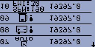
77 12 Alarms, Events and History Management Following alarms and records are available: Event Warnings Shutdowns ECU Messages Four records can be displayed simultaneously on the LCD screen. Total capacity is 10 records. The Figure 12.1 is an example of how the history is organized. The last screen in this example is showing the four latest events. To view further history records press button see Figure 12.1.For alarm (shutdown) confirmation press Stop button. Figure 12.1 InteliNano-NT Plus, SW version 1.4, ComAp March


78 Figure 12.2 InteliNano-NT Plus, SW version 1.4, ComAp March
InteliDrive Nano. Reference Guide. Engine Controller. InteliDrive Nano. Compact Controller for Industrial Engines. SW version 1.
 InteliDrive Nano InteliDrive Nano Engine Controller Compact Controller for Industrial Engines SW version 1.3, October 2012 Reference Guide Copyright 2012 ComAp s.r.o. ComAp, spol. s r.o. Kundratka 17,
InteliNano NT. Operator Guide. Copyright 2011 ComAp s.r.o.
 InteliNano NT Operator Guide Copyright 2011 ComAp s.r.o. ComAp, spol. s r.o. Kundratka 17, 180 00 Praha 8, Czech Republic Tel: +420 246 012 111, Fax: +420 266 316 647 E-mail: info@comap.cz, www.comap.cz
InteliNano NT. MRS Lite GEN-SET CONTROLLER. Description. Benefits
 GEN-SET CONTROLLER Description is a cost effective generator set controller which offers outstanding protection, monitoring and control for small and middle size generator sets. There are three different
InteliNano NT GEN-SET CONTROLLER. Description. Benefits MEMBER
 GEN-SET CONTROLLER Description is a cost effective diesel and gasoline generator set controller which offers outstanding protection, monitoring and control for small and middle size generator sets. There
Genset control and protection with safety system
 APPLICATION NOTES Generator Protection Unit, GPU-3 APPLICATION NOTES Genset control and protection with safety system Application description Functional description Wiring I/O lists Basic setup Flowcharts
TT /12b INSTALLATION INSTRUCTIONS. Introduction
 TT-1545 11/12b INSTALLATION INSTRUCTIONS Original Issue Date: 6/10 Model: 20-300 kw Generator Sets Market: Industrial Subject: Decision-Maker 3000 Controller Service Replacement Kit GM75376 Introduction
Comprehensive Modular Genset Controller
 Inteligen Learn More Comprehensive Modular Genset Controller Brief Description The Inteligen is a comprehensive controller for single and multiple generating sets operating in standby or parallel to the
DATA SHEET Compact Genset Controller, CGC 200
 DATA SHEET Compact Genset Controller, CGC 200 Auto start and parameter monitoring Warnings and shutdown protections Includes 5 digital inputs, 5 relay outputs Configurable for other applications Licence-free
Replacement of GCP-10 Series with easygen-1500 Application Note
 37338 Replacement of GCP-10 Series with easygen-1500 Application Note Application Note easygen-1500 Software Version 2.0xxx Manual 37338 WARNING Read this entire manual and all other publications pertaining
InteliPro. Protection Relay for Parallel Applications. Technical Specification
 InteliPro Protection Relay for Parallel Applications Product description InteliPro is a highly flexible interconnection/mains decoupling protective relay with extensive protective functions. It meets the
REFERENCE GUIDE. Copyright 2008 ComAp s.r.o.
 PC Software for Gen-set Controllers LiteEdit Monitoring Tool for ComAp Controllers To be used with ComAp controllers: IL MRSXX, IL AMFXX, IL-NT MRSXX, IL-NT AMFXX, IC-NT SPtM, IC-NT MINT, MC-NT and derived
InteliLite NT SINGLE SET GEN-SET CONTROLLER. Description. Benefits
 SINGLE SET GEN-SET CONTROLLER Description The range offers a wide choice of integrated control solutions for gen-sets operating in single standby mode. Based on the field proven InteliLite architecture,
InteliLite MRS17 Click Here to Learn More
 InteliLite MRS17 Click Here to Learn More Comprehensive Genset Controller Brief Description The InteliLite is a cost effective controller for generator sets in stand-by and prime power applications. The
Quick Start Guide TS A
 Quick Start Guide TS 930 125-630A DANGER HAZARD OF ELECTRICAL SHOCK, EXPLOSION, OR ARC FLASH Read and understand this quick start guide before installing and operating the transfer switch The installer
InteliPro. Installation and Operation Guide Application Guide Communication Brochure Reference Guide. Protection Relay for Parallel Applications
 InteliPro Protection Relay for Parallel Applications Comprehensive Guide SW version 1.6, November 2014 Installation and Operation Guide Application Guide Communication Brochure Reference Guide Copyright
HGM9580 Bus Tie Bus Parallel Unit USER MANUAL. Smartgen Technology
 HGM9580 Bus Tie Bus Parallel Unit USER MANUAL Smartgen Technology This manual is suitable for HGM9580 bus tie bus parallel unit only. Clarification of notation used within this publication. SIGN INSTRUCTION
Compact Genset Controller, CGC 400 Generator control and protection Engine monitoring and protection Generator and mains breaker control RS485 Modbus
 DATA SHEET Compact Genset Controller, CGC 400 Generator control and protection Engine monitoring and protection Generator and mains breaker control RS485 Modbus DEIF A/S Frisenborgvej 33 DK-7800 Skive
InteliLite NT SINGLE SET GEN-SET CONTROLLER. Description. Benefits
 SINGLE SET GEN-SET CONTROLLER Description The range offers a wide choice of integrated control solutions for gen-sets operating in single standby mode. Based on the field proven InteliLite architecture,
InteliLite SINGLE SET GEN-SET CONTROLLER. Description. Benefits
 SINGLE SET GEN-SET CONTROLLER Description AirGate Modern communications made simple. ComAp s powerful AirGate technology is provided in a range of our controllers and makes remote Internet connection to
M2500 Engine Controller Configuration Manual
 M2500 Engine Controller Configuration Manual Revision: 08-04-2011 Page 1 Contents 1 Preface... 4 2 Configuration from front panel... 5 2.1 Engine Controller Configuration... 6 2.1.1 RPM settings... 6 2.1.2
OPERATING INSTRUCTION
 OPERATING INSTRUCTION AUTORANGING MULTIMETER MAX Ω F C 10A MAX every 15 min. COM V SAFETY INFORMATION The following safety information must be observed to insure maximum personal safety during the operation
DEEP SEA ELECTRONICS PLC
 DEEP SEA ELECTRONICS PLC 7xx series configuration software for Windows Software Manual Author Anthony Manton Deep Sea Electronics Plc Highfield House Hunmanby Industrial Estate North Yorkshire YO14 0PH
Option M2 Configurable engine control cards Multi-line 2 version B SW version 2.4X.X
 Description of options Option M2 Configurable engine control cards Multi-line 2 version 2 4189340482B SW version 2.4X.X Description of options Functional description DEIF A/S Display units Additional functions
P216. Condenser fan speed controller. Product bulletin. Features
 P216 Condenser fan speed controller Product bulletin These controllers are designed for speed variation of single phase motors, especially for fan speed control on air cooled condensers. Head pressure
Compact Genset Controller, CGC 200 Mounting Terminals and wiring Commissioning, using the Utility Software and/or the front panel
 INSTALLATION AND COMMISSIONING INSTRUCTIONS Compact Genset Controller, CGC 200 Mounting Terminals and wiring, using the Utility Software and/or the front panel DEIF A/S Frisenborgvej 33 DK-7800 Skive Tel.:
DM-918 OPERATIONS MANUAL AUTORANGING MULTIMETER
 DM-918 OPERATIONS MANUAL AUTORANGING MULTIMETER SAFETY INFORMATION The following safety information must be observed to ensure maximum personal safety during the operation of this meter: This meter is
ÓÉ Foxit PDF Editor ±à¼ æè ËùÓÐ (c) by Foxit Software Company, 2004 ½öÓÃÓÚÆÀ¹À. Reference Guide
 by Foxit Software Company, 2004 ½öÓÃÓÚÆÀ¹À. Reference Guide") ÓÉ Foxit PDF Editor ±à¼ æè ËùÓÐ (c) by Foxit Software Company, 2004 ½öÓÃÓÚÆÀ¹À Reference Guide Table of Contents Table of Contents... 2 General Guidelines... 4 What describes this manual?... 4!! Warnings!!...
ÓÉ Foxit PDF Editor ±à¼ æè ËùÓÐ (c) by Foxit Software Company, 2004 ½öÓÃÓÚÆÀ¹À Reference Guide Table of Contents Table of Contents... 2 General Guidelines... 4 What describes this manual?... 4!! Warnings!!...
REFERENCE GUIDE. MainsCompact NT P Mains controller for the InteliCompact gen-set controllers. SW version 1.0, March Copyright 2008 ComAp s.r.o.
 MainsCompact NT P Mains controller for the InteliCompact gen-set controllers SW version 1.0, March 2009 REFERENCE GUIDE Copyright 2008 ComAp s.r.o. ComAp, spol. s r.o. Kundratka 17, 180 00 Praha 8, Czech
S-14 S-14. Compact Digital Multimeter. Compact Digital Multimeter
 S-14 Compact Digital Multimeter S-14 Compact Digital Multimeter SAFETY INFORMATION The following safety information must be observed to insure maximum personal safety during the operation at this meter
LiteEdit 2.0. User guide. Configuration and Monitoring Tool. PC Software for InteliLite Controllers. SW version 2.0, August 2004
 PC Software for InteliLite Controllers LiteEdit 2.0 Configuration and Monitoring Tool SW version 2.0, August 2004 User guide Copyright 2004 ComAp s.r.o. Written by Ladislav Kadaník Prague, Czech Republic
InteliLite NT AMF. Reference Guide. Modular Gen-set Controller. InteliLite NT. Compact Controller for Stand-by Operating Gen-sets
 InteliLite NT InteliLite NT AMF Modular Gen-set Controller Compact Controller for Stand-by Operating Gen-sets (IL-NT AMF20/25 unit) SW version 2.1, November 2012 Reference Guide Copyright 2012 ComAp s.r.o.
Digital Clamp-on Meter Amp Plus. Instruction Manual
 296 Digital Clamp-on Meter Amp Plus Instruction Manual TABLE OF CONTENTS A. INTRODUCTION 1. Congratulations...3 2. Product Description...3 3. Declaration of Conformity...4 B. SAFETY CONSIDERATIONS...5
InteliLite AMF. User guide. Modular Gen-set Controller. InteliLite. Compact Controller for Stand-by Operating Gen-sets. (IL-CU AMF20/25 unit)
") InteliLite InteliLite AMF Modular Gen-set Controller Compact Controller for Stand-by Operating Gen-sets (IL-CU AMF20/25 unit) SW version 2.2, November 2004 User guide Copyright 2004 ComAp s.r.o. Written
InteliLite InteliLite AMF Modular Gen-set Controller Compact Controller for Stand-by Operating Gen-sets (IL-CU AMF20/25 unit) SW version 2.2, November 2004 User guide Copyright 2004 ComAp s.r.o. Written
InteliLite NT MRSx AMFx
 InteliLite NT InteliLite NT MRSx AMFx Modular Gen-set Controller Compact Controller for Stand-by Operating Gen-sets (IL-NT-MRS3,4-AMF8,9) SW version 1.4, October 2008 Reference Guide Copyright 2008 ComAp
Accessory Modules. Reference Guide. Extension modules for IL-NT, IC-NT, ID-Lite genset or engine controllers, IA-NT. April ComAp, spol. s r.o.
 Extension modules for IL-NT, IC-NT, ID-Lite genset or engine controllers, IA-NT Accessory Modules April 2011 Reference Guide ComAp, spol. s r.o. Kundratka 2359/17, 180 00 Praha 8, Czech Republic Tel: +420
Digital Clamp-on Meter Instruction Manual
 255 Digital Clamp-on Meter Instruction Manual TABLE OF CONTENTS A. INTRODUCTION 1. Congratulations...3 2. Product Description...3 3. Declaration of Conformity...4 B. SAFETY CONSIDERATIONS...5 C. TECHNICAL
Autoranging True RMS Multimeter User Manual
 Autoranging True RMS Multimeter User Manual Please read this manual before switching the unit on. Important safety information inside. Contents Page 1. Safety Information... 4 2. Safety Symbols... 5 3.
Te 804 Electronic Controller. Service, Operation & Technical Information Manual
 Te 804 Electronic Controller Service, Operation & Technical Information Manual WARNING! Technical descriptions and data given in this document are accurate, to the best of our knowledge, but can be subject
DGC-2000 DIGITAL GENSET CONTROLLER
 DGC-2000 DIGITAL GENSET CONTROLLER Basler Electric s Digital Genset Controller (DGC-2000) offers an integrated alternative for genset control and monitoring. Control includes engine starting and shutdown
HMC9000A DIESEL ENGINE CONTROLLER (With J1939 Interface) USER MANUAL SMARTGEN (ZHENGZHOU) TECHNOLOGY CO.,LTD.
 USER MANUAL SMARTGEN (ZHENGZHOU) TECHNOLOGY CO.,LTD.") HMC9000A DIESEL ENGINE CONTROLLER (With J1939 Interface) USER MANUAL SMARTGEN (ZHENGZHOU) TECHNOLOGY CO.,LTD. Chinese trademark English trademark SmartGen make your generator smart SmartGen Technology
HMC9000A DIESEL ENGINE CONTROLLER (With J1939 Interface) USER MANUAL SMARTGEN (ZHENGZHOU) TECHNOLOGY CO.,LTD. Chinese trademark English trademark SmartGen make your generator smart SmartGen Technology
Genset Controller Unit Model EMS - GC10. Installation Manual Section
 Genset Controller Unit Model EMS - GC10 Installation Manual 00-02-0794 Section 75 2013-01-28 In order to consistently bring you the highest quality, full featured products, we reserve the right to change
HAT560NC SERIES (HAT560NC /HAT560NBC) ATS CONTROLLER USER MANUAL
 ATS CONTROLLER USER MANUAL") HAT560NC SERIES (HAT560NC /HAT560NBC) ATS CONTROLLER USER MANUAL SMARTGEN (ZHENGZHOU) TECHNOLOGY CO., LTD. Chinese trademark English trademark SmartGen make your generator smart SmartGen Technology Co.,
HAT560NC SERIES (HAT560NC /HAT560NBC) ATS CONTROLLER USER MANUAL SMARTGEN (ZHENGZHOU) TECHNOLOGY CO., LTD. Chinese trademark English trademark SmartGen make your generator smart SmartGen Technology Co.,
GE Power Management. MMII Intelligent MCC Controller
 A concept that will offer reduced overall installed cost and production efficiency through information availability to operators and maintenance. Presentation Overview 6 Applications 6 Protection and Control
Electrical Demand Specification (Reference SOP: )
") Project: Equipment Description: Location: Equipment No.: Project No: Protocol No.: Content Index 1. GENERAL...3 Design Standards...3 1.1. Standards...3 2. DESIGN...3 2.1. Safety...3 2.2. Circuit protection...3
Project: Equipment Description: Location: Equipment No.: Project No: Protocol No.: Content Index 1. GENERAL...3 Design Standards...3 1.1. Standards...3 2. DESIGN...3 2.1. Safety...3 2.2. Circuit protection...3
InteliLite NT MRS Modular Gen-set Controller User guide ComAp, spol. s r.o.
 InteliLite NT InteliLite NT MRS Modular Gen-set Controller Compact Controller for Single Operating Gen-sets (IL-NT MRS10/11/15/16 unit) SW version 1.0, August 2007 User guide Copyright 2007 ComAp s.r.o.
InteliLite NT MRS. Reference Guide. Modular Gen-set Controller. InteliLite NT. Compact Controller for Single Operating Gen-sets
 InteliLite NT InteliLite NT MRS Modular Gen-set Controller Compact Controller for Single Operating Gen-sets (IL-NT MRS10/11/15/16 unit) SW version 2.2, September 2014 Reference Guide Copyright 2014 ComAp
InteliATS NT. Reference Guide. Automatic Transfer Switch Controller. IA-NT STD unit. SW version 2.0, June 2010
 InteliATS NT Automatic Transfer Switch Controller IA-NT STD unit SW version 2.0, June 2010 Reference Guide June 2010 Copyright 2010 ComAp s.r.o. Written by Vlastimil Vostřák Prague, Czech Republic ComAp,
InteliATS NT. Reference Guide. Automatic Transfer Switch Controller. IA-NT PWR unit. SW version 2.0, June 2010
 InteliATS NT Automatic Transfer Switch Controller IA-NT PWR unit SW version 2.0, June 2010 Reference Guide June 2010 Copyright 2010 ComAp s.r.o. Written by Vlastimil Vostřák Prague, Czech Republic ComAp,
Application Note (Revision NEW) Original Instructions. EGCP-2 Differences
 Original Instructions. EGCP-2 Differences") Application Note 51199 (Revision NEW) Original Instructions General Precautions Read this entire manual and all other publications pertaining to the work to be performed before installing, operating, or
Application Note 51199 (Revision NEW) Original Instructions General Precautions Read this entire manual and all other publications pertaining to the work to be performed before installing, operating, or
5.1. Motor Protection and Monitoring. Contents. Product Overview. Monitoring Relays. D64R Series Digital Ground Fault Relays...
 .1 Ground Fault Relays and Monitors Contents Description Current.................. Phase................... Voltage.................. Ground Fault Relays and Monitors D64R Series Digital Ground Fault Relays....
Digital Clamp-on Meter Amp Plus. Instruction Manual
 293 Digital Clamp-on Meter Amp Plus Instruction Manual TABLE OF CONTENTS A. INTRODUCTION 1. Congratulations...3 2. Product Description...3 3. Declaration of Conformity...4 B. SAFETY CONSIDERATIONS...5
InteliLite NT AMF. User guide. Modular Gen-set Controller. InteliLite NT. Compact Controller for Stand-by Operating Gen-sets. (IL-NT AMF20/25 unit)
") InteliLite NT InteliLite NT AMF Modular Gen-set Controller Compact Controller for Stand-by Operating Gen-sets (IL-NT AMF20/25 unit) SW version 1.0, August 2007 User guide Copyright 2004 ComAp s.r.o. Written
InteliLite NT InteliLite NT AMF Modular Gen-set Controller Compact Controller for Stand-by Operating Gen-sets (IL-NT AMF20/25 unit) SW version 1.0, August 2007 User guide Copyright 2004 ComAp s.r.o. Written
Comprehensive Modular Genset Controller
 InteliGen Comprehensive Modular Genset Controller Brief Description InteliGen is a comprehensive AMF-controller for single and multiple generating sets operating in standby or parallel modes. A modular
DEEP SEA ELECTRONICS PLC
 COMPLEX SOLUTIONS MADE SIMPLE DEEP SEA ELECTRONICS PLC DSE705 ATS CONTROL MODULE OPERATING MANUAL Deep Sea Electronics Plc Highfield House Hunmanby North Yorkshire YO14 0PH ENGLAND Sales Tel: +44 (0) 1723
Owner s Manual Revision 4.01 Option 1
 Owner s Manual Revision 4.01 Option 1 Special Version of the SW series Inverter / Charger for Motor Coach Applications Part # 2031-7 (Supplement to Normal Manual) Effective Date: April 17, 1996 Trace Engineering
STANDARD SUBMITTAL PACKAGE
 STANDARD SUBMITTAL PACKAGE SBP1000-51( ) FTA1000 Full Voltage Starting Electric Fire Pump Controllers Product Description Description Firetrol FTA1000 Full Voltage Fire Pump Controllers are intended for
InteliLite NT SINGLE SET GEN-SET CONTROLLER. Description. Benefits MEMBER
 SINGLE SET CONTROLLER Description The range offers a wide choice of integrated control solutions for gen-sets operating in single standby mode. Based on the field proven InteliLite architecture, the family
DEEP SEA ELECTRONICS PLC
 COMPLEX SOLUTIONS MADE SIMPLE. DEEP SEA ELECTRONICS PLC DSE5520 AUTOMATIC MAINS FAILURE CONTROL MODULE OPERATING MANUAL Deep Sea Electronics Plc Highfield House Hunmanby North Yorkshire YO14 0PH ENGLAND
3700 SERIES USER MANUAL
 SAFETY GUIDE This manual contains the precautions necessary to ensure your personal safety as well as for protection for the products and the connected equipment. These precautions are highlighted with
Installation, Operation and Maintenance Manual
 Document 481200 VGD-100 Vari-Green Drive Installation, Operation and Maintenance Manual Please read and save these instructions for future reference. Read carefully before attempting to assemble, install,
CA-A480-A Elevator Controller. Reference & Installation Manual
 CA-A480-A Elevator Controller Reference & Installation Manual TABLE OF CONTENTS INTRODUCTION.................................................................. 4 Introduction.............................................................................................
Operating instructions. Switching amplifier DN0210 DN / / 2015
 Operating instructions Switching amplifier DN0210 DN0220 UK 80011079 / 00 01 / 2015 Contents 1 Preliminary note...4 1.1 Symbols used...4 1.2 Warning signs used...4 2 Safety instructions...5 2.1 General...5
DEEP SEA ELECTRONICS PLC
 COMPLEX SOLUTIONS MADE SIMPLE. DEEP SEA ELECTRONICS PLC DSE4130 AUTOMATIC TRANSFER SWITCH CONTROL MODULE OPERATING MANUAL Deep Sea Electronics Plc Highfield House Hunmanby North Yorkshire YO14 0PH ENGLAND
InteliLite NT SINGLE SET GEN-SET CONTROLLER. Description. Benefits
 SINGLE SET CONTROLLER Description The range offers a wide choice of integrated control solutions for gen-sets operating in single standby mode. Based on the field proven InteliLite architecture, the family
HAT162 ATS CONTROLLER USER MANUAL
 HAT162 ATS CONTROLLER USER MANUAL SMARTGEN (ZHENGZHOU) TECHNOLOGY CO.,LTD. Chinese trademark English trademark SmartGen make your generator smart SmartGen Technology Co., Ltd. No. 28 Jinsuo Road Zhengzhou
PQ V ac. CONTROL PANEL 230V FOR ROLLING SHUTTERS Instructions Manual. Control panel for electric rolling shutters 230Vac TECHNICAL FEATURES
 CONTROL PANEL 230V FOR ROLLING SHUTTERS Instructions Manual Q45 230V ac Control panel for electric rolling shutters 230Vac Built-in radio receiver 433Mhz Adjustable pause time for automatic closing function
DSEULTRA DSE3110 Series Control Module
 DSEULTRA DSE3110 Series Control Module 057-086 Author : Anthony Manton DSE Model 3000 Series Control and Instrumentation System Operators Manual Deep Sea Electronics Plc Highfield House Hunmanby North
Operating instructions. Standstill monitor A / / 2011
 Operating instructions Standstill monitor A300 UK 1 2 3 4 5 6 7 8 7390337 / 01 02 / 2011 1 2 3 4 5 6 7 8 switchpoint min max pulse/min power Made in Germany ifm electronic gmbh D 45127 Essen func. I II
Generator Controller GC-1
 4921240293F Standard functions DEIF A/S Engine control Start preparation (preheater or prelubrication) Start/stop sequences with selectable no. of start attempts Fuel solenoid selection (coil type) Idle
Wiring Instructions for Replacement of 2301A Load Sharing and Speed Controls with 2301D Load Sharing and Speed Controls
 Application Note 51242 (Revision NEW) Original Instructions Wiring Instructions for Replacement of 2301A Load Sharing and Speed Controls with 2301D Load Sharing and Speed Controls General Precautions Read
HVD300 VOLTAGE DETECTION RELAY MULTIFUNCTIONAL PROTECTION MODULE USER MANUAL
 HVD300 VOLTAGE DETECTION RELAY MULTIFUNCTIONAL PROTECTION MODULE USER MANUAL SMARTGEN (ZHENGZHOU) TECHNOLOGY CO.,LTD. Chinese trademark English trademark Smartgen make your generator smart Smartgen Technology
ACOPOSinverter P74. User's Manual. Version: 2.20 (August 2016) Model no.: Original instruction
 Model no.: Original instruction") ACOPOSinverter P74 User's Manual Version: 2.20 (August 2016) Model no.: MAACPIP74-ENG Original instruction All information contained in this manual is current as of its creation/publication. We reserve
ACOPOSinverter P74 User's Manual Version: 2.20 (August 2016) Model no.: MAACPIP74-ENG Original instruction All information contained in this manual is current as of its creation/publication. We reserve
Operating instructions. Speed monitor D / / 2014
 Operating instructions Speed monitor D200 80005257 / 00 05 / 2014 Contents 1 Preliminary note...4 1.1 Symbols used...4 1.2 Warning signs used...4 2 Safety instructions...5 2.1 General...5 2.2 Target group...5
DIN16A DIGITAL INPUT MODULE USER MANUAL
 DIN16A DIGITAL INPUT MODULE USER MANUAL SMARTGEN (ZHENGZHOU) TECHNOLOGY CO.,LTD. Chinese trademark English trademark SmartGen make your generator smart SmartGen Technology Co., Ltd No. 28 Jinsuo Road Zhengzhou
MAINTENANCE MANUAL. EDACS REDUNDANT POWER SUPPLY SYSTEM 350A1441P1 and P2 POWER MODULE CHASSIS 350A1441P3, P4, AND P5 POWER MODULES TABLE OF CONTENTS
 MAINTENANCE MANUAL EDACS REDUNDANT POWER SUPPLY SYSTEM 350A1441P1 and P2 POWER MODULE CHASSIS 350A1441P3, P4, AND P5 POWER MODULES TABLE OF CONTENTS SPECIFICATIONS*... 2 INTRODUCTION... 3 DESCRIPTION...
SOLARIMMERSION IV Advanced Installation Manual v1.9
 SOLARIMMERSION IV Advanced Installation Manual v1.9 1 Contents 1. Overview 2. Technical Specifications 3. Installation Mounting Electrical Installation Clamp Installation Wiring Diagrams 4. Installation
Manual# Installation Manual. 400E Series. DCU 410E Engine Control Unit RP 410E Remote Panel
 Manual# 1100346 Installation Manual 400E Series DCU 410E Engine Control Unit RP 410E Remote Panel RP 410E DCU 410E Installation Manual for Marine Pro 400E Series ~~~ DCU 410E Engine Control Unit RP 410E
MiG2 CONTROLLERS. 2 & 4 Stage General Purpose Controllers, with Air-conditioning Facilities
 MiG2 CONTROLLERS 2 & 4 Stage General Purpose Controllers, with Air-conditioning Facilities The MiG2 controllers incorporate: 2 Inputs (Configurable as Resistive, 0 10V, 0 20mA or 4 20mA) 2 or 4 Relay Outputs
Tap Manager TM100. Operating Instructions
 Tap Manager TM100 Operating Instructions 2 Contents Contents 1 General... 5 1.1 Safety instructions... 5 1.2 Application... 5 2 Design... 6 2.1 Controls... 6 2.1.1 Scroll keys in display field... 6 2.1.2
FTA1350 WYE-DELTA CLOSED FIRE PUMP CONTROLLERS STANDARD SUBMITTAL PACKAGE
 FTA1350 WYE-DELTA CLOSED FIRE PUMP CONTROLLERS STANDARD SUBMITTAL PACKAGE NOTE: The drawings included herein are for standard controllers. Actual "as built" drawings may differ from those seen here. ASCO
GSC400 PC INTERFACE SOFTWARE MANUAL. Installation and User Manual for the GSC400 PC Software Interface
 4016 Quartz Drive Santa Rosa, CA 95405 Phone: 707 539-9003 Fax: 707 539-5212 Email: sales@generatorjoe.net Web www.generatorjoe.net GSC400 PC INTERFACE SOFTWARE MANUAL Installation and User Manual for
No longer for sale. Generator Controller GC-1. Data sheet. Standard functions
 4921240293F DEIF A/S Engine control Start preparation (preheater or prelubrication) Start/stop sequences with selectable no. of start attempts Fuel solenoid selection (coil type) Idle speed control Local
Installation Manual. Multi Power Controller MPC-1 multi-line D
 Installation Manual Multi Power Controller MPC-1 multi-line Complete control system in one package: - island operation - parallel with mains operation - emergency generator control 3-phase AC measurements
Resolver to Digital Expansion Board
 Resolver to Digital Expansion Board Catalog No. EXB009A01 Installation and Operating Manual 6/98 MN1313 Table of Contents Section 1 General Information............................. 1-1 Introduction....................................
Compact Genset Controller, CGC 400 What's in the delivery? The first steps Push-buttons and LEDs
 QUICK START GUIDE Compact Genset Controller, CGC 400 What's in the delivery? The first steps Push-buttons and LEDs DEIF A/S Frisenborgvej 33 DK-7800 Skive Tel.: +45 9614 9614 Fax: +45 9614 9615 info@deif.com
GCI-5K INSTALLATION AND OPERATOR S MANUAL
 GCI-5K INSTALLATION AND OPERATOR S MANUAL Grid-tied inverter for wind Ningbo Ginlong Technologies 1 INTRODUCTION 2 SAFETY GUIDELINES AND WARNINGS 3 INSTALLATION 3.1 Selecting a location for the inverter
AUTOMATIC TRANSFER SWITCH CONTROLLERS ATL SERIES
 AUTOMATIC TRANSFER SWITCH CONTROLLERS ATL SERIES 2 power sources automatic transfer switch controllers The automatic transfer switch controllers ATL 600 - ATL 610 - ATL 800 can supervise and manage the
P216 Series Condenser Fan Speed Controller
 P216 Series Condenser Fan Speed Controller Installation Instructions P216xxx-x Part No. 24-85895-18, Rev. D Issued 27 August 2015 Applications Refer to the QuickLIT website for the most up-to-date version
Option H3 Serial communication Profibus DP
 MULTI-LINE 2 DESCRIPTION OF OPTIONS Option H3 Serial communication Profibus DP Description of option Functional description Parameters Data tables Document no.: 4189340443H Multi-line 2 Option H3, Serial
HGM9510 Genset Parallel (With Genset) Unit USER MANUAL. Smartgen Technology
 Unit USER MANUAL. Smartgen Technology") HGM9510 Genset Parallel (With Genset) Unit USER MANUAL Smartgen Technology CONTENTS 1 OVERVIEW... 5 2 MODULES COMPARISON... 6 3 PERFORMANCE AND CHARACTERISTICS... 7 4 SPECIFICATION... 9 5 OPERATION...
HGM9510 Genset Parallel (With Genset) Unit USER MANUAL Smartgen Technology CONTENTS 1 OVERVIEW... 5 2 MODULES COMPARISON... 6 3 PERFORMANCE AND CHARACTERISTICS... 7 4 SPECIFICATION... 9 5 OPERATION...
DEEP SEA ELECTRONICS PLC
 DEEP SEA ELECTRONICS PLC DSE60xx Series Control Module Document Number 057-112 Author : Anthony Manton http://bestgenerator.spb.ru/?page_id=6765 DSE Model 60xx Series Control and Instrumentation System
Safety Instructions 1-1 Avoid unintended Start General Description 2-2
 Contents Contents 1 Safety and precautions 1-1 Safety Instructions 1-1 Avoid unintended Start. 1-1 2 Introduction 2-1 General Description 2-2 3 Supported Configuration 3-1 Introduction 3-1 Fixed-speed
Generator Controller GC-1F
 Controller 4921240310D Standard functions DEIF A/S Engine control Start preparation (preheating or prelubrication) Start/stop sequences with selectable no. of start attempts Fuel solenoid selection (coil
PowerWizard 1.1, 1.1+ & & 2.1 Generating Set Control Technical Manual
 PowerWizard 1.1, 1.1+ & & 2.1 Generating Set Control Technical Manual Contents Important Safety Information 5 1. General Information 6 1.1 Introduction... 6 1.2 Applications... 6 1.3 PowerWizard Variations...
Digital Clamp-on Meter Instruction Manual
 265 Digital Clamp-on Meter Instruction Manual TABLE OF CONTENTS A. INTRODUCTION 1. Congratulations...3 2. Product Description...3 3. Declaration of Conformity...4 B. SAFETY CONSIDERATIONS...5 C. TECHNICAL
Using the proconx GCP-MG Communication Gateway with the GCP-30 and LS-4 Controls. Application Note 51306
 Using the proconx GCP-MG Communication Gateway with the GCP-30 and LS-4 Controls Application Note 51306 WARNING DANGER OF DEATH OR PERSONAL INJURY WARNING FOLLOW INSTRUCTIONS Read this entire manual and
User Manual. 400Amp AC Clamp Meter + NCV. Model MA430. Additional User Manual Translations available at
 User Manual 400Amp AC Clamp Meter + NCV Model MA430 Additional User Manual Translations available at www.extech.com Introduction Congratulations on your purchase of this Extech MA430 Clamp Meter. This
HT-DST4602 Evolution. Genset Controller. AMF and PARALLEL genset controller. Parallel Applications HUEGLI TECH SWITZERLAND
 HT-DST4602 Evolution Parallel Applications 7 color TFT display (800 x 480 pixel) Split and Compact Version PLC functions included with PID blocks True RMS measure for both sources current & voltage Active
DCS-E 1kW Series, DLM-E 3kW & 4kW Power Supplies
 DCS-E 1kW Series, DLM-E 3kW & 4kW Power Supplies M51A Option: Isolated Analog Programming Manual Power Supplies Elgar Electronics Corporation 9250 Brown Deer Road San Diego, CA 92121-2294 1-800-73ELGAR
PLT. Breaker-based transfer switch open, closed or soft transition amps. Specification sheet
 Specification sheet PLT Breaker-based transfer switch open, closed or soft transition 800 3000 amps Description PLT breaker-based transfer switches are designed for operation and switching of electrical