Cipher 1023 Magnetic Stripe Reader Installation and User's Guide. Document Number : Released Date : Dec 2, 1996
|
|
|
- Rosamond Briggs
- 5 years ago
- Views:
Transcription
1 Cipher 1023 Magnetic Stripe Reader Installation and User's Guide Document Number : Released Date : Dec 2, 1996
2 WARNING Note: This equipment has been tested and found to comply with the limits for a Class A digital device, pursuant to Part 15 of FCC Rules. These limits are designed to provide reasonable protection against harmful interference in a residential installation. This equipment generates, uses and can radiate radio frequency energy and, if not installed and used in accordance with the instructions, may cause harmful interference to radio communications. However, there is no guarantee that interference will not occur in a particular installation. If this equipment does cause harmful interference to radio or television reception, which can be determined by turning the equipment off and on, the user is encouraged to try correct the interference by one or more of the following measures: Reorient or relocate the receiving antenna. Increase the separation between the equipment and receiver. Connect the equipment into an outlet on a circuit different from that to which the receiver is connected. Consult the dealer or an experienced radio/tv technician for help.
3 Nomenclature Switches for settings Bottom View Interface Connector for connecting Interface Cable Top View Dual-Color LED for Power/Good Read
4 Table of Contents 1. INTRODUCTION MODELS BUZZER AND LED INDICATOR INTERFACE CONNECTOR AND INTERFACE CABLE CONFIGURING INTERFACE PARAMETERS PROGRAMMABLE FEATURES SETUP PROGRAM AVAILABLE INTERFACE CABLES DIP SWITCH QUICK LOOK-UP PHYSICAL SPECIFICATION PACKING LIST... 38
5 1. Introduction The Cipher 1023 is the ultimate solution for Magnetic Stripe Reading. The decoder, MSR reading heads and selection of output interfaces are included in a single unit. Support for up to 3 track reading and transmission of decoded data to the computer via RS232 or keyboard interface. This reader is designed with features to provide the functionality and flexibility needed to meet even the most complex application needs, with emphasis on easy installation and configuration. For most MSR applications, it is only necessary to adjust the switches at the bottom of the 1023 to complete the configuration. For those applications that need more advanced features (such as prefix, postfix, and editing mode, etc.), by connecting the 1023 to a computer serial port in RS232 mode the user can then configure the unit using the MSR (optional) setup program. IMPORTANT Syntech Information has made every possible effort to make sure that the 1023 and this manual is complete and correct. However, Syntech Information shall not be liable for any technical or editorial error and omissions. Syntech reserves the right to change any specification at any time without prior notice
6 Models The 1023 MSR comes in 6 different models. The difference is in the magnetic reading head assembled inside the 1023 MSR. The following list shows which type of reading head is equipped in each model. Please check the model number upon ordering / receiving the 1023 MSR : ISO Track : ISO Track : ISO Track : ISO Track 1 & : ISO Track 2 & : ISO Track 1, 2 & 3 Note: In this manual the phrase first track does not necessarily refer to ISO Track 1, but rather the first track of the reading head assembled in the For example, on the first track is the ISO Track 2, and the second track is the ISO Track
7 3. Buzzer and LED Indicator The 1023 has a dual color LED and a buzzer to indicate various operating states. The color of the LED indicator will be red when in normal state except for the following conditions. Power On: The LED will turn green and the buzzer will be on for 1 second to indicate successful power on. The LED will then turn to red normal status. Successful Reading : The LED will turn green and the buzzer will be on for 250 ms when there is a successful read. The LED will then turn to red normal status. Configuration Mode : There will be 6 beeps from the 1023 MSR when entering the configuration mode. The LED will stay green as long as it is in configuration mode
8 4. Interface Connector and Interface Cable The DB-15 female connector at the side of 1023 MSR is the Interface Connector. The interface connector when connected with the appropriate cable allows connection to various serial devices and keyboard types. The detailed description of each available interface cable is depicted in the section Available Interface Cables. Note : When ordering / receiving Interface Cables, please be sure that the part number is correct. Pin Assignment of the Interface Connector : Pin 1 : No Connection Pin 2 : RS232 RxD (port A) Pin 3 : RS232 RxD (port B) / CTS (port A) Pin 4 : RS232 TxD (port A) Pin 5 : RS232 TxD (port B) / RTS (port A) Pin 6 : +5V input Pin 7 : PC CLK Pin 8 : PC DATA Pin 9 : KBD CLK Pin 10 : KBD DATA Pin 11 : KBD Aux Pin 12 : Wyse CLK Pin 13 : Wyse PC DATA Pin 14 : Wyse KBD DATA Pin 15 : Ground - 4 -
9 5. Configuring Interface Parameters The interface parameters are configured by selecting switches at the bottom of 1023 MSR. The switches are named from SW1 to SW9. Each switch can only be set to either ON or OFF position. Every time the switch settings are changed, the 1023 must be powered off and back to on again to make the new settings effective. The 1023 MSR can transmit data to either a keyboard port or an RS232 port of the host computer. If configuring the 1023 MSR as a keyboard wedge reader, refer to section 5.1. Or refer to section 5.2, if the 1023 MSR is to be used as an RS232 reader. 5.1 Configuring Keyboard Interface Parameters SW1 : This switch must be in OFF position. SW2 : Capital Lock Status The 1023 needs to know the capital lock status of the keyboard the user is using. If this switch is incorrectly set then the 1023 will transmit alphabetic letters in the opposite case. ON OFF Capital Lock is in on position. Capital Lock is in off position
10 SW3 - SW8 : Keyboard Type ON ON ON ON ON ON PCAT (US), IBM 001-2, 002-2, OFF ON ON ON ON ON PCAT (French) ON OFF ON ON ON ON PCAT (German) OFF OFF ON ON ON ON PCAT (Italian) ON ON OFF ON ON ON PCAT (Belgium) OFF ON OFF ON ON ON PCAT (Norwegian/Swedish) ON OFF OFF ON ON ON PCAT (UK) OFF OFF OFF ON ON ON PCAT (Spanish) ON ON ON OFF ON ON NEC 5200 OFF ON ON OFF ON ON NEC 9800 ON OFF ON OFF ON ON DEC VT220 OFF OFF ON OFF ON ON Macintosh ADB ON ON OFF OFF ON ON Macintosh RJ OFF ON OFF OFF ON ON Memorex Telex (IBM Terminals) ON OFF OFF OFF ON ON Hitachi Elles OFF OFF OFF OFF ON ON PCXT ON ON ON ON OFF ON IBM A01-1 OFF ON ON ON OFF ON IBM A01-2 ON OFF ON ON OFF ON IBM A01-3 OFF OFF ON ON OFF ON IBM 001-1, 002-1, 003-1, PS2-30 ON ON OFF ON OFF ON IBM , , OFF ON OFF ON OFF ON IBM , ,
11 ON OFF OFF ON OFF ON IBM 001-8A, 002-8A, 003-8A OFF OFF OFF ON OFF ON IBM ON ON ON OFF OFF ON IBM 002-3, OFF ON ON OFF OFF ON IBM 3477 Type 4 (Japanese Keyboard) ON OFF ON OFF OFF ON IBM 5550 OFF OFF ON OFF OFF ON WYSE Enhance Keyboard (US) ON ON OFF OFF OFF ON NEC Astra OFF ON OFF OFF OFF ON Unisys ON OFF OFF OFF OFF ON Televideo 965 OFF OFF OFF OFF OFF ON ADDS 1010 ON ON ON ON ON OFF PCAT (Portuguese) SW9 : Inter-Character Delay To slow down the transmission of data to the computer's keyboard interface, a 25 ms delay between each data character occurs. ON OFF 25 ms Inter-Character Delay No Inter-Character Delay - 7 -
12 5.2 Configuring RS232 Interface Parameters SW1 : This switch must be in ON position. SW2 : Data Bits ON 8 Data Bits OFF 7 Data Bits SW3 - SW4 : Parity ON ON No Parity OFF ON Even Parity ON OFF Odd Parity SW5 - SW6 : Baud Rate ON ON bps OFF ON bps ON OFF 9600 bps OFF OFF 2400 bps - 8 -
13 SW7 - SW9 : Transmission Mode There are 6 transmission modes supported by the RS-232 interface. They are classified into two groups either Single Port or Dual Port mode. The Single Port operation is where the 1023 MSR is connected directly to the RS232 communication port of the computer. Whereas the Dual Port operation connects transparently in-line between the host computer and a terminal. The interface cable has two RS-232 connectors labeled A and B, one connects to the terminal and one connects to host cable. The transmission modes supported for Single Port and Dual Port operation are grouped below. Dual Ports Operation : Transmits data to Port A only. Transmits data to Port B only. Transmits data to both Port A and Port B. Single Port Operation : No RTS/CTS hand-shaking. Data Ready Mode : The RTS/CTS hand-shaking is enabled, and the RTS signal will be ON only when there is data to be transmitted
14 Scanner Ready Mode : The RTS/CTS hand-shaking is enabled, and the RTS signal stays ON all the time (as long as the power is applied). ON ON ON Transmit data to RS-232 Port A only (Dual Ports Operation) OFF ON ON Transmit data to RS-232 Port B only (Dual Ports Operation) ON OFF ON Transmit data to Both RS-232 Port A and B (Dual Ports Operation) OFF OFF OFF No RTS/CTS Hand-Shake (Single Port Operation) OFF OFF ON Data Ready (Single Port Operation) ON ON OFF Scanner Ready (Single Port Operation)
15 6. Programmable Features Besides the interface parameters, there are other programmable features that can be configured on the 1023 MSR. Most of these features are used to control the format of the output data, others are for controlling buzzer, inter-character delay, track decoding and others as listed below. All the programmable features described in this section can only be configured by using the optional setup program. This program runs under Microsoft Windows and communicates with the 1023 MSR through the RS232 (COM) port. Refer to section 7 for details on how to use the setup program. 6.1 Beeper Volume There are four different beeper volumes to select from on 1023 MSR. The default beeper volume is set to maximum. No Beep Maximum Volume Medium Volume Minimum Volume
16 6.2 Auxiliary Inter-Character Delay Besides the 25 ms inter-character delay which can be selected by setting SW9 (keyboard interface only), extra delay can be added by programming this setting. This setting works not only on the keyboard interface but also works on RS-232 interface. The default setting is 0 ms. 6.3 Capital Lock Auto-Detection (Keyboard Interface only) The 1023 MSR can be configured to detect the capital lock status of the keyboard automatically upon transmission of data. This setting is effective only when the keyboard type is either PCAT (all languages), PS2-30, PS55, or Memorex Telex (IBM terminals). If one of the above keyboard types is selected and this setting is enabled, the 1023 MSR will auto-detect the capital lock status and ignore the setting of SW2. Otherwise, the 1023 MSR will assume the capital lock status configured by SW2 when transmitting data. The default setting is disable. Note : There are some PCs or terminals that do not strictly conform to the standard PCAT keyboard interface. The 1023 MSR may fail to detect the capital lock status and lock the keyboard, when transmitting the data. If this happens then this setting must be disabled
17 6.4 Transmit Start / Stop Characters The 1023 MSR will transmit the start and stop character for each track of data by default. To stop the 1023 from transmitting these characters, this setting should be set to disable. The start and stop characters for each track are listed below. Start Stop ISO Track1 %? ISO Track2 ;? ISO Track3 ;? 6.5 Reverse Track Alignment The 1023 MSR by default will transmit the decoded data in the following sequence : first track, second track, and then the last track. If this setting is enabled, the 1023 will reverse this sequence. It will transmit the last track of data first and then the second track and finally the first track. 6.6 Direct Scan Code (Keyboard Interface only) The 1023 MSR can be configured to treat all user programmable fields (strings) as scan codes and thus bypass the code re-mapping process. This setting is effective only when the keyboard type is either
18 PCAT, PS55, PS2-30 or Memorex Telex (IBM terminals). The user programmable fields/strings include prefix code, interfix code, postfix code, and additional fields of editing format. The default setting is disable. 6.7 No Read Message Enable this setting will make the 1023 MSR transmit a "NO READ" message whenever there is a read failure. The default setting is disable. 6.8 Track Reading / Decoding User can control the reading/decoding of all three tracks individually by configuring these settings. For example, if the setting of Track1 Reading is not enabled, the 1023 MSR will not decode the track1 and so data will not be transmitted for that track. The default settings are enable. 6.9 Prefix, Interfix, and Postfix Codes The interfix code is inserted automatically by 1023 MSR between the tracks of data when more than 1 track of data is decoded. When decoding two tracks of data the 1023 MSR inserts the interfix code between the first and the second track. If all three tracks are decoded, the interfix code will be inserted between the first track and the second track, then between second track and the last track. Whereas, the
19 prefix code and the postfix code, as their names imply, are attached before the first track and after last track as data is transmitted. Up to 4 characters can be configured for each of these user programmable fields. The default settings for prefix and interfix code are empty, with the postfix code being the Return (Enter) character Editing Mode The 1023 MSR can be configured to re-arrange the data into another form before it is sent to the host computer. This is done by configuring an editing format for the 1023 MSR. The 1023 MSR transforms the decoded data (whenever applicable) according to the formats configured in the editing mode. Users can configure up to two co-existing editing formats and have the ability to enable or disable the formats individually. Each editing format can have conditions set which allows the data to be manipulated into fields, these fields can then be added to and transmitted in the order specified by the user. Note : The interfix code is inserted before processing the editing formats. That is, the interfix code is already inside the data being processed by the editing formats. Whereas the prefix and postfix codes are added after the editing formats have been applied
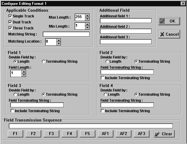
20 Applicable Conditions These conditions are used to qualify the data to be processed. Data must comply with the applicable conditions configured before the particular editing format can be applied. There are three applicable conditions that can be set for each editing format. Data Type : User can specify what kinds of data (single track, dual track, and/or three track) can be processed by this format. All of them can be enabled or disabled simultaneously or in any combination. Note : Here the phrase single track, dual track, and three track do not refer to the track number but rather the total number of tracks being decoded. Data Length : This setting specifies the maximum and minimum length (character count) of the data allowed for the editing format. If both maximum and minimum length is set at zero, the data length qualification is ignored. Matching String and Matching Location : User can specify a particular string (up to 3 characters) that must exist in the data to allow format processing. User can also specify the location of this string in the data by configuring the Matching Location. If the Matching Location is zero, the 1023 will only check for the existence of the Matching String (no matter where it is in the data)
21 Dividing Fields Data can be divided up into 5 fields (they are numbered Field1 to Field5 accordingly, referred to by abbreviation as F1 to F5. Although there can be a total of 5 fields, users only need to configure 4 fields as the last field is automatically assigned and sent. So the total number of fields is always one more than the number of fields actually configured. There are two ways to divide the fields : by specifying field terminating string, or by specifying field length (character count). Which method is used to divide data is somewhat application dependent, and it is not necessary to configure all fields by the same method. Dividing Fields by Field Terminating String : Fields can be divided by specifying the field terminating string. The field will continue until the occurrence of the specified string and the user can also decide whether the field terminating string is to be discarded (not included in current field and not in the next field). Up to two characters can be specified for this string. Dividing Fields by Field Length : Fields can be divided by simply specifying the length of the field
22 Additional Fields User can create additional fields, up to 3 additional fields for each editing format (they are numbered from Additional Field 1 to Additional Field 3 accordingly, referred to by abbreviation as AF1 to AF3. Each additional field can hold up to 3 characters Field Transmission Sequence After applicable conditions, data fields, and additional fields are configured, user can now configure what fields (F1 to F5, and AF1 to AF3, if configured) are to be transmitted. These fields can be transmitted in any order and in any combination. It is not necessary to send all the fields of data as some may not be required, the same field can be transmitted more than once. Up to 10 fields can be configured for this Field Transmission Sequence setting. The 1023 MSR will follow the field sequence configured and build the data string in that order when transmitting data Exclusive Data Editing The 1023 MSR will try to apply editing formats to each string of decoded data. If the formats specified do not meet the data read from card, the data will be transmitted as is (the prefix, interfix,
23 and postfix are still added) by default. If the Exclusive Data Editing setting is enabled, no data will be transmitted if the data read from the MSR card does not match what is expected, this means a complete match is required to allow data to be output Examples Example 1 : Extracts data from the 10th character to the 19th character. Field 1 : Divide field by field length, set field length to 9 Field 2 : Divide field by field length, set field length to 10 Field Transmission Sequence : F2 Example 2 : Extract the ID number, employee name, and account number from ID card. Data is encoded in the magnetic card like this : From the first character to the 10th character is the ID number. From the 11th character is the employee name, it is a variable length but is delimited by a ^ character, after the ^ character is the account number. Data should be transmitted like this : Employee name first, then a TAB character, followed by the ID number, then another TAB character and finally the account number
24 Field 1 : Divide field by field length, set the field length to 10. Field 2 : Divide field by field terminating string, set terminating string to ^ and clear the include terminating string check box. Additional Field 1 : Set to one TAB character. Field Transmission Sequence : F2 AF1 F1 AF1 F3-20 -
25 7. Setup Program This section describes the optional setup program for configuring the 1023 MSR. This program must be run under Microsoft Windows (3.1 or 95). And there should be an available serial port on the PC for the setup program to communicate with 1023 MSR. What follows is a list of what is needed to perform the configuration. The setup program 1023 MSR Unit PC which is running Microsoft Windows with available serial port RS232 Interface cable for connecting 1023 to the serial port of PC Power adapter or a power sharing cable used to provide power to 1023 MSR. Master card to put the 1023 into configuration mode. 7.1 Installation This setup program consists of the following four files. The first three are the program files, and the last one is the configuration file that stores the default settings of V3.EXE : Main program BIVBX11.DLL : Dynamic link library
26 MSCOMM.VBX : Custom control file for the setup program DEFAULT.MSR : Default configuration file Create a new directory or folder and copy all the files from the floppy disk to the newly created directory on the hard disk. 7.2 Start Up The setup program is started from windows by clicking on File and select Run. Enter the directory and the 1023V3.EXE program name. There should be an available serial port on the PC, or the following message will be showed. This setup program tries to find the available serial port from COM1 to COM4, and it assumes the 1023 MSR is connected to the first available serial port it finds. If the 1023 MSR is not connected to that

27 serial port or not in the configuration mode, the following message will be shown. To put the 1023 MSR into configuration mode, the master card must be swiped. The 1023 will beep six times on entering setup mode. If the setup program successfully finds the 1023 MSR, the following message will be shown on the display (the 1023 MSR will also beep twice)

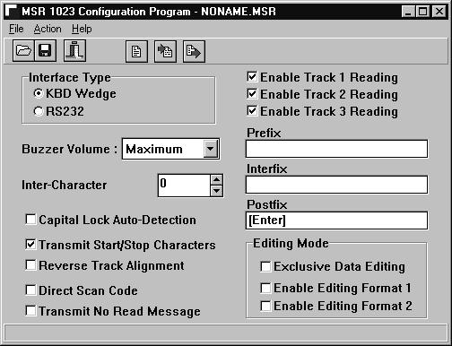
28 7.3 Main Window The main window of the setup program is like this
29 - 25 -
30 There is a tool bar below the menu with several command buttons that provide for easy selections. Alternatively the user can select from the menu bar options. This program will provide help when the mouse pointer is positioned on some of the settings or buttons. 7.4 Configuration File Configuration settings can be saved into files which always have the file extension MSR. The setup program starts with the default configuration file NONAME.MSR. The file name of the active configuration file is shown on the caption of the main window. If a previously saved file is opened the screen displays the caption and the settings of that file. Do not modify the DEFAULT.MSR file as the default settings will be changed if the file is modified, it is recommended that the file attribute of this file be set to Read Only. 7.5 Restore Default Settings To restore all settings on PC screen to their default values, press the Default button. The 1023 MSR is restored to default settings, by pressing the default button and then pressing the download button that loads the default settings
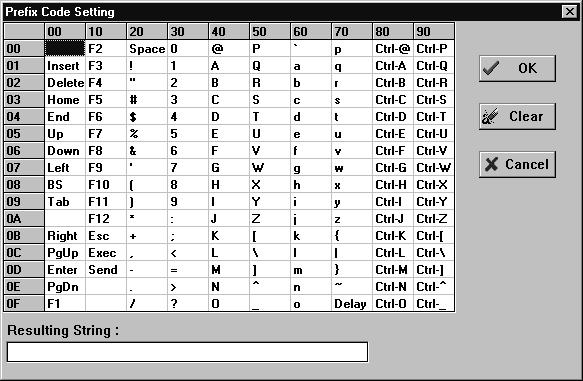
31 7.6 Select Interface Type The setup program needs to know the interface type to be used on the target 1023 MSR. By selecting a different interface the screen displays a different configuration window. Make sure the correct interface type is selected before making any changes to the settings. Note : Selecting the interface type only provides the screen to setup the relevant parameters. The switches on the bottom of the 1023 MSR actually select the interface type. 7.7 Configuring String Type Settings To configure string type settings (such as prefix code, interfix code, postfix code, additional fields, and field terminating string), point the mouse at the desired setting and double (left) click to bring up the configuration window. A sample of one of these windows is shown below
32 - 28 -
33 Characters are selected by double (left) clicking the mouse at the desired character shown on the table. The selected characters are shown at the bottom of the table. 7.8 Configuring Editing Mode Configuring the editing format starts from right clicking the desired Enable Editing Format check box. This will bring up the configuration window of the editing format
34 - 30 -
35 7.9 Upload Configuration from 1023 The current settings of the 1023 MSR can be read back to the PC by pressing the upload button. When the setup program completes the upload to the PC the following message is displayed Download Configuration to 1023 A download of the settings to 1023 MSR is done by pressing the download button. On completion the following message is displayed and the 1023 MSR exits the configuration mode with four beeps (three short beeps and one long beep) when the process is complete. To re-enter configuration mode the 1023 MSR master card must be swiped on the 1023 MSR again

36 - 32 -
37 8. Available Interface Cables Parts Number Description Apply to SD5 DIN5 connectors, 120 cm straight cable PCAT SM6 Mini DIN6 connectors, 120 cm straight cable PS2, PS55, PCAT SM4 ADB (Mini DIN4) connectors, 120 cm straight cable Macintosh S4P4C Phone Jack 4P4C connectors, 120 cm straight cable DEC VT220,320,420 SDB9F Female DB9 connector, 120 cm straight cable RS-232 single port operation SDB9S DB9 connectors, 120 cm straight cable RS-232 dual ports operation SDB25S DB25 connectors, 120 cm straight cable RS-232 dual ports operation S4PW Phone Jack 4P4C, 120 cm straight cable Wyse Keyboard Wedge Cable S8PI Phone Jack 8P8C, 120 cm straight cable IBM 3486 SDB25W DB25 connectors, 120 cm straight cable RS-232 dual ports for Wyse
38 9. Dip Switch Quick Look-up ON ON Keyboard Interface : OFF SW 1 OFF ---- This switch must be set to OFF position. SW 2 OFF ---- Capital Lock Off ON ---- Capital Lock On SW 3-8 ON ON ON ON ON ON PCAT (US), IBM 001-2, 002-2, OFF ON ON ON ON ON PCAT (French) ON OFF ON ON ON ON PCAT (German) OFF OFF ON ON ON ON PCAT (Italian) ON ON OFF ON ON ON PCAT (Belgium) OFF ON OFF ON ON ON PCAT (Norwegian/Swedish) ON OFF OFF ON ON ON PCAT (UK) OFF OFF OFF ON ON ON PCAT (Spanish) ON ON ON OFF ON ON NEC 5200 OFF ON ON OFF ON ON NEC 9800 ON OFF ON OFF ON ON DEC VT220 OFF OFF ON OFF ON ON Macintosh ADB ON ON OFF OFF ON ON Macintosh RJ OFF ON OFF OFF ON ON Memorex Telex (IBM Terminals) ON OFF OFF OFF ON ON Hitachi Elles
39 OFF OFF OFF OFF ON ON PCXT ON ON ON ON OFF ON IBM A01-1 OFF ON ON ON OFF ON IBM A01-2 ON OFF ON ON OFF ON IBM A01-3 OFF OFF ON ON OFF ON IBM 001-1, 002-1, 003-1, PS2-30 ON ON OFF ON OFF ON IBM , , OFF ON OFF ON OFF ON IBM , , ON OFF OFF ON OFF ON IBM 001-8A, 002-8A, 003-8A OFF OFF OFF ON OFF ON IBM ON ON ON OFF OFF ON IBM 002-3, OFF ON ON OFF OFF ON IBM 3477 Type 4 (Japanese Keyboard) ON OFF ON OFF OFF ON IBM 5550 OFF OFF ON OFF OFF ON WYSE Enhance Keyboard (US) ON ON OFF OFF OFF ON NEC Astra OFF ON OFF OFF OFF ON Unisys ON OFF OFF OFF OFF ON Televideo 965 OFF OFF OFF OFF OFF ON ADDS 1010 ON ON ON ON ON OFF PCAT (Portuguese) SW 9 ON ms Inter-character Delay OFF ---- No Inter-character Delay
40 RS-232 Interface: SW 1 ON ---- This switch must be set to ON position. SW 2 ON Data Bits OFF Data Bits SW 3-4 ON ON ---- No Parity OFF ON ---- Even Parity ON OFF---- Odd Parity SW 5-6 ON ON Baud Rate OFF ON Baud Rate ON OFF Baud Rate OFF OFF Baud Rate SW 7-9 ON ON ON ---- Transmit data to RS-232 Port A only (Dual Ports Operation) OFF ON ON ---- Transmit data to RS-232 Port B only (Dual Ports Operation) ON OFF ON ---- Transmit data to Both RS-232 Port A and B (Dual Ports Operation) OFF OFF OFF No RTS/CTS Hand-Shake (Single Port Operation) OFF OFF ON ---- Data Ready (Single Port Operation) ON ON OFF --- Scanner Ready (Single Port Operation)
41 10. Physical Specification Dimension 163mm (L), 44mm (W), 47mm (H) Weight 180g excluding Interface Cable Power Supply 5VDC ± 5% Power Consumption 35mA Max Humidity 20% to 95% for operation, 10% - 95% for storage Temperature 0 to 55 C for operation, -20 to 70 C for storage EMC Regulations This device complies with part 15 of FCC rules. Operation is subject to the following two conditions : (1) this device may not cause harmful interference, and (2) this device must accept any interference received including interference that may cause undesired operation
42 11. Packing List Standard Items: 1023 Magnetic Stripe Reader This manual Optional Accessories: Interface Cable Master Card Setup Program Disk Setup Cable (same cable as RS232 cable) +5V Regulated Power Adapter
User s Manual 131 Tiny III Decoder
 User s Manual 131 Tiny III Decoder Document Number : 131-0114 Release Date : Mar 16, 1998 1998, SYNTECH INFORMATION Co., Ltd.. All rights reserved. CipherLab is a registered trademark of SYNTECH INFORMATION
User's Manual CIPHER 1022 SERIES
 User's CIPHER 1022 SERIES Document Number : 1022-52 Ver. 1.520 Release Date : Apr 22, 1996 1996, SYNTECH INFORMATION Co., Ltd.. All rights reserved. CipherLab is a registered trademark of SYNTECH INFORMATION
User s Manual WARNING CIPHER 1000 CCD SERIES
 CIPHER 1000 CCD SERIES User s Manual WARNING This equipment has been tested and found to comply with the limits for a Class A digital device, pursuant to Part 15 of FCC Rules. These limits are designed
Magnetic Stripe Reader SERIES 1290
 Magnetic Stripe Reader SERIES 1290 Operation Manual Version 1.0 This equipment has been tested and found to comply with the limits for Class A digital device. Pursuant to Part 15 of the FCC Rules. These
User Manual. PULSAR C CCD Hand-Held Scanner WARNING
 WARNING PULSAR C CCD Hand-Held Scanner User Manual This equipment has been tested and found to comply with the limits for a Class A digital device, pursuant to Part 15 of FCC Rules. These limits are designed
Magnetic Stripe Reader SERIES 1290 Operation Manual
 Magnetic Stripe Reader SERIES 1290 Operation Manual Version 2.0 This equipment has been tested and found to comply with the limits for Class A digital device. Pursuant to Part 15 of the FCC Rules. These
User s Manual WARNING. CIPHER 1160/1260 Bluetooth Wireless Scanner
 CIPHER 1160/1260 Bluetooth Wireless Scanner User s Manual WARNING This equipment has been tested and found to comply with the limits for a Class A digital device, pursuant to Part 15 of FCC Rules. These
Programmable Keyboard SERIES 8031 S
 Programmable Keyboard SERIES 8031 S Operation Manual Version 1.0 This equipment has been tested and found to comply with the limits for Class A digital device. Pursuant to Part 15 of the FCC Rules. These
User s Manual WARNING. WWS800/850 Bluetooth Wireless Scanners
 WWS800/850 Bluetooth Wireless Scanners User s Manual WARNING This equipment has been tested and found to comply with the limits for a Class A digital device, pursuant to Part 15 of FCC Rules. These limits
User s Manual. Xi3000 Bluetooth Scanner WARNING
 Xi3000 Bluetooth Scanner WARNING This equipment has been tested and found to comply with the limits for a Class A digital device, pursuant to Part 15 of FCC Rules. These limits are designed to provide
4 Channel RFID reader LF 125KHz with CAN bus LT-LFS03 USER MANUAL
 4 Channel RFID reader LF 125KHz with CAN bus LT-LFS03 USER MANUAL 1/10 Product name 4 Channel RFID reader LF 125KHz with CAN bus LT-LFS03 User manual p/n Product rev. C01 Document p/n date LT-D-131 27/08/2013
CS1942DP / CS1944DP 2/4-Port USB 3.0 4K DisplayPort Dual Display KVMP TM Switch. RS-232 Commands. V1.0 User Manual.
 CS1942DP / CS1944DP 2/4-Port USB 3.0 4K DisplayPort Dual Display KVMP TM Switch RS-232 s V1.0 User Manual www.aten.com CS1942DP / CS1944DP RS-232 s EMC Information FEDERAL COMMUNICATIONS COMMISSION INTERFERENCE
11/06/200 JARLTECH. ISO 9001 Certified Lead with technology Win customers with service. Magnetic Stripe Reader. Verson 1.
 11/06/200 JARLTECH ISO 9001 Certified Lead with technology Win customers with service Magnetic Stripe Reader Verson 1.0 OPERATION MANUAL Table of Contents: Chapter 1 Introduction...2 Chapter 2 Appearance...3
If anything is damaged or missing, contact your dealer.
 User Manual CS-102 CS-122 Read this guide thoroughly and follow the installation and operation procedures carefully in order to prevent any damage to the unit and/or any devices that connect to it. This
Active RFID Reader User Manual
 1. Package Contents: Active RFID Reader x 1 Battery power line with connector x 1 User manual x 1 USB Cable x 1 0dBi Dipole Antenna x 1 Active RFID Reader User Manual IP Address White box: Dimension: 10
CS1922M / CS1924M 2/4-Port USB 3.0 4K DisplayPort MST KVMP Switch RS-232 Commands V1.0 User Manual
 CS1922M / CS1924M 2/4-Port USB 3.0 4K DisplayPort MST KVMP Switch RS-232 s V1.0 User Manual www.aten.com EMC Information FEDERAL COMMUNICATIONS COMMISSION INTERFERENCE STATEMENT: This equipment has been
User s Manual. Xi3000 Scanner. Table of Contents
 Xi3000 Scanner User s Manual Table of Contents Restore Default Settings... 1 Exit Setup without Changes... 1 Configure Through RS232... 1 List Setting... 1 Buzzer Settings... 2 Reading Redundancy Setting...
FCC Information. RoHS This product is RoHS compliant. SJ/T The following contains information that relates to China.
 FCC Information This equipment has been tested and found to comply with the limits for a Class B digital device, pursuant to Part 15 of the FCC Rules. These limits are designed to provide reasonable protection
DVI KVM Switch user manual Model
 DVI KVM Switch user manual Model 156066 INT-156066-UM-0808-01 introduction Thank you for purchasing the INTELLINET NETWORK SOLUTIONS DVI KVM Switch, Model 156066. This convenient device lets you control
Industrial RFID Reader
 Industrial RFID Reader User s Manual for the following models: FCC ID: IOL-125-AV1015 (6 Coil System) FCC ID: IOL-125-AV1016 (12 Coil System) FCC ID: IOL-125-AV1017 (24 Coil System) The device complies
BAR-USB-SW. Installation Guide. Barcode Swipe Reader. and BAR-USB-SWI
 BAR-USB-SW and BAR-USB-SWI Barcode Swipe Reader Installation Guide FCC Declaration of Conformity (DoC) Compliance Information (according to FCC 2.1077) (1) Product: BAR-USB-SW/BAR-USB-SWI The above device
Bluetooth RS-232 Adapter
 BT-232B Bluetooth RS-232 Adapter with Internal Chip Antenna Bluetooth RS-232 Adapter User manual for BT-232B and BT-232B-E models BT Adapter Model BT-232B-E Bluetooth RS-232 Adapter with External Dipole
Serial Port Plug - F2M01SXA Brief Datasheet. Features. Applications. General Description. Provides transparent RS-232 serial cable replacement.
 Serial Port Plug - F2M01SXA Features Provides transparent RS-232 serial cable replacement. No need for external drivers. Power is supplied via the D-SUB or mini-usb connector. Supports the Bluetooth Serial
BM2001 (Bluetooth USB Adapter) User s Guide
 User s Guide") BTWIN is a Trademark of BTNetworks. BM2001 (Bluetooth USB Adapter) User s Guide BTNetworks Co., LTD 2005 08.30 Ver 3.0 1 Table of Contents 1 Introduction (Model: BM2001) 4 2 Bluetooth USB Adapter & Bluetooth
BTWIN is a Trademark of BTNetworks. BM2001 (Bluetooth USB Adapter) User s Guide BTNetworks Co., LTD 2005 08.30 Ver 3.0 1 Table of Contents 1 Introduction (Model: BM2001) 4 2 Bluetooth USB Adapter & Bluetooth
Configuration Manual PULSAR C CCD SCANNER. Table of Contents
 Table of Contents PULSAR C CCD SCANNER Configuration Manual Metrologic Instruments GmbH Dornier Strasse 2 82178 Puchheim Germany Tel +49 89 890190 Fax +49 89 89019200 www.europe.metrologic.com Metrologic
USER GUIDE. FOR THE T600 Tag Tester. DOCUMENT No. A , Rev. E1 Issued Date: January 19, 2009
 MARK IV INDUSTRIES CORP I.V.H.S. DIVISION 6020 AMBLER DRIVE MISSISSAUGA, ONTARIO L4W 2P1 PHONE: (905) 624-3025 FAX: (905) 624-4572 ISO9001 Certificate No. 002002 USER GUIDE FOR THE T600 Tag Tester DOCUMENT
Xi2000-BT Series Configuration Guide
 U.S. Default Settings Sequence Reset Scanner Xi2000-BT Series Configuration Guide Auto-Sense Mode ON UPC-A Convert to EAN-13 OFF UPC-E Lead Zero ON Save Changes POS-X, Inc. 2130 Grant St. Bellingham, WA
N331 Wireless Mini Optical Mouse User s Guide
 N331 Wireless Mini Optical Mouse User s Guide Mouse 1. Left mouse button 2. Right mouse button 3. Scroll wheel 4. Charge port 5. Battery cover 6. Receiver storage compartment 7. Battery cover release button
Introduction. Table of Content. Overview. Automatic Mouse Conversion. Introduction
 ----------------- Introduction Introduction Table of Content Overview......1 Features....2 Installations Console Connection....3 Computers Connection... 4 Initial Power-up....6 Operations Front Panel operation.........7
3-Port COMBO FREE DVI KVM SWITCH. ( with Audio ) User s Manual. Revision 2.0
 User s Manual. Revision 2.0") 3-Port COMBO FREE DVI KVM SWITCH ( with Audio ) User s Manual Revision 2.0 1. Introduction Thank you for your purchase of Combo Free DVI KVM Switch! You now have a high quality, durable system that will
3-Port COMBO FREE DVI KVM SWITCH ( with Audio ) User s Manual Revision 2.0 1. Introduction Thank you for your purchase of Combo Free DVI KVM Switch! You now have a high quality, durable system that will
MSR606. Programmer s Manual. Magnetic Stripe Card Reader/Writer (High & Low Coercivity) Revision B
 Revision B") MSR606 Magnetic Stripe Card Reader/Writer (High & Low Coercivity) Programmer s Manual Revision B 009-06-0 0 Table of Contents SECTION INTRODUCTION... Accessories of MSR606... Warranty... SECTION GENERAL
MSR606 Magnetic Stripe Card Reader/Writer (High & Low Coercivity) Programmer s Manual Revision B 009-06-0 0 Table of Contents SECTION INTRODUCTION... Accessories of MSR606... Warranty... SECTION GENERAL
Single Port Serial PC Card User Manual
 Single Port Serial PC Card User Manual FCC COMPLIANCE STATEMENTS This equipment has been tested and found to comply with the limits for a Class B digital device, pursuant to Part 15 of the FCC Rules.
BIO-HP1 Hand Punch Reader. and. CBL-BIO-HP1 Connecting Cable. Installation Guide
 BIO-HP1 Hand Punch Reader and CBL-BIO-HP1 Connecting Cable Installation Guide FCC Declaration of Conformity (DoC) Compliance Information (according to FCC 2.1077) (1) Product: BIO-HP1 (HP-1000) and CBL-BIO-HP1
Linēa-pro 4 User Manual
 Linēa-pro 4 User Manual iphone, ipod, ipod classic, ipod nano, ipod shuffle, and ipod touch are trademarks of Apple Inc., registered in the U.S. and other countries. ipad is a trademark of Apple Inc. www.ipcprint.com
Hardware Installation 1. Install two AA batteries in the mouse. Pairing Process in Vista and Windows XP SP2
 Hardware Installation 1. Install two AA batteries in the mouse. Pairing Process in Vista and Windows XP SP2 1. Open the Windows control panel, then select Bluetooth devices. 2. Click Add.. 3. Select My
Operation Manual for Cloud 3700F Version 0
 Operation Manual for Cloud 3700F Version 0 Version: 0 Page 1 of 5 Document History Version Date Description of Change Author 0.0 06 May 2014 Initial version Sarav Version: 0 Page 2 of 5 Table of Contents
Installation & User s Guide
 HHV BoardLink and Computer Link Adapter for the Mayer-Johnson Hand Held Voice Installation & User s Guide Ability Research, Inc. Introduction to the HHV BoardLink The HHV BoardLink software and Computer
RocketPort Plus Hardware Installation
 RocketPort Plus Hardware Installation Introduction This Hardware Installation document discusses the following information: Product overview RocketPort terminology Before installing the hardware Installing
This package contains: 1 UC-232A USB-to-Serial Converter 1 Installation Disk 1 User Manual If anything is damaged or missing, contact your dealer.
 User Manual UC-232A Read this guide thoroughly and follow the installation and operation procedures carefully in order to prevent any damage to the units and/or any devices that connect to them. This package
LINĒA-PRO 4 iphone /ipod Touch 1D/2D SCANNER LINĒA-PRO 4 USER MANUAL
 LINĒA-PRO 4 iphone /ipod Touch 1D/2D SCANNER LINĒA-PRO 4 USER MANUAL CONTACT INFORMATION Web: General enquiries: Support: www.stimare.net info@stimare.net support@stimare.net United States: 2001 Massachusetts
MSR 200 SERIES KEYBOARD SIMULATOR MAGNETIC CARD READER
 MSR 200 SERIES KEYBOARD SIMULATOR MAGNETIC CARD READER Thank you for purchasing the MSR200 series products. MSR200 series Keyboard Simulator Magnetic Card Reader is ideal for IBM PC,AT, XT PS-2 compatible
VS0801H 8-Port HDMI Switch RS-232 Control Tool V User Manual
 VS0801H 8-Port HDMI Switch RS-232 Control Tool V1.0.062 User Manual www.aten.com FCC Information This equipment has been tested and found to comply with the limits for a Class B digital device, pursuant
INSTALLATION GUIDE 4- IN- ONE EMV L1 & L2 PIN PAD XPED- 8006L2-3CR, POE/USB/RS232
 INSTALLATION GUIDE 4- IN- ONE EMV L1 & L2 PIN PAD XPED- 8006L2-3CR, POE/USB/RS232 1. POWER ON THE 8006 PIN PAD There are three model of communication interface for xped- 8006L2-3CR: USB interface cable,
KeyRF. KeyRF PC Remote Control (Version 2.2N) Copyright L3 Systems, Inc. Redmond, WA
 Copyright L3 Systems, Inc. Redmond, WA") KeyRF KeyRF PC Remote Control (Version 2.2N) Copyright 1998-2002 L3 Systems, Inc. Redmond, WA Table of Contents Introduction 1 Notes of Caution 1 Antenna Assembly 2 KeyRF Components 2 Connections using
KeyRF KeyRF PC Remote Control (Version 2.2N) Copyright 1998-2002 L3 Systems, Inc. Redmond, WA Table of Contents Introduction 1 Notes of Caution 1 Antenna Assembly 2 KeyRF Components 2 Connections using
AX3000 Platine Terminal Ethernet TCP/IP
 AX3000 Platine Terminal Ethernet TCP/IP Model 80 Installation Guide January 2012 - Ref: I80E0922-2 Model AX3000/M80 Type EA The reproduction of this material, in part or whole, is strictly prohibited.
USER GUIDE. USB Virtual COM. Accessory Part No Version 2.10
 USER GUIDE USB Virtual COM Accessory Part No. 308 Version 2.10 Copyright 2005~2007 CIPHERLAB CO., LTD. All rights reserved The software contains proprietary information of CIPHERLAB CO., LTD.; it is provided
 Distributed by: www.jameco.com 1-800-831-4242 The content and copyrights of the attached material are the property of its owner. Table of Contents Overview 1 Features 2 Switch Configuration 3 Operating
USB to Serial Converter User s Guide
 USB to Serial Converter User s Guide Important Note! In order to minimize possible installation problems and/or resource conflicts: Read Me First! About This User s Guide This User s Guide is designed
If anything is damaged or missing, contact your dealer.
 User Manual CS-64A Read this guide thoroughly and follow the installation and operation procedures carefully in order to prevent any damage to the unit and/or any devices that connect to it. This package
PACKAGE CONTENTS SPECIFICATIONS PRODUCT DIAGRAM
 PACKAGE CONTENTS After receiving the product, please inventory the contents to ensure you have all the proper parts, as listed below. If anything is missing or damaged, please contact Monoprice Customer
HomeVision-Serial. Add-On Card. Installation and Operation Manual
 Serial Add-On Card Installation and Operation Manual Custom Solutions, Inc. P.O. Box 33905 Indialantic, FL 32903 E-mail: csi@csi3.com Internet: www.csi3.com Serial (Version II) INTRODUCTION Serial is
2-Port / 4-Port COMBO FREE (USB&PS/2)
") 2-Port / 4-Port COMBO FREE (USB&PS/2) KVM SWITCH User s Manual Version 2.0 1. Introduction Thank you for your purchase of Combo Free KVM Switch! You now have a high quality, durable system that will enable
2-Port / 4-Port COMBO FREE (USB&PS/2) KVM SWITCH User s Manual Version 2.0 1. Introduction Thank you for your purchase of Combo Free KVM Switch! You now have a high quality, durable system that will enable
LM Technologies Ltd. Quick Start Guide LM048 and LM058 Bluetooth Serial Adapters. 1 Package Contents. 2 Setup
 LM Technologies Ltd Quick Start Guide LM048 and LM058 Bluetooth Serial Adapters 1 Package Contents Single Retail Pack 1x Bluetooth Serial Adapter 1 x DB9 male to female connector 1 x USB mini USB cable
2012 Dealer Price List
 2012 Dealer Price List Controls Home Automation 51 Jack Northrop Avenue, Hawthorne, CA 90250-4426 Tel: 10-220-2600 / 800-5-040 Fax: 10-559-9764 email: sales@smautomatic.com web: www.smautomatic.com 2012
The Solution. Multi-Input Module IMPORTANT: READ AND UNDERSTAND ALL INSTRUCTIONS BEFORE BEGINNING INSTALLATION
 The Solution Multi-Input Module INSTALLATION INSTRUCTIONS Model: MIM-62 IMPORTANT: READ AND UNDERSTAND ALL INSTRUCTIONS BEFORE BEGINNING INSTALLATION MIM-62 connects up to 6 monitored entrapment protection
RD200/300 TOOL OPERATION MANUAL V02.06
 RD200/300 TOOL OPERATION MANUAL V02.06 Installation... 2 Driver installation (For change to virtual COM port mode)... 3 Common Setting... 4 Auto Read (13.56 MHz only)... 9 NTAG/Ultralight (13.56 MHz only)...
Table of Content Introduction. Overview. Introduction
 Introduction Table of Content Overview....1 Features..2 System Requirements Console side.....3 Computer side......3 Installations PC BIOS Notice....4 Console Connection....5 Computers Connection...6 Operations
Interface Converter. Installation Manual IC485S IC485SGB IC485SEU. RS-232 to RS-485/422 Serial Interface Converter
 Interface Converter RS-232 to RS-485/422 Serial Interface Converter Installation Manual GB EU 1 Overview Changing line signals is no longer a problem. StarTech.com s / GB / EU converts RS-232 serial interfaces
4 Port KVM Switch. If anything is damaged or missing, contact your dealer.
 4 Port KVM Switch User Manual CS-84A Read this guide thoroughly and follow the installation and operation procedures carefully in order to prevent any damage to the units and/or any devices that connect
PCI Express Serial Card
 PCI Express Serial Card 2 Port 16650 WHQL Approved PCI Express Serial Card 4 Port 16650 WHQL Approved PCI Express Serial Card PEX2S650 PEX4S650 Actual product may vary from photo FCC Compliance Statement
Installation Instructions
 Alliance Arming Station AL-1111, AL-1116 1048520C September 2006 Copyright 2006, GE Security Inc. Introduction This is the GE Alliance Arming Station for models AL-1111 (four-line LCD) and AL-1116 (four-line
Alternative B Type Mid-Span Power Sourcing Equipment. User s Guide
 Alternative B Type Mid-Span Power Sourcing Equipment User s Guide REGULATORY STATEMENTS FCC Certifications This equipment has been tested and found to comply with the limits for a Class B digital device,
! Hardware: USB-Serial adapter, USB type A to type B cable. Software: USB-Serial driver on CD-ROM
 Congratulations on your purchase of the USB-Serial adapter. This device provides a simple and easy way to connect Universal Serial Bus (USB) and Serial port interface. With the advantage of USB port, users
AX3000 Platine Terminal Ethernet TCP/IP
 AX3000 Platine Terminal Ethernet TCP/IP Model 80WMS Installation Guide January 2012 - Ref: I80ME0922-2 Model AX3000/M80M Type EA The reproduction of this material, in part or whole, is strictly prohibited.
Blackwire C610 Blackwire C620
 Blackwire C610 Blackwire C620 For the complete User Guide visit our website at www.plantronics.com/support DECLARATION OF CONFORMITY We Plantronics, 345 Encinal Street, Santa Cruz, CA, 95060, United States,
1 Port Industrial USB to RS232 Serial Adapter with 5KV Isolation and 15KV ESD
 1 Port Industrial USB to RS232 Serial Adapter with 5KV Isolation and 15KV ESD ICUSB232IS *actual product may vary from photos DE: Bedienungsanleitung - de.startech.com FR: Guide de l'utilisateur - fr.startech.com
Model: KB1700. Programmable Keypad. 17 Programmable Keys USER MANUAL
 Model: KB1700 Programmable Keypad 17 Programmable Keys USER MANUAL NOTICE The manufacturer of the POS programmable keypad makes no representations or warranties, either expressed or implied, by or with
4 Port PCI Express PCIe Serial Combo Card - 2 x RS232 2 x RS422 / RS485
 4 Port PCI Express PCIe Serial Combo Card - 2 x RS232 2 x RS422 / RS485 PEX4S232485 *actual product may vary from photos DE: Bedienungsanleitung - de.startech.com FR: Guide de l'utilisateur - fr.startech.com
PACKAGE CONTENTS SPECIFICATIONS
 PACKAGE CONTENTS After receiving the product, please inventory the contents to ensure you have all the proper parts, as listed below. If anything is missing or damaged, please contact Monoprice Customer
CS-231. User Manual. Copyright ATEN International Co., Ltd. Manual Part No. PAPE G Printing Date: 11/2006
 User Manual CS-231 Read this guide thoroughly and follow the installation and operation procedures carefully in order to prevent any damage to the units and/or any devices that connect to them. This package
Product Reference Guide
 Model M260 www.e-seek.com 1 Model M260 2011 E-Seek Incorporated, All Rights Reserved. E-Seek reserves the right to make changes to any product to improve reliability, function, or design. E-Seek does
Quick Start Guide. 2/4-Port 4K DisplayPort KVMP Switch with Dual Video Out and RS-232
 Quick Start Guide 2/4-Port 4K DisplayPort KVMP Switch with Dual Video Out and RS-232 GCS1932M/GCS1934M/GCS1932MX/GCS1934MX PART NO. Q1499/Q1500 www.iogear.com Package Contents 1 GCS1932M / GCS1934M 1 x
1300 series CCD Linear Imaging Scanner Range
 1300 series CCD Linear Imaging Scanner Range CipherLab have developed the revolutionary new 1300 series CCD Linear Imaging Scanner range ideally suited to support conventional retail environment through
ScanManager for Scanner Configuration
 ScanManager for Scanner Configuration For 1 Series Barcode Scanners: 1000, 1090+, 1100, 1105, 1166, 1200 & 1266 Version 3.01 Copyright 2006~2011 CIPHERLAB CO., LTD. All rights reserved The software contains
Information ... Technical And Operational Description ... Connections ... Card Data Format ... Demo Software ...
 TM951149 Information... 1 Technical And Operational Description... 3 Connections... 4 Card Data Format Demo Software...... 6 7 Specifications... 13 FCC COMPLIANCE STATEMENT This equipment has been tested
AD-300 AD-301. Networked hardwired lock user guide Instructions for adaptable series networked hardwired locks
 *P516-128* P516-128 AD-300 AD-301 Networked hardwired lock user guide Instructions for adaptable series networked hardwired locks Para el idioma español, navegue hacia www.allegion.com/us. Pour la portion
VM0404H 4x4 HDMI Matrix Switch RS-232 Control Tool User Manual V
 VM0404H 4x4 HDMI Matrix Switch RS-232 Control Tool User Manual V1.0.062 www.aten.com FCC Information This equipment has been tested and found to comply with the limits for a Class B digital device, pursuant
Hardened Ethernet to VDSL2 Extender. User Guide. Revision History. Industrial Ethernet to VDSL2 Extender with Wide Operating Temp. Rev.1.
 Hardened Ethernet to VDSL2 Extender User Guide Revision History Rev.1.03 Dec 2009 Industrial Ethernet to VDSL2 Extender with Wide Operating Temp. Document Release Date Revision Initials 1.00 Jun 04, 2009
USB to RS232 Adapter
 USB to RS232 Adapter 4 port USB to RS232 Adapter ICUSB2324 Actual product may vary from photo FCC Compliance Statement This equipment has been tested and found to comply with the limits for a Class B digital
100BASE-TX/10-B REX-CB81U. User Guide. November 1998 First Edition
 100BASE-TX/10-B ASE-TX/10-BASE-T Network CardBus PC Card REX-CB81U User Guide November 1998 First Edition REX-CB81U User Guide CONTENTS FCC Statement 1 1. Introduction 3 1-1. Features 3 1-2. Trademarks
Nuscan 3200 Optical Laser Barcode Scanner
 Nuscan 3200 Optical Laser Barcode Scanner Programming Manual FCC Compliance This equipment has been tested and found to comply with the limits for a Class A digital device, pursuant to Part 15 of the FCC
IEEE BASE-T IEEE 802.3u 100BASE-TX. ITU-T -G.993.1(VDSL) -G compatible
 -G compatible") Entry Line Ethernet VDSL2 Extender Manual MICROSENS Introduce The Industrial Ethernet to VDSL2 extender is long reach Ethernet module with one Ethernet port (RJ-45 connector) and one VDSL port (RJ-45 connector).
Entry Line Ethernet VDSL2 Extender Manual MICROSENS Introduce The Industrial Ethernet to VDSL2 extender is long reach Ethernet module with one Ethernet port (RJ-45 connector) and one VDSL port (RJ-45 connector).
ATP1000 Touchpad/Display Installation Instructions
 ATP1000 Touchpad/Display Installation Instructions Product summary The ATP1000 lets you control all programming and operation of compatible security systems (see the Specifications section). The large
VS0102 / VS0104 / VS0108
 VS0102 / VS0104 / VS0108 2/4/8-Port VGA Splitter with Audio RS-232 Control Tool V1.0.061 User Manual www.aten.com FCC Information This equipment has been tested and found to comply with the limits for
Installation Guide of Hi-Speed USB-to-Optically Isolated RS-422/485 Adapter
 Installation Guide of Hi-Speed USB-to-Optically Isolated RS-422/485 Adapter Introduction of ES-U-2101-M The USB-to-Optically Isolated RS-422/485 Adapter is designed to make industrial communication port
PCI Hardware Installation
 PCI Hardware Installation Product Overview The RocketPort PCI series multiport serial card fits into the PCI slot of a personal computer, and uses a 36 MHz processor that is specifically designed to process
PKB-60 Programming Keyboard
 1 PKB-60 Programming Software PKB-60 Programming Keyboard User s Manual 2 PKB-60 Programming Software Table of Contents Introduction... 3 Specification... 3 Interface Description... 4 Chapter 1 Programming
Barracuda Web Application Firewall Hardware Features
 Barracuda Web Application Firewall Hardware Features System hardware features include front and back panel controls, ports and LED indicators on the Barracuda Web Application Firewall. Front Panel Features
wireless barcode scanner X-620 User Manual
 wireless barcode scanner X-620 User Manual V:1.0 Performance Strong decoding capability Rugged housing design Proprietary intellectual property Comfortable and convenient to use long life time button--3
Windows-Based Terminal. TK-3550 H.W. Manual
 Windows-Based Terminal TK-3550 H.W. Manual Product Overview WBTs WBTs (Windows-based Terminals) are designed to connect to WTS (Windows Terminal Server) servers via RDP (Remote Desktop Protocol), or Windows
DATALOCKER H100 ENCRYPTED HARD DRIVE. User Guide
 DATALOCKER H100 ENCRYPTED HARD DRIVE User Guide CONTENTS Introducing DataLocker H100 Minimum System Requirements Device accessories DataLocker Documentation Getting Started Plugging in the device Personalizing
Table of Contents. Introduction Installation Pin Assignments Method of Programming Setup Commands... 9
 Table of Contents Introduction... 3 Installation... 4 Pin Assignments... 5 Method of Programming... 7 Setup Commands... 9 Interface selection... 10 Reading Mode... 11 RS 232 Communication Parameters...
14 Notebook PC WINBOOK CW140
 14 Notebook PC WINBOOK CW140 Quick Start Guide 1 I.System Layout Front Camera Charge/Power light Keyboard Touch Pad 2 Charge Indicator Charge Port USB Type-C Port USB Port SD Card Reader Power Button Headphone
Single Rail LCD Console With 8/ 16 ports KVM User s Manual
 Single Rail LCD Console With 8/ 16 ports KVM User s Manual Index 1. INTRODUCTION.2 1.1 OVERVIEW.... 2 1.2 FEATURES......2 2. SPECIFICATIONS.3 2.1 GENERAL.....3 2.2 PACKAGE CONTENTS.........4 3. DESCRIPTION
1500 Barcode Scanner. Setup labels included. Version 1.03
 1500 Barcode Scanner Setup labels included. Version 1.03 Copyright 2008 CIPHERLAB CO., LTD. All rights reserved The software contains proprietary information of CIPHERLAB CO., LTD.; it is provided under
XT-SW21-4K18G. Introduction. User Manual. Key Features XT-SW21-4K18G USER MANUAL
 XT-SW-K8G USER MANUAL XT-SW-K8G User Manual Introduction Our XT-SW-K8G K HDMI.0 switcher distributes x HDMI sources to a single output. The switcher supports full HDMI.0 and HDCP. with video resolutions
fiber optic gateway control box
 fiber optic gateway control box Product Overview Celerity Fiber Optic Gateway (FOG) products are designed for high performance, dependability and convenient installation in professional AV applications.
DELORME PowerPack for Earthmate GPS with Bluetooth GPS 9822
 DELORME PowerPack for Earthmate GPS with Bluetooth GPS 9822 Version 1.2 09 September 2003 All Rights Reserved Contents 1 MAIN FEATURES...1 2 SPECIFICATIONS...1 2.1 ELECTRICAL CHARACTERISTICS...1 2.2 ENVIRONMENTAL
PS/2 KVM Switch. 2 Port PS/2 KVM Switch with Integrated Cables SV221MICRO. Instruction Manual. Actual product may vary from photo
 PS/2 KVM Switch 2 Port PS/2 KVM Switch with Integrated Cables SV221MICRO Instruction Manual Actual product may vary from photo FCC Compliance Statement This equipment has been tested and found to comply
Home Security Camera icamera-1000
 Home Security Camera icamera-1000 User Guide Table of Contents CHAPTER 1 INTRODUCTION... 1 Package Contents... 1 Features... 1 LEDs... 2 CHAPTER 2 INITIAL INSTALLATION... 4 Requirements... 4 Procedure...