Application "servotec S2 - Drive via digital inputs and outputs"
|
|
|
- Marilyn Gallagher
- 5 years ago
- Views:
Transcription
1 Application Note (EN) Page 1 of 29 Application "servotec S2 - Drive via digital inputs and outputs" Brief Description Description and information on: Setting of the parameters for the digital inputs and outputs Positioning, Jogging mode, referencing mode Settings in the error management Functional example with up to four destination positions Functional example with up to 16 destination positions Trademarks and trade names are used without any warranty of their free usability. Texts and examples were created with great care. Nevertheless, errors cannot be excluded. The IEF-Werner GmbH does not assume legal responsibility nor any liability for missing or incorrect statements and their consequences. The IEF-Werner GmbH reserves the right to modify or improve the software or hardware or parts of it, as well as the supplied documentation or parts of it, without previous notice. All rights of reproduction, of photomechanical reproduction, even in part, are expressly reserved to the IEF-Werner GmbH. We are always grateful for suggestions for improvements and information about errors. November 2014; IEF-Werner GmbH _EN_ _servoTEC_S2_Drive_via_digital_inputs_and_outpus_R1a
2 Application Note (EN) Page 2 of 29 Contents 1 Changes 4 2 Foreword 5 3 Connection diagram Functional example with four destination positions and jogging mode Functional example with 16 destination positions 7 4 Operation for functional example four destination positions with jogging mode Homing axis and move to position Jogging mode of axis Drive axis and then stop and discontinue the motion task Drive axis and then stop and interrupt motion task 11 5 Principle wiring Principle wiring with emergency stop and safety door Principle wiring with emergency stop 13 6 Configuring the digital interface Function example with four destination positions and jogging mode Setup configuration for digital inputs Setup configuration of digital outputs Functional overview of digital inputs and conflict recognition Function example with 16 destination positions Setup configuration of digital inputs 17 _EN_ _servoTEC_S2_Drive_via_digital_inputs_and_outpus_R1a
3 Application Note (EN) Page 3 of Functional overview of digital inputs and conflict recognition 18 7 Error management 19 8 General configuration and parameters General configuration rotary motion / translational motion Safety parameters and maximum traverse range Controller enable Operation mode 23 9 Homing Setup for limit switch Jogging mode Parameterize destinations Destination position Destination position 1 29 _EN_ _servoTEC_S2_Drive_via_digital_inputs_and_outpus_R1a
4 Application Note (EN) Page 4 of 29 1 Changes Change history Document Code Date Modifications _EN_ _servoTEC_S2_ Drive_via_digital_inputs_and_outpus_R1a.doc November 2014 Release of this English application: Reference: German document ( _DE_ _servoTEC_S2_FahrenUeberDigitaleIOs_R1c.doc ). _EN_ _servoTEC_S2_Drive_via_digital_inputs_and_outpus_R1a
5 Application Note (EN) Page 5 of 29 2 Foreword The servo positioning controller LV-servoTEC S2 normally comes with ten digital inputs (DIN 0 to DIN 9). Additional inputs can be switched by using the analog inputs DIN AN 1 and DIN AN 2 as digital inputs. The inputs DIN 4 to DIN 7 are assigned to fix functions: DIN 4: power stage enabling DIN 5: controller enabling DIN 6: standard setting: limit switch E0, left (negative) DIN 7: standard setting: limit switch E1, right (positive) The inputs DIN 8 to DIN 9 are reserved for: DIN 8 for start function and sample function, referencing DIN 8 for start function and sample function, referencing These freely available digital inputs (DIN0 DIN3, DIN8, DIN9, DIN AN 1, DIN AN 2) can be assigned with functions. With the help of this functions the drive can be controlled and different positions, that are stored in positioning sets, can be approached to. Function examples: Referencing Jogging mode left / right Setup speed Four destination positions with option "HALT" Referencing Setup speed 16 destination positions with option "HALT" The therefore necessary configuration is described in the following chapters. _EN_ _servoTEC_S2_Drive_via_digital_inputs_and_outpus_R1a

6 Application Note (EN) Page 6 of 29 3 Connection diagram 3.1 Functional example with four destination positions and jogging mode _EN_ _servoTEC_S2_Drive_via_digital_inputs_and_outpus_R1a
7 Application Note (EN) Page 7 of Functional example with 16 destination positions _EN_ _servoTEC_S2_Drive_via_digital_inputs_and_outpus_R1a
 Time t5 t6: drive positioning set 1 (position) Time t7")
8 Application Note (EN) Page 8 of 29 4 Operation for functional example four destination positions with jogging mode 4.1 Homing axis and move to position Actions: Time t0: switch on axis Time t1 t2: homing of axis Time t3 t4: drive positioning set 0 (position) Time t5 t6: drive positioning set 1 (position) Time t7 t8: drive positioning set 0 (position) with set up speed Note: The positioning speed results of set up speed and speed limitation See menu S2Commander: Parameters > Safety parameters _EN_ _servoTEC_S2_Drive_via_digital_inputs_and_outpus_R1a
9 Application Note (EN) Page 9 of Jogging mode of axis Actions: Time t0: switch on axis Time t1 t2: Jogging mode left axis with adjusted speed Time t3 t4: Jogging mode right axis with adjusted speed Time t5: switch over setup speed Time t6 t7: Jogging mode left axis with setup-speed Note: in the S2Commander menu Parameters > Positioning > Destination parameters, the setup-speeds can be parameterized and set in jogging mode TIPP0 (pos) and TIPP1 (neg). _EN_ _servoTEC_S2_Drive_via_digital_inputs_and_outpus_R1a

10 Application Note (EN) Page 10 of Drive axis and then stop and discontinue the motion task Actions: Time t0: switch on axis Time t1: starting positioning set 1 with setup speed Time t3: PLC wants to stop the axis and sets digital HALT". Afterwards, when the axis is not moving anymore, the controller reports position Xsetpoint.=Xactual, Time t4: PLC stops signalling Time t5 t6: move to positioning set 0 _EN_ _servoTEC_S2_Drive_via_digital_inputs_and_outpus_R1a
11 Application Note (EN) Page 11 of Drive axis and then stop and interrupt motion task Actions: Time t0: switch on axis Time t1: starting positioning set 0 Time t3: failure positioning error, power stage is switched off, "readiness controller" will be omitted. Time t4: PLC removes "controller enable" and "readiness controller" (t5) is prepared again. Time t6: PLC sets "controller enable" and power stage is active again. The signal of the controller is position Xsetpoint=Xactual, but it s impossible because of the failure message. Drive to the same or another position or remedy the error causes and restart the machine. Time t7 t8: starting/reaching positioning error 0 _EN_ _servoTEC_S2_Drive_via_digital_inputs_and_outpus_R1a

12 Application Note (EN) Page 12 of 29 5 Principle wiring 5.1 Principle wiring with emergency stop and safety door _EN_ _servoTEC_S2_Drive_via_digital_inputs_and_outpus_R1a
13 Application Note (EN) Page 13 of Principle wiring with emergency stop _EN_ _servoTEC_S2_Drive_via_digital_inputs_and_outpus_R1a

14 Application Note (EN) Page 14 of 29 6 Configuring the digital interface 6.1 Function example with four destination positions and jogging mode Setup configuration for digital inputs The analog inputs AIN1 and AIN2 will be set as digital input. Functions of the inputs are: - Position selection Bit 0: DIN 0 - Position selection Bit 1: DIN 1 - Start positioning: DIN 9 - Digital "halt" : DIN AIN 1 - Start homing: DIN AIN 2 - Setup mode: DIN 8 Jogging mode: - negative direction of motion left: DIN 2 - positive direction of motion right: DIN 3 _EN_ _servoTEC_S2_Drive_via_digital_inputs_and_outpus_R1a

15 Application Note (EN) Page 15 of Setup configuration of digital outputs Function of the output: - controller operational: DOUT 0 - Power stage active: DOUT 1 - Homing position valid: DOUT 2 - Position Xactual = Xtarget (positioning set has driven ready) DOUT 3 l _EN_ _servoTEC_S2_Drive_via_digital_inputs_and_outpus_R1a


16 Application Note (EN) Page 16 of Functional overview of digital inputs and conflict recognition The input DIN 8 is reference switch and set-up mode at the same time. As long as the reference switch is not used for homing of the axis, it is possible and acceptable. The input DIN 9 is start switch and sample input at the same time. This double assignment is possible and acceptable, as long as the sample function is not used. This double assignment is avoidable by not using these functions and expanding the number of inputs and outputs with EA88 interface. [Geben Sie ein Zitat aus dem Dokument oder die Zusammenfass ung eines _EN_ _servoTEC_S2_Drive_via_digital_inputs_and_outpus_R1a


17 Application Note (EN) Page 17 of Function example with 16 destination positions Setup configuration of digital inputs The analog inputs AIN1 and AIN2 will be set as digital input. Functions of the inputs are: - Position selection Bit 0: DIN 0 - Position selection Bit 1: DIN 1 - Position selection Bit 2: DIN 2 - Position selection Bit 3: DIN 3 - Start positioning: DIN 9 - Digital "halt" : DIN AIN 1 - Start homing: DIN AIN 2 - Set-up mode: DIN 8 Jogging mode: none _EN_ _servoTEC_S2_Drive_via_digital_inputs_and_outpus_R1a


18 Application Note (EN) Page 18 of Functional overview of digital inputs and conflict recognition The input DIN 8 is reference switch and set-up mode at the same time. As long as the reference switch is not used for homing of the axis, it is possible and acceptable. The input DIN 9 is start switch and sample input at the same time. This double assignment is possible and acceptable as long as the sample function is not used. This double assignment is avoidable by not using these functions and expanding the number of inputs and outputs with EA88 interface. _EN_ _servoTEC_S2_Drive_via_digital_inputs_and_outpus_R1a

19 Application Note (EN) Page 19 of 29 7 Error management The communication between controller (PLC) and servotec S2 takes place only via digital inputs and outputs only. Therefore the settings in the error management have to be set in a way that in a case of failure the output controller is ready has to be reset. For each error which can be found have to be distinguished the following actions: - controller enable deactivate - warning - entry into buffer The following error list helps to define your actions: - undervoltage DC-link - encoder data set - rotation speed protection - limit value exceeded of position error - position error monitoring - I²T - PFC - parameters - Software limit switch - course program - positioning - Hardware limit switch - IGBT driver supply - setup mode - technology modules _EN_ _servoTEC_S2_Drive_via_digital_inputs_and_outpus_R1a

20 Application Note (EN) Page 20 of 29 8 General configuration and parameters 8.1 General configuration rotary motion / translational motion In the general configuration first the rotary motion or the translatoty motion has to be set. The feed constant display unit and the display device have to be setup. Example: "Linear axis" Application: Display device: Feed constant: translational mm 10 mm _EN_ _servoTEC_S2_Drive_via_digital_inputs_and_outpus_R1a

21 Application Note (EN) Page 21 of Safety parameters and maximum traverse range The safety parameters are displayed in the window for setting up: Setup speed: The setup speed is set in percent to the speed limit. If the input "set-up" will be energized, the speed of the active function will be limited of this speed (referencing, Jogging mode, positioning). Shut off limit of position error: The error is caused by limited position error. Absolute positioning range: The absolute positioning range can be used as software limit switch within the Jogging mode and positioning. _EN_ _servoTEC_S2_Drive_via_digital_inputs_and_outpus_R1a

22 Application Note (EN) Page 22 of Controller enable The enabling of the controller must be set accordingly because the drive is controlled via digital inputs. Only via digital inputs (DIN5) the controller can be enabled. _EN_ _servoTEC_S2_Drive_via_digital_inputs_and_outpus_R1a

23 Application Note (EN) Page 23 of Operation mode For positioning via digital inputs the operation mode is to set within the window "commands" Operation mode: - positioning - course program - Jogging mode. Note: To enable the function "Follow-on position" via tab "travel program" the "Positioning - travel program" should be active. _EN_ _servoTEC_S2_Drive_via_digital_inputs_and_outpus_R1a


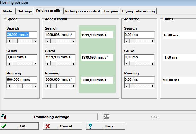
24 Application Note (EN) Page 24 of 29 9 Homing The setup for homing position of the axis will be done in the homing position window: - homing methods - homing-offset - speed and acceleration during homing _EN_ _servoTEC_S2_Drive_via_digital_inputs_and_outpus_R1a
 please also change the direction of the limit switches (change limit switch).")
25 Application Note (EN) Page 25 of Setup for limit switch IEF-Werner GmbH usually installs limit switches as normally open contact. The negative limit switch is to find on the motor side. If the axis direction has to be changed (different mechanical direction) please also change the direction of the limit switches (change limit switch). _EN_ _servoTEC_S2_Drive_via_digital_inputs_and_outpus_R1a

26 Application Note (EN) Page 26 of Jogging mode For the function "Jogging-mode" there are two data sets stored in the window "destination parameters". - Jogging mode right: TIPP 0 (pos) and - Jogging mode left: TIPP 1 (neg) _EN_ _servoTEC_S2_Drive_via_digital_inputs_and_outpus_R1a
27 Application Note (EN) Page 27 of Parameterize destinations With the Servo Positioning Controller servotec S2 it is possible to set more than 256 destinations. Using this application 5021 as an example it is possible to choose up to 4 destinations via digital inputs DIN0 and DIN1. If more than 4 destinations are needed the function can be changed of existing inputs or extending the digital inputs (technology module). For each destination there are a lot of parameters for optimal adjustment to the function of the machine: Positioning: relative, absolute Messages: Destination position: Acceleration, braking acceleration Follow-on position: _EN_ _servoTEC_S2_Drive_via_digital_inputs_and_outpus_R1a


28 Application Note (EN) Page 28 of Destination position 0 - Positioning: absolute - Destination position: 10,00 mm - Speed: 200mm/s - Acceleration: 2000mm/s2 - Breaking acceleration: 2000mm/s2 - Following position: 0 _EN_ _servoTEC_S2_Drive_via_digital_inputs_and_outpus_R1a


29 Application Note (EN) Page 29 of Destination position 1 - Positioning: absolute - Destination position: 100,00 mm - Speed: 350mm/s - Acceleration: 1500mm/s2 - Breaking acceleration: 500mm/s2 - Following position: 0 _EN_ _servoTEC_S2_Drive_via_digital_inputs_and_outpus_R1a
Application note "Wiring LV-servoTEC S2
 Application note "Wiring LV-servoTEC S2 Short version: In this application document, the user is given information regarding proper wiring specifically regarding the: EMERGENCY OFF function with protective
Manual. Decentralized Extra-Low Voltage Servo Drive CMP ELVCD Functional Safety * _0717*
 Drive Technology \ Drive Automation \ System Integration \ Services *23494050_0717* Manual Decentralized Extra-Low Voltage Servo Drive CMP ELVCD Functional Safety Edition 07/2017 23494050/EN SEW-EURODRIVE
CMMT-AS-PN controlled by SINAPOS functions block with Siemens S controller
 Application Note CMMT-AS-PN controlled by SINAPOS functions block with Siemens S7 1500 controller This document describes which control figures are implemented in CMMT-AS-PN drives and how to use it in
Drive Technology \ Drive Automation \ System Integration \ Services. Manual. CCU Universal Module Application Module
 Drive Technology \ Drive Automation \ System Integration \ Services Manual CCU Universal Module Application Module Edition 05/2011 17061210 / EN SEW-EURODRIVE Driving the world Contents Contents 1 General
SERIES EGRR M1095 MOTOR SYSTEM TIPS AND PRACTICES
 SERIES EGRR M1095 MOTOR SYSTEM TIPS AND PRACTICES PHD, Inc. makes no warranty as to the fitness of its products for a specific application. In no event shall PHD, Inc. be liable for loss of profits, indirect,
LabVIEW -VI MCC. Virtual Instruments for MCC Control Units. Manual 1253-A001 GB
 LabVIEW -VI MCC Virtual Instruments for MCC Control Units Manual 1253-A001 GB phytron LabVIEW Virtual Instruments for MCC Control Units TRANSLATION OF THE GERMAN ORIGINAL MANUAL 6/2010 Manual MA 1253-A001
Product Demo Instructions. MP2600iec Demo Instructions: v03. Applicable Product: MP2600iec with MotionWorks IEC Pro
 Product Demo Instructions MP2600iec Demo Instructions: v03 Applicable Product: MP2600iec with MotionWorks IEC Pro Yaskawa Electric America 2121 Norman Drive South Waukegan, IL 60085 1-800-927-5292 Page
MSD Servo Drive. Specification ma Inputs on Control Card. Description of Basic Functionality
 Specification 4 20 ma Inputs on Control Card Description of Basic Functionality moog 4.. 20mA Inputs on Control Card 2. Technical alterations reserved MSD 4 20 ma Inputs on control card Id no.: CB57187-001,
Keypad Lay-out. Copyright 2008 Optimal Engineering Systems, Inc
 Keypad Lay-out - 1 - Setting Acceleration Pressing the for each motor. key allows the user to enter the acceleration values 1) Press. 2) The controller displays Select Axis:1 thru 3. 3) Press 1 for X axis,
Conveyor System Utilizing Safety Observation Function
 Conveyor System Utilizing Safety Observation Function [System Configuration] GOT Q06UDEHCPU Q172DSCPU QY40P Q173DSXY Axis 1 Axis 2 No.2 Conveyor axis No.1 Conveyor axis [Mitsubishi solution] Motion CPU:
Manual. NC PTP: Quick Starting Guide. TwinCAT 3. Version: Date: Order No.: TF5000
 Manual NC PTP: Quick Starting Guide TwinCAT 3 Version: Date: Order No.: 1.1 2018-01-26 TF5000 Contents Contents 1 Foreword... 5 1.1 Notes on the documentation... 5 1.2 Safety instructions... 6 2 TF5000
S7-300 Programmable Controller
 S7-300 Programmable Controller This description belongs to the following documentation packages with the order numbers given: S7 300 Programmable Controller 6ES7 398 8AA02 8BA0 ET 200M Distributed I/O
SIMATIC/SINAMICS. Getting started with SINAMICS V90 PN on S Motion Control. Fundamental safety instructions 1. Introduction
 Fundamental safety instructions 1 Introduction 2 SIMATIC/SINAMICS Getting started with SINAMICS V90 PN on S7-1500 Motion Control Getting Started Prepare the configuration 3 Create a project 4 Creating
Hydraulic Axis with SIMOTION D410 (Use of the Onboard Encoder Interface without Power Unit PM340)
") Hydraulic Axis with SIMOTION D410 (Use of the Onboard Encoder Interface without Power Unit PM340) General Information Project subject to technical modifications. Copyright Passing on and reproduction of
Hydraulic Axis with SIMOTION D410 (Use of the Onboard Encoder Interface without Power Unit PM340) General Information Project subject to technical modifications. Copyright Passing on and reproduction of
3 CU240E-2 6SL3244-0BB12-1BA1 3 CU240E-2 DP 6SL3244-0BB12-1PA1. RS485/USS 6 3 (opt. per 2 DI) 3 CU240E-2 F 6SL3244-0BB13-1BA1
 3 CU240E-2 F 6SL3244-0BB13-1BA1") Control Units CU240B-2, CU240E-2 Overview Safety Integrated functions The basic version of the CU240E-2 series (CU240E-2 and CU240E-2 DP) includes the safety function Safe Torque Off (STO) (certified according
Control Units CU240B-2, CU240E-2 Overview Safety Integrated functions The basic version of the CU240E-2 series (CU240E-2 and CU240E-2 DP) includes the safety function Safe Torque Off (STO) (certified according
Commissioning the 9400 Highline TA CiA402 with EtherCAT and Beckhoff NC
 Commissioning the 9400 Highline TA CiA402 with EtherCAT and Beckhoff NC Contents 1. Preface/aim of the Application Report...2 2. Introduction...3 2.1. General information on EtherCAT...3 2.2. General information
S Motion Control V12 SP1 SIMATIC. STEP 7 S Motion Control V12 SP1. Preface. Using S Motion Control. S Motion Control 2
 Preface Using S7-1200 Motion Control 1 SIMATIC S7-1200 Motion Control 2 STEP 7 Function Manual 08/2013 A5E03790551-02 Legal information Warning notice system This manual contains notices you have to observe
Motion Tool Schunk (MTS) for electronical 'Pick and Place' unit PPU-E
 for electronical 'Pick and Place' unit PPU-E") Translation of the original manual Motion Tool Schunk (MTS) for electronical 'Pick and Place' unit PPU-E Software Manual 01.01/MTS- PPU-E/en Imprint: Copyright: This manual remains the copyrighted property
Translation of the original manual Motion Tool Schunk (MTS) for electronical 'Pick and Place' unit PPU-E Software Manual 01.01/MTS- PPU-E/en Imprint: Copyright: This manual remains the copyrighted property
Indra Works DS Tuning Procedure
 Indra Works DS Tuning Procedure Rexroth Indramat drives can be tuned in-house or in the field. The following procedures are written for a technician tuning a drive, in-house. Where an asterisk (*) appears,
JetMove 2xx. Version update from V to V We automate your success.
 Version update from V. 2.15 to V. 2.16 We automate your success. Introduction Revision 1.01 August 2017 / Printed in Germany This document has been compiled by Jetter AG with due diligence, and based on
SIMATIC FM 453. Getting Started. 04/2007 Edition. First Steps in Commissioning. Siemens
 SIMATIC FM 453 Getting Started 04/2007 Edition First Steps in Commissioning This Guide uses a specific example for channel 1 (axis 1) with servo drive or step drive with four operational steps in successive
TOX -ElectricDrive. Electrical drive technology with press forces from kn
 TOX -ElectricDrive Electrical drive technology with press forces from 2 1000 kn 1 The electromechanical servo drive When working processes require flexibility and precision, electromechanical servo drives
Motor controller SFC-DC
 Motor controller SFC-DC Brief overview SFC-DC-...-IO SFC-DC-...-PB SFC-DC-...-CO SFC-DC-...-DN English 8081484 2018-01f [8081486] Translation of the original instructions Documentation on the product For
Courtesy of CMA/Flodyne/Hydradyne Motion Control Hydraulic Pneumatic Electrical Mechanical (800)
") Servo Drives The wide product range of LinMot servo drives allows the rapid implementation in applications from simple two position point to point movements up to complex, high-precision multi-axis synchronization
Servo Drives The wide product range of LinMot servo drives allows the rapid implementation in applications from simple two position point to point movements up to complex, high-precision multi-axis synchronization
SIMATIC Easy Motion Control. Getting Started Edition 02/2003. First Steps in Commissioning
 SIMATIC Edition 02/2003 First Steps in Commissioning Safety Guidelines This manual contains notices intended to ensure personal safety, as well as to protect the products and connected equipment against
How to setup Travel to fixed stop with CMMT-AS-PN by using the SINA_POS / telegram 111
 Application Note How to setup Travel to fixed stop with CMMT-AS-PN by using the SINA_POS / telegram 111 This document describes how to set up the CMMT-AS-...-PN in "trav-el to fixed stop" mode by using
INTERFACE. User Manual
 INTERFACE User Manual UM EN PSR-CONF-WIN Order No.: 2888107 PSR Configuration Software INTERFACE User Manual PSR Configuration Software 09/2005 Designation: Revision: Order No.: UM EN PSR-CONF-WIN 00
Configuring Logosol CNC page 2. Setting up the machine limits and user units page 3. Setting up the Motion parameters page 4. I/O mapping page 7
 Configuring Logosol CNC page 2 Setting up the machine limits and user units page 3 Setting up the Motion parameters page 4 I/O mapping page 7 I/O setup page 9 Tools control page 11 Tool Life management
User s Manual V MillPlus IT. NC Software
 User s Manual V600-02 MillPlus IT NC Software 538 952-02 538 953-02 538 954-02 538 955-02 538 956-02 English (en) 6/2008 Controls on the visual display unit Select window User keys Manual operation Axis-direction
Everything s possible. Modbus Communication. Reference Manual. DigiFlex Performance Servo Drives. MNCMMBRF-02
 Everything s possible. Modbus Communication Reference Manual DigiFlex Performance Servo Drives www.a-m-c.com MNCMMBRF-02 Preface ADVANCED Motion Controls constantly strives to improve all of its products.
Drive Technology \ Drive Automation \ System Integration \ Services. Manual. Control Cabinet Inverter MOVITRAC B Functional Safety
 Drive Technology \ Drive Automation \ System Integration \ Services Manual Control Cabinet Inverter MOVITRAC B Functional Safety Edition 05/2009 16811216 / EN SEW-EURODRIVE Driving the world Content Content
Applications & Tools. Control of the Safety Integrated Extended Functions of the SINAMICS S110 via the fail-safe inputs of the CU305 SINAMICS S110
 Cover sheet Control of the Extended Functions of the SINAMICS S110 via the fail-safe inputs of the CU305 SINAMICS S110 Application example November 2011 Applications & Tools Answers for industry. Industry
Application Note: Wiring Diagrams to replace DS2000 with DS2020
 Application Note: Wiring Diagrams to replace DS2000 with DS2020 L-ANS1-E-171 Foreword Moog has identified the DS2020 as the ideal replacement for the DS2000 drive in all applications. In the following
NCT. PLC Programmer s Manual. Machine Tool Controls. From SW Version x.061 (M) (L)
 (L)") NCT Machine Tool Controls PLC Programmer s Manual From SW Version x.061 (M) (L) Produced and developed by NCT Automation kft. H1148 Budapest Fogarasi út 7 : Letters: 1631 Bp. P.O. Box 26 F Phone: (+36
NCT Machine Tool Controls PLC Programmer s Manual From SW Version x.061 (M) (L) Produced and developed by NCT Automation kft. H1148 Budapest Fogarasi út 7 : Letters: 1631 Bp. P.O. Box 26 F Phone: (+36
Configuration of CMMT-AS- -EC/PN to run 3rd party motor
 Application Note Configuration of CMMT-AS- -EC/PN to run 3rd party motor This document describes how to configure and run 3 rd party motors in combination with CMMT-AS-..-EC/PN drive. CMMT-AS- -EC CMMT-AS-
SIMPLY PRECISE USER MANUAL. ADJUSTMENT TOOL For NUMERIK JENA Encoders with Online Compensation
 USER MANUAL ADJUSTMENT TOOL For NUMERIK JENA Encoders with Online Compensation 2 Index 1. Features and Applications... 3 1.1 Functions of the ADJUSTMENT TOOL... 3 1.2 Dynamic Offset and Amplitude Control
New functionalities for LXM05 AC Servo drive Extension to product manual V1.00,
 New functionalities for LXM5 AC Servo drive Extension to product manual V1., 8.28 www.schneiderelectric.com Important information New functionalities for LXM5 Important information The new functionalities
E/A CAN. I /O Module for CAN Networks. Product Manual E-V0305.doc
 E/A CAN I /O Module for CAN Networks Product Manual 07-04-04-E-V0305.doc Additional Supporting Documentation UL: 04-02-03 Absolute encoder with CAN UL: 07-01-05-06 635 - Product - Manual UL: 07-01-08-02
Drive Technology \ Drive Automation \ System Integration \ Services. Manual. MOVITRAC MC07B Functional Safety
 Drive Technology \ Drive Automation \ System Integration \ Services Manual MOVITRAC MC07B Functional Safety Edition 12/2011 19396414 / EN SEW-EURODRIVE Driving the world Contents Contents 1 General Information...
Micro800 Programmable Controllers: Getting Started with Motion Control Using a Simulated Axis
 Quick Start Micro800 Programmable Controllers: Getting Started with Motion Control Using a Simulated Axis Catalog Numbers Bulletin 2080-LC30, 2080-LC50 Important User Information Solid-state equipment
C3 I20 I32 T11 ControlManager FB45
 CONTROL TECHNOLOGY FROM PARKER C3 I20 I32 T11 ControlManager FB45 A1039 Version: 39 Warranty Disclaimer While efforts were made to verify the accuracy of the information contained in this documentation,
Applications & Tools. Calculation examples for safety functions according to EN ISO SINUMERIK 840D sl
 lcover sheet Calculation examples for safety functions according to EN ISO 13849 SINUMERIK 840D sl Calculation examples for safety functions at horizontal axes October 2013 Applications & Tools Answers
Application Note I-Port event/error list
 Application Note I-Port event/error list A list of events and errors are transmitted via I-Port -ST-...LKP 100163 Title... I-Port event/error list Version... 1.10 Document no.... 100163 Original...en Author...
SIMOCRANE CeSAR standalone STS, GSU Version 2.1 SP1 HF1
 SIMOCRANE CeSAR standalone STS, GSU Version 2.1 SP1 HF1 These notes take precedence over information in other documents. Please read the notes through carefully because they contain information that it
Drive Technology \ Drive Automation \ System Integration \ Services. Manual. Electronic Motor DRC Functional Safety
 Drive Technology \ Drive Automation \ System Integration \ Services Manual Electronic Motor DRC Functional Safety Edition 02/2012 19376812 / EN SEW-EURODRIVE Driving the world Contents Contents 1 General
Motion Control Products Application note Implementing safety functions on ABB servo drives
 Motion Control Products Application note Implementing safety functions on ABB servo drives AN00206-006 Introduction The purpose of this application note is to provide a guide to machine builders on functional
Drive Technology \ Drive Automation \ System Integration \ Services. Manual. MOVITRAC MC07B Functional Safety
 Drive Technology \ Drive Automation \ System Integration \ Services Manual MOVITRAC Functional Safety Edition 12/2011 19396414 / EN SEW-EURODRIVE Driving the world Contents Contents 1 General Information...
PLC Lib: Tc3_MC2_AdvancedHoming
 Manual PLC Lib: Tc3_MC2_AdvancedHoming TwinCAT 3 Version: Date: 1.2 2017-05-03 Table of contents Table of contents 1 Foreword... 5 1.1 Notes on the documentation... 5 1.2 Safety instructions... 6 2 Overview...
9400 with SM100 Safe stop 1 with BBH SMX 11 (architecture according to performance level e of EN ISO )
") 9400 with SM00 Safe stop with BBH SMX (architecture according to performance level e of EN ISO 849-) Connection diagram (section): 4VDC DI E94AxHExxxx X5 Start Not-Halt/ Emergency stop 4 X4 X4 X X X X
9400 with SM00 Safe stop with BBH SMX (architecture according to performance level e of EN ISO 849-) Connection diagram (section): 4VDC DI E94AxHExxxx X5 Start Not-Halt/ Emergency stop 4 X4 X4 X X X X
SD17098IX Specifications Networked Stepper Driver & Indexer Revision 0.0
 The SD17098IX is a 170V 9.8amp stepper driver and indexer combination that communicates on a Network. The available networks, along with the corresponding AMCI part numbers, are shown in the following
Virtual Instruments for the phymotion TM Controller
 LabVIEW -VI phymotion TM Virtual Instruments for the phymotion TM Controller MANUAL 1301-A001 EN Extreme. Precision. Positioning. phytron LabVIEW Virtual Instruments for the phymotion TM Controller TRANSLATION
SMVector Additional I/O Module Installation and Operation Manual
 SMVector Additional I/O Module Installation and Operation Manual About These Instructions This documentation applies to the optional Additional I/O module for the SMVector inverter and should be used in
Controller CMXH-ST2 Key features
 Key features At a glance The controller controls two servo motors which drive an H-shaped rotating toothed belt. The toothed belt moves a slide, whose position is calculated by the controller from the
MRZJW3- SETUP154E. General-Purpose AC Servo Servo Configuration Software MODEL INSTALLATION GUIDE
 General-Purpose AC Servo Servo Configuration Software MODEL MRZJW3- SETUP154E INSTALLATION GUIDE Thank you for choosing the Mitsubishi general-purpose AC servo Servo Configuration Software. To optimize
Completely Integrated the Intelligent Compact Drives IclA
 Completely Integrated the Intelligent Compact Drives IclA Berger Lahr offers you the positioning and automation solutions you need, based on our tried and proven series of products. Our comprehensive engineering
Q9 ASD LOW VOLTAGE DRIVE
 ASD LOW VOLTAGE DRIVE HVAC-MINDED, SYSTEM FRIENDLY RELIABLE Toshiba has manufactured pulse-width modulated drives since 1981 and is one of the few companies that manufactures both motors and drives in
Version Accurate Technology, Inc.
 Single Axis Position Control Unit (PCU) User s Manual Version 2.040 270 Rutledge Rd. Suite E Fletcher, North Carolina 28732 USA 828-654-7920 www.proscale.com The contents of this document are protected
User Manual. NanoCAN. Application for stepper motor controls and Plug & Drive motors (version V )
") User Manual Application for stepper motor controls and Plug & Drive motors (version V2.0.0.1) NANOTEC ELECTRONIC GmbH & Co. KG Kapellenstraße 6 D-85622 Feldkirchen b. Munich, Germany Tel. +49 (0)89-900
User Manual Application for stepper motor controls and Plug & Drive motors (version V2.0.0.1) NANOTEC ELECTRONIC GmbH & Co. KG Kapellenstraße 6 D-85622 Feldkirchen b. Munich, Germany Tel. +49 (0)89-900
SERVOSTAR 400 (S400) Quickstart Guide. Version
 Quickstart Guide. Version") SERVOSTAR 400 (S400) Quickstart Guide Version 12.2014 Keep all manuals as a product component during the life span of the product. Pass all manuals to future users/owners of the product. Preparation The
SERVOSTAR 400 (S400) Quickstart Guide Version 12.2014 Keep all manuals as a product component during the life span of the product. Pass all manuals to future users/owners of the product. Preparation The
CANopen Reference Manual
 Reference Manual Stepper Motor Positioning Controls and Plug & Drive Motors NANOTEC ELECTRONIC GmbH & Co. KG Gewerbestraße 11 D-85652 Landsham near Munich, Germany Tel. +49 (0)89-900 686-0 Fax +49 (0)89-900
Safety module SY6 Manual
 Safety module SY6 Manual stober.com en-us 06/2017 ID 442744.01 Table of contents STOBER Table of contents 1 Foreword... 5 2 User information... 6 2.1 Storage and transfer... 6 2.2 Described product type...
Manual. Global Drive. PLC Developer Studio. Global Drive. LenzeIOSystem.lib. Function library
 L Manual Global Drive PLC Developer Studio Global Drive Function library LenzeIOSystem.lib The LenzeIOSystem.lib and LenzeIOSystemVxxxx.lib function libraries can be used for the following Lenze PLC devices:
Epsilon EP. Compact and Economical. 16 Amp Drive. RoHS approved option! Position Tracker. Epsilon EP.
 Compact and Economical The Series is the most compact digital servo drive in the Control Techniques lineup. Designed to fit in cabinets as small as six inches (152 mm) deep, with cables attached. The drives
Manual. MOVIAXIS MX Multi-Axis Servo Inverter Virtual Encoder Technology Function. Edition 05/ / EN
 Gearmotors \ Industrial Gear Units \ Drive Electronics \ Drive Automation \ Services MOVIAXIS MX Multi-Axis Servo Inverter Virtual Encoder Technology Function Edition 05/2007 11576626 / EN Manual SEW-EURODRIVE
SIEB & MEYER W. Drive System SD2. Device control P-TD
 SIEB & MEYER W Drive System SD2 Device control P-TD-0000377.1 2014-07-16 W Copyright Copyright 2014 SIEB & MEYER AG. All rights reserved. This manual or extracts thereof may only be copied with the explicit
Servo press kit YJKP - Host interface
 Application Note Servo press kit YJKP - Host interface Host interface of the servo press kit YJKP: - Communication possibilities - Workflow - Object directory - Communication protocol - Communication Mobus
DMX V Interface. User Manual
 DMX-0...10V Interface User Manual DMX-0..10V Interface 2 Description The 0-10V Interface is excellent suitable for triggering electronic devices with 0-10V or 1-10V control input. At the output 8 analog
IPEmotion M.A.L.- PlugIn IPETRONIK CAN
 IPEmotion M.A.L.- PlugIn IPETRONIK CAN User manual March 2009 All rights reserved! Content Content Content...2 1 Important information...4 1.1 Liability, Warranty, Copyright, License agreement... 4 1.1.1
Quickstart Strategies for Commissioning and Optimization AX2000
 Quickstart Strategies for Commissioning and Optimization AX2000 Edition 06/00 Previous editions Edition Comments 06 / 00 First edition VGA is a registered trademark of International Business Machines Corp.
Rexroth IndraMotion MTX Diagnosis Messages
 Industrial Hydraulics Electric Drives and Controls Linear Motion and Assembly Technologies Pneumatics Service Automation Mobile Hydraulics Rexroth IndraControl VCP 20 Rexroth IndraMotion MTX Diagnosis
FANUC HMIs IMPORTANT PRODUCT INFORMATION. General Description READ THIS INFORMATION FIRST. High Performance. Easy to Use
 Restarts for autonumbers that do not restart in each chapter. figure bi level 1, reset table_big level 1, reset chap_big level 1, reset app_big level 1, reset figure_ap level 1, reset table_ap level 1,
ProTool DriveLine. Software User manual 375/16
 ProTool DriveLine Software User manual 375/16 Table of contents 1 General Information... 3 1.1 Documentation...3 1.2 Disclaimer...3 1.3 Trademarks...3 1.4 System requirements...3 2 About ProTool DriveLine...
Registration Moves with Kollmorgen AKD Motion Tasking Drive
 Registration Moves with Kollmorgen AKD Motion Tasking Drive Overview Often it is desirable in an application to move a set distance after seeing a mark via photo eye and a mark on material that travels
KOLLMORGEN. SERVOSTAR CD. SERCOS IDN Manual M-SS rev. F. Solutions by D A N A H E R M O T I O N
 KOLLMORGEN www.danahermotion.com SERVOSTAR CD Solutions by D A N A H E R M O T I O N SERCOS IDN Manual M-SS-017-05 rev. F Revision History Revision Edition Date Reason for Revision 1 05/01/1999 Initial
Simple Motion Control Connected Components Building Block. Quick Start
 Simple Motion Control Connected Components Building Block Quick Start Important User Information Solid state equipment has operational characteristics differing from those of electromechanical equipment.
GuardLogix Controller to Kinetix 6000 Drive with Safe-Off using EtherNet/IP CompactBlock Guard I/O Module
 Safety Application Example GuardLogix Controller to Kinetix 6000 Drive with Safe-Off using EtherNet/IP CompactBlock Guard I/O Module Safety Rating: SIL3/Category 3 (also see SIL3/CAT4 section), according
TB267 (Rev4) - CNC11 Yaskawa Sigma5 Precision Mode Setup
 - CNC11 Yaskawa Sigma5 Precision Mode Setup") TB267 (Rev4) - CNC11 Yaskawa Sigma5 Precision Mode Setup Overview: This document will walk you through the process of configurating and tuning a Yaskawa Sigma V Servo Drive Pack and motor with a centroid
TB267 (Rev4) - CNC11 Yaskawa Sigma5 Precision Mode Setup Overview: This document will walk you through the process of configurating and tuning a Yaskawa Sigma V Servo Drive Pack and motor with a centroid
Technical data. General specifications. Linearity error ± 0.1 Functional safety related parameters MTTF d 480 a at 40 C Mission Time (T M ) L 10
 L 10") Model Number Features Very small housing Up to 31 bit overall resolution CANopen interface Free of wear magnetic sampling High resolution and accuracy Description This absolute rotary encoder provides
Model Number Features Very small housing Up to 31 bit overall resolution CANopen interface Free of wear magnetic sampling High resolution and accuracy Description This absolute rotary encoder provides
Data setting software MEXE02 DGⅡSeries / EAS Series
 HL-14056 Data setting software MEXE02 DGⅡSeries / EAS Series OPERATING MANUAL Thank you for purchasing an Oriental Motor product. This operating manual describes product handling procedures and safety
Documentation for. AX TwinSAFE Drive Option. TwinSAFE Drive Option for AX8xxx-x1xx Servo Drives. Version: Date: 1.0.
 Documentation for AX8911 - TwinSAFE Drive Option TwinSAFE Drive Option for AX8xxx-x1xx Servo Drives Version: Date: 1.0.0 2017-10-26 Table of contents Table of contents 1 Foreword... 5 1.1 Notes on the
A1 A2 A3 A4 A5 A6 A7 A8 A9 A10 A11 A12 A13 A14 A15 A16 Controls:
 Product name: Switching actuator 16fold / blind/shutter actuator 8fold Design: DIN rail mounting device Item no.: 1029 00 ETS search path: Gira Giersiepen / output / Binary output mix / switching act.
X-CAM A10-3H 3 Axis Gimbal for GOPRO. User Manual ( V2.00 )
") X-CAM A10-3H 3 Axis Gimbal for GOPRO User Manual ( V2.00 ) The X-CAM A10-3H 3 Axis Gimbal has been setup and calibrated for use with GOPRO cameras, it is ready to use straight from the box. Specifications:
X-CAM A10-3H 3 Axis Gimbal for GOPRO User Manual ( V2.00 ) The X-CAM A10-3H 3 Axis Gimbal has been setup and calibrated for use with GOPRO cameras, it is ready to use straight from the box. Specifications:
VARAN-INTERFACE VAC 012
 VARAN-INTERFACE VAC 012 This VARAN interface module is used for communication between a DIAS drive and a control over the VARAN bus. The VAC 012 is built into the DIAS-Drive and is also equipped with interface
Drive Technology \ Drive Automation \ System Integration \ Services. MPLCTec.._MX Libraries. Manual. Edition 04/ / EN
 Drive Technology \ Drive Automation \ System Integration \ Services MPLCTec.._MX Libraries Edition 4/8 1663419 / EN Manual SEW-EURODRIVE Driving the world Contents 1 General Notes... 4 1.1 Structure of
First Steps in Commissioning CPU. 31xC: Positioning with digital output SIMATIC
 First Steps in Commissioning CPU 31xC: Positioning with digital output Introduction 1 Preparation 2 SIMATIC S7-300 First Steps in Commissioning CPU 31xC: Positioning with digital output Learning units
SINUMERIK 840D sl - OEM. Kinematic Transformation Configuration Questions. Preface. Transformation Questions. Appendix. Configuration Manual 10/2008
 Preface SINUMERIK 840D sl - OEM Transformation Questions Appendix 1 A Kinematic Transformation Configuration Questions Configuration Manual Valid for Control SINUMERIK 840D sl SINUMERIK 840DE sl (export
Manual 5 Axis CNC Interface Breakout Board Model#-DB25-1R5AM
 Manual 5 Axis CNC Interface Breakout Board Read this manual carefully before making connections to the board. Store this manual away for further reference. Safety Notes: The electronics of the control
Power, Control & Green Solutions. Agile. Application manual Functional Safety. T +31(0) F +31(0) E elsto.
 F +31(0) E elsto.") Power, Control & Green Solutions Agile Application manual Functional Safety T +31(0)88 7865800 F +31(0)88 7865899 E info@elsto.eu elsto.eu General Information about the Documentation For the series of
Power, Control & Green Solutions Agile Application manual Functional Safety T +31(0)88 7865800 F +31(0)88 7865899 E info@elsto.eu elsto.eu General Information about the Documentation For the series of
RoboClaw 2x30A Dual Channel Motor Controller
 RoboClaw 2x30A, 34VDC Dual Channel Brushed DC Motor Controller Version 2.2 (c) 2016 Ion Motion Control. All Rights Reserved. Feature Overview: 60 Amps Peak Per Channel Channel Bridging Supported Dual Quadrature
EtherNet/IP with Applied Motion Drives
 EtherNet/IP with Applied Motion Drives EtherNet/IP with Applied Motion Drives Jeff Kordik CTO Applied Motion Products, Inc. 1 92-5 Rev. B Applied Motion Products Contents Overview of EtherNet/IP...3 EtherNet/IP
Miniature circuit-breaker versus electronic selectivity module Selective monitoring of 24 V DC load circuits
 Miniature circuit-breaker versus electronic selectivity module Selective monitoring of 24 V DC load circuits In modern plant and machine construction all 24 V DC loads whether rugged electro-mechanical
AG05. Actuator with CANopen interface User manual 055/18
 AG05 Actuator with CANopen interface User manual 055/18 Table of contents 1 General Information... 6 1.1 Documentation...6 2 Block Diagram... 6 3 Display and Control Keys... 7 3.1 General...7 3.2 LCD display...7
PROFINET USER S GUIDE ACSI Servo
 PROFINET USER S GUIDE ACSI Servo 3600-4196_05 Tolomatic reserves the right to change the design or operation of the equipment described herein and any associated motion products without notice. Information
HARDWARE MANUAL TMCM-1613 TMCM-1613-REC. Hardware Version V TRINAMIC Motion Control GmbH & Co. KG Hamburg, Germany.
 MODULES FOR BLDC MOTORS MODULES Hardware Version V 1.10 HARDWARE MANUAL + + TMCM-1613 + + Single Axis BLDC Controller / Driver Block-commutation Hall-sensor based Analog+digital inputs / outputs Up-to
Standard User Interface StdHMI for CNC Controllers (W2000, XP)
") E CONTROL Standard User Interface StdHMI for CNC Controllers (W2000, XP) Operating Instructions eckelmann.de MANAGING BOARD: DR.-ING. GERD ECKELMANN, CHAIRMAN DR.-ING. PETER CORDES, DR.-ING. FRANK-THOMAS
E CONTROL Standard User Interface StdHMI for CNC Controllers (W2000, XP) Operating Instructions eckelmann.de MANAGING BOARD: DR.-ING. GERD ECKELMANN, CHAIRMAN DR.-ING. PETER CORDES, DR.-ING. FRANK-THOMAS
Home the Tool Changer
 PLEASE NOTE: This document applies to several different types of KOMO tool changers, but may not include all of them. Be sure to scroll down to see if the one you are looking for is included. If you are
Modbus User Manual APPLIED MOTION PRODUCTS, INC. Modbus is a registered trademark of Schneider Electric, licensed to the Modbus Organization, Inc.
 APPLIED MOTION PRODUCTS, INC. Modbus is a registered trademark of Schneider Electric, licensed to the Modbus Organization, Inc. Covers the following Modbus RTU enabled drives: ST5-Q-RN ST5-Q-RE ST5-Q-NN
Interpreter. SIMOTION Interpreter. Preface 1. Structure of a command 2. Commands for program control of the Interpreter 3. Motion control commands 4
 Preface 1 Structure of a command 2 Commands for program control of the 3 SIMOTION Parameter Manual Motion control commands 4 Commands for transition conditions 5 Commands for program branches 6 Other commands
USB Indexer USB Indexer for CNC Controls
 USB Indexer USB Indexer for CNC Controls 2009-2011 Calmotion LLC, All rights reserved Calmotion LLC 9909 Topanga Canyon Blvd. #322 Chatsworth, CA 91311 www.calmotion.com -1 2009-2011Calmotion LLC, All
MELDASMAGIC MMI OPERATION MANUAL (FOR L/G) BNP-B2194 (ENG)
 BNP-B2194 (ENG)") MELDASMAGIC MMI OPERATION MANUAL (FOR L/G) BNP-B2194 (ENG) MELDASMAGIC is a registered trademark of Mitsubishi Electric Corporation. Microsoft and Windows are registered trademarks of Microsoft Corporation.
MELDASMAGIC MMI OPERATION MANUAL (FOR L/G) BNP-B2194 (ENG) MELDASMAGIC is a registered trademark of Mitsubishi Electric Corporation. Microsoft and Windows are registered trademarks of Microsoft Corporation.