RSC-4BT Rackmount Storage Chassis User's Manual
|
|
|
- Janel Stevenson
- 6 years ago
- Views:
Transcription

1 RSC-4BT Rackmount Storage Chassis User's Manual UM_RSC-4BT_Final_080415
2 CONTENTS PREFACE... i SAFETY INSTRUCTIONS... ii Chapter 1. Prodcut Introduction Box Content Specifications General Information...3 Chapter 2. Hardware Installation Removing and Installing Top Cover Installing/ Removing a Hard Disk Drive Removing and Installing a PSU Module Removing and Installing a Fan Module Removing and Installing the HDD backplane Module Tool-less Blade Slide Installation Instruction...14 Chapter 3. Hardware Introduction HARDWARE DESIGN SPECIFICATION...21 Chapter 4. HDD Blackplane Introduction Expender firmware update through phone connector port Update the expander firmware through in-band G expander EDFB setting Slot HDD power setting HDD BP thermal sensor temperature setting...52 Chapter 5. Technical Support contents
3 Copyright 2015 AIC, Inc. All Rights Reserved. This document contains proprietary information about AIC products and is not to be disclosed or used except in accordance with applicable agreements.
4 PREFACE Copyright No part of this publication may be reproduced, stored in a retrieval system, or transmitted in any form or by any means, electronic, mechanical, photostatic, recording or otherwise, without the prior written consent of the manufacturer. Trademarks All products and trade names used in this document are trademarks or registered trademarks of their respective holders. Changes The material in this document is for information purposes only and is subject to change without notice. Warning 1. A shielded-type power cord is required in order to meet FCC emission limits and also to prevent interference to the nearby radio and television reception. It is essential that only the supplied power cord be used. 2. Use only shielded cables to connect I/O devices to this equipment. 3. You are cautioned that changes or modifications not expressly approved by the party responsible for compliance could void your authority to operate the equipment. Disclaimer AIC shall not be liable for technical or editorial errors or omissions contained herein. The information provided is provided "as is" without warranty of any kind. To the extent permitted by law, neither AIC or its affiliates, subcontractors or suppliers will be liable for incidental, special or consequential damages including downtime cost; lost profits; damages relating to the procurement of substitute products or services; or damages for loss of data, or software restoration. The information in this document is subject to change without notice. i
5 SAFETY INSTRUCTIONS Before getting started, please read the following important cautions: All cautions and warnings on the equipment or in the manuals should be noted. Most electronic components are sensitive to electrical static discharge. Therefore, be sure to ground yourself at all times when installing the internal components. Use a grounding wrist strap and place all electronic components in static-shielded devices. Grounding wrist straps can be purchased in any electronic supply store. Be sure to turn off the power and then disconnect the power cords from your system before performing any installation or servicing. A sudden surge of power could damage sensitive electronic components. Do not open the system s top cover. If opening the cover for maintenance is a must, only a trained technician should do so. Integrated circuits on computer boards are sensitive to static electricity. Before handling a board or integrated circuit, touch an unpainted portion of the system unit chassis for a few seconds. This will help to discharge any static electricity on your body. Place this equipment on a stable surface when install. A drop or fall could cause injury. Please keep this equipment away from humidity. Carefully mount the equipment into the rack, in such manner, that it won t be hazardous due to uneven mechanical loading. This equipment is to be installed for operation in an environment with maximum ambient temperature below 35 C. The openings on the enclosure are for air convection to protect the equipment from overheating. DO NOT COVER THE OPENINGS. Never pour any liquid into ventilation openings. This could cause fire or electrical shock. Make sure the voltage of the power source is within the specification on the label when connecting the equipment to the power outlet. The current load and output power of loads shall be within the specification. This equipment must be connected to reliable grounding before using. Pay special attention to power supplied other than direct connections, e.g. using of power strips. Place the power cord out of the way of foot traffic. Do not place anything over the power cord. The power cord must be rated for the ii
6 product, voltage and current marked on the product s electrical ratings label. The voltage and current rating of the cord should be greater than the voltage and current rating marked on the product. If the equipment is not used for a long time, disconnect the equipment from mains to avoid being damaged by transient over-voltage. Never open the equipment. For safety reasons, only qualified service personnel should open the equipment. If one of the following situations arise, the equipment should be checked by service personnel: 1. The power cord or plug is damaged. 2. Liquid has penetrated the equipment. 3. The equipment has been exposed to moisture. 4. The equipment does not work well or will not work according to its user manual. 5. The equipment has been dropped and/or damaged. 6. The equipment has obvious signs of breakage. 7. Please disconnect this equipment from the AC outlet before cleaning. Do not use liquid or detergent for cleaning. The use of a moisture sheet or cloth is recommended for cleaning. Module and drive bays must not be empty! They must have a dummy cover. Product features and specifications are subject to change without notice. CAUTION : risk of explosion if battery is replaced by an incorrect type. dispose of used batteries according to the instructions. After performing any installation or servicing, make sure the enclosure are lock and screw in position, turn on the power. iii
7 Chapter 1 Product Introduction Chapter 1. Prodcut Introduction 1.1 Box Content Before removing the subsystem from the shipping carton, visually inspect the physical condition of the shipping carton. Exterior damage to the shipping carton may indicate that the contents of the carton are damaged. If any damage is found, do not remove the components; contact the dealer where the subsystem was purchased for further instructions. Before continuing, first unpack the subsystem and verify that the contents of the shipping carton are all there and in good condition. Enclosure( Power supply, fan, 36 x 3.5'' HDD tray included) 3.5 HDD Tray Power cord Screws kit x 1set (Include console serial cable) Slide rail x 1set PACKAGE CONTENT MAY VARY PER REGION. 1
8 Chapter 1 Product Introduction 1.2 Specifications 2
9 Chapter 1 Product Introduction 1.3 General Information RSC-4BT is a 4U rackmount chassis with 36x3.5 HDD hot swap Bays at front and single 12G expander on HDD Backplane which is a high performance server storage product. Front Panel 2 x USB3.0 ports 24 x 3.5 hotswap HDD trays 3
10 Chapter 1 Product Introduction Rear Panel 4
11 Chapter 1 Product Introduction Major Components 5
12 Chapter 2 Hardware Installation Chapter 2. Hardware Installation This chapter provides detailed instructions on hardware installation. 2.1 Removing and Installing Top Cover Pushing release button on both side and slide forward the top cover to open cover. 6
13 Chapter 2 Hardware Installation 2.2 Installing/ Removing a Hard Disk Drive 2.2.1Installing a Hard Disk Drive 1 Directly place HDD into tool-less HDD tray untli it snaps. Please check if the screw holes on HDD match the dimples on HDD tray. 2 HDD can also be screwed on HDD tray by fastening two screws as picture showed. 7
14 Chapter 2 Hardware Installation 3 Insert the drive tray into chassis HDD cage. Make sure the drive tray is correctly secured in place when its front edge aligns with the bay edge. Push the tray lever until it reaches the end and clicks. 8
15 Chapter 2 Hardware Installation 2.3 Removing and Installing a PSU Module Removing a PSU module 1. Removing power cable and loosen the thumb screw. 2. Pushing the latch and hold the tray handle. 3. Pull the PSU module tray handle out gently to slides out the PSU module Installing a PSU Module To install PSU module, follow the reverse order. 9
16 Chapter 2 Hardware Installation 2.4 Removing and Installing a Fan Module Removing a fan module Grabbing and removing the fan module from the fan slot. 10
17 Chapter 2 Hardware Installation Pull the fan module up gently and taking out the fan module by removing rubbers out from the fan bar Installing a Fan Module Make sure the 4 rubbers and connector insert firmly while fan module is inserted. 11
18 Chapter 2 Hardware Installation 2.5 Removing and Installing the HDD backplane Module Removing a HDD backplane Unplugging all connectors & HDDs from HDD backplane. Release the lock pin Installing a HDD backplane module Slide the HDD backplane module into enclosures. Secure the HDD backplane module onto the enclosures using the screws. 12
19 Chapter 2 Hardware Installation Lift up and remove the blackplane to the a little bit up from hook then can get out Installing a HDD backplane module(follow the reverse order) Align the backplane with the hooks, and insert it into the enclosure firmly. Lock the backplane. Follow the reverse order. 13
20 Chapter 2 Hardware Installation 2.6 Tool-less Blade Slide Installation Instruction Separate the tool-less slide rail Pull the inner rail out of the outer rail until it is fully extended. Press the locking tab down to release the inner rail. PULL Outer Rail Middle Rail Inner Rail 14
21 Chapter 2 Hardware Installation Place the inner rail firmly against the side of the chassis. Make sure that the hooks are straight and aligned with the holes in the inner rail. 3 Screw 3 Screw 2 1 Slide the inner rail forward until it clicks into the locked position. 15
22 Chapter 2 Hardware Installation Press the locking tab and push the middle rail back into the outer rail. 16
23 Chapter 2 Hardware Installation Hang the hooks of the rails on the rack holes and if necessary, secure with screws. Optional Screws
24 Chapter 2 Hardware Installation Repeat step to mount the four ends, extending the rails as necessary. 18
25 Chapter 2 Hardware Installation Pull the middle rail out of the front of the outer rail and make sure that the ball bearing shuttle is locked at the front of the middle rail. Ball Bearing Shuttle Align the inner rails with the middle rails and then push evenly on both sides of the chassis until it clicks into the fully extended position. 19
26 Chapter 2 Hardware Installation Depress the locking tabs on both sides of the chassis simultaneously and push the chassis all the way into the rear of the rack. Screw Screw If additional security is required, secure the chassis handles to the front of the rack with two screws (optional). Complete 20


27 Chapter 3 Hardware Introduction Chapter 3. Hardware Introduction This chapter provides detailed instruction guide on hardware instruction 3.1 HARDWARE DESIGN SPECIFICATION Placement PCBA Placement HDD HDD HDD HDD HDD HDD HDD HDD HDD HDD HDD HDD HDD HDD HDD HDD HDD HDD HDD HDD HDD HDD HDD HDD Expander 21
28 Chapter 3 Hardware Introduction Connector Location Connector Location JPMBUS JFAN1 JFAN2 JI2C4 JI2C3 JI2C0 JEXP_UART JFAN4 JMCU_UART JEXP2 JFAN3 JMCU_DBG JPWR1 JPWR2 SASHD3 SASHD2 SASHD1 JFRONT 22

29 Chapter 3 Hardware Introduction Power Connector Power Connector 23
30 Chapter 3 Hardware Introduction Fan Connector 24


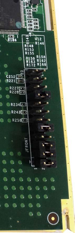


31 Chapter 3 Hardware Introduction FAN setting ( if insert fan on HDD BP ) JFRONT 25


32 Chapter 3 Hardware Introduction Power Connector Power Connector 26
33 Chapter 3 Hardware Introduction Drive Slot Map 27
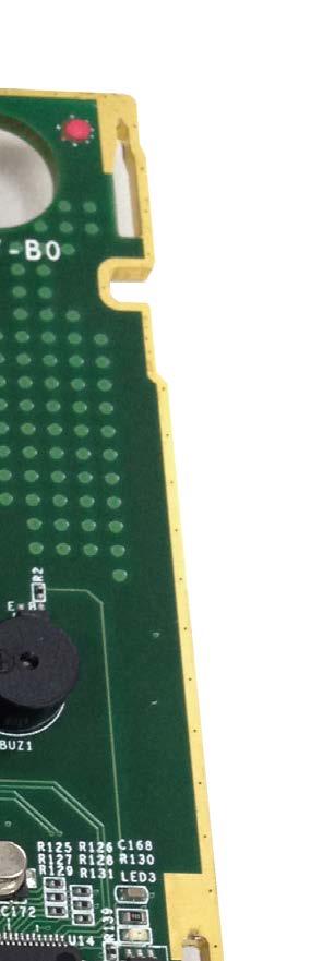
34 Chapter 4 HDD Blackplane Introduction Chapter 4. HDD Blackplane Introduction 4.1 Expender firmware update through phone connector port Update Expander firmware revision Step 1: Set up RSC-4BT phone connector. Insert phone connector into phone connector port shown below also the other side inert cable into host PC or notebook. PLEASE FIND THE PHONE CONNECTOR CABLE IN THE PACKAGE BOX. 28

35 Chapter 4 HDD Blackplane Instruction Step 2: Set up RSC-4BT connector connection Set up connector connection application into your RSC-4BT as shown in the example process below. For example: OS: Microsoft Windows RS232 connection application: Hyperterminal Step 2: Install HyperTrm.exe 29


36 Chapter 4 HDD Blackplane Introduction Step 3: Enter a new name for the icon in the field below and click OK. Step 4: Connecting by using selecting an option in the drop down menu circled in red below (we selected COM2 in this example) and click OK. 30

37 Chapter 4 HDD Blackplane Instruction Step 5: For Bits per second, select For Flow control, select: None. Click OK when you have finished your selections. Properties Port Setting Bits per second: Data bits: Parity: None Stop bits: Flow control: None Restore Defaults OK Cancel Apply Step 6 : Set up is complete. The diagram below depicts what screen should displayed. cmd>_ 31
38 Chapter 4 HDD Blackplane Introduction Step 7:To get firmware image & MFG Configuration Image version information from ''AIC SAS Related Firmware Downloadne'' website. 32
39 Chapter 4 HDD Blackplane Instruction Step 8: Comand line for show current firmware revision. cmd>rev 33
40 Chapter 4 HDD Blackplane Introduction Step 9: Start to update expander firmware cmd>fdl 0 0_ Step 10: Select the tool bar ''Transfer'' -> ''Send File''. 34

41 Chapter 4 HDD Blackplane Instruction Step 11: Choose new firmware path file ''fw 3A1_v ''. Protocol have to choose ''Xmodem''. Step 12: Firmware download complete 35
42 Chapter 4 HDD Blackplane Introduction Step 13: Reset computer for success update firmware. cmd>reset reset 36
43 Chapter 4 HDD Blackplane Instruction Update expander configuration MFG Step 1: Comand line for show current configuration MFG cmd> showmfg 37

44 Chapter 4 HDD Blackplane Introduction Step 2: Start to update expander configuration MFG cmd>fdl 83 0_ Step 3: Select the tool bar ''Transfer'' -> ''Send File''

45 Chapter 4 HDD Blackplane Instruction Step 4: Choose new MFG path file ''mfg 3A1.0_eob_ bin''. Protocol have to choose ''Xmodem''. Step 5: MFG download complete. 39

46 Chapter 4 HDD Blackplane Introduction Step 6: Reset computer for success update MFG. cmd>reset reset 40


47 Chapter 4 HDD Blackplane Instruction 4.2 Update the expander firmware through in-band. FOR EXAMPLE Step 1: Download and install SG3_utils.exe which compatible with Linux OS. From website website Reference version sg3_utils-1.40.tgz Step 2: To get firmware image & MFG Configuration Image version information from ''AIC SAS Related Firmware Downloadne'' website. 41
48 Chapter 4 HDD Blackplane Introduction Step 3: Execute terminal under the same new firmware folder. example: Setting a new firmware folder on ''Home'' page. Open Terminal by click to the right button of mouse in the same window ''Home''. Step 4: Typing ''sudo -s'' to into administrator mode. 42

49 Chapter 4 HDD Blackplane Instruction Step 5: Find expander location. $ sg_map -i Step 6: Update Expander firmware $ sg_write_buffer --id=0x0 --in=fw3a1_v mode=0x2 --offset=0 / dev/sg0 43


50 Chapter 4 HDD Blackplane Introduction Step 7: Update Expander MFG $ sg_write_buffer --id=0x83 --in=mfg3a1.0_eob_ bin --mode=0x2 --offset=0 /dev/sg0 Step 8: Reboot computer for success update firmware & MFG. root@ubuntu:~# reboot 44
51 Chapter 4 HDD Blackplane Instruction G expander EDFB setting Step 1: For Install HyperTerminal.exe refer to section 4.1 Step 2 : Get EDFB status cmd> edfb 45
52 Chapter 4 HDD Blackplane Introduction Step 3: Change EDFB setting Enable EDFB function cmd>edfb on Disable EDFB function cmd>edfb off cmd >edfb EDFB is OFF cmd >edfb on Succeeded to set EDFB cmd >edfb off EDFB is OFF 46

53 Chapter 4 HDD Blackplane Instruction 4.4 Slot HDD power setting (Only for system cooling Fan controled by expander.) Step 1: For Install sg3.exe tool and get new firmware from website refer to section 4.2 Step 2: Execute terminal under the same new firmware folder. example: Setting a new firmware folder on ''Home'' page. Open Terminal by click to the right button of mouse in the same window ''Home''. 47
54 Chapter 4 HDD Blackplane Introduction Step 3: Typing ''sudo -s'' to into administrator mode. Step 4: Find expander location. $ sg_map -i 48


55 Chapter 4 HDD Blackplane Instruction Step 5: For example: If would like to turn the Disk004 power off under the HBA card. Need to check Disk004 power status. $ sg_ses --page=7 /dev/sg0 Under HBA card the Element 3 = Disk
 power")

56 Chapter 4 HDD Blackplane Introduction Step 6: To check Disk004 (element 3) power status is ok $ sg_ses --page=2 /dev/sg0 S Status shows below: The status of Element 3 is OK. 50
57 Chapter 4 HDD Blackplane Instruction Step 7: Turn off a HDD power $ sg_ses --descriptor=disk004 --set=3:4:1 /dev/sg0 Step 8: Turn on a HDD power $ sg_ses --descriptor=disk004 --clear=3:4:1 /dev/sg0 51
58 Chapter 4 HDD Blackplane Introduction 4.5 HDD BP thermal sensor temperature setting (Only for system cooling Fan controled by expander.) Step 1: For Install HyperTerminal.exe refer to section 4.1 Step 2: Get the current temperature settings cmd> temperature 52
59 Chapter 4 HDD Blackplane Instruction Step 3. For example: Set new temperature T1=20 C 4 18 C T2=50 C 4 52 C Warning threshold=50 C 448 C Alarm threshold=55 C 454 C The new setting will take effect after reset. cmd> temperature cmd> reset 53
60 Chapter 4 HDD Blackplane Introduction Step 4. Check fan speed & temperature information. cmd> sensor cmd >sensor ==ENCLOSURE STATUS========================================================== Total fan number : 2 System Fan-0 speed : RPM System Fan-1 speed : RPM System PWN-0 : 82% Expander Temperature : 76 Celsius degree Sytem Temperature-0 : 33 Celsius degree T1 : 20 Celsius degree T2 : 50 Celsius degree TC : 55 Celsius degree Voltage Sensor 0.9V : 0.93V Voltage Sensor 1.8V : 1.80V cmd >_ 54
61 Chapter 1 Product Introduction Chapter 5. Technical Support TAIWAN Tel: Fax: sales@aicipc.com.tw CHINA Tel: , Fax: Extension: 608 Technical Support: support@aicipc.com AMERICA - West coast Tel: Fax: sales@aicipc.com AMERICA - East coast Tel: Fax: njsales@aicipc.com EUROPE Tel: Fax: sales@aicipc.nl Technical Support: support@aicipc.com
RSC-2ET Rackmount Storage Chassis User Manual
 RSC-2ET Rackmount Storage Chassis User Manual UM_RSC-2ET_Final_061815 CONTENTS PREFACE... i SAFETY INSTRUCTIONS... ii Chapter 1. Prodcut Introduction... 1 1.1 Box Content...1 1.2 Specifications...2 1.3
RSC-4ET Rackmount Storage Chassis User Manual
 RSC-4ET Rackmount Storage Chassis User Manual UM_RSC-4ET_v.3_042616 CONTENTS PREFACE... i SAFETY INSTRUCTIONS... ii Chapter 1. Prodcut Introduction... 1 1.1 Box Content...1 1.2 Specifications...2 1.3 General
RSC-1R Rackmount Storage Chassis User's Manual
 RSC-1R Rackmount Storage Chassis User's Manual UM_RSC-1R_v.1_071216 CONTENTS PREFACE... i SAFETY INSTRUCTIONS... ii Chapter 1. Prodcut Introduction... 1 1.1 Box Content...1 1.2 Specifications...2 1.3 General
SATA II HDD Canister KISS DA 435 Quick Reference Guide
 SATA II HDD Canister KISS DA 435 Quick Reference Guide If it s embedded, it s Kontron 1. Table of Contents SATA II HDD Canister KISS DA 435 1. Table of Contents 1. Table of Contents... 1 2. Important Information...
3-4 SAS/SATA II HDD Canister Entry version USER S MANUAL XC-34D1-SA10-0-R. Document number: MAN A
 3-4 SAS/SATA II HDD Canister Entry version XC-34D1-SA10-0-R USER S MANUAL Document number: MAN-00077-A ii Preface Important Information Warranty Our product is warranted against defects in materials and
64 Bays SAS to SAS/SATA JBOD Subsystem. User Manual. Revision 1.0
 64 Bays SAS to SAS/SATA JBOD Subsystem Revision 1.0 Table of Contents Preface... 4 Before You Begin... 5 Safety Guidelines... 5 Controller Configurations... 5 Packaging, Shipment and Delivery... 5 Unpacking
SAS JBOD Installation Reference Guide Revision 1.0
 SAS JBOD 16-bay Rackmount Enclosure Installation Reference Guide Revision 1.0 P/N: PW0020000000281 Copyright No part of this publication may be reproduced, stored in a retrieval system, or transmitted
User Manual AIMB-C200. Economical Embedded Chassis for Mini-ITX Motherboard
 User Manual AIMB-C200 Economical Embedded Chassis for Mini-ITX Motherboard Copyright The documentation and the software included with this product are copyrighted 2010 by Advantech Co., Ltd. All rights
CSE-M14T Mobile Rack USER'S GUIDE
 SUPER CSE-M14T Mobile Rack USER'S GUIDE Rev. 1.0 CSE-M14T Mobile Rack User's Guide The information in this User s Guide has been carefully reviewed and is believed to be accurate. The vendor assumes no
JanusRAID SA-6692J Hardware User Manual
 JanusRAID SA-6692J Hardware User Manual 42-30000-5067 SATA II JBOD enclosure Version 1.1 SA-6692J SATA II JBOD enclosure Hardware User Manual Table of Contents Preface... i Chapter 1 System Requirements
Upgrading and Servicing Guide
 Upgrading and Servicing Guide Copyright Information The only warranties for Hewlett-Packard products and services are set forth in the express statements accompanying such products and services. Nothing
Upgrading and Servicing Guide
 Upgrading and Servicing Guide The only warranties for Hewlett-Packard products and services are set forth in the express statements accompanying such products and services. Nothing herein should be construed
Replacing the Battery HP t5730 and t5735 Thin Clients
 Replacing the Battery HP t5730 and t5735 Thin Clients Copyright 2009 Hewlett-Packard Development Company, L.P. The information contained herein is subject to change without notice. Microsoft and Windows
MIC-3002A Series. 3U 6-slot CompactPCI Enclosures with Rear I/O and 6" LCD. User Manual
 MIC-3002A Series 3U 6-slot CompactPCI Enclosures with Rear I/O and 6" LCD User Manual Copyright The documentation and the software included with this product are copyrighted 2005 by Advantech Co., Ltd.
User Manual. 1U LCD Keyboard Drawer. KwikDraw - A Series. Manual. IT and Instrumentation for industry. - With KVM options - 15", 17, 19 screen size
 User Manual 1U LCD Keyboard Drawer KwikDraw - A Series - With KVM options - 15", 17, 19 screen size 1.1 Important Safeguards Please read all of these instructions carefully before you use the device. Save
742S 742i SC742 CHASSIS USER'S GUIDE
 742S 742i SC742 CHASSIS USER'S GUIDE 1.0a SC742 Chassis User s Guide The information in this User s Guide has been carefully reviewed and is believed to be accurate. The vendor assumes no responsibility
Serial ATA Hot Swap Drive Cage Upgrade Kit for: Intel Server Chassis SC5200 Intel Server Chassis SC5250-E
 Serial ATA Hot Swap Drive Cage Upgrade Kit for: Intel Server Chassis SC5200 Intel Server Chassis SC5250-E A Guide for Technically Qualified Assemblers of Intel Identified Subassemblies/Products Order Number:
120Ra-1 Pentium III Processor Installation Insert
 120Ra-1 Pentium III Processor Installation Insert PN: 455-01614-000 Proprietary Notice and Liability Disclaimer The information disclosed in this document, including all designs and related materials,
EMC1600 Series Media Converter and Ethernet Extender Chassis
 EMC1600 Series Media Converter and Ethernet Extender Chassis User s Manual Preface This manual describes how to install and use the 16-Bay Media Converter and Ethernet Extender Chassis. This chassis is
Upgrading and Servicing Guide
 Upgrading and Servicing Guide The information in this document is subject to change without notice. Hewlett-Packard Company makes no warranty of any kind with regard to this material, including, but not
AerMonitor AM Aer Monitor User's Manual. Version-0.1
 AerMonitor AM-1015 Aer Monitor User's Manual Version-0.1 AerMonitor AM-1015 Copyright Notice This document is copyrighted, 2013. All rights are reserved. Firich Enterprise Co., Ltd reserves the right to
Installing the Cisco SFS 3504 Server Switch
 CHAPTER 3 This chapter describes how to mount your Cisco SFS 3504 Server Switch on a rack, boot the Cisco SFS 3504 Server Switch, and configure basic services. For advanced configuration information, see
350 East Plumeria Drive San Jose, CA USA May
 Installation Guide 350 East Plumeria Drive San Jose, CA 95134 USA May 2012 201-15135-02 NETGEAR, Inc. All rights reserved. No part of this publication may be reproduced, transmitted, transcribed, stored
Obtaining Documentation and Submitting a Service Request, page xvii Safety Warnings, page xvii Safety Guidelines, page xx
 Preface Obtaining Documentation and Submitting a Service Request, page xvii Safety s, page xvii Safety Guidelines, page xx Obtaining Documentation and Submitting a Service Request For information on obtaining
TRC-190 User s Manual
 User s Manual Edition 3.2, May 2017 www.moxa.com/product 2017 Moxa Inc. All rights reserved. User s Manual The software described in this manual is furnished under a license agreement and may be used only
MIC-3001/8. 3U/4U CompactPCI. Enclosure for Rackmounting
 MIC-3001/8 3U/4U CompactPCI Enclosure for Rackmounting Copyright Notice This document is copyrighted, 1999. All rights are reserved. The original manufacturer reserves the right to make improvements to
FCC COMPLICANCE STATEMENT
 FCC COMPLICANCE STATEMENT For Users in the USA This equipment has been tested and found to comply with the limits for a Class B digital device, pursuant to Part 15 of FCC Rules. These rules are designed
TRC-190 User s Manual
 First Edition, November 2008 www.moxa.com/product 2008 Moxa Inc. All rights reserved. Reproduction without permission is prohibited. The software described in this manual is furnished under a license agreement
SAS to SAS/SATA JBOD Subsystem. User Manual. Revision 1.2
 SAS to SAS/SATA JBOD Subsystem Revision 1.2 Table of Contents Chapter 1 Introduction... 3 1.1 Features... 4 1.2 Technical Specifications... 5 1.3 Unpacking the JBOD Subsystem... 6 1.4 Identifying Parts
Industrial Rack-mount LCD KVM Drawer. User Manual. 8 -Port KVM Drawer 16-Port KVM Drawer
 Industrial Rack-mount LCD KVM Drawer User Manual 8 -Port KVM Drawer 16-Port KVM Drawer TABLE OF CONTENTS 4 Packing Contents 4 Safety Instructions 6 Introduction 6 Feature 8 Specification 10 Panel Description
Table of Contents Quick Install Guide page Introduction Safety Rack System Precautions ESD Precautions...
 Table of Contents Quick Install Guide page 1 EN English Table of Contents 1. Introduction... 2 1.1 Safety... 2 1.2 Rack System Precautions... 2-3 1.3 ESD Precautions... 3... 3 1... 3 2 Fitting PSU s...
Upgrading and Servicing Guide
 Upgrading and Servicing Guide Copyright Information The only warranties for Hewlett-Packard products and services are set forth in the express statements accompanying such products and services. Nothing
Manual Version: V1.00. Video Decoder Quick Guide
 Manual Version: V1.00 Video Decoder Quick Guide Thank you for purchasing our product. If there are any questions, or requests, please do not hesitate to contact the dealer. Copyright Copyright 2016 Zhejiang
16-SLOT IN-BAND MANAGEMENT CHASSIS
 FCM-CHS2-XX 16-SLOT IN-BAND MANAGEMENT CHASSIS User's Guide. Version 1.6 FCC Warning This equipment has been tested and found to comply with the limits for a Class A digital device, pursuant to Part 15
Rocsecure NE52 NAS System
 Rocsecure NE52 NAS System Revision 1.0 Table of Contents Preface... 3 Before You Begin... 4 Safety Guidelines... 4 Packaging, Shipment and Delivery... 4 Chapter 1 Introduction... 5 1.1 Key Features...
LevelOne KVM User Manual. 17 Modularized KVM Console V
 LevelOne KVM-0217 17 Modularized KVM Console User Manual V1.0.0-0708 SAFETY INSTRUCTIONS 1. Please read these safety instructions carefully. 2. Please keep this User Manual for later reference. 3. Please
CHASSIS INSTALLATION GUIDE
 SUPER SC942S-600 SC942i-600/550 SC942 CHASSIS INSTALLATION GUIDE 1.0 SUPER SC942 Chassis User's Guide Table of Contents Chapter I: Unpacking and Check Lists... 1-3 Chapter 2: Installation Procedures...
TABLE OF CONTENTS INTRODUCTION...1 DEVICE SETUP...4 SUPPORT RESOURCES...9
 TABLE OF CONTENTS INTRODUCTION...1 1.1 Minimum System Requirements 1.2 Package Contents 1.3 About This Manual 1.4 Rear View 1.4.1 Rear Features 1.5 Usage Notes DEVICE SETUP...4 2.1 Quick Start 2.2 Assembly
HP ProLiant DL165 G7 Server
 HP ProLiant DL165 G7 Server Installation Instructions Part Number 601464-003 Identifying server components Front panel components Figure 1 Front Panel Components / 4 3.5 LFF HDD Item Description 1 Thumbscrews
user manual AMOS-2000 Universal Compact, Chassis System, Supporting Nano-ITX Embedded Boards Revision
 Revision 0.20 020-10122009-1415 user manual AMOS-2000 Universal Compact, Chassis System, Supporting Nano-ITX Embedded Boards Copyright and Trademarks Copyright 2009 VIA Technologies Incorporated. All rights
Chassis (FRU) Replacement Guide
 Replacement Guide") SIEM9750 Release 1.0 Chassis (FRU) Replacement Guide Issue: 02 Date: 2011-11-07 Page 1 of 26 This document is intended for Symantec support personnel, IBM, or other authorized Symantec Service Partners.
SIEM9750 Release 1.0 Chassis (FRU) Replacement Guide Issue: 02 Date: 2011-11-07 Page 1 of 26 This document is intended for Symantec support personnel, IBM, or other authorized Symantec Service Partners.
Keysight E5864A Removable Hard Drive for Series Logic Analyzers. Installation Guide
 Keysight E5864A Removable Hard Drive for 16850-Series Logic Analyzers Installation Guide Notices Keysight Technologies 2013-2014 No part of this manual may be reproduced in any form or by any means (including
350 East Plumeria Drive San Jose, CA USA February
 Installation Guide 350 East Plumeria Drive San Jose, CA 95134 USA February 2013 201-15135-03 Support Thank you for selecting NETGEAR products. After installing your device, locate the serial number on
Mercury Helios ASSEMBLY MANUAL & USER GUIDE
 Mercury Helios ASSEMBLY MANUAL & USER GUIDE TABLE OF CONTENTS INTRODUCTION...1 1.1 MINIMUM SYSTEM REQUIREMENTS 1.1.1 Apple Mac Requirements 1.1.2 PC Requirements 1.1.3 Supported PCIe Cards NOTE: Boot Camp
Quick Installation Guide
 Quick Installation Guide For Network Attached Storage Ver.1.1.0.0517 Table of Contents Notices... 3 Safety Precautions... 4 1. Package Contents... 5 2. Hardware Installation Guide... 6 2.1. Hard Disk Installation...
Quick Installation Guide
 Quick Installation Guide For Network Attached Storage Ver.1.1.0.0320 Table of Contents Notices... 3 Safety Precautions... 4 1. Package Contents... 5 2. Hardware Installation Guide... 6 2.1. Hard Disk Installation...
RPC-600/610. Industrial Chassis USER' Manual
 RPC-600/610 Industrial Chassis USER' Manual RPC-600/610 Industrial Chassis USER' Manual Headquarters (China):86-0755-27331166 Shenzhen:86-0755-27331166 Beijing:86-010-82671166 Shanghai:86-021-61212088
Motion LE1700 Tablet PC Hard Disk Drive Upgrade Procedure
 Motion LE1700 Tablet PC Hard Disk Drive Upgrade Procedure 2008 Motion Computing, Inc. All rights reserved. This document contains information protected by copyright. No part of this document may be reproduced
SAS to SAS/SATA JBOD Subsystem. User Manual. Revision 1.1
 SAS to SAS/SATA JBOD Subsystem Revision 1.1 Table of Contents Chapter 1 Introduction... 3 1.1 Features... 4 1.2 Technical Specifications... 5 1.3 Unpacking the JBOD Expansion Chassis... 6 1.4 Identifying
dedicated KVM switch and rackmount screen technology User Manual CV-1201D DVI-D KVM Designed and manufactured by Austin Hughes
 dedicated KVM switch and rackmount screen technology User Manual CV-1201D DVI-D KVM Designed and manufactured by Austin Hughes 751 Legal Information First English printing, October 2002 Information in
Customer Replacement Procedure
 Customer Replacement Dell EMC Unity Family Dell EMC Unity All Flash and Unity Hybrid Replacing a faulted 80-drive DAE cooling module 302-003-777 REV 01 July 2017 This document describes how to replace
J SAS/SATA JBOD User's Manual. UM_J _v.5_120216
 J4060-01 SAS/SATA JBOD User's Manual UM_J4060-01_v.5_120216 CONTENTS PREFACE...i SAFETY INSTRUCTIONS... ii Chapter 1. Prodcut Introduction...1 1.1 Box Content...1 1.2 Specifications...2 1.3 General Information...
LVN5200A-R2, rev. 1, Hardware Installation Guide
 LVN5200A-R2 LVN5250A-R2 LVN5200A-R2, rev. 1, Hardware Installation Guide Customer Support Information Order toll-free in the U.S.: Call 877-877-BBOX (outside U.S. call 724-746-5500) FREE technical support
EVO-TM2A EVO-TM2B Touch Screen Monitor
 User Manual Revision v1.3 Dec. 2010 EVO-TM2A EVO-TM2B Touch Screen Monitor Copyright 2010 August All Rights Reserved Manual Version 1.3 Part Number: The information contained in this document is subject
Dell XPS 14z Owner s Manual
 Dell XPS 14z Owner s Manual Computer model: L412z Regulatory model: P24G series Regulatory type: P24G001 Notes, Cautions, and Warnings NOTE: A NOTE indicates important information that helps you make better
Quick Installation Guide
 Quick Installation Guide Applicable Models: AS6004U Ver.3.0.0 (2017-4-13) Table of Contents Notices... 3 Safety Precautions... 4 1. Package Contents... 5 2. Optional Accessories... 6 3. Hardware Installation
Installing the Cisco ADE 2130 and 2140 Series Appliance Hardware Options
 CHAPTER 4 Installing the Cisco ADE 2130 and 2140 Series Appliance Hardware Options This chapter provides instructions for installing, replacing, and removing various hardware options in your Cisco ADE
HP UPS R/T3000 ERM. Overview. Precautions. Installation Instructions
 HP UPS R/T3000 ERM Installation Instructions Overview The ERM consists of two battery packs in a 2U chassis. The ERM connects directly to a UPS R/T3000 or to another ERM. Up to two ERM units can be connected.
Tower to Rack and Rack to Tower System Conversion Guide
 Tower to Rack and Rack to Tower System Conversion Guide HP Workstation zx6000 HP Server rx2600 Manufacturing Part Number : A7857-90017 Edition E0802 Copyright 2002 Hewlett-Packard Company. Legal Notices
Installing and Managing the Switch
 CHAPTER 2 This chapter describes how to install and manage the Cisco SFS 7008 system hardware and contains these sections: Safety, page 2-2 Preparing the Site, page 2-3 Rack-Mounting the Switch, page 2-4
HP ProLiant MicroServer
 HP ProLiant MicroServer Installation Sheet Part Number 615715-004 Panel door components Item Component 1 16 screws for HDD installation 2 4 screws for ODD installation 3 Screw driver Rear panel components
SAS to SAS/SATA JBOD Subsystem. User Manual. Revision 1.1
 SAS to SAS/SATA JBOD Subsystem Revision 1.1 Table of Contents Chapter 1 Introduction... 3 1.1 Features... 4 1.2 Technical Specifications... 5 1.3 Unpacking the JBOD Expansion Chassis... 6 1.4 Identifying
Thank you for selecting UTC RETAIL s innovative Model 1170 Point of Sale solution!
 1170 POS SYSTEM 1170 INSTALLATION GUIDE Thank you for selecting UTC RETAIL s innovative Model 1170 Point of Sale solution! This Installation Guide will help you efficiently install the 1170 POS. The document
Toll Free: Tel: Fax:
 Toll Free: 1-888-865-6888 Tel: 510-226-8368 Fax: 510-226-8968 Email: sales@rackmountmart.com User Manual LCDK 1070 DVI-D KVM Legal Information First English printing, October 2002 Information in this document
LevelOne. KVM-0115/KVM / 17-inch LCD KVM Rack Console. User Manual. Version
 LevelOne KVM-0115/KVM-0117 15 / 17-inch LCD KVM Rack Console User Manual Version 1.0-1305 1 SAFETY INSTRUCTIONS 1. Please read these safety instructions carefully. 2. Please keep this User Manual for later
Managing Individual Components
 CHAPTER 3 This chapter describes how to install the Field Replaceable Units (FRUs) in the Cisco SFS 7008P system. About the Field Replaceable Units The following Field Replaceable Units (FRUs) are a part
Hard Drive/Solid-State Drive Replacement Instructions
 Hard Drive/Solid-State Drive Replacement Instructions 925496-001 Before you begin Observe the following requirements before removing and replacing the hard drive or solid-state drive. WARNING: To reduce
Installing and Configuring Rialto Analytic Appliances
 Installing and Configuring Rialto Analytic Appliances Important Safety Information This manual provides installation and operation information and precautions for the use of this camera. Incorrect installation
Mercury Elite Pro mini ASSEMBLY MANUAL & USER GUIDE
 Mercury Elite Pro mini ASSEMBLY MANUAL & USER GUIDE TABLE OF CONTENTS 1. INTRODUCTION... 1 1.1 MINIMUM SYSTEM REQUIREMENTS 1.1.1 Mac Requirements 1.1.2 PC Requirements 1.2 PACKAGE CONTENTS 1.3 ABOUT THIS
DNS User Manual. Version Dec DataON Storage, storage division of Area Data Systems.
 DNS-2670 User Manual Version Dec. 2015 DataON Storage, storage division of Area Data Systems. Contents 1 Introduction... 1 1.1 System Overview... 3 1.1.1 System Top View...3 1.1.2 Front View...4 1.1.3
Upgrading and Servicing Guide
 Upgrading and Servicing Guide The information in this document is subject to change without notice. Hewlett-Packard Company makes no warranty of any kind with regard to this material, including, but not
User Manual IPC U Industrial Rackmount Chassis for SHB and SBC
 User Manual IPC-602 2U Industrial Rackmount Chassis for SHB and SBC Copyright The documentation and the software included with this product are copyrighted 2009 by Advantech Co., Ltd. All rights are reserved.
Dell Inspiron N5110 Service Manual
 Dell Inspiron N5110 Service Manual Regulatory model: P17F Regulatory type: P17F001 Notes, Cautions, and Warnings NOTE: A NOTE indicates important information that helps you make better use of your computer.
Model 2380 Rack-Mount Kit
 Keithley Instruments 28775 Aurora Road Cleveland, Ohio 44139 1-800-935-5595 http://www.tek.com/keithley Model 2380 Rack-Mount Kit Installation Instructions Introduction The Model 2380 Fixed Rack-Mount
Upgrading and Servicing Guide
 Upgrading and Servicing Guide The only warranties for Hewlett-Packard products and services are set forth in the express statements accompanying such products and services. Nothing herein should be construed
Tiger Box Expansion Chassis Assembly Guide
 Tiger Box Expansion Chassis Assembly Guide Product Overview................................. 3 Tiger Box Expansion Chassis Features............... 3 Package Content............................. 4 Hardware
Installation Manual. Mounting Instructions Mechanical Mounting. Luminato. Teleste Corporation
 Luminato Installation Manual Teleste Corporation Mounting Instructions Mechanical Mounting Luminato Mechanical Installation, agile_59300316, rev0044 Introduction 1 Contents Introduction 4 General... 4
Bluetooth Shielding Instructions
 Mac mini 2012 Bluetooth Shielding Instructions 1 INTRODUCTION 1.1 STATIC PRECAUTIONS 1.2 TOOLS REQUIRED 2 DISASSEMBLY 3 SHIELDING 4 FAQ 4.1 FAQ 5 CUSTOMER SERVICE 5.1 Before Contacting Customer Service
Replacing an Advanced Power and Cooling (APC) Unit
 Unit") Replacing an Advanced Power and Cooling (APC) Unit You must replace a failed APC unit as quickly as possible (within minutes) to maintain correct airflow and cooling. Failed APC units can be hot-swapped.
Replacing an Advanced Power and Cooling (APC) Unit You must replace a failed APC unit as quickly as possible (within minutes) to maintain correct airflow and cooling. Failed APC units can be hot-swapped.
Fujitsu Stylistic ST4000 Series TABLET DOCK USER S GUIDE
 Fujitsu Stylistic ST4000 Series TABLET DOCK USER S GUIDE DECLARATION OF CONFORMITY according to FCC Part 15 Responsible Party Name: Fujitsu PC Corporation Address: 5200 Patrick Henry Drive Santa Clara,
OWC Mercury Helios 2 ASSEMBLY MANUAL & USER GUIDE
 OWC Mercury Helios 2 ASSEMBLY MANUAL & USER GUIDE TABLE OF CONTENTS 1. INTRODUCTION...1 1.1 MINIMUM SYSTEM REQUIREMENTS 1.1.1 Apple Mac Requirements 1.1.2 PC Requirements 1.1.3 Supported PCIe Cards 1.2
Sun StorageTek. 1U Rackmount Media Tray Reference Guide. Sun Doc Part Number: Second edition: December 2007
 Sun StorageTek nl 1U Rackmount Media Tray Reference Guide Sun Doc Part Number: 875 4297 10 Second edition: December 2007 Legal and notice information Copyright 2007 Hewlett Packard Development Company,
Sivy SA-4327S Hardware User Manual
 Sivy SA-4327S Hardware User Manual esata to Serial ATA II Disk Array System Version 1.0 SA-4327S esata to Serial ATA II Disk Array System Hardware User Manual Table of Contents Preface... i Chapter 1
DATA DOUBLER. Apple Mac mini (2009)
") DATA DOUBLER Apple Mac mini (2009) TABLE OF CONTENTS Introduction... 1 1.1 Hardware Compatibility 1.1.1 Host Computer Compatibility 1.1.2 Drive Compatibility 1.2 Package Contents 1.3 About This Manual
DATA DOUBLER Apple Mac mini (2009) TABLE OF CONTENTS Introduction... 1 1.1 Hardware Compatibility 1.1.1 Host Computer Compatibility 1.1.2 Drive Compatibility 1.2 Package Contents 1.3 About This Manual
ALIENWARE AURORA SERVICE MANUAL 01/
 ALIENWARE AURORA SERVICE MANUAL 01/ 01 Notes, Cautions, and Warnings NOTE: A NOTE indicates important information that helps you make better use of your computer. CAUTION: A CAUTION indicates either potential
3-Phase, Dual-Input 6-Slot Power Supply System STARTUP GUIDE
 3-Phase, Dual-Input 6-Slot Power Supply System STARTUP GUIDE -ST-01 Page 1 of 10 November 2016 2016 Copyright Lite-On Technology Corporation ALL RIGHTS RESERVED. Lite-On is a trademark of Lite-On Technology
MIC-3001/8. 3U/4U CompactPCI Enclosure for Rack Mounting. User Manual
 MIC-3001/8 3U/4U CompactPCI Enclosure for Rack Mounting User Manual Copyright The documentation and the software included with this product are copyrighted 2004 by Advantech Co., Ltd. All rights are reserved.
5.25in Bay IDE Hard Drive Mobile Rack
 5.25in Bay IDE Hard Drive Mobile Rack DRW110ATA / DRW110ATABK *DRW110ATABK shown *actual product may vary from photos DE: Bedienungsanleitung - de.startech.com FR: Guide de l'utilisateur - fr.startech.com
FUSION 400. User s Guide. 4-Bay Serial ATA Hot-Swap Drive Enclosure. For Windows
 FUSION 400 4-Bay Serial ATA Hot-Swap Drive Enclosure User s Guide For Windows Fusion 400 Specifications and Features Drive Tray (Slot 1) Drive Tray (Slot 2) Drive Tray (Slot 3) Drive Tray (Slot 4) Specifications
easyraid Q24P2-U4R4 Hardware Manual
 easyraid Q24P2-U4R4 Hardware Manual 42-30000-5105 SCSI Channel to Serial ATA II Disk Array System Version 1.0 easyraid Q24P2-U4R4 U320 SCSI Channel to Serial ATA II Disk Array System Hardware User Manual
ITA-1711 Series Fanless Compact Embedded IPC with Intel Celeron Dual Core CPU Startup Manual
 ITA-1711 Series Fanless Compact Embedded IPC with Intel Celeron Dual Core CPU Startup Manual Packing List Specifications Before you begin installing your IPC, please make sure that the following items
SMAVIA Enterprise Storage JBOD Commissioning
 SMAVIA Enterprise Storage JBOD Commissioning English 1.0.0 / 2015-11-12 Copyright 2015 Dallmeier electronic GmbH & Co.KG The reproduction, distribution and utilization of this document as well as the communication
DMC-1000 Chassis-Based Media Converter
 DMC-1000 Chassis-Based Media Converter User s Guide Rev. 01 (Jan. 2002) 6012-9600131 (1907MCR11616000) Printed In Taiwan RECYCLABLE i TABLE OF CONTENTS TABLE OF CONTENTS... II PREFACE... 3 19 MEDIA CONVERTER
DC-V3213XJ-4.3mm DC-V3213XJ-2.5mm
 Network Camera Quick Guide DC-V3213XJ-4.3mm DC-V3213XJ-2.5mm Powered by Safety Precautions WARNING RISK OF ELECTRIC SHOCK DO NOT OPEN WARNING: TO REDUCE THE RISK OF ELECTRIC SHOCK, DO NOT REMOVE COVER
Network Camera. Quick Guide DC-B1203X. Powered by
 Network Camera Quick Guide DC-B1203X Powered by Safety Precautions English WARNING RISK OF ELECTRIC SHOCK DO NOT OPEN WARNING: TO REDUCE THE RISK OF ELECTRIC SHOCK, DO NOT REMOVE COVER (OR BACK). NO USER-SERVICEABLE
Customer Upgrade Procedure
 Customer Upgrade Dell EMC Unity Family Dell EMC Unity All Flash and Unity Hybrid Adding an optional 80-drive DAE disk drive 302-003-780 REV 01 July 2017 This document describes how to add an optional 80-drive
AURA SSD FOR MAC PRO. Installation Guide
 AURA SSD FOR MAC PRO Installation Guide CONTENTS Introduction... 1 1.1 System Requirements 1.2 Package Contents 1.3 About This Manual Installation... 2 2.1 Preparing the Mac Pro 2.2 Installing the Aura
The SC812/SC812L Chassis Series Installation Guide
 SUPER The SC812/SC812L Chassis Series Installation Guide Rev. 1.0 SC812/SC812L Chassis User's Guide Table of Contents Chapter I: Introduction... 1-3 A. Front Panel Connectors... 1-3 B. Front Panel LED
Trayless SATA Drive Bay 5.25" Trayless SATA Hot Swap Drive Bay
 Trayless SATA Drive Bay 5.25" Trayless SATA Hot Swap Drive Bay HSB100SATBK Actual product may vary from photo FCC Compliance Statement This equipment has been tested and found to comply with the limits
G-MAX TM. ATX Series User s Manual
 Copyright Notice Copyright 2001 Gigabyte Technology. All Rights Reserved. No part of this documentation, including but not limited to the products and software described in it, may be reproduced, transmitted,