4K Video Tiler & Presentation Scaler Switcher
|
|
|
- Winfred Adams
- 6 years ago
- Views:
Transcription

1 4K Video Tiler & Presentation Scaler Switcher Supports both models: HDBT- VTSC72-4K HDVTSC72-4K All rights reserved 2016 User Manual V0.5 1 / 67
2 Intro to HDBT- VTSC72-4K & HD- VTSC72-4K The KanexPro HDBT- VTSC72-4K is a 7- input, 2- mirrored (HDMI & HDBaseT) output presentation scaler- switcher engineered to upscale HDMI / DisplayPort and VGA devices such as laptops, Blu- ray players and desktops to a true 4K@30Hz resolution and creating a Quad Window Tiling experience in any collaboration space. Inputs include 4 HDMI, 2 DisplayPort and 1 VGA with mirrored HDMI and HDBaseT output supporting distances over CAT6 up to 70 meters with PoC. This Quad- Viewer can also be controlled via RS- 232 and TCP/IP. It supports native 4K inputs and outputs with breakaway audio switching to support unbalanced stereo. Ideally used in collaboration, meeting rooms, classrooms and video conferencing applications. Features l Multiple inputs: 4 x HDMI, 2 x DisplayPort, 1 x RGB/YPbPr l HDMI,DisplayPort source input with 4Kx2K@30Hz support l Supports MHL in the four HDMI input ports. l Supports Auto Scaler in each source input. l Supports different multiple- window modes of quadruple windows, triple windows, double windows and a single window, outputting to a display device through one HDMI output. l Supports a lot of pre- defined multiple- window mode l HDCP compliant l Fast switch between input ports. l Supports audio 7 x 1 l Supports multiple- channel HDMI, DisplayPort audio extraction, optical fiber and eight- channel analog outputs. l Supports one button fast switch Cable Controller. l Chooses from four control methods Panel, IR, LAN (Web GUI, Telnet & UDP) and RS232 l On- site firmware upgrading through LAN, RS232 or USB ports (reserved for some devices). l 1 U Height, 19 width standard enclosure, rack mountable design l HDBaseT output may be optional depending on the model 2 / 67
3 Table of Contents Getting Started... 5 Panel Layout... 5 Front Panel... 5 Rear Panel... 6 IR Remote Control Unit... 7 Button layout... 7 HDMI/DP Cable Switcher... 8 Installation... 8 How to Connect the Multiviewer Switcher... 8 Application Diagram... 9 Operating Instructions Standby Mode and Work Mode Screen layout Configuration Single Window Double Windows Triple Windows Quadruple Windows Output Resolutions Audio Settings Audio Input Select Audio Output Instructions OSD Setting Instructions Advanced Settings RS232 Settings IP Setting General Control Advanced Control Basis EDID Management Advanced EDID management EDID Assign / 67
4 EDID upload and Download EDID Names EDID commands list WEB Setting General Settings Advanced Settings EDID Network Other Factory Reset Button F/W Update Guide Electrical Parameters / 67

5 Getting Started Panel Layout Front Panel ID Name Description 1 IR receive window IR receive sensor, receives the IR signals from the IR remote. Press the buttons 1~7 to select the 2 Input Buttons and corresponding video or audio input. The Indicator indicators mean the corresponding status of the video or audio input Audio Selection Button and Indicator Video Input Button and Indicator Video Window Mode Button and Indicator Press this button, then the indicator lights up, meaning switching between audio outputs. Press the buttons 1~4, indicating the corresponding windows are selected. The indicators mean whether this window is effective. Video window mode selection: single window, double windows, triple windows and quadruple windows. The indicators mean whether this window is effective. Selects the related resolutions, then the indicators light up. 6 Output Resolution Button and Indicator 7 Power Indicator Indicates when the units have power. l Switches between standby and working 8 mode. Standby button and l When this device is switched to the indicator standby mode, the indicator lights up. l When this device is switched to 5 / 67

6 working mode, the indicator doesn t lights up. Rear Panel ID Name Description Power Switch Turn the power ON or OFF using this switch, Connect and 110/220 1 the included AC power cord to this receptacle and AC Power connect the plug to an available electrical outlet. Receptacle 2 Analog audio output 3 Optical output 4 HDMI output 5 6 Analog audio input 1~7 HDMI input 1~4 8 channel analog audio output, Connect a 3.5mm mini- stereo cable from this jack to the Line In jack of a multimedia system. Connect the optical output port to the digital audio input port of your amplifier Connect an HDMI cable from this port to an HD or 4K displays. 7 channel stereo analog audio input, Connect a 3.5mm mini- stereo cable from the Line Out jack on the audio source to this jack. Connect up to four Hi- Def. sources to these inputs using HDMI cables. 7 DisplayPort input 1~2 Connect up to two Hi- Def. sources to these inputs using DisplayPort cables. 8 RGB/YPbPr input 9 IP Cont. 10 RS- 232 Connect up to Hi- Def. sources to this input using DB- 15 cable or YPbPr- VGA cable. Connect an Ethernet cable between this jack and a LAN to use IP control. Refer to RS- 232 and IP Configuration for more information on setting up IP control. Connect an RS- 232 cable from this port to an RS- 232 device. See RS- 232 and IP Configuration for more information on setting up RS- 232 control. 6 / 67

7 IR Remote Control Unit Button layout ID Name Description 1 Power Press this button to power- ON or power- OFF the Multiviewer Switcher 2 Input 1-7 Press "1-7" buttons to select the corresponding video input or audio input 3 Windows 1-4 Press "1-7" buttons to select the corresponding window for select video input 4 Screen Layout Press this buttons to select Single mode, Double mode, TRIPLE mode and Quadruple mode 5 Audio Press this button and then press the "1-7" buttons to select the corresponding audio input 6 Mute Press this button to Mute or Unmute the Multiviewer Switcher audio output 7 Resolution Press this button to change the Multiviewer Switcher HDMI output resolution 7 / 67

8 HDMI/DP Cable Switcher ID Name Description 1 HDMI/DP Output Connect up to 4K or Hi- Def. HDMI/DP sources 2 Power Indicator Indicates the power indicator. 3 Link Indicator Indicates the connection status indicator. 4 Switch Button Presses this button Multiviewer Switcher to switch to this signal port. 5 HDMI/DP Input Connects to the HDMI or DisplayPort ports of Multiviewer Switcher using the HDMI cables. Installation How to Connect the Multiviewer Switcher 1. Connect up to four 4K or HD HDMI sources to the input ports (HDMI 1 - HDMI 4), Connect up to two 4K or HD DisplayPort sources to the input ports (DISPLAYPORT 5 - DISPLAYPORT 6), Connect up to one Hi- Def. VGA or YPbPr sources to the input ports (RGB/YPbPr) on the Multiviewer Switcher 2. Connect an 4K or HD display to the HDMI Output port on the Multiviewer Switcher 3. OPTIONAL: Connect up seven stereo analog audio sources to audio input ports (1-7) on the Multiviewer Switcher. 4. OPTIONAL: Connect the HDMI/DP input port of HDMI/DP cable switcher to the 4K or HD source device. Connects the HDMI/DP input port of Multiviewer Switcher to the HDMI/DP output port of HDMI/DP cable switcher using HDMI or DP cables. 8 / 67

9 5. OPTIONAL: Connect four 3.5mm mini- stereo cables from the jacks on the Multiviewer Switcher to the Line In jack of a multimedia system, or Connect an optical cables from the OPTICAL on the Multiviewer Switcher to the Optical In of a multimedia system. 6. OPTIONAL: Connect an RS- 232 cable from the RS- 232 port on the Multiviewer Switcher to the RS- 232 connector on the serial controller. 7. OPTIONAL: Connect an Ethernet cable from the LAN port on the Multiviewer Switcher to a Local Area Network (LAN). 8. Connect the AC power cord to the Multiviewer Switcher and connect the plug to an available electrical outlet. Application Diagram 9 / 67


10 Operating Instructions Standby Mode and Work Mode The PWR LED next to the Power button, on the front panel, indicates the power state of the Multiviewer Switcher. This indicator will be red and remain illuminated as long as t power is being supplied to the Multiviewer Switcher. If this indicator does not illuminate, check the connection between the power receptacle on the Multiviewer Switcher and the AC outlet. If the Standby mode is accessed, the Standby indicator lights up until Multiviewer Switcher is waken up. When the normal work mode is accessed, the Standby indicator is off. There three methods to wake up the device: pressing Standby button, pressing ON/OFF button in the IR remote, or using LAN or RS232 commands. 10 / 67

11 Screen layout Configuration This Multiviewer Switcher offers quadruple window configurations: quadruple windows, triple windows, double windows and single window. The screen configuration is shown as follows. Press the four buttons in the Screen Layout of the Multiviewer Switcher, corresponding to the four modes above. For example, if you want to use the mode of quadruple windows, press the button to which is displayed or the button in the remote, the button indicator on the panel lights up, the picture output to the display device through HDMI shows quadruple windows, meanwhile, video 1~4 indicators will light up. 11 / 67

12 This Multiviewer Switcher can display up to four sources. When multiple sources are displayed on the screen, each source is regarded as a single window, and each window is defined as an input. However, we want to define the operation in the single window to introduce the basic operation before introduction to the operation in multiple windows. In the following example, seven HD sources (each of them is displayed as a single picture) are connected to Multiviewer Switcher. When Multiviewer Switcher is delivered from the factory, the default boot settings are loaded automatically. (See below) 12 / 67
 HDMI output configures the HDMI 1 input; the window is shown as follows. 3) If you want to switch to the signal of DisplayPort5.")

13 Single Window 1) Use button on the front panel or in the remote to set to the single window mode, Video 1 button indicator lights up, and Input 1 indicator lights up. 2) HDMI output configures the HDMI 1 input; the window is shown as follows. 3) If you want to switch to the signal of DisplayPort5. Method 1: directly press the INPUTS 5 button on the front panel or in the remote. Method 2: first press Video 1 button on the front panel or in the remote, the 1 button indicator on the panel turns solid on, 2~7 button indicators are blinking (If an indicator is solid on, it means the source currently selected; If an indicator is blinking, it means the source which can be selected), press the INPUTS 1 button on the front panel or in the remote. 4) The 5 button indicator lights up, the panel status is shown as follows. 13 / 67
 Use the button on the front panel or in the remote to set to the mode of double windows, Video 1 and 2 button indicators on the front panel light on.")
; Window 2 is configured to HDMI2 input (HDMI2 is the factory default. If any changes are made, use the last configuration).")
14 5) HDMI output picture is changed to the signal of DisplayPort5. Double Windows 1) Use the button on the front panel or in the remote to set to the mode of double windows, Video 1 and 2 button indicators on the front panel light on. 2) HDMI output port outputs the mode of double windows. Window 1 is configured to HDMI 1 input (HDMI1 is the factory default. If any changes are made, use the last configuration); Window 2 is configured to HDMI2 input (HDMI2 is the factory default. If any changes are made, use the last configuration). The windows are shown as follows. 3) For example, if you want to switch to Window 1, and if you want to switch the signal of DisplayPort5. Method 1: directly press the INPUTS 5 button on the front panel or in the remote, the Video 1 and 2 button indicators blink (indicates that the two buttons can be selected), press the Video 1 14 / 67

15 button on the front panel or in the remote to select Window 1. Method 2: first press the Video 1 button on the front panel or in the remote, the 1 button indicator on the panel turns solid on, 2~7 button indicators are blinking (If an indicator is solid on, it means the source currently selected; If an indicator is blinking, it means this source can be selected), press the INPUTS 1 button on the front panel or in the remote. 4) Windows 2 can select DisplayPort6 using the same method. 5) When the INPUTS indicators are off, the panel status is shown as follows. 6) HDMI output picture is changed to the status below. Triple Windows 1) Use button on the front panel or in the remote to set to the mode of triple windows, Video 1, 2 and 3 button indicators on the front panel light up. 2) HDMI output port outputs the mode of triple windows. Window 1 is configured to HDMI1 input (HDMI1 is the factory default. If any changes are made, use the last configuration); Window 2 is configured to HDMI2 input (HDMI2 is the factory default. If any changes are made, use the last configuration); Window 3 is configured to HDMI3 input (HDMI3 is the factory default. If any changes are made, use the last configuration). The windows are shown as follows. 15 / 67
, press the Video 1 button on")
16 3) For example, if you want to switch to Window 1, and if you want to switch the signal of DisplayPort5. Method 1: directly press the INPUTS 5 button on the front panel or in the remote, the Video 1 and 2 button indicators blink (indicates the two buttons can be selected), press the Video 1 button on the front panel or in the remote to select Window 1. Method 2: first press the Video 1 button on the front panel or in the remote, the 1 button indicator on the panel turns solid on, 2~7 button indicators are blinking (If an indicator is solid on, it means the source currently selected; If an indicator is blinking, it means this source can be selected), press the INPUTS 1 button on the front panel or in the remote. 4) In the same methods, Window 2 can select DisplayPort6, and Window 3 can select RGB/YPbPr. 5) When the INPUTS indicators are off, the panel status is shown as follows. 6) HDMI output picture is changed to the following status. Quadruple Windows 1) Use button on the front panel or in the remote to set quadruple windows, Video 1, 2, 3 and 4 button indicators on the front panel light up. 2) HDMI output port outputs the mode of quadruple windows. Window 1 is configured to HDMI1 input (HDMI1 is the factory default. If any changes are made, use the last configuration); Window 16 / 67
; Window 4 is configured to HDMI4 input (HDMI4 is the factory default. If any changes are made, use the last configuration).")
17 2 is configured to HDMI2 input (HDMI2 is the factory default. If any changes are made, use the last configuration); Window 3 is configured to HDMI3 input (HDMI3 is the factory default. If any changes are made, use the last configuration); Window 4 is configured to HDMI4 input (HDMI4 is the factory default. If any changes are made, use the last configuration). The windows are shown as follows. 3) For example, if you want to switch to Window 1, and if you want to switch the input of DisplayPort5. Method 1: directly press the INPUTS 5 button on the front panel or in the remote, the Video 1 and 2 button indicators blink (indicates the two buttons can be selected), press the Video 1 button on the front panel or in the remote to select Window 1. Method 2: first press the Video 1 button on the front panel or in the remote, the 1 button indicator on the panel turns solid on, 2~7 button indicators are blinking (If an indicator is solid on, it means the source currently selected; If an indicator is blinking, it means this source can be selected), press the INPUTS 1 button on the front panel or in the remote. 4) In the same methods, Window 2 can select DisplayPort6, and Window 3 can select RGB/YPbPr. 5) When the INPUTS indicators are off, the panel status is shown as follows. 6) HDMI output picture is changed to the following status. 17 / 67
 Auto 2) 4K x 2K(3840 x 2160 @30Hz) 3) 1080P (1920 x 1080 @ 60Hz) 4) 720P (1280 x720 @ 60Hz) 5) WUXGA (1900 x1200 @ 60Hz) 6) UXGA (1600 x1200 @ 60HZ) 7) WXGA (1280 x 800 @ 60Hz) 8) XGA (1024 x768")
18 Output Resolutions HDMI output resolutions support multiple modes with the indicator indication. 1) Auto 2) 4K x 2K(3840 x 3) 1080P (1920 x 60Hz) 4) 720P ( Hz) 5) WUXGA ( Hz) 6) UXGA ( HZ) 7) WXGA (1280 x 60Hz) 8) XGA (1024 Auto means that it outputs the HDMI resolutions based on the EDID information read from the display device. Operation method: press the Resolution buttons on the panel or in the remote to switch between different HDMI output resolutions. The switching sequence is: Auto - > 4K x 2K - > 1080P - > 720P - > WUXGA - > UXGA - > WXGA - > XGA - > Auto. When a resolution is selected, the corresponding indicator lights up. When selecting a resolution, HDMI output is switched to this resolution. 18 / 67

.")
19 Audio Settings Audio Input Select When selecting the video input, the audio also has seven inputs. When the video input is selected as HDMI or DisplayPort, the audio can be input from HDMI or DP. If the HDMI or DP input has no audio, the audio input will be from the corresponding 3.5 mm earphone jack. For example, if the DVI signal is transmitted through HDMI1, the audio can be input from the 3.5mm earphone jack of the audio input 1 (above the HDMI1 port). VGA video corresponds to the 3.5mm earphone jack of the audio output 7. Operations for audio switching: Method 1: (1). Press Audio Selection Button (ID #3 in front buttons), the corresponding button backlit indicator lights up, which means the audio output, is selected. The Inputs indicator of the corresponding audio source turns solid on, the other indicators blink. (2). Press Inputs Button (ID#2 in front buttons), the audio is switched to this channel. At the same time, other inputs indicator is off. (3). In the status mentioned in Step (2), if no further operation is performed within 5 seconds, it exists from this status. Method 2: (1). Press Inputs Button (ID #2 in front buttons), the corresponding indicator lights up, which means the audio input, is selected. The Audio Selection Button blinks to be ready for selecting. (2). Press Audio Selection Button (ID#3 in front buttons), the input selected audio in step#1 is switched to program audio output channel. At the same time, Inputs indicator and audio indicator are off. 19 / 67
.")
20 (3). In the status mentioned in Step (2), if no further operation is performed within 5 seconds, it exists from this status. Notes: (1). Press audio button, the Inputs indicator of the corresponding audio source turns solid on, the other indicators blink. Can confirm the current audio selected channel (2). HDMI and DisplayPort have a 3.5mm earphone jack of stereo audio, if HDMI or DisplayPort input signal with audio format, voice output is the digital audio signal, if the signal without audio format, then automatically switch to 3.5 stereo input analog stereo. Audio Format 2.0 L R Channel L R LFE 5.1 FL FR LFE FC RL RR 7.1 FL FR LFE FC RL RR RLC RRC Audio Output Instructions There are three methods of audio output: (1). HDMI output (2). Optical output (3). Analog output, 8 channels for audio output If the input audio format is 2 Ch., 1 Ch. and 2 Ch. of the 8 channels output the audio. If 5.1 Ch., channels from 1 to 6 output the audio. OSD Setting Instructions 1) Boot logo 20 / 67
21 2) Each window displays input source, the resolution of the input signal, No HDMI Cable, No HDMI Signal and HDMI/DisplayPort/VGA. A. When the single window is displayed: B. When the double windows are displayed: C. When the triple windows are displayed: D. When the quadruple windows are displayed: 21 / 67
22 3) Audio Mute indicates: 4) Volume adjustment: 5) VGA Auto Menu: 6) IP address is displayed: 22 / 67
23 Advanced Settings RS232 Settings RS- 232 port: 23 / 67
24 Connect to RXD, TXD, and GND only RS- 232 Settings: Description Setting Baud rate 9600 Data bits 8 Parity None Stop bits 1 Hardware flow control None Notes: For more information about serial command lines, see the chapter of commands. IP Settings The switcher supports IP control, Telnet, UTP and so on. In order to obtain the IP address, The IP address and port number shows up right away via the information from the on- screen display (OSD) when connected to a LAN network Get the IP address and port number via the information from the OSD. Whether the switcher is in single- window mode or in multiple window modes, IP address and port number can always be obtained from Window 1. When there is no signal, the following OSD in the window is displayed: Or when the picture is displayed, the IP information is displayed in the area above the middle of the window. The IP address is and the port number is / 67
25 RS- 232 / IP Command List The switcher can be controlled or operated through the commands from RS232 or IP. The command contains two parts: General Control and Advanced Control. General Control Command head: ATM Length: <=255 Command: xxxxxxx Read/Write: W/R Parameter data: xx (N byte) Function Item Command Feedback Description Single Viewer ATM 09 SCR_LYT W 1 09 SCR_LYT W 1 Switch to the single window. Screen Layout: Double Viewer ATM 09 SCR_LYT W 2 09 SCR_LYT W 2 Switch to the double windows. Triple Viewer ATM 09 SCR_LYT W 3 09 SCR_LYT W 3 Switch to the triple windows. Quadruple Viewer ATM 09 SCR_LYT W 4 09 SCR_LYT W 4 Switch to the quadruple windows. Video Set Select input #1 ATM 0A VDO_IPT W 1 1 0A VDO_IPT W 1 1 Video input of Window 1 is set to 1. Select input #2 ATM 0A VDO_IPT W 1 2 0A VDO_IPT W 1 2 Video input of Window 1 is set to 2. Select input #3 ATM 0A VDO_IPT W 1 3 0A VDO_IPT W 1 3 Video input of Window 1 is set to 3. Viewer 1: Select input #4 ATM 0A VDO_IPT W 1 4 0A VDO_IPT W 1 4 Video input of Window 1 is set to 4. Select input #5 ATM 0A VDO_IPT W 1 5 0A VDO_IPT W 1 5 Video input of Window 1 is set to 5. Select input #6 ATM 0A VDO_IPT W 1 6 0A VDO_IPT W 1 6 Video input of Window 1 is set to 6. Select input #7 ATM 0A VDO_IPT W 1 7 0A VDO_IPT W 1 7 Video input of Window 1 is set to 7. Select input #1 ATM 0A VDO_IPT W 2 1 0A VDO_IPT W 2 1 Video input of Window 2 is set to 1. Select input #2 ATM 0A VDO_IPT W 2 2 0A VDO_IPT W 2 2 Video input of Window 2 is set to 2. Select input #3 ATM 0A VDO_IPT W 2 3 0A VDO_IPT W 2 3 Video input of Window 2 is set to 3. Viewer 2: Select input #4 ATM 0A VDO_IPT W 2 4 0A VDO_IPT W 2 4 Video input of Window 2 is set to 4. Select input #5 ATM 0A VDO_IPT W 2 5 0A VDO_IPT W 2 5 Video input of Window 2 is set to 5. Select input #6 ATM 0A VDO_IPT W 2 6 0A VDO_IPT W 2 6 Video input of Window 2 is set to 6. Select input #7 ATM 0A VDO_IPT W 2 7 0A VDO_IPT W 2 7 Video input of Window 2 is set to 7. Select input #1 ATM 0A VDO_IPT W 3 1 0A VDO_IPT W 3 1 Video input of Window 3 is set to 1. Select input #2 ATM 0A VDO_IPT W 3 2 0A VDO_IPT W 3 2 Video input of Window 3 is set to 2. Select input #3 ATM 0A VDO_IPT W 3 3 0A VDO_IPT W 3 3 Video input of Window 3 is set to 3. Viewer 3: Select input #4 ATM 0A VDO_IPT W 3 4 0A VDO_IPT W 3 4 Video input of Window 3 is set to 4. Select input #5 ATM 0A VDO_IPT W 3 5 0A VDO_IPT W 3 5 Video input of Window 3 is set to 5. Select input #6 ATM 0A VDO_IPT W 3 6 0A VDO_IPT W 3 6 Video input of Window 3 is set to 6. Select input #7 ATM 0A VDO_IPT W 3 7 0A VDO_IPT W 3 7 Video input of Window 3 is set to 7. Viewer 4: Select input #1 ATM 0A VDO_IPT W 4 1 0A VDO_IPT W 4 1 Video input of Window 4 is set to 1. Select input #2 ATM 0A VDO_IPT W 4 2 0A VDO_IPT W 4 2 Video input of Window 4 is set to / 67
26 Select input #3 ATM 0A VDO_IPT W 4 3 0A VDO_IPT W 4 3 Video input of Window 4 is set to 3. Select input #4 ATM 0A VDO_IPT W 4 4 0A VDO_IPT W 4 4 Video input of Window 4 is set to 4. Select input #5 ATM 0A VDO_IPT W 4 5 0A VDO_IPT W 4 5 Video input of Window 4 is set to 5. Select input #6 ATM 0A VDO_IPT W 4 6 0A VDO_IPT W 4 6 Video input of Window 4 is set to 6. Select input #7 ATM 0A VDO_IPT W 4 7 0A VDO_IPT W 4 7 Video input of Window 4 is set to 7. Audio Set: Select input #1 ATM 09 ADO_IPT W 1 09 ADO_IPT W 1 Audio output is set to audio input 1 Select input #2 ATM 09 ADO_IPT W 2 09 ADO_IPT W 2 Audio output is set to audio input 2 Audio input select: Select input #3 ATM 09 ADO_IPT W 3 09 ADO_IPT W 3 Audio output is set to audio input 3 Select input #4 ATM 09 ADO_IPT W 4 09 ADO_IPT W 4 Audio output is set to audio input 4 Select input #5 ATM 09 ADO_IPT W 5 09 ADO_IPT W 5 Audio output is set to audio input 5 Select input #6 ATM 09 ADO_IPT W 6 09 ADO_IPT W 6 Audio output is set to audio input 6 Select input #7 ATM 09 ADO_IPT W 7 09 ADO_IPT W 7 Audio output is set to audio input 7 ATM 0A AUD_MOD W M N Select ext. audio on input #1 ATM 0A AUD_MOD W 1 1 0A AUD_MOD W 1 1 M: input number; N: 0/1, 0- HDMI auto audio, 1- external audio E.g. This item is Set external audio on input No. 1 Audio Input Config: Select ext. audio on input #2 Select ext. audio on input #3 Select ext. audio on input #4 Select ext. audio on input #5 Select ext. audio on input #6 ATM 0A AUD_MOD W 2 1 0A AUD_MOD W 2 1 Set external audio on input No. 2 ATM 0A AUD_MOD W 3 1 0A AUD_MOD W 3 1 Set external audio on input No. 3 ATM 0A AUD_MOD W 4 1 0A AUD_MOD W 4 1 Set external audio on input No. 4 ATM 0A AUD_MOD W 5 1 0A AUD_MOD W 5 1 Set external audio on input No. 5 ATM 0A AUD_MOD W 6 1 0A AUD_MOD W 6 1 Set external audio on input No. 6 ATM 09 AUD_MOD R M Check audio set on input #1 ATM 09 AUD_MOD R 1 Port1 Audio: 0 (Auto) / 1 (External) M: input number; E.g. This item is Check audio input configuration set on input No. 1 Get Audio Input Config. State: Check audio set on input #2 Check audio set on input #3 Check audio set on input #4 ATM 09 AUD_MOD R 2 ATM 09 AUD_MOD R 3 ATM 09 AUD_MOD R 4 Port2 Audio: 0 (Auto) / 1 (External) Port3 Audio: 0 (Auto) / 1 (External) Port4 Audio: 0 (Auto) / 1 (External) Check audio input configuration set on input No. 2 Check audio input configuration set on input No. 3 Check audio input configuration set on input No. 4 Check audio set on input #5 ATM 09 AUD_MOD R 5 Port5 Audio: 0 (Auto) / 1 (External) Check audio input configuration set on input No. 5 Check audio set on input #6 ATM 09 AUD_MOD R 6 Port6 Audio: 0 (Auto) / 1 (External) Check audio input configuration set on input No / 67
27 Set audio Mute ATM 09 VOL_CRL W 0 09 VOL_CRL W 0 Set the program audio to MUTE Set audio volume value at 1 ATM 09 VOL_CRL W 1 09 VOL_CRL W 1 Set program audio output volume value at 1 Set audio volume value at 2 ATM 09 VOL_CRL W 2 09 VOL_CRL W 2 Set program audio output volume value at 2 Set audio volume value at 3 ATM 09 VOL_CRL W 3 09 VOL_CRL W 3 Set program audio output volume value at 3 Set audio volume value at 4 ATM 09 VOL_CRL W 4 09 VOL_CRL W 4 Set program audio output volume value at 4 Set audio volume value at 5 ATM 09 VOL_CRL W 5 09 VOL_CRL W 5 Set program audio output volume value at 5 Audio volume Set audio volume value at 6 ATM 09 VOL_CRL W 6 09 VOL_CRL W 6 Set program audio output volume value at 6 control: Set audio volume value at 7 ATM 09 VOL_CRL W 7 09 VOL_CRL W 7 Set program audio output volume value at 7 Set audio volume value at 8 ATM 09 VOL_CRL W 8 09 VOL_CRL W 8 Set program audio output volume value at 8 Set audio volume value at 9 ATM 09 VOL_CRL W 9 09 VOL_CRL W 9 Set program audio output volume value at 9 Set audio volume value at 10 ATM 09 VOL_CRL W A 09 VOL_CRL W A Set program audio output volume value at 10 Increase audio volume by one value ATM 09 VOL_CRL W E 09 VOL_CRL W E Increase program audio output by a increment of 1 value Decrease audio volume by one value ATM 09 VOL_CRL W F 09 VOL_CRL W F Decrease program audio output by a increment of 1 value Ratio Set Set viewer#1 input as NORMAL ratio ATM 0A WIN_RAT W 1 1 0A WIN_RAT W 1 1 Set the picture in Window 1 as the original aspect ratio Viewer 1: Set viewer#1 input as FULL ratio Set viewer#1 input as 16:9 ratio ATM 0A WIN_RAT W 1 2 0A WIN_RAT W 1 2 ATM 0A WIN_RAT W 1 3 0A WIN_RAT W 1 3 Set the picture in Window 1 to fill the entire window Set the picture in Window 1 as the 16:9 aspect ratio Set viewer#1 input as 4:3 ratio ATM 0A WIN_RAT W 1 4 0A WIN_RAT W 1 4 Set the picture in Window 1 as the 4:3 aspect ratio Set viewer#2 input as NORMAL ratio ATM 0A WIN_RAT W 2 1 0A WIN_RAT W 2 1 Set the picture in Window 2 as the original aspect ratio Viewer 2: Set viewer#2 input as FULL ratio Set viewer#2 input as 16:9 ratio ATM 0A WIN_RAT W 2 2 0A WIN_RAT W 2 2 ATM 0A WIN_RAT W 2 3 0A WIN_RAT W 2 3 Set the picture in Window 2 to fill the entire window Set the picture in Window 2 as the 16:9 aspect ratio Set viewer#2 input as 4:3 ratio ATM 0A WIN_RAT W 2 4 0A WIN_RAT W 2 4 Set the picture in Window 2 as the 4:3 aspect ratio Viewer 3: Set viewer#3 input as ATM 0A WIN_RAT W 3 1 0A WIN_RAT W 3 1 Set the picture in Window 3 as the original 27 / 67
28 NORMAL ratio aspect ratio Set viewer#3 input as FULL ratio ATM 0A WIN_RAT W 3 2 0A WIN_RAT W 3 2 Set the picture in Window 3 to fill the entire window Set viewer#3 input as 16:9 ratio ATM 0A WIN_RAT W 3 3 0A WIN_RAT W 3 3 Set the picture in Window 3 as the 16:9 aspect ratio Set viewer#3 input as 4:3 ratio ATM 0A WIN_RAT W 3 4 0A WIN_RAT W 3 4 Set the picture in Window 3 as the 4:3 aspect ratio Set viewer#4 input as NORMAL ratio ATM 0A WIN_RAT W 4 1 0A WIN_RAT W 4 1 Set the picture in Window 4 as the original aspect ratio Viewer 4: Set viewer#4 input as FULL ratio Set viewer#4 input as 16:9 ratio ATM 0A WIN_RAT W 4 2 0A WIN_RAT W 4 2 ATM 0A WIN_RAT W 4 3 0A WIN_RAT W 4 3 Set the picture in Window 4 to fill the entire window Set the picture in Window 4 as the 16:9 aspect ratio Set viewer#4 input as 4:3 ratio ATM 0A WIN_RAT W 4 4 0A WIN_RAT W 4 4 Set the picture in Window 4 as the 4:3 aspect ratio Timing Set Set the HDMI output as AUTO, outputting AUTO ATM 09 OPT_TIM W 1 09 OPT_TIM W 1 4Kx2K@30Hz UHD ATM 09 OPT_TIM W 2 09 OPT_TIM W 2 the resolutions based on the EDID information of the display device. Sets the HDMI output resolution as 4Kx2K@30Hz UHD 1920X1080@60Hz 1080P FHD ATM 09 OPT_TIM W 3 09 OPT_TIM W 3 Sets the HDMI output resolution as 1920X1080@60Hz 1080P FHD Output Timing: 1280X720@60Hz 720P 1920X1200@60Hz WUXGA ATM 09 OPT_TIM W 4 09 OPT_TIM W 4 ATM 09 OPT_TIM W 5 09 OPT_TIM W 5 Sets the HDMI output resolution as 1280X720@60Hz 720P Sets the HDMI output resolution as 1920X1200@60Hz WUXGA 1600X1200@60Hz UXGA ATM 09 OPT_TIM W 6 09 OPT_TIM W 6 Sets the HDMI output resolution as 1600X1200@60Hz UXGA 1280X800@60Hz WXGA ATM 09 OPT_TIM W 7 09 OPT_TIM W 7 Sets the HDMI output resolution as 1280X800@60Hz WXGA 1024X768@60Hz XGA ATM 09 OPT_TIM W 8 09 OPT_TIM W 8 Sets the HDMI output resolution as 1024X768@60Hz XGA Advanced Control Function Item Command Feedback Description Power control: Set unit to be waked up ATM 09 POW_CRL W 0 09 POW_CRL W 0 When it's Power Off, set the device to power on. (please note it s hex 0, not letter O ) 28 / 67
29 Set unit to power- saving standby ATM 09 POW_CRL W F 09 POW_CRL W F When it's Power On, set the device to stand by. Set duration time before power- saving as 0m ATM 0A POW_SAV W 00 0A POW_SAV W 00 Set Power Saving disable Set duration time before power- saving as 5m ATM 0A POW_SAV W 05 0A POW_SAV W 05 Set the duration time before automatically go into Power Saving status as 5 minutes. Power Set duration time before power- saving as 10m ATM 0A POW_SAV W 0A 0A POW_SAV W 0A Set the duration time before automatically go into Power Saving status as 10 minutes. saving Set duration time before power- saving as 15m ATM 0A POW_SAV W 0F 0A POW_SAV W 0A Set the duration time before automatically go into Power Saving status as 15 minutes. Set duration time before power- saving as 30m ATM 0A POW_SAV W 1E 0A POW_SAV W 1E Set the duration time before automatically go into Power Saving status as 30 minutes. Set duration time before power- saving as 60m ATM 0A POW_SAV W 3C 0A POW_SAV W 3C Set the duration time before automatically go into Power Saving status as 60 minutes. Audio Mute: Set audio mute ON Set audio mute OFF ATM 09 AUD_MUT W 0 09 AUD_MUT W 0 Set the audio output as mute Cancel the mute setting for the audio ATM 09 AUD_MUT W F 09 AUD_MUT W F output Set audio delay time as 0ms ATM 09 AUD_DLY W 0 09 AUD_DLY W 0 Set the time- delay of audio output as Off. Set audio delay time as 40ms ATM 09 AUD_DLY W 1 09 AUD_DLY W 1 Set the time- delay of audio output as 1 step (40ms) Audio delay: Set audio delay time as 80ms ATM 09 AUD_DLY W 2 09 AUD_DLY W 2 Set the time- delay of audio output as 2 step (80ms) Set audio delay time as 120ms ATM 09 AUD_DLY W 3 09 AUD_DLY W 3 Set the time- delay of audio output as 3 step (120ms) Set audio delay time as 160ms ATM 09 AUD_DLY W 4 09 AUD_DLY W 4 Set the time- delay of audio output as 4 step (160ms) 29 / 67
30 Set audio delay time as 200ms Set audio delay time as 240ms Set audio delay time as 280ms Set audio delay time as 320ms Set audio delay time as 360ms ATM 09 AUD_DLY W 5 09 AUD_DLY W 5 ATM 09 AUD_DLY W 6 09 AUD_DLY W 6 ATM 09 AUD_DLY W 7 09 AUD_DLY W 7 ATM 09 AUD_DLY W 8 09 AUD_DLY W 8 ATM 09 AUD_DLY W 9 09 AUD_DLY W 9 Set the time- delay of audio output as 5 step (200ms) Set the time- delay of audio output as 6 step (240ms) Set the time- delay of audio output as 7 step (300ms) Set the time- delay of audio output as 8 step (340ms) Set the time- delay of audio output as 9 step (380ms) Set audio delay time as 400ms ATM 09 AUD_DLY W A 09 AUD_DLY W A Set the time- delay of audio output as 10 step (400ms) VGA input Auto Position: AUTO- adjust on VGA input ATM 08 VGA_AUT W 08 VGA_AUT W When it's VGA, it adjusts image position automatically. Turn on/off the audio volume and mute OSD control: Audio OSD on/off ATM 09 AUD_OSD W 0 09 AUD_OSD W 0 Video OSD on/off ATM 09 VDO_OSD W 0 09 VDO_OSD W 0 OSD. 0: audio OSD on; 1: audio OSD off Turn on/off the video source and IP address OSD. 0: video OSD on, 1: video OSD off HDMI output audio HDMI Output audio Mute / Unmute ATM 09 AUD_OPT W 1 09 AUD_OPT W 1 Mute/Unmute HDMI embedded audio. 0: Mute, 1: Unmute control Restore Default Setting Restore unit to default factory set ATM 08 RST_SET W 08 RST_SET W Reset to factory default settings ATM 09 BAU_RAT W 1 09 BAU_RAT W 1 Set the window baud rate as ATM 09 BAU_RAT W 2 09 BAU_RAT W 2 Set the window baud rate as Set Baud Rate: ATM 09 BAU_RAT W 3 09 BAU_RAT W 3 Set the window baud rate as ATM 09 BAU_RAT W 4 09 BAU_RAT W 4 Set the window baud rate as ATM 09 BAU_RAT W 5 09 BAU_RAT W 5 Set the window baud rate as ATM 09 BAU_RAT W 6 09 BAU_RAT W 6 Set the window baud rate as ATM 09 BAU_RAT W 7 09 BAU_RAT W 7 Set the window baud rate as HDCP Enable HDCP on HDMI output ATM 0A HDO_HDP W 1 0 0A HDO_HDP W 1 0 Enable the HDCP Switch- ON on the HDMI output port 30 / 67
31 Disable HDCP on HDMI output ATM 0A HDO_HDP W 1 F 0A HDO_HDP W 1 F Disable the HDCP Switch- ON on the HDMI output port Enable HDCP on HDBaseT- T output ATM 0A HDO_HDP W 2 0 0A HDO_HDP W 2 0 Enable the HDCP Switch- ON on the HDBaseT- T output port Disable HDCP on HDBaseT- T output ATM 0A HDO_HDP W 2 F 0A HDO_HDP W 2 F Disable the HDCP Switch- ON on the HDBaseT- T output port Check HDCP status on HDMI output ATM 08 HDO_HDP R 08 HDO_HDP R Read/Check the HDCP switch status on the HDMI output port When Auto- scaler output and mirror Set priority EDID when Auto- scaler and mirror output: Set HDMI as priority EDID Set HDBT as priority EDID ATM 09 HDO_EDI W 1 09 HDO_EDI W 1 ATM 09 HDO_EDI W 2 09 HDO_EDI W 2 HDMI &HDBaseT- T output, set HDMI output as the priority EDID for optimized resolution output When Auto- scaler output and mirror HDMI &HDBaseT- T output, set HDBaseT- T output as the priority EDID for optimized resolution output Get SW Version: ATM 08 CSW_VER W 08 CSW_VER W Read/Check the software version Enable input HDCP KEY ATM 09 IPT_DCP W 1 09 IPT_DCP W 1 Enable the HDMI input HDCP Switch- ON Others Set input HDMI/DP embedded audio to MUTE Activate system update by USB disk ATM 09 AUD_OPT W 1 09 AUD_OPT W 1 ATM 09 SYS_UPT W 1 09 SYS_UPT W 1 Set the HDMI/DP embedded audio to MUTE Start the upgrading progress through USB connected with upgrading file stored inside Audio Configuration: Audio Config. Set: Set the input audio port to be auto HDMI audio or external analog audio Send:ATM 0A AUD_MOD W M N M: 1, 2, 3, 4, 5, 6, (input audio No. 1-6) N: 0, 1 (0: Auto; 1: External) Feedback: 0A AUD_MOD W M N Read Audio Input Config. State: Read the audio input configuration of each input audio channel Send: ATM 09 AUD_MOD R M M: 1, 2, 3, 4, 5, 6 (input audio No.1-6) Feedback:Port2 Audio: 0 (Auto) Port2 Audio: 1 (External) 31 / 67
32 Basic EDID Management The EDID management includes two methods: Basic EDID Management and Advance EDID Management. Basic EDID management: Inner EDID procedure schematic diagram : Software introduction Please run the software UartAssist. Which is opened with main interface as below: Attention: Main software menu is pull down menu, as below. If user wants to change the language, please change the language option to be in English. 32 / 67
33 1 Copy the EDID of output to assign it to the EDID of input: Send:ATM 09 EDI_CPY N M N:1, 2 (output No. 1-2) M: 1, 2, 3, 4, 5, 6, 7 (input No. 1-7) Feedback:09 EDI_CPY N M Example: Copy the output port No.1, of which EDID from connected display device to assign to the input port No. Send:ATM 09 EDI_CPY 1 1 Feedback: 09 EDI_CPY / 67
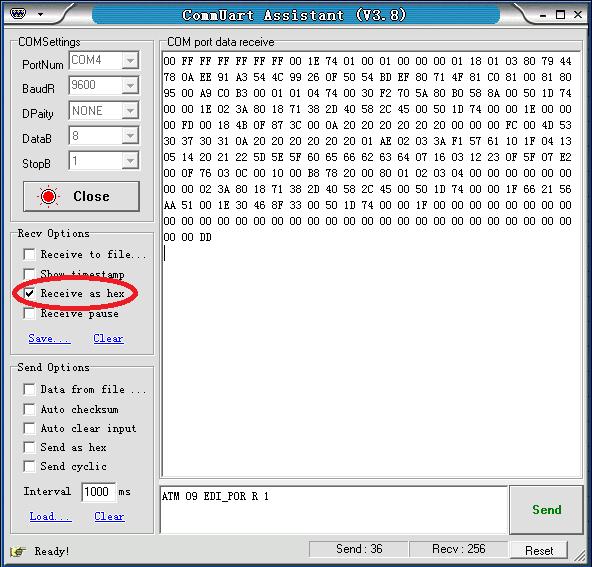
34 Read the EDID data: Send: ATM 09 EDI_POR R M M:1,2,3,4,5,6,7 (input No. 1-7) Feedback:( receive the EDID data as below) 00 FF FF FF FF FF FF 00 1E A EE 91 A3 54 4C F BD EF F 81 C A9 C0 B F2 70 5A 80 B0 58 8A D E 02 3A D C D E FD B 0F 87 3C 00 0A FC 00 4D A AE A F F D 5E 5F F 5F 07 E2 00 0F C B A D C D F AA E F D F DD 34 / 67
35 35 / 67
 N: 1, 2, 3, 4, 5, 6 (Inner preset EDID value No.")
36 Assign the inner EDID to appointed port: Inner EDID consists of two parts, Preset EDID and User Define EDID Assign preset EDID to certain port: Send: ATM 0B EDI_POR W M C N M:1,2,3,4,5,6,7 (input No. 1-7) N: 1, 2, 3, 4, 5, 6 (Inner preset EDID value No. 1-6) 36 / 67
 N: 1, 2, 3, 4, 5, 6, 7 (uploaded user define EDID No.")
37 Feedback:0B EDI_POR W M C N Assign user define EDID to certain input port: Send: ATM 0B EDI_POR W M E N M: 1, 2, 3, 4, 5, 6, 7 (input port No. 1-7) N: 1, 2, 3, 4, 5, 6, 7 (uploaded user define EDID No.1-7) Feedback:0B EDI_POR W M E N 37 / 67
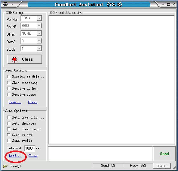
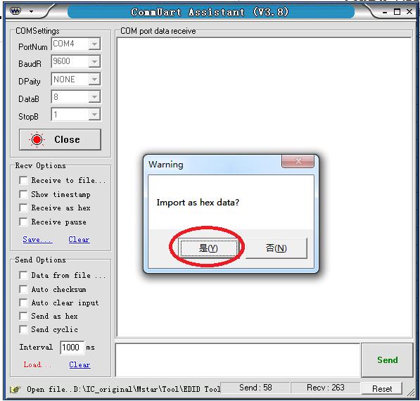
38 Upload EDID by RS232, LAN: Steps:1. Upload EDID to TEMP RAM Steps:2. Copy TEMP RAM EDID to the user define EDID Steps:3. Assign user define EDID to the input The whole EDID upload process procedure diagram is as below: 38 / 67
39 step1:upload EDID to TEMP RAM 39 / 67
40 40 / 67
41 After Step 1 upload, Feedback:EDID 256B Setp2:Copy TEMP RAM EDID to the user define EDID Send:ATM 09 EDI_EEP W M M: 1,2,3,4,5,6,7 (uploaded user define EDID No.1-7) Feedback: 09 EDI_EEP W M Notice:Please don t click the send as hex, as below 41 / 67
42 Advanced EDID management The HDBT- VTSC72-4K's advanced EDID management contains EDID assign, EDID upload and Download and EDID commands for managing the EDID from the seven input ports. 42 / 67
43 EDID Assign The HDBT- VTSC72-4K has built in six groups of fixed EDID and seven groups of user- defined EDID. These groups of EDID can be assigned to each input port. The current six groups of embedded EDID 1. 4K_8CH 2. 4K_2CH P_2CH P_8CH 5. VGA 6. (for DP) Therefore, the data for assigning EDID has two groups of commands: 1. Copy Built- in EDID to Port M: ATM 0B EDI_POR W M C N Copy the preset EDID N data in the program to the port M. 43 / 67
44 2. Copy EEPROM EDID to Port M: ATM 0B EDI_POR W M E N Copy the EDID data of the EEPROM N to the port M. For example: Send:ATM 0B EDI_POR W 1 C 1 Feedback:0B EDI_POR W 1 C 1 Send:ATM 0B EDI_POR W 2 E 2 Feedback:0B EDI_POR W 2 E 2 EDID upload and Download There is only one method for EDID uploading. The steps are shown as follows. 1. Send the 256 or 128 bytes of EDID data in hexadecimal format to the switcher via the serial or LAN ports, the switcher checks the data based on the format of EDID after receiving the data, and it responds EDID_256 or EDID_128 if no errors. 2. Send the following command to store the received EDID data in the EEPROM. Write EDID (EEPROM): ATM 09 EDI_EEP W n For example: Send:ATM 09 EDI_EEP W 1 Feedback:09 EDI_EEP W 1 3. Copy the EDID data to the related ports via the EDID assigning method. There are two methods to download the EDID data. One is to read the EDID data from the seven groups of data in the EEPROM. The other is to directly read the EDID data from the ports. 1. Read from the seven groups of data in the EEPROM. Read EDID(EEPROM): For example: Send:ATM 09 EDI_EEP R 1 Feedback:09 EDI_EEP R 1 ATM 09 EDI_EEP R n 2. Read the EDID data from the seven ports Read EDID from Port: ATM 09 EDI_POR R m For example: Send:ATM 09 EDI_POR R 1 44 / 67
45 Feedback:09 EDI_POR R bytes of EDID data will be sent back to the controller via RS232 or LAN ports. EDID Names There is a management method for EDID names. You can name the uploaded seven groups of EDID data in the EERPOM. They are EDID names write and read. 1. EDID Names Write Write EDID name (EEPROM): ATM 13 EDI_NAE W n XXXXXXXXXX Interior EDID n names write, the maximum length is 10 bytes. (If the names are less than 10 bytes, use the spaces). The characters include A ~ Z, a ~ z, 0 ~ 9, _, - For example: Send:ATM 13 EDI_NAE W 1 4K_8CH Feedback:13 EDI_NAE W 1 4K_8CH EDID Names Read Read EDID Name (EEPROM): ATM 09 EDI_NAE R n Interior EDID n names read For example: Send:ATM 09 EDI_NAE R 1 Feedback:4K_8CH EDID commands list Function Items Command Feedback Description 1 ATM 13 EDI_NAE W 1 4K2K_8CH_1 13 EDI_NAE W 1 4K2K_8CH_1 Interior EDID 1 name write ATM 13 EDI_NAE W 2 Write 2 13 EDI_NAE W 2 4K2K_8CH_2 Interior EDID 2 name write 4K2K_8CH_2 EDID ATM 13 EDI_NAE W 3 Name 3 13 EDI_NAE W 3 4K2K_8CH_3 Interior EDID 3 name write 4K2K_8CH_3 (EEPROM) ATM 13 EDI_NAE W EDI_NAE W 4 4K2K_8CH_4 Interior EDID 4 name write 4K2K_8CH_4 5 ATM 13 EDI_NAE W 5 13 EDI_NAE W 5 4K2K_8CH_5 Interior EDID 5 name write 45 / 67
46 6 7 4K2K_8CH_5 ATM 13 EDI_NAE W 6 4K2K_8CH_6 ATM 13 EDI_NAE W 7 4K2K_8CH_7 13 EDI_NAE W 6 4K2K_8CH_6 Interior EDID 6 name write EDI_NAE W 7 4K2K_8CH_7 Interior EDID 7 name write Read EDID Name (EEPROM) 1 ATM 09 EDI_NAE R 1 09 EDI_NAE R 1 Interior EDID 1 name read 2 ATM 09 EDI_NAE R 2 09 EDI_NAE R 2 Interior EDID 2 name read 3 ATM 09 EDI_NAE R 3 09 EDI_NAE R 3 Interior EDID 3 name read 4 ATM 09 EDI_NAE R 4 09 EDI_NAE R 4 Interior EDID 4 name read 5 ATM 09 EDI_NAE R 5 09 EDI_NAE R 5 Interior EDID 5 name read 6 ATM 09 EDI_NAE R 6 09 EDI_NAE R 6 Interior EDID 6 name read 7 ATM 09 EDI_NAE R 7 09 EDI_NAE R 7 Interior EDID 7 name read Write EDID (EEPROM) 1 ATM 09 EDI_EEP W 1 09 EDI_EEP W 1 2 ATM 09 EDI_EEP W 2 09 EDI_EEP W 2 3 ATM 09 EDI_EEP W 3 09 EDI_EEP W 3 4 ATM 09 EDI_EEP W 4 09 EDI_EEP W 4 5 ATM 09 EDI_EEP W 5 09 EDI_EEP W 5 6 ATM 09 EDI_EEP W 6 09 EDI_EEP W 6 7 ATM 09 EDI_EEP W 7 09 EDI_EEP W 7 Write EDID of the RAM into the EERPOM 1 Write EDID of the RAM into the EERPOM 2 Write EDID of the RAM into the EERPOM 3 Write EDID of the RAM into the EERPOM 4 Write EDID of the RAM into the EERPOM 5 Write EDID of the RAM into the EERPOM 6 Write EDID of the RAM into the EERPOM 7 Read EDID (EEPROM) 1 ATM 09 EDI_EEP R 1 Read EDID of the EEPROM 1 2 ATM 09 EDI_EEP R 2 Read EDID of the EEPROM 2 3 ATM 09 EDI_EEP R 3 Read EDID of the EEPROM 3 4 ATM 09 EDI_EEP R 4 Read EDID of the EEPROM 4 5 ATM 09 EDI_EEP R 5 Read EDID of the EEPROM 5 6 ATM 09 EDI_EEP R 6 Read EDID of the EEPROM 6 7 ATM 09 EDI_EEP R 7 Read EDID of the EEPROM 7 Copy Preset EDID to Port_1 1 ATM 0B EDI_POR W 1 C 1 0B EDI_POR W 1 C 1 Copy the preset EDID 1 in the program to port 1 2 ATM 0B EDI_POR W 1 C 2 0B EDI_POR W 1 C 2 Copy the preset EDID 2 in the program to port 1 3 ATM 0B EDI_POR W 1 C 3 0B EDI_POR W 1 C 3 Copy the preset EDID 3 in the program to port 1 4 ATM 0B EDI_POR W 1 C 4 0B EDI_POR W 1 C 4 Copy the preset EDID 4 in the 46 / 67
47 5 ATM 0B EDI_POR W 1 C 5 0B EDI_POR W 1 C 5 6 ATM 0B EDI_POR W 1 C 6 0B EDI_POR W 1 C 6 program to port 1 Copy the preset EDID 5 in the program to port 1 Copy the preset EDID 6 in the program to port 1 Copy EEPROM EDID to Port_1 1 ATM 0B EDI_POR W 1 E 1 0B EDI_POR W 1 E 1 2 ATM 0B EDI_POR W 1 E 2 0B EDI_POR W 1 E 2 3 ATM 0B EDI_POR W 1 E 3 0B EDI_POR W 1 E 3 4 ATM 0B EDI_POR W 1 E 4 0B EDI_POR W 1 E 4 5 ATM 0B EDI_POR W 1 E 5 0B EDI_POR W 1 E 5 6 ATM 0B EDI_POR W 1 E 6 0B EDI_POR W 1 E 6 7 ATM 0B EDI_POR W 1 E 7 0B EDI_POR W 1 E 7 Copy the EDID of the EEPROM 1 to port 1 Copy the EDID of the EEPROM 2 to port 1 Copy the EDID of the EEPROM 3 to port 1 Copy the EDID of the EEPROM 4 to port 1 Copy the EDID of the EEPROM 5 to port 1 Copy the EDID of the EEPROM 6 to port 1 Copy the EDID of the EEPROM 7 to port 1 Copy Preset EDID to Port_2 1 ATM 0B EDI_POR W 2 C 1 0B EDI_POR W 2 C 1 2 ATM 0B EDI_POR W 2 C 2 0B EDI_POR W 2 C 2 3 ATM 0B EDI_POR W 2 C 3 0B EDI_POR W 2 C 3 4 ATM 0B EDI_POR W 2 C 4 0B EDI_POR W 2 C 4 5 ATM 0B EDI_POR W 2 C 5 0B EDI_POR W 2 C 5 6 ATM 0B EDI_POR W 2 C 6 0B EDI_POR W 2 C 6 Copy the preset EDID 1 in the program to port 2 Copy the preset EDID 2 in the program to port 2 Copy the preset EDID 3 in the program to port 2 Copy the preset EDID 4 in the program to port 2 Copy the preset EDID 5 in the program to port 2 Copy the preset EDID 6 in the program to port 2 Copy EEPROM EDID to Port_2 1 ATM 0B EDI_POR W 2 E 1 0B EDI_POR W 2 E 1 2 ATM 0B EDI_POR W 2 E 2 0B EDI_POR W 2 E 2 3 ATM 0B EDI_POR W 2 E 3 0B EDI_POR W 2 E 3 4 ATM 0B EDI_POR W 2 E 4 0B EDI_POR W 2 E 4 5 ATM 0B EDI_POR W 2 E 5 0B EDI_POR W 2 E 5 Copy the EDID of the EEPROM 1 to port 2 Copy the EDID of the EEPROM 2 to port 2 Copy the EDID of the EEPROM 3 to port 2 Copy the EDID of the EEPROM 4 to port 2 Copy the EDID of the EEPROM 5 to port 2 47 / 67
48 6 ATM 0B EDI_POR W 2 E 6 0B EDI_POR W 2 E 6 7 ATM 0B EDI_POR W 2 E 7 0B EDI_POR W 2 E 7 Copy the EDID of the EEPROM 6 to port 2 Copy the EDID of the EEPROM 7 to port 2 Copy Preset EDID to Port_3 1 ATM 0B EDI_POR W 3 C 1 0B EDI_POR W 3 C 1 2 ATM 0B EDI_POR W 3 C 2 0B EDI_POR W 3 C 2 3 ATM 0B EDI_POR W 3 C 3 0B EDI_POR W 3 C 3 4 ATM 0B EDI_POR W 3 C 4 0B EDI_POR W 3 C 4 5 ATM 0B EDI_POR W 3 C 5 0B EDI_POR W 3 C 5 6 ATM 0B EDI_POR W 3 C 6 0B EDI_POR W 3 C 6 Copy the preset EDID 1 in the program to port 3 Copy the preset EDID 2 in the program to port 3 Copy the preset EDID 3 in the program to port 3 Copy the preset EDID 4 in the program to port 3 Copy the preset EDID 5 in the program to port 3 Copy the preset EDID 6 in the program to port 3 Copy EEPROM EDID to Port_3 1 ATM 0B EDI_POR W 3 E 1 0B EDI_POR W 3 E 1 2 ATM 0B EDI_POR W 3 E 2 0B EDI_POR W 3 E 2 3 ATM 0B EDI_POR W 3 E 3 0B EDI_POR W 3 E 3 4 ATM 0B EDI_POR W 3 E 4 0B EDI_POR W 3 E 4 5 ATM 0B EDI_POR W 3 E 5 0B EDI_POR W 3 E 5 6 ATM 0B EDI_POR W 3 E 6 0B EDI_POR W 3 E 6 7 ATM 0B EDI_POR W 3 E 7 0B EDI_POR W 3 E 7 Copy the EDID of the EEPROM 1 to port 3 Copy the EDID of the EEPROM 2 to port 3 Copy the EDID of the EEPROM 3 to port 3 Copy the EDID of the EEPROM 4 to port 3 Copy the EDID of the EEPROM 5 to port 3 Copy the EDID of the EEPROM 6 to port 3 Copy the EDID of the EEPROM 7 to port 3 Copy Preset EDID to Port_4 1 ATM 0B EDI_POR W 4 C 1 0B EDI_POR W 4 C 1 Copy the preset EDID 1 in the program to port 4 2 ATM 0B EDI_POR W 4 C 2 0B EDI_POR W 4 C 2 Copy the preset EDID 2 in the program to port 4 3 ATM 0B EDI_POR W 4 C 3 0B EDI_POR W 4 C 3 Copy the preset EDID 3 in the program to port 4 4 ATM 0B EDI_POR W 4 C 4 0B EDI_POR W 4 C 4 Copy the preset EDID 4 in the program to port 4 5 ATM 0B EDI_POR W 4 C 5 0B EDI_POR W 4 C 5 Copy the preset EDID 5 in the program to port 4 6 ATM 0B EDI_POR W 4 C 6 0B EDI_POR W 4 C 6 Copy the preset EDID 6 in the 48 / 67
49 program to port 4 Copy EEPROM EDID to Port_4 1 ATM 0B EDI_POR W 4 E 1 0B EDI_POR W 4 E 1 ATM 0B EDI_POR W 4 E 2 2 0B EDI_POR W 4 E 2 ATM 0B EDI_POR W 4 E 3 3 0B EDI_POR W 4 E 3 ATM 0B EDI_POR W 4 E 4 4 0B EDI_POR W 4 E 4 ATM 0B EDI_POR W 4 E 5 5 0B EDI_POR W 4 E 5 ATM 0B EDI_POR W 4 E 6 6 0B EDI_POR W 4 E 6 ATM 0B EDI_POR W 4 E 7 7 0B EDI_POR W 4 E 7 Copy the EDID in the EEPROM 1 to port 4 Copy the EDID in the EEPROM 2 to port 4 Copy the EDID in the EEPROM 3 to port 4 Copy the EDID in the EEPROM 4 to port 4 Copy the EDID in the EEPROM 5 to port 4 Copy the EDID in the EEPROM 6 to port 4 Copy the EDID in the EEPROM 7 to port 4 Copy Preset EDID to Port_5 1 ATM 0B EDI_POR W 5 C 1 0B EDI_POR W 5 C 1 2 ATM 0B EDI_POR W 5 C 2 0B EDI_POR W 5 C 2 3 ATM 0B EDI_POR W 5 C 3 0B EDI_POR W 5 C 3 4 ATM 0B EDI_POR W 5 C 4 0B EDI_POR W 5 C 4 5 ATM 0B EDI_POR W 5 C 5 0B EDI_POR W 5 C 5 6 ATM 0B EDI_POR W 5 C 6 0B EDI_POR W 5 C 6 Copy the preset EDID 1 in the program to port 5 Copy the preset EDID 2 in the program to port 5 Copy the preset EDID 3 in the program to port 5 Copy the preset EDID 4 in the program to port 5 Copy the preset EDID 5 in the program to port 5 Copy the preset EDID 6 in the program to port 5 Copy EEPROM EDID to Port_5 1 ATM 0B EDI_POR W 5 E 1 0B EDI_POR W 5 E 1 2 ATM 0B EDI_POR W 5 E 2 0B EDI_POR W 5 E 2 3 ATM 0B EDI_POR W 5 E 3 0B EDI_POR W 5 E 3 4 ATM 0B EDI_POR W 5 E 4 0B EDI_POR W 5 E 4 5 ATM 0B EDI_POR W 5 E 5 0B EDI_POR W 5 E 5 6 ATM 0B EDI_POR W 5 E 6 0B EDI_POR W 5 E 6 7 ATM 0B EDI_POR W 5 E 7 0B EDI_POR W 5 E 7 Copy the EDID of the EEPROM 1 to port 5 Copy the EDID of the EEPROM 2 to port 5 Copy the EDID of the EEPROM 3 to port 5 Copy the EDID of the EEPROM 4 to port 5 Copy the EDID of the EEPROM 5 to port 5 Copy the EDID of the EEPROM 6 to port 5 Copy the EDID of the EEPROM 7 to port 5 49 / 67
50 Copy Preset EDID to Port_6 1 ATM 0B EDI_POR W 6 C 1 0B EDI_POR W 6 C 1 2 ATM 0B EDI_POR W 6 C 2 0B EDI_POR W 6 C 2 3 ATM 0B EDI_POR W 6 C 3 0B EDI_POR W 6 C 3 4 ATM 0B EDI_POR W 6 C 4 0B EDI_POR W 6 C 4 5 ATM 0B EDI_POR W 6 C 5 0B EDI_POR W 6 C 5 6 ATM 0B EDI_POR W 6 C 5 0B EDI_POR W 6 C 6 Copy the preset EDID 1 in the program to port 6 Copy the preset EDID 2 in the program to port 6 Copy the preset EDID 3 in the program to port 6 Copy the preset EDID 4 in the program to port 6 Copy the preset EDID 5 in the program to port 6 Copy the preset EDID 6 in the program to port 6 Copy EEPROM EDID to Port_6 1 ATM 0B EDI_POR W 6 E 1 0B EDI_POR W 6 E 1 2 ATM 0B EDI_POR W 6 E 2 0B EDI_POR W 6 E 2 3 ATM 0B EDI_POR W 6 E 3 0B EDI_POR W 6 E 3 4 ATM 0B EDI_POR W 6 E 4 0B EDI_POR W 6 E 4 5 ATM 0B EDI_POR W 6 E 5 0B EDI_POR W 6 E 5 6 ATM 0B EDI_POR W 6 E 6 0B EDI_POR W 6 E 6 7 ATM 0B EDI_POR W 6 E 7 0B EDI_POR W 6 E 7 Copy the EDID of the EEPROM 1 to port 6 Copy the EDID of the EEPROM 2 to port 6 Copy the EDID of the EEPROM 3 to port 6 Copy the EDID of the EEPROM 4 to port 6 Copy the EDID of the EEPROM 5 to port 6 Copy the EDID of the EEPROM 6 to port 6 Copy the EDID of the EEPROM 7 to port 6 Copy Preset EDID to Port_7 1 ATM 0B EDI_POR W 7 C 1 0B EDI_POR W 7 C 1 2 ATM 0B EDI_POR W 7 C 2 0B EDI_POR W 7 C 2 3 ATM 0B EDI_POR W 7 C 3 0B EDI_POR W 7 C 3 4 ATM 0B EDI_POR W 7 C 4 0B EDI_POR W 7 C 4 5 ATM 0B EDI_POR W 7 C 5 0B EDI_POR W 7 C 5 6 ATM 0B EDI_POR W 7 C 6 0B EDI_POR W 7 C 6 Copy the preset EDID 1 in the program to port 7 Copy the preset EDID 2 in the program to port 7 Copy the preset EDID 3 in the program to port 7 Copy the preset EDID 4 in the program to port 7 Copy the preset EDID 5 in the program to port 7 Copy the preset EDID 6 in the program to port 7 Copy EEPROM 1 ATM 0B EDI_POR W 7 E 1 0B EDI_POR W 7 E 1 Copy the EDID of the EEPROM 1 to port 7 50 / 67
51 EDID to Port_7 2 ATM 0B EDI_POR W 7 E 2 0B EDI_POR W 7 E 2 3 ATM 0B EDI_POR W 7 E 3 0B EDI_POR W 7 E 3 4 ATM 0B EDI_POR W 7 E 4 0B EDI_POR W 7 E 4 5 ATM 0B EDI_POR W 7 E 5 0B EDI_POR W 7 E 5 6 ATM 0B EDI_POR W 7 E 6 0B EDI_POR W 7 E 6 7 ATM 0B EDI_POR W 7 E 7 0B EDI_POR W 7 E 7 Copy the EDID of the EEPROM 2 to port 7 Copy the EDID of the EEPROM 3 to port 7 Copy the EDID of the EEPROM 4 to port 7 Copy the EDID of the EEPROM 5 to port 7 Copy the EDID of the EEPROM 6 to port 7 Copy the EDID of the EEPROM 7 to port 7 Read EDID from Port Read EDID of input#1 Read EDID of input#2 Read EDID of input#3 Read EDID of input#4 Read EDID of input#5 Read EDID of input#6 Read EDID of input#7 ATM 09 EDI_POR R 1 09 EDI_POR R 1 Read EDID from input port 1 ATM 09 EDI_POR R 2 09 EDI_POR R 2 Read EDID from input port 2 ATM 09 EDI_POR R 3 09 EDI_POR R 3 Read EDID from input port 3 ATM 09 EDI_POR R 4 09 EDI_POR R 4 Read EDID from input port 4 ATM 09 EDI_POR R 5 09 EDI_POR R 5 Read EDID from input port 5 ATM 09 EDI_POR R 6 09 EDI_POR R 6 Read EDID from input port 6 ATM 09 EDI_POR R 7 09 EDI_POR R 7 Read EDID from input port 7 EDID copy Copy EDID from ATM 09 EDI_CPY 1 1 copy the EDID of output 1 and output#1 To 09 EDI_CPY 1 1 assigned it onto the input 1 Input#1 Copy EDID from ATM 09 EDI_CPY 1 2 copy the EDID of output 1 and output#1 To 09 EDI_CPY 1 2 assigned it onto the input 2 Input#1 Copy EDID from ATM 09 EDI_CPY 1 3 copy the EDID of output 1 and output#1 To 09 EDI_CPY 1 3 assigned it onto the input 3 Input#1 Copy EDID from ATM 09 EDI_CPY 1 4 copy the EDID of output 1 and output#1 To 09 EDI_CPY 1 4 assigned it onto the input 4 Input#1 Copy EDID from ATM 09 EDI_CPY 1 5 copy the EDID of output 1 and output#1 To 09 EDI_CPY 1 5 assigned it onto the input 5 Input#1 Copy EDID from ATM 09 EDI_CPY EDI_CPY 1 6 copy the EDID of output 1 and 51 / 67

52 output#1 To assigned it onto the input 6 Input#1 Copy EDID from output#1 To Input#1 ATM 09 EDI_CPY EDI_CPY 1 7 copy the EDID of output 1 and assigned it onto the input 7 WEB Setting The Switcher can be controlled via Web browser, which contains home screen, general settings and advanced settings. After the cables are connected (to LAN network and to your sources and display), the IP address is obtained as soon as you connect to LAN and will be able to see that on your Display OSD. Please punch in that IP address on your Web browser. You will see a GUI like below. And now the switcher can be controlled. For more information about how to obtain the IP address, see the chapter IP Setting above. For example, the obtained IP address is and port number is 23. Input in the address bar of the web browser. Click General and Advanced to access their pages. 52 / 67

53 General Settings Contain the following options. 1. Screen Layout Selection 2. Video Input Selection 3. Layout/ Ratio 4. Audio Input Selection 5. Audio Volume Setting 6. Audio Input Config. 7. Output Timing Screen Layout Selection 53 / 67
54 Single: single window; Double: double windows; TRIPLE: triple windows; Quadruple: quadruple windows. Select the related parameters, and click Submit to make the changes take effect. Video Input Selection Video inputs W1~W4 correspond to the video inputs of the four windows. Video selection ranges from 1 to 7, corresponding to the seven video inputs. Select the related parameters, and click Submit to make the changes take effect. Ration 54 / 67
55 Normal: Set the picture in the window as the original aspect ratio Full: Set the picture in the window to fill the entire window 16:9: Set the picture in Window 1 as the 16:9 aspect ratio 4:3: Set the picture in Window 1 as the 4:3 aspect ratio Select the related parameters, and click Submit to make the changes take effect. Audio Input Audio input selection ranges from 1 to 7, corresponding to the seven audio inputs. Select the related parameters, and click Submit to make the changes take effect. Audio Volume: 55 / 67
56 Output volume ranges from 0 to 10. O is mute, and 10 is the maximum volume. Select the related parameters, and click Submit to make the changes take effect. Output Timing: HDMI output resolution selection: AUTO (auto adjustment of the output resolution based on the EDID of the display device), 4Kx2K@30Hz, 1920x1080@60Hz, 1280x720@60Hz, 1920x1200@60Hz, 1600x1200@60Hz, 1280x800@60Hz, and 1024x768@60Hz. Select the related parameters, and click Submit to make the changes take effect. Advanced Settings 56 / 67
57 Contain the following options: 1. Power Switch Selection 2. Power Saving Selection 3. Audio Mute Selection 4. Audio Delay Selection 5. Auto Position Setting 6. Restore to default Setting 7. Series Baud rate 8. Audio OSD 9. Video OSD 10. FW version information Power Switch Selection HDBT- VTSC72-4K's power management: ON: When it's Power Off, set the device to power on. When it's Power On, set the device to stand by. Select the related parameters, and click Submit to make the changes take effect. 57 / 67
58 Power Saving Selection To save power, when no signal is input in all the windows, it enters the status of auto setting the standby time. Time options range from 0 min to 60 min. It's recommended that you use 0 min, 5 min, 10 min, 15 min, 30 min and 60 min. 0 is off, meaning turning off this function. Select the related parameters, and click Submit to make the changes take effect. Audio Mute Selection Audio output mute setting. OFF is turning off mute, outputting the audio normally. On is enabling the mute without outputting the audio. At the same time, OSD prompts the related icons. Select the related parameters, and click Submit to make the changes take effect. 58 / 67

59 Audio Delay Selection Audio output time- delay selection: 0~10. 0 is turning off the time- delay function. Select the related parameters, and click Submit to make the changes take effect. Auto Position Setting When VGA is used as an input, perform this function to automatically adjust the VGA picture. Adjustment parameters contain Horizontal Position, Vertical Position, Clock and Phase. At the same time, OSD prompts the related information (Auto Adjust). Click Submit to perform the settings. 59 / 67
60 Restore to default Setting Restore to the factory default, and click Submit to perform the settings. Serial Baud Rate Setting For Serial Baud rate setting. It's recommended that you use Select the related parameters, and click Submit to make the changes take effect. Audio OSD 60 / 67
61 For Audio OSD, select on/off and click Submit to make the changes take effect. It s possible to turn off all relative audio OSD, including Audio Mute, and Volume etc. Video OSD For Video OSD, select on/off and click Submit to make the changes take effect. It s used to turn off all relative video OSD, including source input, source resolution, signal indication, alert indication etc. FW information It includes the Unit Firmware version number, and the Web GUI version number. 61 / 67


62 EDID Contain the following options: 1. EDID Copy 2. EDID Upload 3. EDID Download 62 / 67


63 EDID Copy Select the EDID from six factory preset EDID package, seven custom EDID or HDMI output EDID for each input port, and click the Submit to take it into effect. EDID Upload For EDID Upload, user could upload a prepared EDID file from local pc. Click the Choose File to find a certain EDID file from local PC and select which custom EDID package to upload it. Then click Submit to take into effect. Once upload the new EDID file to the same custom EDID package, the old EDID file will be replaced. EDID Download Right- click each button and click save target/link as to start download the relative stored EDID file, from EDID of HDMI Output (The connected display device), seven input EDID package, or seven custom EDID package. 63 / 67
 and click the Submit to take into")

64 Network Contain the following options: 1. Network 2. Socket 3. Others: Network Default Setting Network Select DHCP enable or DHCP disable (Static IP) and click the Submit to take into effect. When DHCP enable is submitted, the unit will be assigned an IP address from the connecting network. When DHCP display is submitted, user could enter an IP address. Sockets Select TCP or UDP mode for the network communication, then click Submit to take into effect. Others: Network Default Setting 64 / 67
HDSC71D-4K 4K Multi-input 7x2 Presentation Scaler Switcher User Manual v0.5
 HDSC71D-4K 4K Multi-input 7x2 Presentation Scaler Switcher User Manual v0.5 1 The KanexPro HDSC71D-4K is a 7-input, 2-mirrored (HDMI & HDBaseT) output presentation scalerswitcher engineered to support
4K 7x1 Multiviewer Switcher (TEK MV71-4K & 79065) User Manual
 User Manual") 4K 7x1 Multiviewer Switcher (TEK MV71-4K 79064 & 79065) User Manual All Rights Reserved Revised July 1, 2015 1 / 49 Preface Read this user manual carefully before using this product. Pictures shown in
4K 7x1 Multiviewer Switcher (TEK MV71-4K 79064 & 79065) User Manual All Rights Reserved Revised July 1, 2015 1 / 49 Preface Read this user manual carefully before using this product. Pictures shown in
4K 7x1 Multi-format Presentation Switcher DV-MFSS-71
 4K 7x1 Multi-format Presentation Switcher DV-MFSS-71 Based on firmware revision 1.11 and FSR1.0.0.L 244 Bergen Blvd Woodland Park NJ 07424 973-785-4347 www.fsrinc.com 43091 LIT1557 2 PROPRIETARY INFORMATION
DVI-3580a. 4K MultiViewer Switcher / Scaler. Quick Start Guide. Introduction
 Quick Start Guide DVI-580a K MultiViewer Switcher / Scaler Introduction Presentation Powerhouse The DVI-580a is a high-performance K MultiViewer, Presentation Switcher and Scaler. This unit is an ideal
Instruction Manual 1T-MV K Multiviewer
 Instruction Manual 1T-MV-8474 4K Multiviewer Table of Contents Liability Statement...4 Safety Precautions... 5 Introduction... 6 Key Benefits... 7 Getting Started... 8 Front Panel... 8 Rear Panel... 9
Blackbird 4K 4x1 Scaler and Switch
 Blackbird 4K 4x1 Scaler and Switch P/N 31057 User's Manual CONTENTS SAFETY WARNINGS AND GUIDELINES... 3 INTRODUCTION... 4 FEATURES... 4 CUSTOMER SERVICE... 4 PACKAGE CONTENTS... 5 PRODUCT OVERVIEW... 5
Blackbird 4K HDBaseT Scaler and 2x1 Switch
 Blackbird 4K HDBaseT Scaler and 2x1 Switch P/N 31056 User's Manual CONTENTS SAFETY WARNINGS AND GUIDELINES... 3 INTRODUCTION... 4 FEATURES... 4 CUSTOMER SERVICE... 5 PACKAGE CONTENTS... 5 PRODUCT OVERVIEW...
CSW-HDBT300M. Multi-Input Switcher to HDMI with HDBaseT up to 330ft Transmitter & Receiver. Operation Manual
 CSW-HDBT300M Multi-Input Switcher to HDMI with HDBaseT up to 330ft Transmitter & Receiver Operation Manual 1.Introduction This machine is a high performance presentation scaler and switcher. It accepts
Website: Toll Free: [US]
![Website: Toll Free: [US]](/thumbs/86/93333879.jpg "Website: Toll Free: [US]") Operating Instructions Website: www.jtechdigital.com Toll Free: 1-888-610-2818[US] Email: Support@jtechdigital.com NexAV TM 4K@30Hz HDMI+VGA Wall Plate Extender 70M/40M NA-6000 SAFETY AND NOTICE The HDMI+VGA
Operating Instructions Website: www.jtechdigital.com Toll Free: 1-888-610-2818[US] Email: Support@jtechdigital.com NexAV TM 4K@30Hz HDMI+VGA Wall Plate Extender 70M/40M NA-6000 SAFETY AND NOTICE The HDMI+VGA
TECHNICAL SPECIFICATION
 Front View Back View Part Number: Page Number: 1 of 6 Introduction The is a multi-format switcher with 2 - HDMI, 1 - VGA, and 1 - Display Port inputs, and a single HDMI output. It supports multiple switching
LBC-PSW52. Link Bridge TM Presentation Scaling Switch with 5 Inputs and Two Mirrored Outputs
 LBC-PSW52 Link Bridge TM Presentation Scaling Switch with 5 Inputs and Two Mirrored Outputs BCI reserves the right to make changes to the products described herein without prior notice or consent. No liability
User manual. P4K-HUL4E1 4K UHD HDMI & USB Over IP Extender P4K-HUL4E1-P 4K UDH HDMI & USB Over IP Extender with PoE
 User manual P4K-HUL4E1 4K UHD HDMI & USB Over IP Extender P4K-HUL4E1-P 4K UDH HDMI & USB Over IP Extender with PoE P4K-HRSUL4E1 / P4K- LHRSU1E4 P4K-HRSUL4E1-P/ P4K-LHRSU1E4-P Partilink Technology Co.,
SM-4X4-4K18GBA-LC. 4x4 HDMI2.0 Matrix Support YUV4:4:4, 18Gbps, HDR. Operating Instruction
 SM-4X4-4K18GBA-LC 4x4 HDMI2.0 Matrix Support 4K@60hz YUV4:4:4, 18Gbps, HDR Operating Instruction 1 Thank you for purchasing this product. For optimum performance and safety, please read these instructions
4K HDBase-T Matrix Kit
 4K HDBase-T Matrix Kit Simple set up guide HDMI8X8MC Important Safety Notice Thank you for purchasing this Antiference HDMI distribution product. Please read the following instructions carefully and retain
HDBaseT Lite 4x6 HDMI Matrix of 2 HDMI and 4 CAT5e/6/7 (PoE 60m) Outputs - # 15228
 Outputs - # 15228") HDBaseT Lite 4x6 HDMI Matrix of 2 HDMI and 4 CAT5e/6/7 (PoE 60m) Outputs - # 15228 Operation Manual Introduction Applications The 4 by 6 Matrix allows HDMI signal from any of its four sources to be routed
HDBaseT Lite 4x6 HDMI Matrix of 2 HDMI and 4 CAT5e/6/7 (PoE 60m) Outputs - # 15228 Operation Manual Introduction Applications The 4 by 6 Matrix allows HDMI signal from any of its four sources to be routed
MONOPRICE. Blackbird 4K HDBaseT Wall Plate Scaler Transmitter. User's Manual P/N 21816
 MONOPRICE Blackbird 4K HDBaseT Wall Plate Scaler Transmitter P/N 21816 User's Manual CONTENTS SAFETY WARNINGS AND GUIDELINES... 3 INTRODUCTION... 3 FEATURES... 4 CUSTOMER SERVICE... 4 PACKAGE CONTENTS...
VS-88UT All in One Presentation System with 8x8 4K60 4:2:0 HDMI/HDBaseT 2.0 Matrix Switching, Master Room Controller, PoE & Power Amplifier
 VS-88UT All in One Presentation System with 8x8 4K60 4:2:0 HDMI/HDBaseT 2.0 Matrix Switching, Master Room Controller, PoE & Power Amplifier HDMI Speakers Ethernet - RJ-45 HDBaseT 4K/60 UHD (4:2:0) VS 88UT
AVG-UHD4K-44 V2. Features
 Features The AVG-UHD4K-44 V2 is a professional 4K 4x4 HDMI Matrix Switcher with 4 HDMI inputs, 4 HDMI outputs, 4 SPDIF audio outputs and 4 analogue audio outputs. This unit is designed to switch HDMI 2.0
8 8 HDMI over CAT5e/6/7 Matrix - ID# 15122
 8 8 HDMI over CAT5e/6/7 Matrix - ID# 15122 Operation Manual Introduction Features Applications The HDBaseT Lite 8 by 8 HDMI Matrix over CAT5e/6/7 supports the transmission of video (resolutions up to 1080p
Omega 4K/UHD Scaler for HDBaseT and HDMI with USB
 Omega 4K/UHD Scaler for HDBaseT and HDMI with USB The Atlona is an HDBaseT receiver and 4K/UHD scaler with a local HDMI input. Part of the Omega Series of integration products for modern AV communications
CH-1529TX/RX HDCP 2.2 & HDMI2.0 Extender with OAR / Audio Insertion
 CH-1529TX/RX HDCP 2.2 & HDMI2.0 Extender with OAR / Audio Insertion Operation Manual DISCLAIMERS The information in this manual has been carefully checked and is believed to be accurate. Cypress Technology
HDBaseT 8x8 HDMI Matrix over CAT5e/6/7 with LAN Serving Operation Manual
 HDBaseT 8x8 HDMI Matrix over CAT5e/6/7 with LAN Serving Operation Manual DISCLAIMERS The information in this manual has been carefully checked and is believed to be accurate. Network Technologies Inc
PLEASE READ THIS PRODUCT MANUAL CAREFULLY BEFORE USING THIS PRODUCT.
 Features The AVG-FMM16 is a high-performance seamless AV modular matrix, providing 12 flexible PCIE slots for single HDMI / HDBaseT / DVI / SDI / VGA input/output cards and 4 fixed slots for output signal
Installation Guide AT-HDR-H2H-44M
 4K HDR 4 4 HDMI to HDMI Matrix Switcher The Atlona is a 4 4 HDMI matrix switcher for high dynamic range (HDR) formats. It is HDCP 2.2 compliant and supports 4K/UHD video @ 60 Hz with 4:4:4 chroma sampling,
INT-HD52 Quick Install Guide
 INT-HD52 Quick Install Guide This guide is for quick installation only. For complete owners manual go to www.libav.com or use a QR reader to access the manual via QR code below. Scan QR Code with your
CMLUX-44E. 4 by 4 HDMI V1.3 Matrix. Operation Manual CMLUX-44E
 CMLUX-E by HDMI V1.3 Matrix Operation Manual CMLUX-E Revision History Version No. Date Summary of Change V1 20090521 Preliminary Release V2 20100805 Adding RS-232 Setting V3 20100923 HDMI Cable Distance
HDMI Displayport VGA 3D-2D Scaler w/3d Bypass ID # 786
 HDMI Displayport VGA 3D-2D Scaler w/3d Bypass ID # 786 Operation Manual Introduction This high performance video processor which allows 3D movies to be watched on a 2D display. With HDMI, DisplayPort and
Installation Guide. 4K/UHD Two-Output HDMI to HDBaseT Distribution Amplifier AT-UHD-CAT-2. Package Contents
 4K/UHD Two-Output HDMI to HDBaseT Distribution Amplifier Installation Guide The Atlona is a 4K/UHD HDMI to HDBaseT distribution amplifier featuring passthrough HDMI input connections, two HDBaseT outputs,
SM-4X4-4K18GB-LC. Low Cost 4K HDMI Video Matrix Switch: 4x4. Operating Instruction
 SM-4X4-4K18GB-LC Low Cost 4K HDMI Video Matrix Switch: 4x4 Operating Instruction 1 Thank you for purchasing this product. For optimum performance and safety, please read these instructions carefully before
LBC-HDV-T LINK BRIDGE TM HDBASET HDMI/DISPLAYPORT/VGA TRANSMISSION SYSTEM
 LBC-HDV-T LINK BRIDGE TM HDBASET HDMI/DISPLAYPORT/VGA TRANSMISSION SYSTEM BCI reserves the right to make changes to the products described herein without prior notice or consent. No liability is assumed
Omega 4K / UHD Three-Input Switcher for HDMI and USB-C with HDBaseT and HDMI Outputs
 Omega 4K / UHD Three-Input Switcher for HDMI and USB-C with HDBaseT and HDMI Outputs Installation Guide The Atlona is a 3 1 switcher and HDBaseT transmitter with HDMI and USB-C inputs. It features mirrored
Omega 4K HDR 3x2 Matrix Switcher for HDMI and USB-C with HDMI Outputs
 Omega 4K HDR x Matrix Switcher for HDMI and USB-C with HDMI Outputs The Atlona is a matrix switcher with HDMI and USB-C inputs, and HDMI outputs. It is HDCP. compliant and supports 4K HDR and 4K/60 4:4:4
HDTVMT0404VL1 User Manual
 HDTVMT0404VL1 User Manual HDTVMT0404VL1 User Manual Contact: support@hdtvsupply.com 1 Thank you for purchasing this product. For optimum performance and safety, please read these instructions carefully
4x4 4K HDBaseT Matrix HMXL44AB. User Manual
 4x4 4K HDBaseT Matrix HMXL44AB User Manual Contents Thank you for purchasing this product. For optimum performance and safety, please read these instructions carefully before connecting, operating or adjusting
MultiTasker. MultiTasker Design Guide
 MultiTasker Design Guide MultiTasker ETHERNET 00-40V -6A Doc. #: 66-00-00 www.altinex.com Copyright 06 MultiTasker manufacturing process Product projections Customer places an order Enclosures and Cards
CMLUX-44E. 4 by 4 HDMI V1.3 Matrix. Operation Manual CMLUX-44E
 CMLUX-44E 4 by 4 HDMI V1.3 Matrix Operation Manual CMLUX-44E Revision History Version No. Date Summary of Change V1 20090521 Preliminary Release V2 20100805 Adding RS-232 Setting V3 20100923 HDMI Cable
HDMI to HDBaseT Scaler with Audio Output - ID# 15461
 HDMI to HDBaseT Scaler with Audio Output - ID# 15461 Operation Manual Introduction This HDMI to HDBaseT Scaler can send uncompressed audio/video along with control, Ethernet, and extra audio data over
OR-H44E. 4 by 4 HDMI V1.3 Matrix. Operation Manual OR-H44E
 OR-HE by HDMI V1.3 Matrix Operation Manual OR-HE Revision History Version No. Date Summary of Change V1 20090521 Preliminary Release Precautions Failure to follow the precautions described below may cause
CSC K UHD + HDMI to HDMI Scaler with EDID Management
 CSC-6013 4K UHD + HDMI to HDMI Scaler with EDID Management Operation Manual DISCLAIMERS The information in this manual has been carefully checked and is believed to be accurate. Cypress Technology assumes
User Manual MP-SC-5TDS. Compact Scaler Switcher (with PoH) All Rights Reserved. Version: MP-SC-5TDS_2016V1.0
 All Rights Reserved. Version: MP-SC-5TDS_2016V1.0") User Manual MP-SC-5TDS Compact Scaler Switcher (with PoH) All Rights Reserved Version: MP-SC-5TDS_2016V1.0 Compact Scaler Switcher (with PoH) Preface Read this user manual carefully before using this product.
User Manual MP-SC-5TDS Compact Scaler Switcher (with PoH) All Rights Reserved Version: MP-SC-5TDS_2016V1.0 Compact Scaler Switcher (with PoH) Preface Read this user manual carefully before using this product.
HSM-88-4K. 4K 8X8 HDMI Matrix Switch
 User s Manual HSM-88-4K 4K 8X8 HDMI Matrix Switch Supports 4K UHD resolution HDCP 2.2 and 1.4 compliant with EDID Management Fast-Switch Technology RS-232, IP, IR and Front panel Control with Status LCD
CMLUX-44E. 4 by 4 HDMI V1.3 Matrix. Operation Manual CMLUX-44E
 CMLUX-44E 4 by 4 HDMI V1. Matrix Operation Manual CMLUX-44E Revision History Version No. Date Summary of Change V1 20090521 Preliminary Release Precautions Failure to follow the precautions described below
1-chip DLP Laser Projector with High Brightness LX-MH502Z
 1-chip DLP Laser Projector with High Brightness LX-MH502Z Product Outline The LX-MH502Z is a compact and lightweight 4K UHD DLP laser projector capable of projecting high-resolution 4K images, making it
KD-SX440WP. Operating Instructions
 Rev 0 Jan 2018 KD-SX440WP 4K 2x1 HDMI/VGA Wall-Plate Switcher, Scaler & Extender with HDBaseT Output (Includes KIT Wall-Plate Tx/Rx 4K/70meters 1080P/100meters) Operating Instructions Key Digital, led
SM-8X8-4K18GB-LC. Low-Cost 4K HDMI Video Matrix Switch: 8x8. Operating Instruction
 SM-8X8-4K18GB-LC Low-Cost 4K HDMI Video Matrix Switch: 8x8 Operating Instruction 1 Thank you for purchasing this product. For optimum performance and safety, please read these instructions carefully before
SC35.MX HDMI 18Gbps Over HDBaseT Matrix VER 1.1
 SC35.MX44 4 4 HDMI 8Gbps Over HDBaseT Matrix VER. Thank you for purchasing this product For optimum performance and safety, please read these instructions carefully before connecting, operating or adjusting
Stereo / Mono. Audio Power Amplifier W. Introduction. Applications
 Amplifier - 120 W Introduction The Atlona Gain 120 () is a compact power amplifier designed for low or high impedance applications. A mode selector switch allows the Gain 120 to deliver two channels of
User Manual TPSW-4K. 4 1 Multi-Format Scaler Switcher. All Rights Reserved. Version: TPSW-4K_2016V1.0
 User Manual TPSW-4K 4 1 Multi-Format Scaler Switcher All Rights Reserved Version: TPSW-4K_2016V1.0 Preface Read this user manual carefully before using this product. Pictures shown in this manual is for
Installation Guide. Stereo / Mono Audio Power Amplifier - 60 Watts AT-GAIN-60. Package Contents
 Stereo / Mono Audio Power Amplifier - 60 Watts Installation Guide The Atlona Gain 60 () is a compact power amplifier designed for low or high impedance applications. A mode selector switch allows the Gain
CPLUS-V11PE8 4K UHD + HDMI Audio Extractor (LPCM 7.1)
") CPLUS-V11PE8 4K UHD + HDMI Audio Extractor (LPCM 7.1) Operation Manual DISCLAIMERS The information in this manual has been carefully checked and is believed to be accurate. Cypress Technology assumes
CPLUS-V11PE8 4K UHD + HDMI Audio Extractor (LPCM 7.1) Operation Manual DISCLAIMERS The information in this manual has been carefully checked and is believed to be accurate. Cypress Technology assumes
HSM-44-BX. 4K 4X4 HDMI Matrix Switch with HDBaseT and HDMI Outputs
 User s Manual HSM-44-BX 4K 4X4 HDMI Matrix Switch with HDBaseT and HDMI Outputs Supports 4K UHD resolution HDCP 2.2 and 1.4 compliant with EDID Management Extends HDMI, IR, RS-232, IP, and Power over HDBaseT
AVG-TMX44PRO Features:
 The TMX44PRO is a professional 4K 4x4 HDBaseT Matrix Switcher that accommodates 4 HDMI IN, 4 HDBT with 2 mirrored HDMI outputs, 4 Digital Audio outputs and 4 Analogue audio outputs. HDMI inputs are selected
Operation Manual CLUX-210S
 x10 HDMI 1.3 Splitter Operation Manual CLUX-10S TABLE OF CONTENTS 1. Introduction... 1. Features... 1 3. Operation Controls and Functions... 3.1 Front Panel... 3. Rear Panel... 3 4. Remote Control... 4
Kramer Electronics, Ltd. USER MANUAL. Model: TP Channel UXGA/Audio/RS-232 to CAT 5 Transmitter
 Kramer Electronics, Ltd. USER MANUAL Model: TP-185 8 Channel UXGA/Audio/RS-232 to CAT 5 Transmitter Contents Contents 1 Introduction 1 2 Getting Started 1 2.1 Quick Start 2 3 Overview 3 3.1 Shielded Twisted
FLEX MATRIX. Complete Guide to the Intelix Flex Matrix Switcher Series
 FLEX MATRIX Complete Guide to the Intelix Flex Matrix Switcher Series FLEX MATRIX // REAL VALUE FOR THE PRO AV INSTALLER Flex some signal distribution muscle with Liberty s full line of Intelix Flex Matrices!
Edition:2A ODM- 88. DVI Matrix Router USER MANUAL
 Edition:2A ODM- 88 DVI Matrix Router USER MANUAL ODM-88 Manual Page 2 ODM-88 Manual Page 3 Table of Contents 1 Introduction and Installation. 6 1.1 Key features... 6 1.2 ODM-88 Shipping Content... 6 1.3
DM-MD8X1-4K-C/HD-MD8X1-4K 4K Scaling Auto-Switchers. Supplemental Guide Crestron Electronics, Inc.
 DM-MD8X1-4K-C/HD-MD8X1-4K 4K Scaling Auto-Switchers Supplemental Guide Crestron Electronics, Inc. The product warranty can be found at www.crestron.com/legal/sales-terms-conditions-warranties. The specific
4x4 HDMI2.0 Matrix Support YUV4:4:4, 18Gbps, HDR. Operating Instruction
 4x4 HDMI2.0 Matrix Support 4K@60hz YUV4:4:4, 18Gbps, HDR Operating Instruction 1 Thank you for purchasing this product. For optimum performance and safety, please read these instructions carefully before
Atlona products will be preconfigured for plug-n-play compatibility with Bang & Olufsen systems
 Atlona and B&O ATLONA / BANG & OLUFSEN GLOBAL PARTNERSHIP Atlona products will be preconfigured for plug-n-play compatibility with Bang & Olufsen systems Bang & Olufsen dealers can purchase Atlona products
4K-WALL HDMI/DVI Video Wall Controller and 4x4 Switch Matrix. User Manual
 4K-WALL HDMI/DVI Video Wall Controller and 4x4 Switch Matrix. User Manual Integrated 2x2 Video Wall Controller and 4x4 Port HDMI, Real Time Switch Matrix with On Screen Display Control & No Software Required.
AVG-UHS41 DA. Features
 Features The AVG-UHS41 DA is an ultrathin auto switcher with four HDMI inputs and one HDMI output. This switcher supports HDMI video resolutions up to 4Kx2K@60Hz 4:4:4 HDR and multichannel audio. There
CMLUX-4H4CAT. 4 by 4 HDMI V1.3 over CAT 5 Matrix. Operation Manual CMLUX-4H4CAT
 CMLUX-4H4CAT 4 by 4 HDMI V1.3 over CAT 5 Matrix Operation Manual CMLUX-4H4CAT Revision History Version No. Date Summary of Change V1 20090610 Preliminary Release Precautions Failure to follow the precautions
5x1 HDMI / HDBT Multimedia Presentation Switch Installation Guide
 5x1 HDMI / HDBT Multimedia Presentation Switch 500435 MuxLab Inc. 2015 94-000798-A / SE-000798-A SAFETY PRECAUTIONS To insure the best from the product, please read all instructions carefully before using
Model DVS-2A 2-Port DVI Switch with Audio, Serial Control & Long Cable Equalization
 Hall Research Technologies, Inc. Model DVS-2A 2-Port DVI Switch with Audio, Serial Control & Long Cable Equalization UMA1127 Rev B Copyright 2007. Hall Research Technologies, Inc. All rights 1163 Warner
ZU500T / ZH500T / ZW500T / ZX500 / ZU500TST / ZX500TST
 ZU500T / ZH500T / ZW500T / ZX500 / ZU500TST / ZX500TST Contents Product Description Cabinet Dimensions Installation Requirements Image Size & Projection Distance Back & Control Panel PC Control Codes LAN
User Manual VL Compact Scaler Switcher (with PoH)
") User Manual VL120028 Preface Read this user manual carefully before using this product. Pictures shown in this manual is for reference only, different model and specifications are subject to real product.
User Manual VL120028 Preface Read this user manual carefully before using this product. Pictures shown in this manual is for reference only, different model and specifications are subject to real product.
EXT-HD-MVSL-441. User Manual. Release A3
 MultiviewAudio 3GSDI Seamless Embedder Switcher EXT-HD-MVSL-441 User Manual Release A3 4x1 Multiview Seamless Switcher for HDMI Important Safety Instructions 1. Read these instructions. 2. Keep these instructions.
XT-HDBT-MX44-4K-KIT. Introduction. User Manual. Key Features XT-HDBT-MX44-4K-KIT USER MANUAL
 XT-HDBT-MX44-4K-KIT User Manual Introduction Our XT-HDBT-MX44-4K-KIT 4x4 HDBaseT Matrix offers unprecedented performance and value for the custom installation market. The XT- HDBT-MX44-4K-KIT is a 4K HDCP
PU-O4H4C. v1.3 HDMI 4x4 Matrix with built in HDMI over CAT6 outputs OPERATION MANUAL
 PU-O4H4C v1.3 HDMI 4x4 Matrix with built in HDMI over CAT6 outputs OPERATION MANUAL Table of Contents 1. Introduction 1 2. Features 1 3. Package Contents 1 4. Operation Controls and Functions 2 4.1 Front
CA-HT-sc-BIGONE-TX. Manual
 CA-HT-sc-BIGONE-TX Manual Table of contents 1. Introduction...6 1.1 Introduction to the Scaler Switcher... 6 1.2 Features... 6 1.3 Package List... 7 2. Panel Description...8 2.1 Front Panel... 8 2.2 Rear
HDSC61D-4K. 6-Input Collaboration Switcher & Scaler with. 4K HDMI Output. All Rights Reserved. Version: HDSC61D-4K_2015V1.1
 HDSC61D-4K 6-Input Collaboration Switcher & Scaler with 4K HDMI Output All Rights Reserved Version: HDSC61D-4K_2015V1.1 Preface Read this user manual carefully before using this product. Pictures shown
KRAMER ELECTRONICS LTD. USER MANUAL MODEL: VS-41H 4x1 HDMI Switcher. P/N: Rev 7
 KRAMER ELECTRONICS LTD. USER MANUAL MODEL: VS-41H 4x1 HDMI Switcher P/N: 2900-000667 Rev 7 Contents 1 Introduction 1 2 Getting Started 2 2.1 Achieving the Best Performance 2 2.2 Safety Instructions 3
Installation Guide AT-HDVS-SC-RX
 4K/UHD Scaler for HDBaseT and with Video Wall Processing The Atlona is an HDBaseT receiver and 4K/UHD scaler with a local input. It receives HDBaseT for video output up to 4K/30 4:4:4, plus embedded audio,
SDV-FTX/FRX. Ultra-HDMI (4K/60) over Fiber extender OPERATION MANUAL
 over Fiber extender OPERATION MANUAL") SDV-FTX/FRX Ultra-HDMI (4K/60) over Fiber extender OPERATION MANUAL DISCLAIMERS The information in this manual has been carefully checked and is believed to be accurate. CYP (UK) Ltd assumes no responsibility
SDV-FTX/FRX Ultra-HDMI (4K/60) over Fiber extender OPERATION MANUAL DISCLAIMERS The information in this manual has been carefully checked and is believed to be accurate. CYP (UK) Ltd assumes no responsibility
4K HDMI & USB/AUDIO/RS232/IR CAT5e Extender ITEM NO: SE150HX-4K HDMI & USB/ Audio/RS232/IR CAT5e Extender
 4K HDMI & USB/AUDIO/RS232/IR CAT5e Extender ITEM NO: SE150HX-4K HDMI & USB/ Audio/RS232/IR CAT5e Extender The SE150HX-4K HDMI & USB with Analog audio, RS232, and IR CAT5e extender design for extend all
Installation Guide AT-OME-EX-RX
 Omega 4K/UHD HDMI Over HDBaseT Receiver with USB, Control, and PoE The Atlona is an HDBaseT receiver for video up to 4K/60 4:2:0, plus embedded audio, control, Ethernet, and USB over distances up to 330
Blackbird 4K HDBaseT 4x4 HDMI Matrix
 Blackbird 4K HDBaseT 4x4 HDMI Matrix P/N 27841 User's Manual CONTENTS SAFETY WARNINGS AND GUIDELINES... 4 INTRODUCTION... 5 FEATURES... 6 CUSTOMER SERVICE... 6 PACKAGE CONTENTS... 7 PRODUCT OVERVIEW...
PS-5IN-SCALER_2016V1.3
 USER MANUAL PS-5IN-SCALER Compact Scaler Switcher (with PoH) All Rights Reserved Version: PS-5IN-SCALER_2016V1.3 Preface Read this user manual carefully before using this product. Pictures shown in this
Quick Start Guide. Support 3D. Features
 Quick Start Guide HDMI Matrix 4x CAT5e/6 Extender Features Incorporates HD Base-T technology. Any Four Sources to Any Four Displays,Each port supports HDMI or DVI inputs. The four outputs are all include
4 x 4 HDMI Matrix Switcher With HDBaseT PoC Outputs
 Installation Guide 4 x 4 HDMI Matrix Switcher With HDBaseT PoC Outputs 4 HDMI in to 4 HDBaseT + 2 mirrored HDMI out SY Electronics Ltd, Unit 7, Worrall Street, Salford, Greater Manchester, M5 4TH, United
HDMI over IP Extender HP100FT HDMI KVM, USB, RS232, IR over IP - Transmitter HP100FR HDMI KVM, USB, RS232, IR over IP Receiver
 HDMI over IP Extender HP100FT HDMI KVM, USB, RS232, IR over IP - Transmitter HP100FR HDMI KVM, USB, RS232, IR over IP Receiver HP100FT-front view HP100FR-front view HP100FT-rear view HP100FR-rear view
KRAMER ELECTRONICS LTD. USER MANUAL MODEL: VS-161H 16x1 HDMI Switcher. P/N: Rev 6
 KRAMER ELECTRONICS LTD. USER MANUAL MODEL: VS-161H 16x1 HDMI Switcher P/N: 2900-000665 Rev 6 Contents 1 Introduction 1 2 Getting Started 2 2.1 Achieving the Best Performance 2 3 Overview 3 3.1 About HDMI
Operation Manual CLUX-210S
 x0 HDMI.3 Splitter Operation Manual CLUX-0S TABLE OF CONTENTS. Introduction.... Features... 3. Operation Controls and Functions... 3. Front Panel... 3. Rear Panel... 3. Remote Control... 5. RS-3 Remote
KRAMER ELECTRONICS LTD. USER MANUAL MODEL: VP-553 Presentation Switcher/Scaler. P/N: Rev 6
 KRAMER ELECTRONICS LTD. USER MANUAL MODEL: VP-553 Presentation Switcher/Scaler P/N: 2900-300326 Rev 6 Contents 1 Introduction 1 2 Getting Started 2 2.1 Achieving the Best Performance 2 2.2 Safety Instructions
SM-8X8-C64KR-POE-HDBT
 SM-8X8-CKR-POE-HDBT KK 8x8 HDMI Matrix over CAT5e// Operation Manual SAFETY PRECAUTIONS Please read all instructions before attempting to unpack, install or operate this equipment and before connecting
JPEG K60 4:4:4 UHD Video Over IP Encoder with PoE, KVM, AES-67 NMX-ENC-N2412A (FGN2412A-SA), Stand Alone NMX-ENC-N2412A-C (FGN2412A-CD), Card
, Stand Alone NMX-ENC-N2412A-C (FGN2412A-CD), Card") DATA SHEET JPEG 2000 4K60 4:4:4 UHD Video Over IP Encoder with PoE, KVM, AES-67 NMX-ENC-N2412A (FGN2412A-SA), Stand Alone NMX-ENC-N2412A-C (FGN2412A-CD), Card Overview The NMX-ENC-N2412A is the first low-latency
DATA SHEET JPEG 2000 4K60 4:4:4 UHD Video Over IP Encoder with PoE, KVM, AES-67 NMX-ENC-N2412A (FGN2412A-SA), Stand Alone NMX-ENC-N2412A-C (FGN2412A-CD), Card Overview The NMX-ENC-N2412A is the first low-latency
KRAMER ELECTRONICS LTD. USER MANUAL MODEL: VP-553xl Presentation Switcher/Scaler. P/N: Rev 2
 KRAMER ELECTRONICS LTD. USER MANUAL MODEL: VP-553xl Presentation Switcher/Scaler P/N: 2900-300421 Rev 2 Contents 1 Introduction 1 2 Getting Started 2 2.1 Achieving the Best Performance 2 2.2 Safety Instructions
4x4 4K HDMI 2.0 Matrix - HDCP 2.2 MX44AB-V2. User Manual
 4x4 4K HDMI 2.0 Matrix - HDCP 2.2 MX44AB-V2 User Manual Thank you for purchasing this product. For optimum performance and safety, please read these instructions carefully before connecting, operating
CH-1602TX & CH-1602RX HDMI over HDBaseT Transmitter and Receiver with Optical Audio Return (OAR)
") CH-1602TX & CH-1602RX HDMI over HDBaseT Transmitter and Receiver with Optical Audio Return (OAR) Operation Manual DISCLAIMERS The information in this manual has been carefully checked and is believed
CH-1602TX & CH-1602RX HDMI over HDBaseT Transmitter and Receiver with Optical Audio Return (OAR) Operation Manual DISCLAIMERS The information in this manual has been carefully checked and is believed
AVG-HD402PR. Features
 Features The AVG-HD402PR uses HDBaseT technology to deliver HDMI signal with a maximum transmission distance up to 60 meters with CAT5e/CAT6 cable. Supports Full HD: Delivers resolutions including 800x600@60Hz,
8x8 HDMI2.0 Matrix Support YUV4:4:4, 18Gbps, HDR. Operating Instruction
 8x8 HDMI2.0 Matrix Support 4K@60hz YUV4:4:4, 18Gbps, HDR Operating Instruction 1 Thank you for purchasing this product. For optimum performance and safety, please read these instructions carefully before
UHD2-140 Owner s Manual
 UHD2-140 Owner s Manual 1 x 4 HDMI 2.0 Distribution Amplifier PureLink TM 535 East Crescent Avenue Ramsey, NJ 07446, USA Tel: 201.488.3232 Fax: 201.621.6118 E-mail: info@purelinkav.com www.purelinkav.com
HDBaseT 4 4 HDMI Matrix over CAT5e/6/7 Cable with PoE # 15281
 HDBaseT 4 4 HDMI Matrix over CAT5e/6/7 Cable with PoE # 15281 Operation Manual Introduction Features Applications The HDBaseT 4 by 4 HDMI Matrix over CAT5e/6/7 supports the transmission of video (resolutions
CMSI-424L 4 x 4 HDMI Matrix over 4 CAT5e/6/7 with 2 HDMI outputs
 CMSI-L x HDMI Matrix over CAT5e/6/7 with HDMI outputs Operation Manual DISCLAIMERS The information in this manual has been carefully checked and is believed to be accurate. Cypress Technology assumes
HDMX42-18G 4K UHD+ 4 2 HDMI
 4K UHD+ 4 2 HDMI Matrix 4K/60Hz 4x2 HDMI 2.0 Matrix Switcher All Rights Reserved MPN: HDMX42-18G SAFETY PRECAUTIONS Please read all instructions before attempting to unpack, install or operate this equipment
MONOPRICE. Blackbird 4K 5x1 HDMI Presentation Switch. User's Manual P/N 21906
 MONOPRICE Blackbird 4K 5x1 HDMI Presentation Switch P/N 21906 User's Manual CONTENTS SAFETY WARNINGS AND GUIDELINES... 4 INTRODUCTION... 4 FEATURES... 5 CUSTOMER SERVICE... 5 PACKAGE CONTENTS... 6 PRODUCT
4 by 4 HDMI V1.3 Matrix ID #735
 4 by 4 HDMI V1.3 Matrix ID #735 Operation Manual Introduction While HDMI products are getting more and more popular in the market people usually have more than one HDMI devices and sources in one place.
KRAMER ELECTRONICS LTD. USER MANUAL MODEL: VS-808TP 8x8 Twisted Pair Matrix Switcher. P/N: Rev 1
 KRAMER ELECTRONICS LTD. USER MANUAL MODEL: VS-808TP 8x8 Twisted Pair Matrix Switcher P/N: 2900-300147 Rev 1 Contents 1 Introduction 1 2 Getting Started 2 2.1 Achieving the Best Performance 2 2.2 Using
SURGE PROTECTION DEVICE RECOMMENDED
 4x4 HDMI2.0 Matrix Support 4K@60hz YUV4:4:4, 18Gbps, HDR Operating Instruction 1 Thank you for purchasing this product. For optimum performance and safety, please read these instructions carefully before
AVG-UHD4K-44. Features
 Features The AVG-UHD4K-44 4x4 HDMI Matrix Switcher is a professional 4x4 HDMI Matrix Switcher that is capable of receiving up to 4 HDMI 2.0 & HDCP 2.2 compliant signals and outputting 4 HDMI 1.4 & HDCP