F & SC Serial Access Control Station. Installation Guide
|
|
|
- Thomas McCormick
- 6 years ago
- Views:
Transcription
1 F & SC Serial Access Control Station Installation Guide
2 About this Guide The F&SC Access Control Station User guide is designed to provide information to install the F& SC serial Access Control Station, for operation and configuration, please refer to the corresponding user s manual. Not all function these guides introduce available in combination, all is option. About your machine function, please consult our company technical personnel or the sales personnel. Information in this document is subject to change without notice.
3 Contents 1 Before Installing Notice about installing System Configuration The illustration of system construction The sketch map of communication Installation Fixing mounting plate Connect with peripheral equipment Door Sensor Release Button Alarm Conntion with lock Ethernet connection Connection with RS Connection with RS Wiegand output Power connection Connect with external Weigend reader Fixing Access Control Station Fastening Access Control Station Others Reset Anti-dismantle button Cable doorbell...25 SC Series rechargeable battery specifications...26
4 1 Before Installing 1.1 Notice about installing Access Control Station is a mass-produced product. It strictly tested comply with the standard of China, U.S.A, and EU. This file contains important information. It is better for you to read it carefully prior to use. If you ignore it, the incorrect installation may cause the unit damage. Although we could do our best to offer you service, the neglect to the file could cause unwanted cost for you. 1. Before installation, please make sure the power is cut off, because it is very dangerous if the power is on. The short circuit of power cable may cause the core parts damage. 2. All exposed part of connection wire end cannot be exceeded 5mm to prevent the bared wire accidental connection which leads to machine break down. And also suggest using different color cable to connect. 3. In the place where the static is strong or in winter, please connect the grounding firstly, in order to prevent the instant mass static damage the machine. 4. Connect power supply with device in the last for the wiring connection. If you find any unusual thing occur, please firstly cut off the power, then go to examine. Keep in mind: wiring operation under power on will lead to machine sudden damage; we are not liable for damages and trouble due to such operation
5 5. The height to mount device is about meter 6. After installation, please take off protection film on the fingerprint sensor to get best recognize result. 7. After installation finish, when go to test the exit-door button, please keep a personal in the outside, because sometimes the accidental issue can bring on you are not able to go outside. 8. Our equipment offer an automatically function, please after the installing finish. Run the auto-test function to confirm the installation finish. 9.We recommend using above the 12V/3A direct-current supply for ZK software s access control device, electricity lock better to powered by 12VDC, and no more than 1.5 A electric current At this time, the electric current of supply should be above1a than lock power. If the parameter of lock power surpasses this scope, please connect technical personnel. If the power had not met above requests, it possibly causes to be unable normally to drive the electricity lock, even damage the device. 10. Before device to be connected please read and always follow "Quick connect Guide" closely. Because the wrong wiring will cause the core block and sensor to burn out, insult in device to break down, at this cause ZK Software is not liable for any damages and trouble. 11. If the space between power adapters and device is too long, please do not use the twisted-pair or other type ferrules for the power wire. When the power wire is choused, you should consider attenuation of voltage, which has passed long distance transfer. 12. Please use specialized RS485 cable and the RS232/485 converter with power to hookup the network, the bus structure apply to connect - 2 -
6 with each device. When a long cable is used to transfer signal, it is need to connect a matching resistance to receiver, and its value is 120Ώ. 13. Other more details items; please see also the user manual, the operating instructions and the appendix and so on
7 2 System Configuration 2.1 The illustration of system construction - 4 -


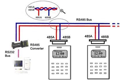
8 2.2 The sketch map of communication Access Control Station directly connects with PC through RS232 or TCP/IP Access Control Station connects with PC through RS485 network 3 Access Control Station connects with PC through TCP/IP network
9 3.Installation 3.1 Fixing mounting plate 1 Take out a Access Control Station,dismantle the screw between machine body and mounting plate until it is out, see figure (1). 2 Carefully take up the bottom of mounting plate, see figure (2), push it up, see figure (3), then take away the mounting plate. 3 Determine the position of mounting plate on the wall. The Access Control Station should be mounted on the external wall of the door approximately 1400mm from the ground to the unit bottom. After the position is determined, you could drill a hole (18mm*20mm) for cable out, see below figure shadowed part. 4 Make the hole of mounting plate meet the drilled hole on the wall, Use the screw to fix it on the wall, (for the details please see following figure) 5 after installation, please make sure the mounting plate is reliable, fasten, not loosed
10 3.2 Connect with peripheral equipment Caution: Do not to connect peripheral equipment before the power of the device is cut down, otherwise it is possible to damage the device badly. Please follow instruction to connect peripheral equipment 1 Door sensor connection(sensor, GND) 2 Exit-button connection(button GND) 3 Alarm connection(alarm+, Alarm-) 4 Door lock connection(nc, COM, NO ) 5 Ethernet connection( RJ45-1, RJ45-2, RJ45-3,RJ45-4) 6 RS232 connection(232rx, 232TX, GND ) 7 RS485 connection(485a,485b ) 8 Wiegand output connection(wd0,wd1,gnd ) 9 Cable Bell (Bell+, Bell-) 10 Power connection (GND, +12V) Cable socket
11 Alarm - Alarm + NC COM NO Button GND Sensor Bell+ Bell- GND +12V The definition of socket without Wiegand input RJ45-1 RJ45-2 RJ45-3 RJ45-6 WD0 WD1 GND 232RX 232 TX GND 485 A 485 B BEEP GLED RLED WD1 WD0 GND +12V The definition of socket with Wiegand input Jump - 8 -
12 3.2.1 Door Sensor The door sensor is used to detect the door open-close status, Access Control Station can monitor if the door has been unauthorized open through the door sensor, at this time it can output a alarm signal, moreover, Access Control Station can trigger prompt warning if after surpassing a timed period, the door still open Release Button The exit-button is installed for in-door operation. When the switch of the button is close, the door will open. The distance is approximately 1400mm from ground to exit-button bottom. Make sure that the exit-button position is to align correct, upright and the connection is accurate and reliable. (Unused exposed end of cable should be cut off, and use insulating tape to wrap it.) Pay attention to electromagnetic disturbance. (For example: The light switch, the computer and so on) Alarm Access Control Station alarm output is a switch signal,it is able to connect with simple alarm by serial circuit, it also apply to top grade alarm and monitor system as a trigger signal( this machine alarm function only support 12 VDC Warner) - 9 -
13 3.2.4 Conntion with lock The way of installing door lock depends on the type of lock and local condition. Internal resistor, which comes from long distance transfer, should be taken into consideration when selecting the cable of electric power. The door lock should be installed reliable and stable. Ensure the wiring is correct. For the strike lock and electromagnetic lock, you should pay attention to positive and negative terminal connection. The unused bare end of wire should be cut off and use insulating tape to wrap it. The delay time of strike lock is adjustable according to different conditions. Normally close (NC), under normal state the equipment keeps up closed, if force the equipment open, the circuit cut off, brings out the state change. Normally Open (NO), under normally state the circuit is cut off, if force the equipment open, the circuit will be closed, and produce a state
14 change. Power Ground(GND),Current loop ground Input terminal of door sensor(sensor,gnd )the input port of door sensor accepts the signal which come from normally closed contact to detect the door opening and closing state, when the door is in closed, the contact keep in closed state, if the door is opened by someone, the circuit break, thus bring out state change. If unauthorized user opens this door or opening time is too long, the controller will send alarm Input terminal of release door button(button, GND)The input port of release door button accepts the signal which come from normally opened contact to indicate that somebody want to go out, the input equipment such as action detector, press sensitivity floor board or exit-door button all serve as source to send signal,if nobody send out request to want to go out, the input keep disconnection, if somebody want to go out, they trigger release door button, the circuit is closed. Produce state change, the controller responded to the request, unlock and permit door serve as passage mode. Note:the process of performance to unlock door is control by relay, when you install door lock, there are two thing you must think about, -- safety and security, in other words, do you want which result that is if lose control of this door, the door is still in safety lost control but safety or if lose control of this door, the door still is security--- lost control but security Lost control but safety is that the power supply cut off (maybe the power supply is cut or the controller lose control of itself, the door will be open automatically, and permit everybody freely to pass in and out,
15 the door is not ability to be closed until the system power on, these type of doors are installed in the protective area which ensure everybody is able to pass in and out. One representative application of lost control but safety is to use electromagnetism lock, under normal power supply, the door is controlled by the controller, once the power supply break off, the electromagnetism lock will lose magnetism and does not take effect, the door become a passage mode Lost control but security is that the power supply cut off, the door will be locked automatically, do not permit external personal to come in, but permit internal personal go out, the door is not to be unlocked until the system power supply is in gear. Make sure that the door of lost control but security will be installed in the area, which needs to be protected through fair and foul. One representative application of lost control but security is to use electrical lock, if the power supply break off, the external personal is not able to open the door, but the internal person can open the by manual operation. In the following three cases, we recommend that fingerprint machine and lock be powered separately. 1) The working voltage of the lock is DC12V, but the current difference of the fingerprint machine and the lock doesn t exceed 1A. 2) The lock voltage is not DC12V. 3) The distance between lock and fingerprint machine is too far. 1 NC lock connection(access Control Station and lock power by one adapter together, Jump 2,3 pin closed)
16 Lock 2 NO lock connection (Access control Station and lock powered by one adapter together, Jump 2.3 pin closed). Lock
17 3 the output relay signal by Access control station, NC lock connection (Access Control Station and lock powered by independent adapters jump 1,2 closed) Lock Lock Power 4 the output relay signal by Access control station, NO lock connection ( Access Control station and lock powered by independent adapter
Access Control Station connects with PC through cross cable 2)Access Control")
18 Lock Power Lock Ethernet connection 1)Access Control Station connects with PC through cross cable 2)Access Control Station connects with PC through network and HUB to create a local network
, fully support 10Base-T and 100Base-TX. Plug1 Pin Pin Plug 2 TX+ 1 < > 3 RX+ TX- 2 < > 6 RX- - 16 -")
19 3) RJ45 plug wiring diagrams for Ethernet a) RJ45 plug standard b) Ethernet 10/100Base T Crossover Cable mostly apply to HUB and Switch,or directly connect two Ethernet terminals(not through HUB), fully support 10Base-T and 100Base-TX. Plug1 Pin Pin Plug 2 TX+ 1 < > 3 RX+ TX- 2 < > 6 RX
20 RX+ 3 < > 1 TX+ RX- 6 < > 2 TXc) Ethernet 10/100Base-T Straight Thru Cable Support 10Base-T and 100Base-TX,apply to connect with network card and HUB(or network outlet), sometime it is called (whips) Wiring standard Pin Color Pin Wiring standard TX+ 1 < white orange > 1 TX+ TX- 2 < Orange > 2 TX- RX+ 3 < white green > 3 RX+ 4 < Blue > 4 5 < Blue white > 5 RX- 6 < Green > 6 RX- 7 < White brown > 7 8 < Brown > Connection with RS232 The definition of PC connection with Access Control Station PC Serial Port Access Control Station serial port Pin2-Rxd Pin5-Txd Pin3-Txd Pin4-Txd Pin5-Gnd Pin6-Gnd
21 3.2.7 Connection with RS485 The definition of terminal connection Terminal Function Pin1-485A RS-485 communication + Pin2-485B RS-485 communication
22 - 19 -

23 3.2.8 Wiegand output Access Control Station provide standard Wiegand 26 output, which can be connected to most of access controllers, like the way of connecting with a ID reader or password keyboard. The distance from the controller to device cannot be more than 15 meter (if the signal must be transferred much further or there is a strong interference around, please adopt a Wiegand signal amplifier) Mote: no matter the device is powered by access controller or not, the ground ports of them have to be properly together to ensure the Wiegand transfer reliable Terminal Pin1-WD0 Pin2-WD1 Pin3-GND Function Output Wiegand data 0 signal Output Wiegand data 1 signal Ground

24 3.2.9 Power connection This device is powered by 12VDC. Its current is approximately 50mA in the ready work status and 400mA in the work status. The power is conducted along with the terminal; you can use the 12V-4A-supply adapter that is provided along with the device. The detail about connection is as follow. Terminal Pin1- GND Pin2- PWR Function Power negative Power positive The following figure is an example, which takes a provided power adapter to connect Connect with external Weigend reader Access control device whit the Weigand input function is able to connect with card reader, which is located in outdoor or indoor, control the door by the controller together, the cable which between access controller and external card reader is no more than 90 meter

25 3.3 Fixing Access Control Station 1 Confirm all connection plugs correctly. 2 Align back iron-plate of Access Control Station body to mounting plate properly, and push it up, see figure1, then push device backward, see figure 2. 3 Turn and tie up the screw bottom. After finishing installation, make ensure the body of device is fixed tightly
26 4. Fastening Access Control Station After all system installation finished, make a test and examine prior to power on, inspect whether the lock driver is OK or not, for more details, please see User Guide and Software Manual 1the green LED begins to glitter after power up. 2enter menu- Option- Auto-test. 3enter menu- User manage- User Enroll- Fingerprint Enroll,Enroll a fingerprint, and use the fingerprint to test access control system and door lock.. 4if there is no any problem. Please delete this enrolled fingerprint
27 5. Others 5.1 Reset Due to operation error or other accidence, which leads the machine not to work, you can restart machine through reset key. 1take a small tool which diameter is no more than 2mm. 2find reset mark of res on the left small hole on the bottom of device, see following figure. 3Use the tool plug into the hole refer to the picture on right, then plug out. The machine is able to restart. Reset key 5.2 Anti-dismantle button Anti-dismantle button is on middle of device, whose function is realized by back-cover pressing the anti-dismantle button. When the device is being dismantled, it will send an alarm signal through the terminal
28 5.3 Cable doorbell There is a key which is remark as icon( is used for doorbell. ) on the keypad, this key Door Bell Put the doorbell in the proper place, press the doorbell key on the device, please see circle marked, after the doorbell receive a signal, it will ring. Note:Because the terminal and key our provided is used for cable doorbell, must join the power into the electric round
29 SC Series rechargeable battery specifications specifications Model: MS621F Nominal voltage (V): 3 Charging voltage (standard charge voltage): 2.8V-3.3V (3.1V) Nominal capacity (mah): 5.5 Internal resistance (): 80 Standard charge and discharge current (ma): The largest discharge current (continuous) (ma): 0.25 Life cycle (times): 100% charge and discharge: 200; 20% charge and discharge: 1000 Size (mm): diameter: 6.8; Height: 2.1 Weight (g): 0.23 Features Discharge capacity 3.3 V-2.0V with the high voltage at the same time, you will receive a large discharge capacity. Charge and discharge cycles longυ life Under the 3.3 V-2.0V the charge and discharge conditions (discharge depth of 100%), can achieve more than 200 rounds of the charge and discharge. Excellence in the discharge A discharge to 0.0 V so far, can also show a stable discharge capacity
30 UL (Underwriters Laboratories Inc) specifications (UL File No.MH 15628) Application Mobile, office equipment, and other electronic equipment, sever as the standby power for clock functions of kinds of memory. dischargeν characteristics Charge: Max 0.1 ma/96 hours (rated current, rated voltage charging) Discharge: 25 μ A / cov = 2.0V (rated current discharge) Discharge characteristics Proposed rated voltage. Because of the charge current restrictions, the need to connect to the current limit resistance Nominal capacity: 3.3 V-2.0V, / FS products in the discharge capacity of 3.1 V-2.0V within the typical scope Internal resistance by the exchange value of Alternating Current The largest discharge current: the available capacity of about 50 percent, the current capacity of Maintain the minimum capacity of 50 percent The number of repeated charge 100% and 20% of the nominal capacity as the standard
31 Information in this document is subject to change without notice Printed in China
TFT screen Fingerprint Machine
 TFT screen Fingerprint Machine Installation Instruction V1.1 TFT screen Fingerprint Machine Installation Instruction Contents About this Guide The TFT screen Fingerprint Machine User guide is designed
Installation Instruction
 Installation Instruction Version: 3.1.1 Date: June 2010 About This Manual This document describes the installation guide and wiring instruction. Installation InstructionV3. 1.1 Contents 1. Before Installing...1
iclock Access control Installation
 iclock Access control Installation instruction Version: 6.0.1 Date: June 2010 About This Manual This document describes the 8 inches TFT iclock access control serials products installation guide and wiring
2.4 TFT Installation Instruction V TFT. Installation Instruction
 2.4 TFT Installation Instruction V1.0 2.4 TFT Installation Instruction Contents About this Guide The User guide is designed to provide information to install the 2.4TFT, for operation and configuration,
T&A Fingerprint machine
 Installation Guide series 2 V1.0 T&A Fingerprint machine Installation Guide series 2 Content 1. Before Installing... 1 1.1 Notice... 1 1.2 View of Operation Panel... 3 1.3 View of Power and Comm. Port...
TFT&U serials T&A Installation Instruction
 Version: 2.1 Date: Nov. 2009 About This Manual This document describes the TFT&U serials T&A Installation Instruction installation guide and wiring instruction. Content 1 Before Installing...1 1.1 Notice...1
F701. Installation Guide
 F701 Installation Guide F701installation_V1.1 Contents 1. Before Installing... 1 1.1 Notice... 1 1.2 Encasement list... 3 1.3 Other required equipment... 5 2. The illustration of system construction...
iface Series Installation Guide
 iface Series Installation Guide Version:1.0 Date:Sep 2009 About this Guide This guide provides actual installation instructions only. For information regarding user instructions, please refer to iface
F11 Installation Guide. Version: 1.0 Date: Jul. 2010
 F11 Installation Guide Version: 1.0 Date: Jul. 2010 Table of Contents Table of Contents 1. Before Installing... 1 1.1 Notice About Installing... 1 1.2 Operation Panel:... 3 2. System Configuration...
SCR100 User Manual. Version:1.1 Date:Dec 2009
 SCR100 User Manual Version:1.1 Date:Dec 2009 Introduction: This document mainly introduces the installations and connections of SCR100 products, and the brief operations about attendance software. Important
T&A Fingerprint machine. Installation Guide series 1
 T&A Fingerprint machine Installation Guide series 1 Installation Instruction V2.0 Contents 1. Before Installing... 1 1.1 Notice... 1 1.2 View of Operation Panel... 3 1.3 View of Power and Comm. Port...
SF200. Installation Guide & Quick Start Guide. 2 TFT AC Terminal Version: 1.0 Date: June 2014
 SF200 Installation Guide & Quick Start Guide 2 TFT AC Terminal Version: 1.0 Date: June 2014 All design and specification declared are subject to change without notice in advance. Contents Safety Precautions
F7_F707_F708 Installation Instruction V1.0 F7_F707_F708. Access Control Terminal. Installation Instructions
 F7_F707_F708 Access Control Terminal Installation Instructions Revised May 2008 About this Guide This guide provides installation instructions only. For information regarding actual operation and configuration
iclock serial Time & Attendance and Access Control Terminal Installation Instructions
 iclock serial Time & Attendance and Access Control Terminal Installation Instructions About this Guide This guide provides installation instructions only. For information regarding actual operation and
CM-110SK Standalone Keypad Installation Instructions
 CM-0SK Standalone Keypad Installation Instructions. Packing List Qty Name Remarks 2 2 Keypad User manual Screwdriver Wall plugs Self-tapping screws Torx screw 0.8 x 2.4 Φ(20 mm 60 mm) 0.24 x.2 Φ (6 mm
Single Door Standalone Access Control User Manual
 Single Door Standalone Access Control User Manual Reading this manual carefully before install and use the device 1. Packing List Name Quantity Remarks Keypad User manual Screw driver Rubber plug Self
Finger Vein Access Control device Quick Start Guide Version: 1.0 Date: June USB slot. USB slot
 Overview Fingerprint & Finger Vein Device Front Left Side: Finger Vein Device Touch screen Card reader Fingerprint reader Finger vein reader Finger vein sensor: During registration, after finger touches
QUICK START GUIDE. 2.4 Inch Finger Vein Terminal Time Attendance & Access Control
 QUICK START GUIDE 2.4 Inch Finger Vein Terminal Time Attendance & Access Control Version: 1.0 Date: Apr., 2017 1 2.4-Inch TFT LCD USB Storage Device Port Keypad& Card Reader Doorbell & LED Indicator Fingerprint
Digital Keypad Introduction
 K2 Digital Keypad Introduction The K02 uses the latest microprocessor technology to operate door strikes and security systems that require a momentary (timed) or latching dry contact closure. All programming
CV-110SPK Standalone Keypad/Prox Access Control Installation Instructions
 CV-110SPK Standalone Keypad/Prox Access Control Installation Instructions 1. Packing List Qty Name Remarks 1 1 1 2 2 1 Keypad User manual Screwdriver Wall plugs Self-tapping screws Torx screw 0.8 x 2.4
Standalone Keypad Access Control. User Manual. Please read the manual carefully before use this unit
 Standalone Keypad Access Control User Manual Please read the manual carefully before use this unit 1. Packing List Name Quantity Remarks Keypad 1 User manual 1 Screw driver 1 Φ20mm 60mm,Special for keypad
Standalone Keypad Access Control. User Manual. SS-TS2000 Size:120*80*25 mm
 Standalone Keypad Access Control User Manual SS-TS2000 Size:120*80*25 mm Please read the manual carefully before use this unit 1. Packing List Name Quantity Remarks Keypad 1 User manual 1 Screw driver
Safety Precautions How to place the finger Product Contents Product PIN Diagram Product Dimensions Cables and Connectors Installation of Back Plate
 www.zkaccess.com Safety Precautions How to place the finger Product Contents Product PIN Diagram Product Dimensions Cables and Connectors Installation of Back Plate Power Connection Ethernet Connection
Quick Start Guide. ProBio & ProFAC + ZKBioSecurity 3.0
 Quick Start Guide ProBio & ProFAC + ZKBioSecurity 3.0 CONTENT 1 Safety Precautions...2 On Using Face Recognition Device...3 Device Overview...5 Product Dimensions & Installation...6 Power Connection...7
Waterproof. Keypad/Reader/Controller
 Waterproof Keypad/Reader/Controller User Manual W1-C W3-C User manual 1. Packing List Name Quantity Remarks Digital Keypad-W1-C/W3-C 1 User manual 1 Screw driver 1 Rubber bungs 4 6*27mm, used for fixing
CV-550SPK V2 Waterproof Keypad/Reader/Controller Installation Instructions
 CV-550SPK V2 Waterproof Keypad/Reader/Controller Installation Instructions Packing List NAME MODEL/SIZE QTY Self tapping screw 0.15 x 1.06 (4mm 27 mm) Rubber plug 0.23 x 1.2 (6mm 30 mm) Star screw driver
Simple Card Reader for Door Access & Time Attendance System. User Guide
 Simple Card Reader for Door Access & Time Attendance System User Guide 3 CHAPTER 1 GETTING STARTED Viewing the User Guide in the Internet Included Accessories Included Printed Materials Activating m-kadex
AC-115 Compact Networked Single-Door Controller Hardware Installation and Programming
 AC-115 Compact Networked Single- Controller Hardware Installation and Programming Copyright 2013 by Rosslare. All rights reserved. This manual and the information contained herein are proprietary to REL,
H2i. s u p p o r f i n g e r t e c. c o m. H2i. Simple Fingerprint Door Access & Time Attendance System. User Guide
 H2i s u p p o r t @ f i n g e r t e c. c o m H2i Simple Fingerprint Door Access & Time Attendance System User Guide CONTENTS 3-4 Chapter 1 getting started Viewing the User Guide in the Internet Included
Installation Instructions (KF-2000)
") VERSION 2005. 10 Installation Instructions (KF-2000) Keico Hightech, Inc. Installation Instructions KF-2000 Keico Hightech Ace Twin Tower I 12 th FL 212-1, Guro-Dong, Guro-Gu Phone +82-2-853-9000 Fax +82-2-830-7809
VERSION 2005. 10 Installation Instructions (KF-2000) Keico Hightech, Inc. Installation Instructions KF-2000 Keico Hightech Ace Twin Tower I 12 th FL 212-1, Guro-Dong, Guro-Gu Phone +82-2-853-9000 Fax +82-2-830-7809
Two-door Access Controller
 Two-door Access Controller Quick Start Guide V1.0.0 Preface Overview This document elaborates on structure, installation, interface and wiring of two-door access controller. Symbol Definition The following
W Series. Color Screen Fingerprint & Card Time Attendance and Access Control W 1 W 2
 W Series Color Screen Fingerprint & Card Time Attendance and Access Control W 1 W 2 W1 & W2 Features * Standard 2.8-inch TFT LCD, 512MB Flash, industrial high speed CPU * Touch keypad & touch active sensor
HSY-S209 EM Metal waterproof access control system User Manual
 HSY-S209 EM Metal waterproof access control system User Manual Reading carefully before Install and use this manual 1. Product Profile The product is Contact-less inductive card Metal Password Access Controller,
Guangdong Be-tech Security Systems Limited. Elevator Control Manual Instruction. Version 2013 Page1 total 22
 Elevator Control Manual Instruction Version 2013 Page1 total 22 Content Guangdong Be-tech Security Systems Limited 1. Unit Dimensions... 3 1.1. Card reader board... 3 1.2. Relay board... 3 1.3. Relay box
QUICK START GUIDE. 2.4 Inch TFT Terminal Time Attendance & Access Control
 QUICK START GUIDE 2.4 Inch TFT Terminal Time Attendance & Access Control Safety Precautions The following precautions are to keep user safe and prevent any damage. Please read carefully before installation.
F6-Fingerprint. Access Control/Reader. User Manual. F6 - Simplified Instruction. (Master Code) # (Factory default:1234) Enter the Programming Mode
 # (Factory default:1234) Enter the Programming Mode") -Fingerprint Access Control/Reader Function Description Enter the Programming Mode - Simplified Instruction Operation (Factory default:1234) Change the Master Code Add Fingerprint User Add Card User Add
-Fingerprint Access Control/Reader Function Description Enter the Programming Mode - Simplified Instruction Operation (Factory default:1234) Change the Master Code Add Fingerprint User Add Card User Add
REX F-0-9 Standalone or Access Controller
 REX F-0-9 Standalone or Access Controller Power supply The controller need s external power supply to operate. The Spider W40 power supply is sufficient to power two controllers and two 12V electric strikes
WiFi Video Doorbell. User Manual
 WiFi Video Doorbell User Manual Introduction Content With Hisilicon Hi3518E processor and H.264 compression technology, this Wifi video intercom provides smooth realtime video transmission while keeps
USER MANUAL C5S110&120&140. Version: 1.1 Date: Apr., 2018
 USER MANUAL C5S110&120&140 Version: 1.1 Date: Apr., 2018 About This Manual This manual introduces C5S110/120/140 access control panel installation connection and user instructions. Contents 1 Safety Instructions...
GENERAL QUICK START GUIDE
 GENERAL QUICK START GUIDE 2.8InchPalm & Fingerprint Time Attendance & Access Terminal Version: 1.0 Date: May., 2017 Note: The picture and function presented in this manual are only for reference. The following
INSTALLATION GUIDE DM-20 English Version 1.10 EN DM20 V1.10A
 www.supremainc.com INSTALLATION GUIDE DM-20 English Version 1.10 EN 101.00.DM20 V1.10A Contents Safety Instructions... 3 Components... 4 Front Side... 5 Installation Example... 6 Dimensions... 7 Installation...
C5S120 Installation and Connection Guide
 C5S120 Installation and Connection Guide Version: V1.1 1. Cautions Please note the following cautions. Mis-operation may lead to personal injury or equipment failure: 1) Do not energize the system before
Installation Instructions
 Alliance Arming Station AL-1111, AL-1116 1048520C September 2006 Copyright 2006, GE Security Inc. Introduction This is the GE Alliance Arming Station for models AL-1111 (four-line LCD) and AL-1116 (four-line
W3-H Waterproof Keypad/Reader/Controller
 W3-H Waterproof Keypad/Reader/Controller User Manual 1. Packing list Name Quantity Digital Keypad W3-H 1 User Manual 1 Screw Driver Rubber Bungs Self Tapping Screws Diode 1 4 4 1 Manager Card 2 Remark
INSTALLATION GUIDE 2.4 Inch TFT Terminal Time Attendance & Access Control
 STALLATION GUIDE.4 Inch TFT Terminal Time Attendance & Access Control Optional accessories Safety Precautions The following precautions are to keep user s safe and prevent any damage. Please read carefully
F1000 User's Manual. (Version: V1.01)
") (Version: V1.01) Contents Chapter 1 Overview... 2 Chapter 2 Installation... 3 2.1 Installation guide... 3 2.1.1 Installation position... 3 2.1.2 NEMA4 standard installation... 3 2.1.3 Environment precautions...
(Version: V1.01) Contents Chapter 1 Overview... 2 Chapter 2 Installation... 3 2.1 Installation guide... 3 2.1.1 Installation position... 3 2.1.2 NEMA4 standard installation... 3 2.1.3 Environment precautions...
smartentry Wireless Video Doorphone User Manual
 smartentry Wireless Video Doorphone User Manual Designed & Engineered Version 1.2 in the United Kingdom Contents Precautions... 3 1. Product Overview... 4 1.1. Product Features... 4 1.2. Contents... 4
Connecting a Cisco Reader Module
 CHAPTER 3 Overview The optional Cisco Reader Module (Figure 3-1) is similar to the Cisco Physical Access Gateway, providing the same ports for Weigand readers and other input and output devices. The Cisco
F18. Fingerprint capacity 3,000 Transaction capacity 100,000 Hardware Platform ZK 6001, 400Mhz 64M Flash, 32MSDRAM. Identification speed
 F18 Features: 1. 2.4 TFT LCD color screen 2. Standard Wiegand Input and Output interfaces are compatible with most all 3 rd party 26 bit Wiegand readers and access control panels. 3. USB HOST port makes
INSTALLATION GUIDE. InBio Pro Series Access Control Panels. Date: June, 2016 Version: 1.3
 INSTALLATION GUIDE InBio Pro Series Access Control Panels Date: June, 2016 Version: 1.3 2 What s in the Box 2 Screws & Anchors 2 Screwdriver 4 Diode CONTENT Contents What s in the Box...2 Optional accessories...4
Instruction Manual. Vogue. Security. Technology. Innovation 2013-V01
 Instruction Manual DH16A-60DTE Model 60 with plastic keypad, stand alone access control DH16A-60DTQE Model 60 with plastic keypad, networked access control 2013-V01 Security Technology Vogue Innovation
Installation Guide for PR311SE and PR311SE-BK v1.0 Access Controllers Rev. B
 Installation Guide for PR311SE and PR311SE-BK v1.0 Access Controllers Rev. B Introduction This document contains minimum information that is necessary to properly install the device and to perform its
TEC100 USER/INSTALLER MANUAL V2.0 REV. 03/2018
 TEC100 USER/INSTALLER MANUAL V2.0 REV. 03/2018 00. CONTT 01. SAFETY INSTRUCTIONS INDEX 01. SAFETY INSTRUCTIONS STANDARDS TO FOLLOW 02. PRODUCT PRODUCT PROFILE TECHNICAL PARAMETERS 03. INSTALLATION PRODUCT
Fashion Technology Taste
 Fashion Technology Taste Enjoy Intelligent Life The wireless video door phone is a 2.4G wireless high-tech household intelligent product integrating doorbell, photo-taking, intercom, monitor and unlocking
icam7000s SERIES HARDWARE GUIDE Packing List CONTACTLESS CARD READER RECESS MOUNT (Optional) ISO/ANSI COMPLIANT EASY INSTALLATION What s in the Box
 ISO/ANSI COMPLIANT EASY INSTALLATION What s in the Box") icam7000s SERIES HARDWARE GUIDE ADVANCED MULTIFACTOR BIOMETRIC IRIS READER VERSION 1.0 icam7000s-t (Titanium Color) icam7000s-b (Black Color) DUAL IRIS ISO/ANSI COMPLIANT FACE CAMERA EASY INSTALLATION
icam7000s SERIES HARDWARE GUIDE ADVANCED MULTIFACTOR BIOMETRIC IRIS READER VERSION 1.0 icam7000s-t (Titanium Color) icam7000s-b (Black Color) DUAL IRIS ISO/ANSI COMPLIANT FACE CAMERA EASY INSTALLATION
User Manual. PCKeypad Wireless Keypad
 User Manual PCKeypad Wireless Keypad Description The PCKeypad is a wireless keypad with a PentaCODE transmitter built-in. It works with all of Elsema s PCR series receivers. The installer has the option
W3-M. Metal waterproof standalone access control/reader. User Manual
 W3M Metal waterproof standalone access control/reader User Manual Name Digital Keypad W3M User Manual Screw driver Rubber bungs Selftapping screws Diode 1. Packing List Quantity 1 1 1 4 4 1 Remark 6*27mm,
Wireless Digital Video Doorbell
 Wireless Digital Video Doorbell User s Manual Door Camera Indoor Handset Remark Please follow the user manual for correct installation and testing, if there is any doubt, please call our tech-supporting
WiFi Wireless Video Door Phone. User Manual
 WiFi Wireless Video Door Phone User Manual Introduction With Hisilicon Hi3518E hardware platform, this WIFI/IP video intercom doorbell uses H.264 image compression. Its picture transmission data is small
TA715/777 Installation and Operation Guide
 TA715/777 Installation and Operation Guide July 2008 WWW.TIMEAMERICA.COM 15990 N. Greenway-Hayden Loop, Suite D-500 Scottsdale, AZ 85260 Revision 2.00 Table of Contents 1.0 Technical Specifications...-
IF-80x Outdoor Terminal
 95-10330_IF-800 V2016-10-20 Outdoor Terminal IF-80x Outdoor Terminal 1 IF-800 Outdoor / IF-801 We are pleased that you have decided to use a terminal of the IF-80x series for recording access data. Scope
ZDL-V200. Refer to Steps: 1 Thru. 4 Please Follow Wiring Steps Carefully.
 Box Content: - [System] - Inside Extensions - Decoder - Connector Cables - Power Supply Box Refer to Steps: 1 Thru. 4 Please Follow Wiring Steps Carefully. Support Cat5e/6 Cable Or 4-Conductor Cable Quick
Quick Start Installation Guide
 apc/l Quick Start Installation Guide Version A2 Document Part Number UM-201 May 2010 OVERVIEW The apc/l is an intelligent access control and alarm monitoring control panel which serves as a basic building
Wiring Guide EP.NMINI. Version 1.02 Last Updated:
 Wiring Guide EP.NMINI Version 1.02 Last Updated: 14-10-2014 1 Note: See http://www.entrypass.net/ for updates, revisions, and download the latest installation manual There are currently 2 version of EntryPass
Face & Fingerprint Recognition Product
 Realand Bio Co., LTD. Face & Fingerprint Recognition Product Hardware User Manual PRO6. Date: June 2016 Product Specification PC Software Version Cloud Based Version LCD Display 2.8 inch TFT Color Screen
CA-A480-A Elevator Controller. Reference & Installation Manual
 CA-A480-A Elevator Controller Reference & Installation Manual TABLE OF CONTENTS INTRODUCTION.................................................................. 4 Introduction.............................................................................................
6222 Two Door Module Technical Operations Manual
 6222 Two Door Module Technical Operations Manual TABLE OF CONTENTS Specifications...3 Overview...4 Operations...5 Custom Access Mode...5 Standard Access Mode...5 Offline Access Mode...5 Offline Memory...5
UC-2000 Installation Manual Unicorn Computers Technology Limited
 UC2000 Installation Manual Copyright 2003. All rights reserved. Table of Contents Specifications 2 Enclosure for the UC2000 Controller 3 Unicorn Access Control System Configuration 4 UC2000 Controller
Two Door Controller GEN-045
 Australian Owned, Designed and Manufactured Two Door Controller GEN-045 Genesis Electronics Australia Pty Ltd www.genesiselectronics.com.au Distributed by: Genesis reserves the right to change or modify
Wireless Doorphone Intercom
 Security Made Smarter Wireless Doorphone Intercom EN INSTRUCTION MANUAL DOORBELL OVERVIEW MICROPHONE LEDS CAMERA LENS LIGHT SENSOR Detects ambient light and turns on the LEDS to provide clear color night
OMNI Select troubleshooting guide
 OMNI Select troubleshooting guide This guide explains how to recognize and respond to alarms in OMNI Select, how to fix communication loss, perform a loopback test, use ToolKit, and troubleshoot Phason
Wiring Instructions v3
 Wiring Instructions v3 Gatekeeper h4.1 Technical Support support@gymmastersoftware.com USA: 415 678 1270 Australia: 03 9111 0323 : 03 974 9169 Copyright 2017 Treshna Enterprises. All rights reserved. Table
Operation Manual. Thank you for selecting Keyking products. Please read this manual thoroughly before use. Models: TC418/419 Standalone Controller
 Operation Manual Thank you for selecting Keyking products. Please read this manual thoroughly before use. Models: TC418/419 Standalone Controller KEYKING GROUP Index Chapter 1: Summay...3 1.1 Outline...3
MS-7000: SuperStar Reader
 The MS-7000 SuperStar Reader The MS-7000 SuperStar Reader is intended for installation in proximity applications where an extended read range is required. The reader provides an audio beeper and a multi
VIDI-AC-2CS Access Controller/ Reader
 VIDI-AC-2CS Access Controller/ Reader User Manual CONTENTS INTRODUCTION 2 INSTALLATION.4 STANDALONE MODE 6 CONTROLLER MODE.11 WIEGAND READER MODE.. 13 ADVANCE APPLICATION..14 1 INTRODUCTION The VIDI-AC-2CS
MS-5000: MiniStar Reader
 The MS-5000 MiniStar Reader The MS-5000 MiniStar Reader is intended for installation in a single gang electrical "J-Box," in proximity applications where an unobtrusive reader is required. It can also
Click Save to return to the main Setup screen.
 ON-SITE Setup Guide Thank you for purchasing the ON-SITE. This guide will assist you in the setup of the system. You can call for FREE technical support to get help anytime at 757-258-0910. Please note,
PXL-250 Tiger Controller
 PXL-0 Tiger Controller This quick start guide is made up of specification sheets, a DO/DON T list, basic installation drawings, first time power-on instructions, and short descriptions of key terms and
Installation Instructions 4291 and 4292 Keypads
 Installation Instructions 4291 and 4292 Keypads A6851J 02/11 Copyright 2011, Sargent Manufacturing Company, an ASSA ABLOY Group company. All rights reserved. Reproduction in whole or in part without the
Zartek. CDP-808 Two Button Wireless Intercom Installers Manual
 Zartek CDP-808 Two Button Wireless Intercom Installers Manual ZA-614 Two Button Gate station including power supply, relay board and external antenna ZA-613 Handsets with charger ZA-613-E Handsets with
MS-5000 MiniStar Reader. Quick Start Guide MS The MS-5000 MiniStar Reader. 1.0 Specifications
 The MiniStar Reader The MiniStar Reader is intended for installation in a single gang electrical "J-Box," in proximity applications where an unobtrusive reader is required. It can also be mounted directly
Installation Instructions. i-net Access Control Units. Part Code: IA-PCB IA-ACB IA-ACU IA-KIT
 Installation Instructions i-net Access Control Units Part Code: IA-PCB IA-ACB IA-ACU IA-KIT This device is configured for DHCP. Identity Access software will find this device, go to setup and controller,
Fiber optic converter audio and CAN TA OPERATION MANUAL
 Fiber optic converter audio and CAN TA-110.1 IOA110-1 March 2009 LANEX S.A., Technical support: tel. ul.ceramiczna 8, 20-150 Lublin tel. +48 81 443 96 36 Contents 1. General Characteristics.... 5 1.1.
Installation manual for for Schleifenbauer DPM3
 Installation manual for for Schleifenbauer DPM3 Installatie handleiding voor Schleifenbauer DPM3 Installationsanleitung für Schleifenbauer DPM3 Guide d installation du Schleifenbauer DPM3 Installation
See instructions to download and install the latest version of LinkBoxMB and the user's manual at
 Safety Instructions WARNING Follow carefully this safety and installation instructions. Improper work may lead to serious harmful for your health and also may damage seriously the IntesisBox and/or any
Keypad CT2000. Art. No.: , (black) Art. No.: , (white) Installation Manual
 Art. No.: , (white) Installation Manual") secure open Keypad CT Art. No.:, (black) Art. No.:, (white) Installation Manual CT_installation_ENGmay Conlan ApS Speditorvej A DK- Aalborg Tel: + Fax: + www.conlan.eu info@conlan.eu Table of contents.
secure open Keypad CT Art. No.:, (black) Art. No.:, (white) Installation Manual CT_installation_ENGmay Conlan ApS Speditorvej A DK- Aalborg Tel: + Fax: + www.conlan.eu info@conlan.eu Table of contents.
QUICK START GUIDE FOR ACCESS CONTROL BOARDS. DX Series One Door TCP/IP Web Server Controller. Model: ACP-DXEL1 to ExitPushAccessAccessBoard PWR-
 QUICK START GUIDE FOR ACCESS CONTROL BOARDS DX Series One Door TCP/IP Web Server Controller Model: ACP-DXEL1 to ExitPushAccessAccessBoard PWR- Table of Contents 3 01- Introduction 4 02 - Overview 4 02.1
WELCOME. For customer support or any inquiries, please visit our web site at or contact us at
 WELCOME Congratulations on purchasing the GBF Smart Four Wire Intercom System. Our factory engineers were the first to enable multiple security cameras being monitored through a smart mobile device and
Lantech. IPGS-0005T /100/1000T PoE at T Industrial Unmanaged Switch. User Manual
 Lantech IPGS-0005T-4 4 10/100/1000T PoE at + 1 1000T Industrial Unmanaged Switch User Manual V1.00 Jan-2018 Content Overview... 1 Introduction... 1 Features / Model List... 2 Packing List... 3 Safety Precaution...
Wiring Guide. EP.NMiNi 2. Version 1.04 Last Updated:
 Wiring Guide EP.NMiNi 2 Version 1.04 Last Updated: 31-01-2013 Before you begin Technical Support If you cannot find the answer to your question in this manual or in the Help files, we recommend you contact
See instructions to download and install the latest version of LinkBoxMB and the user's manual at
 Safety Instructions WARNING Follow carefully this safety and installation instructions. Improper work may lead to serious harmful for your health and also may damage seriously the IntesisBox and/or any
GV-AS Controller. Installation Guide
 GV-AS Controller Installation Guide Before attempting to connect or operate this product, please read these instructions carefully and save this manual for future use. 2011 GeoVision, Inc. All rights reserved.
Mobile Access, TimeTec Smart Flap Turnstile FTS 2100B & 2200B Installation Manual
 www.timeteccloud.com Mobile Access, TimeTec Smart Flap Turnstile FTS 2100B & 2200B Installation Manual CONTENTS Chapter 1 Overview 1.1 Product Model and Appearance... 2 1.2 Features... 3 1.3 Technical
Lantech. IPES /100TX with 4 PoE Injectors 24~48VDC Industrial Switch. User Manual
 Lantech IPES-0008-4 8 10/100TX with 4 PoE Injectors 24~48VDC Industrial Switch User Manual V1.00 Jun 2010 FCC Warning This Equipment has been tested and found to comply with the limits for a Class-A digital
Installation Guide. UHF RFID Integrated Machine: U1000E, U1000F, U2000E, U2000F. Version: 1.0 Date:
 Installation Guide UHF RFID Integrated Machine: U1000E, U1000F, U2000E, U2000F Version: 1.0 Date: 2017.09 1. Overview Front View Antenna Working Frequency: 902MHz 928MHz 865MHz 868MHz Read Range: U1000E/F
DOLXFD1000B. Waterproof Access Control/Reader
 DOLXFD1000B Waterproof Access Control/Reader INTRODUCTION The DOLXFD1000B is a single- entry multi-function Access Controller with integrated keypad and card reader. It is designed and manufactured to
Switched Mode Power Supply Operating manual PAP800
 Features: Switched mode power supply Wide output 0 144Vdc Analog control by an external 0 5Vdc Power failure alarm output Master-slave connection Powerfinn PAP series is a high power, lightweight, advanced
Connecting a Cisco Output Module
 CHAPTER 5 Overview The optional Cisco Output Module (Figure 5-1) is attached to a Cisco Physical Access Gateway or Cisco Reader Module to provide additional connections for up to 8 outputs, each of which
CP150B Vandal & Weather Resistant Keypad Security Systems
 Vandal & Weather Resistant Keypad Security Systems EN Security System CP150B - Vandal & Weather Resistant Keypad The CP150B keypad provides alarm and or access control functionality when used on selected
212iL Rev. 1.1
 212iL 1 International Electronics, Inc. 427 Turnpike Street Canton, Massachusetts 02021 212iL (illuminated Luxury) Keypad Single Unit Keypad- Control Installation Manual Features: 120 User Capability Illuminated