TTD Series Configurable Fault Annunciator. Installation and Operations Manual Section 50
|
|
|
- Terence Gibbs
- 6 years ago
- Views:
Transcription


1 TTD Series Configurable Fault Annunciator Installation and Operations Manual Section 50

2 In order to consistently bring you the highest quality, full featured products, we reserve the right to change our specifications and designs at any time. The latest version of this manual can be found at Enovation Controls has made efforts to ensure the reliability of the TTD System and to recommend safe usage practices in system applications. Please note that in any application, operation and controller failures can occur. These failures may result in full control outputs or other outputs, which may cause damage to, or unsafe conditions in the equipment or process connected to the TTD system. Good engineering practices, electrical codes, and insurance regulations require that you use independent external protective devices to prevent potentially dangerous or unsafe conditions. Assume that the TTD system can fail with outputs full on, outputs full off, or that other unexpected conditions can occur. Please read the following information before installing the TTD annunciator. This installation information is intended for all TTD Series models. A visual inspection of this product before installation for any damage during shipping is recommended. Disconnect all power and be sure machine is inoperative before beginning installation. Installation is to be done only by qualified technician. Observe all Warnings and Cautions at each section in these instructions. Device shall be wired in accordance with Class I, Division 2 wiring methods. This equipment is suitable for use in Class I, Division 2, Groups B, C, and D hazardous Areas. WARNING Explosion Hazard Substitution of components may impair suitability for Class I, Division 2. Please contact Enovation Controls immediately if you have any questions.
3 Table of Contents Product Description... 1 Display Head (TTD-H)...1 Power Supply...1 Dimensions...2 Installation... 3 Mounting the Unit...3 Installation Diagram for the TTD Display...4 Typical Installations for TTD Power and Control Inputs/Outputs...6 TTD G-Lead Choke Installation Instruction...9 Backup Battery Replacement Initial Power-up Product Features The Display Front Panel Key Functionality TTD Keypad Features Operational Display Messages Backlight used as Status Indication Configuration / Setup of the TTD Annunciator Navigating the TTD Front Panel Entering Setup Mode Setup 1 Timer Setup Setup 2 Sensor Mode Setup 3 Sensor Type Setup 4 Remote Reset Remote Lockout Select and No-Flow Enable Delay Setup 5 - Hourmeters Setup 6 Speed Calibration Setup 7 Tachometer Overspeed Option Setup 8 Tachometer Underspeed Option Setup 9 Communication Settings... 39
4 Setup A Output Mode Setup B Unit Identification (ID) Setup C Factory Default Voltage Readings Software Version Communications Communications Port Modbus Register Address Listings Specifications TTD Replacement Parts and Assemblies... 51
5 Product Description The TTD product is a solid-state fault annunciator and shutdown control system designed to protect engines, compressors and their associated equipment. The TTD model will accept 48 sensor inputs from normally open and/or normally closed sensors. Each of the 48 inputs can be configured for Shutdown or Alarm Only. Any input can be locked out by one of the two Start-Run timers, or configured as Class C, ESD or Ignore. The annunciator provides logic for both closing of a fuel valve and grounding of an ignition after a time delay. Incorporated in the TTD non-volatile memory: Run Hours/Elapsed Time Meter (hours roll over at 99,999) Last 10 Shutdowns with associated run hours Last 4 Alarms with associated run hours Selectable RS232/RS485 serial communications Selectable baud rates Optional Features: Pre/Post lube timed functionality Tachometer w/ Overspeed and Underspeed setpoints, and running hours. Lubricator No-Flow detection for up to 4 pulsing proximity switches. Display Head (TTD-H) The Display Head shows operational and configuration data. Configuration parameters are entered via keypad or download from MConfig software. The operator interface will accept digital inputs directly on the back of the unit. Power is provided to the Display Head via a direct Phoenix connector or a cable connecting to a remote mounted power supply. The display head contains the microprocessor, the Liquid Crystal Display (LCD), the membrane keys for configuring the sensors inputs and the sensor input terminal blocks. The TTD liquid crystal display annunciates any fault from the sensor inputs, displays engine speed, and elapsed time. Other features for the TTD model are: built-in Test Mode to test the sensor circuits without shutting down, Pre-lubrication and Post-lubrication timers, and onboard backup battery to retain the fault display after shutdown on ignition-powered units. Power Supply The Power Input and Control Output Terminals are mounted on the Plug-in Power Supply (PSU-2) or on the DIN Rail Power Supply (PSU-D2). The Power Supply also includes an RS485/RS232 serial communication port (MODBUS RTU slave) to interface with microcontrollers, PC S, PLC s, and/or communication and control systems. The serial communication provides read and write register capability with selectable baud rates up to 38,400 bps
6 All Power Supply models are reverse polarity protected and can be powered by 10-32vdc or vdc negative ground CD ignition. An optional Power Supply (PSU-D2) provides for 120vac power/positive ground CD ignition power. Use the PSU-1* Power Supply for Division 1 applications. The TTD annunciator is fully operable with the internal battery; the external DC power enables communications support and turns on the display backlight. Dimensions
 and 4 mounting screw holes are needed. Stud Tightening Pattern WARNING! Perform the mounting operation with power source off.")
7 Installation Mounting the Unit The TTD head was designed to be mounted within a weatherproof enclosure. It is intended for mounting in a flat panel. A square mounting hole of 5-1/2 in. (140 mm) and 4 mounting screw holes are needed. Stud Tightening Pattern WARNING! Perform the mounting operation with power source off. The following stud tightening instructions are required to maintain the IP66 rating when installation requires the display to be mounted in an enclosure door exposed to atmospheric conditions. Stud tightening pattern should be followed: 1. Top left corner 2. Bottom right corner 3. Top right corner 4. Bottom left corner 5. Top center 6. Bottom center 7. Right center 8. Left center Tighten holding nuts to 9 in. /lbs
8 Installation Diagram for the TTD Display
9
10 Typical Installations for TTD Power and Control Inputs/Outputs
11
12

 is shipped with each TTD annunciator. 1.")


13 TTD G-Lead Choke Installation Instruction IMPORTANT: This installation is recommended for when connecting an ignition primary lead to the TTD annunciator to avoid potential electrical noise problems. This choke has been specifically selected for the application. The choke (Murphy part number ) is shipped with each TTD annunciator. 1. Open the choke and lay it on the table. 2. Lay the wire across the inside of the choke as shown. 3. Wrap the wire around the outside of the choke as shown. 4. Wrap the wire back across the inside of the choke as shown. The wire should lie next to the wire from step While holding the wires, carefully close the choke as shown. Be careful not to pinch the wire when closing the choke. NOTE: Keep the wire loops on the outside of the choke as small as possible

14 Backup Battery Replacement WARNING! Before disconnecting or connecting equipment, switch the power OFF and, if possible, lock it out. Assure the area is in a non-hazardous condition before beginning the installation of any new equipment or repairing existing equipment. Bypassing these precautions may present an environment in which explosive hazards are present. If you are working in a hazardous location, take the appropriate precautions to assure the safety of all personnel and equipment. The TTD Annunciator contains a Backup Power Battery (shipped loosed with the TTD annunciator) located in the power supply module. While this battery has a potential life of up to 1 year, it may require replacement. The LOW BATT icon will appear when the internal backup battery voltage is below 5.0 volts. If the battery is missing or the voltage falls below 4.6 volts, the LOW BATT icon will blink. Replace the battery when the LOW BATT icon displays in the lower left corner. NOTE: Internal backup battery is not used during normal operation. Backup battery supplies power to operate TTD annunciator when CD Ignition is the only source of power and it is not operating (Shutdown), or the user supplied +DC power source has been disconnected. When CD Ignition or DC voltage is present, power is not consumed from the internal backup battery

. 5.")
15 To replace the battery, follow these steps: 1. Remove the Power Supply cover screws (located on the sides of the PSU-2 Power Supply). 2. Carefully unplug the Power Supply from the Display Module. 3. Turn the Power Supply over to access the Backup Battery compartment. 4. Use caution not to damage other components in the Power Supply compartment while removing and replacing the Backup Battery. Suggested replacements for the Backup Battery: 6 VDC, 1300 mah, Duracell DL223A or Sanyo CRP2 lithium battery, available from Enovation Controls (p/n ). 5. Plug the Power Supply back onto the Display Module and secure the two mounting screws. 6. Power up the system and resume normal operations
16 Initial Power-up Power On Self Test (POST) The TTD will perform a Power On Self Test (POST) during the initial power-up which will check for the following errors (in this order): Low Device Voltage (code 53) Crystal Failure (code 54) Loss of SPI link (code 61) If the error is Low Device Voltage (code 53), the unit will go to the PoStErr display after testing for two seconds. If the error is Crystal Failure (code 54), or Loss of SPI link (code 61) the unit will reset three times to try to correct the problem. If the error is not corrected within 3 retries, the unit will go to the PoStErr display. The PoStErr will be displayed on the TTD as shown below : In the event of error code 53, the supply voltage or internal battery voltage to the annunciator will need to be verified and corrected. Once complete, unit can be reset and used for normal operation. Fault Code 53 will deny user access to setup menus as this represents a lack of power necessary to access the EEPROM. If the Setup Menu is accessed and a Code 53 becomes active, the user will see Err 53 and the TTD will exit the Setup Menu and return to the last state 9running, stopped, etc). Fault code 53 will not cause a shutdown during normal operation of the TTD beyond the initial POST test. In the event of error codes 53, 54, or 61, which do not clear, the entire unit (TTD and PSU) needs to be returned to Enovation Controls for evaluation

17 Product Features
18 The Display The TTD annunciator features a static LCD display (A) with backlight (external DC is required). The operating temperature is between 40 to +85 C. The applicable icon and number (B, C and D) will be displayed to clarify the display readings or alert the operator to an operating condition. Display Icons RUN run mode RPM screen value HOURS screen value TYPE channel type configuration LOW BATT low battery warning (displayed if the condition exists) HISTORY alarm or shutdown history TEST test mode LUBE pre-lubrication timer POSTLUBE post-lubrication timer SHUTDOWN stop mode ALARM alarm(s) warning (displayed if the condition exists) SETPOINT edit set-point value SETUP setup menu(s)

19 Front Panel Key Functionality The operator can interface with the TTD Annunciator in one of two ways. One is via the Front Panel keypad. The second way an operator can interface is with the Murphy Mconfig software. This provides the user with a Template displaying the TTD Annunciator setup and status by reading the Modbus registers. Setup selections can be made and the configuration saved to file for future reference. The software is free and can be downloaded from TTD Keypad Features NOTE: Because the keys have more than one function depending on the operational mode the system is in at the time, the following TTD Keypad Functionality blocks indicate the keypad action seen if that key is pressed. The LOW BATT icon can show in any mode if the battery charge is low
 Shows the operation hours for the displayed History record*.")
20 Shutdown Mode SHUTDOWN indicates the TTD identified a fault condition and alerts the operator with cause of shutdown code. The current condition on the display indicates the SHUTDOWN icon is on. Key Read Hours Function (B) Shows the operation hours for the displayed History record*. Setup/Enter Press and hold the key for 5 seconds to access the Setup Menu: The model number displays (C) and then the SETUP icon displays (D). Up Arrow Shows the previous History record (E)*. Down Arrow Shows the next History record*. Reset Press [RESET] to start the Run Mode. *When not in the Setup Mode, History contains records for last 10 shutdowns and last 4 alarms
 Shows the current operation hours. RUN icon indicates the hour meter is in increment mode.")
21 Run Mode The condition on the display indicates the RUN and RPM icons are shown and the ALARM icon may be on. Key Read Hours Setup/Enter Timer 0 / Up Arrow Test / Down Arrow Reset Stop Function (G) Shows the current operation hours. RUN icon indicates the hour meter is in increment mode. Press and hold the key for 5 seconds to access the Setup Menu: The model number displays and then the SETUP icon displays. Press [TIMER 0] to clear the active displayed timer. For example: B1, B2, and other timers. Also used for exiting or ending test mode operation. Press [TEST] to enable the Test Mode timer. Also used for extending or resetting the test timer. (H) Press [RESET] to reset the active displayed timer. DO NOT use to reset Test Mode Timer. This reset button will reset all class lockout timers. Press [STOP] to begin the Shutdown sequence
22 Setup Mode Menus The condition on the display indicates the RUN and SHUTDOWN icons may be on. Key Setup/Enter Up Arrow Down Arrow Reset/ESC Stop Setup Mode Edit Settings Function If the unit is in SETUP 0, pressing [ENTER] exits the unit from the Setup Mode. If the unit is in any other Setup, pressing [ENTER] accesses the sub-menu for that Setup. Press [UP ARROW] to navigate to the next menu. Press [DOWN ARROW] to navigate to the previous menu. Press [ESC] to exit from the Setup Menu and return to the operational display for the current mode. If the system is in Run Mode, pressing and holding the [STOP] key for 2 seconds will begin the Shutdown sequence. The condition on the display indicates the SETUP icon shows, and either the RUN or SHUTDOWN icons may show. Key Setup/Enter Up Arrow Down Arrow Reset/ESC Stop Function Press [ENTER] to exit or advance a Setup menu and save changes. Press [UP ARROW] to increment the value to the maximum range. Holding the key accelerates the incrementing action. Press [DOWN ARROW] to decrement the value to the minimum range. Holding the key accelerates the decrementing action. Press [ESC] to exit or advance the Setup Menu without saving your changes. If the system is in Run Mode, pressing and holding the [STOP] key for 2 seconds will begin the Shutdown sequence. NOTE: Editing of selected setpoints can be accomplished during run mode. Please note these changes will NOT take affect until unit has returned to a Shutdown state. During the Shutdown state, these settings are written to the EEProm, which stores settings for operation. This EEProm CANNOT be written to during a Run operation


![The Pre-Lube cycle can be completed either by the timer reaching zero, or by the operator pressing [TIMER 0]. Pressing the [TIMER 0] key will zero the time on the active visible timer only.](/docs-images/77/75772771/images/23-2.jpg "All other active undisplayed timers will remain the same.")


23 Operational Display Messages Several messages display during the start-up and run sequence. This tutorial shows the screens that will display as the system starts. With the unit in shutdown state and ready to start, press the [RESET] key. If Class A inputs are not faulted, and the unit is equipped with the Pre/Post Lube option, the unit goes into the Pre-Lube cycle. If the unit does not have the Pre- Lube option, it will go to the B1 Timer display. Lube Timer 5 shows the remaining time on the cycle and the LUBE icon shows on the display. The Pre-Lube cycle can be completed either by the timer reaching zero, or by the operator pressing [TIMER 0]. Pressing the [TIMER 0] key will zero the time on the active visible timer only. All other active undisplayed timers will remain the same. All outputs are in a shutdown state during LUBE TIMER Once the Pre-Lube cycle completes, the outputs change state, and the B1 and B2 timers start. This display shows TIMER 1 as the remaining B1 time counts down. If this is a TTD unit with optional Tachometer, the display alternates between the active TIMER and RPM readings. If the TTD unit does not have Tachometer, the active TIMER reading alternates with the HOURS reading. Once the B1 Timer finishes, any time remaining on the B2 timer will show in the display and the TIMER 2 icon will be visible in the lower right hand corner of the display. On TTD models supplied with tachometer, once the B1 and B2 timers have expired, the unit goes to a normal Run Mode. Both the RUN and RPM icons will be visible, and the display gives the RPM reading. TTD units without the Tachometer display the HOURS reading. Any conditions such as LOW BATT or ALARM alert the operator by having the icon show on the display. LOW BATT indicates low voltage on the Backup battery, and may indicate it is time to replace the battery. At the detection of a fault, the TTD annunciator starts the shutdown sequence. The ignition delay timer shows the time remaining on the timer before the ignition is grounded or turned off. In addition, the fault channel shows on the left side of the display and flashes. If the TTD annunciator is equipped with the Pre/Post Lube option and there is time remaining in the sequence, the POSTLUBE icon, and the TIMER 6 icon displays showing the remaining time on the timer


![Press the [UP ARROW] key to see the History of the last 10 shutdowns. For more information, see Accessing Shutdown & Alarm History.](/docs-images/77/75772771/images/24-2.jpg "If this is a TTD unit with Tachometer option, and the unit is in the Run Mode, when the [READ HOURS] key is pressed, the display shows the running hours for 5 seconds.")
![The display then returns to the RPM reading. Push the [TEST] key to start the Test Timer for up to 5 minutes. The TEST icon shows in the display.](/docs-images/77/75772771/images/24-4.jpg "Test Mode allows the operator to simulate faults without the outputs changing state. In Test Mode, all other functions operate normally.")
24 When the Post-Lube time counts down, the Fault Channel numeric display moves to the right. The HISTORY icon is visible and the current shutdown is indicated in the lower right hand corner by 01. This is the only time History records are available from the Front panel. History records can be read via the Modbus registers at any time. The TTD annunciator stores the Shutdown and Alarm History. The last 10 shutdown codes and 4 alarms are stored with the hourmeter reading when they occur. For example, if the unit is shutdown from sensor input 35, the display shows 01 in the lower right-hand corner of the display to indicate the last shutdown, and the SHUTDOWN icon shows. Press the [UP ARROW] key to see the History of the last 10 shutdowns. For more information, see Accessing Shutdown & Alarm History. If this is a TTD unit with Tachometer option, and the unit is in the Run Mode, when the [READ HOURS] key is pressed, the display shows the running hours for 5 seconds. The display then returns to the RPM reading. Push the [TEST] key to start the Test Timer for up to 5 minutes. The TEST icon shows in the display. Test Mode allows the operator to simulate faults without the outputs changing state. In Test Mode, all other functions operate normally. Faulted inputs display, but the system is not shutdown and the ALARM is not turned on. When more time is needed to simulate inputs, the operator can press [TEST] again for up to an additional 5 minutes of time. Press [RESET] to reset the fault and then press the [TIMER 0] to exit the Test Timer. These shutdowns override Test Mode: - Emergency Shutdown (47,48) - Overspeed (50) - Manual Stop (52) - Underspeed (51) - Loss of Ignition (49) - Optional Additional ESD, if chosen as ESD If Class "C" functions are used, they will need to be bypassed to test other sensors. When exiting Test Mode with Class "C" functions, press the [RESET] and [TIMER 0] keys simultaneously. In an alarm situation, the ALARM icon is turned on and the alarm point or channel displays. If the unit is equipped with a Tachometer option, the active point or channel alternates with the running hours at the time of the alarm. If a fault is detected or an alarm occurs, the appropriate fault codes display
25 Fault Codes Fault Codes Description 1-48 Indicates the input that has faulted or alarmed 49 Loss of Ignition (When the CD ignition falls below 90 VDC± 10%, the firmware activates the fault) 50 Overspeed 51 Underspeed 52 Manual Stop 53 Low Device Voltage (internal diagnostic) 54 Crystal Failure (internal diagnostic) 60 Watchdog Timer 61 Loss of SPI Link (internal diagnostic) 62 Low DC Voltage (Alarm) 63 Low Backup Battery (Alarm) Backlight used as Status Indication If AC or DC power is connected, the backlight functionality is implemented on Div. 2 power supplies. Run Mode The backlight will be yellow under this condition. Shutdown Mode The backlight will turn red under this condition. When a shutdown fault is detected, the backlight will blink. The backlight blinking continues for 5 minutes, and can be aborted if the user presses any key. After 5 minutes, the backlight stays red. During manual shutdown sequence, the backlight will be red

26 Configuration / Setup of the TTD Annunciator Navigating the TTD Front Panel The TTD Annunciator can be setup by using the Front Panel. The Setup Mode can be entered from either RUN or SHUTDOWN. However, settings can only be changed when the SETUP icon is blinking. (A) [SETUP or ENTER] key (B) [UP ARROW] key (C) [DOWN ARROW] key (D) [ESC] escape key (E) Timer information (F) Sensor types (G) Setup numbers
27 Entering Setup Mode To enter the Setup Mode, press the [SETUP/ENTER] key and hold until the display shows HOLD. Continue to press the [SETUP/ENTER] key until the model number is displayed. The HOLD display counts down for 6 seconds, shows the model number for 3 seconds and then shows SETUP 0 to indicate the unit is in Setup Mode. Press the [UP ARROW] or [DOWN ARROW] key to move through the Setup values. After selecting a different Setup to view, press the [SETUP/ENTER] key to display the current configuration of that setup value. To change a setting, press [SETUP/ENTER] again to access the menu choices. Enter changes by using the [UP ARROW] or [DOWN ARROW] key. The only time a new value can be entered is when the Setup icon is blinking. Press the [SETUP/ENTER] key again to save the new value. The display will show SAVE for a few seconds and then return to the Setup menu. To exit without saving the change, press [ESC]. Press [ESC] again to exit from the Setup Mode completely. The display will show ESC and then return to the operational screen. Access During Run and Shutdown Setup menus and settings can be viewed during RUN or SHUTDOWN, but most menus cannot be changed while in Run Mode. To assure changes can be made, access Setup menus while in Shutdown Mode. Press and hold the [SETUP/ENTER] key for 6 seconds to enter the Setup Mode. The display shows HOLD while the seconds count down. When the countdown completes, the TTD annunciator is in Setup Mode. The unit model message displays for about 3 seconds before the SETUP 0 message shows. At this point, use the [UP ARROW] key to increment to another Setup Mode
 displays for a few seconds, and then the CODE 00 (M) notation returns to the display.")

28 Password Protected Settings Some settings are password protected. If a password is required to change a setting, CODE 00 displays indicating a numeric password should be entered (M). If an incorrect password is entered, ERROR (N) displays for a few seconds, and then the CODE 00 (M) notation returns to the display. Inactivity Time Out The password will only need to be entered once during any editing session. The password is reset when the editing session is exited or is timed-out due to keypad inactivity. Entering a code 0, allows read-only access to Setup menus. Use the [UP ARROW] and/or [DOWN ARROW] keys to enter the numeric password specific to that TTD annunciator. Setup procedures need to be started and completed in a timely manner. If the TTD annunciator is in any Setup Mode, the display function returns to the previous level of entry if there are no key presses within thirty seconds. For example, the TTD annunciator is in SETUP 3 (O), channel 25 is selected, and the choice of Sensor Type is displayed, (P) after 30 seconds of keypad inactivity the TTD returns to SETUP 3 (Q). If another 30 seconds pass with no keypad activity, escape is activated and the unit returns to the operational screens

![Once the option is reached, press the [SETUP/ENTER] key to access the adjustments for that Setup. All timers are configured in SETUP 1.](/docs-images/77/75772771/images/29-1.jpg "(R) When the SETUP icon is blinking, press the [SETUP/ENTER] key to reach the specific timer to be set. (Setup icon should blink about once a second.")
29 Setup 1 Timer Setup move to the next timer. This manual explains Setup values in order starting with SETUP 1. However, once the SETUP icon is blinking, the [UP ARROW] or [DOWN ARROW] keys can be used to increment to any Setup option. Once the option is reached, press the [SETUP/ENTER] key to access the adjustments for that Setup. All timers are configured in SETUP 1. (R) When the SETUP icon is blinking, press the [SETUP/ENTER] key to reach the specific timer to be set. (Setup icon should blink about once a second.) Use the [UP ARROW] or [DOWN ARROW] keys to change the configuration. Once the change is completed, press the [ENTER] key to save the changes. The unit will display SAVE (S) for few seconds, and then If a change is made, and then the [ESC] key is pressed, the TTD moves to the next timer without accepting the change. If no changes were made to the setting, press the [ESC] key to return to SETUP 1, or press [ENTER] to move to the next timer. Continue to press [ENTER] to move through all timers and review values or make changes to values as necessary. Timer 7 Delay Before No-Flow Shutdown When an internal input detects a No-Flow condition, the Channel number that detected the condition is displayed along with Timer 7 and its countdown. (T) Shows the Timer 7 display during No-flow delay before shutdown. (U) Shows Setup 1 Timer 7 menu. Timer 7 will not be armed until Timer 1 has expired. During Timer 1 countdown, the channels enabled as No- Flow (CH41 - CH44) will be ignored. Setting Timer 7 to zero (Ø) will cause an immediate shutdown when Timer 1 has expired If No-Flow is detected on any of the four enabled channels. To enable or disable the No-Flow function use SETUP 4b thru 4E

30 The active timer is indicated by the TIMER icon (A), timer number (B), and numeric display (C). Timer Timer Class Timer Range Timer 1 Class B1 0 to 5 minutes Timer 2 Class B2 0 to 10 minutes Timer 3 Test 0 to 5 minutes Timer 4 IGN GND 0 to 20 seconds Timer 5* Pre-lube 0 to 5 minutes Timer 6* Post-lube 0 to 10 minutes Timer 7** Delay Before No-Flow Shd. 0 to 10 minutes * When timer is set to zero (0) the Timer s feature is disabled or turned off. ** Delay-Only Timer; it does not enable or disable No-Flow functionality. NOTE: During Run Mode if more than one Timer is active at the same time, the Timers will be displayed by the TTD in the following priority: 1. Timer 3 2. Timer 1 3. Timer 2 4. Timer 7 Timers not active during the Run Mode will not occur at the same time

 Once the unit is in Shutdown Mode, enter SETUP 2 and choose from one of the eight pre-configured Emulation Template Settings, or chose \"0\" and configure each individual sensor")
31 Setup 2 Sensor Mode (D) SETUP 2 is a feature that offers choices for predetermined configurations of sensor class to input channel. These choices can emulate an existing annunciator being replaced or configure a new installation by using the closest template. Units from the factory are set to an Emulation Template default of 1 with all inputs set to Class A. select the template. (F) Once the unit is in Shutdown Mode, enter SETUP 2 and choose from one of the eight pre-configured Emulation Template Settings, or chose "0" and configure each individual sensor point per your specifications/ requirements. Review the template settings in the first column of the Emulation Table and enter that number to Emulation Table

32 After selecting and saving a template, any point can be reconfigured by changing a single channel in SETUP 3. To do this, return to SETUP 2 and enter "0" as the template setting (G). The points on the template originally selected are not changed with this action. Next, go to SETUP 3 and change channels, as necessary, to the preferred configurations. Terminals 45 & 46 are enabled in SETUP 4 for Remote Reset and Remote Lockout functionality. If they are not enabled, they can be configured the same as the other points. If they are enabled, they will override any previous setting. Remote Reset can only be used in terminal 45 and Remote Lockout can only be used in terminal 46. Terminals 47 and 48 are defaulted to Class ESD. This means they will override the Test function and Shutdown the unit. The functionality on these channels can be changed, if desired. When Template 20 is selected (H), the channel assignments will duplicate the DD20. Remaining channels are configured as inactive, but can be modified in SETUP 3 once SETUP 2 is set to 0. This also applies to Template 40; with the exception of channels 50 to 57 that are assigned to TTD terminals 1 to 8. If Template 20 or Template 40 is used in a unit without the tachometer option, the overspeed channel must be configured


33 TTD Terminal Block Configuration NO/NC for DD-20 TTD Terminal Block Configuration NO/NC for DD

34 Setup 3 Sensor Type Unit must be in Shutdown Mode to edit. Individual sensor inputs can be changed in SETUP 3 (A). As shown in the Sensor Types table, any channel can be set to one of the 11 available configurations. SETUP 2 must be set to 0 to make any changes in SETUP Press [SETUP/ENTER]. 2. Use the [UP ARROW] key to increment and change the Channel number. 3. Press [SETUP/ENTER]. 4. Use the [UP ARROW] key to select the Type (B). 5. Press [SETUP/ENTER] to SAVE the changes
35 Sensor Types 0 Class A 1 Class B1 2 Class B2 3 Class C 4 Class A Alarm 5 Class B1 Alarm 6 Class B2 Alarm 7 Class C Alarm 8 ESD 9 Ignore (Disabled) 10 Special Lockout* 11 Remote Reset** 12 Remote Lockout** 13 No-flow** * Special Lockout is a fixed 5-minute timer. This timer starts at the same time as the B1 and B2 timers. While timing, the channel assigned this "type" is locked out. Unlike the B1 and B2 timers, this timer cannot be reset or zeroed while the unit is running. The timer is reset only after shutdown or normal stop. Up to 48 dry contact sensor inputs or Murphy device transistor outputs can be connected to the TTD via a terminal block with 48 pair, screw type, each with a jumper for N.O. (Normally Open) or N.C. (Normally Closed) configuration. ** Settings represented as numbers for placeholders only. These values can only set through other menu options in the TTD
![Setup 4 Remote Reset Remote Lockout Select and No-Flow Enable Delay Press the [ENTER] key to read SETUP 4A, press a second time to read SETUP 4B.](/docs-images/77/75772771/images/36-0.jpg "(D) Use SETUP 4A to set the Remote Reset/Remote Lockout configuration of pre-selected channels 45 and 46. (E) Remote Reset and Lockout is enabled by this setup and will override any template setting.")
36 Setup 4 Remote Reset Remote Lockout Select and No-Flow Enable Delay Press the [ENTER] key to read SETUP 4A, press a second time to read SETUP 4B. (D) Use SETUP 4A to set the Remote Reset/Remote Lockout configuration of pre-selected channels 45 and 46. (E) Remote Reset and Lockout is enabled by this setup and will override any template setting. When the Remote Reset feature is enabled, a closed contact on point 45 resets the TTD annunciator in the same manner as when using the [RESET] key. The closed contacts to operate the Remote Reset feature should be kept closed for no longer than approximately 1 second to cause a Remote Reset. The Remote Lockout inhibits the Class B1 and Class B2 Lockout timers. These Lockouts are ignored when Input 46 is an open contact. A closed contact at Input 46 allows the Lockouts to function normally. When the Remote Lockout is active, it resets the B1 and B2 Lockout timers, and Class "C" inputs. This is intended to be used with automatic starting systems. With the unit running, and an open contact on terminal 46, the display will flash and display the B1 timer. On units with Tachometer, the display will flash and alternate between RPM reading and B1 timer. The TTD annunciator should be put into Remote Lockout immediately before stopping the engine. Close the contact once the engine is running. At that time, the B1 and B2 timers will be allowed to count down. Configuration Settings 0 Disabled 1 Remote Reset assigned in the CH45 (fixed) 2 Remote Lockout assigned in the CH46 (fixed) Remote Reset assigned in the CH45 (fixed) and Remote Lockout assigned in the 3 CH46 (fixed)

37 No-Flow Switch Transition Time Use SETUP 4b thru 4E to set No-Flow switch transition times. Digital input channels 41 to 44 can be configured for detecting a transition of the switches on a divider block of a compressor system. The channels are scanned to determine if a transition has occurred in an acceptable time. The time range settings are from 0 to 59 seconds. (The default setting is zero). (G) SETUP 4b is the No-flow screen for CH41 (H) SETUP 4C is the No-flow screen for CH42 (I) SETUP 4d is the No-flow screen for CH43 (J) SETUP 4E is the No-flow screen for CH44 Setting the value to 0 (zero) on any channel will disable the No-flow function for that channel and allows SENSOR MODE (SETUP 2) or SENSOR TYPE (SETUP 3) to determine the Sensor channel functionality. A non-zero value enables No-flow function for that channel and defines the timeout for the channel. Enabling No-flow function overwrites the channel SENSOR TYPE or SENSOR MODE configuration (reserves the channel only for No-flow use). The Test Mode will be ignored if the No-flow is enabled for the channel. Because these inputs are always in transition, the inputs are always tested for open and close. NOTE: Use SETUP 1 to configure (TMR7) Timer 7 delay before No-Flow shutdown
 5A Hourmeter Setting. Range 0 to 99999 hrs. (This hourmeter can be reset.) (M) 5B Product Life Timer.")
38 Setup 5 - Hourmeters (K) This setup is for reading and/or resetting the hourmeter. There are two separate hourmeters: Hourmeter 5A can be reset. Hourmeter 5B is the TTD internal hourmeter and keeps track of total RUN HOURS. (L) 5A Hourmeter Setting. Range 0 to hrs. (This hourmeter can be reset.) (M) 5B Product Life Timer. Range 0 to hrs. (11.41 years non-stop. This hourmeter cannot be reset.) The Product Life Timer reading can also be accessed through the Modbus or via the Setup menu. NOTE: The hourmeter registers are in the display head not in the power supply, and are not reset by changing the power supply
![Setup 6 Speed Calibration The optional Tachometer functionality is configured in SETUP 6 (N). Pulses per Revolution is calibrated as follows. Press [SETUP/ENTER] to reach SETUP 6A (O).](/docs-images/77/75772771/images/39-0.jpg "Pressing [SETUP/ENTER] a second time increments the display to 6B. SETUP 6A is the Pulses per Revolution Setting. Speed input can be either Magnetic pickup (MPU) or CD Ignition Primary Signal (IGN).")
39 Setup 6 Speed Calibration The optional Tachometer functionality is configured in SETUP 6 (N). Pulses per Revolution is calibrated as follows. Press [SETUP/ENTER] to reach SETUP 6A (O). Pressing [SETUP/ENTER] a second time increments the display to 6B. SETUP 6A is the Pulses per Revolution Setting. Speed input can be either Magnetic pickup (MPU) or CD Ignition Primary Signal (IGN). The range is.5 to 450. Use the [UP ARROW] or [DOWN ARROW] keys to reach the desired setting. Use Settings with ignition input for speed, and settings for magnetic pickup input (10 khz max frequency input). In the Conversion Table, the number of cylinders and cycles of the engine determine the number of pulses per revolution for ignition input. Divide the number of cylinders by 2 for split capacitor ignitions. Multiply the number of cylinders by 2 for throwaway spark ignitions. Conversion Table Cylinders Cycles Pulses
![SETUP 6B (Q) is the RPM Filter Enable and Loss of Ignition selection and setting. Use the [UP ARROW] or [DOWN ARROW] keys to select a value.](/docs-images/77/75772771/images/40-0.jpg "Choose a setting from the Loss of Ignition Shutdown and RPM Filter Table to choose a monitoring combination.")
40 SETUP 6B (Q) is the RPM Filter Enable and Loss of Ignition selection and setting. Use the [UP ARROW] or [DOWN ARROW] keys to select a value. Choose a setting from the Loss of Ignition Shutdown and RPM Filter Table to choose a monitoring combination. Value Loss of Ignition shutdown RPM Filter 0 (default) Enabled Disabled 1 Disabled Disabled 2* Enabled Enabled 3* Disabled Enabled * If the TTD unit does not have the Tachometer option, only the 0 and 1 values are available. Loss of Ignition Shutdown is a Class C function that can be armed only after the B1 Timer (TMR1) expires. When enabled and B1 Timer has expired, CD Ignition must be present (above 90VDC) for at least 15 seconds to arm the Loss of Ignition function. After being armed, if CD Ignition falls below 90VDC for at least 15 seconds the Shutdown sequence will begin and code 49 will be displayed. (See Fault Code table on page 19.) NOTE: The tolerance of the CD Ignition voltage detection is ±10%. The arming and shutdown delay of 15 seconds is not adjustable. RPM filter allows for a "DEBOUNCE" time before a loss of ignition, underspeed, or overspeed shutdown occurs. The filter (when enabled) will take 3 more RPM readings (typically 500mS) once the threshold for shutdown has been achieved. If after these 3 attempts the shutdown is still valid, a shutdown will occur. If the RPM reading has re-established at a valid state, the unit will remain running
 Press [ENTER] to view the Overspeed setting. To change the setting, use the [UP ARROW] or [DOWN ARROW] keys to reach the new Overspeed setting and press [ENTER] to save the change.")
41 Setup 7 Tachometer Overspeed Option Fault Code 50. (See Fault Code table on page 19.) (A) Use SETUP 7 to adjust the Overspeed Setting. The range is 0 to 5000 rpm. (B) Press [ENTER] to view the Overspeed setting. To change the setting, use the [UP ARROW] or [DOWN ARROW] keys to reach the new Overspeed setting and press [ENTER] to save the change. NOTE: Overspeed is a Class A Type Shutdown and is not locked out or testable during Test Mode
42 Setup 8 Tachometer Underspeed Option Fault Code 51. (See Fault Code table on page 19.) Use SETUP 8 to adjust the Underspeed Setting. The range is 0 to 5000 rpm. (D) Press [ENTER] to view the Underspeed setting. To change the setting, use the [UP ARROW] or [DOWN ARROW] keys to reach the new Underspeed setting and press [ENTER] to save the change. NOTE: Underspeed is locked out by the B1 Timer (Timer 1). Underspeed will not cause a fault until the B1 timer expires
![Setup 9 Communication Settings (E) Use SETUP 9 to select ports, characteristics, and communication values for remote devices. Use the [UP ARROW] and/or [DOWN ARROW] to reach setting.](/docs-images/77/75772771/images/43-0.jpg "(F) This is the RTU (Remote Terminal Unit) setting. The range is 1 to 99 (Node number). (G) This is the Port selection. There are two choices: 0 RS485 1 RS232 (H) This is the Baud rate selection.")
43 Setup 9 Communication Settings (E) Use SETUP 9 to select ports, characteristics, and communication values for remote devices. Use the [UP ARROW] and/or [DOWN ARROW] to reach setting. (F) This is the RTU (Remote Terminal Unit) setting. The range is 1 to 99 (Node number). (G) This is the Port selection. There are two choices: 0 RS485 1 RS232 (H) This is the Baud rate selection. There are five choices: ,N,8, ,N,8, ,N,8, ,N,8, ,N,8,1 (only if the pulses/rev setting is greater than 16.5) ,N,8,2 (only if the pulses/rev setting is greater than 16.5)


44 Setup A Output Mode Upon Shutdown, the FV- (Fuel Valve minus) and the RLY (Relay) terminals change state and either conductto-ground or open-to-ground. The change of state depends on the configuration of SETUP A. There are four choices (terminals are shown in shutdown state): Output Mode Shutdown Mode IGN Kill RELAY FV- ALR AUX 0 Closed Closed Closed 1 Open* Open Open 2 Closed Closed Open 3 Open* Open Closed Closed - alarm event Open - no event Closed - alarm event Open - no event Closed - alarm event Open - no event Closed - alarm event Open - no event Open Open Open Open Table Note: Closed indicates a closed to ground state and open indicates an open to ground state when the TTD unit is in Shutdown Mode. Open* -- These outputs do not change state during a run mode they remain open. Typically used with IGN as a speed input only and the application does not require grounding ignition on a unit fault. Use the [UP ARROW] or [DOWN ARROW] key to select the Output Mode setting. Press [ENTER] to save the setting
![Setup B Unit Identification (ID) (L) This function enables the operator to assign a sixdigit numerical unit number. Use the [UP ARROW] arrow key to increment to the SETUP B option.](/docs-images/77/75772771/images/45-0.jpg "(M) Press [SETUP/ENTER] to access the Prefix screen and the [UP ARROW] or [DOWN ARROW] keys to set the Prefix ID. The Range is 0 to 99.")
45 Setup B Unit Identification (ID) (L) This function enables the operator to assign a sixdigit numerical unit number. Use the [UP ARROW] arrow key to increment to the SETUP B option. (M) Press [SETUP/ENTER] to access the Prefix screen and the [UP ARROW] or [DOWN ARROW] keys to set the Prefix ID. The Range is 0 to 99. Press [ENTER] to save the selection and the (N) Suffix ID screen displays. Use the [UP ARROW] or [DOWN ARROW] keys to set the Suffix ID. The range is 0 to
 2. Use the [UP ARROW] key to set the value to 1 (C). 3.")
46 Setup C Factory Default (A) This option returns all settings except the Product Life Time register back to the default Factory settings. Use these instructions to return the TTD unit to the original factory defaults: 1. Enter the correct numeric password. (B) 2. Use the [UP ARROW] key to set the value to 1 (C). 3. Press the [SETUP/ENTER] key to save the change. The screen display returns to SETUP C. 4. Press the [DOWN ARROW] to reach SETUP Press [ENTER] 6. The EEPR screen displays to verify the factory defaults have been reinstated. (D) CAUTION: Executing SETUP C resets all settings, registers, and hours. Shutdown and alarm histories will also be erased

47 Voltage Readings (E) The internal backup battery, external DC, and ignition voltage readings are available in the VOLT menu after SETUP C. These readings are updated approximately every 4 seconds and are read-only. Press the [ENTER] key to view each of the readings: - Internal Backup Battery voltage (F) Press the [ENTER] key to set the Internal Backup Battery Low Voltage Alarm. Press the up/down arrow keys to enable (1), to disable return to 0. Press [ENTER] - External DC (G) Press the [ENTER] key to set the External DC Low Voltage Alarm. Press the up/down arrow keys to the desired voltage. Press [ENTER] - Ignition Voltage peak (H) If the ignition is wired to the TTD unit If Internal Backup Battery, External DC, and CD Ignition are connected and operational, power for the TTD annunciator has the following priority: First - External DC is used unless voltage falls below 9VDC Next - CD Ignition is used unless peak voltage falls below 90VDC Next - Internal Backup Battery is used when no other voltage is present. NOTE: The TTD annunciator will operate normally under Internal Backup Battery power except communication functions and backlight will be disabled. If Underspeed and/or Loss of Ignition are enabled, the TTD may Shutdown when CD Ignition is not present. The tolerance for CD Ignition detection ±10%

48 Software Version The Version menu (I) offers a quick and easy way to check the firmware versions in the TTD components. To verify the current firmware, press [ENTER] to access the Version SETUP H or SETUP P. Press [ENTER] the first time to view SETUP H. Pressing [ENTER] a second time reaches SETUP P. SETUP H indicates the software version in the Display Head. In this sample (J), the version is 8.0. (Read 8 point 0) SETUP P indicates the software version in the Power Supply. In this sample (K), the version is 8.2. (Read 8 point 2)
49 Communications Communications Port A single bi-color (GREEN/RED) LED will be provided to give visual indication of active transmit and receive traffic. Only one connection will be active at any time. Interface: Factory configured for RS485; field-selectable for RS232 or RS485. Baud/Configuration: 9600, 19.2K, 38.4K(*);N,8,1;N,8,2 half-duplex communication (setup configuration is in SETUP 9) Protocol: Modbus RTU Slave(*) (*) When polling the TTD as a slave device, a minimum 125-millisecond delay must be used on the communication line. Failure to use this delay will cause communication failures on the data line. Connection: There will be 2 screw terminals provided for RS485. These will be printed or labeled as A and B. A is the non-inverting (+) signal. B is the inverting (-) signal. There will be 3 screw terminals provided for RS232. These will be printed or labeled as RX, TX, and GND. RX is the receive signal, TX is the transmit signal, and GND is the signal ground reference. (*) 38.4K Baud will not be available when IGN input is selected as the source for RPM calculations. When MPU is selected, this feature is available for selection

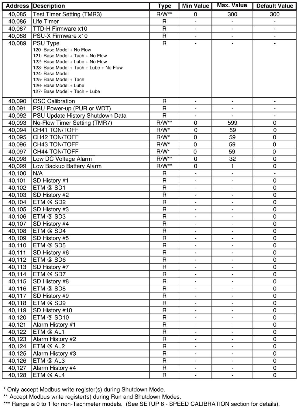
50 Modbus Register Address Listings

51
52
53 Specifications Power Requirements PSU-2: 10-32VDC, 10W (max); VDC CD Ignition, 100VDC (max) On-Board Backup Power: Lithium battery, 6 VDC, 1300 mah. Digital Inputs: 48 (a.k.a. Channels) Sensor Types: Discrete Input, N.O./N.C., non-incendive (with use of PSU-2). Magnetic Pickup Input One Magnetic Pickup Sensor Input: VAC, 2-10 khz. Outputs IGN: 400VDC (*) for 5 seconds RLY: 48VDC cont. duty 400VDC(*) cont. duty FV- : 400VDC (*) cont. duty ALR: 48VDC cont. duty AUX: 48VDC cont. duty (*) CSA approval for 250VDC maximum. Operator Interface Display Type: LCD, Static, 80 segment, custom text with LED Backlight Display Viewable Area: ~ 2.79 x 1 in. (71.04mm x 25.4mm) Display Contrast: Automatic Display Backlight: Yellow (Normal Operation), Red (Shutdown) (Backlight will only be available when unit is powered by DC or AC.) Voltage Level Monitor: Monitor and display voltage level of DC Supply, CD Ignition, and internal battery. Keypad: 6 switches: Ridge Embossed, Metal Dome, Tactile 14 Oz. Trip Force Enclosure Cutout: 5.50 x 5.50 inches (133 mm). Operating Temperature: -40 to +85 degrees C Viewable Temperature: -40 to +85 degrees C Storage Temperature: -40 to +85 degrees C Tachometer Accuracy: ±0.5% of the display reading or ±1 RPM, whichever is greater. Resetable Hourmeter Range: 0 to hrs. Non-Resetable Hourmeter Range: 0 to hrs. Hourmeter Accuracy: ±1 hour per year. Communication Port A single bi-color (GREEN/RED) LED is provided to give visual indication of active transmit and receive traffic. Only one connection will be active at any time. Interface: Factory configured for RS485; field-selectable for RS232 or RS485. Baud/Configuration: 9600, 19.2K, 38.4K(**);N,8,1;N,8,2 half-duplex communication Protocol: Modbus RTU slave Connection: There will be 2 screw terminals provided for RS485. There will be 2 screw terminals provided for RS232. There will be 1 screw terminal common for both ports labeled as GND. (**) 38.4K baud will not be available when IGN input is selected as the source for RPM calculations. When MPU is selected, this feature is available for selection Third Party Approvals TTD-H, PSU-2: CSA Class I, Division 2, Groups B, C, and D. TTD-H: IEC IP66 (NEMA 4 and 4X equivalent)
54 Intuitive Display Icons Display status and assist in setup and operation resulting in greater ease of operation and interface. The appropriate icon will turn on to indicate unit status or navigation through the setup features. RUN - Run mode RPM Screen Value HOURS Screen Value TYPE Channel Type Configuration LOW BATT Low Battery Warning (displayed only when condition exists) HISTORY Shutdown History TEST Test Mode LUBE Pre-lubrication Timer POSTLUBE Post-lubrication Timer SHUTDOWN Stop Mode ALARM Alarm(s) Warning (displayed only when condition exists) SETPOINT Edit Set-point Value SETUP Setup Menu(s)
55 TTD Replacement Parts and Assemblies

56
TTD Series Configurable Fault Annunciator. Installation and Operations Manual Section 50
 TTD Series Configurable Fault Annunciator Installation and Operations Manual 00-02-0697 2016-08-08 Section 50 In order to consistently bring you the highest quality, full-featured products, we reserve
WARNING. TTDJ Series Fully-Configurable Fault Annunciator Installation and Operations Manual
 TTDJ Series Fully-Configurable Fault Annunciator Installation and Operations Manual TTDJ-99062N Revised 04-04 Section 50 (00-02-0412) Please read the following information before installing. This installation
Series S1501 Selectronic Microcontroller/Annunciator. Installation and Operations Manual Section 50
 Series S1501 Selectronic Microcontroller/Annunciator Installation and Operations Manual 00-02-0819 2015-11-19 Section 50 Please read the following information before installing. BEFORE BEGINNING INSTALLATION
Series S1501 Selectronic Micro-Controller/Annunciator. Installation and Operations Manual Section 50
 Series S1501 Selectronic Micro-Controller/Annunciator Installation and Operations Manual 00-02-0271 06-16-09 Section 50 In order to consistently bring you the highest quality, full-featured products, we
5450 NW 33rd Ave, Suite 104 Fort Lauderdale, FL Fruitland Ave Los Angeles, CA UM Channel Monitor.
 5450 NW 33rd Ave, Suite 104 Fort Lauderdale, FL 33309 3211 Fruitland Ave Los Angeles, CA 90058 UM-600 6-Channel Monitor Version 2 Installation and Operation Manual Rev. G P/N145F-12990 PCO 00007462 (c)
6-Channel Monitor. Installation and Operation Manual
 3211 Fruitland Ave Los Angeles, CA 90058 Catalyst Monitor 6-Channel Monitor Version 2 Installation and Operation Manual Rev. H P/N145F-12964 PCO - 00009743 (c) Copyright 2015, Barksdale, Inc. All Rights
EMS467 Monitoring System. Installation and Operations Manual Section 40
 EMS467 Monitoring System Installation and Operations Manual 00-02-0672 01-26-10 Section 40 In order to consistently bring you the highest quality, full featured products, we reserve the right to change
CENTURION Configurable Controller. Installation and Operations Manual Section 50
 CENTURION Configurable Controller Installation and Operations Manual 00-02-0590 10-10-06 Section 50 In order to consistently bring you the highest quality, full featured products, we reserve the right
CENTURION - C4 Series Configurable Controller. Installation and Operations Manual Section 50
 CENTURION - C4 Series Configurable Controller Installation and Operations Manual 00-02-0696 2017-12-12 Section 50 FW Murphy has made efforts to ensure the reliability of the Centurion controller and to
CENTURION Configurable Controller. Installation and Operations Manual Section 50
 CENTURION Configurable Controller Installation and Operations Manual 00-02-0590 02-09-06 Section 50 In order to consistently bring you the highest quality, full featured products, we reserve the right
INSTALLATION INSTRUCTIONS
 www.altroniccontrols.com INSTALLATION INSTRUCTIONS EXACTA 21 MONITORING AND CONTROL SYSTEM CAUTION: The EXACTA 21 CONTROL SYSTEM is CSA CERTIFIED FOR use in Class I, GROUPS C & D, Division 2 hazardous
PowerCore Model TEC-10 Installation Manual
 PowerCore Model TEC-10 Installation Manual Products covered in this document comply with European Council electromagnetic compatibility directive 2014/30/EU and electrical safety directive 2014/35/EU.
MODEL DE-2000 FORM DE OI 9-01
 ALTRONIC ANNUNCIATOR SYSTEM OPERATING INSTRUCTIONS MODEL DE-2000 FORM DE OI 9-01 WARNING: DEVIATION FROM THESE OPERATING INSTRUCTIONS MAY LEAD TO IMPROPER ENGINE OPERATION WHICH COULD CAUSE PERSONAL INJURY
5450 NW 33rd Ave, Suite 104 Fort Lauderdale, FL Fruitland Ave Los Angeles, CA SST7000 SST7100. Speed Switch / Transmitter
 5450 NW 33rd Ave, Suite 104 Fort Lauderdale, FL 33309 3211 Fruitland Ave Los Angeles, CA 90058 SST7000 SST7100 Speed Switch / Transmitter Installation and Operation Manual Rev. C P/N145F-13112 PCO 00009270
ALTRONIC LOOP CONTROLLER INSTALLATION & OPERATING MANUAL MODEL DE-1500 FORM DE-1500 IOI 8-03
 ALTRONIC LOOP CONTROLLER INSTALLATION & OPERATING MANUAL MODEL DE-1500 FORM DE-1500 IOI 8-03 WARNING: DEVIATION FROM THESE OPERATING INSTRUCTIONS MAY LEAD TO IMPROPER ENGINE/MACHINE OPERATION WHICH COULD
LAUREL. Laureate Dual-Channel Pulse Input Totalizer With Two Independently Scalable Input Channels & Presets ELECTRONICS, INC. Features.
 Description LAUREL ELECTRONICS, INC. Laureate Dual-Channel Pulse Input Totalizer With Two Independently Scalable Input Channels & Presets Features Frequencies up to 1 MHz Totals stored in non-volatile
*Approved by CSA for non-hazardous locations (Group Safety Publication IEC Third Edition).
.") PowerCore Model MPC-20 Installation Manual *Approved by CSA for non-hazardous locations (Group Safety Publication IEC 61010-1 Third Edition). Products covered in this document comply with European Council
PowerCore Model MPC-20 Installation Manual *Approved by CSA for non-hazardous locations (Group Safety Publication IEC 61010-1 Third Edition). Products covered in this document comply with European Council
ETM MD100 Drive System 1/2HP (370W) User Manual. Table of Contents. Drive Features
 User Manual. Table of Contents. Drive Features") Table of Contents Drive Features... 1 Drive Specifications... 2 Certifications... 3 Installation - Drive Dimensions... 3 Motor Dimensions (mm)... 4 Drive Mounting... 4 Wiring... 5 I/O Terminals... 9 Menu...
Table of Contents Drive Features... 1 Drive Specifications... 2 Certifications... 3 Installation - Drive Dimensions... 3 Motor Dimensions (mm)... 4 Drive Mounting... 4 Wiring... 5 I/O Terminals... 9 Menu...
1.6. Counters, Panel Meters, Tachometers and Timers. Contents Description Fusion Integrated Machine Control Standards and Certifications...
 .6 Contents Standards and Certifications............... Product Selection....................... Technical Data and Specifications........... Dimensions............................ Learn Online Page V3-T-04
Energy Management System. Operation and Installation Manual
 Energy Management System Operation and Installation Manual AA Portable Power Corp 825 S 19 TH Street, Richmond, CA 94804 www.batteryspace.com Table of Contents 1 Introduction 3 2. Packing List 5 3. Specifications
3690 N.W. 53rd Street Fort Lauderdale, FL SC-2124 SC-2124M. 24 Channel Universal Scanner. Installation and Operation Manual P/N 145F-11902
 3690 N.W. 53rd Street Fort Lauderdale, FL 33309 SC-2124 SC-2124M 24 Channel Universal Scanner Installation and Operation Manual P/N 145F-11902 Rev. 3.30 (c) Copyright 2000, Dynalco Controls All Rights
Sidewinder Pumps Inc. AC C1D2 Timer/Controller
 Sidewinder Pumps Inc. AC C1D2 Timer/Controller Page 1 of 14 Rev 4/26/17 Table of Contents 1. Warnings --------------------------------------------------------------------------------------------------
2 Table of Contents 1. TABLE OF CONTENTS. 1. Table of Contents Introduction Wiring Diagram Terminals Review...
 TPR-6 Temperature Protection Relay Instruction Manual Ver. June 1 st 2010 2 Table of Contents 1. TABLE OF CONTENTS 1. Table of Contents... 2 2. Introduction... 3 3. Wiring Diagram... 5 4. Terminals Review...
MYRIAD QLC 4-CHANNEL MONITOR/CONTROLLER INSTRUCTION MANUAL
 MYRIAD QLC 4-CHANNEL MONITOR/CONTROLLER INSTRUCTION MANUAL VISIT OUR WEBSITE SIGMACONTROLS.COM MYR QLC MANUAL 013114 2 TABLE OF CONTENTS INTRODUCTION 3 Ordering Information Specifications Features WIRING
Quick Start Installation Guide
 istar Pro Quick Start Installation Guide Version B0 Part Number UM-069 January 2005 OVERVIEW This guide defines all of the commonly used connection methods to the istar Pro. It outlines how to wire readers
RTU560 Connections and Settings DIN Rail RTU 560CIG10
 Connections and Settings DIN Rail RTU 560CIG10 Application, characteristics and technical data have to be taken from the hardware data sheet: 560CIG10 1KGT 150 719 Operation The 560CIG10 is a DIN rail
Manual# Installation Manual SDU 410. Safety Shutdown Unit
 Manual# 1100641 Installation Manual SDU 410 Safety Shutdown Unit Installation Manual for SDU 410 ~~~ Safety Shutdown Unit Revision 1.0 Revised August 31, 2017 Revision history: Rev. Date Description 1.0
QUICK START. Installation & Programming Guide
 QUICK START Installation & Programming Guide PRECAUTIONS READ AND FOLLOW ALL SAFETY INSTRUCTIONS. CAUTION - RISK OF ELECTRICAL SHOCK. To prevent electrical shock, turn off power at the circuit breaker
S7999D SOLA Operator Interface Display
 S7999D Operator Interface Display INSTALLATION INSTRUCTIONS APPLICATION The S7999D is microprocessor-based color touch-screen Operator Interface (OI) display that provides an operator interface for monitoring
7511 / / / 711 / / 731 / Preset 27
 22 Timers Timers Electronic 23 7511 / 3410 23 6320 / 720-6300 24 ElectRo-MeCH 25 710 / 711 / 720 25 722 / 731 / 732 26 Preset 27 7932 27 Electronic 23 7511 Series 8 digit self powered LCD electronic timer
Installation and Operating Instructions
 Installation and Operating Instructions Modbus Terminal Board Form MTB IOI 4-12 1.0 DESCRIPTION 1.1 The Modbus Terminal Board is an RS-485, MODBUS RTU slave board capable of reading 33 channels. The first
DE SERIES. Enhanced DE-2500 System Now Available. Programmable Safety Shutdown, Monitoring and Control Products with Analog Input Capabilities
 Enhanced DE-2500 System Now Available DE SERIES Programmable Safety Shutdown, Monitoring and Control Products with Analog Input Capabilities A state-of-the-art family of products specifically designed
EP/2 Installation Instructions
 1 2 3 4 7 ENTER 0 5 6 8 9 CLEAR + - LOGIC ONE EP/2 EP/2 Installation Instructions DOC. #569011000 A 7/30/04 PRINTED IN U.S.A. Regulatory Compliance Safety This device has been tested and found to be in
Y800 Plus Frequency, Rate & Period Meter With dual, independently field-scalable channels
 Y800 Plus Frequency, Rate & Period Meter With dual, independently field-scalable channels Description Features Frequencies from 0.005 Hz to 1 MHz 6-digit resolution at update rates up to 25/s Selectable
Installation and Programming Manual. Niobrara Research & Development Corporation P.O. Box 3418 Joplin, MO USA
 DUCM DF1 Manual DUCM DF1 Installation and Programming Manual This manual describes the DUCM application for interfacing DF1 slaves to a Modbus or RNIM serial network. Effective: February 16, 2017 Niobrara
Genset Controller Unit Model EMS - GC10. Installation Manual Section
 Genset Controller Unit Model EMS - GC10 Installation Manual 00-02-0794 Section 75 2013-01-28 In order to consistently bring you the highest quality, full featured products, we reserve the right to change
Datapanel. Datapanel 40/45, 60/65 & 85. Operator Interface Products. User's Manual
 Datapanel Operator Interface Products Datapanel 40/45, 60/65 & 85 User's Manual GFK-1806A Nov. 2001 Warnings, Cautions, and Notes as Used in this Publication Warning Warning notices are used in this publication
Digital Keypad Introduction
 K2 Digital Keypad Introduction The K02 uses the latest microprocessor technology to operate door strikes and security systems that require a momentary (timed) or latching dry contact closure. All programming
5504 Thermocouple Analog Input Module
 550 Thermocouple Analog Input Installation, Operation and Maintenance Setup Manual 5/9/0 Safety Information The information provided in this documentation contains general descriptions and/or technical
Autoranging True RMS Multimeter User Manual
 Autoranging True RMS Multimeter User Manual Please read this manual before switching the unit on. Important safety information inside. Contents Page 1. Safety Information... 4 2. Safety Symbols... 5 3.
TraceTek Leak Detection Master Module Installation Instructions TOOLS REQUIRED STORAGE
 TTDM-128 TraceTek Leak Detection Master Module Installation Instructions TRACETEK APPROVALS AND CERTIFICATIONS TYPE NM General Signaling Equipment 76LJ GENERAL INFORMATION Please read these instructions
EXPRESS SETUP. PanelMate 1700 Series PanelMate Power Pro. Cutler-Hammer
 EXPRESS SETUP PanelMate 1700 Series PanelMate Power Pro Cutler-Hammer Installation Unpacking Carefully remove all equipment from the packing cartons and inspect all parts for damage in shipment. Check
OPERATING INSTRUCTION
 OPERATING INSTRUCTION AUTORANGING MULTIMETER MAX Ω F C 10A MAX every 15 min. COM V SAFETY INFORMATION The following safety information must be observed to insure maximum personal safety during the operation
Operating Instructions
 Operating Instructions DE-3000 Series Configurable Safety Shutdown and Control System with Graphing Capabilities Form SOME FEATURES IN THIS MANUAL ARE ONLY APPLICABLE TO DE-3000 FIRMWARE DATED 2014 OR
INTEGRATED SYSTEMS AND CONTROL, INC. User s Hardware Manual. PCMNET V 7. xx
 INTEGRATED SYSTEMS AND CONTROL, INC. User s Hardware Manual PCMNET V 7. xx INTEGRATED SYSTEMS AND CONTROLS, INC. PCMNET Users Manual Revised 2/4/2005 2003-2005 Integrated Systems and Control. Inc. PO Box
Service Bulletin SB685. Date: 8/18/2017 TriPac EVOLUTION Communications Update Bulletin Location: TSA Info Central\Service Bulletins
 Service Bulletin SB685 Date: 8/18/2017 Subject: TriPac EVOLUTION Communications Update Bulletin Location: TSA Info Central\Service Bulletins Units: All TriPac EVOLUTION Summary: This bulletin updates and
OPERATIONS MANUAL. n.form I/O Expander (RACK MOUNT) Document Number: Rev B
 Document Number: Rev B") OPERATIONS MANUAL n.form I/O Expander (RACK MOUNT) Document Number: 200-0009 Rev B table of contents INTRODUCTION FEATURES & CAPABILITIES 1 WIRING General I/O Configuring The System Using The System 4
OPERATIONS MANUAL n.form I/O Expander (RACK MOUNT) Document Number: 200-0009 Rev B table of contents INTRODUCTION FEATURES & CAPABILITIES 1 WIRING General I/O Configuring The System Using The System 4
Panel Indicators. NEW 4~20mA Panel Display. Process Indicators INTECH INSTRUMENTS.
 The LPI-LCD-6-4~20mA panel display is ideal for displaying a variety of process variables, and is easy to scale to your required engineering units. LPI-LCD-6 4~20mA Panel Display. Loop powered. Loop powered
GV3000/SE Operator Interface Module (OIM) User Guide Version 2.0 M/N 2RK3000
 User Guide Version 2.0 M/N 2RK3000") GV3000/SE Operator Interface Module (OIM) User Guide Version 2.0 M/N 2RK3000 Instruction Manual D2-3342-2 The information in this manual is subject to change without notice. Throughout this manual, the
GV3000/SE Operator Interface Module (OIM) User Guide Version 2.0 M/N 2RK3000 Instruction Manual D2-3342-2 The information in this manual is subject to change without notice. Throughout this manual, the
Quick Installation Guide
 Manual# 1100274 Quick Installation Guide SDU 410 Safety Unit Quick Installation Guide for SDU 410 Safety Unit ~~~ Revision 1.1 Revised November 10, 2016 Revision history: Rev. Date Description 1.0 04.2012
Installation & Operation
 LED Readout Installation & Operation WARRANTY Accurate Technology, Inc. warrants the ProScale Systems against defective parts and workmanship for 1 year commencing from the date of original purchase. Upon
MCCB-250 MOLDED-CASE CIRCUIT BREAKER TESTER
 MCCB-250 MOLDED-CASE CIRCUIT BREAKER TESTER USER S MANUAL Vanguard Instruments Company, Inc. 1520 S. Hellman Ave. Ontario, California 91761, USA TEL: (909) 923-9390 FAX: (909) 923-9391 January 2015 Revision
AirTest Model CN9000 Series Sensor Controller
 AirTest Model CN9000 Series Sensor Controller AirTest Model CN9000 Series Sensor Controller THEORY OF OPERATION A basic CN9000 configuration consists of Input/Process/Display combination modules, a 3 relay
HelmView 450 Model HV450. Installation Manual Section 78
 HelmView 450 Model HV450 Installation Manual 00-02-0727 2015-04-16 Section 78 In order to consistently bring you the highest quality, full-featured products, we reserve the right to change our specifications
HPS-M -2 DIFFERENTIAL PRESSURE TRANSMITTER. Mounting and operating instructions
 DIFFERENTIAL PRESSURE Mounting and operating instructions Table of contents SAFETY AND PRECAUTIONS 3 PRODUCT DESCRIPTION 4 ARTICLE CODES 4 INTENDED AREA OF USE 4 TECHNICAL DATA 4 STANDARDS 5 OPERATIONAL
PF2100 MODBUS LOGGER CARD SYSTEM SPECIFICATION. v1.0 DRAFT Revised Dec 4, 2014 Last Revised by Alex Messner
 PF2100 MODBUS LOGGER CARD SYSTEM SPECIFICATION Revised Last Revised by Alex Messner This page was intentionally left blank. Table of Contents 1 Overview... 2 2 User Interface... 3 2.1 LEDs... 3 2.2 Buttons...
TABLE OF CONTENTS INTRODUCTION. 3. Analog Input Analog Output Digital Input Digital Output OPERATIONAL DESCRIPITON.. 7 PROGRAMMING AND INITIAL SETUP.
 DIVERSIFIED HEAT TRANSFER SERIES 700 STEAM GENERATOR CONTROLLER INSTRUCTION MANUAL VISIT OUR WEBSITE AT SIGMACONTROLS.COM SERIES 700 DHT STEAM GENERATOR MANUAL 042514 2 TABLE OF CONTENTS INTRODUCTION.
INSTALLATION DKM-409 NETWORK ANALYSER WITH HARMONIC MEASUREMENT AND SCOPEMETER. Before installation:
 DKM-409 NETWORK ANALYSER WITH HARMONIC MEASUREMENT AND SCOPEMETER The DKM-409 is a precision instrument designed for displaying various AC parameters in 3-phase distribution panels. Thanks to its isolated
Buffered Power Supply PS-30DR v1.0
 Roger Access Control System Buffered Power Supply PS-30DR v1.0 Document version: Rev. C Firmware: 1.0.4 1. PRODUCT DESCRIPTION The PS-30DR is dedicated for electronic equipment which require 12VDC buffered
Installation Manual. CSC400 Combustion Safety Controller (Rev 1D)
") Installation Manual for the CSC400 Combustion Safety Controller (Rev 1D) WARNING This manual must be read in its entirety before installation of this controller. Installation must be performed by a qualified
Installation Manual for the CSC400 Combustion Safety Controller (Rev 1D) WARNING This manual must be read in its entirety before installation of this controller. Installation must be performed by a qualified
PowerView Model PV485. Installation Manual Section 78
 PowerView Model PV485 Installation Manual 00-02-1018 2017-05-23 Section 78 In order to consistently bring you the highest quality, full-featured products, we reserve the right to change our specifications
MODBUS RTU I/O Expansion Modules - Models C267, C277, and C287. Installation and Operations Manual Section 50
 MODBUS RTU I/O Expansion Modules - Models C267, C277, and C287 Installation and Operations Manual 00-02-0651 09-01-09 Section 50 In order to consistently bring you the highest quality, full featured products,
Scanner 2000 microefm QuickStart. Installing the Scanner Remote Mount. Direct Mount NUFLO. Part No , Rev. A
 NUFLO Part No. 30165024, Rev. A Scanner 2000 microefm QuickStart Installing the Scanner 2000 H L H L Flow Direct Mount To install the Scanner 2000 microefm using a direct mount to an orifice or cone meter
This document set is applicable to the following part number configurations:
 This document set is applicable to the following part number configurations: Part Number Kit Configuration Instrument Sensor TM202 TM202 - TM202B TM202 1 X A200-HMB TM202S TM202 1 X A200-HMS TM202R TM202
TABLE OF CONTENTS TABLE OF CONTENTS... 1 IMPORTANT SAFETY NOTICE...
 TABLE OF CONTENTS TABLE OF CONTENTS... 1 IMPORTANT SAFETY NOTICE... 2 1.0 General Information... 3 1.1 System Components... 3 1.2 Specifications... 3 1.2.1 Torque Ranges... 3 1.2.2 Electrical Specifications...
6222 Two Door Module Technical Operations Manual
 6222 Two Door Module Technical Operations Manual TABLE OF CONTENTS Specifications...3 Overview...4 Operations...5 Custom Access Mode...5 Standard Access Mode...5 Offline Access Mode...5 Offline Memory...5
ControlKeeper 4. General Information. Connecting Relay Loads. Installation Sheet. Getting Started. Power Supply Wiring. Mounting the Cabinet
 General Information ControlKeeper 4 Installation Sheet Model# CK4-120NO- Model# CK4-277NO The ControlKeeper-4 model is shipped in one package and is configured with either a 120V or a 277V transformer.
INSTRUCTION MANUAL STATION CONTROLLER SC1000 MOTOR PROTECTION ELECTRONICS, INC.
 INSTRUCTION MANUAL STATION CONTROLLER SC1000 MOTOR PROTECTION ELECTRONICS, INC. 2464 Vulcan Road, Apopka, Florida 32703 Phone: (407) 299-3825 Fax: (407) 294-9435 Revision Date: 9-11-08 Applications: Simplex,
S-14 S-14. Compact Digital Multimeter. Compact Digital Multimeter
 S-14 Compact Digital Multimeter S-14 Compact Digital Multimeter SAFETY INFORMATION The following safety information must be observed to insure maximum personal safety during the operation at this meter
U-FLASH Setup Guide U-FLASH.
 U-FLASH Setup Guide Thank you for purchasing the U-FLASH. This guide will assist you in the setup of the system. You can call for FREE technical support to get help anytime at 757-258-0910. Please note,
Pro-Star AVW200 Installation and Operation Manual Protel, Inc. ALL RIGHTS RESERVED AVW200HM01.1
 Pro-Star AVW200 Installation and Operation Manual 2005 Protel, Inc. ALL RIGHTS RESERVED AVW200 Installation and Operation Manual Revision History Revision Date Description of Changes AVW200HM01.0 12/05
Quick Start Guide MC-III TM Flow Analyzer
 Quick Start Guide MC-III TM Flow Analyzer A Quick Reference on Mounting, Wiring, & Configuring the MC-III EXP or WP Flow Analyzer For complete instructions, see MC-III EXP User Manual, Part No. 9A-50165003
CRAGG RAILCHARGER Instruction Manual for 10DTC-12V 20DTC-12V 30DTC-24V 40DTC-12V 60DTC-12V
 CRAGG RAILCHARGER for 10DTC-12V 20DTC-12V 30DTC-24V 40DTC-12V 60DTC-12V Contents 1 Warnings, Cautions, and Notes... 1 2 Description... 2 3 Features... 2 3.1 STANDARD FEATURES... 2 3.2 CHARGER REGULATION...
Version Accurate Technology, Inc.
 Single Axis Position Control Unit (PCU) User s Manual Version 2.040 270 Rutledge Rd. Suite E Fletcher, North Carolina 28732 USA 828-654-7920 www.proscale.com The contents of this document are protected
M2 Wireless Gateway and Remotes. Installation and Operations Manual Section 50
 M2 Wireless Gateway and Remotes Installation and Operations Manual 00-02-0674 06-08-11 Section 50 In order to consistently bring you the highest quality, full featured products, we reserve the right to
GV3000/SE AC Drive ControlNet Network Communication Option Board M/N 2CN3000
 GV3000/SE AC Drive ControlNet Network Communication Option Board M/N 2CN3000 Instruction Manual D2-3390-2 The information in this manual is subject to change without notice. Throughout this manual, the
NCH-1000 (Multiple Breaker Types) Installation Instructions
 Installation Instructions") 20M1 12345678 NCH-1000 (Multiple Breaker Types) Installation Instructions DOC. #560502100 C 7/30/04 PRINTED IN U.S.A. Regulatory Compliance Safety This device has been tested and found to be in compliance
20M1 12345678 NCH-1000 (Multiple Breaker Types) Installation Instructions DOC. #560502100 C 7/30/04 PRINTED IN U.S.A. Regulatory Compliance Safety This device has been tested and found to be in compliance
Centurion C5 M-VIEW Monochrome LCD (MV-5-C) Operations Manual Section 50
 Operations Manual Section 50") Centurion C5 M-VIEW Monochrome LCD (MV-5-C) Operations Manual 00-02-1031 2019-02-14 Section 50 BEFORE BEGINNING INSTALLATION OF THIS FW MURPHY PRODUCT: Please read the following information before operating
Centurion C5 M-VIEW Monochrome LCD (MV-5-C) Operations Manual 00-02-1031 2019-02-14 Section 50 BEFORE BEGINNING INSTALLATION OF THIS FW MURPHY PRODUCT: Please read the following information before operating
PanelView Plus/VersaView CE Terminals and Display Modules
 Installation Instructions PanelView Plus/VersaView CE Terminals and Display Modules (Catalog Numbers 2711P-xxxxxx, 6182H-xxxxxx) English Inside: Overview...2 For More Information...2 Modular Components...3
Section 1 General Description. Section 3 How to Program Keypad. Section 2 Installation. CM-120TX Wireless Digital Keypads Installation Instructions
 CM-120TX Wireless Digital Keypads Installation Instructions Package Contents - (1) Keypad and faceplate assembly - (1) Foam gasket (CM-120W only) - (2) #6-32 x 1 S/S Phillips screws - (2) #6-32 x 1 Tamperproof
MYRIAD LC1 LEVEL CONTROLLER INSTRUCTION MANUAL
 MYRIAD LC1 LEVEL CONTROLLER INSTRUCTION MANUAL VISIT OUR WEBSITE SIGMACONTROLS.COM MYR LC1 MANUAL 062114 TABLE OF CONTENTS INTRODUCTION 3 Ordering Information Specifications Features Dimensions WIRING
ProScale LCD Readout Quick Start Guide
 ProScale LCD Readout Quick Start Guide This Guide includes basic operation instructions for 950, General Purpose, Basic & In-Panel LCD Readouts For the Complete OPERATION Manual go to www.proscale.com/manuals.htm
LAUREL. Laureate Pulse or Analog Input Batch Controller Automatic batch control for repetitive liquid fill operations ELECTRONICS, INC.
 Description LAUREL ELECTRONICS, INC. Laureate Pulse or Analog Input Batch Controller Automatic batch control for repetitive liquid fill operations Features Available for turbine flow meter pulse signals
SS2200 Remote Controller
 SS2200 Remote Controller General Purpose, DC Voltage General The SS2200 Remote Controller is a microprocessor-based programmable controller specifically designed to control single line and dual line centralized
Quick Start Installation Guide
 apc/l Quick Start Installation Guide Version A2 Document Part Number UM-201 May 2010 OVERVIEW The apc/l is an intelligent access control and alarm monitoring control panel which serves as a basic building
LAUREL ELECTRONICS, INC.
 Description LAUREL ELECTRONICS, INC. Laureate Pulse or Analog Input Batch Controller Automatic batch control for repetitive liquid fill operations Features Available for turbine flow meter pulse signals
Operating Manual IN-LINE ENGINE CONTROL SYSTEM. Form GPN1000 OM 11-12
 Operating Manual IN-LINE ENGINE CONTROL SYSTEM Form GPN1000 OM 11-12 1.0 OVERVIEW 1.1 This manual applies to GPN1000 and GPN1000-12 panels used with Series 25-A, 50-A, 65-A, and 65-B (formerly Series A-A,
HAND-HELD THERMOCOUPLE THERMOMETER SERVICE MANUAL. CATALOG NUMBERS , and , and PROPRIETARY
 HAND-HELD THERMOCOUPLE THERMOMETER SERVICE MANUAL CATALOG NUMBERS 600-1000, 600-1010 and 600-1020 91100-00, 91100-10 and 91100-20 PROPRIETARY Information contained in this manual is proprietary to COLE-PARMER
CROSSFIRE Ultra-Low Power Chemical Injection Pump
 CROSSFIRE Ultra-Low Power Chemical Injection Pump Introduction The LCO Technologies CROSSFIRE Chemical Injection pump is an ultra-low power device that is designed to reduce chemical costs, maintenance
Model HM-535 Power Supply Installation and Service Instructions
 Model HM-535 Power Supply Installation and Service Instructions 430-535 0104 2004 Heritage MedCall, Inc SENTRY INSTALLATION & SERVICE INSTRUCTIONS POWER SUPPLY UNIT Model HM-535 IMPORTANT SAFETY INSTRUCTIONS
Contents 1 Warnings, Cautions, and Notes Description Features... 1
 EnCell Contents 1 Warnings, Cautions, and Notes... 1 2 Description... 1 3 Features... 1 3.1 STANDARD FEATURES... 1 3.2 FRONT PANEL FEATURES... 2 3.2.1 Display... 2 3.2.2 OK LED... 2 3.2.3 FAULT LED...
Manual Control Unit GFC 32
 Manual Control Unit 1400004_EN/05.2017 Index 1. Main features 3 2. Technical features 3 3. Installation guidelines 4 4. Preliminary checks 5 5. Electrical connections 5 6. Settings 6 7. Remote control
InteliLite MRS17 Click Here to Learn More
 InteliLite MRS17 Click Here to Learn More Comprehensive Genset Controller Brief Description The InteliLite is a cost effective controller for generator sets in stand-by and prime power applications. The
Manual# Installation Manual. 400E Series. DCU 410E Engine Control Unit RP 410E Remote Panel
 Manual# 1100346 Installation Manual 400E Series DCU 410E Engine Control Unit RP 410E Remote Panel RP 410E DCU 410E Installation Manual for Marine Pro 400E Series ~~~ DCU 410E Engine Control Unit RP 410E
M2110F SMART FLOW GAUGE OPERATING INSTRUCTIONS
 9R142 Dated 2/1/11 M2110F SMART FLOW GAUGE OPERATING INSTRUCTIONS Meriam s M2110F Smart Flow Gauge is a microprocessor-based pressure sensing device with algorithms to calculate flow. The gauge provides
EnCell Battery Cell Monitor
 EnCell Battery Cell Monitor Instruction Manual Model RCM15S12 NERC Compliant YO R U H T PA TO Z O R E W O D N M I T E enchargepowersystems.com sales@enchargepowersystems.com (888) 407.5040 Contents 1 Warnings,
Girard Awnings R ACMC Motor Controller (Last revised on May 10, 2008) A Visionary Awning Control by
 A Visionary Awning Control by") Girard Awnings R ACMC Motor Controller (Last revised on May 10, 2008) R A Visionary Awning Control by Girard AC Motor Controller Installation Guide ACMC Revision 2.08 May 10, July 2008 ACMC Installation
Girard Awnings R ACMC Motor Controller (Last revised on May 10, 2008) R A Visionary Awning Control by Girard AC Motor Controller Installation Guide ACMC Revision 2.08 May 10, July 2008 ACMC Installation
Model OI x82 ProSafe
 Model OI-7480 4x82 ProSafe Operation Manual Revision 2.2.1w Product Overview The Otis Instruments, Inc. GenII ProSafe 4x82 Model OI-7480 is a eight (or twelve) channel gas monitor that functions as a transmission
170 ADM to 60 VDC Module Base / 170 ADO Pt. Relay Out Module Base. Version 1.0
 170 ADM 850 10 10 to 60 VDC Module Base / 170 ADO 830 30 6 Pt. Relay Out Module Base Version 1.0 31005197 00 Safety Information NOTICE Read these instructions carefully, and look at the equipment to become
INSTALLATION INSTRUCTIONS 921P EntryCheck TM
 80 Avenida Acaso, Camarillo, Ca. 90 (805) 494-06 www.sdcsecurity.com E-mail: service@sdcsecurity.com INSTALLATION INSTRUCTIONS 9P EntryCheck TM The EntryCheck 9P Indoor/Outdoor Keypad is a surface mount