Bale Wrapper Controller (RA)
|
|
|
- Arthur Palmer
- 6 years ago
- Views:
Transcription

1 Bale Wrapper Controller (RA) For Models 1300, 1510, 1514 Operating Instructions RDS Part No.: Document Issue: Software Issue: S/DC/ A: 24/3/03 EX
2 TANCO AUTOWRAP Electromagnetic Compatibility (EMC) This product complies with Council Directive 89/336/EEC when installed and used in accordance with the relevant instructions. Our policy is one of continuous improvement and the information in this document is subject to change without notice. Check that the software reference matches that displayed by the instrument. Copyright RDS Technology LTD 2003 \UK391-A.DOC Service and Technical Support PLEASE CONTACT YOUR NEAREST TANCO DEALER OR TANCO Tanco Autowrap Ltd Bagenalstown Co. Carlow Ireland Tel: +353 (0) Fax: +353 (0) web: Contents 1. INTRODUCTION IMPORTANT SAFETY INFORMATION! Main operating Functions and Display OPERATION Operation in Automatic mode Manually interrupting an automatic wrapping cycle Manual options in Automatic mode Operation in Manual mode The Display Menu Selecting a Store Total Resetting a Store Total to Zero Setting the Number of Wraps OPERATOR SETUP MENU 7 2

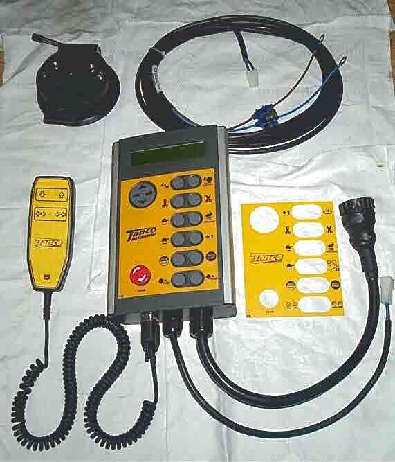
3 TANCO AUTOWRAP 1. Introduction The Tanco Autowrap Bale Wrap Controller enables the operator to monitor and control the operation of the bale wrapper at any stage of the wrapping cycle. The controller is designed for models : 1300EH, 1510EH, 1510T, 1514S, and 1514T rotating-arm type wrappers. There are 2 operating modes Automatic and Manual. The automatic mode permits one-touch wrapping to ease the workload on the operator. The controller is fully programmable to optimise wrapping performance. Bale counts are automatically logged in any one of 10 selectable memory stores, in addition to a grand total memory store. 1.1 IMPORTANT SAFETY INFORMATION! Please read and understand the instructions for using this controller before operating the machine. This controller is fitted with a pushbutton type On/Off Emergency Stop switch. Always ensure the controller is switched OFF via this switch before attempting any adjustment or maintenance to the machine. Please follow ALL other safety instructions given in the manufacturers Operator Handbook for this machine. 1.2 Main operating Functions and Display The principal instrument features and operating functions are shown in figure 1 below. Figure 1 4-way Menu switch to Set No. of wraps Change/reset bale sub-total Access Operator Setup menu Access Technician Setup menu Add 1 wrap to current (or next) bale A 2-line, 32 character dot matrix, back-lit display shows in the normal operating mode: Current No. of wraps Target No. of wraps Wrapping speed (rpm) Bale total (10 separate stores) Grand Total No. of bales Mode ( M manual, A Auto) Pause wrapping Cut and grip film Slow wrap Reverse wrap arm Select Operating Mode Bale unload Power On/Off /Emergency Stop Release film grip Fast wrap / Resume wrap after manually pausing Index Bale (outside auto-wrap cycle) Pause bale rotation (during autowrap cycle)- Start Automatic cycle (Press STOP switch to stop cycle e.g. in an emergency, otherwise press to pause the cycle) Bale load 3
, bring the machine up to the bale. 2. Press the switch* to move the rollers to the closed position.")

4 TANCO AUTOWRAP 2 Operation 2.1 Operation in Automatic mode The controller is generally used in automatic mode for one touch wrapping. 1. A on the display indicates that the controller is set in Automatic mode. If not, press to select. 2. With the rollers in the open position (step 4), bring the machine up to the bale. 2. Press the switch* to move the rollers to the closed position. 3. Press the switch to commence the automatic wrapping cycle. The cycle is completed when the target number of wraps has been reached. 4. Press the switch* to move the rollers to the open position to unload the bale. * The controller must be configured in the Operator Setup menu (section 3) so that this is a one touch function in automatic mode. Otherwise you must hold the switch for the required duration (as remains the case in manual mode). 2.2 Manually interrupting an automatic wrapping cycle Press the switch to bring the wrapper to a controlled stop. Pressing the switch will continue the autowrap cycle from where it stopped. For safety reasons, if it is necessary to work on the machine (e.g. in the event of a film break or the film running out), then it is strongly recommended that you then switch the controller off via the red stop button and disengage the machine power source. Pressing the switch after switching the controller back on will resume the auto-wrap cycle from where it stopped. Unless it is an emergency situation, do not bring the machine to a stop by pressing the red stop button as this will impose unnecessary strain on the machine. 2.3 Manual options in Automatic mode With the controller in automatic mode, the following manual functions are possible. SLOW WRAP (not during the wrapping sequence). Press to resume the normal fast wrap. REVERSE WRAP ARM (only enabled outside of the wrapping sequence). Press this button to nudge the wrap arm backwards to the desired position. PAUSE BALE ROTATION (function active during auto-wrap cycle). Hold this button to add more film to a particular part of the bale. Release the button when sufficient additional film has been applied. BALE INDEXING (function active outside auto-wrap cycle). Press and hold this button to index the bale. Release the button when the bale is at the desired position. NOTE: The controller can be configured from the Operator Setup menu (section 3) so that this is a one-touch function and the bale will then index for the preset period (e.g. to allow a ¼ turn). ADD 1 WRAP Each time you press this button an additional wrap will be put on the current bale if the wrapping sequence is in progress, or onto the next bale if the automatic cycle has not yet been started. You can add as many wraps as required. 2.4 Operation in Manual mode M on the display indicates that the controller is set in manual mode. If not, press to select. In manual mode you have total control of every stage of the wrapping cycle. The software logic determines which manual functions can be activated at any point in the wrapping cycle. Should the operator incorrectly select a function at a certain stage during the wrapping cycle, then that operation will not be performed. 4
5 TANCO AUTOWRAP 2.5 The Display Menu The Display menu is divided into 3 sections. At the top level are the settings used during the daily work with the machine i.e. Store totals and No. of Wraps. The Operator Setup section enables the operator to perform adjustments to the machine operation e.g. time duration and time delay settings during the automatic cycle. The Technician Setup menu is not normally accessible to the operator without a PIN access code. Technician Setup is not covered by this manual. Use the 4-way switch to navigate the menu. Each menu screen indicates which keys to press to make the settings. The instrument will default back to the main operating display after 30 seconds if no other key is pressed Here is a summary of the display menu; Default display Function 1300EH 1510EH 1514S 1510T 1514T Range Res. Contrast Sequence T 1514T Film Break OFF OFF OFF OFF OFF ON/OFF Double Drive OFF OFF ON/OFF Stop Bale Rotation* No No No Yes/No Delay before slow at end Delay to stop after last pulse Rotation after Wrapping Manual Rollers In Hold On Duration Manual Rollers Out Hold On Duration Manual Index Bale Hold On Duration Language English English English English English E/F/D/NL/ DK NOTE: There are additional sequences selectable in the Operator Setup menu but not shown in the table. These sequences are for wrapper models to which this manual does not apply. Please refer to section 3 for further explanation of the Operator Setup functions given in the table above. 5
6 TANCO AUTOWRAP 2.6 Selecting a Store Total There are 10 individual memory registers labelled Store A to Store J for bale totals. Each time a bale cycle is completed, the currently selected store total and the grand total increments by 1. The currently selected store is displayed on one of the two screens selectable in the normal operating mode. The default setting is Store A. To select a particular store, navigate the display menu using the 4-way switch. Press the up/down arrow keys to select the store, then press the ENTER key to confirm the selection. 2.7 Resetting a Store Total to Zero Stores A to J can be individually reset to zero at any time. The Grand Total store cannot be reset. First select the store to be zeroed, then navigate the display menu as shown below. Press the ENTER key to reset. 2.8 Setting the Number of Wraps The default number of wraps is 16. You can set the target number from 0 to 99 by navigating the display menu as shown below. 6

7 TANCO AUTOWRAP 3 Operator Setup Menu The default settings for the machine are developed by Tanco for optimal operation of the machine. However, the operator can change certain parameters in the Operator Setup menu to take account of operational conditions. Parameter Default Application Description Film Break OFF N/A N/A Double Drive OFF 1514S, 1514T only Stop Bale Rotation Delay to Slow 1.0s No 1510S, 1514S, 1514T only 0.4s Delay to Stop 1.0s 0.9s 1300EH, 1510S, T, 1514T 1300EH, 1510S, T, 1514T Set ON to enable both pairs of rollers to be driven. Set Yes to delay bale rotation for a preset time period after the wrap cycle begins. This enables additional wraps of film to be applied for extra strength e.g. when wrapping two bales together. Determines the point of speed reduction at the end of the wrapping cycle Set to adjust the Stop position of the wrap arm Rotation After 0.0s All Set time period to rotate the bale to an optimal orientation for unloading IN Hold Time 0.0s All Sets the latch-on time period for closing the bale rollers. Effectively allows one touch operation instead of having to hold the switch in Automatic mode. Does not apply when in Manual mode OUT Hold Time 0.0s All Sets the latch-on time period for opening the bale rollers. Effectively allows one touch operation instead of having to hold the switch in Automatic mode. Does not apply when in Manual mode Bale Hold ON 0.0s All Sets the latch on time period for indexing a bale. Effectively allows one touch operation instead of having to hold the switch in Automatic mode (e.g. to index a ¼ turn). Language English All Sets the language for the display prompts. 7
8
9

10 7.2. EH Controller ITEM PART NO. QUANTITY DESCRIPTION RA Control Unit RA Faceplate RDS pin connector Female + 2 spade pins pin socket Controller mounting bracket EH Controller suction cup Extension Cable (4m) Battery Cable (3m) pin connector male + 2 female pins RDS Upload cable
11
12
13 Tanco Junxction Box Circuit Sensor Sensor Pin Cable Colour Function Cable Board Lead Wire Connector Number 25 core Table Type Rotating Arm Type Identifier Identifier Colours Numbers 12 White/Blue SQUEEZE IN ROLLERS STOP D 11 Brown BEACON REVERSING C 8 Yellow TIP DOWN MAX SQUEEZE VALVE 8 M 6 Black C & S CLOSE C & S CLOSE 6 K 3 White LOAD UP ROLLERS IN 3 O 2 Green LOAD DOWN ROLLERS OUT 2 J 20 Green/Red FILM SENSOR FILM SENSOR Green 1 24 Red/Blue TIP SENSOR SQUEEZE PR. SW. Blue 7 22 Orange/Green SAFETY I/P SAFETY I/P H 21 White/Green TABLE SNR ROTATE SENSOR Brown 3 13 Red/Black SYS PRESSURE DOUBLE DRIVE E 9 Pink TIP UP MASTER VALVE 9 N 7 Red C & S OPEN C & S OPEN 7 L 5 Grey REV ROTATE CLOSED CTR VALVE 5 A 10 Violet SQUEEZE OUT ROTATION AFTER WRAP B 23 Yellow/Blue LOAD ARM SNR EMERGENCY STOP Violet 5 1 Blue FAST SPEED FAST SPEED 1 I 4 Orange FWD ROTATE FWD ROTATE 4 P 14 Turquoise 0 VOLTS 0 VOLTS Red 2 15 Yellow/Red 0 VOLTS 0 VOLTS White 4 16 Yellow/Green 0 VOLTS 0 VOLTS Yellow 6 17 Blue/Black 0 VOLTS 0 VOLTS Black 8 18 White/Red 0 VOLTS 0 VOLTS 19 Orange/Blue 0 VOLTS 0 VOLTS EXPLANATION OF DIAGNOSTIC TEST MODE 1. Select Technician Mode programming level. 2. Press and hold down arrow key for 5 seconds. The letters A to L will appear on the display. 3. Press the Ent switch to select the input test mode. The numbers 1 to 6 will appear on the
14 Table Type Rotating Arm Type 1804 S Cable Colour Amp 25 core 16/0.2 no Identifier 1 HIGH SIDED DRIVER O/P 12 SQUEEZE IN 12) ROLLERS STOP ROLLERS STOP White/Blue HIGH SIDED DRIVER O/P 11 BEACON 14) REVERSING REVERSING Brown HIGH SIDED DRIVER O/P 8 TIP DOWN 11) MAX SQUEEZE VALVE MAX SQUEEZE VALVE Yellow HIGH SIDED DRIVER O/P 7 C & S CLOSE 2) C & S CLOSE C & S CLOSE Black HIGH SIDED DRIVER O/P 20 6 HIGH SIDED DRIVER O/P v IN 8 0v 9 7.5v OUT 10 HIGH SIDED DRIVER O/P HIGH SIDED DRIVER O/P N/C 13 HIGH SIDED DRIVER O/P 1 LOAD UP 3) ROLLERS IN ROLLERS IN White HIGH SIDED DRIVER O/P 2 LOAD DOWN 4) ROLLERS OUT ROLLERS OUT Green I/P 2 HIGH FREQ FILM SENSOR FILM SENSOR FILM SENSOR Green/Red I/P 5 LOW FREQ/LATCH TIP SENSOR 10) SQUEEZE PR. SW. DONKEY ENGINE RPM Red/Blue I/P 6 LOW FREQ/LATCH SAFETY I/P SAFETY I/P SAFETY I/P Orange/Green I/P 1 HIGH FREQ TABLE SNR 9a) ROTATE SENSOR ROTATE SENSOR White/Green I/P ANALOGUE 6 20 I/P ANALOGUE 5 21 I/P ANALOGUE 4 22 I/P ANALOGUE 3 A HIGH SIDED DRIVER O/P 10 SYS PRESSURE 13) DOUBLE DRIVE DOUBLE DRIVE Red/Black 13 5 B HIGH SIDED DRIVER O/P 9 TIP UP 7) MASTER VALVE MASTER VALVE Pink 9 7 C I/P 9 LOW FREQ/LATCH D I/P 10 LOW FREQ/LATCH E HIGH SIDED DRIVER O/P 6 C & S OPEN 1) C & S OPEN C & S OPEN Red 7 15 F HIGH SIDED DRIVER O/P 5 REV ROTATE 8) CLOSED CTR VALVE CLOSED CTR VALVE Grey 5 13 H I/P 8 LOW FREQ/LATCH J I/P 11 LOW FREQ/LATCH K HIGH SIDED DRIVER O/P 18 L HIGH SIDED DRIVER O/P 17 M I/P 7 LOW FREQ/LATCH N N/C P I/P 12 LOW FREQ/LATCH R HIGH SIDED DRIVER O/P 14 S HIGH SIDED DRIVER O/P 13 SQUEEZE OUT 15) ROTATION AFTER WRAP ROTATION AFTER WRAP Violet 10 6 T I/P 4 HIGH FREQ U I/P 3 HIGH FREQ LOAD ARM SNR 9b) EMERGENCY STOP EMERGENCY STOP Yellow/Blue 23 2 V HIGH SIDED DRIVER O/P 3 FAST SPEED 6) FAST SPEED FAST SPEED Blue 1 9 W HIGH SIDED DRIVER O/P 4 FWD ROTATE 5) FWD ROTATE FWD ROTATE Orange 4 12 X I/P ANALOGUE 2 Y I/P ANALOGUE 1 Z I/P ANALOGUE 0 0 VOLTS Turquoise 14 0 VOLTS Yellow/Red 15 0 VOLTS Yellow/Green 16 0 VOLTS Blue/Black 17 0 VOLTS White/Red 18 0 VOLTS Orange/Blue 19 EXPLANATION OF DIAGNOSTIC TEST MODE 1. Select Technician Mode programming level. 2. Press and hold down arrow key for 5 seconds. The letters A to L will appear on the display. These letters correspond to the outputs as defined in the above table. Switches 1 to 12 (numbered from top left to 3. Press the Ent switch to select the input test mode. The numbers 1 to 6 will appear on the display. These numbers correspond to the inputs 1 to 6 as defined above, i.e. when the table sensor is closed an Not fitted! Not Available Spare
15
OPERATOR S MANUAL VM-4100
 TABLE OF CONTENTS OPERATOR S MANUAL The Daugherty Companies, Inc. P.O. Box 306 Warren, IN 46792 Ph. 260-375-2415 - Fax 260-375-3800 www.ag-electronics.com Planter Monitor NOTES: 2 INTRODUCTION System Overview
RAIN BIRD RC-4Bi, RC-7Bi, RC-1260Bi SERIES INSTRUCTION MANUAL
 RAIN BIRD RC-4Bi, RC-7Bi, RC-1260Bi SERIES INSTRUCTION MANUAL DESCRIPTION OF CONTROLS Refer to Figure 1 Figure 1 A. HOUR DIAL with 23 CYCLE START PINS The HOUR dial contains 23 pins for rescheduling automatic
VM VM
 2018 VM-5200-16 VM-5200-32 Operator s Manual The Daugherty Companies, Inc. P.O. Box 306 Warren, IN 46792 Ph. 260-375-2415 - Fax 260-375-3800 www.ag-electronics.com Rev 0418.1 NOTES: 2 Introduction Rev
OFP401P0189. Color Sensor. Operating Instructions
 OFP401P0189 Color Sensor Operating Instructions Last update: 23 May 2013 2 Table of contents 1. Proper Use 4 2. Safety Precautions 4 3. EC Declaration of Conformity 4 4. Technical Data 5 4.1. Connection
Pro-Series 8000i Artemis Variable Rate Drill Control Calibration
 Pro-Series 8000i Artemis Variable Rate Drill Control Calibration RDS Part No.: Document Issue: Software Issue: S/DC/500-10-567 2.11 : 9/5/11 PS405-001 rev 27 1 Electromagnetic Compatibility (EMC) This
AMx58x P. User Manual. 2 Identification
 AMx58x P User Manual Description Lika s Programmable Encoder is designed to be a very flexible replacement for any absolute encoder version with parallel or serial SSI output. The encoder can be easily
DEFAULT SCREEN. Button and Screen Layout DRILLING WIDTH TARGET RATE HOPPER NUMBER CROP NAME DRILLING ACTION CROP NUMBER. HOPPER selection POWER On/Off
 DEFAULT SCREEN Button and Screen Layout DRILLING WIDTH TARGET RATE CROP NAME HOPPER NUMBER DRILLING ACTION CROP NUMBER HOPPER selection POWER On/Off AREA / DISTANCE TARGET RATE Increase CROP Scroll / Up
EPGG001. Fieldbus Gateway RS-232 to PROFINET. Industrial Communication. Technical Data. Part Number
 Fieldbus Gateway RS-232 to PROFINET EPGG001 Part Number Easy handling Gateway from RS-232/422/485 interfaces to PROFINET With two Industrial Ethernet ports Technical Data Electrical Data Supply Voltage
845G. Description. Features. Specifications
 845G The 845G is a heavy duty NEMA Type 4 and 13 single turn absolute encoder that digitizes shaft position. The absolute encoder has a unique digital output for each shaft position. The use of absolute
PL2 OL-MIB-PL2. Alarms & Remote Start
 Alarms & Remote Start Omega R&D Inc. INSTALL GUIDE OL-MIB-PL PL Available for : OL-MDB- Rev. Date: November 0, 0 Doc. No.: ##700## 009 The brand names and logos found in this guide are property of their
PK1. Alarms & Remote Start. Automotive Data Solutions Inc.
 Alarms & Remote Start Automotive Data Solutions Inc. INSTALL GUIDE ADS-AL(TB)-PK PK Available for : ADS-AL CA Rev. Date: November 03, 0 Doc. No.: ##7068## 0094 The brand names and logos found in this guide
AFCS Fluid Guard 2 Model
 671108 SRVIC GUID AFCS Fluid Guard 2 Model 343596 Alemite, LLC 167 Roweland Drive, Johnson City, Tennessee 37601 www.alemite.com Copyright 2016 by Alemite, LLC FORM: 671108 Version 1 Contents xplanation
II. Programming and Adjustments
 - 35 - Dip es i) Dip for the M-17/27 combination relay box Dip switches are located inside most control boxes and are used to set, enable, or disable various electronic functions operated through the control
ECI1. COMPASS display. ECI1-REV For latest update: Electronic Compass Indicator ECS1
 ECI1 COMPASS display Electronic Compass Indicator ECS1 ECI1-REV. 1.3 20-12-2004 For latest update: www.elproma.com/compass Contents 1 Introduction... 1 1.1 Package contents... 1 2 Working... 2 2.1 The
EFIS Horizon Cable Description
 EFIS Horizon Cable Description Dual Display Unit EFIS System Dual AHRS/Air Data Computer March 1, 2004 Rev A Grand Rapids Technologies, Inc. Revision History Rev A - 3/1/04 Initial Release Overview This
EFIS Horizon Cable Description
 EFIS Horizon Cable Description Single Display Unit Jan 23, 2004 Rev C Grand Rapids Technologies, Inc. Revision History 12/15/03 Initial Release Rev B - General Updates Rev C - 1/23/04 - Changed Red/White
For more details and updates go to our website, boatcommand.com.
 Installation Manual Compatibility Compatibility is easy. Our device needs a boat with a working battery. Once installed on your boat, you can monitor and control your boat from anywhere you have internet
ISO 9001 CERTIFIED. 607 NW 27th Ave Ocala, FL Phone: (352) or Fax: (352) SUITABLE FOR EXTERNAL DISTRIBUTION
 or Fax: (352) SUITABLE FOR EXTERNAL DISTRIBUTION") ISO 9001 CERTIFIED Phone: (352) 629-5020 or 800-533-3569 Fax: (352)-629-2902 ES-Key 12- Relay Board P/N 103190 and 103338 PAGE 1 of 13 1. REVISI LOG... 2 2. OVERVIEW... 3 2.1. PART NUMBERS... 3 2.2. MODULE
ISO 9001 CERTIFIED Phone: (352) 629-5020 or 800-533-3569 Fax: (352)-629-2902 ES-Key 12- Relay Board P/N 103190 and 103338 PAGE 1 of 13 1. REVISI LOG... 2 2. OVERVIEW... 3 2.1. PART NUMBERS... 3 2.2. MODULE
Glass Dimmer Touch Control du02
 Glass Dimmer Touch Control du02 User Manual Installation Manual George summers close, Medway City Estate, Rochester, Kent ME2 4EL Tel: +44 (0)1634 290 772, Fax: +44 (0)1634 290 773 mail@energy-solutions.co.uk
Service and Technical Support PLEASE CONTACT YOUR NEAREST DISTRIBUTOR If unknown then fax: 44 (0)
") Electro-Magnetic Compatibility (EMC) This product complies with Council Directive 89/336/EEC when installed and used in accordance with the relevant instructions. Service and Technical Support PLEASE CONTACT
Electro-Magnetic Compatibility (EMC) This product complies with Council Directive 89/336/EEC when installed and used in accordance with the relevant instructions. Service and Technical Support PLEASE CONTACT
INSTALLATION AND OPERATING INSTRUCTIONS DSST SYSTEM
 INSTALLATION AND OPERATING INSTRUCTIONS DSST SYSTEM PROPORTIONAL and NON-PROPORTIONAL TOGGLE SWITCH RADIO REMOTE CONTROL SYSTEM MODEL FHSTP/DSSTP SERIES FHST/DSST SYSTEM DESCRIPTION The DSST Wireless Control
OPT2011. High-performance distance sensor. Operating Instructions
 OPT2011 High-performance distance sensor Operating Instructions Status: 15/07/2013 2 Table of Contents 1. Use for Intended Purpose 4 2. Safety Precautions 4 2.1. Safety Precautions 4 2.2. Laser/LED warning
BNI IOL A027 BNI IOL A027
 BNI IOL-771-000-A027 BNI IOL-772-000-A027 IO-Link Version 1.1 Universel IO-Link Interface With undervoltage / broken coil detection User s Guide Inhalt 1 Notes to the user 2 1.1. About this guide 2 1.2.
Volvo VIM NTV-KIT298
 3950 NW 120 th Ave, Coral Springs, FL 33065 TEL 561-955-9770 FAX 561-955-9760 www.nav-tv.com info@nav-tv.com Volvo VIM NTV-KIT298 Overview The Volvo VIM kit enables video in motion (VIM) and navigation
MFD USER & INSTALLATION MANUAL. (Please check the Downloads section of our website for the latest manual)
") MFD USER & INSTALLATION MANUAL (Please check the Downloads section of our website for the latest manual) A+T Instruments Ltd 235 Bentley Way LYMINGTON SO41 8JW UK Tel: +44 1590 718182 email: info@aandtinstrument.com
MFD USER & INSTALLATION MANUAL (Please check the Downloads section of our website for the latest manual) A+T Instruments Ltd 235 Bentley Way LYMINGTON SO41 8JW UK Tel: +44 1590 718182 email: info@aandtinstrument.com
ivisibility (Keypad Operator Access Control Series) Lift Truck Onboard Automatic Detection / Recording of All Operational Downtime Events
 Lift Truck Onboard Automatic Detection / Recording of All Operational Downtime Events") Installation & Operational Manual ivisibility (Keypad Operator Access Control Series) Lift Truck Onboard Automatic Detection / Recording of All Operational Downtime Events ivisibility V2 General Installation
Installation & Operational Manual ivisibility (Keypad Operator Access Control Series) Lift Truck Onboard Automatic Detection / Recording of All Operational Downtime Events ivisibility V2 General Installation
MOTION LABORATORIES CHAIN HOIST MOTOR CONTROL SYSTEMS MANUAL. Basic Outline of Operation for Distro Controllers
 MOTION LABORATORIES CHAIN HOIST MOTOR CONTROL SYSTEMS MANUAL Forward The main body of text in this manual concerns four through eight channel portable chain hoist motor control systems with 208-230 VAC
Quick Reference Guide
 Ilumipod 42 IP Series Quick Reference Guide About this Guide Disclaimer The Ilumipod 42 IP Series Quick Reference Guide (QRG) only contains the product s connection and mounting information as well as
JC 300 MULTI-AXIS FINGERTIP JOYSTICK
 JC 300 MULTI-AXIS FINGERTIP JOYSTICK Developed for those applications where weight and functionality are paramount, the JC300 offers switched or proportional fingertip control in up to three axes. Designed
This Errata Sheet contains corrections or changes made after the publication of this manual.
 Errata Sheet This Errata Sheet contains corrections or changes made after the publication of this manual. Product Family: Manual / Revision: Datalogic Safety Light Curtains SG4 Base Instruction Manual
SMARTSCAN INFORMATION
 SMARTSCAN INFORMATION RY4 SERIES SAFETY RELAYS HANDBOOK Smartscan Ltd, Pywell Road, CORBY, NN17 5XJ, UK, Tel: +44 (0) 1536 401313, Fax: +44 (0) 1536 268954, Email: sales@smartscan.com, www.smartscan.co.uk
Data Sheet for Joysticks
 Shallow installation depth < 26 mm Service-friendly due to connectors Available interfaces include USB, Dual Output and Voltage Regulator Ideally suited for applications in CCTV, robotics, medical technology
RD-SR2 ACCESS SECURITY PRODUCTS LTD. Proximity Card Reader with Remote Control. User Manual
 RD-SR2 Proximity Card Reader with Remote Control User Manual INTRODUCTION The RD-SR2 is a compact, weather resistant multi-function card reader that can be used as a standalone programmable access control
Quick Reference Guide
 LΩGIC 16X36 Quick Reference Guide About this Guide Disclaimer The LΩGIC 16X36 Quick Reference Guide (QRG) only contains the product s connection and mounting information, as well as the menu options and
Connections to PAD-LA Series
 Connections to PAD-LA Series 1. Control Parameters Four different methods (PAD-LA-1 through PAD-LA-4 connections) can be used to make connections to the PAD-LA series, depending on the control parameters.
IB080QM65VA3 Part Number
 Inductive Proximity Switch with increased Switching Distance IB080QM65VA3 Part Number Technical Data Inductive Data Switching Distance 8 mm Correction Factors V2A/CuZn/Al 0,93/0,40/0,36 quasi-flush A/B/C/D
J3C-H20DPS 25Nm Smart Electric Actuator Type: J3C Model: H20DPS
 JC-H20DPS 25Nm Smart Electric Actuator Modulating Type: JC Model: H20DPS Feature rich J+J multi-voltage smart electric actuator with LED status light and function conversion kits. Overview The JC-H20DPS
Shack Clock kit. U3S Rev 2 PCB 1. Introduction
 Shack Clock kit U3S Rev 2 PCB 1. Introduction Thank you for purchasing the QRP Labs Shack Clock kit. This clock uses the Ultimate3S QRSS/WSPR kit hardware, but a different firmware version. It can be used
Remote Divert User Interface DI. Instruction Manual
 Remote Divert User Interface DI Instruction Manual Document/Revision No. IM-EN-DI: Rev. 1.05 Effective: August 15, 2017 General safety considerations Always power off the Remote divert user interface DI
EAM PARALLEL - SSI MULTITURN ABSOLUTE ENCODER
 EAM PARALLEL - SSI MULTITURN ABSOLUTE ENCODER ABSOLUTE MULTITURN PARALLEL ENCODER DESCRIPTION This series is designed for application where a very high precision is required, even also on extended linear
Operating Manual. for HXOC Page 1 of 5
 Operating Manual for HXOC-003-000-02 Page 1 of 5 ESM PROGRAMMER: OPERATING MANUAL This handheld programming device is designed for setting the two selectable operating speeds available on the ebm-papst
Valve terminal RE-10 with Multi-pin, AS-Interface or bus connection 4 12 valve stations, 300 Nl/min (0.305 Cv)
") Type of connection = AS = B1 = B6 Order code RE-10/08-M-1-060 Series Number of stations Multi-pin: 4, 6, 8, 10, 12 Bus versions: 4, 8, 12 Electrical options M-1 = Multi-pin D-Sub plug AS3 = AS-Interface
Type of connection = AS = B1 = B6 Order code RE-10/08-M-1-060 Series Number of stations Multi-pin: 4, 6, 8, 10, 12 Bus versions: 4, 8, 12 Electrical options M-1 = Multi-pin D-Sub plug AS3 = AS-Interface
Installation & Calibration Manual
 IMPORTANT NOTE: Please read first the HID ProxPoint Plus card reader information on the end of this manual referring to the programming method that is required to get the system up and running. RFID Proximity
UPGRADE MANUAL DC330 FOR SPOT VARNISH
 GM CONVERTING UNIT UPGRADE MANUAL DC330 FOR SPOT VARNISH Grafisk Maskinfabrik A/S Bregnerødvej 92, DK-3460 Birkerød Denmark Phone: +45 4581 2300 Internet: www.gm.dk e-mail: gm@gm.dk Fax:+45 4581 9956 Revision
intelligent monitoring solutions C A N t r a k C O N F I G U R A B L E I N P U T M O D U L E ( C C I M ) I N S T A L L A T I O N M A N U A L
 I N S T A L L A T I O N M A N U A L") intelligent monitoring solutions C A N t r a k C O N F I G U R A B L E I N P U T M O D U L E ( C C I M ) I N S T A L L A T I O N M A N U A L CCIM CANtrak Configurable Input Module Before you start - what
intelligent monitoring solutions C A N t r a k C O N F I G U R A B L E I N P U T M O D U L E ( C C I M ) I N S T A L L A T I O N M A N U A L CCIM CANtrak Configurable Input Module Before you start - what
INSTALL GUIDE. Transponder Bypass INSTALL TYPE SELECTION. Hyundai/Kia. FeaTUres. data IMMoBILIZer Bypass. InsTaLL Type. ModeL. year.
 Automotive Data Solutions Inc. INSTALL GUIDE ADS-AL(TB)-HK-EN HK AVAILABLE FOR : ADS-AL CA Rev. Date: May 18, 2017 Doc. No.: ##39544## U.S. PATENT NO. 8,856,780 PLEASE VISIT WWW.IDATALINK.COM FOR COMPLETE
Jaguar F-TYPE CAM Dual Camera interface for select 14+ Jaguar vehicles NTV-KIT589
 3950 NW 120 th Ave, Coral Springs, FL 33065 TEL 561-955-9770 FAX 561-955-9760 Jaguar F-TYPE CAM Dual Camera interface for select 14+ Jaguar vehicles NTV-KIT589 BHM Overview Jaguar F-TYPE CAM interfaces
Images Scientific OWI Robotic Arm Interface Kit (PC serial) Article
 Article") Images Scientific OWI Robotic Arm Interface Kit (PC serial) Article Images Company Robotic Arm PC Interface allows real time computer control and an interactive script writer/player for programming and
Images Scientific OWI Robotic Arm Interface Kit (PC serial) Article Images Company Robotic Arm PC Interface allows real time computer control and an interactive script writer/player for programming and
This Datasheet is for the IC693MDL /24 Volt DC, 0.5A Positive Logic Output, 32 Point.
 This Datasheet is for the IC693MDL753 12/24 Volt DC, 0.5A Positive Logic Output, 32 Point http://www.qualitrol.com/shop/p-14675-ic693mdl753.aspx Provides the wiring diagrams and installation guidelines
WM-580. Electronic CANbus Joystick. Market Specification
 Electronic CANbus Joystick Market Specification Product Description The joystick is a reliable, ergonomic and configurable control solution. We leveraged our experience in the controls industry, considered
TROXNETCOM AS-i. Modules. Communication interface between a component and the controller. 06/2015 DE/en K
 .2 X X testregistrierung TROXNETCOM AS-i Communication interface between a component and the controller The module is used to connect the control system with the components Integral AS-Interface slave
ADVANCED REMOTE CONTROL
 ADVANCED REMOTE CONTROL (SUITS IP28) INSTALLATION & OPERATING INSTRUCTIONS 918-962 12/07/10 The Advanced Remote Control is tested safe when installed in accordance with this installation manual. It is
PRODUCT GUIDE FT-DC3-HC DOCUMENT NUMBER REVISION DATE
 PRODUCT GUIDE DOCUMENT NUMBER REVISION DATE 20170822 NOTICE The manufacturer will accept no responsability for any electrical damage resulting from improper installation of this product, be that either
Thermoelectric Cooler Controller TED1000
 Thermoelectric Cooler Controller TED1000 Operating Instructions MANUAL-TED1000-1.0 Aug 2015 Rev.1 2 Contents 1 General... 4 1.1 Warranty and Assistance... 4 1.2 Maintenance... 4 1.3 General Safety Considerations...
JCM TRAINING OVERVIEW Taiko Banknote Validator (PUB-7/11)
") March, 2017 JCM TRAINING OVERVIEW Taiko Banknote Validator (PUB-7/11) Phone # (800) 683-7248 (702) 651-0000 Fax # (702) 651-0214 support@jcmglobal.com www.jcmglobal.com 1 Taiko Banknote Validator JCM Training
March, 2017 JCM TRAINING OVERVIEW Taiko Banknote Validator (PUB-7/11) Phone # (800) 683-7248 (702) 651-0000 Fax # (702) 651-0214 support@jcmglobal.com www.jcmglobal.com 1 Taiko Banknote Validator JCM Training
Absolute encoders - SSI
 Features Encoder multiturn / SSI Optical sensing Resolution: singleturn 14 bit, multiturn 12 bit Compact design Cost-efficient mounting High reliability by self-diagnostics Counting direction input Available
Barracuda Video in Motion for select GM vehicles NTV-KIT211
 3950 NW 120 th Ave, Coral Springs, FL 33065 TEL 561-955-9770 FAX 561-955-9760 Barracuda Video in Motion for select 07-11 GM vehicles NTV-KIT211 BHM Overview The NAV-TV Barracuda adds Video in Motion, Navigation
CHAPTER Wi r i n g NOTICE:
 CHAPTER Wiring NOTICE: Information in this manual may change without notice. Midway Games West Inc. reserves the right to make improvements in equipment function, design, or components as progress in engineering
8000 Series: Installation Supplement R2-1-12
 8000 Series: Installation Supplement R2-1-12 Smartscan Incorporated, 33083 Eight Mile Road, Livonia MI 48152 Tel: (248) 477-2900 Fax: (248) 477-7453 Web: www.smartscaninc.com SMARTSCAN INCORPORATED Livonia,
YM24PAH2ABF. Contrast Sensor. LASER Technical Data. Photoelectronic Sensors. Part Number
 Contrast Sensor YM24PAH2ABF Part Number High switching frequency Small light spot Time delay can be activated LASER Technical Data Optical Data Range 150 mm Adjustable Range 60...150 mm Switching Hysteresis
RS2 X 2 With you on the front line
 RS2 X 2 With you on the front line Quick Start and User Manual V 1.4.0 REVEALMEDIA.COM RVL800-000016 Quick start Quick start 1 Charge 1 Charge 2 Charge the camera for four hours or until the charging light
OPERATING MANUAL FOR SMIT-301MH STREAM SELECTOR
 OPERATING MANUAL FOR SMIT-301MH STREAM SELECTOR Manufactured By: INSTRUMENTATION PVT. LTD. F-4 Memnagar complex, Opp. Petrol Pump Memnagar, Ahmedabad, India-380 052 Phone: +91-79_ 2749 5500/5600 FAX: +91-79-2741
from P.R.Engineering Ltd Tel:
 Quick Start FRE-205 INSTRUCTIONS from P.R.Engineering Ltd www.laser-level.co.uk Tel: 01246 269 777 Thank you for purchasing the FRE-205 Auto Rotary laser level kit. These instructions are intended to explain
TOUCHBOX. iphone I N S T R U C T I O N M A N U A L
 TOUCHBOX W I R E L E S S C O N T R O L L E R iphone I N S T R U C T I O N M A N U A L Thank you for purchasing TouchBox by ZAETECH. Disclaimer TouchBox is for show and off road use only. It may not be
Multi-axis force-torque-sensor K6D27
 Multi-axis force-torque-sensor K6D27 Components Fx Fy Fz Mx My Mz Measuring ranges 50N 50N 200N 1Nm 1Nm 1Nm The K6D27 multi-element sensor is suitable for measuring the forces in three spatial axes and
SRI-02 Speech Recognition Interface
 SRI-02 Speech Recognition Interface Data & Construction Booklet The Speech Recognition Interface SRI-02 allows one to use the SR-07 Speech Recognition Circuit to create speech controlled electrical devices.
MobileView Junction Box
 Installation Instructions MobileView Junction Box (Catalog Number 2727-MRJB2) English The MobileView Junction Box (2727-MRJB2) integrates the following terminals into the control system: MobileView Guard
INSTALLATION INSTRUCTIONS Model 930 EntryCheck
 SECURITY DOOR CONTROLS 3580 Willow Lane, Westlake Village, CA 91361-4921 (805) 494-0622 Fax: (805) 494-8861 www.sdcsecurity.com E-mail: service@sdcsecurity.com INSTALLATION INSTRUCTIONS Model 930 EntryCheck
Manual. LC-16 system. LC-16 Inkjet Printer 1
 Manual LC-16 system LC-16 Inkjet Printer 1 Index ENVIRONMENT. 3 OPERATOR S SAFETY 3 OPERATION SAFETY 3 PART 1 INSTALLATION AND PARAMETER SETTING 4 1) Preparing 4 2) Installation 4 3) Priming 4 4) Parameter
Data Sheet for Joysticks
 Different handle designs available Optionally with Pushbuttons and Deadman Industrial-suited robust design IP classes up to 68 (on request) Several Output Options (analog, CAN J1939, CANopen, USB) The
Wiring Guide EP.NMINI. Version 1.02 Last Updated:
 Wiring Guide EP.NMINI Version 1.02 Last Updated: 14-10-2014 1 Note: See http://www.entrypass.net/ for updates, revisions, and download the latest installation manual There are currently 2 version of EntryPass
INSTALLATION INSTRUCTIONS
 CONSOLE CONNECTOR KIT 7830 FOR USE WITH: LESLIE Speaker Model 130 Various single and double channel organs INSTALLATION INSTRUCTIONS KIT CONTENT Console Connector 137283 Switch Assembly, Cable Assembly,
Arrakis Systems 6604 Powell Street / Loveland, Colorado 80538
 Arrakis Systems 6604 Powell Street / Loveland, Colorado 80538 Input and Output wiring for the 150sc, 500sc, 2000sc and 2100sc audio consoles. A Input Channel Wiring (Back of Console) 6. Left Input 5. Left
Target cell RTD-set. RTD label. Epics RTD notation. Red or Golden. CPC plug slot. Old notation from 1 to 15** RTD 4, B4, R2.
 Target cell -set The -set for the target cell consists of 7 temperature sensors which are attached to distinct locations of the target cell (as shown on the photo above with a GEn-cell with a small pumping
EAM 58 B / C - 63 A / D / E BIT PARALLEL - SSI
 EAM 58 B / C - 63 A / D / E BIT PARALLEL - SSI SOLID SHAFT MULTITURN ABSOLUTE ENCODER MAIN FEATURES Industry standard multiturn absolute encoder for factory automation applications. Optical sensor technology
TECHNICAL DATASHEET Stainless Steel Encoders AC 59 / 61 - Parallel
 Version AC 59 with cable outlet Compact design Protection class IP67 High corrosion resistance Robust design Resolution up to 26 Bit (14 Bit ST, 12 Bit MT) Gray or Binary code Encoder monitoring Output
Application Bulletin
 INTELLIGENT CONTROLS INC 34 SPRING HILL RD SACO ME 04072 U S A Application Bulletin 000-1351 Rev. D 1250-LTC ASCII Programming Interface Purpose: To instruct technicians in installing and using the 1250-LTC
D A T A L O G G I N G. Squirrel Data Logger 2020/2040 SERIES. Quick Start
 D A T A L O G G I N G Squirrel Data Logger 2020/2040 SERIES Quick Start 1. Hardware Checklist 2020/2040 Logger x 1 CD containing software x 1 (SQA100) 2020/2040 SERIES Quick Start manual (this booklet)
Installation & Calibration Manual
 Installation & Calibration Manual ScanWeight (System with Bluetooth module) ScanWeight-RF (System with Bluetooth and RF module) Lift Truck Onboard Check Weighing Initiated by Barcode Scanner ScanWeight
F6-Fingerprint. Access Control/Reader. User Manual. F6 - Simplified Instruction. (Master Code) # (Factory default:1234) Enter the Programming Mode
 # (Factory default:1234) Enter the Programming Mode") -Fingerprint Access Control/Reader Function Description Enter the Programming Mode - Simplified Instruction Operation (Factory default:1234) Change the Master Code Add Fingerprint User Add Card User Add
-Fingerprint Access Control/Reader Function Description Enter the Programming Mode - Simplified Instruction Operation (Factory default:1234) Change the Master Code Add Fingerprint User Add Card User Add
RAINWATCH WIRELESS RECEIVER WIRING
 RAINWATCH INSTALLATION THIS MANUAL IS DESIGNED TO LEAD YOU STEP BY STEP THROUGH THE PROCEDURES REQUIRED TO TEST, INSTALL AND USE YOUR RAINWATCH. BY FOLLOWING THESE PROCEDURES AND SETTING UP THE SYSTEM
WIRING FOR MXL PRO- 05
 CONSTRUCTIVE DOCUMENTATION 0/0/005 WIRING Notes: general-purpose wiring for MXL PRO 05 CAR/BIKE installation Version.00 WIRING FOR MXL PRO- 05 MXL PRO 05 wiring (CAR/BIKES) Logger pinout: 7 pins Deutsch
e-ask electronic Access Security Keyless-entry OEM / Dealer / Installer Cargo Lock / Unlock Version Installation & Instructions (UM04 ~ )
") e-ask electronic Access Security Keyless-entry OEM / Dealer / Installer Cargo Lock / Unlock Version Installation & Instructions (UM04 ~ 18990-04) Table of Contents Introduction... 1 e-fob Operation and
e-ask electronic Access Security Keyless-entry OEM / Dealer / Installer Cargo Lock / Unlock Version Installation & Instructions (UM04 ~ 18990-04) Table of Contents Introduction... 1 e-fob Operation and
Installation Instructions for: Channel Thermocouple Amplifier
 Installation Instructions for: 30-2204 4 Channel Thermocouple Amplifier The Advanced Engine Management (AEM) 4 channel thermocouple amplifier revolutionizes temperature measurements by providing laboratory
PC170 Control Box USER MANUAL 24V DC GEAR MOTOR FOR RESIDENTIAL
 PC170 Control Box 24V DC GEAR MOTOR FOR RESIDENTIAL USER MANUAL INDEX 1. CONTROL BOX 2. SETTING 2.1 SW1 DIP SWITCH SETTING 2.1.1 SLOWDOWN ADJUSTMENT (DIP 1. SLOW) 2.1.2 OVER-CURRENT ADJUSTMENT (DIP 2.OVER
IPM650 Intelligent Panel-Mount Display
 Quick Start Guide IPM650 Intelligent Panel-Mount Display Sensor Solutions Source Load Torque Pressure Multi Component Calibration Instruments Software www.futek.com Getting Help TECHNICAL SUPPORT For more
Installation & Calibration Manual
 Installation & Calibration Manual UT SkidWeigh Plus Series Lift Truck Onboard Check Weighing System With Monitoring Of All Operational Idling Times Automatic Idling Times Notification Within Specific Utilization
Physical Specification Vending Machine Card Reader Module Model: CRM-170-xx
 Vending Machine Card Reader Module Model: CRM-170-xx Version C (26/08/05) Contents Section Title Page 1 Component Layout 3 2 Cables 6 2.1 Executive Power 6 2.2 Executive Data - External 6 2.3 Executive
Haas GPS. Personal Auto Management System Text-N-Track H1000 READ THIS GUIDE BEFORE YOUR FIRST INSTALLATION
 Haas GPS Personal Auto Management System Text-N-Track H1000 READ THIS GUIDE BEFORE YOUR FIRST INSTALLATION Haas GPS System Components: (1) Haas GPS Vehicle Monitoring Unit (Model: Text-N-Track H1000) (1)
Installation Guide. Version: 5.6 (Digitax) April 2016
 April 2016") Installation Guide Version: 5.6 (Digitax) April 2016 STEP SUMMARY PAGE 1 Fit Mounting Bracket and Antenna 5 2 Connect Loom to Vehicle 6 3 Connect Screen to Loom 8 4 Configure SmartMove 9 5 Test SmartMove
Installation Guide Version: 5.6 (Digitax) April 2016 STEP SUMMARY PAGE 1 Fit Mounting Bracket and Antenna 5 2 Connect Loom to Vehicle 6 3 Connect Screen to Loom 8 4 Configure SmartMove 9 5 Test SmartMove
RS-FS-N01 Wind speed transmitter user's Guide (485type)
") RS-FS-N01 Wind speed transmitter user's Guide (485type) Issue: V1.0 1 2 Context 1. Introduction... 4 2. Installation instructions...5 3. Configure the software installation and use... 6 4. Communication
RS-FS-N01 Wind speed transmitter user's Guide (485type) Issue: V1.0 1 2 Context 1. Introduction... 4 2. Installation instructions...5 3. Configure the software installation and use... 6 4. Communication
Installation Guide. Version: 6.1 (Digitax 4G) July 2018
 July 2018") Installation Guide Version: 6.1 (Digitax 4G) July 2018 STEP SUMMARY PAGE 1 Fit Mounting Bracket and Antenna 5 2 Connect Primary Loom to Vehicle 5 3 Connect Secondary Loom to Vehicle 8 4 Connect Screen
Installation Guide Version: 6.1 (Digitax 4G) July 2018 STEP SUMMARY PAGE 1 Fit Mounting Bracket and Antenna 5 2 Connect Primary Loom to Vehicle 5 3 Connect Secondary Loom to Vehicle 8 4 Connect Screen
Product RS stock no. Mitsubishi no. Description and features Display FX-40DU-E LCD display and function keys directly connected into FX PLC
 Data Pack D Issued March 1997 232-6118 Data Sheet Man machine interface display Mitsubishi FX PLC Supplied to RS by Mitsubishi Electric (UK) Ltd This fully interactive man machine interface display is
PRELIMINARY EAMH 58 B / C - 63 A / D / E BIT PARALLEL - SSI SOLID SHAFT MULTITURN ABSOLUTE ENCODER ORDERING CODE BIT PARALLEL
 EAMH 58 B / C - 63 A / D / E BIT PARALLEL - SSI SOLID SHAFT MULTITURN ABSOLUTE ENCODER MAIN FEATURES Industry standard multiturn absolute encoder for factory automation applications. Optical sensor technology
User Guide. ICP 300 In-Cab Printer. Operation
 Electro-Magnetic Compatibility (EMC) This product complies with Council Directive 2004/108/EC when installed and used in accordance with the relevant instructions. Service and Technical Support PLEASE
Sirius Light Source Range
 Light Source User Guide Sirius Light Source Range Models covered by this manual: UFOSIRCW UFOSIRCW-C UFOSIRCW-T UFOSIRCW-Cs UFOSIRCW-Ts UFOSIRSW UFOSIRSW-C UFOSIRSW-T UFOSIRSW-Cs UFOSIRSW-Cs UFOSIRNW UFOSIRNW-C
PME 700 Demolition Stability Monitor
 PME 700 Demolition Stability Monitor Operators Manual This guide describes operation of the PROLEC PME LIFTING AND MACHINE ENVELOPE SAFETY SYSTEM FOR CONSTRUCTION PLANT Model covered : PART No. MODEL
SECTION IIB DIAGNOSTIC MODES FOR 95Re LCD UNITS ONLY
 SECTION IIB DIAGNOSTIC MODES FOR 95Re LCD UNITS ONLY Welcome Screen... 3 Workout Screen... 4 Main Menu... 5 System Test Menu... 6 System Diagnostics... 7 Test Engineering... 8 Telemetry Test... 9 LifePulse
Operation Manual of Smart Battery Systems (SBS) with SmBus V1.1 support for 12.8V LiFePO4 battery pack (6.6Ah-100Ah)
 with SmBus V1.1 support for 12.8V LiFePO4 battery pack (6.6Ah-100Ah)") Operation Manual of Smart Battery Systems (SBS) with SmBus V1.1 support for 12.8V LiFePO4 battery pack (6.6Ah-100Ah) AA Portable Power Corp (http://www.batteryspace.com) Address: 860 S, 19 th St, Unit
Operation Manual of Smart Battery Systems (SBS) with SmBus V1.1 support for 12.8V LiFePO4 battery pack (6.6Ah-100Ah) AA Portable Power Corp (http://www.batteryspace.com) Address: 860 S, 19 th St, Unit
CMC III Universal Sensor
 CMC III Universal Sensor DK 7030.190 Assembly and operating instructions Foreword Foreword Dear Customer, Thank you for choosing our CMC III universal sensor (referred to hereafter as "universal sensor")!