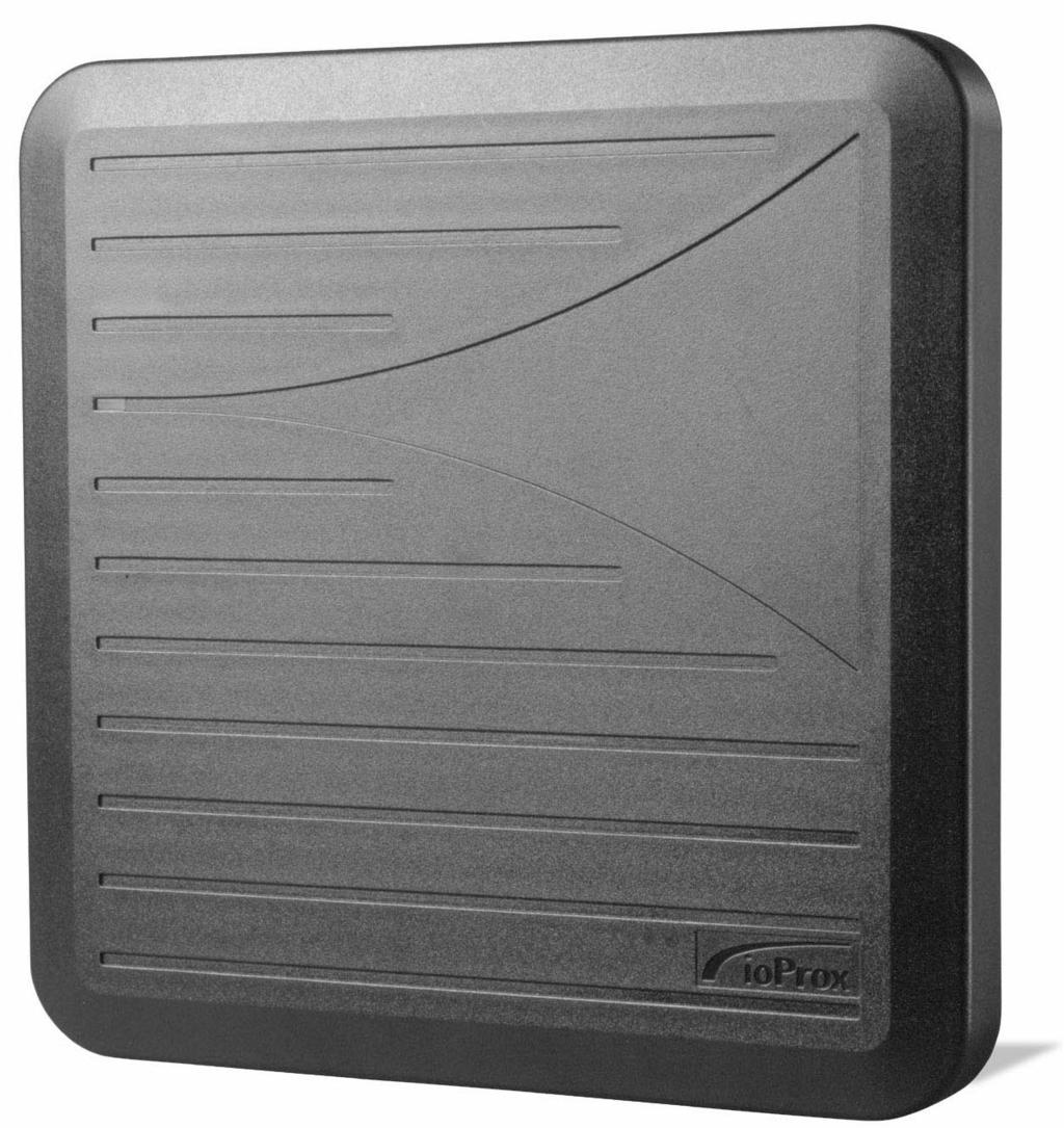
P600 IoProx Long Range Proximity Reader
|
|
|
- Oswin Hall
- 6 years ago
- Views:
Transcription
1 DN
2 Warning! This manual contains information on limitations regarding product use and function and information on the limitations as to liability of the manufacturer. The entire manual should be carefully read. Product names are trademarks or registered trademarks of their owners. No part of this publication may be reproduced in any form without permission from Kantech Systems. Kantech Systems Tel.: + 1 (978) Toll Free (US & Canada): Fax: + 1 (978) Web Site: techlink@tycoint.com 2002, Kantech Systems. All rights reserved. Specifications may be modified without notice. Trademarks of Kantech Systems. DN
3 Safety Instructions The P600 IoProx Long Range Reader is designed to be INSTALLED and MAINTAINED by SERVICE PERSONNEL ONLY. Service personnel must have appropriate technical training and experience necessary to be aware of the hazards to which they are exposed and of measures to minimize the danger to themselves or other persons. The Equipment is a FIXED Class III equipment designed for CONTINUOUS OPERATION. It shall be installed in NON HAZARDOUS LOCATIONS ONLY, OVERVOLTAGE CATEGORY II, and it shall be powered via a LIMITED POWER SOURCE as it is defined within the Clause 2.5 EN60950:2000. The equipment shall be interconnected with other equipment by using cables insulated with PVC, TFE, PTFE, FEP, neoprene or polymide and which are RATED for the intended environment. The ENCLOSURE of the P600 IoProx Long Range Reader must be secured to the building structure before operation. The connection to the mains supply must be made as per the local authorities rules and regulations. An appropriate disconnect device shall be provided as part of the building Installation; Where it is not possible to rely on the identification of the NEUTRAL in the AC MAINS SUPPLY, the disconnecting device shall disconnect both poles simultaneously (LINE and NEUTRAL). Regarding the power supply: It shall be PERMANENTLY CONNECTED, In European Union countries, it shall meet the applicable requirements of the Low Voltage Directive and protected, as per the EN60950 Standard, In all other countries, it shall be of an approved type acceptable to the local authorities. If during the installation, OPENINGS are made in the PLASTIC ENCLOSURE, it is the installer s responsibility to ensure that the same degree of protection for the ENCLOSURE as it has before will be provided, by the use of bushings, fittings, adequate sealant, etc. (These must be appropriate for the expected environmental conditions). Internal wiring shall be routed in a manner that prevents: Εxcessive strain on wires and on terminal connections, Loosening of terminal connections, Damage of conductor insulation. It is the end-user s and/or installer s responsibility to ensure that used batteries are disposed according to the waste recovery and recycling regulations applicable to the intended market. The intended to be used batteries shall be in full conformance with 91/157/EEC Directive. ATTENTION: THERE IS HIGH VOLTAGE (UP TO 900 VAC) BETWEEN SAFETY EXTRA LOW POWER CIRCUIT AND THE ANTENNA: RISK OF ELECTRIC SHOCK, DO NOT TOUCH BOTH CIRCUITS AT THE SAME TIME. DISCONNECT THE POWER WHEN SERVICING THE READER CIRCUIT. CE Compliance Notice for EN Please note that 18AWG shielded cable must be used to comply with EN
4
5 P600 IoProx Long Range Reader Table of Contents System Overview...1 Specifications... 1 Operations... 2 Installing the P600 Proximity Long Range Reader...3 Opening the Enclosure... 3 Setting the Data Format... 4 Installing the Strain Relief and Connecting Cables... 5 Mounting the P Installing the P600 on a Wall... 8 Installing the P600 on an Electrical Box... 8 Installing the P600 on an Electrical Post... 8 Installing the P600 on a Gooseneck... 9 Weatherproofing the P Wiring the P Wiring...11 Closing the Enclosure Applying the Power Testing Installation Notes and Guidelines Power Supply Installation Near Metal Radio Frequency Interference Transponder Type v
6 P600 IoProx Long Range Reader vi
7 Chapter 1 System Overview The P600 Long Range Reader is a self-contained and weather sealed proximity reader designed for outdoor and indoor use. The two-piece polycarbonate cover fits tightly over a foam gasket, offering security against weather. A cable fitting (strain relief) seals the cable entry. The reader uses a non-shielded 18AWG to 22 AWG cable. The P600 Long Range Proximity Reader can be powered from 12VDC to 28VDC. A bi-color LED and audible tone provide user feedback. A single dipswitch gives field configuration for Kantech Extended Secure Format (XSF) or 26-bit Wiegand data output format. A tamper switch alerts the host (controller) of intrusion. Closing the cover activates the tamper switch by pressing down the post on the lever of the switch. 1.1 Specifications Typical read range...up to 29" (73 cm) Input voltage...12 to 28 VDC Maximum peak current...1a Dimensions (H x W x D) in x x 1.25 Dimensions (H x W x D) cm x 28.5 x 3.15 Color...Black Transmit frequency KHz LED indicator...bicolor (red and green) Piezo buzzer...integrated Tamper switch...integrated (normally closed when secured) Operating temperatures...-35ºc to 65ºC (-30ºF to 150ºF) Reader format...26-bit Wiegand or Kantech XSF format (field selectable) Cable...18 AWG or 22 AWG wires (For details, refer to Table Cable Length and Reading Range on page 5) Compatible cards...p10shl, P20DYE, P30DMG, P40KEY. Certification...FCC Part 15, Class B; ICES-003; UL294; CE approved (EN 55022, EN , EN 60950) Note For best reading results it is strongly recommended to use 18 AWG non-shielded cable such as BELDEN 5304UE (six wires) or BELDEN 5306UE (eight wires) when the tamper switch is used. Best reading results are obtained when a 12 VDC power supply is used. System Overview 1
8 1.2 Operations At power-up the P600 emits beeps and flashes the LED. The number of beeps and flashes depends on the dipswitch mode selection, Kantech XSF or Wiegand. If the reader is set to 26-bit Wiegand, it sounds four beeps and the LED flashes three times. If it is set to Kantech XSF format, it sounds two beeps and the LED flashes two times. When a card is presented, the reader evaluates the card ID for a standard Kantech format. If the card is valid, the data are sent to the controller for user identification and a beep is heard while the LED turns solid green for a minimum of 1/4 second (extended duration depends on the controller setting). If permission is granted, the door unlocks. The next card can be read only after the current card is moved out of the field (36 inches minimum from the reader) for a period of at least one second. Note The best read range is achieved with P10SHL cards; there will be a reduced read range with P20DYE, P30DMG and P40KEY cards. 2 System Overview
9 Chapter 2 Installing the P600 Proximity Long Range Reader In choosing a location for mounting the reader, keep the following considerations in mind: no metallic and PC monitor should be near the P600 location (10 m (30 feet) minimum). The reader can be installed on: Awall, A single or double gang electrical box, An electrical post, A goose neck or pedestal. The P600 can be mounted and installed in seven easy steps: 1. Opening the enclosure, 2. Setting the required data format (Kantech XSF or 26-bit Wiegand), 3. Installing the strain relief and connecting the cable, 4. Mounting the reader to its location, 5. Closing the enclosure, 6. Powering up the power supply and the host (12 or 24VDC), 7. Verifying the reading with a transponder (card). 2.1 Opening the Enclosure It is easy to open and close the enclosure. Three sets of attachments allow you to open and close the casing as illustrated by Figure 1. Two hinges on the top of the unit that give an angular movement of 15º from the base, A notch on the bottom of the case that temporarily holds the cover over the base, Two screws that insure the robustness and seal of the enclosure. Installing the P600 Proximity Long Range Reader 3
10 To open the enclosure: 1. Unscrew the two screws at the bottom of the reader. STEP 1 STEP 2 STEP 3 Figure Opening the enclosure 2. Slightly open the cover from the bottom by gently prying it using a flat screwdriver at one of the screw position until the snap releases. 3. With your hand, pull the cover until it gets slightly over the base and then push it from bottom-up to release the top hinges. 2.2 Setting the Data Format Most of Wiegand interfaces use standard 26-bit data formats compatible with various controller brands. The Kantech Extended Secure Format (XSF) is proprietary and is supported by Kantech controllers only. Using the Kantech XSF provides increased security and guarantees against duplication of cards. The Kantech XSF is the default format. To set the data format: 1. To select the Kantech XSF format, set the communication mode dipswitch to XSF (lower position, toward the board edge side). WIEGAND26 ON C&K XSF 2. To select the 26-bit Wiegand format, set the dipswitch to Wiegand26 (upper position, toward the board components). 4 Installing the P600 Proximity Long Range Reader
11 2.3 Installing the Strain Relief and Connecting Cables The strain relief serves as a cable fitting. You can use either 18 AWG or 22 AWG wires. The cable does not need to be shielded and/or pair twisted. However, it is strongly recommended to use an 18 AWG non-shielded 6-wire cable such as BELDEN 5304UE and 8-wire cable such as BELDEN 5306UE. The following table shows how the reading distance can be affected by the wire gauge and the cable length. Cable Length Reading Range (18 AWG) Reading Range (22 AWG) 50 feet (15 m) 29 inches (73 cm) 27 inches (68 cm) 100 feet (30 m) 28 inches (71 cm) 27 inches (68 cm) 500 feet (150 m) 24 inches (61 cm) 19 inches (48 cm) 1000 feet (300 m ) 22 inches (56 cm) 14 inches (35 cm) Table 1: Cable Length and Reading Range To install the strain relief and to connect cables: 1. Install the strain relief on the rear of the P600 (nut inside). 2. Feed the cable through the strain relief. 3. Connect the wires to the terminal strip with the minimum length necessary, without leaving extra loops of wire inside the reader housing. 4. Tighten the strain relief to secure the cable. Note Before closing the cover, refer to Weatherproofing the P600 on page 10. Installing the P600 Proximity Long Range Reader 5
12 6 Installing the P600 Proximity Long Range Reader
13 Chapter 3 Mounting the P600 Mount the base of the P600 that holds the electronics to the surface using the holes located on the base of the reader. There are holes corresponding to each type of installation. No drilling is required for most installation types, except for installation on an electrical post (refer to Installing the P600 on an Electrical Post on page 8). Use the appropriate holes for the selected type of installation: Wall mounting Post mounting Gooseneck mounting The following figure shows the location of all available installation holes. Figure Mounting Holes Note Before closing, refer to Weatherproofing the P600 on page 10. Mounting the P600 7
14 3.1 Installing the P600 on a Wall Wall mounting is preferably done onto a flat surface. There are 14 well distributed holes for easy installation on a wall. Caution! If you are mounting the reader on a brick wall, care should be taken not to force the screws in a manner to curve the casing. This could reduce the efficiency of the seal from the base to the top. No drill is required as a little pressure with a screwdriver or the screw will pierce any excess plastic left over. Refer to Figure 3.1 for all 14 A hole positions. 3.2 Installing the P600 on an Electrical Box For electrical box installation, there are 11 holes to satisfy the North American single and double gang box and the European single gang box. Refer to Figure 3.1 for the 11 B hole positions. 3.3 Installing the P600 on an Electrical Post Two U-bolts allow for installation on an electrical post. There are four oblong mounting areas (two per U-bolts) to accommodate three different post diameters with pre-positioned holes to satisfy U-bolts of 1 ½ (3.8 cm), 1 ¼ (3.15 cm) and 1" (2.5 cm). Refer to Figure 3.1 for all C hole positions. The suggested installation is to bring the top of the PVC post up to the strain relief and run the cable through the strain relief and the post. For mounting the P600 on an electrical post, refer to Electrical post mounting on page 9. 8 Mounting the P600
15 In order to install the U-bolts, you will need to drill a 5/16 (8mm) hole using the pre-positioned holes. Depending on the U-bolt used you may need to cut the length of it in order to meet the inside case room. Figure Electrical post mounting 3.4 Installing the P600 on a Gooseneck The gooseneck installation provides 4 mounting holes to match the IPEX MH-U-25 (Part number 77961) post base. The post base combined with the 90º post IPEX EE2590 (Part number 69084) complete the gooseneck installation. Note Use 3/16 (4.75 mm) diameter (¼ (6.38 mm max), ¾ (19 mm) long ((1 ¼ (3.15 cm) max)), pan head screw with locking nut. Use security screws to prevent vandalism Mounting the P600 9
16 The next figure shows to install the P600 on a gooseneck (holes marked D ). 3.5 Weatherproofing the P600 Figure Goose neck installation A proper sealing of the reader ensures weatherproofing. The P600 is a sealed equipment but some holes will be created at installation time giving openings allowing water to enter. The installer must pay attention to all new openings. To weatherproof the P600: 1. Fill holes with silicone before tightening screws. 2. Use the liquid tight strain relief and seal the nut with silicone prior to tightening it. 3. Screw in the two screws while keeping the cover as close to the back as possible. 10 Mounting the P600
17 Chapter 4 Wiring the P600 Warning! Before wiring the unit, ensure that all power from host and power supply are off (including the battery backup supplies). The following sections show step-by-step the recommended installation of a P600 with any standard host and a KT-PC4204 power supply. 4.1 Wiring Perform the following steps to complete wiring: 1. Install the KT-PC4204 as per the recommendations (Kantech Installation Instructions DN1246). Note that the KT-PC4204 is strictly used as a power supply and no other equipment except the transformer and the battery should be connected to it. Do not power it up yet. 2. Install the host as per the manufacturer s recommendations. Do not power it up yet. Figure Host and Power Supply Wiring Wiring the P600 11
18 3. Connect the negative side of the power supply from P600 GROUND to the KT-PC4204 GND. 4. Connect the positive supply from P600 SUPPLY to KT-PC4204 AUX. 5. Wire jump KT-PC4204 AUX to KT-PC4204 RED. 6. Connect a wire from the KT-PC4204 GND to the Host GND (must be a relatively short distance. 7. Connect the P600 Data 0 (Green), Data 1 (White), LED (Brown) and Buzzer (Piezo) (Blue) to Host Data 0, Data 1, LED and Buzzer terminals respectively. 8. If used, connect the tamper switch from P600 both tamper wires to Host corresponding terminals. 9. Adjust the P600 dipswitch for the communication format required (XSF = ON, WIEGAND26 = OFF) (if not done already). 10. Close the P600 enclosure. 4.2 Closing the Enclosure To close the enclosure: 1. Slide the cover from top to bottom over the installed base until the cover hinges fit into the base openings. STEP 1 STEP 2 STEP 3 Figure Closing the enclosure 2. Push the cover to the base until they snap together, 3. Screw in the two screws while maintaining the cover as flush to the back of the base as possible. 4.3 Applying the Power 1. After all wiring is completed, apply power to the KT-PC4204 by connecting the battery leads to the battery, then connecting the AC transformer. 2. Apply power to the host by connecting the battery leads to the battery, then connecting the AC transformer. Note Use ONLY the supplier s recommended battery type. 12 Wiring the P600
19 4.4 Testing Test for read range with a valid Kantech proximity card (P10 SHL). It is important to understand that the Host must be configured in order to accept the data from the reader. If the reader does not work properly, refer to Troubleshooting on page 17. Wiring the P600 13
20 14 Wiring the P600
21 Chapter 5 Installation Notes and Guidelines Various factors may affect the read range of the P600: Installation near metal, Radio frequency interference, Transponder type. The following sections will enable you to find solutions should the read range of the P600 be reduced. 5.1 Power Supply The recommended power supply is 12VDC, nominal 1.5A current rating, linear regulated with 7Amps/hour battery backup. The P600 can also work with a power supply up to 28VDC but the reading distance will decrease. Note The above are recommended installation procedures. All local, state and national electrical codes have precedence. Warning!Do not use a switching power supply: This type of supply does not provide adequate response to rapid transient current loads and also generates radio frequency (RF) interference in the same band where the reader receives data, This type of power supply may generate enough noise to be transmitted or conducted to the P600. This may interfere with the reception of a card signal as some switching power supplies are not suitable to provide adequate regulation to the P600 reader. 5.2 Installation Near Metal The P600 generates a electromagnetic field on all sides of the reader. Any metal that conducts electricity, especially metal that contains iron, steel, aluminium or copper will interfere with the field and will reduce the effective read range (this will happen even if the metal is behind the reader). Note The typical read range specification refers to operation without metal in the vicinity of the reader. The distance will be reduced if metal is installed nearby. Read range will be reduced if the P600 is located on metal surfaces or in vicinity of metal objects. The amount of reduction will depend on the amount of metal and the distance between the P600 and the metal. Metal near the reader absorbs energy from the reader excite field and affects the signal being received from the card by re-directing excite field transmissions into the receiver circuitry. Installation Notes and Guidelines 15
22 If the read range is reduced: Move the reader away from the metal objects to reduce energy loss. Try to limit the amount of metallic materials near the P600. Use a plastic electrical box and/or PVC electrical post and/or PVC gooseneck if possible. Avoid installing conduit and other metal hardware within four inches (10 cm) of the back of the reader or closer than ten inches (25 cm) from large metal surfaces. Put a non-metallic spacer between the reader and the metal object. 5.3 Radio Frequency Interference Motors and electronic devices generate RF noise that may interfere with the reception of the signal from a transponder. The result of RF noise is typically a reduction of read range. The P600 is susceptible to RF interference, as are all devices that receive RF signals. The read range is affected by the amount interference (noise) in the area. Common sources of RF interference are: Power supplies, Electrical and electronic equipment, Some types of lightning, Computers and monitors, Motors and generators, HVAC compressors. If the read range is reduced: Move the reader to a location known to be free of interference Test read range from the new location to isolate RF interference. Do not mount the P600 within 15 feet (5 m) of any monitors (VDTs or CRTs). 5.4 Transponder Type The type of transponder used affects the read range of the P600. The various styles of KANTECH cards and transponders use different types of antennas. The antenna type will determine the read range for that type of transponder. The following table shows the difference in the read range depending on the card read. Card Type Read Range (Inches) Read Range (Cm) P10SHL clamshell cards inches cm P20DYE/P30DMG inches cm P40KEY inches cm Table 1: Read Range vs. Card Type 16 Installation Notes and Guidelines
23 Troubleshooting Warning! Troubleshooting should be performed by qualified service personnel only. Before calling the Technical support, verify the following: Reader doesn t read 1. Verify that no other proximity cards are in the reading field (up to 36 inches (91 cm) from the reader). 2. Is a linear voltage regulated power supply being used with a backup battery? (12V@1.5A). The use of switching power supplies is not recommended. 3. Is a DC common connected between the external power supply and the door controller? 4. Is the correct proximity card being used? (P10SHL, P20DMG, P30DMG, P40KEY). 5. Is the recommended cable being used? And is the maximum length respected? 6. Is the LED amber? If yes, there is not sufficient power for the reader. Verify the power supply and wiring. 7. Verify the voltage at the terminals RED BLK. It should measure between VDC for a 12V supply and VDC for a 24V supply. 8. Verify that no other proximity cards are in the reading field (up to 36 inches (91 cm) from the reader). 9. Is there ice buildup on the printed circuit or antenna posts? If yes, return the reader. Reader has reduced read range 1. Is a linear voltage regulated power supply being used with a backup battery? (12V@1.5A) The use of switching power supplies is not recommended. 2. Is the reader installed on a beam, pole, pedestal or other metallic material, which could cause interference? 3. Is there a computer monitor (CRT) within 15 feet (5 m)? Note also that dye sub cards (P20DMG, P30DMG) and keyfobs (P40KEY) will have less read range than their clamshell counterpart (P10SHL) because of their smaller antenna. 4. Is the reader concealed in a box, cabinet, or behind a wall, which may interfere? 5. Verify the voltage at the terminals RED BLK. It should measure between VDC. Though the reader works up to 27.6VDC, optimal performance is in the 12VDC range to accommodate the antenna tuning. 6. Is there a DC common GND connected between the power supply and the door controller? LED doesn t flash or change color upon a card approach 1. Verify that no other proximity cards are in the reading field (up to 36 from the reader). 2. Verify that the brown wire or LED terminal is connected to the door controller's output. 3. Verify that the door controller's output programming is ok. 17
24 4. The LED must turn green when connecting the BRN or LED terminal to the reader s ground. If not, return the reader. Reader BUZZER doesn t sound 1. Verify that the blue wire or Buzzer terminal is connected to the door controller's output. 2. Verify that the door controller's output programming is ok. 3. The BUZZER must be heard when connecting the BLU or Piezo terminal to ground. If not, return the reader Reader doesn't read correct card number 1. Verify that the XSF/W26 switch is in the correct position. 2. Verify that the door controller's reader type (XSF or Weigand 26 bits) is properly programmed. 3. Verify that the correct proximity card is being used (P10SHL, P20DMG, P30DMG, P40KEY). 4. Verify that there is communication between the reader and the door controller. Reader works intermittently 1. Is it working in a harsh environment such as machine shop or construction site? 2. Is there ice buildup on the printed circuit or antenna posts? If so, return the reader. 3. Is there water leakage or evidence of water on the printed circuit or antenna posts? If yes, return the reader. 4. Is the power supply dedicated? 5. Is the reader installed near an air conditioning or HVAC unit, which comes on (causing inductive kickback) at different times of day? 6. Is there an intercom unit located near the reader, whose wires or operation may interfere? 18
25
26 Kantech Systems Tel: +1(978) Toll Free: US & Canada: Fax: +1(978) Web Site: techlink@tycoint.com 2002, Kantech Systems. All rights reserved. Specifications may be modified without notice. Trademarks of Kantech Systems. Printed in USA DN
Installation Manual Rev E MaxiProx Wiegand Reader 5375A
 Installation Manual - 5375-900 Rev E MaxiProx Wiegand Reader 5375A _ http://www.prox.com MaxiProx Wiegand Reader Installation Manual 5375-900 REV E 1 of 10 MaxiProx System Overview The MaxiProx reader
MS-5000: MiniStar Reader
 The MS-5000 MiniStar Reader The MS-5000 MiniStar Reader is intended for installation in a single gang electrical "J-Box," in proximity applications where an unobtrusive reader is required. It can also
MS-7000: SuperStar Reader
 The MS-7000 SuperStar Reader The MS-7000 SuperStar Reader is intended for installation in proximity applications where an extended read range is required. The reader provides an audio beeper and a multi
FlexPass. ASR Long Range Reader. Installation Guide Jeronimo Road Irvine, CA July 16, 2007 Document Number K , Rev B
 9292 Jeronimo Road Irvine, CA 92618-1905 FlexPass ASR-620++ Long Range Reader Installation Guide July 16, 2007 Document Number K02021-000, Rev B FlexPass ASR-620++ Long Range Reader K02021-000 Rev. B Contents
MS-5000 MiniStar Reader. Quick Start Guide MS The MS-5000 MiniStar Reader. 1.0 Specifications
 The MiniStar Reader The MiniStar Reader is intended for installation in a single gang electrical "J-Box," in proximity applications where an unobtrusive reader is required. It can also be mounted directly
The Pyramid Series features five readers, each with its own unique characteristics, to meet virtually any requirements an end-user may have.
 Proximity Readers The Proximity line of OEM Proximity Readers can be used with virtually any manufacturer's access panel because the readers produce industry standard pass-through Wiegand (26-bit or custom
MS-3000 MicroStar Reader
 MicroStar Reader The MicroStar Reader The MicroStar Reader is intended for installation on a window mullion or a door frame, on or off metal, in proximity applications where an unobtrusive reader is required.
Ethernet Extender. EnviroNET 2100 Series. Quick Start Guide
 EnviroNET 2100 Series Ethernet Extender Quick Start Guide Important This is a Class A device and is intended for use in an industrial environment. It is not intended nor approved for use in a residential
USP-070-B08 USP-104-B10, USP-104-M10 USP-156-B10
 UniStream HMI Panel Installation Guide USP-070-B10, USP-070-B08 USP-104-B10, USP-104-M10 USP-156-B10 Unitronics UniStream platform comprises control devices that provide robust, flexible solutions for
Pyramid Series Proximity Readers
 The Proximity line of OEM Proximity Readers can be used with virtually any manufacturer's access panel because the readers produce industry standard pass-through Wiegand (26-bit or custom formats) or magnetic
MS-4000: ShootingStar Reader
 : ShootingStar Reader The ShootingStar Reader The ShootingStar Reader is intended for installation on a solid metal surface, in proximity applications where a vandal-proof reader is required. The reader
Indala Reader Installation Guide
 Indala Reader Installation Guide FCC This device complies with part 15 of the FCC rules. Operation is subject to the following two conditions: (1) this device may not cause harmful interference, and (2)
Installation Guide V290 (Color) This guide provides basic information for Unitronics LCD color touchscreen models V C30B and V T40B.
 This guide provides basic information for Unitronics LCD color touchscreen models V C30B and V T40B.") Vision OPLC Installation Guide V290 (Color) This guide provides basic information for Unitronics LCD color touchscreen models V290-19-C30B and V290-19-T40B. General Description Vision OPLCs are programmable
Vision OPLC Installation Guide V290 (Color) This guide provides basic information for Unitronics LCD color touchscreen models V290-19-C30B and V290-19-T40B. General Description Vision OPLCs are programmable
When any of the following symbols appear, read the associated information carefully. Symbol Meaning Description
 Uni-I/O Modules Installation Guide UID-0808R, UID-0808T, UID-1600,UID-0016R, UID-0016T Uni-I/O is a family of Input/Output modules that are compatible with the UniStream control platform. This guide provides
EL-ST100 KEYPAD CONTROLLER
 WIRING DIAGRAM EL-ST100 KEYPAD CONTROLLER WEATHER-PROOF STANDALONE ACCESS CONTROLLER WITH KEYPAD & PROXIMITY TECHNOLOGY Programming and Installation Manual NOTE: www.elock2u.com ICT at work! Version 3.6
Installation Manual Rev D MiniProx Readers - Wiegand 5365B and Clock and Data 5368B
 Installation Manual - 5365-902 Rev D MiniProx Readers - Wiegand 5365B and Clock and Data 5368B Web page, E-mail - www.prox.com MiniProx Reader Installation Manual 5365-902 REV D 1 of 7 MiniProx Reader
When any of the following symbols appear, read the associated information carefully. Symbol Meaning Description
 Uni-I/O Modules Installation Guide UID-0808THS Uni-I/O is a family of Input/Output modules that are compatible with the UniStream control platform. This guide provides basic installation information for
When any of the following symbols appear, read the associated information carefully. Symbol Meaning Description
 Uni-I/O Modules Installation Guide UIA-0402N Uni-I/O is a family of Input/Output modules that are compatible with the UniStream control platform. This guide provides basic installation information for
ZC-OH5 TAMPER-RESISTANT INDOOR/OUTDOOR HOUSING INSTRUCTION MANUAL FOR USE WITH GANZ ZC-D5000 SERIES MINIDOME CAMERAS
 ZC-OH5 TAMPER-RESISTANT INDOOR/OUTDOOR HOUSING INSTRUCTION MANUAL FOR USE WITH GANZ ZC-D5000 SERIES MINIDOME CAMERAS Please carefully read and observe all instructions and warnings contained in this manual
MAXIMA+ Series Rotary Level Indicator
 MAXIMA+ Series Rotary Level Indicator BinMaster: Division of Garner Industries 7201 N. 98th St., Lincoln, NE 68507 402-434-9102 email: info@binmaster.com www.binmaster.com OPERATING INSTRUCTIONS PLEASE
UniStream HMI Panel. CPU-for-Panel
 UniStream HMI Panel Installation Guide USP-070-B10,USP-104-B10, USP-156-B10 Unitronics UniStream platform comprises control devices that provide robust, flexible solutions for industrial automation. This
DC Outdoor Power Supply/Chargers
 DC Outdoor Power Supply/Chargers Installation Guide Models Include: WayPoint3 WayPoint7-2.5A @ 12VDC or 24VDC. - 6A @ 12VDC or 24VDC. - 115/230VAC input. - 115VAC input. WayPoint5 WayPoint7V - 4A @ 12VDC
Temperature. Power requirements. Weight. Dimensions
 Installing the Tracer Summit BMTX Building Control Unit Ordering numbers: BMTX001AAB000, BMTX001AAB010, BMTX001AAB001, BMTX001AAB011, BMTX001BAB000, BMTX001BAB010, BMTX001BAB001, BMTX001BAB011, BMTX001DAB000
When any of the following symbols appear, read the associated information carefully. Symbol Meaning Description
 Uni-I/O Wide Modules Installation Guide UID-W1616R, UID-W1616T Uni-I/O Wide is a family of Input/Output modules that are compatible with the UniStream control platform. Wide Modules are 1.5 times as wide
Installation Guide V290 (Color) This guide provides basic information for Unitronics LCD color touchscreen models V C30B and V T40B.
 This guide provides basic information for Unitronics LCD color touchscreen models V C30B and V T40B.") Vision OPLC Installation Guide V290 (Color) This guide provides basic information for Unitronics LCD color touchscreen models V290-19-C30B and V290-19-T40B. General Description Vision OPLCs are programmable
Vision OPLC Installation Guide V290 (Color) This guide provides basic information for Unitronics LCD color touchscreen models V290-19-C30B and V290-19-T40B. General Description Vision OPLCs are programmable
F1000 User's Manual. (Version: V1.01)
") (Version: V1.01) Contents Chapter 1 Overview... 2 Chapter 2 Installation... 3 2.1 Installation guide... 3 2.1.1 Installation position... 3 2.1.2 NEMA4 standard installation... 3 2.1.3 Environment precautions...
(Version: V1.01) Contents Chapter 1 Overview... 2 Chapter 2 Installation... 3 2.1 Installation guide... 3 2.1.1 Installation position... 3 2.1.2 NEMA4 standard installation... 3 2.1.3 Environment precautions...
Solar Combiner Enclosure
 Installation Instructions Solar Combiner Enclosure Catalog Numbers 1000-SB006, 1000-SB012 Topic Page Description 1 Important Safety Instructions 3 Nameplate Data 4 Planning for Installation 4 Install the
Power Supply and Fan Module Installation
 3 CHAPTER This chapter describes how to remove and install a new or replacement power supply or fan module in a Catalyst 3750-E or Catalyst 3560-E switch. See these sections: Installation Overview, page
MAXIMA + Series ROTARY LEVEL CONTROL
 Price $5.00 MAXIMA + Series ROTARY LEVEL CONTROL OPERATING INSTRUCTIONS PLEASE READ CAREFULLY Division of Garner Industries 7201 North 98th Street Lincoln, NE 68507-9741 (402) 434-9102 925-0268 Rev. A
This guide provides basic information for Unitronics Models 230/260/280/290 (Non-color Screens).
.") Vision OPLC Installation Guide Models 230/260/280/290 (Non-color Screens) This guide provides basic information for Unitronics Models 230/260/280/290 (Non-color Screens). General Description Vision OPLCs
Vision OPLC Installation Guide Models 230/260/280/290 (Non-color Screens) This guide provides basic information for Unitronics Models 230/260/280/290 (Non-color Screens). General Description Vision OPLCs
When any of the following symbols appear, read the associated information carefully. Symbol Meaning Description
 Uni-I/O Modules Installation Guide UIS-04PTN Uni-I/O is a family of Input/Output modules that are compatible with the UniStream control platform. This guide provides basic installation information for
Replacing the Power Supply
 APPENDIX B This appendix includes information on how to replace the power supply for the Cisco AS550XM universal gateway and contains the following sections: Safety Recommendations, page B-1 Required Tools
This simple chassis houses one media-converter module and features an external AC power supply and also a terminal block for DC power input.
 LMC5103A-R2 1-slot Multipower Desktop Chassis (Module Not Included) This simple chassis houses one media-converter module and features an external AC power supply and also a terminal block for DC power
Series Amp Pad Mount Quick Connect Input and Output Power Panels
 Series 300 2000-4000 Amp Pad Mount Quick Connect Input and Output Power Panels DANGER is used in this manual to warn of a hazard situation which, if not avoided, will result in death or serious injury.
Installation Instructions
 Installation Instructions (Cat. No. 1794-PS1) 1 2 3 4 5 7 6 Component Identification 1 Supply module 1794-PS1 2 Indicator 3 120/230V ac ground 4 120/230V ac common L2/N connections 5 120/230V ac power
AB-2D AB-2D SPEAKER A,B OR A+B SELECTOR INSTALLATION & OPERATION GUIDE
 M O D E L AB-2D AB-2D SPEAKER A,B OR A+B SELECTOR INSTALLATION & OPERATION GUIDE AB-2D Speaker/Amplifier Selector TABLE OF CONTENTS Introduction 1 Features and Benefits 1 Installation Considerations 3
FlexPass TM Advantage Series Proximity Plus TM ASR PowerProx TM Reader User Manual
 FlexPass TM Advantage Series Proximity Plus TM ASR-620++ PowerProx TM Reader User Manual FCC Compliance: This equipment has been tested and found to comply with the limits for a Class B digital device,
6222 Two Door Module Technical Operations Manual
 6222 Two Door Module Technical Operations Manual TABLE OF CONTENTS Specifications...3 Overview...4 Operations...5 Custom Access Mode...5 Standard Access Mode...5 Offline Access Mode...5 Offline Memory...5
Zartek. CDP-808 Two Button Wireless Intercom Installers Manual
 Zartek CDP-808 Two Button Wireless Intercom Installers Manual ZA-614 Two Button Gate station including power supply, relay board and external antenna ZA-613 Handsets with charger ZA-613-E Handsets with
Now with Picture Memory
 Intrasonic Technology, Inc. Color Video Door Phone / Intercom Installer s Manual Model No.V304KIT-R Now with Picture Memory Please read this manual carefully before the products are installed.technical
PanelView Plus/VersaView CE Terminals and Display Modules
 Installation Instructions PanelView Plus/VersaView CE Terminals and Display Modules (Catalog Numbers 2711P-xxxxxx, 6182H-xxxxxx) English Inside: Overview...2 For More Information...2 Modular Components...3
Power Supply Installation
 Power Supply Module Overview, on page Installation Guidelines, on page 4 Installing or Replacing an AC Power Supply, on page 6 Installing a DC Power Supply, on page 7 Finding the Power Supply Module Serial
Your Global Flow Control Partner. Series 50 Valve Status Monitor Operation and Maintenance Manual
 Your Global Flow Control Partner Series 50 Valve Status Monitor Table of Contents 1. Definition of Terms... 2 2. Safety... 2 3. Storage... 3 4. Commissioning... 3 4.1. Mounting your VSM... 3 4.2. Wiring
Infosystem Remote Touchscreen Installation Instructions
 Infosystem Remote Touchscreen Installation Instructions DOC. #569102100 A 7/30/04 PRINTED IN U.S.A. Regulatory Compliance Safety This device has been tested and found to be in compliance with the requirements
Clipsal Bus Couplers. Two Channel (SLC5102BCLEDL) and Four Channel (SLC5104BCL) for Use with C-Bus Wired Systems
 and Four Channel (SLC5104BCL) for Use with C-Bus Wired Systems") Clipsal Bus Couplers Two Channel (SLC5102BCLEDL) and Four Channel (SLC5104BCL) for Use with C-Bus Wired Systems Instruction Bulletin Retain for future use. Clipsal Bus Couplers 63249-420-236A2 Instruction
Clipsal Bus Couplers Two Channel (SLC5102BCLEDL) and Four Channel (SLC5104BCL) for Use with C-Bus Wired Systems Instruction Bulletin Retain for future use. Clipsal Bus Couplers 63249-420-236A2 Instruction
Operating instructions. Switching amplifier DN0210 DN / / 2015
 Operating instructions Switching amplifier DN0210 DN0220 UK 80011079 / 00 01 / 2015 Contents 1 Preliminary note...4 1.1 Symbols used...4 1.2 Warning signs used...4 2 Safety instructions...5 2.1 General...5
InView Marquee Message Display
 Installation Instructions InView Marquee Message Display Introduction These instructions show how to change the serial address and how to mount InView series signs with NEMA Types 4, 4X, and 12 enclosures.
60W Power over Ethernet Waterproof Adapter PoE IEEE BT Single Port Injector for Outdoor Application
 WWW.PHIHONG.COM 60W Power over Ethernet Waterproof Adapter PoE IEEE BT Single Port Injector for Outdoor Application Features Compliant with the IEEE802.3bt Standard Non-Vented Case with Mounting Bracket
Adapter Kit for PanelView 1200/1200e Touch Screen Terminal Cutout
 Installation Instructions Adapter Kit for PanelView 1200/1200e Touch Screen Terminal Cutout Catalog Numbers 2711-NR5T, 2711P-RAT12E2 Topic Page About This Publication 1 Important User Information 2 About
Series Amp Quick Connect Input and Output Power Panels
 Series 300 1200-1600 Amp Quick Connect Input and Output Power Panels DANGER is used in this manual to warn of a hazard situation which, if not avoided, will result in death or serious injury. WARNING is
Recommended Practices for Installation For EC Directive 2004/108/EC Relating to EMC Supplement to Installation and Operating Manual
 Recommended Practices for Installation For EC Directive 2004/108/EC Relating to EMC Supplement to Installation and Operating Manual 6/09 MN1383 Any trademarks used in this manual are the property of their
Line reactors SINAMICS. SINAMICS G130 Line reactors. Safety information 1. General. Mechanical installation 3. Electrical installation
 Safety information 1 General 2 SINAMICS SINAMICS G130 Mechanical installation 3 Electrical installation 4 Technical specifications 5 Operating Instructions Control version V4.7 04/2014 A5E00331462A Legal
C5C Cross-Connect System
 C5C Cross-Connect System I N S T A L L A T I O N I N S T R U C T I O N High-Density Connection Blocks 1.0 General Product Information The C5C cross-connect system is comprised of a high-density connection
Vision OPLC. General Description. Standard Kit Contents. Installation Guide Vision120. This guide provides basic information for Unitronics Vision120.
 Vision OPLC Installation Guide Vision120 This guide provides basic information for Unitronics Vision120. General Description V120 OPLCs are micro-oplcs, rugged programmable logic controllers that comprise
When any of the following symbols appear, read the associated information carefully. Symbol Meaning Description
 Vision OPLC V350-35-R34/V350-J-R34 Installation Guide The Unitronics V350-35-R34/V350-J-R34 offers the following onboard I/Os: 22 Digital Inputs, configurable via wiring to include 2 Analog and 3 HSC/Shaft-encoder
OPLC Installation Guide
 Samba OPLC SM35-J-R20/SM43-J-R20 SM70-J-R20 SM35-J-T20/SM43-J-T20 SM70-J-T20 OPLC Installation Guide 12 Digital Inputs, include 1 HSC/Shaft-encoder Input, 2 Analog inputs (only when the digital inputs
REX F-0-9 Standalone or Access Controller
 REX F-0-9 Standalone or Access Controller Power supply The controller need s external power supply to operate. The Spider W40 power supply is sufficient to power two controllers and two 12V electric strikes
Installation Note for the Cisco ME 3800X and ME 3600X Switch Power Supply and Fan Modules
 Installation Note for the Cisco ME 3800X and ME 3600X Switch Power Supply and Fan Modules This document provides the installation and removal instructions for the AC and DC input power supply and fan modules
High Speed Remote I/O Module
 High Speed Remote I/O Module EXF-RC15 The Unitronics EXF-RC15 is a High Speed Remote I/O Module that offers three High Speed Counter inputs and four high speed outputs. Overall, the EXF-RC15 offers 9 digital
Installing a Power over Ethernet injector
 Installing a Power over Ethernet injector AlphaEclipse StreetSmart and RoadStar signs The instructions in this document explain how to install/replace a Power over Ethernet (PoE) injector in a StreetSmart
Operating instructions. Speed monitor D / / 2014
 Operating instructions Speed monitor D200 80005257 / 00 05 / 2014 Contents 1 Preliminary note...4 1.1 Symbols used...4 1.2 Warning signs used...4 2 Safety instructions...5 2.1 General...5 2.2 Target group...5
Chameleon Stand-alone
 Quick Installation Guide Installation and Commissioning Chameleon Stand-alone Power Supply Module, 48 VDC, 650W, HE, IP65 Low Power Outdoor Applications 356849.03 Introduction Warnings..., page 3 Tools
NCH-1000 (Multiple Breaker Types) Installation Instructions
 Installation Instructions") 20M1 12345678 NCH-1000 (Multiple Breaker Types) Installation Instructions DOC. #560502100 C 7/30/04 PRINTED IN U.S.A. Regulatory Compliance Safety This device has been tested and found to be in compliance
20M1 12345678 NCH-1000 (Multiple Breaker Types) Installation Instructions DOC. #560502100 C 7/30/04 PRINTED IN U.S.A. Regulatory Compliance Safety This device has been tested and found to be in compliance
The identified danger could cause physical and property damage.
 Samba OPLC SM35-J-T20 Installation Guide The Unitronics SM35-J-T20 offers the following onboard I/Os: 12 Digital Inputs, configurable via wiring to include 2 Analog and 3 HSC/Shaft-encoder Inputs 8 Transistor
Model 2460-KIT. Screw Terminal Connector Kit. Description / September 2014 *P * 1
 Keithley Instruments 28775 Aurora Road Cleveland, Ohio 44139 1-800-935-5595 http://www.keithley.com Model 2460-KIT Screw Terminal Connector Kit Description The Model 2460-KIT Screw Terminal Connector Kit
Girard Awnings R ACMC Motor Controller (Last revised on May 10, 2008) A Visionary Awning Control by
 A Visionary Awning Control by") Girard Awnings R ACMC Motor Controller (Last revised on May 10, 2008) R A Visionary Awning Control by Girard AC Motor Controller Installation Guide ACMC Revision 2.08 May 10, July 2008 ACMC Installation
Girard Awnings R ACMC Motor Controller (Last revised on May 10, 2008) R A Visionary Awning Control by Girard AC Motor Controller Installation Guide ACMC Revision 2.08 May 10, July 2008 ACMC Installation
AR10S-MF AR11S-MF AR40S-MF AR41S-MF Installation manual for mounting and connecting. Siemens AB. Version 5.0 A Security Products
 AR10S-MF AR11S-MF AR40S-MF AR41S-MF Installation manual for mounting and connecting Version.0 06.09.2013 Security Products Copyright Copyright Technical specifications and availability subject to change
To connect the AC adapter:
 Replacing the AC Adapter Replacing the AC Adapter 3 Plug the power cord into a wall outlet. The power indicator turns on. To connect the AC adapter: Connect the power cord to the AC adapter. Power indicator
UniStream CPU-for-Panel
 UniStream CPU-for-Panel Installation Guide USC-P-B10 Unitronics UniStream platform comprises control devices that provide robust, flexible solutions for industrial automation. This guide provides basic
PS/IO Circuit Board Retrofit
 S&C 6800 Series Automatic Switch Controls PS/IO Circuit Board Retrofit Table of Contents Section Page Introduction Qualified Persons.... 2 Read this Instruction Sheet.... 2 Retain this Instruction Sheet....
EX-RC1 Remote I/O Adapter
 EX-RC1 Remote I/O Adapter The EX-RC1 interfaces between Unitronics Vision OPLCs and remote I/O Expansion Modules distributed throughout your system. The adapter is connected to a PLC via CANbus. Each adapter
IO-AO6X I/O Expansion Module 6 Isolated Analog Outputs
 IO-AO6X I/O Expansion Module 6 Isolated Analog Outputs The IO-AO6X is an I/O Expansion Module that can be used in conjunction with specific Unitronics OPLC controllers. The module offers 6 12-bit isolated
Quick Start Installation Guide
 RM-iCLASS Series Quick Start Installation Guide Version C0 Document Part Number UM-208 June 2009 OVERVIEW The RM-iClass Quick Start Installation Guide provides a summary of installation and connection
The power behind competitiveness. Delta Infrasuite Power Management. Power Distribution Unit. User Manual.
 The power behind competitiveness Delta Infrasuite Power Management Power Distribution Unit User Manual www.deltapowersolutions.com Save This Manual This manual contains important instructions and warnings
2 Mesa Ethernet Dock User s Manual
 owner s manual Mesa Ethernet Dock The Mesa Ethernet Dock is an optional accessory that provides an ethernet port for networking, power input jack, USB client port, and a mounting station for the Mesa Rugged
Vision OPLC V TR6/V350-J-TR6
 Vision OPLC V350-35-TR6/V350-J-TR6 Installation Guide The Unitronics V350-35-TR6/V350-J-TR6 offers the following onboard I/Os: 8 Digital Inputs, configurable via wiring to include 2 Analog (current/voltage)
MCH WIRE HARNESS WITH QUICK DISCONNECT REPLACEMENT Initial Release 1/31/2013
 1. Table of Contents 1. Table of Contents Page 1 2. Remove Failed MCH-103.2 Page 1 3. Install MCH-103.2 to MCH-102NW Page 2 4. Install NC3FX-HD to MCH-103.2 Page 3 5. Install MCH-103.2 Battery Terminal
QuickTouch (QT4) Owner s Manual
 Owner s Manual") QuickTouch (QT4) Owner s Manual 4-Function Hand-Held Wireless Remote Control IMPORTANT SAFETY INSTRUCTIONS READ AND FOLLOW ALL INSTRUCTIONS SAVE THESE INSTRUCTIONS Table of Contents SECTION I. APPLICATION...
QuickTouch (QT4) Owner s Manual 4-Function Hand-Held Wireless Remote Control IMPORTANT SAFETY INSTRUCTIONS READ AND FOLLOW ALL INSTRUCTIONS SAVE THESE INSTRUCTIONS Table of Contents SECTION I. APPLICATION...
TraceTek Leak Detection Master Module Installation Instructions TOOLS REQUIRED STORAGE
 TTDM-128 TraceTek Leak Detection Master Module Installation Instructions TRACETEK APPROVALS AND CERTIFICATIONS TYPE NM General Signaling Equipment 76LJ GENERAL INFORMATION Please read these instructions
Installation Instructions. Product Summary. Installation Guidelines. Tools and Equipment Needed. Table 1. Touchpad Power Usage
 Document Number: 466-1759 Rev. B August 2000 6 A I J 5 O I J A 9 A A O B B 0 A ) M = O )!, A = O 5 EA J 2 = C A H * " # $. A = J K H A I 5 O I J A A K + % & ' 5 J = J K I EC D J I * O F = I I, Installation
VIS-3102 Installation Manual
 Access Control Black with Clear Border Card Reader Only Compatible with Wiegand 26 and 34 Bit VIS-3102 Installation Manual User Manual COPYRIGHT 2015 Visionis Technology. ALL RIGHTS RESERVED. Any and all
EMC Installation Guide
 A P P E N D I X B EMC Installation Guide General Product Philosophy Meeting requirements for electromagnetic compatibility (EMC) compliance will require specific measures to be taken during installation
ATP1000 Touchpad/Display Installation Instructions
 ATP1000 Touchpad/Display Installation Instructions Product summary The ATP1000 lets you control all programming and operation of compatible security systems (see the Specifications section). The large
SAVE THESE INSTRUCTIONS
 OUTDOOR HARDWIRE INSTALLATION INSTRUCTIONS Please read and save these instructions. Read carefully before using product. Protect yourself and others by observing all safety information, warnings and cautions.
Please Read Instruction Carefully Before Installation! Figure 1: A/CO2-DUCT
 Installation and Operation Instructions A/CO2-DUCT Series Please Read Instruction Carefully Before Installation! Figure 1: A/CO2-DUCT PRECAUTIONS REMOVE POWER BEFORE WIRING. NEVER CONNECT OR DISCONNECT
Installing and Cabling Flexi Zone Micro High Power 2x20 W BTS DN Issue 02 Approval Date yyyy-mm-dd
 Nokia Networks Installing and Cabling Flexi Zone Micro High Power 2x20 W BTS DN09229011 Issue 02 Approval Date yyyy-mm-dd Installing and Cabling Flexi Zone Micro High Power The information in this document
Indoor/Outdoor Proximity Reader and Keypad with 10cm (4in) Read Range
 Read Range") Indoor/Outdoor Proximity Reader and Keypad with 10cm (4in) Read Range Stand alone CR-R885-SB Installation and Operating Instructions V1.1 TABLE OF CONTENTS Installation... 2 Mounting and Wiring... 2 Mounting
Indoor/Outdoor Proximity Reader and Keypad with 10cm (4in) Read Range Stand alone CR-R885-SB Installation and Operating Instructions V1.1 TABLE OF CONTENTS Installation... 2 Mounting and Wiring... 2 Mounting
Installation Instructions for the AUTOcard-SA System
 Installation Instructions for the AUTOcard-SA System IMPORTANT NOTICE The AUTOcard-SA system is a very reliable and easy to use system. However, damage could occur if it is installed incorrectly. In particular,
When any of the following symbols appear, read the associated information carefully. Symbol Meaning Description
 Uni-I/O Wide Modules Installation Guide UIS-WCB1 Uni-I/O Wide is a family of Input/Output modules that are compatible with the UniStream control platform. Wide Modules are 1.5 times as wide as Uni-I/O
M250 (M LL) Safety
 Safety") M250 SAFETY M250 (M250-60-2LL) Safety Important Safety Information This document contains important instructions to use during installation of the Enphase M250 Microinverter. To reduce the risk of electrical
M250 SAFETY M250 (M250-60-2LL) Safety Important Safety Information This document contains important instructions to use during installation of the Enphase M250 Microinverter. To reduce the risk of electrical
Installation Notes TII Model 341 Protector
 Installation Notes TII Model 341 Protector (ATT-IS PEC 32918) for MERLIN Communications System In Range Out of Building (IROB) Station Installation By Trained Technician Only WARNING: Failure to follow
IF-80x Outdoor Terminal
 95-10330_IF-800 V2016-10-20 Outdoor Terminal IF-80x Outdoor Terminal 1 IF-800 Outdoor / IF-801 We are pleased that you have decided to use a terminal of the IF-80x series for recording access data. Scope
Operating and Installation Manual. EASYLAB Expansion modules Type EM-TRF for 230 V AC mains voltage
 Operating and Installation Manual EASYLAB Expansion modules Type EM-TRF for 230 V AC mains voltage Type EM-TRF-USV for 230 V AC mains voltage; provides uninterruptible power supply (UPS) The art of handling
*520886* IntelliTouch Pool & Spa Control System MobileTouch Wireless Controller. User s and Installation Guide. P/N Rev A
 pool/spa control system IntelliTouch Pool & Spa Control System MobileTouch Wireless Controller User s and Installation Guide P/N 520886 - Rev A *520886* i MobileTouch Wireless Controller kit contents The
22 Digital Inputs, including 2 Analog, 2 HSC/Shaft-encoder inputs 16 Transistor Outputs
 Vision PLC+HMI V130-33-T38/V130-J-T38 V350-35-T38/V350-J-T38 V430-J-T38 Installation Guide 22 Digital Inputs, including 2 Analog, 2 HSC/Shaft-encoder inputs 16 Transistor Outputs General Description All
*Approved by CSA for non-hazardous locations (Group Safety Publication IEC Third Edition).
.") PowerCore Model MPC-20 Installation Manual *Approved by CSA for non-hazardous locations (Group Safety Publication IEC 61010-1 Third Edition). Products covered in this document comply with European Council
PowerCore Model MPC-20 Installation Manual *Approved by CSA for non-hazardous locations (Group Safety Publication IEC 61010-1 Third Edition). Products covered in this document comply with European Council
INSTRUCTION MANUAL DISTRIBUTION UNIT. Please read this manual thoroughly before use, and keep it handy for future reference.
 INSTRUCTION MANUAL DISTRIBUTION UNIT Please read this manual thoroughly before use, and keep it handy for future reference. ISSUE 1 May 2006 LIMITATION OF LIABILITY THE INFORMATION IN THIS PUBLICATION
Industriefunkuhren. Technical Manual. Signal Converter. for DIN Rail Mounting Series 4800xx-yy ENGLISH
 Industriefunkuhren Technical Manual Signal Converter for DIN Rail Mounting Series 4800xx-yy ENGLISH Version: 01.01-19.07.2007 2 / 23 Signal Converter 4800 - V01.01 INPORTANT NOTES Downloading Technical
Component identification
 IO-ATC8 I/O Expansion Module 8 Analog/Thermocouple Inputs The IO-ATC8 is an I/O Expansion Module that can be used in conjunction with specific Unitronics OPLC controllers. The module offers 8 inputs that
Installation Instructions
 Installation Instructions (Cat. No. 1794-TBN) 6 1 5 9 4 2 3 10 6 7 8 Component Identification 1 Female flexbus connector 2 Terminal base unit (1794-TBN) 3 Male flexbus connector 4 Keyswitch Set to the