ISAIX16 ISA Bus Isolation Extender. ISAIX16 ISA Bus Isolation Extender. User s Manual Rev E. User s Manual Rev E
|
|
|
- Johnathan Stevens
- 5 years ago
- Views:
Transcription
1 ISAIX16 ISA Bus Isolation Extender ISAIX16 ISA Bus Isolation Extender User s Manual Rev E User s Manual Rev E
2 PREFACE ISAIX16 is a 16 bit Industrial Standard Architecture (ISA) bus isolation extender. It allows ISA adapter boards to be added or removed from the ISA system bus without having to power down the system. It offers time and labor cost savings in product development and production board testing. It also serves to protect the motherboard from being damaged during testing. Operation of the ISAIX16 extender can be controlled by on-board toggle switch or by external TTL input signal. User is required to provide initialization routines to restore the state of the board under test during successive testing. Product Options: -T for additional connector at right angle. Related Products: ISASX2 ISABK1 ISA wearout Extender. ISA Tie down bracket. (C) Copyright 1999, Adex Electronics. This manual is copyrighted. All rights reserved. No part of this document may be reproduced, copied, translated or reduced by any means, without permission given beforehand in writing from Adex Electronics. Made in USA. Rev E 1/1999 ISAIX16 is a trademark of Adex Electronics. ISA and Industrial Standard Architecture are trademarks of IBM Corp. All other products mentioned in this manual are trademarks of their respective manufacturers TABLE OF CONTENTS Title Page Product Specifications and Features 4 ISAIX16 Operating Instructions 5 Fuse and Header Definition 6 ISAIX16 Component Side Outline 8 ISAIX16 Solder Side Outline 9 Theory of Operation 10 Local and External Control 11 On-Board Toggle Switch Operation 11 External Toggle Switch Operation 12 External Logic Control Operation 12 Voltage Margin, Current Measurement and External Power Source 13 Troubleshooting and Self Service 14 Board Initialization 16 Mounting of Bus Isolation Extender 17 Appendix 19 Using the Parallel Port as External TTL Control 20 ISA Bus Pinout 22 Warranty 24
3 Product Specifications: Bus: ISA (Industrial Standard Architecture) 16 bit bus. Power: Control: Signal Delay: Environment: +5V with 4 amp slow blow plug fuse. -5V with 1.6 amp slow blow plug fuse. +12V with 1.6 amp slow blow plug fuse. -12V with 1.6 amp slow blow plug fuse. Plus short circuit sensing logic on +5 and +12V. Single toggle switch or external TTL controls. Less than 500 picosecond (250 picosecond max. through the buffer) degree C (operating and storage). Dimension: Length 7.2 inches; Height 5.2 inches; Width 0.6 inches (Not including bracket). Product Features: Total power and signal isolation. No disturbance to the system bus during bus isolation and reconnection. Less than 500ps signal delay (isolation buffer + trace delay). Minimum voltage drop. Single switch operation or external TTL control signals. Voltage margin and current measurement. Over voltage and over current protection on power lines. Pluggable fuse allows easy replacement and change to other types and values of fuses. Fused power status green LED indicators. Short ckt sensing on +5 and +12V with auto power shut off. Reset pulse generation during power on. Flashing operating red status LED. Two-tone adjustable volume speaker for board status. Header pins for logic analyzer hook up. Supports low cost wearout extender. Optional right angle extender connector. Durable extender connector. Quality multilayer construction. ISAIX16 OPERATING INSTRUCTIONS 1. Insert the extender into an ISA expansion slot on an ISA motherboard. Secure the extender to the system enclosure with mounting bracket. 2. Power up the system, SW1 switch can be in either position, all green LEDs should light to show the state of the fused power. 3. Test the extender by switching the SW1 switch up and down. The red LED should be flashing with SW1 in up position, indicating bus connection. The speaker should also buzz about once per second. Adjust the volume of the speaker via the trim pot by the speaker. 4. Add or remove add-on boards to the extender only when the SW1 switch is in down position, the red LED is not flashing and the speaker is not buzzing (bus isolated). 5. Run test to the add-on boards with SW1 switch in the up position.. 6. To make current measurements without the fuse, remove the corresponding plug fuse and place an ampere meter across pin 1 and pin 3 of the fuse socket pins. To make measurement with the fuse, insert fuse at pin 2 and pin 4 of the socket pins, and connect the ampere meter across pin 1 and pin 4 of the fuse socket pins. 7. To make voltage margin tests without the fuse, remove the corresponding plug fuse and connect external voltages to pin 3 of the socket pin and connect external ground to system ground. To make voltage margin with the fuse; move fuse to pin 2 and pin 4 of the socket pins and connect external voltage to pin 4 of the socket. Warning! Pin 1 of the fuse sockets should not be connected, because they are tied directly to the system power. 8. The green LEDs at the upper right hand corner indicate the status of the fused power. If not lit, check the corresponding fuses and replace them accordingly. 9. To remove the adapter boards from the extender, one should be careful not to lift the extender out of its system expansion slot. Keep the extender down while removing the adapter board and make sure the extender is turned off
4 Fuse Socket W1 +5V W2-5V W3 +12V W4-12V W6, Speaker Jumper FUSE and PIN HEADER DEFINITION 4 EXTERNAL POWER 3 FUSED POWER 2 1 SYSTEM POWER Jumper in - Speaker will buzz at approximately once per second during normal operation while bus signal and power is fully connected. It will also generate a continuous tone if logic detects a short circuit condition. Jumper out - Speaker will not buzz during normal operation, but will still generate a continuous tone if logic detects a short circuit condition. To adjust the volume of the speaker, turn the trim pot by the speaker. Turn counter clockwise to increase the sound and turn clockwise to decrease the sound. W7 Pin Headers #Power_Control (Internal) 2 +5V 3 #Signal_Control (External Input, Low enable) 4 Key 5 #Power_Control (External Input, Low enable) 6 Gnd 7 Gnd 8 Power_Control (External Input, High enable) 9 LED- 10 LED+ # indicates low active input. Pin 1 and pin 3 are jumped together in default to allow single toggle switch operation, which both power and bus signals are turned on together. User may connect an external toggle switch to pin 5 or an external TTL high signal to pin 8 to control the board. To control the bus signals separately from the bus power, remove the jumper at pin 1 and pin 3 and connect external TTL control at pin 3. Power should be connected first, then the bus signals. The on-board toggle switch should be at down (off) position, if external TTL control is used


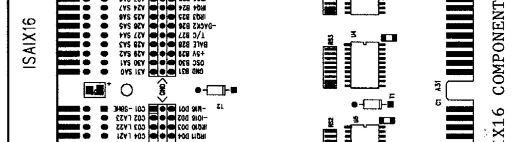


5
6 THEORY OF OPERATION The Bus Isolation Extender provides bus signals and power isolation between the system motherboard and the add-on board on the extender. The signals are isolated using state of art analog switches that allows bi-directional signal flow. When the analog switches are turned off, the bus signals at the extender side are isolated from the system bus. When the analog switches are turned on, the bus signals are connected. The analog switch provides no signal "buffering". That means, the bus signals are not reconditioned at TTL levels, nor are they redriven by any active amplifier. Any AC/DC signal loading on the add-on board will have a direct effect on the signal lines on the system motherboard. The analog switch introduces only less than 250 picoseconds delay to the signals. Such minimal delay makes the analog switch suitable for very fast bus operation. The power isolation is implemented using MOSFETs. The MOSFETs are biased to allow slow ramping up of current through the Bus Isolation Extender to the add-on boards without causing a power surge or glitch to the system power. When the voltage on the +5V line on the add-on board reaches above 4.5 volts, the logic on the extender will turn on the analog switches to connect the bus signals. When the Bus Isolation Extender is switched off, the logic on the extender board will disconnect the bus signals immediately, and shut down the power slowly. In addition, a 16ms reset pulse is generated to the add-on board on top of the extender, whenever the extender is switched on. If the system issues a reset pulse while the bus is connected, the extender will pass that reset pulse to the add-on board without disconnection or reconnection. An on-board red status LED will blink about twice a second, when the power and the signals are completely connected between the add-on board and the system bus. The red LED will stay off, if the Bus Isolation Extender is turned off or if the +5 and +12 volts do not reach operating voltages within 16ms after power up. During operation, if a short circuit condition is developed between +5 and +12V to ground, the logic will shut off the power and the red LED. The speaker will buzz in a continuous tone to alert the operator. User needs to switch the extender off, to reset the short circuit logic. The add-on boards should be inserted or removed from the extender only when the extender is switched off and the red LED is not blinking and the speaker is not buzzing. Serious damages to the system, extender and the add-on board could happen if the add-on board is inserted or removed when the bus is still connected. LOCAL and EXTERNAL CONTROL The Bus Isolation Extender has an unique external control feature. This feature is very useful in production environment and it can be easily implemented in many ways. It allows external toggle switch or TTL logic inputs to control the operation of the extender. When used with proper software, this feature helps to automate the test process without requiring manual switching by the operator. This external control feature is accessible through the W7 header located by the on-board toggle switch. The header is keyed for ribbon type of connector interface. The 2X5 header has the pins defined as on page 7 under W7 Pin headers. ON-BOARD TOGGLE SWITCH OPERATION This is the default operation mode as configured by the factory. This configuration allows single toggle switch operation without any external connection. A jumper is installed between pin 1 and pin 3 of the W7 header. It requires an operator to manually toggle the switch up for bus connection and toggle it down for bus isolation. When the switch is toggled up, both the power and the signals are connected by the on-board logic
7 EXTERNAL TOGGLE SWITCH OPERATION An external toggle switch can be connected between pin 5 and pin 6 of the W7 header to simulate the on-board toggle switch. In this configuration, the on-board toggle switch should be turned off (down position), and the jumper remains in pin 1 and pin 3 of W7 header. The external switch can be mounted anywhere outside the chassis for easier access. An external LED can also be connected through pin 9 and pin 10 of the W7 header, so it can provide a status outside the chassis. A blinking LED is recommended instead of regular LED. The on-board LED and the toggle switch do not need to be removed in this mode of operation. EXTERNAL LOGIC CONTROL OPERATION The Bus Isolation Extender can also be controlled by external TTL compatible signals. If the jumper remains on pin 1 and pin 3 of W7 header, a single TTL low control line connecting to pin 5 or a TTL high signal to pin 8 of W7 header can control both the power and signal isolation and connection as the toggle switch. If the jumper on pin 1 and pin 3 of W7 header is removed, then two TTL control lines can be used to control the bus signals and the power separately. The TTL control line connects to pin 5 or pin 8 will control the power and the TTL control line that connects to pin 3 will control the signal. The TTL control lines can come from any digital output source, such as the output pins of the parallel printer port in the CPU system. If the external TTL control lines are from sources outside the same CPU system, the ground pins on pin 6 or pin 7 of the W7 header should be connected to the signal ground of the external sources. The power should be connected first, then followed by the bus signals. Notice that pin 5 allows a TTL low signal to power up the extender, while pin 8 allows a TTL high signal to power up the extender. For system that requires the extender to be powered up from cold start, user can choose from available sources of either initial high or initial low signal to bring the extender up. VOLTAGE MARGIN, CURRENT MEASUREMENT AND EXTERNAL POWER SOURCE The ISAIX16 Bus Isolation Extender is provided with pluggable slow blow fuses. One 4 amp fuses is used for the +5V and three 1.6 amp fuses are used for the -5V, +12V, and -12V. User can perform voltage margin and current measurement with or without the fuses. Without using the fuse, external power can be connected to pin 2 or pin 3 of the fuse sockets to provide voltage margin test to the add-on boards on the extender. By moving the fuse to pin 2 and pin 4 location, user can provide power to pin 4 and still protected by the fuse. The pin 1 of these jumpers are tie directly to the system power and they should not be connected to external sources. When external power are applied through the fuse sockets, the current are still controlled by the MOSFETs, which regulates the ramping of the voltages. A minimum of +4.5V on the +5V power line is required to maintain the operation. Otherwise the logic on the extender will shut down the analog switches and isolate the bus signals. A short circuit sensing logic is also built in to protect the system. The short circuit logic will sense shorts on +5V and +12V and automatically shut off all power. The shorts can be either introduced accidentally during test or may already exist on the board under test. In short circuit condition, the speaker will generate a continuous tone to alert the user. In normal condition, the speaker will buzz once a second to alert the user that the Bus Isolation Extender is powered up. An ampere meter can be connected between the fuse socket pins with or without the fuse to measure the current consumed by the add-on board on top of the extender. The leads of the ampere meter should be as short as possible, to avoid excessive voltage drop below 4.5V. User may change the fuses to other type, as long as the 5V will not drop below 4.5V when the add-on board draws maximum current
8 TROUBLESHOOTING AND SELF SERVICE It is possible the Bus Isolation Extender could be damaged during operation. Our experience has shown, two of the most common problems associated with the Bus Isolation Extenders are blown fuses and blown buffer ICs. Such failures are usually caused by: 1. Users accidentally pull the add-on board while the bus is still connected. This happens especially when the user is not yet used to the procedure, and occasionally forget to switch the extender off while removing the add-on board. One must observe the red LED to make sure it is not blinking or listen to the speaker before adding or removing the add-on board. This action will cause the fuses and the buffer ICs to blow; especially, the one have signals next to the power pins. Because the add-on board could be removed at an angle, which shorted the power pins to the signal pins nearby. 2. The extender is lifted or wiggled side to side while add-on board is being removed or added. This happens if the extender is not tied down firmly. It is very important for user to find an appropriate way to hold down the extenders using brackets or fixtures in open or closed chassis environment, to prevent this to happen. Since the Bus Isolation Extender is still connected to the system bus, this will cause sparking in both power and signal pins that will most likely damage the buffer ICs. 3. Shorted power to signal pins or signal to signal pins on the add-on board. This condition will usually cause an overload to the buffer IC and damage it. Do not test the failed addon board on the Bus Isolation Extender again until the cause is corrected. 4. Extender connector pins are damaged due to wearout or rough handling. We strongly recommend the use of Bus Wearout Extenders, especially in production environment We would recommend the following steps for user self troubleshooting and field testing before returning the extender for factory service. 1. Check the extender connector pins for any physical damage, and correct them if possible. 2. Check the fuses for continuity and replaced them if not. 3. Check for all power to ground short. There are over-voltage protection components on-board that will short to ground when fired in severe sparking conditions. Locate and replace the components. 4. Visually inspect the buffer ICs for physical cracks, burn marks, etc. When the buffer IC is damaged, it will usually smoke while the bus is being connected. The damage could be caused by sparking or ESD from previous operation. Replace the damaged buffer ICs and try again. 5. Check buffer ICs by looking at the buffer pins with or without the add-on board and turn on the extender. The IC has pin 1 and 10 grounded, pin 20 connected to VCC and pin 19 as control (low for connect). Pin 2-9 and pin are the corresponding buffer pins. Test the pins using a logic probe. The probe should indicate the same condition; H, L or blinking on both pins of the buffer pair. Replace the buffer IC, if the condition is not the same. Our experience shows the buffers ICs at four corners are most likely to be damaged in the operation. Adex Electronics will assist customers over the phone to locate the damaged components and recommend further actions. Adex Electronics can also provide the components as spare parts to the customers. Each bus isolation extender is provided with a bag of spare parts, with 2 fuses of each type and 2 buffer ICs. -15-
9 BOARD INITIALIZATION Bus Isolation Extender isolates power and bus signals between the add-on board and the motherboard. Each time the toggle switch is turned off, the power to the add-on board is lost. Therefore, the information in the registers and memory on the add-on board will also be lost. For the next add-on boards to be tested again, the add-on board will need to be reinitialized, after the powers are reconnected. User will need to develop an initialization routine to restore the information back to the add-on board, before running the test. It can be done in a batch file where the initialization routine is placed before the test routine. The initialization routine can search for a previous saved configuration file and use it to reinitialize the add-on board. The test software should display the test results and messages to tell the operator when to remove and add another board for test, and how to restart the test. Every time the Bus Isolation Extender is power up or down, the on-board logic will resynchronize itself to disconnect or reconnect properly. A reset signal will also be generated to the add-on board under test during reconnection. In automated system, the initialization software should allow approximately 20 ms delay after the extender is turned on, before attempt to reinitialized the board. In manual toggle switch operation, the user should wait until the red LED is blinking before reinitialization. In software control operation, the LED- signal could be sensed externally at logic low state at least twice contiguously by the software to confirm the bus is reconnected, before reinitialization. During disconnect, the user should wait for the red LED to stop blinking before removing the add-on board under test. In software control operation, the LED- should be sensed high at least twice contiguously before putting out messages to remove the board. MOUNTING OF BUS ISOLATION EXTENDER The Bus Isolation Extender incorporates very fast CMOS buffers for isolation of bus signals between the add-on board and the motherboard. These CMOS buffers are extremely sensitive to voltage spikes and can be easily damaged by Electrostatic Discharge (ESD) or any sparking due to intermittent contacts. It is necessary for users in production environment to mount the Bus Isolation Extender firmly against a common platform where the motherboard is mounted. For in chassis testing, a fixture or a bracket should be developed to hold the Bus Isolation Extender to the chassis. For out of chassis environment, user should tie the motherboard and the Bus Isolation Extender down against a common platform. Whatever the fixture or bracket design is used, one should not allow the Bus Isolation Extender to be lifted with the add-on board nor to wiggle side to side. An inexpensive and simple bracket has been designed by Adex Electronics for in chassis use and they can be ordered with part number ISABK1. The bracket design, however is free to user as reference
10 - Blank - Appendix
11 USING PARALLEL PORT as EXTERNAL TTL CONTROL The following information on the PC/AT parallel ports is provided for users, who wish to use the parallel port pins as the TTL control lines to the Bus Isolation Extenders. 1st Parallel Port: Data Register = 378; Status Register = 379; Control Register = 37A; IRQ = 7 2nd Parallel Port: Data Register = 278; Status Register = 279; Control Register = 27A; IRQ = 5 Data Register: Bit 0-7 = Data Bit 0-7 Status Register: Control Register: Bit 7 = /BUSY Bit 7 = N/A Bit 6 = /ACK Bit 6 = N/A Bit 5 = PE Bit 5 = N/A Bit 4 = SLCT Bit 4 = IRQ_ENABLE Bit 3 = /ERROR Bit 3 = SLCT_IN Bit 2 = N/A Bit 2 = /INIT Bit 1 = N/A Bit 1 = AUTO_FEED Bit 0 = N/A Bit 0 = STROBE The female 25 pin parallel port pin outs are: 1 /STROBE (output) 14 /AUTO_FEED (output) 2 Data 0 (I/O) 15 /ERROR (Input) 3 Data 1 (I/O) 16 /INIT (output) 4 Data 2 (I/O) 17 /SLCT_IN (output) 5 Data 3 (I/O) 18 Gnd 6 Data 4 (I/O) 19 Gnd 7 Data 5 (I/O) 20 Gnd 8 Data 6 (I/O) 21 Gnd 9 Data 7 (I/O) 22 Gnd 10 /ACK (Input) 23 Gnd 11 BUSY (Input) 24 Gnd 12 PE (Input) 25 Gnd 13 SLCT (Input) Note: 1. /STROBE, BUSY, /AUTO_FEED, /SLCT_IN are inverted by Hardware (1 in software will appear as low at pin). 2. During power up, parallel port pins /STROBE, /AUTO_FEED, /SLCT_IN are reset to logic high; and /INIT is reset to logic low. After BIOS initialization, /INIT is toggled to high and /SLCT_IN is toggled to low. 3. Depending on the sequence of the BIOS initialization in each CPU system, one can use any of the signal pins, low or high to bring the extender up during cold boot. In some systems, an extra soft reboot by Ctrl Alt Del, after the first power up, may be necessary to get the plug and play boards to be recognized by BIOS. 4. The LED- pin on the W7 header on the Bus Isolation Extender could be connected to the SLCT pin on the parallel port (pin 13) as status input. The LED- at low will indicate successful bus connection and at high indicates no signal connection. The #Power_Control at pin 1 of the W7 header can also be used as a positive indication of cable connection and power connection. It could be connected to BUSY pin of the printer port for that purpose. 5. Some CPU system may relocate the parallel port I/O addresses or may use 3BC-3BF as the 1st parallel port /O addresses. One may verify the I/O addresses by looking at memory location 0:408, ROM BIOS data areas using the DOS debug command
12 ISA BUS PINOUT SOLDER SIDE B PIN NO. COMPONENT SIDE A GND 01 -CHCK RESET 02 SD7 +5V 03 SD6 IRQ9 04 SD5-5V 05 SD4 DRQ2 06 SD3-12V 07 SD2-0WS 08 SD1 +12V 09 SD0 GND 10 CHRDY -SMEMW 11 AEN -SMEMR 12 SA19 -IOW 13 SA18 -IOR 14 SA17 -DACK3 15 SA16 DRQ3 16 SA15 -DACK1 17 SA14 DRQ1 18 SA13 -REFRESH 19 SA12 BCLK 20 SA11 IRQ7 21 SA10 IRQ6 22 SA09 IRQ5 23 SA08 IRQ4 24 SA07 IRQ3 25 SA06 -DACK2 26 SA05 T/C 27 SA04 BALE 28 SA03 +5V 29 SA02 OSC 30 SA01 GND 31 SA00 ISA BUS PINOUT SOLDER SIDE D PIN NO. COMPONENT SIDE C -M SBHE -IO16 02 L23 IRQ10 03 LA22 IRQ11 04 LA21 IRQ12 05 LA20 IRQ15 06 LA19 IRQ14 07 LA18 -DACK0 08 LA17 DRQ0 09 -MEMR -DACK5 10 -MEMW DRQ5 11 SD8 -DACK6 12 SD9 DRQ6 13 SD10 -DACK7 14 SD11 DRQ7 15 SD12 +5V 16 SD13 -MASTER 17 SD14 GND 18 SD
13 WARRANTY Adex Electronics warrants this product against defects in material and workmanship for a period of one year from the date of purchase. During the warranty period, Adex Electronics will repair or replace this product at no charge. This warranty does not apply if the product has been damaged by accident, abuse, misuse or misapplication, nor as a result of service or modification made by others. Adex Electronics is not responsible for incidental or consequential damages resulting from use of this product. This includes damages to property and personal injury. The information in this manual has been carefully checked and is believed to be accurate. However, if there are any inaccuracies in this manual, Adex Electronics assumes no responsibility for any damages resulting from any omission or defects in this manual. Caution! Handle and store this product in an electrostatic safe environment. ESD could damage this product. Adex Electronics reserves the right to make changes in future product design without reservation and without notification to its users. For technical assistance contact: Adex Electronics Tel: Vista Terrace Fax: Lake Forest, CA adex@adexelec.com USA Website:
Active Extenders MODELS PC/AT150 & PC/AT200. Hot Swap PC/AT Bus Extender Boards. User Manual. Revision 8.1. March 30, 1999.
 Active Extenders MODELS PC/AT150 & PC/AT200 Hot Swap PC/AT Bus Extender Boards User Manual Revision 8.1 March 30, 1999 Catalyst Enterprises, Inc. 1439 Torrington Court San Jose, CA 95120 (408) 268-4145
APWR104HR Filtered Avionics Power Supply Module User s Manual
 HR Filtered Avionics Power Supply Module User s Manual BDM-610020010 Rev B ISO9001 and AS9100 Certified Filtered Avionics Power Supply Module User s Manual 103 Innovation Blvd. State College, PA 16804-0906
CMT6118 IDE Controller and Compact Flash Carrier with Floppy utilitymodule User s Manual
 CMT6118 IDE Controller and Compact Flash Carrier with Floppy utilitymodule User s Manual BDM-610020044 Rev. A CMT6118 ISOLATED IDE Controller and Compact Flash Carrier with Floppy utilitymodule User s
CMT36106/3106/56106/5106 Hard Drive Carrier utilitymodule. User s Manual. BDM Rev. E
 CMT36106/3106/56106/5106 Hard Drive Carrier utilitymodule User s Manual ISO9001 and AS9100 Certified BDM-610020031 Rev. E CMT36106/3106/56105/5106 Hard Drive Carrier utilitymodule User s Manual RTD Embedded
user manual Tri-M Engineering 1407 Kebet Way, Unit 100 Port Coquitlam, BC V3C 6L3
 WWW.TRI-M.COM GPS104 user manual Tri-M Engineering 1407 Kebet Way, Unit 100 Port Coquitlam, BC V3C 6L3 Web: www.tri-m.com email: info@tri-m.com Phone: 1.800. 665.5600 or 604.945.9565 COPYRIGHT BY TRI-M
IDE2CF User Manual IDE2CF
 The is a cost effective and easy to use adapter for connecting Compact Flash Cards (CF-Cards) to the standard IDE port of a single board computer (SBC) from MPL or other manufacturers. For mechanical fixing
APWR106HR Filtered Avionics Power Supply Module User s Manual
 HR Filtered Avionics Power Supply Module User s Manual BDM-610020071 Rev A Filtered Avionics Power Supply Module User s Manual 103 Innovation Blvd. State College, PA 16804-0906 USA Phone: (814) 234-8087
Octagon Systems Corporation, the Octagon logo, the Micro PC log and Micro PC are trademarks of Octagon Systems Corporation.
 5974 PC 104 Card COPYRIGHT Copyright 1993 Octagon Systems Corporation. All rights reserved. However, any part of this document may be reproduced provided that Octagon Systems Corporation is cited as the
PM-1037C V.1.0 CompactFlash Module
 PM-1037C V.1.0 CompactFlash Module Copyright Notice Copyright 2000. All Rights Reserved. Manual first edition JUL..01, 2000. The information in this document is subject to change without prior notice in
IDE2PCC User Manual IDE2PCC
 The is a cost effective and easy to use adapter for connecting PCMCIA PC Cards ATA with true IDE interface (PC Cards) to the standard IDE port of a single board computer (SBC) from MPL or other manufacturers.
PC/104+ to PCMCIA PC-Card/CardBus Adapter. Model 335 (Rev.A)
") SENSORAY CO., INC. PC/104+ to PCMCIA PC-Card/CardBus Adapter Model 335 (Rev.A) August 15, 2007 Sensoray 2007 7313 SW Tech Center Dr. Tigard, OR 97223 Phone 503.684.8005 Fax 503.684.8164 www.sensoray.com
SENSORAY CO., INC. PC/104+ to PCMCIA PC-Card/CardBus Adapter Model 335 (Rev.A) August 15, 2007 Sensoray 2007 7313 SW Tech Center Dr. Tigard, OR 97223 Phone 503.684.8005 Fax 503.684.8164 www.sensoray.com
CM102 IDE and Floppy Controller utilitymodule User s Manual
 CM102 IDE and Floppy Controller utilitymodule User s Manual BDM-610020012 Rev. A CM102 IDE and Floppy utilitymodule User s Manual RTD Embedded Technologies, INC. 103 Innovation Blvd. State College, PA
Setting new Standards. Active Extenders PCIAX CPCI64. Hot Swap PCI Bus Extender Boards PCI. User Manual Revision 5.
 Setting new Standards Active Extenders PCIAX CPCI64 Hot Swap PCI Bus Extender Boards PCI User Manual Revision 5.3 September, 2000 1439 Torrington Court San Jose, CA 95120 Tel: (408) 268-4145 Fax: (408)
CM6109 PCMCIA utilitymodule TM User s Manual
 CM6109 PCMCIA utilitymodule TM User s Manual BDM-610020003 Rev. B ISO9001 and AS9100 Certified CM6109 PCMCIA utilitymodule TM User s Manual RTD Embedded Technologies, INC. 103 Innovation Blvd. State College,
Advanced/ATX Jumpers and Connectors
 Advanced/ATX Jumpers and Connectors PLEASE NOTE: This motherboard product is no longer being manufactured by Intel. THESE DOCUMENTS ARE PROVIDED FOR HISTORICAL REFERENCE PURPOSES ONLY AND ARE SUBJECT TO
CM105 PCMCIA utilitymodule TM User s Manual
 CM105 PCMCIA utilitymodule TM User s Manual Publication No. CM105 9532 ,03257$17 127,&( SOFTWARE LICENSE AGREEMENT A) The enclosed disks contain intellectual property, i.e., software programs, that are
HE104 Version V11. High Efficiency Vehicle Power Supply. DC to DC Convertor. Technical Manual. Manufactured by. Tri-M Technology
 HE104 Version V11 High Efficiency Vehicle Power Supply DC to DC Convertor Technical Manual Manufactured by Tri-M Technology Rugged Power Solutions for Hostile Environments http://www.tri-m.com Revision:
IR104-V4. User Guide. Tri-M Technologies Inc. Opto-isolated Industrial I/O Relay Module
 IR104-V4 User Guide Opto-isolated Industrial I/O Relay Module Tri-M Technologies Inc. Toll Free: 1.800.665.5600 Direct: +1.604.945.9565 Email: info@tri-m.com Web: www.tri-m.com Preface Important Notes
CM17202 PC/104-Plus Fast Ethernet Controller utilitymodule. User s Manual. BDM Rev. A
 CM17202 PC/104-Plus Fast Ethernet Controller utilitymodule User s Manual BDM-610020025 Rev. A CM17202 PC/104-Plus Fast Ethernet Controller utilitymodule User s Manual RTD Embedded Technologies, INC. 103
EXM-12. Prototyping EXM Reference. RadiSys Corporation S.W. Koll Parkway. Beaverton OR (503) FAX: (503)
 FAX: (503)") EXM-12 Prototyping EXM Reference RadiSys Corporation 15025 S.W. Koll Parkway Beaverton OR 97006 (503) 646-1800 FAX: (503) 646-1850 07-0080-03 July 1993 EXM-12 Hardware Reference EPC and RadiSys are registered
EXM-12 Prototyping EXM Reference RadiSys Corporation 15025 S.W. Koll Parkway Beaverton OR 97006 (503) 646-1800 FAX: (503) 646-1850 07-0080-03 July 1993 EXM-12 Hardware Reference EPC and RadiSys are registered
SENSORAY CO., INC. PC/104+ CPU Board. Model 301 (Rev.B) September 23, 2004
 September 23, 2004") SENSORAY CO., INC. PC/104+ CPU Board Model 301 (Rev.B) September 23, 2004 Sensoray 2001 7313 SW Tech Center Dr. Tigard, OR 97223 Phone 503.684.8073 Fax 503.684.8164 www.sensoray.com 1 Table of Contents
SENSORAY CO., INC. PC/104+ CPU Board Model 301 (Rev.B) September 23, 2004 Sensoray 2001 7313 SW Tech Center Dr. Tigard, OR 97223 Phone 503.684.8073 Fax 503.684.8164 www.sensoray.com 1 Table of Contents
CM17215HR 100MB/s Fiber CM17212HR 10/100MB/s UTP PC/104-Plus Dual Ethernet utilitymodule. User s Manual. BDM Rev. A
 CM17215HR 100MB/s Fiber CM17212HR 10/100MB/s UTP PC/104-Plus Dual Ethernet utilitymodule User s Manual BDM-610020066 Rev. A CM17215HR 100MB/s Fiber CM17212HR 10/100MB/s Twisted Pair PC/104-Plus Dual Ethernet
SIPS - Group. Technical Description May ISA96 Bus Specification V 1.0
 SIPS - Group Technical Description May 1995 ISA96 Bus Specification V 1.0 o:\text\normen\isa96bu1.doc SIPS - Group Specification ISA96-Bus page 1 Contents 1. Notation...3 2. ISA96 Overview...4 2. 1 General...4
IP300 USER S MANUAL. 3.5-inch form factor ETX Base Board. Version 1.0A
 IP300 3.5-inch form factor ETX Base Board USER S MANUAL Version 1.0A Acknowledgments PS/2 are trademarks of International Business Machines Corporation. Microsoft Windows is a registered trademark of Microsoft
PLEASE NOTE: This product is no longer being manufactured by Intel. THIS DOCUMENT IS PROVIDED FOR HISTORICAL REFERENCE PURPOSES ONLY.
 Premiere/PCI II Jumpers & Connectors PLEASE NOTE: This product is no longer being manufactured by Intel. THIS DOCUMENT IS PROVIDED FOR HISTORICAL REFERENCE PURPOSES ONLY. Information in this document is
PMDX-105. I/O Option Riser Board User s Manual. Document Revision: 1.1 Date: 7 September 2004 PCB Revision: PCB-443A
 PMDX-105 I/O Option Riser Board User s Manual Date: 7 September 2004 PMDX Web: http://www.pmdx.com 7432 Alban Station Blvd., A105 Phone: +1 (703) 912-4991 Springfield, VA 22150-2321 USA FAX: +1 (703) 912-5849
VSX-6150 DM&P Vortex86SX 300MHz PC/104 CPU Module with 2S/2USB/GPIO 128MB DDR2 Onboard User s Manual (Revision 1.2A)
") VSX-6150 DM&P Vortex86SX 300MHz PC/104 CPU Module with 2S/2USB/GPIO 128MB DDR2 Onboard User s Manual (Revision 1.2A) Copyright The information in this manual is subject to change without notice for continuous
VSX-6150 DM&P Vortex86SX 300MHz PC/104 CPU Module with 2S/2USB/GPIO 128MB DDR2 Onboard User s Manual (Revision 1.2A) Copyright The information in this manual is subject to change without notice for continuous
OPERATIONS MANUAL PPM-USB2
 OPERATIONS MANUAL PPM-USB2 WinSystems reserves the right to make changes in the circuitry and specifications at any time without notice. Copyright 2004 by WinSystems. All Rights Reserved. REVISION HISTORY
PC/104 Plus CardBus Adapter Card PC/104 Plus CompactFlash Plus Adapter Card Reference Manual Models 2851 and 2852 Document #6555, rev.
 PC/104 Plus CardBus Adapter Card PC/104 Plus CompactFlash Plus Adapter Card Reference Manual Models 2851 and 2852 Document #6555, rev. B05 CONTACT INFORMATION Front Desk: 303 430 1500 Technical Support:
ICN Mini Link. User s Guide. 1731N Model A Mini Link Board for PC AT (Version 1) 1732N Model A ICN Interface Board (Version 1)
 1732N Model A ICN Interface Board (Version 1)") ICN Mini Link User s Guide 1731N Model A Mini Link Board for PC AT (Version 1) 1732N Model A ICN Interface Board (Version 1) MicroMod Automation, Inc. The Company MicroMod Automation is dedicated to improving
ICN Mini Link User s Guide 1731N Model A Mini Link Board for PC AT (Version 1) 1732N Model A ICN Interface Board (Version 1) MicroMod Automation, Inc. The Company MicroMod Automation is dedicated to improving
CM310/CM16310 Quad Serial Port utilitymodule. User s Manual
 CM310/CM16310 Quad Serial Port utilitymodule User s Manual BDM-610020016 Rev. C CM310/CM16310 Quad Serial utilitymodule 1 RTD Embedded CM310/CM16310 Quad Serial Port utilitymodule User s Manual RTD Embedded
SIPS - Group. Technical Description May AT96 Bus Specification V 1.1
 SIPS - Group Technical Description May 1995 AT96 Bus Specification V 1.1 o:\text\normen\at96bus1.doc Contents 1. Notation...3 2. AT96 Overview...4 2. 1 General...4 2. 2 Recommendations...4 3. Signal Description...5
Manual HE104. Tri-M Technologies Inc.
 Manual HE104 Tri-M Technologies Inc. Our company network supports you worldwide with offices in Germany, Austria, Switzerland, Great Britain and the USA. For more information please contact: FORTEC Elektronik
VK-3iX WARRANTY REGISTRATION FORM
 VK-3iX WARRANTY REGISTRATION FORM Unit Serial Number: Customer Name: Address: Date of Purchase: Purchased From: Dealer Name: Address: IMPORTANT NOTE: In order to receive the full five year product warranty,
CF15118 CompactFlash Carrier utilitymodules User s Manual
 CompactFlash Carrier utilitymodules User s Manual BDM-610020105 Rev. A CompactFlash Carrier utilitymodules User s Manual RTD Embedded Technologies, Inc. 103 Innovation Blvd. State College, PA 16803-0906
duagon D201 ISA to PC/104 adapter Data Sheet
 duagon This document describes the d0 ISAto- PC/0 bus adaoter. It is intended mainly for lab use. The widely spread PCs support a test and diagnostic platform for software development. Data Sheet D0 ISA
Sensoray Model 627 CompactPCI to PCI Adapter
 Sensoray Model 627 CompactPCI to PCI Adapter Revised December 19, 2003 TABLE OF CONTENTS LIMITED WARRANTY... 4 SPECIAL HANDLING INSTRUCTIONS... 4 1. INTRODUCTION... 5 2. SYSTEM REQUIREMENTS... 5 3. SPECIFICATIONS...
LPT-to-I2C SE. Hardware Reference Guide.
 LPT-to-I2C SE Hardware Reference Guide http://www.i2ctools.com/ November 1, 2008 Information provided in this document is solely for use with the LPT-to-I2C SE product from SB Solutions, Inc. SB Solutions,
TARA CONTROLS AGC-5. UCI Random Start USER S GUIDE. With Optional Warning Flashes for the Hearing Impaired. TARA CONTROLS by Cartessa Corporation
 TARA CONTROLS AGC-5 UCI Random Start USER S GUIDE With Optional Warning Flashes for the Hearing Impaired TARA CONTROLS by Cartessa Corporation 4825 Cincinnati-Brookville Road Shandon, Ohio 45063 Phone:
Torque Series LCD Remote Panel Installation/Operation Manual Model: TQ-DSP-12/24
 Torque Series LCD Remote Panel Installation/Operation Manual Model: TQ-DSP-12/24 Section Page Introduction 1 Materials Provided 1 I) Safety Instructions 1 A) Inverter Safety Instructions 1 B) Battery Safety
Resolver to Digital Expansion Board
 Resolver to Digital Expansion Board Catalog No. EXB009A01 Installation and Operating Manual 6/98 MN1313 Table of Contents Section 1 General Information............................. 1-1 Introduction....................................
PM-LX2 Quick Installation Guide Version 1.0
 PC/104 SBC with AMD Geode LX800 CPU, VGA/TTL, LAN, USB 2.0 and CF II Package List PM-LX2 Quick Installation Guide Version 1.0 Mar. 30, 2009 PM-LX2 package includes the following items: 1 x PM-LX2 Single
OPERATING PROCEDURES for the UPS-S2 Universal Power Supply Series 2
 OPERATING PROCEDURES for the Universal Power Supply Series 2 Vanguard Instruments Co., Inc. 1520 S. Hellman Ave. Ontario, California 91761 TEL: 909-923-9390 November 2013 FAX: 909-923-9391 REV. 2 SAFETY
Mercator II User Manual
 Mercator II User Manual PC/104-Plus I/O Module with 2 Dual 10/100 Ethernet Switches and DIO Revision Date Comment A 11/19/2012 Initial Release A.1 5/2/13 Minor update with enhanced Ethernet description
VSX-2812 PC/104 VGA/LCD/DVI
 VSX-2812 PC/104 VGA/LCD/DVI Module User s Manual (Revision 1.0A) Copyright The information in this manual is subject to change without notice for continuous improvement in the product. All rights are reserved.
BRG17088HR User's Manual PCI to ISA Bridge PC/104-Plus Module
 BRG17088HR User's Manual PCI to ISA Bridge PC/104-Plus Module ISO9001 and AS9100 Certified BDM-610020053 Rev D BRG17088HR User's Manual RTD EMBEDDED TECHNOLOGIES, INC. 103 Innovation Blvd State College,
GPS1000 A GPS RECEIVER FOR EDUCATIONAL, ENGINEERING, SCIENTIFIC and R&D PURPOSES COMPATIBLE WITH GPS OPENSOURCE CODE.
 GPS1000 DATA SHEET GPS1000 A GPS RECEIVER FOR EDUCATIONAL, ENGINEERING, SCIENTIFIC and R&D PURPOSES COMPATIBLE WITH GPS OPENSOURCE CODE. CONTENTS Page No. Introduction 1 Features 1 Section 1 GPSRF Board
EPSON. DYO 211 & 212 Dual Drive. User s Guide. Printed on recycled paper with at least 10% post-consumer content.
 EPSON DYO 211 & 212 Dual Drive User s Guide Printed on recycled paper with at least 10% post-consumer content. IMPORTANT NOTICE DISCLAIMER OF WARRANTY Epson America makes no representations or warranties,
INSTRUCTION MANUAL. Sensoray Model 720RB/DIN. Relay I/O Board (Rev A) October 12, 2001
 October 12, 2001") INSTRUCTION MANUAL Sensoray Model 720RB/DIN Relay I/O Board (Rev A) October 12, 2001 For Technical Support contact Sensoray Co., Inc. 7313 SW Tech Center Dr., Tigard, Oregon 97223, USA Tel:(503) 684-8005
INSTRUCTION MANUAL Sensoray Model 720RB/DIN Relay I/O Board (Rev A) October 12, 2001 For Technical Support contact Sensoray Co., Inc. 7313 SW Tech Center Dr., Tigard, Oregon 97223, USA Tel:(503) 684-8005
MOTOROLA SDI INTERFACE USER S MANUAL
 nc. SDIUM/D MAY 1996 MOTOROLA SDI INTERFACE USER S MANUAL 1996 MOTOROLA INC.; ALL RIGHTS RESERVED nc. Important Notice to Users While every effort has been made to ensure the accuracy of all information
WAFER-LX2-800 Quick Installation Guide Version 1.1
 3.5 SBC with AMD Geode LX800 onboard Processor, 8 COM, DDR 400MHz, VGA/LCD/LVDS display, 4 x USB2.0 WAFER-LX2-800 Quick Installation Guide Version 1.1 June. 02, 2008 Package Contents WAFER-LX2-800 package
Product Manual. 2 Port USB to RS-422 /485 Optical Isolated Adapter. Coolgear, Inc. Version 1.1 March 2018 Model Number: USB-2COMi-Si-M
 2 Port USB to RS-422 /485 Optical Isolated Adapter Product Manual Coolgear, Inc. Version 1.1 March 2018 Model Number: USB-2COMi-Si-M 2 USB-2COMi-Si-M Product Manual Revision History Revision Date Author
AHA PCI-to-Fast SCSI Host Adapter. Fast SCSI Connection for High-Performance SCSI Peripherals for Pentium PCs
 R AHA-2920 PCI-to-Fast SCSI Host Adapter Fast SCSI Connection for High-Performance SCSI Peripherals for Pentium PCs Introduction This installation guide provides the instructions needed to install and
STATUS Shiloh Road Alpharetta, Georgia (770) FAX (770) Toll Free
 FAX (770) Toll Free") Instruction Manual Model 1582-45L Data Switch September 2010, Rev A REMOTE LOCAL SWITCH STATUS SELECT REMOTE LOCAL LOCAL SELECT CHANNEL SELECT POWER MODEL 1582 SWITCH CROSS TECHNOLOGIES, INC. Data, drawings,
Instruction Manual Model 1582-45L Data Switch September 2010, Rev A REMOTE LOCAL SWITCH STATUS SELECT REMOTE LOCAL LOCAL SELECT CHANNEL SELECT POWER MODEL 1582 SWITCH CROSS TECHNOLOGIES, INC. Data, drawings,
G540 4-AXIS DRIVE REV 4: MAY 28, 2010
 Thank you for choosing to purchase the G540 4-Axis Drive System. If you are dissatisfied with it for any reason at all within two weeks of its purchase date, you may return it for a full refund provided
OPERATIONS MANUAL PPM-CARDBUS
 OPERATIONS MANUAL PPM-CARDBUS NOTE: This manual has been designed and created for use as part of WinSystems Technical Manuals CD and/or the WinSystems website. If this manual or any portion of the manual
R & D SPECIALTIES SERIES 100 RO CONTROLLER USERS MANUAL. 2004, by R & D Specialties, Inc. All Rights Reserved.
 R & D SPECIALTIES 2004, by R & D Specialties, Inc. All Rights Reserved. No part of this document may be copied or reproduced in any form or by any means without the prior written permission of R & D Specialties.
MODELS PCI-IDI-XX SERIES USER MANUAL
 10623 Roselle Street, San Diego, CA 92121 (858) 550-9559 FAX (858) 550-7322 contactus@accesio.com www.accesio.com MODELS PCI-IDI-XX SERIES USER MANUAL File: mpci-idi-xx.b1l Notice The information in this
PRODUCT MANUAL. PCM-DC-AT500 +5V DC/DC PC/104 Power Supply. WinSystems. WinSystems, Inc. 715 Stadium Drive Arlington, TX 76011
 WinSystems PCM-DC-AT500 +5V DC/DC PC/104 Power Supply PRODUCT MANUAL WinSystems, Inc. 715 Stadium Drive Arlington, TX 76011 http://www.winsystems.com MANUAL REVISION HISTORY P/N G400-0379-000B (PCM-DC-AT500)
Atmos Engineering, Inc. External Specification PN PC104 Air Data Atmodule PN Revision 6.0
 A T M O S E N G I N E E R I N G I N C. Atmos Engineering, Inc External Specification PN 410042 PC104 Air Data Atmodule PN 840025 Revision 6.0 Atmos Engineering, Inc 443 Dearborn Park, Rd Pescadero, CA
DIC310 User Manual. Chapter 1 Short description. Inconsistencies
 DIC310 User Manual English version Ver. 09.03 Inconsistencies Incorrect placement of IRQ10, IRQ11, IRQ14, IRQ15 lines names next to SW2 microswitch (back side) on PCBs with DNB: 31011220. For correct setting
PMDX-103. Parallel Port Isolator Board. User s Manual. Document Revision: 1.2 Date: 20 February 2007 PCB Revision: PCB-447B
 PMDX-103 Parallel Port Isolator Board User s Manual Date: 20 February 2007 PMDX Web: http://www.pmdx.com 9704-D Gunston Cove Rd Phone: +1 (703) 372-2975 Lorton, VA 22079-2366 USA FAX: +1 (703) 372-2977
CM316 Dual Serial Port utilitymodule User s Manual
 CM316 Dual Serial Port utilitymodule User s Manual AS9100 and ISO 9001 Certified BDM-610020054 Rev. B CM316 Dual Serial Port utilitymodule User s Manual RTD Embedded Technologies, INC. 103 Innovation
PCM PC/ bit Digital I/O Module. User Manual
 PCM-3724 PC/104 48-bit Digital I/O Module User Manual Copyright This documentation and the software included with this product are copyrighted 2008 by Advantech Co., Ltd. All rights are reserved. Advantech
ADSP-218x Family EZ-ICE Hardware Installation Guide
 ADSP-218x Family EZ-ICE Hardware Installation Guide 2000 Analog Devices, Inc. ADSP-218x Family EZ-ICE Hardware Installation Guide a Notice Analog Devices, Inc. reserves the right to make changes to or
Sensoray Model 623 PC/104+ to PCI Adapter. Revised December 19, Sensoray Model 623 Instruction Manual 1
 Sensoray Model 623 PC/104+ to PCI Adapter Revised December 19, 2003 Sensoray Model 623 Instruction Manual 1 TABLE OF CONTENTS LIMITED WARRANTY... 3 SPECIAL HANDLING INSTRUCTIONS... 3 1. INTRODUCTION...
DK 4 Game Selector INSTALL GUIDE
 DK 4 Game Selector INSTALL GUIDE Each DK Selector includes the following items: 1. DK Selector PWB 2. 4 power cables 12, 14, 16 & 18 3. Ribbon daisy chain cable 4. Mounting feet and screws Some of the
PV3500. Fuel Site Controller. Service Manual OPW Fuel Management Systems Manual M Rev. 1
 PV3500 Fuel Site Controller Service Manual 2002 OPW Fuel Management Systems Manual M11-00.03 Rev. 1 OPW Fuel Management Systems - System and Replacement Parts Warranty Statement Effective September 1,
PCM-3110/3111 PC/104 PCMCIA module
 PCM-3110/3111 PC/104 PCMCIA module The PCM-3110 is a PCMCIA driver in the PC/104 form factor. The PCM-3111 is a second PCMCIA socket when used in conjunction with the PCM-3110. The PCM-3110 is always designated
1S/USB/LAN/GPIO 128MB DDR2
 VSX-6117-X-V2 DM&P Vortex86SX 300MHz Mity-Mite CPU Module with 1S/USB/LAN/GPIO 128MB DDR2 Onboard User s Manual (Revision 1.0A) Copyright The information in this manual is subject to change without notice
PS8 - II. Professional Power Sequencer. User s Manual
 PS8 - II Professional Power Sequencer User s Manual IMPORTANT SAFETY INSTRUCTIONS READ FIRST This symbol, whenever it appears, alerts you to the presence of uninsulated dangerous voltage inside the enclosure.
VEX-6253 DM&P Vortex86EX 400MHz PC/104 CPU Module with 1S/2USB/LAN/AD/16-bit x-isa 128MB DDR3 Onboard User s Manual (Revision 1.
 VEX-6253 DM&P Vortex86EX 400MHz PC/104 CPU Module with 1S/2USB/LAN/AD/16-bit x-isa 128MB DDR3 Onboard User s Manual (Revision 1.0A) Copyright The information in this manual is subject to change without
DCS-E 1kW Series, DLM-E 3kW & 4kW Power Supplies
 DCS-E 1kW Series, DLM-E 3kW & 4kW Power Supplies M51A Option: Isolated Analog Programming Manual Power Supplies Elgar Electronics Corporation 9250 Brown Deer Road San Diego, CA 92121-2294 1-800-73ELGAR
chipdisk/1000-ide KTD-S0050-C
 chipdisk/1000-ide KTD-S0050-C User Information Table of Contents» Table of Contents «1 User Information... 1 1.1 About This Document... 1 1.2 Copyright Notice... 1 1.3 Trademarks... 1 1.4 Standards...
Emerald-MM-8Plus. PC/104-Plus 8-Port Multi-Protocol Serial Port Module. User Manual v1.04
 Emerald-MM-8Plus PC/104-Plus 8-Port Multi-Protocol Serial Port Module User Manual v1.04 Copyright 2006 1255 Terra Bella Ave. Mountain View, CA 94043 Tel (650) 810-2500 Fax (650) 810-2525 www.diamondsystems.com
Model HM-535 Power Supply Installation and Service Instructions
 Model HM-535 Power Supply Installation and Service Instructions 430-535 0104 2004 Heritage MedCall, Inc SENTRY INSTALLATION & SERVICE INSTRUCTIONS POWER SUPPLY UNIT Model HM-535 IMPORTANT SAFETY INSTRUCTIONS
G540 MANUAL MULTIAXIS STEP MOTOR DRIVE
 G540 MANUAL MULTIAXIS STEP MOTOR DRIVE PRODUCT DIMENSIONS PHYSICAL AND ELECTRICAL RATINGS Minimum Maximum Units Supply Voltage 18 50 VDC Motor Current 0 3.5 A Power Dissipation 1 13 W Short Circuit Trip
G540 User Manual. Date Modified: March 5, 2012 Page 1 of 10
 G540 User Manual Date Modified: March 5, 2012 Page 1 of 10 DIMENSIONS PHYSICAL AND ELECTRICAL RATINGS Minimum Maximum Units Supply Voltage 18 50 VDC Motor Current 0 3.5 A Power Dissipation 1 13 W Short
Installation Instructions
 Installation Instructions This document provides information on: important pre-installation considerations power supply requirements initial handling installing the module short circuit protection using
AD-7830 Servo Amplifier
 Instruction Manual IM-0606 AD-7830 Servo Amplifier Table of Contents General Information... 2 Introduction... 2 Receiving/Inspection... 2 Storage... 2 Equipment Return... 2 Abbreviations Used in This Manual...
TVA2.1 2-Channel Digital Amplifier Installation Manual
 TVA2.1 2-Channel Digital Amplifier Installation Manual SAFETY INSTRUCTIONS WARNING: TO REDUCE THE RISK OF FIRE OR ELECTRIC SHOCK, DO NOT EXPOSE THIS APPLIANCE TO RAIN OR MOISTURE. CAUTION: TO REDUCE THE
CIO-DO48H, CIO-DO96H and CIO-DO192H. User s Guide
 CIO-DO48H, CIO-DO96H and CIO-DO192H User s Guide Revision 4A April, 2001 Trademark and Copyright Information Measurement Computing Corporation, InstaCal, Universal Library, and the Measurement Computing
VS. 4 Game Selector INSTALL GUIDE
 VS. 4 Game Selector INSTALL GUIDE Each DK Selector includes the following items: 1. VS. 4 Game Selector PWB 2. 4 power cables 12, 14, 16 & 18 3. Ribbon daisy chain cable 4. Mounting feet and screws Some
Chapter 1 Introduction
 Chapter 1 Introduction Welcome to the I-Bus family of system enclosures. In this manual you will find the information you need to setup and maintain your 4800 or 4800 industrial system. The 4800 system
VC-422C VTR CONTROL ROUTER
 VC-422C VTR CONTROL ROUTER version 1.0 Lance Design 27 Fairview Avenue Ridgefield, CT 06877 Tel: 203-894-8206 / Fax: 203-894-8207 www.lancedesign.com CONTENTS 1) General Information 2) Operation/Examples
MODEL USB-DA12-8E Eight Channel Digital to Analog Converter USER MANUAL
 10623 Roselle Street, San Diego, CA 92121 (858) 550-9559 FAX (858) 550-7322 contactus@accesio.com www.accesio.com MODEL USB-DA12-8E Eight Channel Digital to Analog Converter USER MANUAL FILE: MUSB-DA12-8E.B1h
PMDX Axis Breakout/Motherboard for Gecko Stepper Motor Drivers User s Manual
 PMDX-131 4-Axis Breakout/Motherboard for Gecko Stepper Motor Drivers User s Manual Date: 24 July 2007 PMDX Web: http://www.pmdx.com 9704-D Gunston Cove Rd Phone: +1 (703) 372-2975 Lorton, VA 22079-2366
PWRguard PLUS Spring City Drive Waukesha, WI
 PWRguard PLUS www.westmountainradio.com 1020 Spring City Drive Waukesha, WI 53186 262-522-6503 sales@westmountainradio.com 2016, All rights reserved. All trademarks are the property of their respective
Design of a Programmable Bus for Microprocessor-Based Systems
 Design of a Programmable Bus for Microprocessor-Based Systems Dr. Kasim M. Al-Aubidy, Muthana A.K. Attyah Faculty of Engineering, Philadelphia University, Sweileh P. O. Box 1101, Amman JORDAN, Tel: 962-2-6734444,
SATA34106 SATA Drive Carrier
 SATA34106 SATA Drive Carrier User s Manual BDM-610020085 Revision A www.rtd.com ISO9001 and AS9100 Certified Accessing the Analog World SATA Drive Carrier User s Manual RTD Document Number: BDM-610020085
PS/IO Circuit Board Retrofit
 S&C 6800 Series Automatic Switch Controls PS/IO Circuit Board Retrofit Table of Contents Section Page Introduction Qualified Persons.... 2 Read this Instruction Sheet.... 2 Retain this Instruction Sheet....
PMDX-108-Output. 8-Channel Isolated Output Board for PC parallel port pins 2-9. User s Manual
 PMDX-108-Output 8-Channel Isolated Output Board for PC parallel port pins 2-9 User s Manual Date: 25 February 2010 PMDX Web: http://www.pmdx.com 9704-D Gunston Cove Rd Phone: +1 (703) 372-2975 Lorton,
IDAN-RSATA-SYS104 SATA Drive Carrier
 IDAN-RSATA-SYS104 SATA Drive Carrier User s Manual BDM-610020081 Revision B www.rtd.com ISO9001 and AS9100 Certified Accessing the Analog World SATA Drive Carrier User s Manual RTD Document Number: BDM-610020081
PRODUCT MANUAL. PCM-MIO-G-AD-1 16 Channel, 16-bit Analog Inputs and 48 Digital I/O. WinSystems, Inc. 715 Stadium Drive Arlington, TX 76011
 PCM-MIO-G-AD-1 16 Channel, 16-bit Analog Inputs and 48 Digital I/O PRODUCT MANUAL WinSystems, Inc. 715 Stadium Drive Arlington, TX 76011 http://www.winsystems.com Telephone +1 817-274-7553 REVISION HISTORY
ISA Host Controller 15a Hardware Reference Release 1.2 (October 16, 2017)
") ISA Host Controller 15a Hardware Reference 1 ISA Host Controller 15a Hardware Reference Release 1.2 (October 16, 2017) Purpose: Host Controller to support the ISA bus according to the PC/104 specification.
ISA Host Controller 15a Hardware Reference 1 ISA Host Controller 15a Hardware Reference Release 1.2 (October 16, 2017) Purpose: Host Controller to support the ISA bus according to the PC/104 specification.
BUF(PCI)13. PCI Bus Expansion Adapter Set. User's Guide
13. PCI Bus Expansion Adapter Set. User's Guide") PCI Bus Expansion Adapter Set User's Guide Copyright Copyright 2000 CONTEC Co., LTD. ALL RIGHTS RESERVED No part of this document may be copied or reproduced in any form by any means without prior written
PCI Bus Expansion Adapter Set User's Guide Copyright Copyright 2000 CONTEC Co., LTD. ALL RIGHTS RESERVED No part of this document may be copied or reproduced in any form by any means without prior written
Installation Guide AHA-1540CP/1542CP. ISA-to-SCSI Plug and Play High-Performance Bus Master Host Adapter with SCSISelect Utility
 R Installation Guide AHA-1540CP/1542CP ISA-to-SCSI Plug and Play High-Performance Bus Master Host Adapter with SCSISelect Utility 1 Introduction This Installation Guide explains how to install and configure
Digital Lighting Systems, Inc. PD216. Two Channel Dimmer and Switch Packs PROTOCOL USER'S MANUAL. PD216-UM Rev. E - 02/03
 Digital Lighting Systems, Inc. PD26 Two Channel Dimmer and Switch Packs PROTOCOL PD26 S2 S USER'S MANUAL PD26-UM Rev. E - 02/03 Digital Lighting Systems PD26 User's Manual - Page GENERAL DESCRIPTION The
PCL channel Isolated Digital I/O Card
 PCL-730 32-channel Isolated Digital I/O Card Copyright This documentation is copyrighted 1996 by Advantech Co., Ltd. All rights are reserved. Advantech Co., Ltd. reserves the right to make improvements
MONITOR Shiloh Road Alpharetta, Georgia (770) FAX (770) Toll Free
 FAX (770) Toll Free") Instruction Manual Model 1584-25 Splitter December 2009 Rev B MITOR 1 MITOR 2 A B MODEL 1584 DIVIDER CROSS TECHNOLOGIES C. Data, drawings, and other material contained herein are proprietary to Cross Technologies,
Instruction Manual Model 1584-25 Splitter December 2009 Rev B MITOR 1 MITOR 2 A B MODEL 1584 DIVIDER CROSS TECHNOLOGIES C. Data, drawings, and other material contained herein are proprietary to Cross Technologies,