Diagnostics of Genie / Sauer Danfoss Joystick Controllers Deutsch type connection
|
|
|
- Dominick Owen
- 5 years ago
- Views:
Transcription


1 Diagnostics of Genie / Sauer Danfoss Joystick Controllers Deutsch type connection Tools needed: Multi-meter Small Screwdriver Harness Adaptor Jumper Wires w/clips Three 1.5 volt AA or AAA Batteries Appropriate three battery holder Miscellaneous electronic components Small Soldering Iron and Solder.
2 Tech Tips Safety Rules Danger Failure to obey the instructions and safety rules in the appropriate Operator's Manual and Service Manual for your machine will result in death or serious injury. Many of the hazards identified in the operator s manual are also safety hazards when maintenance and repair procedures are performed. Do Not Perform Maintenance Unless: You are trained and qualified to perform maintenance on this machine. You read, understand and obey: o manufacturer s instructions and safety rules o employer s safety rules and worksite regulations o applicable governmental regulations You have the appropriate tools, lifting equipment and a suitable workshop. The information contained in this tech tip is a supplement to the service manual. Consult the appropriate service manual of your machine for safety rules and hazards.


3 Introduction From Left to Right: Dual-Axis with Proportional Rocker Controller used on Z135 Units Dual-Axis Proportional Controller used on ALC 500 and ALC 1000 Units Single-Axis Proportional Controller used on ALC 500 and ALC 1000 Units. The focus of this Tech Tip is to obtain a rapid diagnosis for a proportional controller installed on a Genie Aerial product utilizing the ALC500 and ALC1000 Sauer Danfoss Control Systems. The intent is to display the analog outputs of the controller so the unknown condition of a controller can be determined before installation or for verification of a faulty controller fault code from the ALC500 or ALC1000 diagnostic system.

4 Familiarization Start with familiarization of the controller layout and pin locations. This is a photo of the JS1000 controller socket. Notice the male pins. Note that Pin 1 is at the top right and also note the clockwise arrangement of the remainder of the pins. Analog connections: Pin 1 is GROUND IN Pin 2 is 5 volts DC Power IN Pin 3 is X OUT Pin 4 is Y OUT Pin 5 is Proportional Rocker OUT if equipped Pin 6 is Ground Return


5 The Deutsch Connector that is inserted into the socket of the JS1000 Controller Again note the pin numbers. Genie Part # This is an adaptor used to bridge this version of controllers to earlier models that used the AMP Spade type joysticks that did not have the Deutsch connector. It will be used in this Tech Tip as an interface for use with a Voltmeter and as a connection for a diagnostic tool that will be explained in detail later.


6 Removing the connector end from harness Remove the flat spade-like connector by gently pressing the retaining tab of each pin with a small slotted head screwdriver while pulling on the wire of that pin. This part can be reproduced with parts from a used harness or individual wires with female pins to install on the pins in the socket of the JS1000 Controller. This is the portion of the harness that will be used to diagnose the controller.
7 Adaptor Harness Available from Genie Parts Department For diagnostic purposes, this part can be reproduced with parts from a used harness or individual wires with female pins to install on the pins in the socket of the JS1000 Controller. Individual Wires with Female Terminal Ends Installed. Be sure that bare exposed terminal ends do not contact each other and that they have a firm snug fit to prevent coming loose and shorting.

8 Power Source: A three AA or AAA battery holder and three batteries will be used to power the controller for testing. The holder is available at any electronics or hobby store at an inexpensive cost. The input voltage for the controller must not exceed 5 volts DC. The three batteries will deliver approximately 4.8 volts when they are at full charge. We will use the value of 4.5 volts to represent used but serviceable batteries. If the voltage of the applied power supply is higher than 4.5 volts, the results will be a bit higher. Likewise, if the supply voltage is lower than 4.5 volts, the results will be a bit lower. For testing purposes, voltage needed for testing will need to fall in the range of 3.8 volts to 5 volts DC. Always verify voltage of the power supply before any diagnostic testing. If a wall wart type (AC to DC converter) power supply is used, be sure the output is regulated. Plug the wall wart in and check the output with a voltmeter. If the output is more than 5.0 volts, do not use it for testing these controllers.

9 Controller: STEP 1: (also: Steps 1 and 8 for ) Power Supply Voltage Measurement: The voltmeter representation is showing in this case a 4.5 volt DC power source available. It is important to verify enough voltage is available when conducting diagnostics. Do not exceed 5.0 volts. This photo shows Pins 1 and 2 connected to Battery Minus and Battery Plus respectively. No other leads are connected. The controller in the photo is Part Number It is a Single Axis Joystick that is used on Genie Models: After Serial Number: Z , Z51 383, Z , Z , Z135, S40/ , S60/65/HC 14782, S80/ S100/ , S120/
10 Step 2: (also: Steps 2 and 9 for ) Center Position Voltage Measurement: On the Single Axis controllers (101175), only the number 1, 2 and 4 terminals are used. 1 is the Ground Input 2 is the Power Plus Input (3.8 volts to 5 volts) 4 is the Output for the Y axis. When Pin 4 is connected to the voltmeter, the reading should be approximately half that of the voltage applied to pin 2. In this case the reading will be approximately 2.25 volts. If the power supply is 5.0 volts, the reading here will be approximately 2.5 volts. If 4.0 volts is the input at pin 2, the output here would be approximately 2.0 volts. This same relationship holds true for the remainder of testing. (Step 9) Pin 3 is for the X-Axis on The Positive lead from the voltmeter will be on Pin 3 for step 9. Pin 4 will not be connected for X-Axis test.
11 Step 3: (also: Steps 3 and 10 for ) High-Side Voltage Measurement: Positioning the Socket or TAB at 12:00 O clock will make it easier to reference directions later. Reference will be from the bottom as in this photo. Moving The Joystick Handle Towards the TAB (12:00 O clock) located on the controller housing we will see the voltage increase to approximately 0.40 to 0.50 volts less than the Power Supply voltage (4.5 volts) at full deflection of the joystick handle. In this case about 4.10 volts. Again, a 5.0 volt supply would be about 4.6 volts and a 4.0 volt supply will be about 3.6 volts. The increasing voltage as the handle is moved should be a smooth and linear proportional voltage increase. If the voltage change is erratic, choppy or interrupted, the signal to the control circuit (ALC500 or ALC1000) will reflect the same and the control board will be confused and go into a fault mode. (Step 10) Controller: Facing the controller from the bottom, move the Joystick Handle to the 9:00 o clock position (High-Side). Reading will be approximately the same as Step 3. The Positive lead from the voltmeter will be on Pin 3 for step 10. Pin 4 will not be connected for X-Axis test.
 at full deflection of the joystick handle. This will be a voltage reading of from 0.40 to 0.50 volts throughout the accepted input range of 3.")
12 Step 4: (also: Steps 4 and 11 for ) Low-Side Voltage Measurement: Moving The Joystick Handle Away (6:00 O clock) from the TAB located on the controller housing we will see the voltage decrease to approximately 0.40 to 0.50 volts Above the Minus Supply (0.00 volts) at full deflection of the joystick handle. This will be a voltage reading of from 0.40 to 0.50 volts throughout the accepted input range of 3.8 to 5.0 volts at pins 1 and 2. The decreasing voltage as the handle is moved should be a smooth and linear proportional voltage decrease. If the voltage change is erratic, choppy or interrupted, the signal to the control circuit (ALC500 or ALC1000) will reflect the same and the control board will be confused and go into a fault mode. (Step 11) Controller: Facing the controller from the bottom, move the Joystick Handle to the 3:00 o clock position (Low-Side). Reading will be approximately the same as Step 4. The Positive lead from the voltmeter will be on Pin 3 for step 11. Pin 4 will not be connected for X-Axis test.
13 Step 5: (also: Steps 5 and 12 for ) Static State Current Measurement: Set the Multimeter to read MilliAmp DC Current. The Meter connections are as follows: Positive Lead of Current Meter connected to Battery Positive Negative Lead of Current Meter connected to Joystick Pin # 2 Negative Lead from Battery Pack connected to Joystick Pin # 1. This puts the current meter in series with the power supply and the Joystick controller. No other pins of the joystick will be connected. The current in the Hall Effect Circuits will be displayed. On the Single-Axis controller the current will be approximately 4.50 milliamps. For reference here, the current values at this static state are different for each of the three different controllers outlined in this Tech Tip : Single-Axis will be approximately 4.50ma : Dual-Axis will be approximately 8.50ma : Dual Axis w/ Proportional Rocker will be approximately 15.50ma (Steps 5 and 12 of will be approximately 8.50 milliamps)


14 Pictorial of Current Measurement Circuit: = 4.50ma = 8.50ma = 15.50ma Simple Voltage Circuit Diagram:

15 Step 6: (also: Step 13 for ) Resistance Measurement for Ground Return Circuit: No power applied. The Resistance between pin 1 and pin 6 for the Ground Return will not be continuity. It will be approximately 99,000Ωs to 101,000Ωs for the Sauer Danfoss Controllers included in this Tech Tip. It must not have a shorted or open reading. (Step 13 is identical to Step 6) End Diagnostic

16 Controller: Used on Genie Models AFTER Serial Numbers: Z , Z51 383, Z , Z , Z135, S40/ , S60/65/HC 14782, S80/ , S100/ , S120/ Step 7: This diagnostic is for Controller Part Number Dual-Axis Proportional Controller Return now to steps 1 thru 6 for the Y-Axis of the controller using PIN #4 as in steps 1 thru 6. Steps 8 thru 13 are for the X-Axis measurements of Controller Use Pin 3 for testing X-Axis of Diagnosis of X-Axis is similar to that of the Y-Axis except using PIN # 3 of the Deutsch Connector. Perform Steps 8 thru 13 using Pin 3 instead of PIN 4. Results will be similar to the Y-Axis testing.

17 Static State Current Measurement for : Set the Multimeter to read MilliAmp DC Current. The Meter connections are as follows: Positive Lead of Current Meter connected to Battery Positive Negative Lead of Current Meter connected to Joystick Pin # 2 Negative Lead from Battery Pack connected to Joystick Pin # 1. This puts the current meter in series with the power supply and the Joystick controller. No other pins of the joystick will be connected. The current in the Hall Effect Circuits will be displayed. On the Dual-Axis controller the current will be approximately 8.50 milliamps. For reference here, the current values at this static state are different for each of the three different controllers outlined in this Tech Tip : Single-Axis will be approximately 4.50ma : Dual-Axis will be approximately 8.50ma : Dual Axis w/ Proportional Rocker will be approximately 15.50ma

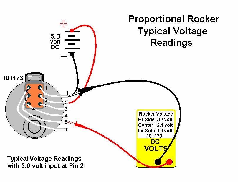
18 When a 5.0 volt potential is applied across inputs Pin 1 and Pin 2: This illustration points out the expected approximate results. Looking at the controller from the bottom side, moving the joystick handle towards the 12:00 o clock position will result with increasing voltage. This is the Y-Axis High Side. Pin 4 is used. Moving the joystick handle down towards the 6:00 o clock position will result with decreasing voltage. This is the Y-Axis Low-Side. Pin 4 is used. Likewise: Moving the joystick handle towards the 9:00 o clock position will result with increasing voltage. This is the X-Axis High Side. Pin 3 is used. Moving the joystick handle towards the 3:00 o clock position will result with decreasing voltage. This is the X-Axis Low-Side. Pin 3 is used. End Diagnostic


19 Controller: Dual-Axis with Proportional Thumb Rocker. Used on Z135 for: Primary Up/Down-Turntable Rotate-Primary Extend/Retract And: Jib Boom Up/Down-Platform Rotate-Jib Extend/Retract IMPORTANT INFORMATION: The Controller is different than the and in that It incorporates a Proportional Thumb Rocker located on the handle.

20 Testing the Y-Axis and X-Axis of the Controller will be performed using the same procedure used when testing the Controller. Refer to Steps 1 through 13 for these tests.
21

22 Static State Current Measurement for : Set the Multimeter to read MilliAmp DC Current. The Meter connections are as follows: Positive Lead of Current Meter connected to Battery Positive Negative Lead of Current Meter connected to Joystick Pin # 2 Negative Lead from Battery Pack connected to Joystick Pin # 1. This puts the current meter in series with the power supply and the Joystick controller. No other pins of the joystick will be connected. The current in the Hall Effect Circuits will be displayed. On the Dual-Axis with Proportional Rocker controller the current will be approximately milliamps. For reference here, the current values at this static state are different for each of the three different controllers outlined in this Tech Tip : Single-Axis will be approximately 4.50ma : Dual-Axis will be approximately 8.50ma : Dual Axis w/ Proportional Rocker will be approximately 15.50ma End Diagnostic
 controllers on the left are turned 90 degrees Counter-Clockwise with relationship to the other two Controllers (101175 and 101174).")
23 Diagnostic Tool Project Note the orientation of the controllers in the Z135 Platform Control Box. The two (Dual-Axis with Proportional Rocker) controllers on the left are turned 90 degrees Counter-Clockwise with relationship to the other two Controllers ( and ). This is to facilitate the orientation of the Proportional Rocker on the Joystick to reflect the actual movements of the functions they control. Primary Boom Extend-Retract and Jib Boom Extend-Retract. The Diagnostic Tool we will be assembling will replicate the characteristics of the as it is used in the Z135. The Diagnostic Tool can, however, be used on all the controllers covered in this Tech Tip.


24 Components Needed to Assemble Diagnostic Tool: These Parts are readily available at electronics stores. Three AA or AAA Batteries and a Battery Holder Six Light Emitting Diodes Must be 4.7 to 5.0 volts Max Forward Voltage. Single Pole-Single Throw Toggle Switch Component PC Board 750 Solder-Ringed Holes size will suffice Available from Genie Parts Department Adaptor Harness A small Soldering Iron will be needed to assemble the Diagnostic Tool.

25 Adaptor Harness Available from Genie Parts Department For diagnostic purposes, this part can be reproduced with parts from a used harness or individual wires with female pins to install on the pins in the socket of the JS1000 Controller. Individual Wires with Female Terminal Ends Installed.
26 Step A: Checking the LEDs: Check the LEDs before soldering onto circuit board This is correct and should light. This is incorrect and will NOT light. Remember that the LEDs need to be 4.7 to 5.0 volts Max Forward Voltage. They will burn out immediately if a lesser value is used.

27 Schematic and Wiring Diagram for Diagnostic Tool Remember that the LEDs need to be 4.7 to 5.0 volts Max Forward Voltage. They will burn out immediately if a lesser value is used.

28 Schematic and Wiring Diagram for Diagnostic Tool


29 Align LEDs to desired locations The LED Leads may be used instead of wires


30 Soldered boards The boards may be assembled into a project box or other suitable enclosure. They can also simply be coated with an insulating epoxy or other coating.


31 Finished Project The Switch is used to maintain longer Battery Life. Although the LEDs do not illuminate when the Joystick is in the Neutral Position, there is still current flowing through the circuit. If a switch is not used, disconnect power from the circuit to assure maximum battery life. Test the diagnostic tool throughout all the function positions.


32 Boom Down Boom Up As the controller is stroked off center, the LED representing that direction will illuminate dimly. The more the Joystick is moved the brighter the LED will light. The brilliance change should be smooth and linear throughout the range of the Joystick.


33 Rotate Left Rotate Right As the controller is stroked off center, the LED representing that direction will illuminate dimly. The more the Joystick is moved the brighter the LED will light. The brilliance change should be smooth and linear throughout the range of the Joystick.


34 Boom Out Boom In As the Proportional Rocker is pressed off center, the LED representing that direction will illuminate dimly. The more the Rocker is moved the brighter the LED will light. The brilliance change should be smooth and linear throughout the range of the Rocker.


35 Three Directions Activated Simultaneously Remember that the further the Joystick is stroked and the Rocker pressed, the brighter the LEDs will light.


36 Different LED styles and sizes may be used but the Forward Voltage Rating must be 4.7 to 5.0 volts. This is a typical value readily available at any electronic store. And one last reminder: Be sure to turn switch OFF or remove batteries when not in use to prevent battery drain.
37 This Tech Tip should give the technician an accurate diagnosis of the Sauer Danfoss controllers (with Deutsch connectors) used on the ALC500 and ALC1000 Control Systems. The values depicted here will be very close to what you will see if the controller is in working condition. If the Diagnostic Test Tool is used, when the power is turned on and the Joystick and Rocker are in the Center Position, NO LEDs should be illuminating. If ALL the LEDs are glowing when the Joystick is Centered, it is because their Max Forward Voltage rating is lower than the Power Supply Voltage. If there are further questions pertaining to Bench Testing this type of controller, please contact Genie Service Department. Terex AWP / Genie Lift
TECH TIPS. GS Scissor. Service Call: Code 59 on GS1530/GS1930 Scissor Lifts with Gen 5 control systems. Tools Needed: Model: None
 TECH TIPS Service Call: Code 59 on GS1530/GS1930 Scissor Lifts with Gen 5 control systems. Tools Needed: None Model: GS Scissor Tech Tips Safety Rules Danger Failure to obey the instructions and safety
Installation Instructions
 Installation Software Update Z-135/70 ZX-135/70 Serial Number Range from Z13513-1855 to Z13513-2000 From ZX13513-2001 to ZX13516-2789 Part No. 1270809 November 2015 Introduction Introduction Introduction
Data Sheet. JS6000 Joystick Base
 Data Sheet JS6000 Joystick Base Mobile Machine Management The JS6000 joystick base is an element of the flexible, powerful, expandable, and affordable joystick family of mobile machine management products.
Instruction Manual. 2in1 LAN Tester & Multimeter. Model: 57314
 Instruction Manual 2in1 LAN Tester & Multimeter Model: 57314 1 Contents Introduction... Features... Safety Precautions.. Meter Description... Electrical Specification... Operation.. AutoRanging Multimeter.
GV3000/SE AC Drive ControlNet Network Communication Option Board M/N 2CN3000
 GV3000/SE AC Drive ControlNet Network Communication Option Board M/N 2CN3000 Instruction Manual D2-3390-2 The information in this manual is subject to change without notice. Throughout this manual, the
Series 3700 Screw Terminal Assemblies Installation Instructions
 Keithley Instruments, Inc. 28775 Aurora Road Cleveland, Ohio 44139 1-888-KEITHLEY www.keithley.com Series 3700 Screw Terminal Assemblies Installation Instructions Introduction This document contains handling
Drexel University Electrical and Computer Engineering Department ECE 200 Intelligent Systems Spring Lab 1. Pencilbox Logic Designer
 Lab 1. Pencilbox Logic Designer Introduction: In this lab, you will get acquainted with the Pencilbox Logic Designer. You will also use some of the basic hardware with which digital computers are constructed
Research Concepts RC2500 Antenna Interface Unit (AIU) Board Set
 Board Set") Research Concepts RC2500 Antenna Interface Unit (AIU) Board Set A board set has been developed that can be incorporated into an AIU for an RC2500 antenna controller. This board set is the basis of RC2500
Research Concepts RC2500 Antenna Interface Unit (AIU) Board Set A board set has been developed that can be incorporated into an AIU for an RC2500 antenna controller. This board set is the basis of RC2500
Instruction Manual. M Pump Motor Controller. For file reference, please record the following data:
 Instruction Manual M Pump Motor Controller For file reference, please record the following data: Model No: Serial No: Installation Date: Installation Location: When ordering replacement parts for your
Integrated Battery Control System LBCS Step-by-Step Setup Guide
 Integrated Battery Control System LBCS Step-by-Step Setup Guide 1. Components of the System 2. Components of the System 3. LBCS Overview 4. Battery Connections 5. Sense Board Installation 6. Sense Board
KBMG MULTI-SPEED BOARD
 TM INSTALLATION AND OPERATION MANUAL KBMG MULTI-SPEED BOARD KB Part No. 8833 Multi-Speed Board for KBMG Series Regenerative Drive Pending! See Safety Warning on Page 1 The information contained in this
ARRL ETP Solder Hour Clock Kit Construction Manual
 ARRL ETP Solder 101 24-Hour Clock Kit Construction Manual Do a complete parts check cross checking the individual parts against the parts list. Pay particular attention to the color code for the resistors:
This Presentation Will
 Investigating Basic Circuits Pre-Activity Discussion Digital Electronics 2014 Project Lead The Way, Inc. This Presentation Will Introduce you to basic circuits and their symbols. Introduce you to components
DLA. DMX512 Analyzer. DLA Users Manual SV2_00 B.lwp copyright ELM Video Technology, Inc.
 DLA DMX512 Analyzer DLA DLA-HH 1 Table Of Contents IMPORTANT SAFEGUARDS... 2 DLA OVERVIEW... 3 CONNECTION... 3 OPERATION... 3 HARDWARE SETUP... 4 DLA-HH (PORTABLE) LAYOUT... 4 CHASSIS LAYOUT... 4 DLA MENU
Cheap Control Systems. Cheap Six Channel (C6C) Servo Controller Version 2.3 OVERVIEW
 Servo Controller Version 2.3 OVERVIEW") Cheap Control Systems Cheap Six Channel (C6C) Servo Controller Version 2.3 The Cheap Six Channel (C6C) Servo Controller is a low cost embedded controller that allows the Sony Playstation 2 (PS2) game pad
Cheap Control Systems Cheap Six Channel (C6C) Servo Controller Version 2.3 The Cheap Six Channel (C6C) Servo Controller is a low cost embedded controller that allows the Sony Playstation 2 (PS2) game pad
Mini Digital Multimeter
 User Manual Mini Digital Multimeter Model MN15A Additional User Manual Translations available at www.extech.com Introduction Congratulations on your purchase of the Extech MN15A MultiMeter. The MN15A offers
Power Supply and Fan Module Installation
 3 CHAPTER This chapter describes how to remove and install a new or replacement power supply or fan module in a Catalyst 3750-E or Catalyst 3560-E switch. See these sections: Installation Overview, page
Lab 2.2 Ohm s Law and Introduction to Arduinos
 Lab 2.2 Ohm s Law and Introduction to Arduinos Objectives: Get experience using an Arduino Learn to use a multimeter to measure Potential units of volts (V) Current units of amps (A) Resistance units of
Mini Digital Multimeter
 User's Guide Mini Digital Multimeter Model MN15 99 Washington Street Melrose, MA 02176 Phone 781-665-1400 Toll Free 1-800-517-8431 Visit us at www.testequipmentdepot.com Back to the Extech MN15/MN16 Series
Jr. Pan Tilt Head (PT-JR) Instruction Manual
 Instruction Manual") 1 Jr. Pan Tilt Head (PT-JR) Instruction Manual 2 At Proaim, our goal is to ensure 100% Customer Satisfaction in all that we do. We back our sales with a 1 year warranty from the date of purchase and work
1 Jr. Pan Tilt Head (PT-JR) Instruction Manual 2 At Proaim, our goal is to ensure 100% Customer Satisfaction in all that we do. We back our sales with a 1 year warranty from the date of purchase and work
2 in1 LAN Tester & Multimeter. Model: PCE-LT 1
 www.pce-industrial-needs.com Tursdale Technical Services Ltd Unit N12B Tursdale Business Park Co. Durham DH6 5PG United Kingdom Phone: +44 ( 0 ) 191 377 3398 Fax: +44 ( 0 ) 191 377 3357 info@tursdaletechnicalservices.co.uk
To connect the AC adapter:
 Replacing the AC Adapter Replacing the AC Adapter 3 Plug the power cord into a wall outlet. The power indicator turns on. To connect the AC adapter: Connect the power cord to the AC adapter. Power indicator
Replacing the Power Supply
 APPENDIX B This appendix includes information on how to replace the power supply for the Cisco AS550XM universal gateway and contains the following sections: Safety Recommendations, page B-1 Required Tools
LVDT Test Device. Product Manual (Revision B) Original Instructions. Testing and Calibration of LVDT Feedback Devices on PG Governors
 Original Instructions. Testing and Calibration of LVDT Feedback Devices on PG Governors") Product Manual 55036 (Revision B) Original Instructions Testing and Calibration of LVDT Feedback Devices on PG Governors Operation Manual DEFINITIONS This is the safety alert symbol. It is used to alert
Product Manual 55036 (Revision B) Original Instructions Testing and Calibration of LVDT Feedback Devices on PG Governors Operation Manual DEFINITIONS This is the safety alert symbol. It is used to alert
High Precision Quad Output DC Power Supply
 User's Guide High Precision Quad Output DC Power Supply Model 382270 Introduction Thank you for selecting the Extech Model 382270. This device is shipped fully tested and calibrated and, with proper use,
Universal Keying Adapter 3+
 Universal Keying Adapter 3+ The Universal Keying Adapter Version 3+ kit will allow you to key nearly any transmitter or transceiver with a straight key, electronic keyer, computer serial or parallel port
Mini Digital Multimeter Model MN15. User's Guide
 Mini Digital Multimeter Model MN15 User's Guide Introduction Congratulations on your purchase of the Extech MN15 MultiMeter. The MN15 offers AC/DC Voltage, AC/DC Current, Resistance, Diode, and Continuity
ISP Tester. Operating Instructions
 ISP Tester Operating Instructions Rev. 1.3 2 Table of Contents Overview of Operation...3 Connecting Test Cable to ISP Tester...4 Inserting Battery Pack...8 Turning on Main Power...9 Using the Touch Panel
Secured Series: Hub Plus Kit Single Door Controller Package Installation Manual
 Secured Series: Hub Plus Kit Single Door Controller Package Installation Manual This package is designed to simplify the connections to our Secured Series Hub Plus Controller. This will translate into
DCM Digital Control Modules
 DCM Digital Control Modules TECHNICAL MANUAL Version 1.2 November 2011 Safety Precautions Caution Read Instructions: Read and understand all safety and operating instructions before using the equipment.
CS2 DMX Distribution Splitter
 CS2 DMX Distribution Splitter User Manual Order code: BOTE72 Safety advice WARNING FOR YOUR OWN SAFETY, PLEASE READ THIS USER MANUAL CAREFULLY BEFORE YOUR INITIAL START-UP! Before your initial start-up,
PLUS+1 GUIDE Software. JS6000 PWM Service Tool User Manual
 PLUS+1 GUIDE Software JS6000 PWM Service Tool TEMP 1 6 1 6 12 7 12 7 About this Manual Organization and Headings To help you quickly find information in this manual, the material is divided into sections,
1. Carefully unpack the um260 s shipping carton and check the contents for damage.
 um260 Installation Manual um260 Installation Chapter 4 um260 MICRO MONITOR INSTALLATION This section of the um260 Micro Monitor Installation Manual describes the requirements and procedures for installing
Pin # Name Type Description
 Figure 1. Photo of Actual FEATURES High Efficiency: 90% Constant Current Output Maximum Output Current: 1A Current Output Noise: 0.0% High Stability: 0ppm/ C PWM Switching Frequency Synchronizable Zero
Technical Manual SMART TRAC PS Card
 Technical Manual SMART TRAC PS Card Contents Important Safety and Warranty Information 1 Warnings, Cautions and Notes...1 General Safety Precautions - Warnings...2 Important Warranty Information...2 Smart
IDEAL INDUSTRIES, INC. TECHNICAL MANUAL MODEL:
 IDEAL INDUSTRIES, INC. TECHNICAL MANUAL MODEL: 61-796 The Service Information provides the following information: Precautions and safety information Specifications Performance test procedure Calibration
PS/IO Circuit Board Retrofit
 S&C 6800 Series Automatic Switch Controls PS/IO Circuit Board Retrofit Table of Contents Section Page Introduction Qualified Persons.... 2 Read this Instruction Sheet.... 2 Retain this Instruction Sheet....
INSTALLATION INSTRUCTIONS
 INSTALLATION INSTRUCTIONS Product 7160-0318-00 THROUGH 7160-0318-12 PANASONIC TOUGHBOOK CF-31 DOCKING STATION This instruction sheet is for the following products: Panasonic Toughbook CF-31 docking station
Modem Installation and Networking Instructions
 Modem Installation and Networking Instructions P/N 36870 Rev F Introduction The following instructions cover connecting a phone line to an incoming phone source, installing a modem, and setting up a network
Pro-Flo System Digital Controller EPROM Upgrade
 Instruction Sheet P/N Pro-Flo System Digital Controller EPROM Upgrade 1. Introduction See Figure 1. The EPROM chips are designed to upgrade your Pro-Flo system digital controller for expanded operation.
2 in 1 LAN Tester and Multimeter Model:
 2 in 1 LAN Tester and Multimeter Model: 72-8495 1 IMPORTANT SAFETY INFORMATION Please read these instructions carefully before use and retain for future reference. This instrument is designed and manufactured
User's Guide. MiniTec TM Series Model MN25 MultiMeter
 User's Guide MiniTec TM Series Model MN25 MultiMeter Warranty EXTECH INSTRUMENTS CORPORATION warrants this instrument to be free of defects in parts and workmanship for one year from date of shipment (a
RC Tractor Guy Controller V2.1 Assembly Guide
 RC Tractor Guy Controller V. Assembly Guide Features 0 Push button inputs Dual axis thumb sticks with built-in push button Rotary encoders with built-in push button MCU Socket to suit Meduino Mega 560
Pin # Name Type Description
 Figure 1. Photo of actual FEATURES High Efficiency: 90% Constant Current Output Maximum Output Current: 00mA Current Output Noise: 0.0% High Stability: 0ppm/ C PWM Switching Frequency Synchronizable Zero
L200 LINE/SUM/MIKE AMPLIFIER OPERATING AND MAINTENANCE MANUAL
 L200 LINE/SUM/MIKE AMPLIFIER OPERATING AND MAINTENANCE MANUAL Copyright 1997-2005, Audio Technologies Incorporated - Printed in USA DESCRIPTION Your L200 Dual Line/Buffer Amplifier is an inexpensive, high
User's Guide. Model High Precision Quad Output DC Power Supply
 User's Guide Model 382270 High Precision Quad Output DC Power Supply Introduction Congratulations on your purchase of the Extech 382270 DC Power Supply. The Model 382270 can be used for many applications
RVDT Setup and Polarity Checking Tool for EG Governors. Product Manual (Revision B) Original Instructions T87444
 Original Instructions T87444") Product Manual 01504 (Revision B) Original Instructions RVDT Setup and Polarity Checking Tool for EG Governors T87444 Operation and Calibration Manual General Precautions Read this entire manual and all
Product Manual 01504 (Revision B) Original Instructions RVDT Setup and Polarity Checking Tool for EG Governors T87444 Operation and Calibration Manual General Precautions Read this entire manual and all
MOTION LABORATORIES CHAIN HOIST MOTOR CONTROL SYSTEMS MANUAL. Basic Outline of Operation for Distro Controllers
 MOTION LABORATORIES CHAIN HOIST MOTOR CONTROL SYSTEMS MANUAL Forward The main body of text in this manual concerns four through eight channel portable chain hoist motor control systems with 208-230 VAC
The GENIE Light Kit is ideal for introducing simple lighting projects, such as an electronic die, a wearable badge or a night-time warning system.
 Introduction 1 Welcome to the GENIE microcontroller system! The GENIE Light Kit is ideal for introducing simple lighting projects, such as an electronic die, a wearable badge or a night-time warning system.
User Guide. Tech Pro Link. First Edition Third Printing Part No GT
 Tech Pro Link First Edition Third Printing Part No. 1276689GT Article I. Intr oducti on Introduction Important Basic mechanical, hydraulic and electrical skills are required to perform most procedures.
3700 SERIES USER MANUAL
 SAFETY GUIDE This manual contains the precautions necessary to ensure your personal safety as well as for protection for the products and the connected equipment. These precautions are highlighted with
POWER CONTROL BOARD. removed if a sampling of the +5V digital is not. desired. If any one of them is out of range all +5V
 POWER CONTROL BOARD The power control board conditions the DC power to protect the CCD from overvoltage transients. The board passes three analog voltages (high voltage, nominally +36V, and low voltages,
Quick Start Guide. January EAZ0081L02A Rev. A
 Quick Start Guide January 2014 EAZ0081L02A Rev. A Trademarks Snap-on and Vantage Ultra are trademarks of Snap-on Incorporated. All other marks are trademarks or registered trademarks of their respective
ELECTRICAL SUPPLY TROUBLESHOOTING QUICK GUIDE SAFETY PRECAUTIONS
 ELECTRICAL SUPPLY TROUBLESHOOTING QUICK GUIDE 1. Circuit Breaker Tripping 2. Circuit Overload 3. Short Circuit 4. Ground Fault 5. Ground Fault Circuit Interrupter (GFCI) Tripping SAFETY PRECAUTIONS Basic
THE CTB08D LIGHT CONTOLLER
 THE CTB08D LIGHT CONTOLLER The CTB08D is a one of the components in the Hobbyist line of Light- O-Rama products. The CTB08D must be used in conjunction with the Light-O-Rama software package. This controller
UF-3701 Power Board Construction Guide
 Page 1/5 Soldering and Part Placement See the Chapter 3 of the MIT 6270 Manual for information on electronic assembly, including soldering techniques and component mounting. Construction Information All
(Catalog Numbers 1394-FK10TS and -FK22TS)
") Installation Instructions 1394 Fan Kit (Catalog Numbers 1394-FK10TS and -FK22TS) This publication provides installation instructions for the Allen-Bradley 1394 fan kit. The fan kit applies to the following
Installation Instructions 1394 Fan Kit (Catalog Numbers 1394-FK10TS and -FK22TS) This publication provides installation instructions for the Allen-Bradley 1394 fan kit. The fan kit applies to the following
MDM 011-Z1 Regen Resistor
 MDM 011-Z1 Regen Resistor Date of creation: 10.04.2017 Version date: 10.04.2017 Article number: 09-402-011-Z1-E Publisher: SIGMATEK GmbH & Co KG A-5112 Lamprechtshausen Tel.: 06274/4321 Fax: 06274/4321-18
DMX Switch Pack. User Manual. EU version shown P/N
 DMX Switch Pack User Manual EU version shown P/N 35000010 1998-1999 Martin Professional A/S, Denmark. All rights reserved. No part of this manual may be reproduced, in any form or by any means, without
ADC7520 SERIES. 1600W Battery Chargers and Power Supplies
 ADC7520 SERIES 1600W Battery Chargers and Power Supplies Wide output adjustment range 0 72VDC Analog control by external 0-5VDC voltage Temp.comp charging, sense as on option Power fail relay alarm Master-Slave
Exercise 2: FACET Base Unit Familiarization
 Exercise 2: FACET Base Unit Familiarization EXERCISE OBJECTIVE When you have completed this exercise, you will discover the operating features of the base unit and DC FUNDAMENTALS circuit board. You will
Pin # Name Type Description
 Figure 1. Photo of Actual FEATURES High Efficiency: 90% Constant Current Output Maximum Output Current: 3A Current Output Noise: 0.0% High Stability: 0ppm/ C PWM Switching Frequency Synchronizable Zero
Clipsal Bus Couplers. Two Channel (SLC5102BCLEDL) and Four Channel (SLC5104BCL) for Use with C-Bus Wired Systems
 and Four Channel (SLC5104BCL) for Use with C-Bus Wired Systems") Clipsal Bus Couplers Two Channel (SLC5102BCLEDL) and Four Channel (SLC5104BCL) for Use with C-Bus Wired Systems Instruction Bulletin Retain for future use. Clipsal Bus Couplers 63249-420-236A2 Instruction
Clipsal Bus Couplers Two Channel (SLC5102BCLEDL) and Four Channel (SLC5104BCL) for Use with C-Bus Wired Systems Instruction Bulletin Retain for future use. Clipsal Bus Couplers 63249-420-236A2 Instruction
HDD Virtual Reality Training Simulator. Controls Troubleshooting Guide V003
 HDD Virtual Reality Training Simulator Controls Troubleshooting Guide V003 Table of Contents HDD VR Training Simulator Controls Troubleshooting Guide 1. Introduction... 3 2. Parts Description... 3 3. Wiring
Installation Instructions
 Installation Instructions Cat. No. 1771 P3, P4, P5 and P5E Use this document as a guide when installing the catalog number 1771-P3, -P4, -P5 or -P5E power supplies. Because of the variety of uses for the
Button Code Kit. Assembly Instructions and User Guide. Single Button Code Entry System
 Button Code Kit Single Button Code Entry System Assembly Instructions and User Guide Rev 1.0 December 2009 www.alan-parekh.com Copyright 2009 Alan Electronic Projects Inc. 1. Introduction... 4 1.1 Concept
INSTRUCTION MANUAL. Triple Output DC POWER SUPPLY MODELS 1651A & 1652 MODELOS 1651A & El Manual de la Instrucción
 INSTRUCTION MANUAL El Manual de la Instrucción MODELS 1651A & 1652 MODELOS 1651A & 1652 Triple Output DC POWER SUPPLY FUENTES DE PODER De Triple Salida DC Test Equipment Depot - 800.517.8431-99 Washington
Chassis Power Supplies
 PDC24 / PAC Chassis Power Supplies (PDC24 / PAC) Issue 3 October 2005 INTRODUCTION PURPOSE Two Power Supply Units (PSUs) provide a dual-redundant source of 5.4Vand 12Vdc onto the backplane for the modules
User's Guide. Model W 3-in-1 Switching DC Power Supply
 User's Guide Model 382260 80W 3-in-1 Switching DC Power Supply Introduction Congratulations on your purchase of the Extech 80W 3-in-1 Switching DC Power Supply. The Model 382260 has three output ranges
IntelliBrite Controller (For IntelliBrite Pool, Spa and Landscape Lighting Fixtures)
") IntelliBrite Controller (For IntelliBrite Pool, Spa and Landscape Lighting Fixtures) Installation and User s Guide IMPORTANT SAFETY INSTRUCTIONS READ AND FOLLOW ALL INSTRUCTIONS SAVE THESE INSTRUCTIONS
IntelliBrite Controller (For IntelliBrite Pool, Spa and Landscape Lighting Fixtures) Installation and User s Guide IMPORTANT SAFETY INSTRUCTIONS READ AND FOLLOW ALL INSTRUCTIONS SAVE THESE INSTRUCTIONS
Standard Strip Series
 Standard Strip Series Standard Strip STS-12 LED Lighting Systems Installation Manual (Version 1.3) YESCO LLC, 5119 South Cameron Street, Las Vegas, NV 89118 Table of Contents Introduction 1 Mounting Diagrams
Use this document to validate communication and diagnose symptoms like Unknown Battery status or Car Control not functioning.
 Overview Connected car is achieved through communication between the Visage Display Unit (VDU) and the Club Car Motor Controller and Onboard Computer (OBC). With connected car, Visage provides speed control,
Super Remote Meter Interface (RMI) Board For Use With GV3000/SE and VTAC 7 Drives
 Board For Use With GV3000/SE and VTAC 7 Drives") Super Remote Meter Interface (RMI) Board For Use With GV3000/SE and VTAC 7 Drives M/N 2SI3000 M/N 2SI3000E Instruction Manual D2-3341-2 The information in this manual is subject to change without notice.
Super Remote Meter Interface (RMI) Board For Use With GV3000/SE and VTAC 7 Drives M/N 2SI3000 M/N 2SI3000E Instruction Manual D2-3341-2 The information in this manual is subject to change without notice.
DM-918 OPERATIONS MANUAL AUTORANGING MULTIMETER
 DM-918 OPERATIONS MANUAL AUTORANGING MULTIMETER SAFETY INFORMATION The following safety information must be observed to ensure maximum personal safety during the operation of this meter: This meter is
IntelliVue Patient Monitors
 Hardware Upgrade Installation Guide IntelliVue Patient Monitors MX400/MX450 Patient Monitoring 1Table of Contents 1 Introduction 5 What is in this Installation Note 6 2 Checking your Tools and Kit Hardware
Building the FlipChip Tester
 Building the FlipChip Tester 1. Assembly of the Core Board You will need a fine low-wattage soldering iron and a Voltmeter. Take your time to solder the components on the Core Board. Better to spend a
Rexroth Controller Installation & Operations Manual
 Electric Drives and Controls Hydraulics Linear Motion and Assembly Technologies Pneumatics Service Rexroth - 105 Controller Installation & Operations Manual The Drive & Control Company Table of Contents:
Abstract. GLV User Manual 1
 GLV User Manual 1 Abstract This user manual is a high level document that explains all operational procedures and techniques needed to operate the GLV system in a safe and effective manner. Anyone operating
STAGE INTERCOM KIT 1.1 SPECIFICATION. General: The lower section is a small power amplifier designed to drive headphones or a small 8ohm speaker.
 STAGE INTERCOM KIT Version 2.1.1 - March 2018 - EduTek Ltd 1.0 DESCRIPTION This intercom module comprises of two separate circuits sharing the same supply. The upper section is a pre-amplifier designed
5401 and 5402 Digital I/O Modules
 50 and 50 Digital I/O Modules Installation, Operation and Maintenance Setup Manual 5/9/0 Safety Information The information provided in this documentation contains general descriptions and/or technical
CS 140RC. Joystick Controller Configuration and Set-up Manual
 CS 140RC Joystick Controller Configuration and Set-up Manual 2/17 Table of Contents 1 Installation Recommendations 4 1.1 Step 1 4 1.2 Step 2 4 2 CS-140 Module Descriptions 6 2.1 Armrest Module 6 2.2 Joystick
AutoRanging Digital MultiMeter
 Owner's Manual AutoRanging Digital MultiMeter Model No. 82175 CAUTION: Read, understand and follow Safety Rules and Operating Instructions in this manual before using this product. Safety Operation Maintenance
Installation Guide for America Solar Wholesale Photovoltaic Modules
 Installation Guide for America Solar Wholesale Photovoltaic Modules Mono Module Poly Module 1 ASW Photovoltaic Module Installation Guide Installation guide for American Solar Wholesale Photovoltaic modules
Plasma Panel Replacement Guide DU-42PX12X
 Plasma Panel Replacement Guide DU-42PX12X Panel Replacement: At this point, the panel has been determined to be defective and replacement is necessary. Upon receiving the replacement panel, it must be
EPS 06 in rear housing type A1
 Field Installation and / or Replacement of RACO Electronic Position Sensor Board EPS 02 & EPS 06 - Electronic Limit Switches - Analog Output Position Signal - Very Accurate - Easy To Use - Robust - Dependable
edrive RAM Battery Alternate Replacement Procedure
 edrive RAM Battery Summary This technical note describes the process for replacing the TINI RAM battery with a higher capacity battery. With the edrive turned on, the external battery can be changed without
Models beginning with 2M, 2L or 2X. Product Description. Technical Specifications. Installation Instructions. Series 2000 Multiple Meter Units (MMUs)
") Models beginning with 2M, 2L or 2X Series 2000 Multiple Meter Units (MMUs) Product Description Technical Specifications Installation Instructions February 28 th, 2013 List of Figures...2 List of Tables...2
Models beginning with 2M, 2L or 2X Series 2000 Multiple Meter Units (MMUs) Product Description Technical Specifications Installation Instructions February 28 th, 2013 List of Figures...2 List of Tables...2
Square D Clipsal Pascal Automation Controller
 Square D Clipsal Pascal Automation Controller SLC5500PACA For Use with Wired C-Bus Networks Instruction Bulletin Retain for future use. Square D Clipsal Pascal Automation Controller 63249-420-258A2 Instruction
IntelliBrite Controller (For IntelliBrite Pool, Spa and Landscape Lighting Fixtures) Installation and User s Guide
 Installation and User s Guide") IntelliBrite Controller (For IntelliBrite Pool, Spa and Landscape Lighting Fixtures) Installation and User s Guide *619751* P/N 619751 - Rev B IMPORTANT SAFETY INSTRUCTIONS READ AND FOLLOW ALL INSTRUCTIONS
IntelliBrite Controller (For IntelliBrite Pool, Spa and Landscape Lighting Fixtures) Installation and User s Guide *619751* P/N 619751 - Rev B IMPORTANT SAFETY INSTRUCTIONS READ AND FOLLOW ALL INSTRUCTIONS
VLT Line Filter MCC 107 EMC Filter Series VLT Midi Drive FC 280 (K1 K3)
") These instructions provide technical and installation information for the MCC 107 EMC filter series. Only Danfoss qualified personnel is allowed to install this equipment. The personnel must be familiar
These instructions provide technical and installation information for the MCC 107 EMC filter series. Only Danfoss qualified personnel is allowed to install this equipment. The personnel must be familiar
5504 Thermocouple Analog Input Module
 550 Thermocouple Analog Input Installation, Operation and Maintenance Setup Manual 5/9/0 Safety Information The information provided in this documentation contains general descriptions and/or technical
This Datasheet for the IC670GBI002 24VDC BUS INTERFACE UNIT.
 This Datasheet for the IC670GBI002 24VDC BUS INTERFACE UNIT http://www.qualitrol.com/shop/p-14508-ic670gbi002.aspx Provides the wiring diagrams and installation guidelines for this GE Field Control module.
AutoMax Network Communication Option Board for use with GV3000/SE AC Drives M/N 2AX3000
 AutoMax Network Communication Option Board for use with GV3000/SE AC Drives M/N 2AX3000 Instruction Manual D2-3308-7 The information in this manual is subject to change without notice. Throughout this
MT-150. RENOGY 150A Peak High Precision Watt Meter and Power Analyzer E. Philadelphia St., Ontario CA Version: 1.
 MT-150 RENOGY 150A Peak High Precision Watt Meter and Power Analyzer 0 2775 E. Philadelphia St., Ontario CA 91761 1-800-330-8678 Version: 1.1 Important Safety Instructions Please save these instructions.
CONSOLE CONNECTOR KIT 9501 INSTALLATION INSTRUCTIONS
 CONSOLE CONNECTOR KIT 9501 INSTALLATION INSTRUCTIONS FOR USE WITH: HAMMOND Organ Models L-100, M-100 Series, M-l, M-2, M-3 LESLIE Speaker Models 760, 770, 825 KIT CONTENT Console Connector Assembly 043075
Phillips Screwdriver. Some C-128's may need a TORX ("star" point) driver (size T10)f available at Sears, and other hardware and automotive stores.
 driver (size T10)f available at Sears, and other hardware and automotive stores.") C-128 INSTALLATION Required Tools: Phillips Screwdriver. Some C-128's may need a TORX ("star" point) driver (size T10)f available at Sears, and other hardware and automotive stores. IC extractor or small,
C-128 INSTALLATION Required Tools: Phillips Screwdriver. Some C-128's may need a TORX ("star" point) driver (size T10)f available at Sears, and other hardware and automotive stores. IC extractor or small,
Treadmill Embedded Touch Screen Won t Power Up
 Treadmill Embedded Touch Screen Won t Power Up E-TRe and E-TRxe This document contains the necessary information to troubleshoot a treadmill with an embedded touch screen that will not power up. Follow
RCD Fused Connection Unit Model: RCD10WPV. RCD Double Sockets Models: RCD05WAV, RCD06WPV, RCD07MAV, RCD08MPV. Installation & Operating Instructions
 RCD Fused Connection Unit Model: RCD10WPV RCD Double Sockets Models: RCD05WAV, RCD06WPV, RCD07MAV, RCD08MPV Installation & Operating Instructions General The Timeguard range of RCDs provides protection
Crossfire. User Manual. Order code: EQLED061
 Crossfire User Manual Order code: EQLED061 Safety advice WARNING FOR YOUR OWN SAFETY, PLEASE READ THIS USER MANUAL CAREFULLY BEFORE YOUR INITIAL START-UP! Before your initial start-up, please make sure
User Manual VX4234 Digital Multimeter Module
 User Manual VX4234 Digital Multimeter Module 070-9139-02 This document applies for firmware version 1.00 and above. General Safety Summary Review the following safety precautions to avoid injury and