Model VT120 Fast Timing Preamplifier Operating and Service Manual
|
|
|
- Ginger Wright
- 5 years ago
- Views:
Transcription
1 Model VT120 Fast Timing Preamplifier Operating and Service Manual Printed in U.S.A. ORTEC Part No Manual Revision C
2 Advanced Measurement Technology, Inc. a/k/a/ ORTEC, a subsidiary of AMETEK, Inc. WARRANTY ORTEC* warrants that the items will be delivered free from defects in material or workmanship. ORTEC makes no other warranties, express or implied, and specifically NO WARRANTY OF MERCHANTABILITY OR FITNESS FOR A PARTICULAR PURPOSE. ORTEC s exclusive liability is limited to repairing or replacing at ORTEC s option, items found by ORTEC to be defective in workmanship or materials within one year from the date of delivery. ORTEC s liability on any claim of any kind, including negligence, loss, or damages arising out of, connected with, or from the performance or breach thereof, or from the manufacture, sale, delivery, resale, repair, or use of any item or services covered by this agreement or purchase order, shall in no case exceed the price allocable to the item or service furnished or any part thereof that gives rise to the claim. In the event ORTEC fails to manufacture or deliver items called for in this agreement or purchase order, ORTEC s exclusive liability and buyer s exclusive remedy shall be release of the buyer from the obligation to pay the purchase price. In no event shall ORTEC be liable for special or consequential damages. Quality Control Before being approved for shipment, each ORTEC instrument must pass a stringent set of quality control tests designed to expose any flaws in materials or workmanship. Permanent records of these tests are maintained for use in warranty repair and as a source of statistical information for design improvements. Repair Service If it becomes necessary to return this instrument for repair, it is essential that Customer Services be contacted in advance of its return so that a Return Authorization Number can be assigned to the unit. Also, ORTEC must be informed, either in writing, by telephone [(865) ] or by facsimile transmission [(865) ], of the nature of the fault of the instrument being returned and of the model, serial, and revision ("Rev" on rear panel) numbers. Failure to do so may cause unnecessary delays in getting the unit repaired. The ORTEC standard procedure requires that instruments returned for repair pass the same quality control tests that are used for new-production instruments. Instruments that are returned should be packed so that they will withstand normal transit handling and must be shipped PREPAID via Air Parcel Post or United Parcel Service to the designated ORTEC repair center. The address label and the package should include the Return Authorization Number assigned. Instruments being returned that are damaged in transit due to inadequate packing will be repaired at the sender's expense, and it will be the sender's responsibility to make claim with the shipper. Instruments not in warranty should follow the same procedure and ORTEC will provide a quotation. Damage in Transit Shipments should be examined immediately upon receipt for evidence of external or concealed damage. The carrier making delivery should be notified immediately of any such damage, since the carrier is normally liable for damage in shipment. Packing materials, waybills, and other such documentation should be preserved in order to establish claims. After such notification to the carrier, please notify ORTEC of the circumstances so that assistance can be provided in making damage claims and in providing replacement equipment, if necessary. Copyright 2002, Advanced Measurement Technology, Inc. All rights reserved. *ORTEC is a registered trademark of Advanced Measurement Technology, Inc. All other trademarks used herein are the property of their respective owners.
3 iii CONTENTS WARRANTY... ii SAFETY INSTRUCTIONS AND SYMBOLS... iv SAFETY WARNINGS AND CLEANING INSTRUCTIONS... v 1. DESCRIPTION SPECIFICATIONS PERFORMANCE ELECTRICAL AND MECHANICAL ACCESSORIES INSTALLATION GENERAL CIRCUIT DESCRIPTION MAINTENANCE... 2
4 iv SAFETY INSTRUCTIONS AND SYMBOLS This manual contains up to three levels of safety instructions that must be observed in order to avoid personal injury and/or damage to equipment or other property. These are: DANGER WARNING CAUTION Indicates a hazard that could result in death or serious bodily harm if the safety instruction is not observed. Indicates a hazard that could result in bodily harm if the safety instruction is not observed. Indicates a hazard that could result in property damage if the safety instruction is not observed. Please read all safety instructions carefully and make sure you understand them fully before attempting to use this product. In addition, the following symbol may appear on the product: ATTENTION Refer to Manual DANGER High Voltage Please read all safety instructions carefully and make sure you understand them fully before attempting to use this product.
5 v SAFETY WARNINGS AND CLEANING INSTRUCTIONS DANGER Opening the cover of this instrument is likely to expose dangerous voltages. Disconnect the instrument from all voltage sources while it is being opened. WARNING Using this instrument in a manner not specified by the manufacturer may impair the protection provided by the instrument. Cleaning Instructions To clean the instrument exterior:! Unplug the instrument from the ac power supply.! Remove loose dust on the outside of the instrument with a lint-free cloth.! Remove remaining dirt with a lint-free cloth dampened in a general-purpose detergent and water solution. Do not use abrasive cleaners. CAUTION To prevent moisture inside of the instrument during external cleaning, use only enough liquid to dampen the cloth or applicator.! Allow the instrument to dry completely before reconnecting it to the power source.
6 vi
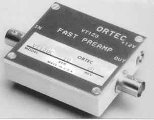
7 1 ORTEC MODEL VT120 FAST TIMING PREAMPLIFIER 1. DESCRIPTION The VT120 preamplifier is a high-performance, wide-bandwidth preamplifier designed for boosting very fast linear signals from photomultipliers, electron multipliers, silicon surface-barrier detectors, and other detectors used in fast timing applications. The rise time on all versions is <1 ns with a 5-V output, enabling excellent timing resolution. The VT120 is a single-channel unit in a small preamp package. It is available with a gain of 200, noninverting (A version); a gain of 200, inverting (B version); or a gain of 20, noninverting (C version). BNC connectors are used for signal connections on the VT120. A cable is available (Model C-VT120) for connecting power between the Model VT120 and conventional preamplifier power outputs using Amphenol-type connectors. 2. SPECIFICATIONS 2.1. PERFORMANCE GAIN (10% gain tolerance on all versions): A Version 200, noninverting. B Version 200, inverting. C Version 20, noninverting. RISE TIME #1 ns. NOISE #20 :V rms equivalent input noise. BANDWIDTH 10 to 350 MHz. OUTPUT RANGE 0 to -5 V with 50-S load. INPUT BNC connector; input impedance 50 S. OUTPUT BNC connector; 0 to -5 V output with a 50-S load. Output impedance #1 n ELECTRICAL AND MECHANICAL POWER REQUIRED +12 V, 50 ma (uses LEMO power connector that is compatible with accessory cable C-VT120). DIMENSIONS Aluminum housing 5.8 X 5.1 X 1.6 cm (2.3 X 2.0 X 0.63 in.). WEIGHT 0.2 kg (0.4 lb) ACCESSORIES C-VT120 cable assembly with connections between VT120 power input (LEMO) and Amphenol-type preamplifier power connectors that are compatible with other ORTEC NIM-standard modules.
8 2 3. INSTALLATION 3.1. GENERAL The VT120 contains no internal power supply and must obtain power from a NIM-standard bin and power supply, usually by connecting the C-VT120 accessory power cable between the VT120 and a NIM-standard module with a mating Amphenol-type preamp power connector. The bin and power supply should be turned Off when modules are inserted or removed. The power supply voltages should be checked after modules are inserted. Ensure that the VT120 has sufficient cooling air circulating to prevent any localized heating of the solid-state circuitry used throughout the unit. The VT120 should not be subjected to temperatures in excess of 50 C. 4. CIRCUIT DESCRIPTION The VT120 preamplifier is available in three versions. The "A" version has a noninverting gain of 200, the "B" version has an inverting gain of 200, and the "C" version has a noninverting gain of 20. The schematic diagram for each version is attached at the end of this manual. The schematic diagram for the VT120A at the end of this manual shows that the "A" version has five gain stages, Q1 through Q4, connected in the Common-Emitter configuration and 05 connected in the Emitter-Follower configuration. Each stage is ac-coupled to isolate bias voltages and to strongly reject low- frequency components. Input protection is furnished by diode D1. Consider the first stage formed around 01. Resistor R2 furnishes base-injection bias for the transistor, the series combination C2 and R3 provides shunt feedback, and resistor R4 is an unbypassed emitter resistor which, along with C3, peaks the highfrequency response of the stage. Each of the other Common-Emitter stages operates in a similar manner with specific component values set for optimum gain distribution and rise time. The final two Common-Emitter stages, Q3 and Q4, have variable peaking capacitors, C20 and C21, which are set in test to give an overall rise time of <1 ns. Transistor 05 is connected in the Emitter-Follower configuration and provides excellent output drive capability, 0 to -5 V, and low output impedance, <1 S. The schematic diagram of the VT120B is attached at the end of this manual. The "B" version has one less Common-Emitter amplifier stage than does the "A" version. This causes an overall signal inversion from input to output. The operation of each stage is similar to that of the "A", version except for the distribution of gain and rise time among the various preamplifier stages. Peaking capacitors C16 and C17 are set in test to give an overall rise time <1 ns. The schematic diagram of the VT120C is also attached at the end of this manual. The "C" version has two less Common-Emitter amplifier stages than does the "A" version. There is no signal inversion from input to output, and the overall gain is nominally 20. The operation of each stage is similar to that of the "A" version except for the distribution of gain and rise time among the various preamplifier stages. Peaking capacitors C3 and C7 are set in test to give an overall rise time <1 ns. The VT120 Fast Timing Preamplifier requires very little maintenance other than routine removal of dust and tightening of mechanical connections. 5. MAINTENANCE
9 3
10 4
11 5
Model 4001A Modular System Bin Operating and Service Manual
 Model 4001A Modular System Bin Operating and Service Manual Printed in U.S.A. ORTEC Part No. 733740 0704 Manual Revision D $GYDQFHG0HDVXUHPHQW7HFKQRORJ\,QF a/k/a/ ORTEC, a subsidiary of AMETEK, Inc. WARRANTY
Model 4002D NIM Bin Power Supply Operating and Service Manual
 Model 4002D NIM Bin Power Supply Operating and Service Manual Printed in U.S.A. ORTEC Part No. 740300 1202 Manual Revision J Advanced Measurement Technology, Inc. a/k/a/ ORTEC, a subsidiary of AMETEK,
PCM-7140 Pulsed Current Source Operation Manual
 PCM-7140 Pulsed Current Source Operation Manual Directed Energy, Inc. 1609 Oakridge Dr., Suite 100, Fort Collins, CO 80525 (970) 493-1901 sales@ixyscolorado.com www.ixyscolorado.com Manual Document 7650-0031
PIM-Mini Pulsed Current Source Operation Manual
 PIM-Mini Pulsed Current Source Operation Manual Directed Energy, Inc. 1609 Oakridge Dr., Suite 100, Fort Collins, CO 80525 (970) 493-1901 sales@ixyscolorado.com www.ixyscolorado.com Manual Document 7650-0007
DCS-E 1kW Series, DLM-E 3kW & 4kW Power Supplies
 DCS-E 1kW Series, DLM-E 3kW & 4kW Power Supplies M51A Option: Isolated Analog Programming Manual Power Supplies Elgar Electronics Corporation 9250 Brown Deer Road San Diego, CA 92121-2294 1-800-73ELGAR
User s Guide. RP7000S Series Single-Ended Active Probe. Nov RIGOL Technologies, Inc.
 User s Guide RP7000S Series Single-Ended Active Probe Nov. 2013 RIGOL Technologies, Inc. Guaranty and Declaration Copyright 2013 RIGOL Technologies, Inc. All Rights Reserved. Trademark Information RIGOL
OPERATING AND SERVICE MANUAL. Universal Interface Device 47
 OPERATING AND SERVICE MANUAL Universal Interface Device 47 MAGNA-POWER ELECTRONICS, INC. 39 ROYAL ROAD, FLEMINGTON, NJ 08822 May 24, 2012 SAFETY NOTICE Universal Interface Device 47 (UID46) connects
HV-CS kv Edge Mount Triaxial Jack
 Keithley Instruments 28775 Aurora Road Cleveland, Ohio 44139 1-800-935-5595 http://www.tek.com/keithley HV-CS-1589 3 kv Edge Mount Triaxial Jack Installation Information Description The Keithley Instruments
Model P4017 Single Channel USB Oscilloscope. Quick Start Guide
 Model P4017 Single Channel USB Oscilloscope Quick Start Guide General Warranty BNC warrants that the product will be free from defects in materials and workmanship for 3 years from the date of purchase
Model 2460-KIT. Screw Terminal Connector Kit. Description / September 2014 *P * 1
 Keithley Instruments 28775 Aurora Road Cleveland, Ohio 44139 1-800-935-5595 http://www.keithley.com Model 2460-KIT Screw Terminal Connector Kit Description The Model 2460-KIT Screw Terminal Connector Kit
OPERATING AND SERVICE MANUAL. Universal Interface Device 47
 OPERATING AND SERVICE MANUAL Universal Interface Device 47 MAGNA-POWER ELECTRONICS, INC. 39 ROYAL ROAD, FLEMINGTON, NJ 08822 May 24, 202 SAFETY NOTICE Universal Interface Device 47 (UID47) connects two
3-4 SAS/SATA II HDD Canister Entry version USER S MANUAL XC-34D1-SA10-0-R. Document number: MAN A
 3-4 SAS/SATA II HDD Canister Entry version XC-34D1-SA10-0-R USER S MANUAL Document number: MAN-00077-A ii Preface Important Information Warranty Our product is warranted against defects in materials and
SATA II HDD Canister KISS DA 435 Quick Reference Guide
 SATA II HDD Canister KISS DA 435 Quick Reference Guide If it s embedded, it s Kontron 1. Table of Contents SATA II HDD Canister KISS DA 435 1. Table of Contents 1. Table of Contents... 1 2. Important Information...
This 4200-RM Rack Mount Kit is for installation in 4200-CAB series cabinets only.
 Keithley Instruments, Inc. 28775 Aurora Road Cleveland, Ohio 44139 (440) 248-0400 Fax: (440) 248-6168 www.keithley.com Model 4200-RM Rack Mount Kit Packing List Introduction NOTE This 4200-RM Rack Mount
OLS Series Light Sources, OPM Series Optical Power Meters, and Related Test Kits User s Guide
 OLS Series Light Sources, OPM Series Optical Power Meters, and Related Test Kits User s Guide 2004-2009, AFL Telecommunications, all rights reserved. COM4-00-1001 Revision E, 2009-06-16 Specifications
Model 7705 Control Module
 www.keithley.com Model 7705 Control Module User s Guide PA-696 Rev. D / October 2006 A G R E A T E R M E A S U R E O F C O N F I D E N C E Safety Precautions The following safety precautions should be
Model 2657A-LIM-3 LO Interconnect Module
 Keithley Instruments, Inc. 28775 Aurora Road Cleveland, Ohio 44139 1-888-KEITHLEY http://www.keithley.com Model 2657A-LIM-3 LO Interconnect Module User's Guide Description The Model 2657A-LIM-3 LO Interconnect
CVU-200-KIT. 200 V Bias Tee Kit. Description. Parts list / October 2014 *P A* 1
 Keithley Instruments 28775 Aurora Road Cleveland, Ohio 44139 1-800-935-5595 http://www.keithley.com CVU-200-KIT 200 V Bias Tee Kit Description The CVU-200-KIT Bias Tee Kit consists of three 2600-RBT-200
CVU-3K-KIT. 3 kv Bias Tee Kit. Description. Parts list / October 2014 *P * 1
 Keithley Instruments 28775 Aurora Road Cleveland, Ohio 44139 1-800-935-5595 http://www.keithley.com CVU-3K-KIT 3 kv Bias Tee Kit Description The CVU-3K-KIT Bias Tee Kit consists of three bias tees for
Model 2600B-PM V Protection Module with 1 A Clamp. Description / April 2015 *PPA * 1
 Keithley Instruments 28775 Aurora Road Cleveland, Ohio 44139 1-800-935-5595 http://www.keithley.com Model 2600B-PM-1 200 V Protection Module with 1 A Clamp Description The Model 2600B-PM-1 200 V Protection
PS8 - II. Professional Power Sequencer. User s Manual
 PS8 - II Professional Power Sequencer User s Manual IMPORTANT SAFETY INSTRUCTIONS READ FIRST This symbol, whenever it appears, alerts you to the presence of uninsulated dangerous voltage inside the enclosure.
COOPER POWER SERIES. 600 A U-OP visible break connector system operation instructions. Deadbreak Apparatus Connectors MN650022EN
 Deadbreak Apparatus Connectors MN650022EN COOPER POWER Effective March 2016 Supersedes S600-14-1 June 2010 SERIES 600 A U-OP visible break connector system operation instructions DISCLAIMER OF WARRANTIES
Model 2380 Rack-Mount Kit
 Keithley Instruments 28775 Aurora Road Cleveland, Ohio 44139 1-800-935-5595 http://www.tek.com/keithley Model 2380 Rack-Mount Kit Installation Instructions Introduction The Model 2380 Fixed Rack-Mount
D-Pack 6 Classic ORDERCODE 50315
 D-Pack 6 Classic ORDERCODE 50315 Congratulations! You have bought a great, innovative product from Showtec. The Showtec D-Pack 6 Classic brings excitement to any venue. Whether you want simple plug-&-play
Model 2380 Rack-Mount Kit
 Keithley Instruments 28775 Aurora Road Cleveland, Ohio 44139 1-800-935-5595 http://www.tek.com/keithley Model 2380 Rack-Mount Kit Installation Instructions Introduction The Model 2380 Fixed Rack-Mount
Contents. HP E1586A Rack Mount Terminal Panel User s Manual
 Contents HP E1586A Rack Mount Terminal Panel User s Manual Description... 5 Connecting to VXIbus Instruments... 5 Interconnect Cables... 5 Terminal Block Connections... 6 Using the Terminal Panel for Reference
XBDM. 1015LV, 1020LV, 1030LV, 1020HV Models USER & INSTALLATION MANUAL BYPASS DISTRIBUTION MODULE
 XBDM 1015LV, 1020LV, 1030LV, 1020HV Models USER & INSTALLATION MANUAL www.xpcc.com 2013 Xtreme Power Conversion Corporation. All rights reserved. Table of Contents IMPORTANT SAFETY INSTRUCTIONS:... 4 INTRODUCTION...
Owner s Instruction Manual
 Owner s Instruction Manual Advanced Healthcare Telephone Model 5150 Contents IMPORTANT SAFETY INSTRUCTIONS...3 BOX CONTENTS...4 FEATURES...4 ON/OFF SWITCH...4 DIAL BUTTONS...4 RECEIVER VOLUME CONTROL...4
Model 3106D HV Power Supply
 9231583A Model 3106D HV Power Supply User s Manual Copyright 2004, Canberra Industries, Inc. All rights reserved. The material in this document, including all information, pictures, graphics and text,
1-36V, 0-3A DC Power Supply
 1550 1-36V, 0-3A DC Power Supply User Manual Safety Summary The following safety precautions apply to both operating and maintenance personnel and must be followed during all phases of operation, service,
Model 4200-CVU-PWR. Parts Package. Introduction. PA-977 Rev. C / September 2016 *PPA-977C* 1
 Keithley Instruments 28775 Aurora Road Cleveland, Ohio 44139 1-800-935-5595 http://www.tek.com/keithley Model 4200-CVU-PWR Parts Package Introduction The Model 4200-CVU-PWR C-V Power Package for both the
Kramer Electronics, Ltd. USER MANUAL. Model: VP-200XLN. XGA Line Amplifier / DA
 Kramer Electronics, Ltd. USER MANUAL Model: VP-200XLN XGA Line Amplifier / DA Contents Contents 1 Introduction 1 2 Getting Started 1 2.1 Quick Start 1 3 Overview 3 4 Your VP-200XLN XGA Line Amplifier /
9040/9040UK. Users Manual. Phase Rotation Indicator
 9040/9040UK Phase Rotation Indicator Users Manual PN 2438546 April 2005 2005 Fluke Corporation. All rights reserved. Printed in China All product names are trademarks of their respective companies. LIMITED
2260B-RMK-Series Rack Mount Kit
 Keithley Instruments, Inc. 28775 Aurora Road Cleveland, Ohio 44139 1-888-KEITHLEY http://www.keithley.com Assembly and Mounting Instructions Introduction The 2260B-RMK-Series Rack Mount Kit is suited for
User's Guide. Extech AM A AC Analog Clamp Meter
 User's Guide Extech AM300 300A AC Analog Clamp Meter Introduction Congratulations on your purchase of the Extech AM300 Analog Clamp Meter. This device measure AC Voltage and Current, DC Voltage, and Resistance.
DLS 5405 Operating Manual High Bandwidth Noise Injection Unit
 DLS 5405 Operating Manual High Bandwidth Noise Injection Unit October 2005 71-000042 Revision B DLS 5405 Operating Manual Copyright Notice 2005 Spirent Communications Manual Part Number 71-000042 Revision
EASON TECHNOLOGY. IO8 & IO24 Break-Out Module
 EASON TECHNOLOGY IO8 & IO24 Break-Out Module p/n 50-00180-01 Revision1.2 Eason Technology, Inc. 7975 Cameron Dr. Bldg 300 Windsor, CA 95492 Phone (707) 837-0120 FAX (707) 837-2742 http://www.eason.com
Instructions. P MHz 10X Passive Probe
 Instructions P6112 100 MHz 10X Passive Probe 070-9694-00 Copyright Tektronix, Inc. All rights reserved. Tektronix products are covered by U.S. and foreign patents, issued and pending. Information in this
COOPER POWER SERIES. Input/Output (I/O) module installation instructions. Voltage Regulators MN225067EN
 module installation instructions. Voltage Regulators MN225067EN") Voltage Regulators MN225067EN Effective November 2016 Supersedes June 2014 (S225-70-13) COOPER POWER Input/Output (I/O) module installation instructions SERIES DISCLAIMER OF WARRANTIES AND LIMITATION OF
Voltage Regulators MN225067EN Effective November 2016 Supersedes June 2014 (S225-70-13) COOPER POWER Input/Output (I/O) module installation instructions SERIES DISCLAIMER OF WARRANTIES AND LIMITATION OF
Series 8000 RF Signal Switch Solution
 RF Signal Switch Solution Operation Manual Operation Manual, Part Number 07508000 006, Rev. B, Oct 7, 2014 All technical data and specifications in this publication are subject to change without prior
SP-1009D. 1x9 Dual Link DVI Distribution Amplifier. User Manual. Made in Taiwan
 SP-1009D 1x9 Dual Link DVI Distribution Amplifier User Manual Made in Taiwan Safety and Notice The SP-1009D 1x9 Dual Link DVI Distribution Amplifier has been tested for conformance to safety regulations
E2K-F. Flat Capacitive Sensor with a Thickness of Only 10 mm. Flat Proximity Sensor. Ordering Information. Sensors [Refer to Dimensions on page 4.
 Flat Proximity Sensor EK-F CSM_EK-F_DS_E Flat Capacitive Sensor with a Thickness of Only mm Flat Sensor with excellent space efficiency. (Model with built-in Amplifier is only mm thick.) Direct mounting
OPERATOR MANUAL OSD461A/OSD463A AUDIO FIBER OPTIC TRANSMISSION SYSTEM
 OPERATOR MANUAL OSD461A/OSD463A AUDIO FIBER OPTIC TRANSMISSION SYSTEM OSD461A/OSD463A AUDIO FIBER OPTIC TRANSMISSION SYSTEM Document No. 101052 Rev. 01 PAGE 2 INDEX 1 1 TECHNICAL SUMMARY... 4 1.1 BRIEF
Line Impedance Stabilization Network (LISN)
") Model 3816/2 Line Impedance Stabilization Network (LISN) User Manual ETS-Lindgren Inc. reserves the right to make changes to any product described herein in order to improve function, design, or for any
Model 3816/2 Line Impedance Stabilization Network (LISN) User Manual ETS-Lindgren Inc. reserves the right to make changes to any product described herein in order to improve function, design, or for any
Model 8020-STC. Kelvin Standard Triaxial Connector Card. Description / October 2014 *P * 1
 Keithley Instruments 28775 Aurora Road Cleveland, Ohio 44139 1-800-935-5595 http://www.keithley.com Model 8020-STC Kelvin Standard Triaxial Connector Card Description The Model 8020-STC Kelvin Standard
1:4 3GSDI Splitter. User Manual EXT-3GSDI-144. Release A5
 1:4 3GSDI Splitter EXT-3GSDI-144 User Manual Release A5 Important Safety Instructions 1. Read these instructions. 2. Keep these instructions. 3. Heed all warnings. 4. Follow all instructions. 5. Do not
Kramer Electronics, Ltd. USER MANUAL
 Kramer Electronics, Ltd. USER MANUAL Models: VP-200NK, 1:2 High Resolution XGA DA VP-300NK, 1:3 High Resolution XGA DA VP-400NK, 1:4 High Resolution XGA DA Contents Contents 1 Introduction 1 2 Getting
Model 8020-KHV. Kelvin Keithley Triaxial Connector Card. Description / October 2014 *P * 1
 Keithley Instruments 28775 Aurora Road Cleveland, Ohio 44139 1-800-935-5595 http://www.keithley.com Model 8020-KHV Kelvin Keithley Triaxial Connector Card Description The Model 8020-KHV Keithley HV Connector
Speaker Selectors Models SSW-L4 EX and SSW-L6 EX. User Manual. SSW-L4 EX (bottom) and SSW-L6 EX (top)
 and SSW-L6 EX (top)") Speaker Selectors Models SSW-L4 EX and SSW-L6 EX User Manual SSW-L4 EX (bottom) and SSW-L6 EX (top) Table of Contents Important Safety Precautions...2 What s Included...2 Introduction... 3 Front Panel...
Speaker Selectors Models SSW-L4 EX and SSW-L6 EX User Manual SSW-L4 EX (bottom) and SSW-L6 EX (top) Table of Contents Important Safety Precautions...2 What s Included...2 Introduction... 3 Front Panel...
PDS8u POWER DISTRIBUTION SYSTEM USER'S MANUAL
 PDS8u POWER DISTRIBUTION SYSTEM USER'S MANUAL 1 IMPORTANT SAFETY INSTRUCTION READ FIRST This symbol, whenever it appears, alerts you to the presence of uninsulated dangerous voltage inside the enclosure-voltage
87421/22A Power Supply. Operating and Service Manual
 87421/22A Power Supply Operating and Service Manual Agilent Part Number: 87421-90001 Printed in USA April 2001 Supersedes: September 1998 Notice The information contained in this document is subject to
TETRIS 2500 High Impedance Active Probe. Instruction Manual
 TETRIS 2500 High Impedance Active Probe Instruction Manual Copyright 2018 PMK GmbH All rights reserved. Information in this publication supersedes that in all previously published material. Specifications
MTS-2000 USER S MANUAL
 MTS-2000 USER S MANUAL USER s MANUAL - March 2010 MTS-2000 METER TEST SYSTEM Pay special attention to the warnings and safety instructions that accompany the above symbol wherever it is found within this
OPERATOR MANUAL OSD361 FIBER OPTIC CCTV TRANSMITTER MODULE
 OPERATOR MANUAL OSD361 FIBER OPTIC CCTV TRANSMITTER MODULE OSD361 FIBER OPTIC CCTV TRANSMITTER MODULE Document No. 10102303 PAGE 1 INDEX 1 1 TECHNICAL SUMMARY... 3 1.1 BRIEF DESCRIPTION...3 1.1.1 OVERVIEW...
Single Phase Vacuum Capacitor Switch. UltraVacLT 15kV 95kV or 125kV BIL
 Trinetics UltraVacLT Single Phase Vacuum Capacitor Switch Installation and Operation Instructions UltraVacLT 15kV 95kV or 125kV BIL UltraVacLT 27kV 125kV or 150kV BIL Hubbell has a policy of continuous
Kramer Electronics, Ltd. USER MANUAL. Model: VS-4x4FW. 4x4 FireWire Switcher
 Kramer Electronics, Ltd. USER MANUAL Model: VS-4x4FW 4x4 FireWire Switcher Contents Contents 1 Introduction 1 2 Getting Started 1 2.1 Quick Start 1 3 Overview 3 4 Your FireWire Switcher 4 5 Using the FireWire
User s Guide. 600A AC Clamp Meter. Model 38387
 User s Guide 600A AC Clamp Meter Model 38387 Safety International Safety Symbols This symbol, adjacent to another symbol or terminal, indicates the user must refer to the manual for further information.
Speaker Selectors Models SSW-4 and SSW-6. User Manual
 Speaker Selectors Models SSW-4 and SSW-6 User Manual (SSW-4) (SSW-6) Table of Contents Important Safety Precautions... 2 What s Included... 2 Introduction... 3 Front Panel... 3 Rear Panel... 3 Typical
Series RMT Hot Runner Controller Setup and Operation Manual
 Series RMT Hot Runner Controller Setup and Operation Manual Littlefuse is a registered trademark of Littlefuse, Inc. G is a registered trademark of the DME Corporation. SafeChange is a trademark of Athena
HDMI Extender over Cat5e/6
 Statement Thanks for purchasing this product, please read this user manual carefully before using this product.in the constant effort to improve our product, we reserve the right to make functions or parameters
Resolver to Digital Expansion Board
 Resolver to Digital Expansion Board Catalog No. EXB009A01 Installation and Operating Manual 6/98 MN1313 Table of Contents Section 1 General Information............................. 1-1 Introduction....................................
MCCB-500 MOLDED-CASE CIRCUIT BREAKER TESTER
 MCCB-500 MOLDED-CASE CIRCUIT BREAKER TESTER USER S MANUAL Vanguard Instruments Company, Inc. 1520 S. Hellman Ave. Ontario, California 91761, USA TEL: (909) 923-9390 FAX: (909) 923-9391 January 2015 Revision
G3NE. Model Number Structure. Solid State Relays. Model Number Legend. Compact, Low-cost, SSR Switching 5 to 20 A
 Solid State Relays CSM DS_E_4_1 Compact, Low-cost, SSR Switching 5 to 20 A Wide load voltage range: 75 to 264 VAC. Both 100-V and 200-V loads can be handled with the same model. Dedicated, compact aluminum
Kramer Electronics, Ltd. USER MANUAL. Model: VP-111. XGA Line Driver
 Kramer Electronics, Ltd. USER MANUAL Model: VP-111 XGA Line Driver Contents Contents 1 Introduction 1 2 Getting Started 1 3 Overview 1 4 Your VP-111 XGA Line Driver 2 5 Connecting the VP-111 XGA Line Driver
Kramer Electronics, Ltd. USER MANUAL. Model: VM-50AN. 1:5 Audio Distributor
 Kramer Electronics, Ltd. USER MANUAL Model: VM-50AN 1:5 Audio Distributor Contents Contents 1 Introduction 1 2 Getting Started 1 2.1 Quick Start 1 3 Overview 3 4 Your Audio VM-50AN 1:5 Distributor 4 5
Operating Instructions
 Model No.: HDIP01_02 Operating Instructions Thanks for purchasing our product. Please be sure to read this instruction manual Carefully before using our product. Introduction The HDMI-IP Extender allows
Dual Link DVI Extender
 2x Dual Link DVI Extender EXT-2DVI-CATDL User Manual Release A4 2x Dual Link DVI Extender Important Safety Instructions 1. Read these instructions. 2. Keep these instructions. 3. Heed all warnings. 4.
700 Series 200 Amp Clamp Meters
 700 Series 200 Amp Clamp Meters #61-700 #61-701 #61-702 1 2 3 6 5 7 4 8 1. Non-contact voltage (NCV) (#61-701 and #61-702) With the NCV tab on the tip of the clamp close to an AC voltage, press the NCV
Automated Tuner System Power Distribution Hub
 User Guide Automated Tuner System Power Distribution Hub Model MT1020B MT1020-340 (Rev B) 12/11 User Guide Automated Tuner System Power Distribution Hub Model MT1020B 2900 Inland Empire Boulevard Ontario,
BS 181 SINGLE CHANNEL POWER SUPPLY USER MANUAL
 BS 181 SINGLE CHANNEL POWER SUPPLY USER MANUAL Issue 2011 ASL Intercom BV DESIGNED & MANUFACTURED BY: ASL Intercom B.V. Zonnebaan 42 3542 EG Utrecht The Netherlands Tel: +31 (0)30 2411901 Fax: +31 (0)30
OPERATOR MANUAL OSD381 FIBER OPTIC CCTV TRANSMITTER MODULE
 OPERATOR MANUAL OSD381 FIBER OPTIC CCTV TRANSMITTER MODULE OSD381 FIBER OPTIC CCTV TRANSMITTER MODULE Document No. 10100902 PAGE 1 INDEX 1 1 TECHNICAL SUMMARY... 3 1.1 BRIEF DESCRIPTION...3 1.1.1 OVERVIEW...
DVI Detective. User Manual EXT-DVI-EDIDN. Release A3
 DVI Detective EXT-DVI-EDIDN User Manual Release A3 Important Safety Instructions 1. Read these instructions. 2. Keep these instructions. 3. Heed all warnings. 4. Follow all instructions. 5. Do not use
Series RMA Hot Runner Controller Setup and Operation Manual
 Series RMA Hot Runner Controller Setup and Operation Manual Littlefuse is a registered trademark of Littlefuse, Inc. G is a registered trademark of the DME Corporation. SafeChange is a trademark of Athena
User Manual TLS HDMI Switch Splitter 3/2
 875224 User Manual TLS HDMI Switch Splitter 3/2 IR SW B A 3 2 1 HDMI IN HDMI OUT DC 5V 1 2 3 A B 8 875224 HDMI Switch Splitter 3/2 Thank you for purchasing this product. For optimum performance and safety,
Sonic Ruptor 400. User Manual
 Sonic Ruptor 400 User Manual Data herein has been verified and validated. It is believed adequate for the intended use of the instrument. If the instrument or procedures are used for purposes over and
Broadband Automatic Disconnect Switch. User Manual
 Reset/Test Primary/ Primary Broadband Automatic Disconnect Switch User Manual Local Power Remote Pwer Local 63V Fault Secondary Select Secondary 220V Normal 990-1929 09/2004 Introduction Introduction
SmartBoom PRO PHS-SB100-4F, PHS-SB100-5M, PHS-SB100-U, PHS-SB200-4F, PHS-SB200-5M, PHS-SB200-U. Operating Manual
 SmartBoom Operating Manual PRO PHS-SB100-4F, PHS-SB100-5M, PHS-SB100-U, PHS-SB200-4F, PHS-SB200-5M, PHS-SB200-U Thank You We at Pliant Technologies, LLC want to thank you for purchasing the SmartBoom PRO
Lotus DX. sit-stand workstation. assembly and operation instructions. MODEL # s: LOTUS-DX-BLK LOTUS-DX-WHT
 Lotus DX assembly and operation instructions sit-stand workstation MODEL # s: LOTUS-DX-BLK LOTUS-DX-WHT safety warnings 13.6 Kg 30 lbs. 2.2 Kg 5 lbs. safety instructions/warning Read and follow all instructions
4 Port USB Power Hub. Model: JH-800 USER MANUAL
 by 4 Port USB Power Hub Model: JH-800 USER MANUAL BEFORE INSTALLING AND USING THE PRODUCT, PLEASE READ THE INSTRUCTIONS THOROUGHLY, AND RETAIN THEM FOR FUTURE REFERENCE. Charging Port PRODUCT OVERVIEW
The PST-6. Owners Manual 1
 The PST-6 Owners Manual 1 Introduction Thank you for purchasing the Furman Power Station-6 Power Conditioner. For over 30 years, Furman has pioneered the development of AC power products for the most demanding
User s Guide. POWERVAR Single Phase Power Conditioners
 POWERVAR Single Phase Power Conditioners User s Guide Industrial Conditioners GPI Series B Conditioners GPI Series 1 Conditioners 2-15 kva Single Phase Conditioners GPI Series 1 Conditioners RoHS Compliant
Global Water Instrumentation, Inc.
 Global Water Instrumentation, Inc. 11390 Amalgam Way Gold River, CA 95670 T: 800-876-1172 Int l: (916) 638-3429, F: (916) 638-3270 PRODUCT NAME: 3101 Conductivity Controller - 1 - Global Water s Conductivity
G3B/G3BD. Model Number Structure. Ordering Information. Solid State Relays Model Number Legend. List of Models
 Solid State Relays G3@-VD CSM_G3B_G3BD_DS_E_5_1 International Standards for G3B Series, Same Profile as MK Power Relays Shape-compatible with mechanical relays. Certified by UL, CSA, and VDE (models numbers
200B-G Tone Probe. 200EP-G Tone Probe INSTRUCTION MANUAL. with Adjustable Volume
 INSTRUCTION MANUAL English...1 Français...9 Español...17 Deutsch...25 Italiano...33 Português do Brasil...41 200B-G Tone Probe with Adjustable Volume 200EP-G Tone Probe with Adjustable Volume, Visual Signal
MP3 Speaker USER GUIDE
 MP3 Speaker USER GUIDE Jazwares, Inc. 2012 CONTENTS Please read the instructions along with the Speaker carefully before you use it, so that you can operate it conveniently. WELCOME, Warnings & Safety
850A/B Contact Chatter Detector User Manual
 Trig-Tek 850A/B Contact Chatter Detector User Manual Publication No. 980972 Rev. B Astronics Test Systems Inc. 4 Goodyear, Irvine, CA 92618 Tel: (800) 722-2528, (949) 859-8999; Fax: (949) 859-7139 atsinfo@astronics.com
TOUPCAM QUICK GUIDE INSTALLATION MANUAL
 TOUPCAM QUICK GUIDE INSTALLATION MANUAL January 2013 1 WARNING! TO AVOID THE RISK OF FIREOR ELECTRICAL SHOCK. NEVER EXPOSE THIS PRODUCTTOWATEROR OPERATEIN AHIGH HUMIDITYENVIRONMENT. Keep camera away from
Solid State Relays with Failure Detection Function
 Solid State Relays with Failure Detection Function CSM DS_E_2_1 Refer to Safety Precautions for All Solid State Relays. Detects failures in SSR used for heater temperature control and simultaneously outputs
RESIDENTIAL OPERATOR MOTOR CONTROL BOARD REPLACEMENT INSTRUCTIONS
 READ THIS MANUAL CAREFULLY BEFORE BEGINNING INSTALLATION RESIDENTIAL OPERATOR MOTOR CONTROL BOARD REPLACEMENT INSTRUCTIONS PRODUCT FEATURES MODELS: IIA SPRINT 310/510/710 200/250 2000 SERIES 3000 SERIES
HDMI to 3GSDI Converter
 HDMI to 3GSDI Converter EXT-HD-3G-C User Manual Release A2 Important Safety Instructions 1. Read these instructions. 2. Keep these instructions. 3. Heed all warnings. 4. Follow all instructions. 5. Do
Kramer Electronics, Ltd. USER MANUAL. Models: RC-2C, Wall Plate / RS-232 / IR Controller RC-2, Wall Plate / RS-232 Controller
 Kramer Electronics, Ltd. USER MANUAL Models: RC-2C, Wall Plate / RS-232 / IR Controller RC-2, Wall Plate / RS-232 Controller Contents Contents 1 Introduction 1 2 Getting Started 1 3 Overview 2 4 Your RC-2C/RC-2
LUDLUM MODEL ALPHA/BETA DETECTOR. August 2015
 LUDLUM MODEL 43-147 ALPHA/BETA DETECTOR August 2015 LUDLUM MODEL 43-147 ALPHA/BETA DETECTOR August 2015 STATEMENT OF WARRANTY Ludlum Measurements, Inc. warrants the products covered in this manual to be
Series 8000 RF Signal Switch Solution
 RF Signal Switch Solution Operation Manual Operation Manual, Part Number 07508000-006, Rev. A, May 17, 2013 All technical data and specifications in this publication are subject to change without prior
VELOCICALC Air Velocity Meter
 ENERGY AND COMFORT Ventilation Testing VELOCICALC Air Velocity Meter Model 9525 Operation and Service Manual Copyright TSI Incorporated / May 2007 / All rights reserved. Address TSI Incorporated / 500
WAXPENCIL PRO Owner & Operator s Manual
 WAXPENCIL PRO Owner & Operator s Manual Model No. Voltage Frequency 9995337 120V 50 60 Hz 9995338 230V 50 60 Hz Table of Contents DESCRIPTION PAGE Safety... 2 Technical Data... 3 Installation Instructions...
OPERATION MANUAL SERIES BORESCOPES INSTRUMENT TECHNOLOGY, INC. POB 381, Westfield, MA Airport Road, Westfield, MA 01085
 OPERATION MANUAL SERIES 123000 BORESCOPES INSTRUMENT TECHNOLOGY, INC. POB 381, Westfield, MA 01086 33 Airport Road, Westfield, MA 01085 Tel: (413) 562-3606 Fax: (413) 568-9809 Email: iti@scopes.com www.scopes.com
VIP-804 QUAD ENHANCED NETWORK AUDIO PORT
 ISSUE 6 VIP-804 QUAD ENHANCED NETWORK AUDIO PORT INTRODUCTION The VIP-804 Quad Enhanced Network Audio Port enables voice access to four zones of one-way paging over an IP network, allowing page zones to
Kramer Electronics, Ltd. USER MANUAL. Model: VM-80HP. 1:8 Stereo Headphone Distributor
 Kramer Electronics, Ltd. USER MANUAL Model: VM-80HP 1:8 Stereo Headphone Distributor Contents Contents 1 Introduction 1 2 Getting Started 1 3 Overview 2 4 Your VM-80HP 1:8 Stereo Headphone Distributor
Kramer Electronics, Ltd. USER MANUAL. Model: VM-2HDCP. 1:2 DVI Distributor
 Kramer Electronics, Ltd. USER MANUAL Model: VM-2HDCP 1:2 DVI Distributor Contents Contents 1 Introduction 1 2 Getting Started 1 2.1 Quick Start 2 3 Overview 3 3.1 About HDCP 3 3.2 Defining EDID 4 3.3 Recommendations
Installation and Operation
 S&C TripSaver II Cutout-Mounted Recloser Outdoor Distribution (15 kv and 25 kv) Cordless Power Module Installation and Operation Table of Contents Section Page Section Page Introduction Qualified Persons....