Software. SuperDrive G User's Manual. Phone: Fax: Web:
|
|
|
- Brandon Jones
- 5 years ago
- Views:
Transcription

1 Motors Automation Energy Transmission & Distribution Coatings Software SuperDrive G User's Manual

2 User's Manual Series: SuperDrive G2 Language: English Document: / 15 Publication Date: 05/2014
3 Contents Contents 1 SuperDrive G Getting Started 6 1 Welcome Main Features What's New Copyright... Notice 13 5 Safety... Warning 13 6 User's... Manual - PDF 13 3 Installation Instructions 14 1 Before... Installing 14 2 Minimum... Requirements 14 3 Supported... Drives 15 4 Java Runtime... Environment 19 5 Installing Uninstalling USB Driver Menus 27 1 Project New Open Close Save Export Import Print Project Information Exit Drive Identify Drive Communication... Setup 33 New Parameters... File 34 Edit Parameters... File 35 Remove Parameters... File 36 Read Parameters... from Drive 36 Write Parameters... to Drive 36 Monitor Parameters Monitor using Keypad Monitor Status Monitor Speed Reference Trend Remove Trend File Trace Remove Trace File Tools... 47
4 Contents Language Help Contents About Communication 49 1 Drive Parametrization Connecting... the Drive (USB) 55 3 Connecting... the Drive (USB - Virtual COM Port) 57 4 Connecting... the Drive (RS232) 69 5 Connecting... the Drive (RS485) 71 6 Connecting... the Drive (Bluetooth) 87 7 RS Cable USB Cable USB to... Serial Adapter Bluetooth... USB Adapter Before... Trying to Establish Communication Exception... During Monitoring Libraries JFreeChart jssc Index 109
5 SuperDrive G SuperDrive G Technical Support: Contact a local branch or representative. Contact Us Publication Date: 05/2014 Start Click the Welcome button to start. Welcome
6 Getting Started 2 Getting Started Welcome Main Features What's New Copyright Notice Safety Warning User's Manual - PDF 2.1 Welcome Welcome to SuperDrive G2! Thank you for using SuperDrive G2, a windows based graph tool for parameter setting, command and monitoring of drives. SuperDrive G2 is a computer tool for making the use of drives as easy and convenient as possible. SuperDrive G2 provides user-friendly tools for viewing, manipulating, and exchanging data with the drive. Data can be retrieved, changed and stored. The computer is connected to the drive using serial communication. 2.2 Main Features Online identification of connected drive; Offline configuration of drive; Parameter transfer from computer to the drive; Parameter transfer from drive to the computer; Offline editing of the parameters stored on the computer; Online editing of the parameters in drive; Monitoring of the drive status; Command operations (motor stop/run, jog, forward/reverse, local/remote, etc); Supports multiple databases for standard and special firmware version; RS232, RS485 and USB point-to-point serial communication; Graphical monitoring of parameters; Configuration, import and visualization of variables stored in Trace function of the drive (CFW-11 and SCA06); Project importation and exportation; Online help. NOTE! Some features are not available in all drives. 2.3 What's New SuperDrive G /21/2014 The following features were added:
7 Getting Started Communication with MW500 V1.5X; Communication with CFW100 via Bluetooth; Communication with CFW100 V2.2X; Communication with SCA06 V1.4X; Communication with CFW11 V5.4X; Communication with CFW11 V5.30; Communication with CFW11 V4.20; Communication with CFW11 V3.30; Communication with CFW11 V3.31; Communication with CFW11 V3.32; Communication with CFW11 V3.33. Minor changes: Correction of instability during printing parameters; Database correction of CFW500 V1.1X; Database correction of CFW500 V1.5X; Database correction of CFW700 V2.0X; Database correction of CFW701 V2.0X. SuperDrive G /06/2014 The following features were added: Communication with CFW100 V2.1X. Minor changes: Correction in Trace function where there was error in the read/write configuration, Fix reading of parameters that were not saved correctly when the reading was taken before saving the project. SuperDrive G /03/2013 The following features were added: Compatible with Windows 8 x86, Windows 8 x64 Minor changes: Indication on the parameter list of what has changed (different from standard); Fixed the window of Speed Reference to CFW100, CFW500, CFW700/701, CFW11, CTW900, which presented incorrect values; Fixed the New File Parameters function (offline generation of files parameters with default values), where the parameters firmware version, rated current of the drive and rated voltage of the drive had incorrect values; Fixed the Trend function which stored incorrectly content 0 when reading error occurred; Communication with CFW701 V2.0x, database correction. SuperDrive G /07/2013
8 Getting Started The following features were added: Communication with CFW11 V5.1X. SuperDrive G /13/2013 The following features were added: Communication with CFW100 V2.0X. SuperDrive G /22/2013 The following features were added: Communication with CFW500 V1.5X; Communication with CFW700 V2.0X; Communication with CFW701 V2.0X; Communication with SSW7000 V1.2X. SuperDrive G /12/2013 The following features were added: Communication with CFW-11 V3.5X. SuperDrive G /05/2013 The following features were added: Communication with ECW500 V1.0X; Communication with CFW-11 V4.01; Communication with CFW-11 V4.10; Improved communication with drives (RS232 and RS485); Language change no longer requires program restart; Automatic loading of database on alternative language. Minor changes: Communication with CFW-11 V3.1x, database correction; Communication with CFW100 V1.1x, database correction; Communication with CTW900 V1.0x, database correction; Several improvements in Identify Drive and Communication Setup windows. SuperDrive G /05/2012 The following features were added: Communication with CFW100 V1.1X;
9 Getting Started Size and position of windows are saved; Project importation and exportation. Minor changes: Communication with CFW701 V1.2X, database correction. SuperDrive G /03/2012 The following features were added: Communication with CFW11 V3.1X; Communication with CFW700 V1.2X. Minor changes: Communication with CFW700 V1.0X, database correction. SuperDrive G /16/2012 The following features were added: Communication with CTW900 V1.0X; Communication with SCA06 V1.2X. SuperDrive G /05/2011 The following features were added: Communication with CFW500 V1.1X; Communication with CFW701 V1.2X; Communication with CFW-11 V3.11; Communication with CFW-11 V3.12. SuperDrive G /27/2011 The following features were added: Trend in the function and Trace, minimum, maximum and legend are now saved when the graph is closed; Communication with CFW-11 V2.46; Communication with CFW-11 V2.50; Communication with CFW-11 V2.51; Communication with CFW-11 V3.90. Minor changes: Communication with CFW-11 V3.0x, database correction; Communication with CFW700 V1.0x, database correction.
10 Getting Started SuperDrive G /27/2011 The following features were added: Offline programming. SuperDrive G /05/2010 The following features were added: Communication with CFW-11 V3.0x. SuperDrive G /22/2010 The following features were added: Communication with SSW7000 V1.1x; Communication with SSW-07 V1.4x; Communication with SSW-08 V1.4x; Compatible with Windows 7 x86, Windows 7 x64; Compatible with Windows Vista x86, Windows Vista x64; Compatible with Windows XP x86, Windows XP x64. SuperDrive G /20/2010 The following features were added: Communication with SCA06 V1.1x; Communication with SSW-06 V1.7x. SuperDrive G /10/2010 The following features were added: Communication with CFW700 V1.0x. SuperDrive G /05/2010 The following features were added: Communication with CFW-11 V2.0x; Communication with CFW-11 + PLC11-01 V1.4x; Communication with CFW-11 + PLC11-02 V1.4x. SuperDrive G2 8.40
11 Getting Started 09/08/2009 The following features were added: Identify Drive address selection, Write Parameters to Drive destination address selection; Communication with CFW-11 + PLC11-01 V1.2x; Communication with CFW-11 + PLC11-02 V1.2x; Communication with SSW-06 V1.6x. SuperDrive G /15/2009 The following features were added: Communication with CFW-11 + PLC11-02 V1.0x. SuperDrive G /18/2008 The following features were added: Communication with CFW-09 PM V12.0x; Communication with CFW-11 V1.6x. SuperDrive G /20/2008 The following features were added: Communication with CFW-11 V1.3x; Communication with CFW-11 + PLC11-01 V1.0x. SuperDrive G /16/2008 The following features were added: Trend function, Communication with CFW-09 PM V11.3x; Communication with SSW-07 V1.3x; Communication with SSW-08 V1.3x. SuperDrive G /31/2007 The following features were added: Communication with CFW-11 V1.1x; Communication with SSW-06 V1.4x. SuperDrive G2 8.20
12 Getting Started 08/01/2007 The following features were added: Communication with SSW-07 V1.2x; Communication with CFW-09 PM V10.0x; New baud rate for RS232: 4800 bps. Minor changes: Option "Always on Top" was removed from several windows; New layout in monitoring windows; It is no more necessary to reopen the project after changing Communication Setup. SuperDrive G /24/2007 Minor changes: Updated CFW-11 data base; New baud rate for RS232: bps. SuperDrive G /29/2007 The following features were added: Communication with CFW-11 V1.0x; USB point-to-point serial communication; Reference speed monitoring of CFW-11; Trace function; Language selection: English, Portuguese and Spanish. Minor changes: Monitor Parameters: a divider offers user-controlled resizing of two components: parameters and messages; Monitor Parameters: if the user press the right button of the mouse in the messages container, a small popup menu appears with the option to clean the messages; Monitor Parameters and Edit Parameters File: Ok and Cancel buttons were replaced with Close button; Monitor Keypad: validation of parameter value; Monitor Keypad: the user may now type a value directly into the parameter field; Always on top functionality is not selected any more when a window is opened; Parameters conversion for hexadecimal and binary now supported. SuperDrive G /20/2006 Initial Version: Automatic identification of connected drives; Parameter transfer from computer to the drive; Parameter transfer from drive to the computer; Offline editing of the parameters stored in files on the computer;
13 Getting Started Monitoring (visualization and change) of drive parameters; Monitoring of the drive status and command operations (motor stop/run, jog, forward/ reverse, local/remote, etc); Supports multiple databases for special firmware version; RS232 point-to-point serial communication; Online help. 2.4 Copyright Notice This computer program is protected by copyright law and international treaties. Unauthorized reproduction or distribution of this program, or any portion of it, may result in severe civil and criminal penalties, and will be prosecuted to the maximum extent possible under law. 2.5 Safety Warning The use of this software can change the operation or the performance of the drive. The user is responsible for the adoption of all necessary precautions to ensure the safety of the equipment and involved personnel. Before this Software is used, read carefully all Instruction of the Online Help. The non observation of these instructions can cause serious damages to the equipment and result in serious personnel injuries. 2.6 User's Manual - PDF The user's manual in PDF format can be found in the "\docs\en_us\help\pdf" folder where SuperDrive G2 is installed. Example: C:\WEG\SuperDrive G \docs\en_US\help\PDF
14 Installation Instructions 3 Installation Instructions The following instructions cover information of all necessary installations and uninstallations. Contents Before Installing Minimum Requirements Supported Drives Java Runtime Environment Installing Uninstalling USB Driver 3.1 Before Installing Check the following items before installing SuperDrive G2: If the microcomputer meets the Minimum Requirements; Your antivirus software must allow you to install software; If the SuperDrive G2 version is compatible with your drive, see Supported Drives; The Java Runtime Environment needs to be installed on your computer. Install JRE before installing SuperDrive G Minimum Requirements Item Description Windows XP MHz or faster processor Windows Vista - 1 GHz or faster processor Processor Windows 7-1 GHz or faster processor Windows 8-1 GHz or faster processor Windows XP SP3 (x86) / SP2 (X64) Windows Vista SP2 (x86, x64) Operating System Windows 7 SP1 (x86, x64) Windows 8 (x86, x64) You must have administrator privileges to install the software Windows XP (x86, x64) MB or more recommended Windows Vista (x86, x64) - 1 GB or more recommended Windows 7 (x86) - 1 GB or more recommended; Windows 7 (x64) - 2 Memory GB or more recommended Windows 8 (x86) - 1 GB or more recommended; Windows 8 (x64) - 2 GB or more recommended Display Color High color resolution (16 bits) or more 1024x768 pixels Display Resolution 1280x1024 pixels or higher-resolution screen recommended 100 MB of free disk space for SuperDrive G2 Disk Space 200 MB of free disk space for Java Runtime Environment (it depends on the version) Drive CD-ROM or DVD-ROM drive Pointing Device Mouse or compatible pointing device Java Runtime Environment Java Runtime Environment (JRE) 7 Update 10 or greater
15 Installation Instructions Internet Browser Mozilla Firefox 29 or greater Opera 20 or greater Safari 5.1 or greater Internet Explorer 8 (Windows XP) Internet Explorer 8/9 (Windows Vista) Internet Explorer 8/9/10 (Windows 7) Internet Explorer 10 (Windows 8) JavaScript enabled Browser should support Cascading Style Sheets (CSS1) and JavaScript (x86) = 32-bit Edition. (x64) = 64-bit Edition. 3.3 Supported Drives The following table shows drives and firmware versions that each database supplied with SuperDrive G2 supports. Drive SuperDrive G X X X X 1.1X X X X 1.3X X X X 1.6X X X X 2.0X X X X 2.46 X X X 2.50 X X X 2.51 X X X 3.0X X X X 3.11 X X X 3.12 X X X 3.1X X X X CFW X 3.31 X 3.32 X 3.33 X 3.5X X X X 3.90 X X X 4.01 X X X 4.10 X X X 4.20 X 5.1X X X X 5.30 X 5.4X X CFW X X X X 2.0X X X X 1.0X X X X CFW X X X X 2.00 X 2.0X X X X CFW X X X X
16 Installation Instructions 1.5X X X X 1.1X X X X 2.0X X X X CFW X X X 2.2X X MW X X ECW X X X X 1.0X X X X PLC X X X X 1.4X X X X 1.0X X X X PLC X X X X 1.4X X X X CTW X X X X 1.1X X X X SCA06 1.2X X X X 1.4X X 1.3X X X X SSW X X X X 1.6X X X X 1.7X X X X 1.2X X X X SSW X X X X 1.4X X X X SSW X X X X 1.4X X X X SSW X X X X 10.0X X X X CFW-09 PM 11.3X X X X 12.0X X X X NOTE! (1 ) SSW X - From version 1.31 and on (2 ) SSW X - From version 1.21 and on (3 ) CFW X - From version 1.02 and on As new firmware versions are created, additional databases are added to SuperDrive G2. The additional databases can be found on the Internet at the manufacturer's web site (see SuperDrive G ). If your drive uses a special firmware version (customized version), SuperDrive G2 needs an additional database. Request this additional database for the manufacturer. The software allows communication only with the drive types listed in the above table. Firmware is the software which controls the drive. To find out which is the firmware version, read parameter P0023. Older Versions The following tables show drives and firmware versions that each database supplied with SuperDrive G2 supports.
17 Installation Instructions Drive SuperDrive G X X X X X X X X X X X X X X 1.1X X X X X X X X X X X X X X 1.3X X X X X X X X X X X X X X 1.6X X X X X X X X X X X X X X 2.0X X X X X X X X X X X X X X 2.46 X X X X X X X X X X 2.50 X X X X X X X X X X 2.51 X X X X X X X X X X 3.0X X X X X X X X X X X X X 3.11 X X X X X X X X X CFW X X X X X X X X X 3.1X X X X X X X X X X X X X 3.90 X X X X X X X X X X 4.01 X X X X X 4.10 X X X X X 5.1X X CFW X X X X X X X X X X 2.0X X X X 1.0X X X X X X X X X X X X X X CFW X X X X X X X X 2.0X X X X CFW X X X X X X X X X X 1.5X X X X 1.1X X X X X X X CFW X X X 2.1X MW X ECW X X X X X X 1.0X X X X X X X X X X X X X X PLC X X X X X X X X X X X X X X 1.4X X X X X X X X X X X X X X 1.0X X X X X X X X X X X X X X PLC X X X X X X X X X X X X X X 1.4X X X X X X X X X X X X X X CTW X X X X X X X X X 1.1X X X X X X X X X X X X X X SCA06 1.2X X X X X X X X X 1.4X 1.3X X X X X X X X X X X X X X SSW X X X X X X X X X X X X X X 1.6X X X X X X X X X X X X X X 1.7X X X X X X X X X X X X X X SSW X X X X X X X X X X X X X X
18 Installation Instructions 1.3X X X X X X X X X X X X X X 1.4X X X X X X X X X X X X X X SSW X X X X X X X X X X X X X X 1.4X X X X X X X X X X X X X X SSW X X X X X X X X X X X X X X 10.0X X X X X X X X X X X X X X CFW-09 PM 11.3X X X X X X X X X X X X X X 12.0X X X X X X X X X X X X X X Drive SuperDrive G X X X X X X X X X X X X X 1.1X X X X X X X X X X 1.3X X X X X X X X 1.6X X X X X X X 2.0X X X X 3.11 CFW X X X 1.2X CFW X 1.0X X X CFW X 2.0X 1.1X CFW X 1.1X CFW X 2.1X MW X ECW X 1.0X X X X X X X X PLC X X X X X 1.4X X X X PLC X X X X X X
19 Installation Instructions 1.2X X X X X 1.4X X X X CTW X X 1.1X X SCA06 1.2X 1.4X 1.3X X X X X X X X X X X X X X 1.4X X X X X X X X X X SSW X X X X X 1.7X X 1.2X X X X X X X X X X X SSW X X X X X X X X X 1.4X SSW X X X X X X X X X 1.4X 1.1X SSW X 10.0X X X X X X X X X X X CFW-09 PM 11.3X X X X X X X X X 12.0X X X X X X X NOTE! (1 ) SSW X - From version 1.31 and on (2 ) SSW X - From version 1.21 and on (3 ) CFW X - From version 1.02 and on 3.4 Java Runtime Environment The Java Runtime Environment (JRE) needs to be installed on your computer. To check if you have the JRE installed or what version you may already have, see below. Check the JRE Version To check if you have the correct JRE type the following command at a command prompt or terminal window, or click Start > All Programs > Acessories > Command Prompt (Start > Programs > Acessories > Command Prompt for Windows XP): C:\> java -version (and press Enter key)

20 Installation Instructions
21 Installation Instructions JRE is Outdated If you receive a response to the command that states a Java version number less than 1.7.0, such as version 1.2, 1.3, 1.4.1, 1.4.2, 1.5.0, 1.6.0, etc, then you need to download a newer version of the JRE; uninstall the current version and install the latest version. JRE not found If you receive an error message stating 'java' is an unknown command then you need to download the JRE.
. Use links Windows Offline (32-bit) or Windows Offline (64-bit).")
22 Installation Instructions JRE Installation Instructions On page select the right version of java (32 or 64-bit) depending on the type of system (32 or 64-bit). Use links Windows Offline (32-bit) or Windows Offline (64-bit).

23 Installation Instructions "java.exe". The problem: if the Path environment variable does not contain the JRE's "bin" directory, Java Runtime will not work and consequently SuperDrive G will not work too. DO NOT remove any existing entry in Path; otherwise, some programs may not run. How do I set or change the Path system variable? 1. Click Start > Control Panel > System > Advanced System Settings (Advanced for Windows XP), 2. In the System Properties window, click on the Advanced tab, 3. In the Advanced section, click the Environment Variables button, 4. In the Environment Variables window, highlight the Path variable in the Systems Variables section and click the Edit button, 5. In the Edit System Variable window, add th JRE's "bin" directory; each different directory is separated with a semicolon, 6. Save the changes, 7. Close the windows, 8. Restart Windows, 9. Reopen Command prompt window and type "java -version" and press Enter key, 10.Now it should show the version of Java installed.


24 Installation Instructions Java version displayed at the command prompt, after including the JRE in the Path environment variable and restarting Windows.
25 Installation Instructions 3.5 Installing When installing a newer version of SuperDrive G2 it is recommended that you first uninstall the previous version and re-boot your system to make sure the installation executes correctly. Close all open programs currently running to prevent interference with the installation process. To install SuperDrive G2, please follow the steps below. Installation Double-click the installer's icon to launch the installer. The installation program will start and a welcoming screen will appear. In the install wizard, respond to the License Agreement, then click Next. Specify an empty folder within which to install SuperDrive G2. Verify that the installation location is correct and that you have available disk space for the installation. Confirm to create the empty folder. Choose the type of installation you want. Select the program group to create program's shortcuts. Select the program's shortcuts you want as additional icons: create a desktop icon and create a quick launch icon. Please review or change any settings. Click Install to begin the installation. Click Finish to complete the setup. 3.6 Uninstalling If necessary, you can uninstall SuperDrive G2 using the following procedures. Uninstallation
26 Installation Instructions NOTE! As indicated below, use the Add/Remove Programs utility to remove SuperDrive G2. Do not manually delete files and folders. From your system's Start menu, choose Control Panel. Double-click the Add or Remove Programs icon. Select SuperDrive G2 from the list and click Remove. Follow the instructions to remove the software. 3.7 USB Driver Use the USB driver that comes with SuperDrive G2. Follow the installation instructions.
27 Menus 4 Menus Project Drive Tools Help New Identify Drive Language Contents Open Communication Setup About Close New Parameters File Save Edit Parameters File Import Remove Parameters File Export Read Parameters from Drive Print Write Parameters to Drive Project Information Monitor Parameters Exit Monitor using Keypad Monitor Status Monitor Speed Reference Trend Remove Trend File Trace Remove Trace File 4.1 Project New Open Close Save Import Export Print Project Information Exit New ACCESS Toolbar: Menu: Project > New Shortcut Key: Ctrl+N FUNCTION Creates a new project with a standard name. DESCRIPTION Drive Identification window is presented. See Identify Drive.
28 Menus Open ACCESS Toolbar: Menu: Project > Open Shortcut Key: Ctrl+O FUNCTION Opens a previously saved project. DESCRIPTION User must select a project folder and open the project. The project name and the drive information are shown in the Project Window Close ACCESS Toolbar: Menu: Project > Close Shortcut Key: none FUNCTION Closes the project. DESCRIPTION If the project contains unsaved data, a save request dialog will be shown Save ACCESS Toolbar: Menu: Project > Save Shortcut Key: Ctrl+S FUNCTION
29 Menus Saves the project. DESCRIPTION Enabled if the project has unsaved changes. When the project is first time saved, a dialog is shown with the following information: Name - type a name for the new project. If the specified name is invalid or already exists, a warning message will be prompted. Location - a default location is shown, but can be changed. Folder - view only. Description - type the project description. It can be changed later in the Project Information Export ACCESS Toolbar: Menu: Project > Export Shortcut Key: none FUNCTION Exports the current project to a file. DESCRIPTION The project must be open. Click the Export button. Initially the default filename is the name of the project, which can be changed. Clicking the save button, the file is created with the extension sdg2z which can be imported using the Import function Import ACCESS Toolbar: Menu: Project > Import Shortcut Key: none FUNCTION Imports a previously exported project.
30 Menus DESCRIPTION User must select a project file with extension sdg2z and click the Import button. This project will be imported into the default folder for projects. If the project or any of the files already exist, the user will receive a confirmation box to overwrite the project. If the user chooses to overwrite the conflicting files will be overwritten, otherwise, no files will be overwritten and the project will not be imported. If, during import of the project, another project is open, then it will be closed. If data is not saved, a confirmation window appears allowing the user to save changes, discard them, or cancel the operation. When completed the import process, the project will be imported automatically open Print ACCESS Toolbar: Menu: Project > Print Shortcut Key: Ctrl+P FUNCTION Prints the parameters file selected in the Project Window. DESCRIPTION Prints all parameters stored in the parameters file: Parameter number. User's settings. Unit Project Information ACCESS Toolbar: Menu: Project > Project Information Shortcut Key: Ctrl+I FUNCTION Adds or modifies project information.
31 Menus DESCRIPTION Shows the following information: Name - the name of the project. View only. Location - the location of the project. View only. Folder - the folder where the project is. View only. Description - type the project description. Name, Location and folder can not be changed after it is first time saved. See Save. Description can be changed at any time Exit ACCESS Toolbar: Menu: Project > Exit Shortcut Key: Ctrl+Q FUNCTION Exits SuperDrive G2. DESCRIPTION SuperDrive G2 asks the user if he wishes to exit. If the project contains unsaved data, a save request dialog will be shown. 4.2 Drive Identify Drive Communication Setup New Parameters File Edit Parameters File Remove Parameters File Read Parameters from Drive Write Parameters to Drive Monitor Parameters Monitor Using Keypad Monitor Status Monitor Speed Reference Trend Remove Trend File Trace Remove Trace File
32 Menus Identify Drive ACCESS Toolbar: Menu: Drive > Identify Drive Shortcut Key: none FUNCTION Automatic identification of the drive (drive must be connected to computer) or user select the drive manually. DESCRIPTION Drive Type If no drive is configured, it shows the address and "No Drive Configured" message. If any drive is configured, the following information is displayed: Address. Type. Firmware version. Nominal voltage. Nominal current. Remove button: clears the Drive Type field (remove the drive configuration). Automatic Identification Connection Type: USB => When USB is selected in Communication Setup window. Connection Type: Serial => When Serial is selected in Communication Setup window. Connection Type: Bluetooth => When Bluetooth is selected in Communication Setup window. Scan button: scans for drives connected to the computer. If any drive is connected, configuration is presented. The scan is finished when a drive is identified. Start from Address button: to select the initial address of the scan when the connection type is serial; for USB connection, this button is disabled. Manual Identification Connection Type: => The drive need not to be connected to the computer. Model Button: select the drive model, firmware version and nominal voltage / current. Accessory button: selects the accessory when it exists; select accessory name and firmware version. General Buttons Ok button: applies changes and closes the window.
33 Menus Cancel button: discard all changes and closes the window Communication Setup ACCESS Toolbar: Menu: Drive > Communication Setup Shortcut Key: none FUNCTION This dialog box allows you to configure the communication port of the computer to match the setting on the drive for proper communication. DESCRIPTION Select the connection type: USB or Serial. Serial For RS232 you need to adjust some values. The communication protocol is Modbus-RTU. Connection Type RS232 Serial Port Settings Range Default Baud rate (bps) 4800, 9600, 19200, or Data bits 8 8 Stop bits 1 or 2 2 Parity No Parity, Even or Odd No Parity Besides the possibility of manual configuration of the fields, you can load the factory default values for each drive. Select the model in the combobox "Equipment". In addition to the default values, the combobox also has the user setting, this is saved every time a change is made to the settings listed in the table above. USB For USB no adjustment is necessary. Get Version Button: Click this button to read the version of USB driver installed on the microcomputer. Installed Version Field: displays the version of USB driver installed on the microcomputer. Recommended Version Field: displays the correct version of USB driver should be installed on the computer. Note Field: displays a message indicating whether the USB driver is installed OK or not. Message on Note Field User Action
34 Menus USB driver Ok! Reasons - No drive (equipment) is connected to the PC - Old USB driver - No USB driver installed See online help. USB and Serial The following timing settings are available for both USB and Serial: Nothing to do, USB driver correctly installed. Install the USB driver available in USB_Driver\USBIO folder where SuperDrive G2 is installed. To install: run setup.exe and follow the installation wizard. Timing Range Default Transmission Delay (ms) Response Delay (ms) Time-out (ms) For more details see Drive Parametrization. Bluetooth The following timing settings are available for Bluetooth: Timing Range Default Transmission Delay (ms) Response Delay (ms) Time-out (ms) Buttons Ok: applies changes and closes the window. Cancel: discard all changes and closes the window New Parameters File ACCESS Toolbar: Menu: Drive > New Parameters File Shortcut Key: none FUNCTION Creates a new parameters file with factory setting. DESCRIPTION If the project does not exist, a project name is requested to save. If the project already exists, a parameters file name is requested. Buttons
35 Menus Save: saves the parameters file and closes window. Cancel: discard all changes and closes the window. The filename must be specified by user and it it created with factory setting. The file created is shown in Project Window (list of drive files). This new file can be changed using Edit Parameters File Edit Parameters File ACCESS Toolbar: Menu: Drive > Edit Parameters File Shortcut Key: none FUNCTION Opens a previously saved parameters file. Allows to view and change the parameters in the offline editor. DESCRIPTION User must select a filename in the Project Window and double click on the filename or click on edit parameters file. The program will show an overview of all the available parameters in a separate window. To edit a parameter double click on the parameter's user setting you would like to edit. The following fields are available: Parameter number. Function. Minimum value. Maximum value. Factory setting. User's setting. Unit. When the parameter is read-only, the user's setting field is disabled (it can't be edited). The user types the parameter value and press Enter. Only values between minimum and maximum are allowed. Some parameters shows a simple list of values in a single column. The user can select list entries with the mouse. Only one item can be selected at a time. Buttons Close: applies changes if user selects Yes and closes the window.
36 Menus Remove Parameters File ACCESS Toolbar: Menu: Drive > Remove Parameters File Shortcut Key: none FUNCTION Removes the parameters file. DESCRIPTION User must select a filename in the Project Window. SuperDrive G2 will ask the user to confirm deleting the file Read Parameters from Drive ACCESS Toolbar: Menu: Drive > Read Parameters from Drive Shortcut Key: none FUNCTION Reads all parameters from the drive to the computer. DESCRIPTION All the parameters are saved in a file in computer. The user specifies the filename. Later the user can view or edit the parameters Write Parameters to Drive ACCESS Toolbar: Menu: Drive > Write Parameters to Drive Shortcut Key: none FUNCTION Send all parameters from the computer to the drive.
37 Menus DESCRIPTION User must select a filename in the Project Window. Some parameters can be changed only with the drive disabled (motor stopped). Select the address of the drive you wish to send the parameters Monitor Parameters ACCESS Toolbar: Menu: Drive > Monitor Parameters Shortcut Key: none FUNCTION Monitors all parameters in a grid. Allows to view and change the parameters in the online editor. DESCRIPTION The program will show an overview of all the available parameters in a separate window. When SuperDrive G2 is online with a drive, it will show information from the drive being monitored. To edit a parameter double click on the parameter's user setting you would like to edit. The following fields are available: Parameter number; Function; Minimum value; Maximum value; Factory setting; User's setting; Unit; Comparison. When the parameter is read-only, the user's setting field is disabled (it can't be edited). The user types the parameter value and press Enter. Only values between minimum and maximum are allowed. In the online mode, to save the parameters in a file it is necessary confirming the action when the window is closed. Some parameters shows a simple list of values in a single column. The user can select list entries with the mouse. Only one item can be selected at a time. When the user selects an item, any previously selected item is deselected first.
38 Menus Monitor using Keypad ACCESS Toolbar: Menu: Drive > Monitor using Keypad Shortcut Key: none FUNCTION Monitors one parameter and sends commands to the drive. DESCRIPTION The following information related to the parameter are shown: Parameter number. Function. User's setting. Unit. The user can view/change one parameter at a time. Besides the parameters number there is a pair of tiny arrow buttons that let the user select the parameter number from an ordered sequence. When the parameter is read-only, the user can't change the parameter value. When the parameter can be changed, a button is available for changing the parameter's user setting. Clicking on this button opens a new window where the user can change the parameter's user setting and press the Send button. Only values between minimum and maximum are allowed. Some parameters shows a simple list of values in a single column. The user can select list entries with the mouse. Only one item can be selected at a time. The drive commands window has buttons as described below. Command Buttons Jog. Direction of rotation (forward/reverse). Local/Remote. Start. Stop. General Enable. General Disable. Reset. To use these command buttons in SuperDrive G2, some parameters must be programmed to the serial/usb option: CFW-11 - P P0228; CFW701 - P P0228;
39 Menus CFW700 - P P0228; CFW500 - P P0228; CFW100 - P220, P222, P226...P228; SSW-06 - P220, P229, P230; SSW-07 - P220, P229, P230; SSW-08 - P220, P229, P230; SSW P0220, P0229, P Monitor Status ACCESS Toolbar: Menu: Drive > Monitor Status Shortcut Key: none FUNCTION Shows the status of the drive. DESCRIPTION The drive status window has indicators as described below. CFW-11 Status Drive Status; Direction of Rotation: Forward/Reverse; Local/Remote; General Enable; Ramp Enable; Jog. CFW701 Status Drive Status; Direction of Rotation: Forward/Reverse; Local/Remote; General Enable; Ramp Enable; Jog. CFW700 Status Drive Status; Direction of Rotation: Forward/Reverse; Local/Remote; General Enable; Ramp Enable; Jog. CFW500 Status Drive Status;
40 Menus Direction of Rotation: Forward/Reverse; Local/Remote; General Enabled; Motor running; Jog; Configuration Mode; Alarm; Fault. CFW100 Status Drive Status; Direction of Rotation: Forward/Reverse; Local/Remote; General Enabled; Motor running; Jog; Configuration Mode; Alarm; Fault. ECW500 Status Drive status; State of limiters; State of digital inputs; Events. SSW-06 Status Drive Status; Direction of Rotation: Forward/Reverse; Local/Remote; General Enable; Motor Running; Jog; Accelerating; Current Limit; Full Voltage; Decelerating; Braking; Reverting; Main Power On; Bypass. SSW-07 Status Drive Status; Direction of Rotation: Forward/Reverse; Local/Remote; General Enable; Motor Running; Jog; Accelerating; Current Limit; Full Voltage; Decelerating; Braking; Reverting;
41 Menus Main Power On; Bypass. SSW-08 Status Drive Status; Direction of Rotation: Forward/Reverse; Local/Remote; General Enable; Motor Running; Jog; Accelerating; Current Limit; Full Voltage; Decelerating; Braking; Reverting; Main Power On; Bypass. SSW7000 Status Drive Status; Direction of Rotation: Forward/Reverse; Local/Remote; General Enable; Motor Running; Jog; Accelerating; Full Voltage; Bypass; Decelerating; Braking; Reverting; Delay P0831; Main Power On; Configuration Mode; Alarm; Fault Monitor Speed Reference ACCESS Toolbar: Menu: Drive > Monitor Speed Reference Shortcut Key: none FUNCTION Shows the speed reference of the drive. DESCRIPTION
42 Menus There are 6 fields which show data related to speed reference: Speed Reference - RPM or 13 bits Parameter User Setting Minimum Maximum New User Setting The user can type a new value in New User Setting field and press Send button. Only values between minimum and maximum value are allowed. The new value will appear in User Setting field after the drive has changed the value Trend ACCESS Toolbar: Menu: Drive > Trend Shortcut Key: none FUNCTION Captures signal values from drives and displays it as a graph. Data can also be saved, printed and exported. Up to ten drive signals can be monitored. The Trend is for low to medium sampling rates. DESCRIPTION Configuring the Trend Adding Channels To add a channel, choose Add Channel. In the Add Channel dialog box, enter the channel information. Use the drop down list to select the channel variable. Once the channel is added to the trend, the range (upper and lower limits of Y-axis) and other properties related can be set. To set the channel range and other properties: 1. Select the desired channel. 2. Set the maximum and minimum limits of the Y-axis labels and change the color of the line used to draw the signal. To hide channels in the trend: 1. Select the desired channel. 2. Uncheck the visibility property.
43 Menus NOTE! To redisplay hidden channels, check the visibility property again. Removing Channels To remove a channel from the trend 1. Select the desired channel. 2. Choose Remove Channel. Configuring the Time Axis The range of the time (horizontal axis) visible on the graph can be changed by using the Trend Time Axis drop down list. The time axis requires a range in seconds. Selecting the Sampling Rate Choose Configure Trend to set up the trend sampling period. The sampling period requires a value in milliseconds. Capturing and Saving Trends After you have added the channels to the trend, you must start capturing to view the trend on the graph. Press Start button to start trending. Press Stop button to stop trending of the selected signals. SuperDrive offers an option to save a trend for later analysis without a drive connected. The files have the extension.trend. NOTE! The minimum sampling period can vary according to the number of channels, communications baud rate, etc. While capturing, the Trend displays the values of the channels. However, if the values are not saved, and once they scroll off the screen, they cannot be viewed. Viewing Trends To open a previously saved trend, select the file with the.trend extension in the Project Window and then choose menu Drive > Trend. It is not necessary to have the drive connected while viewing previously saved trends. You can move through the samples using the scroll bar to examine data in detail. Using the Cursor To activate this marker press the left mouse button over the graph area. The marker can be moved by clicking the mouse over the trend screen. The selected sample time and value of each channel are indicated. Zoom You can zoom in and zoom out of the trend. To zoom in on the trend, choose + or Zoom and place the mouse pointer at the top left corner of the area you want to zoom in. Click and hold the left mouse button then drag the pointer to draw a rectangle and release the mouse button. The view of the trend zooms in.
44 Menus To zoom out of the trend, choose -. The view of the trend zooms out. Horizontal Zoom Out stops when the width reaches its original value. Scroll (Pan) You can scroll the trend using the mouse. To scroll the trend, choose Pan. Click and hold the left mouse button at the graph area then drag the pointer to move graph in direction the mouse is moved. Exporting Trends The currently displayed trend can be exported to a PNG file. To export a trend: 1. Open the trend you want to export. 2. Choose Export. 3. Enter a filename for the PNG file. Printing Trends The currently displayed trend can be printed. To print a trend: 1. Open the trend you want to print. 2. Choose Print. NOTE! When printing or exporting, it is recommended to set the legend visible Remove Trend File ACCESS Toolbar: Menu: Drive > Remove Trend File Shortcut Key: none FUNCTION Remove all trend files. DESCRIPTION User must select a filename in the Project Window. SuperDrive G2 will ask the user to confirm deleting all trend files.
45 Menus Trace ACCESS Toolbar: Menu: Drive > Trace Shortcut Key: none FUNCTION It presents a graph of acquired trace function s data. DESCRIPTION The window presents a graph of trace channel's data for the selected file. If no file is selected, a blank graph is presented. Press the button Config Trace to configure the trace function. Trace Function Configuration A window with trace configuration parameters is presented. Use the editable fields to change parameters contents. The editable fields have the factory default value (if no file was selected), or the values from the previously saved file. Read configuration - to read the trace configuration parameters from the drive. The parameters settings will be read from the drive and presented in the window. Write configuration - to send the trace configuration to the drive. The configuration parameters are sent to the drive. Start Trace - used to start the trace function on the drive. The start trace command is sent to the drive. Close - to close the configuration window. Acquire data - to acquire trace function data. Trace Function Acquisition If the trace function status is not complete, the trace function status monitor window is presented. While the status is not complete, the button Ok is disabled and the acquisition can not be performed. When the status is complete, all programmed trace channel s data is acquired. When the acquisition is complete please type the file name where all trace information and channel s data is to be stored. Graph Visualization Trace channel s data is presented in a graph. The channel information table is presented below the graph. # - trace channel s index. Visible - shows/changes channel s visibility in the graph.
46 Menus Color - shows/changes the color which represents channel s data in the graph. Description - trace channel s acquired variable description. Sample time - time of the selected sample in the chart. Sample value - value of the selected sample in the chart. Unit - trace channel s data unit. Minimum - shows/changes the lower bound for the axis of this channel in the graph. Maximum - shows/changes the upper bound for the axis of this channel in the graph. A black vertical line is shown at the trigger position. At the top of the graph is the trigger description. Graph Manipulation It is possible to change the sample cursor position by clicking at the graph. A toolbar with the following options can be found above the graph: Export: exports the graph area as a PNG image. Print: prints the graph area. Pan: changes to Pan Mode. Zoom: changes to Zoom Mode. Zoom in: magnifies the graph area. Zoom out: zoom out the graph area. Restore width: restores the initial width of the horizontal axis. Restore height: restores the initial height of the vertical axis. Auto height: automatic height depending on the maximum or minimum values of the samples. Legend: shows/hide the graph legend. Pan Mode In Pan Mode press the mouse button over the graph area and drag to move the graph in the desired direction. Zoom Mode In Zoom Mode press the mouse button over the graph area and drag to draw a zoom box. Release the mouse button to magnify the selected graph area Remove Trace File ACCESS Toolbar: Menu: Drive > Remove Trace File Shortcut Key: none FUNCTION Remove all trace files. DESCRIPTION
47 Menus User must select a filename in the Project Window. SuperDrive G2 will ask the user to confirm deleting all trace files. 4.3 Tools Language Language ACCESS Toolbar: Menu: Tools > Language Shortcut Key: none FUNCTION Allows the user to select a language. DESCRIPTION Three languages are available: English; Spanish; Portuguese. Besides the language selection of the software, the user can change the priority language selection of alternative database, which occurs when the selected drive does not have support for the selected language. 4.4 Help Contents About Contents ACCESS Toolbar: Menu: Help > Contents Shortcut Key: none
48 Menus FUNCTION Opens the online help. DESCRIPTION A comprehensive online documentation is available. The documentation can be printed About ACCESS Toolbar: Menu: Help > About Shortcut Key: none FUNCTION Displays information about SuperDrive G2 version, build, etc. DESCRIPTION Displays the following information: Software name. Version. Build. Launch date. Copyright. Simplified software description. Operational systems where the software can run.
49 5 Communication This chapter about communication covers the following information: Drive Parametrization Connecting the Drive (USB) Connecting the Drive (USB - Virtual COM Port) Connecting the Drive (RS232) Connecting the Drive (RS485) Connecting the Drive (Bluetooth) RS232 Cable USB Cable USB to Serial Adapter Bluetooth USB Adapter Before Trying to Establish Communication Exception During Monitoring 5.1 Drive Parametrization The following parameters must be set as below: Drive Connection Type USB Driver Parameter Description Reco mme nded CFW-11 USB USBIO CFW700 CFW701 RS CFW500 RS Serial Address Serial Baud Rate 0311 Serial Bytes Config Serial Address Serial Baud Rate 0311 Serial Bytes Config Serial Protocol 1 = bits/s 1 = 8 bits, even parit y, 1sb 1 = bits/s 1 = 8 bits, even parit y, 1sb 2 = Modb us RTU [with plug-
50 in modu le CFW 500- IOS] 6 = HMIR (1) + Modb us RTU (2) [with plugin modu le CFW 500- CUSB, CFW 500- CRS2 32 or CFW 500- CRS4 85] 7 = Modb us RTU (2) [with plugin modu le CFW 500- CUSB, CFW 500- CRS2 32 or CFW 500- CRS4 85] USB (Virtual COM Port) FTDI 0312 Serial Protocol 6 = HMIR (1) + Modb us
51 CFW100 RS USB (Virtual COM Port) FTDI 0308 Serial Address Serial Baud Rate 0311 Serial Bytes Config Serial Protocol 0308 Serial Address Serial Baud Rate 0311 Serial Bytes Config Serial Protocol RTU (2) [with plugin modu le CFW 500- CUSB ] 7 = Modb us RTU (2) [with plugin modu le CFW 500- CUSB ] 1 = bits/s 1 = 8 bits, even parit y, 1sb 2 = Modb us RTU 1 = bits/s 1 = 8 bits, even parit y, 1sb 2 = Modb us RTU Bluetooth Bluetooth Device Rand
52 MW500 RS RS Name om numb er 0771 Bluetooth PIN Serial Address Serial Baud Rate 0311 Serial Bytes Config Serial Protocol 0308 Serial Address Serial Baud Rate 0311 Serial Bytes Config Serial Protocol 1 = bits/s 1 = 8 bits, even parit y, 1sb 2 = Modb us RTU 1 = bits/s 1 = 8 bits, even parit y, 1sb 2 = Modb us RTU [with plugin modu le CFW 500- IOS] 6 = HMIR (1) + Modb us RTU (2) [with plugin modu le CFW 500-
53 USB (Virtual COM Port) Serial Protocol CUSB, CFW 500- CRS2 32 or CFW 500- CRS4 85] 7 = Modb us RTU (2) [with plugin modu le CFW 500- CUSB, CFW 500- CRS2 32 or CFW 500- CRS4 85] 2 = Modb us RTU (1) [with plugin modu le CFW 500- CUSB ] 6 = HMIR (1) + Modb us RTU (2) [with plugin modu
54 le CFW 500- CUSB ] CTW900 USB USBIO ECW500 RS Serial Baud Rate Serial Parity Serial Stop Bits 1 2 = bits/s 0 = None SCA06 USB USBIO SSW-06 SSW-07 SSW-08 RS SSW Address Serial Protocol USB (Virtual COM Port) FTDI RS SSW Address Serial Protocol 1: MB 9600 N (Mod bus- RTU 9600 bps, no parit y), 8 bits, 2sb USB Com muni catio n Kit (K- USB) shoul d be used, whic h is suppli ed with the produ ct 1: MB 9600 N (Mod bus- RTU 9600
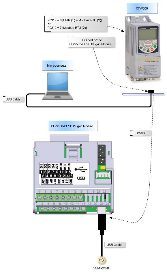
55 bps, no parit y), 8 bits, 2sb SSW7000 USB USBIO CFW-09 PM RS Serial:Address Serial:Bit Rate 311 Serial:Data Con. 312 Serial:Protocol 1: 9600 bps 3: 8b, no parit y, 2sb 2: Modb us- RTU NOTE! Drive and SuperDrive G2 must use the same settings. For CFW-09 PM, P308, P310 and P311 can be changed, see Frequency Inverter Manual - CFW-09 PM. For CFW700, P0308, P0310 and P0311 can be changed, see Programming and Maintenance Manual - CFW700. For SSW, P308 and P312 can be changed, see Serial Communication Manual. (1) CFW500 - Port 1 - terminals 12, 14, 16. (2) CFW500 - Port 2 - USB, DB9 or RS485 connector (terminals 20, 22, 24). 5.2 Connecting the Drive (USB) The drive should be located at a distance shorter than 3 m from the computer. This connection is made with USB Cable, supplied with drive user's guide. USB Driver: user must install the USB driver available at USB_Driver\USBIO folder. CFW-11 Figure below shows how to connect a computer to the drive (USB).

56 WARNING! Switch off the drive before making the connections. 1. The USB connector is in the front cover of the drive. 2. Connect the type B connector of usb cable to the usb connector of the drive. 3. Connect the type A connector of usb cable to the computer usb port. 4. Check if in the SuperDrive G2 Communication Setup the selected connection type is USB. CTW900 WARNING! Switch off the drive before making the connections. 1. The USB connector is in the front cover of the drive. 2. Connect the type B connector of usb cable to the usb connector of the drive. 3. Connect the type A connector of usb cable to the computer usb port. 4. Check if in the SuperDrive G2 Communication Setup the selected connection type is USB. SCA06 WARNING! Switch off the drive before making the connections. 1. The USB connector is in the front cover of the drive. 2. Connect the type B connector of usb cable to the usb connector of the drive. 3. Connect the type A connector of usb cable to the computer usb port. 4. Check if in the SuperDrive G2 Communication Setup the selected connection type is USB. SSW7000 WARNING! Switch off the drive before making the connections. 1. The USB connector is in the front cover of the drive. 2. Connect the type B connector of usb cable to the usb connector of the drive. 3. Connect the type A connector of usb cable to the computer usb port. 4. Check if in the SuperDrive G2 Communication Setup the selected connection type is USB.
57 5.3 Connecting the Drive (USB - Virtual COM Port) The drive should be located at a distance shorter than 3 m from the computer. This connection is made with USB Cable, supplied with drive user's guide. USB Driver: user must install the USB driver available at USB_Driver\FTDI folder. SSW-06 Figure below shows how to connect a computer to the drive (USB).

58 Device manager in Windows indicates which serial port is connected to the drive.
59 The computer name in device manager is purposely unreadable. In SuperDrive G2, select the serial port correctly in Communication Setup window as follows.

60 WARNING! Switch off the drive before making the connections. 1. Connect the mini-b connector of usb cable to the usb connector of the drive. 2. Connect the type A connector of usb cable to the computer usb port. 3. In device manager check which serial port is connected. 4. Check if in the SuperDrive G2 Communication Setup the selected connection type is serial. 5. The serial port in the window of communication setup window should be the same serial port that appears in the device manager, where the USB cable is connected. CFW500 Figure below shows how to connect a computer to the drive (USB).
61
62 Device manager in Windows indicates which serial port is connected to the drive. The computer name in device manager is purposely unreadable. In SuperDrive G2, select the serial port correctly in Communication Setup window as follows.
63 WARNING! Switch off the drive before making the connections. 1. Connect the mini-b connector of usb cable to the usb connector of the drive. 2. Connect the type A connector of usb cable to the computer usb port. 3. In device manager check which serial port is connected. 4. Check if in the SuperDrive G2 Communication Setup the selected connection type is serial. 5. The serial port in the window of communication setup window should be the same serial port that appears in the device manager, where the USB cable is connected. CFW100 Figure below shows how to connect a computer to the drive (USB).
64 Device manager in Windows indicates which serial port is connected to the drive. The computer name in device manager is purposely unreadable.
65 In SuperDrive G2, select the serial port correctly in Communication Setup window as follows.
66 WARNING! Switch off the drive before making the connections. 1. Connect the mini-b connector of usb cable to the usb connector of the drive. 2. Connect the type A connector of usb cable to the computer usb port. 3. In device manager check which serial port is connected. 4. Check if in the SuperDrive G2 Communication Setup the selected connection type is serial. 5. The serial port in the window of communication setup window should be the same serial port that appears in the device manager, where the USB cable is connected. MW500 Figure below shows how to connect a computer to the drive (USB). WARNING! With the drive turned off, be sure that position 1 of DipSwitch S10 is OFF, as shown below:

67
68 Device manager in Windows indicates which serial port is connected to the drive. The computer name in device manager is purposely unreadable. In SuperDrive G2, select the serial port correctly in Communication Setup window as follows.
69 WARNING! Switch off the drive before making the connections. 1. Connect the mini-b connector of usb cable to the usb connector of the drive. 2. Connect the type A connector of usb cable to the computer usb port. 3. In device manager check which serial port is connected. 4. Check if in the SuperDrive G2 Communication Setup the selected connection type is serial. 5. The serial port in the window of communication setup window should be the same serial port that appears in the device manager, where the USB cable is connected. 5.4 Connecting the Drive (RS232) The drive should be located at a distance shorter than 10 m from the computer. SSW-06 Figure below shows how to connect a computer to the drive (RS232 point-to-point).

. WARNING!")
70 WARNING! Switch off the drive before making the connections. 1. Opens the front cover of the drive. 2. Connect the RS232 PC/Drive Serial Cable to the X2 serial connector. 3. Plug DB9 connector directly into any one of the computer serial COM port. Use one of the available serial ports, since this information will be necessary later on SuperDrive G2 Communication Setup during operation. 4. Configure the communication parameters on the drive. The communication parameters are described in Drive Parametrization. SSW-07 Figure below shows how to connect a computer to the drive (RS232 point-to-point). WARNING! Switch off the drive before making the connections. 1. Take out the optional plug-in cover. 2. Replace the cover with the optional plug-in module. Make sure that the module is connected. 3. Insert the DB9 connector of the RS232 Connection Cable to the optional module (XC41 connector) and tighten the screws to fix the connector. 4. Plug DB9 connector directly into any one of the computer serial COM port. Use one of the available serial ports, since this information will be necessary later on the SuperDrive G2 Communication Setup during operation.
71 5. Configure the communication parameters on the drive. The communication parameters are described in Drive Parametrization. SSW-08 WARNING! Switch off the drive before making the connections. 1. Take out the optional plug-in cover. 2. Replace the cover with the optional plug-in module. Make sure that the module is connected. 3. Insert the DB9 connector of the RS232 Connection Cable to the optional module (XC41 connector) and tighten the screws to fix the connector. 4. Plug DB9 connector directly into any one of the computer serial COM port. Use one of the available serial ports, since this information will be necessary later on the SuperDrive G2 Communication Setup during operation. 5. Configure the communication parameters on the drive. The communication parameters are described in Drive Parametrization. MW500 WARNING! Switch off the drive before making the connections. 1. Be sure that accessory RS232 Serial Interface Module is present and correctly connected to the drive. 2. Connect the DB9 connector from RS232 Connection Cable to the DB9 serial connector of RS232 Serial Interface Module. 3. Plug the another DB9 connector of cable directly into any one of the computer serial COM port. Use one of the available serial ports, since this information will be necessary later on the SuperDrive G2 Communication Setup during operation. 4. Configure the communication parameters on the drive. The communication parameters are described in Drive Parametrization. CFW-09 PM WARNING! Switch off the drive before making the connections. 1. Remove the keypad (HMI) from the inverter. 2. Install RS232 Serial Interface Module in place of the keypad. 3. Connect the RS232 PC/Drive Serial Cable to the XC7 serial connector. 4. Plug DB9 connector directly into any one of the computer serial COM port. Use one of the available serial ports, since this information will be necessary later on the SuperDrive G2 Communication Setup during operation. 5. Configure the communication parameters on the drive. The communication parameters are described in Drive Parametrization. 5.5 Connecting the Drive (RS485) The drive should be located at a distance shorter than 1000 m from the computer. CFW700 / CFW701
72 Figure below shows how to connect a computer to the drive (RS485 point-to-point).

73
74 Device manager in Windows indicates which serial port is connected to the USB RS485 converter. The computer name in device manager is purposely unreadable. In SuperDrive G2, select the serial port correctly in Communication Setup window as follows.
75 WARNING! Switch off the drive before making the connections. 1. Connect the type B connector of USB cable to the USB connector of the USB RS485 converter. 2. Connect the type A connector of USB cable to the computer usb port. 3. In device manager check which serial port is connected. 4. Check if in the SuperDrive G2 Communication Setup the selected connection type is serial. 5. The serial port in the window of communication setup window should be the same serial port that appears in the device manager, where the USB cable is connected. CFW500 Figure below shows how to connect a computer to the drive (RS485 point-to-point).

76
77 Device manager in Windows indicates which serial port is connected to the USB RS485 converter. The computer name in device manager is purposely unreadable. In SuperDrive G2, select the serial port correctly in Communication Setup window as follows.
78 WARNING! Switch off the drive before making the connections. 1. Connect the type B connector of USB cable to the USB connector of the USB RS485 converter. 2. Connect the type A connector of USB cable to the computer USB port. 3. In device manager check which serial port is connected. 4. Check if in the SuperDrive G2 Communication Setup the selected connection type is serial. 5. The serial port in the window of communication setup window should be the same serial port that appears in the device manager, where the USB cable is connected. CFW100 Figure below shows how to connect a computer to the drive (RS485 point-to-point).

79 Device manager in Windows indicates which serial port is connected to the USB RS485 converter. The computer name in device manager is purposely unreadable.
80 In SuperDrive G2, select the serial port correctly in Communication Setup window as follows.
81 WARNING! Switch off the drive before making the connections. 1. Connect the type B connector of USB cable to the USB connector of the USB RS485 converter. 2. Connect the type A connector of USB cable to the computer USB port. 3. In device manager check which serial port is connected. 4. Check if in the SuperDrive G2 Communication Setup the selected connection type is serial. 5. The serial port in the window of communication setup window should be the same serial port that appears in the device manager, where the USB cable is connected. MW500 Figure below shows how to connect a computer to the drive (RS485 point-to-point).

82 Device manager in Windows indicates which serial port is connected to the USB RS485
83 converter. The computer name in device manager is purposely unreadable. In SuperDrive G2, select the serial port correctly in Communication Setup window as follows.
84 WARNING! Switch off the drive before making the connections. 1. Connect the type B connector of USB cable to the USB connector of the USB RS485 converter. 2. Connect the type A connector of USB cable to the computer USB port. 3. In device manager check which serial port is connected. 4. Check if in the SuperDrive G2 Communication Setup the selected connection type is serial. 5. The serial port in the window of communication setup window should be the same serial port that appears in the device manager, where the USB cable is connected. ECW500 Figure below shows how to connect a computer to the drive (RS485 point-to-point).

85

86 Device manager in Windows indicates which serial port is connected to the USB RS485 converter. The computer name in device manager is purposely unreadable. In SuperDrive G2, select the serial port correctly in Communication Setup window as follows.
87 WARNING! Switch off the drive before making the connections. 1. Connect the type B connector of USB cable to the USB connector of the USB RS485 converter. 2. Connect the type A connector of USB cable to the computer USB port. 3. In device manager check which serial port is connected. 4. Check if in the SuperDrive G2 Communication Setup the selected connection type is serial. 5. The serial port in the window of communication setup window should be the same serial port that appears in the device manager, where the USB cable is connected. 5.6 Connecting the Drive (Bluetooth) Bluetooth is a wireless technology standard for exchanging data over short distances. The drive must be placed less than 3ft, 33ft or 330ft from computer, depending on Bluetooth class available in the computer. Class Alcance Class 1 Until 330 ft (100 m) Class 2 Until 33 ft (10 m) Class 3 Until 3 ft (1 m) CFW100 The image below shows how to connect a computer to the drive via Bluetooth.

88 1) Drive with CFW100-CBLT accessory. Be sure the drive has a Bluetooth communication module named CFW100-CBLT. Be sure the drive has parameters P310, P311 and P312 set with the factory default values. If the computer does not have Bluetooth technology, use an Bluetooth USB adapter. NOTE! Once USB Bluetooth adapter was enabled in computer, it can not be removed or replaced during its utilization. 2) Be sure that Bluetooth communication module has the red LED (ACTIVE) on. This indicates that it is ready to accept a connection. 3) Be sure that Bluetooth technology is enabled and ready on computer. Bluetooth's logo
 Select the connection type")

89 appears on Windows taskbar. 4) Select the connection type (Bluetooth) in Communication Setup window. 5) Click Scan Equipment button.

90 6) Wait for the scanning of drive. This process takes a few minutes depending on the Bluetooth technology.
91 If there is no error until this step, proceed to item 7. Errors If a problem occurs during this step, please verify the items below: If Bluetooth technology fails during the scanning process, a message is shown. Click OK button and repeat the steps since item 2. Example of failure during detection of Bluetooth technology:

92 If Bluetooth technology was removed or disabled in computer during the scanning process, a message is shown. Example of failure during detection of Bluetooth technology:
93 To fix this problem: Reconnect USB Bluetooth adapter on computer, if it is disconnected; Click OK button as shown previously; Repeat the steps of identification process from item 2. 7) Wait for the system message indicating that drives were found.
94 8) Bluetooth technology requires pairing before allowing the use of their services. Pairing devices is the establishing of a connection between two Bluetooth devices (in this case, between computer and the drive). a) When only one drive is found, the system automatically makes the pairing.
95 b) When more than one drive is found, click the combo box and select a drive. The code presented in this combo box is the content from P770 parameter of CFW100.

96 Click Pair button to make the pairing. NOTE! Always use unique code (P770 content) for each drive. NOTE! Do not skip this step because the system will not warn if any communication failure occurs.
97 9) This process takes a few minutes depending on the Bluetooth technology.

98 10) Wait for the message indicating that the drive was successfully paired.

99 Click OK button to close this window. Drive is ready for use. Green LED (STATUS) in the drive is on. If there is no error until this step, proceed to item 11. Errors If drive is out of range during the pairing process, the STATUS LED is off in drive and a message is shown. Example of failure during the pairing:
 Drive is correctly connected.")
100 To fix this problem: Check if there are obstacles between the drive and the computer; Check if distance between drive and computer is too long; Check if there is another computer with Bluetooth enabled, which is competing for the same drive connection. Repeat the steps from 5. 11) Drive is correctly connected. ACTIVE and STATUS LEDs are on:
 Proceed with drive identification. See Identify Drive for details.")
101 NOTE! If STATUS LED is off: Check if there are obstacles between the drive and computer; Check if distance is too long between drive and computer; Check if there is another computer around with Bluetooth enabled, which is competing for the same drive connection. 12) Proceed with drive identification. See Identify Drive for details. General Information Depending on the Bluetooth technology available on computer, it may be necessary to confirm pairing during the search for Bluetooth drives. This usually occurs in the first connection between drive and computer. In this case just confirm it if any pairing code is showed, selecting Yes and click Next button.

102 If a pairing code is requested, type "1234" and click Next button. 5.7 RS232 Cable RS232 PC/DRIVE SERIAL CABLE Drive: CFW-09 PM, SSW-06 Figure below shows the cable parts for point-to-point RS232 connection. Only pins 2, 3 and 5 of the DB9 female connector are used. Maximum cable length: 10 meters. RS232 CONNECTION CABLE

103 Drive: SSW-07, SSW-08 Figure below shows the cable parts for point-to-point RS232 connection. Only pins 2, 3 and 5 of the DB9 female connector are used. Maximum cable length: 10 meters. 5.8 USB Cable USB CABLE Drive: CFW-11, SCA06, SSW7000, CTW900 Figure below shows the cable parts for point-to-point USB connection. Figure below shows the connectors. A = Type A connector B = Type B connector Maximum cable length: 3 meters. Always use a standard host/device shielded USB cable. Unshielded cables may lead to communication errors.
104 The USB connection is galvanically isolated from the mains power supply and from other high voltages internal to the inverter. However, the USB connection is not isolated from the Protective Ground (PE). Use an isolated computer for the USB connection or a desktop connected to the same Protective Ground (PE) of the inverter. Purchase Suggestions Manufacturer: Samtec, Inc If you want to buy USB cable directly from Samtec, please see below. Description USB shielded High Speed Cable 2.0 Revision, 1 m, Samtec USB shielded High Speed Cable 2.0 Revision, 2 m, Samtec USB shielded High Speed Cable 2.0 Revision, 3 m, Samtec Item USBC-AM-MB-B-B-S-1 USBC-AM-MB-B-B-S-2 USBC-AM-MB-B-B-S-3 At the time this help was being written, the specification was found at Smartec website. USB CABLE (mini-b) Drive: CFW100 Figure below shows the cable parts for point-to-point USB connection. Figure below shows the connectors.

105 A = Type A connector B = Type mini-b connector Maximum cable length: 3 meters. Always use a standard host/device shielded USB cable. Unshielded cables may lead to communication errors. The USB connection is galvanically isolated from the mains power supply and from other high voltages internal to the inverter. However, the USB connection is not isolated from the Protective Ground (PE). Use an isolated computer for the USB connection or a desktop connected to the same Protective Ground (PE) of the inverter. Purchase Suggestions Manufacturer: Samtec, Inc If you want to buy USB cable directly from Samtec, please see below. Description USB shielded High Speed Cable 2.0 Revision, 1 m, Samtec USB shielded High Speed Cable 2.0 Revision, 2 m, Samtec USB shielded High Speed Cable 2.0 Revision, 3 m, Samtec Item USBC-AM-BM-B-B-S-1 USBC-AM-BM-B-B-S-2 USBC-AM-BM-B-B-S-3 At the time this help was being written, the specification was found at Smartec website. 5.9 USB to Serial Adapter The USB to serial adapter is the best solution for the connection of serial equipment (RS232) to USB ports, i. e., for connecting computer USB output to a RS232 serial equipment. This is a low cost solution and meets the install requirements of new computer serial ports that have busy bus bars or equipments that are not fitted with RS232 ports. The USB to serial adapter allows the plug & play connection with your computer, thus


106 maintaining free the existing serial port. Figures below show a sample of this adapter. PURCHASE SUGGESTIONS Manufacturer: Comm5 Tecnologia Product: Conversor de USB para 1 saída serial RS232 Model: 1S-USB - conversor USB para 1 serial Web Site For further information about product installation, please refer to user's manual. Manufacturer: Tripp Lite Product: USB High Speed Serial Adapter Model: USA-19HS Web Site For further information about product installation, please refer to user's manual.

107 5.10 Bluetooth USB Adapter Drive: CFW100 The image below shows an USB Bluetooth adapter (a.k.a. dongle) which should be connected to the USB port of computer. There are several models with different features Before Trying to Establish Communication Before trying to establish communication make sure the following has been done: Communication cable connected to the drive; Communication cable connected to computer; Drive is powered up; Communication parameters on the drive correspond to SuperDrive G2 communication settings Exception During Monitoring SOFT-STARTER SSW-06 V1.3X P014 to P017 = => this means there is no fault. SSW-07 and SSW-08 P219 defines parametrization mode for the following parameters: P101, P102, P104, P110, P202, P206, P401, P520, P521, P611, P613, P617, P620 and P640; On Trimpot and Dip Switch Mode, the parametrization of the above parameters is done through the Trimpots and Dip Switches. These parameters act like read only parameters, showing the Trimpots and Dip Switches programmed values. The values which where programmed through RS232 serial communication are not used; On Keypad Mode, the parametrization of parameters previously cited is made with RS232 serial communication or Keypad. The value adjusted with Trimpots and Dip Switch are not used.
DriveWizard Plus Instruction Manual
 DriveWizard Plus Instruction Manual To properly use the product, read this manual thoroughly. MANUAL NO. TOEP C730600 20C Table of Contents Safety Symbols and Markings...4 Manual Overview...5 Related Manuals...5
TROVIS-VIEW 4 Software TROVIS Operating Instructions EB 6661 EN. Electronics from SAMSON
 TROVIS-VIEW 4 Software TROVIS 6661 Operating Instructions Electronics from SAMSON EB 6661 EN Edition January 2015 Definition of signal words DANGER! Hazardous situations which, if not avoided, will result
TROVIS-VIEW 4 Software TROVIS Operating Instructions EB 6661 EN. Electronics from SAMSON
 TROVIS-VIEW 4 Software TROVIS 6661 Operating Instructions Electronics from SAMSON EB 6661 EN Edition August 2017 Definition of signal words DANGER! Hazardous situations which, if not avoided, will result
Spectrometer Visible Light Spectrometer V4.4
 Visible Light Spectrometer V4.4 Table of Contents Package Contents...3 Trademarks...4 Manual Driver and Application installation...5 Manual Application Installation...6 First Start of the Application...8
Magnetek Material Handling IMPULSE LINK 4.1 Basic Instruction Manual
 Magnetek Material Handling IMPULSE LINK 4.1 Basic Instruction Manual February 2006 Part Number: 140-10350 Copyright 2006 Magnetek Material Handling 2005 MAGNETEK MATERIAL HANDLING All rights reserved.
User Guide 701P Wide Format Solution Wide Format Scan Service
 User Guide 701P44865 6204 Wide Format Solution Wide Format Scan Service Xerox Corporation Global Knowledge & Language Services 800 Phillips Road Bldg. 845-17S Webster, NY 14580 Copyright 2006 Xerox Corporation.
Motors Automation Energy Transmission & Distribution Coatings. Software. SuperDrive User's Manual
 Motors Automation Energy Transmission & Distribution Coatings Software SuperDrive 6.10 User's Manual User's Manual Series: SuperDrive Language: English Document: 10001830633 Publication Date: 07/31/2012
Navigator Software User s Manual. User Manual. Navigator Software. Monarch Instrument Rev 0.98 May Page 1 of 17
 User Manual Navigator Software Monarch Instrument Rev 0.98 May 2006 Page 1 of 17 Contents 1. NAVIGATOR SOFTWARE 2. INSTALLATION 3. USING NAVIGATOR SOFTWARE 3.1 STARTING THE PROGRAM 3.2 SYSTEM SET UP 3.3
Engineering Tool for PC SDWP001 Operating Manual
 Inverter HF-520/HF-X20 Series SF-520 Series Engineering Tool for PC SDWP001 Operating Manual 1 Manual No. DM2308E-1 Table of Contents Safety Symbols and Markings...4 Safety Notes and Instructions...4 Manual
WebPakCS Software Version 1.0
 WebPakCS Software Version 1.0 Instruction Manual D2-3447 The information in this manual is subject to change without notice. Throughout this manual, the following notes are used to alert you to safety
DriveWare. User s Guide DriveBrowser
 DriveWare User s Guide DriveBrowser DriveBrowser User s Guide Code: 3AUA0000024806 EN EFFECTIVE: 31.12.2008 SUPERCEDES 31.01.2008 2008 ABB Oy. All rights reserved. 5 Table of contents Table of contents...
User Manual. MPPTracker. Management Software for Solar Charge Controller. Version: 1.2
 User Manual MPPTracker Management Software for Solar Charge Controller Version: 1.2 Table of Contents 1. MPPTracker Overview... 1 1.1. Introduction... 1 1.2. Features... 1 2. MPPTracker Install and Uninstall...
DriveView v3.0 User s Manual
 DriveView v3.0 User s Manual Driveview 3.0 is a Windows based drive commissioning tool that allows direct control, monitoring and setup of all parameters of LSIS s AC drives. It s function is to make commissioning
SolarPower Pro. User s Manual. Management Software for Solar Inverter
 SolarPower Pro User s Manual Management Software for Solar Inverter Table of Contents 1. SolarPower Pro Overview... 2 1.1. Introduction... 2 1.2. Structure... 2 1.3. Features... 3 2. SolarPower Pro Install
AEMLog Users Guide. Version 1.01
 AEMLog Users Guide Version 1.01 INTRODUCTION...2 DOCUMENTATION...2 INSTALLING AEMLOG...4 AEMLOG QUICK REFERENCE...5 THE MAIN GRAPH SCREEN...5 MENU COMMANDS...6 File Menu...6 Graph Menu...7 Analysis Menu...8
Magnetek Material Handling IMPULSE LINK 4.1 Basic Instruction Manual
 Magnetek Material Handling IMPULSE LINK 4.1 Basic Instruction Manual March 2013 Part Number: 140-10350 R6 Copyright 2013 Magnetek Material Handling 2013 MAGNETEK MATERIAL HANDLING All rights reserved.
TouchKit TouchScreen Controller User Manual for Windows NT4 Version: 3.4.0
 TouchKit TouchScreen Controller User Manual for Windows NT4 Version: 3.4.0 1 CONTENT CHAPTER 1. TOUCH PANEL CONTROLLER 2 1.1 Controller 2 1.2 Specifications and Features 3 CHAPTER 2. INSTALLING TOUCHKIT
User Manual WatchPower
 User Manual WatchPower Management Software for SP Efecto / SP Brilliant (Plus) / SP Initial Table of Contents 1. WatchPower Overview...1 1.1. Introduction... 1 1.2. Features... 1 2. WatchPower Install
Windows Me Navigating
 LAB PROCEDURE 11 Windows Me Navigating OBJECTIVES 1. Explore the Start menu. 2. Start an application. 3. Multi-task between applications. 4. Moving folders and files around. 5. Use Control Panel settings.
TouchKit TouchScreen Controller User Guide for Windows NT4 Version: 3.2.1
 TouchKit TouchScreen Controller User Guide for Windows NT4 Version: 3.2.1 TouchKit Guide for WinNT4 v3.2.1 0 CONTENT CHAPTER 1. TOUCH PANEL CONTROLLER... 2 1.1 CONTROLLER... 2 1.2 SPECIFICATIONS AND FEATURES...
GXLink MultiChannel Wave Inserter Model SP-631
 800173-0A Digital High Speed GXLink MultiChannel Wave Inserter Model SP-631 User Manual Copyright 2009 It is prohibited to copy, reproduce or distribute this information in whole or in part without the
MRZJW3- SETUP154E. General-Purpose AC Servo Servo Configuration Software MODEL INSTALLATION GUIDE
 General-Purpose AC Servo Servo Configuration Software MODEL MRZJW3- SETUP154E INSTALLATION GUIDE Thank you for choosing the Mitsubishi general-purpose AC servo Servo Configuration Software. To optimize
Connect Install Guide
 Connect Install Guide Version 3.2 Publication Date: December 16, 2013 Copyright Metalogix International GmbH 2008-2013. All Rights Reserved. This software is protected by copyright law and international
ASIC-200 Version 5.0. integrated industrial control software. HMI Guide
 ASIC-200 Version 5.0 integrated industrial control software HMI Guide Revision Description Date C Name change, correct where applicable with document 4/07 HMI Guide: 139168(C) Published by: Pro-face 750
N2KExtractor. NMEA 2000 Data Extractor Software. User s Manual
 N2KExtractor NMEA 2000 Data Extractor Software User s Manual Revision 1.0.0 Copyright 2012 Maretron, LLP All Rights Reserved Maretron, LLP 9014 N. 23 rd Ave #10 Phoenix, AZ 85021-7850 http://www.maretron.com
ShineNet. Growatt Version Date Notes New. ShineNet V1.0
 ShineNet Growatt 1.0 2012-09-25 Version Date Notes 1.0.0.2 2012-09-25 New Table of Contents 1. Introduction...3 2. Install and Uninstall...4 2.1 System requirements...4 2.2 Install software...4 2.3 Uninstall
Device Programming using TRWinProg
 Device Programming using TRWinProg Software No.: _490-00416 _490-00416_WIN7 _Program Summary _Safety instructions _System requirements _Program installation _Connecting devices to the PC _Program start
Adobe Acrobat Reader 4.05
 Adobe Acrobat Reader 4.05 1. Installing Adobe Acrobat Reader 4.05 If you already have Adobe Acrobat Reader installed on your computer, please ensure that it is version 4.05 and that it is Adobe Acrobat
Aurora Multi-image System Control Software. User Manual
 Aurora Multi-image System Control Software User Manual Product Information Model: Aurora Controller Software Version: V010200 Release Date: January 18th, 2017 Company OSEE TECHNOLOGY CO., LTD. Contact
CulinarE-Companion. Version 4.3 TABLE OF CONTENTS
 CulinarE-Companion Version 4.3 Copyright 2012 by John Wiley & Sons Ltd. All rights reserved. TABLE OF CONTENTS 1. ABOUT THE SOFTWARE 2. SYSTEM REQUIREMENTS 3. INSTALLING AND RUNNING THE PROGRAM 3.1. Installing
Wavy for PAS&PWR Ver. 5.0
 Kikuchi 07 22 08 Operation Manual Sequence Creation Software Kobayashi 07 22 08 Wavy for PAS&PWR Ver. 5.0 Version 5.0 Prepared: July 22, 2008 KIKUSUI ELECTRONICS CORPORATION IB01809 1 1/34 Note Before
Table of Contents. Logos Imaging Application User s Manual Version Page 1
 Table of Contents About... 4 System Requirements... 5 Uninstall Previous Versions... 5 Install LIA 6.0... 6 Install the Device Drivers... 13 Register... 14 Getting Help... 14 Technical Support... 14 Workspace
User Manual WatchPower
 User Manual WatchPower Management Software for Inverter Table of Contents 1. WatchPower Overview... 1 1.1. Introduction... 1 1.2. Features... 1 2. WatchPower Install and Uninstall... 1 2.1. System Requirement...
TouchScreen for Display & Panel-PC
 TouchScreen for Display & PanelPC User Manual for Windows 2000 / XP Version: 4.0.2 TouchKit Manual for Win2000/XP v4.0.2 Page 1 CONTENT CHAPTER 1. TOUCH PANEL CONTROLLER... 3 1.1 CONTROLLER... 3 1.2 SPECIFICATIONS
Beyond 20/20. Browser - English. Version 7.0, SP3
 Beyond 20/20 Browser - English Version 7.0, SP3 Notice of Copyright Beyond 20/20 Desktop Browser Version 7.0, SP3 Copyright 1992-2006 Beyond 20/20 Inc. All rights reserved. This document forms part of
FaxFinder Fax Servers
 FaxFinder Fax Servers Models: FF130 FF230 FF430 FF830 Client User Guide FaxFinder Client User Guide Fax Client Software for FaxFinder Series PN S000460B, Version B Copyright This publication may not be
SOFTWARE USER S GUIDE
 SOFTWARE USER S GUIDE RJ series The contents of this guide and the specifications of this product are subject to change without notice. Brother reserves the right to make changes without notice in the
Getting Started With the Cisco PAM Desktop Software
 CHAPTER 3 Getting Started With the Cisco PAM Desktop Software This chapter describes how to install the Cisco PAM desktop client software, log on to Cisco PAM, and begin configuring access control features
TouchKit TouchScreen Controller User Guide for Windows 2000 / XP Version: 3.2.4
 TouchKit TouchScreen Controller User Guide for Windows 2000 / XP Version: 3.2.4 TouchKit Guide for Win2000/XP v3.2.4 0 CONTENT CHAPTER 1. TOUCH PANEL CONTROLLER...2 1.1 CONTROLLER...2 1.2 SPECIFICATIONS
SEWCAT USER MANUAL V APRIL 14, 2017 S & S COMPUTING Oak Ridge, TN 37830
 SEWCAT USER MANUAL V4.0.6 APRIL 14, 2017 S & S COMPUTING Oak Ridge, TN 37830 Contents 1. Introduction... 3 1.1 Getting Started... 3 1.2 Frequently Asked Questions (FAQ)... 5 1.3 Contact Us... 5 1.4 Purchase
TM Printer Service and Support Utility for Windows Version 2.xx User s Manual (English)
") TM Printer Service and Support Utility for Windows Version 2.xx User s Manual (English) Rev. B Table of Contents Introduction...1 Purpose of This Manual and Target Users... 1 Composition of This Manual...
TM Printer Service and Support Utility for Windows Version 2.xx User s Manual (English) Rev. B Table of Contents Introduction...1 Purpose of This Manual and Target Users... 1 Composition of This Manual...
TouchKit Touch Panel User manual for WindowsNT4 Version: 3.1.4
 TouchKit Touch Panel User manual for WindowsNT4 Version: 3.1.4 TouchKit Touch Panel v3.1.4 0 CONTENT CHAPTER 1. TOUCH PANEL CONTROLLER...2 1.1 CONTROLLER...2 1.2 SPECIFICATIONS AND FEATURES...3 CHAPTER
LE840/LE850. Printer Setting Tool Manual Technical Reference
 LE840/LE850 Printer Setting Tool Manual Technical Reference Table of Contents 1. INTRODUCTION 1 SUPPORTED PRINTERS... 1 FEATURES... 1 OUTLINE OF THE FUNCTIONS... 2 NOTATION... 2 SCREENS USED IN THIS DOCUMENT...
ViewPower. User s Manual. Management Software for Uninterruptible Power Supply Systems
 ViewPower User s Manual Management Software for Uninterruptible Power Supply Systems Table of Contents 1. ViewPower Overview...2 1.1. Introduction...2 1.2. Structure...2 1.3. Applications...2 1.4. Features...3
N2KExtractor. Maretron Data Extraction Software User s Manual
 N2KExtractor Maretron Data Extraction Software User s Manual Revision 3.1.6 Copyright 2017 Maretron, LLP All Rights Reserved Maretron, LLP 9014 N. 23rd Ave #10 Phoenix, AZ 85021-7850 http://www.maretron.com
TouchKit Touch Panel User manual for WindowsNT4 Version: 3.1.4
 TouchKit Touch Panel User manual for WindowsNT4 Version: 3.1.4 TouchKit Touch Panel v3.1.4 0 CONTENT CHAPTER 1. TOUCH PANEL CONTROLLER... 2 1.1 CONTROLLER... 2 1.2 SPECIFICATIONS AND FEATURES... 3 CHAPTER
Workstation Configuration Guide
 Workstation Configuration Guide August 13, 2018 Version 9.6.134.78 For the most recent version of this document, visit our documentation website. Table of Contents 1 Workstation configuration 4 1.1 Considerations
Wavy for PAX Ver. 4.0
 Operation Manual Sequence Creation Software Wavy for PAX Ver. 4.0 SPEC70289 Version 4.0 Prepared: June 21, 2006 KIKUSUI ELECTRONICS CORPORATION 1/34 Contents Note Before contacting us to request repair,
GV 2 Devicemanagement 2
 GV 2 Devicemanagement 2 getting started & usage 1/13 Index 1 General Remarks...3 2 Software...3 2.1 System Requirements...3 2.2 Installation...4 2.3 Un-Installation...5 3 User Interface...5 3.1 Menu Bar...6
Wavy for PLZ-4W Ver. 4.0
 Operation Manual Sequence Creation Software Wavy for PLZ-4W Ver. 4.0 Version 4.0 Prepared: June 21, 2006 KIKUSUI ELECTRONICS CORPORATION 1/35 Note Before contacting us to request repair, inspection, or
VANGUARD LOAD TAP CHANGER ANALYZER (LTCA) VERSION 2.xx SOFTWARE MANUAL. LTCA-10, LTCA-40, WRM-10P, WRM-40, TRM-20, TRM-40, TRM-203, and TRM-403
 VERSION 2.xx SOFTWARE MANUAL. LTCA-10, LTCA-40, WRM-10P, WRM-40, TRM-20, TRM-40, TRM-203, and TRM-403") VANGUARD LOAD TAP CHANGER ANALYZER (LTCA) VERSION 2.xx SOFTWARE MANUAL For Use with Vanguard s LTCA-10, LTCA-40, WRM-10P, WRM-40, TRM-20, TRM-40, TRM-203, and TRM-403 Load Tap Changer Analyzers and Winding
VANGUARD LOAD TAP CHANGER ANALYZER (LTCA) VERSION 2.xx SOFTWARE MANUAL For Use with Vanguard s LTCA-10, LTCA-40, WRM-10P, WRM-40, TRM-20, TRM-40, TRM-203, and TRM-403 Load Tap Changer Analyzers and Winding
TouchKit Touch Panel User manual for Windows9X/ME Version: 3.1.4
 TouchKit Touch Panel User manual for Windows9X/ME Version: 3.1.4 TouchKit Touch Panel v3.1.4 0 CONTENT CHAPTER 1. TOUCH PANEL CONTROLLER... 2 1.1 CONTROLLER... 2 1.2 SPECIFICATIONS AND FEATURES... 3 CHAPTER
Thermal Transient Test Installation and Operating Manual
 Thermal Transient Test Installation and Operating Manual 2705A De La Vina Street Santa Barbara, California 93105 Telephone (805) 682-0900 descon@silcom.com www. santabarbaraautomation.com Installation
NETWORK PRINT MONITOR User Guide
 NETWORK PRINT MONITOR User Guide Legal Notes Unauthorized reproduction of all or part of this guide is prohibited. The information in this guide is subject to change for improvement without notice. We
Architect. User s Manual
 Architect User s Manual DOC. NO. UM-PT202-03 Version 1.11 January 2013 TABLE OF CONTENTS Chapter 1: Introduction...1 Features... 1 System Requirements... 2 Installing the Software... 2 Opening the Software...
Thermo Scientific. GRAMS Envision. Version 2.1. User Guide
 Thermo Scientific GRAMS Envision Version 2.1 User Guide 2013 Thermo Fisher Scientific Inc. All rights reserved. Thermo Fisher Scientific Inc. provides this document to its customers with a product purchase
Legal Notes. Regarding Trademarks KYOCERA MITA Corporation
 Legal Notes Unauthorized reproduction of all or part of this guide is prohibited. The information in this guide is subject to change without notice. We cannot be held liable for any problems arising from
FTRESTORE. Yaesu FT Radio Configuration Restore Utility
 FTRESTORE Yaesu FT Radio Configuration Restore Utility VK2BYI FTRestore is a Windows desktop application designed to upload, download and compare memory channels and menu settings in the Yaesu FTDX1200
Network Management Software ALLNET Zone Controller
 Network Management Software ALLNET Zone Controller For ALL0558N / ALL02850N / ALL02860ND / ALL02880ND User Manual v1.0 Table of Contents 1. Installation & Un-installation... 4 1.1. Install NMS Suite...
AEMLog users guide V User Guide - Advanced Engine Management 2205 West 126 th st Hawthorne CA,
 AEMLog users guide V 1.00 User Guide - Advanced Engine Management 2205 West 126 th st Hawthorne CA, 90250 310-484-2322 INTRODUCTION...2 DOCUMENTATION...2 INSTALLING AEMLOG...4 TRANSFERRING DATA TO AND
MW100 CAN Bus Module Configuration Tool (MX118-CAN-M30/S1) User s Manual
 User s Manual") MW100 CAN Bus Module Configuration Tool (MX118-CAN-M30/S1) User s Manual 1 Contents Before Using the Software... 3 Explanation of Functions... 3 MX118 Part Names and Functions... 3 Operation Guide... 4
MW100 CAN Bus Module Configuration Tool (MX118-CAN-M30/S1) User s Manual 1 Contents Before Using the Software... 3 Explanation of Functions... 3 MX118 Part Names and Functions... 3 Operation Guide... 4
Acrobat X Professional
 Acrobat X Professional Toolbar Well Page Navigations/Page Indicator Buttons for paging through document Scroll Bar/box page indicator appears when using the scroll button to navigate. When you release
Creating Interactive PDF Forms
 Creating Interactive PDF Forms Using Adobe Acrobat X Pro for the Mac University Information Technology Services Training, Outreach, Learning Technologies and Video Production Copyright 2012 KSU Department
W-E
 Signage Suite V2.20 User Guide 605220-02-01-W-E-051613-02 Trademarks Windows XP, Windows Vista, Windows 7, and Microsoft are registered trademarks of Microsoft Corporation. All other trademarks are the
AMD RAID Installation Guide
 AMD RAID Installation Guide 1. AMD BIOS RAID Installation Guide.. 3 1.1 Introduction to RAID.. 3 1.2 RAID Configurations Precautions 4 1.3 Installing Windows 8 / 8 64-bit / 7 / 7 64-bit / Vista / Vista
FRENIC Visual Customizer
 Instruction Manual Inverter Support Software FRENIC Visual Customizer for FRENIC-Ace series Thank you for purchasing our high-performance, multipurpose FRENIC-Ace Series inverter. This manual provides
Starter Kit Manual. Table of Contents
 Starter Kit Manual Table of Contents Chapter 1 Introduction of UT Series Starter Kits 1.1 General Information about UT Series Starter Kits... 1-2 1.1.1 Components of UT Series Starter Kits... 1-2 1.2 System
Wavy for PLZ-4W Ver. 5.3
 T.Shimbo 14 8 6 Operation Manual Sequence Creation Software Y.Oyama 14 8 6 Wavy for PLZ-4W Ver. 5.3 Version 5.3 Prepared: August, 2014 KIKUSUI ELECTRONICS CORPORATION 1/38 Note Before contacting us to
14 July Ver CRView V3 User Guide. 1 P a g e
 Ver. 080707 CRView V3 User Guide 1 P a g e Contents Copyright notice... 3 Trademarks... 3 System requirements... 4 Required hardware... 4 Recommended hardware... 4 Installing CRView... 5 Installing from
TPEditor User Manual
 Table of Contents TPEditor User Manual Chapter 1 TPEditor Operation... 1-1 1-1 Recommended System Requirements... 1-1 1-2 TPEditor Software Installation... 1-1 1-3 Basic Introduction... 1-6 1-4 Skills
Rev T 237
 9424200996 Rev T 237 BESTCOMSPlus is a Windows -based, PC application that provides a user-friendly, graphical user interface (GUI) for use with Basler Electric communicating products. The name BESTCOMSPlus
FactoryLink 7. Version 7.0. Client Builder Reference Manual
 FactoryLink 7 Version 7.0 Client Builder Reference Manual Copyright 2000 United States Data Corporation. All rights reserved. NOTICE: The information contained in this document (and other media provided
INST.NO. INE-919. DI5000 Setting Software
 INST.NO. INE919 DI5000 Setting Software Table of contents 1. Introduction... 1 2. System Requirement... 3 21 Operation Condition of the Software... 3 3 How to Setup... 4 31. Installation... 4 311. New
Chapter 2 Autodesk Asset Locator... 3
 Contents Chapter 2 Autodesk Asset Locator....................... 3 Supported Operating Systems....................... 3 Installing Autodesk Asset Locator..................... 4 Define a Search...............................
StrikeRisk v5.0 Getting started
 StrikeRisk v5.0 Getting started Contents 1 Introduction 1 2 Installing StrikeRisk 2 7 2.1 System Requirements 2 2.2 Installing StrikeRisk 2 5 2.3 Installation troubleshooting 6 2.4 Uninstalling StrikeRisk
Cascade Configuration Tool
 Cascade Configuration Tool Version 1.0.10 Installation and Operations Manual 00-02-0724 01-25-11 Section 40 In order to consistently bring you the highest quality, full featured products, we reserve the
User Manual PDUTracker
 User Manual PDUTracker Management Software for PDU Table of Contents 1. Overview... 1 1.1. Introduction... 1 1.2. Features... 1 2. Install and Uninstall... 1 2.1. System Requirement... 1 2.2. Software
Workstation Configuration
 Workstation Configuration December 12, 2017 - Version 9.4 - - - - - - - - - - - - - - - - - - - - - - - - - - - - - - - - - - - - - - - - - - - - - - - - - - - - - - - - - - - - - - - - - - - - - - - -
JANOME ELECTRO PRESS. Operation Manual. <PC Operation>
 JANOME ELECTRO PRESS JP-104 JP-204 JP-504 JP-1004 JP-1504 JP-3004 JP-5004 JPH-104 JPH-204 JPH-504 JPH-1004 JPH-1504 JPH-3004 JPH-5004 JPU-104 JPU-204 JPU-504 JPU-1004 JPU-1504 JPU-3004 JPU-5004 JPU-8004
Software Manual R Index 1
 Software Manual R60727.0002 - Index 1 OS6.0 Operator software for Kübler devices Product features: For PCs and notebooks with Windows 7 or higher Easy parametrization, configuration and monitoring Additional
GL500A Application Manual
 GL500A Application Manual Main Functions A Variety of Waveform Displays Y-T, X-Y, and FFT waveforms can be displayed on large, easy-to-read screens. Dual-screen Event and Current Data Replay Current data
Central Management Software. Cam Viewer 3 Lite. User Manual
 Central Management Software Cam Viewer 3 Lite User Manual Version 1.0.0 Table of Contents 1. System Requirement...4 2. Software Installation...5 3. Configuration Wizard...9 3.1 Channel...10 3.1.1 Adding
User Manual MPPTracker
 User Manual MPPTracker Management Software for Solar Charge Controller Version: 1.0 Table of Contents 1. MPPTracker Overview... 1 1.1. Introduction... 1 1.2. Features... 1 2. MPPTracker Install and Uninstall...
Wavy for PAT-T Ver. 5.2
 T.Shimbo 15 6 26 Operation Manual Sequence Creation Software Watanabe 15 6 26 Wavy for PAT-T Ver. 5.2 Version 5.2 Prepared: June, 2015 KIKUSUI ELECTRONICS CORPORATION IB01981 3 1/34 Note Before contacting
ARES. User s Guide. Aprilia Racing Engine Setup. English version
 ARES Aprilia Racing Engine Setup User s Guide English version ARES user s guide 2/59 I. WARNINGS... 6 II. SOFTWARE AND ENGINE CONFIGURATION COMPATIBILITY... 6 III. BEFORE UPDATING ARES TO A NEWER VERSION...
Greyline Logger. Greyline Logger
 Contents Index Greyline Logger Menu Commands File Edit View Data Logging Communication Connection Setup... Remote Modems Export Graph... Text/Data Only Export ToolBar and Buttons Hotkeys & Shortcuts Summary
Instruction Manual HIOKI Standby Power Measurement Software
 Instruction Manual HIOKI Standby Power Measurement Software This manual explains the free software (HIOKI Standby Power Measurement Software) for the HIOKI Power Meter series only. Please refer to the
User Manual SolarTracker
 User Manual SolarTracker Management Software for Inverter Table of Contents 1. SolarTracker Overview... 1 1.1. Introduction... 1 1.2. Features... 1 2. SolarTracker Install and Uninstall... 1 2.1. System
Data setting software MEXE02
 HM-40143 Data setting software MEXE02 OPERATING MANUAL Before Use Thank you for purchasing an Oriental Motor product. This operating manual describes product handling procedures and safety precautions.
WINDOWS NT BASICS
 WINDOWS NT BASICS 9.30.99 Windows NT Basics ABOUT UNIVERSITY TECHNOLOGY TRAINING CENTER The University Technology Training Center (UTTC) provides computer training services with a focus on helping University
SIMATIC HMI. StoragePlus V1.3 SP1 / PCS 7 V7.1 MDM - Storage Plus Information System. StoragePlus Installation Instructions 1. StoragePlus Readme 2
 StoragePlus Installation Instructions 1 StoragePlus Readme 2 SIMATIC HMI StoragePlus V1.3 SP1 / PCS 7 V7.1 MDM - Storage Plus Information System StoragePlus Administration Console 3 StoragePlus View Editor
FileMaker. Mobile 7. User s Guide. For Windows, Mac, Palm OS, and Pocket PC. Companion for Palm OS and Pocket PC
 For Windows, Mac, Palm OS, and Pocket PC FileMaker Mobile 7 Companion for Palm OS and Pocket PC User s Guide 2000-2004 FileMaker, Inc. All Rights Reserved. FileMaker, Inc. 5201 Patrick Henry Drive Santa
SICAM SICAM FCM Configurator
 Preface Open Source Software SICAM SICAM FCM Configurator Table of Contents SICAM FCM Configurator 1 Index V02.10 Configuration and Operation E50417-H8940-C592-A3 i NOTE For your own safety, observe the
User s Manual. Touch Panel Driver. Important
 User s Manual Touch Panel Driver Important Please read the Precautions and this User s Manual carefully to familiarize yourself with safe and effective usage. The software described in this document is
KMnet Viewer. User Guide
 KMnet Viewer User Guide Legal Notes Unauthorized reproduction of all or part of this guide is prohibited. The information in this guide is subject to change for improvement without notice. We cannot be
MagicInfo VideoWall Author
 MagicInfo VideoWall Author MagicInfo VideoWall Author User Guide MagicInfo VideoWall Author is a program designed to construct a VideoWall layout and create VideoWall content by adding various elements
TouchScreen Controller User Manual
 TouchScreen Controller User Manual for Windows 9X / ME Version: 3.4.0 Customer : Model : 32-4W232/4WUSB/5W232/5WUSB-BB Date : Version: Acceptance Sheet Onetouch Technologies Co., Ltd. (Supplier) (Purchaser)
User s Guide. For Windows, Mac, Palm OS, and Pocket PC. Companion for Palm OS and Pocket PC
 For Windows, Mac, Palm OS, and Pocket PC FileMMobile aker8 Companion for Palm OS and Pocket PC User s Guide 2000-2006 FileMaker, Inc. All Rights Reserved. FileMaker, Inc. 5201 Patrick Henry Drive Santa
CyberComm Pro Data Acquisition Software Installation & User Guide
 CyberComm Pro 2.2.3 Data Acquisition Software Installation & User Guide ph 1100 and ph 2100 Bench ph and Bench ph/ion Meter Technology Made Easy... 68X090822 rev 1 Aug 2002 2 PREFACE Thank you for selecting
Installing TAM Air Assistant Software TM
 Installing TAM Air Assistant Software TM Installation Instructions This document describes how to make a new installation of TAM Air Assistant. TAM Air Assistant is intended to be installed on a PC running