CU USB-Extender-Rx (USB and DVI Extender) Version: 0.3 Date:
|
|
|
- Cleopatra Simpson
- 5 years ago
- Views:
Transcription
1 CU USB-Extender-Rx (USB and DVI Extender) Version: 0.3 Date:
2 Table of Contents Table of Contents 1 Foreword Notes on the documentation Liability Conditions Conditions of delivery Copyright Safety Instructions State at Delivery Description of safety symbols 2 2 Product Overview Introduction Technical Data Dimensions 5 3 Installation Installing USB-cable strain relief Mounting / Unmounting Mounting on a planar surface Mounting on a 35 mm C mounting rail Power Supply UL requirements Data - Connectors LED Diagnostics Architecture Description 12 4 Approvals for USA and Canada FCC Approval for USA FCC Approval for Canada 14 5 Appendix BECKHOFF support and service BECKHOFF support BECKHOFF service BECKHOFF headquarters 15 CU
3 Foreword 1 Foreword 1.1 Notes on the documentation This description is only intended for the use of trained specialists in control and automation engineering who are familiar with the applicable national standards. It is essential that the following notes and explanations are followed when installing and commissioning these components Liability Conditions The responsible staff must ensure that the application or use of the products described satisfy all the requirements for safety, including all the relevant laws, regulations, guidelines and standards. The documentation has been prepared with care. The products described are, however, constantly under development. For that reason the documentation is not in every case checked for consistency with performance data, standards or other characteristics. None of the statements of this manual represents a guarantee (Garantie) in the meaning of 443 BGB of the German Civil Code or a statement about the contractually expected fitness for a particular purpose in the meaning of 434 par. 1 sentence 1 BGB. In the event that it contains technical or editorial errors, we retain the right to make alterations at any time and without warning. No claims for the modification of products that have already been supplied may be made on the basis of the data, diagrams and descriptions in this documentation Conditions of delivery Furthermore the general conditions of delivery of company Beckhoff Automation GmbH apply Copyright This documentation is copyrighted. Any reproduction or third party use of this publication, whether in whole or in part, without the written permission of Beckhoff Automation GmbH, is forbidden. CU
4 Foreword 1.2 Safety Instructions State at Delivery All the components are supplied in particular hardware and software configurations appropriate for the application. Modifications to hardware or software configurations other than those described in the documentation are not permitted, and nullify the liability of Beckhoff Automation GmbH Description of safety symbols The following safety symbols are used in this operating manual. They are intended to alert the reader to the associated safety instructions. Danger This symbol is intended to highlight risks for the life or health of personnel. Warning This symbol is intended to highlight risks for equipment, materials or the environment. Note This symbol indicates information that contributes to better understanding. CU
5 Product Overview 2 Product Overview 2.1 Introduction The Beckhoff USB-Extender-Rx allows to extend the limits of USB cable length. Standard USB cable are specified for cable length up to 5 meters. For some industrial applications there is need for longer distances. This box can extend the distance up to 50 meters. This box receive the externded USB signals from sending box CU8800 and convert them back to USB. It also conditions the DVI video signals. Other outstanding features are: User-friendly installation via mounting kit Optional installation via top hat rail adapter 24 V DC supply voltage the standard in industrial evironments 12 Mbit, and 1,5 Mbit support for compatibility to all USB1.1 standards Standard CAT5 network cable for extension compact industrial design clear quick diagnosis by separate LEDs for USB and DVI conditions CU
6 Product Overview 2.2 Technical Data Product name CU Number of USB type A ports (downstream) 1 Number of USB Extender-Rx ports (RJ45) 1 Number of DVI Input ports 1 Number of DVI Output ports 1 Supported standard DVI, USB 1.1 Supported baud rates USB 12 Mbit (Full Speed), 1,5 Mbit (Low Speed) Supported Modes DVI 640 x 60 Hz, 800 x 60 Hz, 1024 x 60 Hz, 1280 x 60 Hz Status display 2 LEDs USB wiring length (host to extender) maximum 1 meter USB extension wiring length maximum 50 meters USB wiring length (extender to hub/device) maximum 5 meters Power supply to USB maximum 100 ma (without additional power supply) maximum 500 ma (with connected additional power supply) Additional Power supply 24 V DC (-15% to +20%), protected against polarity reversal. To meet the UL requirements use 4 A fuse or class 2 power supply! Power consumption 1,15 W Dimensions (w x h x d) app. 160 mm x 30 mm x 80 mm Weight app. 360 g Permissible ambient temperature 0 C to +55 C (operation) -25 C to +70 C (transport/storage) Permissible relative humidity 5% to 95%, no condensation EMC resistance burst / ESD EN / EN Vibration / Shock resistance EN / EN , EN Assembly Adapter for mounting on 35 mm mounting rail conforms to EN Adapter plate for mounting on planar surfaces Installation position any Protection class IP20 Approvals CE UL (see chapter UL requirements) CU

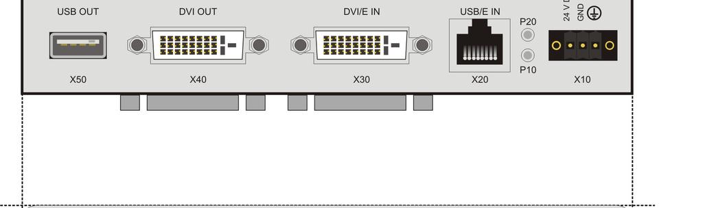
7 Product Overview 2.3 Dimensions CU

. The USB plug will be connected to the unit.")

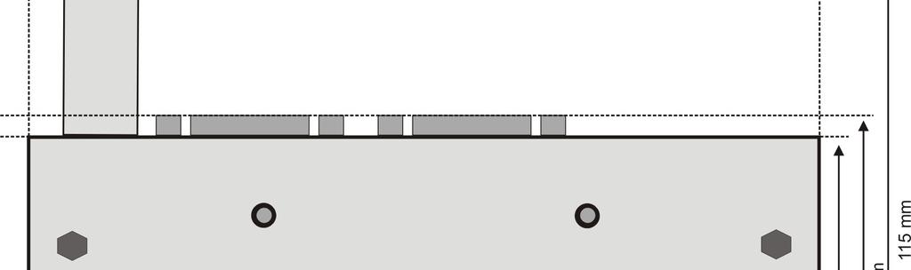
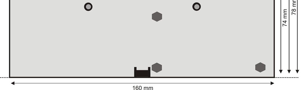
8 Installation 3 Installation 3.1 Installing USB cable strain relief All plugs, connected to the unit, have an integrated stain relief, except the USB plug. To provide the USB plug from disconnecting, a bracket must be installed on the front of the unit. The bracket has the following measures: The bracket is fixed with a screw (M3, 4 mm). The USB plug will be connected to the unit. The cable is place through the slot in the middle of the bracket. (see picture) 3.2 Mounting / Unmounting The USB-Extender-RX CU can be installed in two ways. There are two versions of mounting kits to install the unit (a) onto a planar surface or (b) onto a 35 mm mounting rail that conforms to EN Mounting on a planar surface First the installation on planar surfaces is described. The kit has the following measures: CU


9 Installation It will be fixed on the backside of the unit with four screws (4 x M3, 4 mm). The four notches can be used to fix the unit on the surface. The following picture shows how to fix the plate on the unit. The device has no restrictions for installation positions. The following picture shows some variations. CU

.")

10 Installation Mounting on a 35 mm mounting rail Alternative the unit can be installed on a mounting rail. To use this installation option an adapter for the rail is needed. It can be ordered together with the unit. The adapter is fixed with four screws (M3, 4 mm). The picture shows the installation position: The unit is snapped onto the rail as follows: 1. Lower the backside of the installed adapter onto the rail and press it down. 2. Push the unit towards the rail until it snaps in. To release the CU from the mounting rail: 3. Press down the unit until it gets loose on the rail 4. Pull the unit from the mounting rail CU

, rated maximum 4 Amp. by a 24 V DC power source, that has to satisfy NEC class 2.")
11 Installation 3.3 Power Supply The USB-Extender-Rx CU8860 can be powered by an additional power supply (X10). If a USB device needs more than 100 ma the additional power supply must be connected. The pins have to be connected as shown in the picture below UL requirements Danger For the compliance of the UL requirements the USB-Extender-Rx should only be supplied by a 24 V DC supply voltage, supplied by an isolating source and protected by means of a fuse (in accordance with UL248), rated maximum 4 Amp. by a 24 V DC power source, that has to satisfy NEC class 2. A class 2 power supply shall not be connected in series or parallel with another (class 2) power source! To meet the UL requirements, the USB hub CU must not be connected to unlimited power sources! CU

 (standard CAT5 cable) Pin Signal Assignment 1 15 V 15 V + 2")
12 Installation 3.4 Data - Connectors The connector are 1 USB port Type A, a RJ45-connector and 2 DVI-Sockets. The pins are described below: USB type A Port (X50) (standard cable) Pin Assignment 1 VCC 2 Data - 3 Data + 4 GND Shell Shield RJ 45 Port (X20) (standard CAT5 cable) Pin Signal Assignment 1 15 V 15 V + 2 GND Ground 3 TX USB TX 4 RX USB RX 5 RX USB RX 6 TX USB TX 7 15 V 15 V + 8 GND Ground CU


13 Installation DVI D Port (X30 / X40) Pin Assignment Pin Assignment Pin Assignment 1 TMDS data 2-9 TMDS data 1-17 TMDS data 0-2 TMDS data TMDS data TMDS data 0+ 3 TMDS data 2/4 Shield 11 TMDS data 1/3 shield 19 TMDS data 0/5 shield 4 not connected 12 not connected 20 not connected 5 not connected 13 not connected 21 not connected 6 DDC clock V Power 22 TMDS clock shield 7 DDC data 15 ground ( +5 V, Analog 23 TMDS clock + H/V Sync) 8 analog vertical sync 16 hot plug detect 24 TMDS clock LED Diagnostics The following table shows the possible states for the LEDs: LED Allocation State Meaning P10 Power load on USB port green red current < 500 ma current > 500 ma P20 DVI-Link green DVI signal is connected (clock signal is sensed) red DVI signal is not connected (No clock signal is sensed) CU
 and USB-Extender-RX (CU8860) the length of USB data transmission can be increased from 35 meters (1 host, 5 USB hubs and a device")
 contains no additional USB hub.")
14 Installation 3.6 Architecture Description Within the USB-Extender-TX (CU8800) and USB-Extender-RX (CU8860) the length of USB data transmission can be increased from 35 meters (1 host, 5 USB hubs and a device connected with 5 meters cable) up to 61 meters. Due to the USB signal runtime, it is not possible to connect more than one USB hub in the chain. The DVI signals are extended up to 55 meters. The following pictures show the maximal length of connection for possible configurations: This configuration (1) contains no additional USB hub. The maximal distance of extension is 56 meters: 1 meter of cable to the extension box CU8800; up to 50 meters extension cable and 5 meters from extension box to USB device. The DVI cable can have a maximal length of 50 meters to the extension box. From there the DVI signal can be transmitted up to 5 meters. This configuration (2) contains an additional USB hub. The USB hub is connected directly to the host computer. The maximal distance of extension is 61 meters: 5 meters of cable from USB host to the USB hub; 1 meter cable to the extension box CU8800; up to 50 meters extension cable and 5 meters from extension box to USB device. The DVI Signal is also extended to maximum 55 meters. (see configuration1) CU

15 Installation The third configuration (3) has nearly the same structure than configuration 2. The USB hub is connected after the extension. Due to signal quality the maximal distance is 59 meters: 1 meter of cable from USB host to the USB extension box CU8800; up to 50 meters extension cable; 5 meters from extension box to USB hub and 3 meters of cable to the USB device. The DVI Signal is also extended to maximum 55 meters. (see configuration1) CU
16 Approvals for USA and Canada 4 Approvals for USA and Canada 4.1 FCC Approval for USA FCC: Federal Communications Commission Radio Frequency Interference Statement This equipment has been tested and found to comply with the limits for a Class A digital device, pursuant to Part 15 of the FCC Rules. These limits are designed to provide reasonable protection against harmful interference when the equipment is operated in a commercial environment. This equipment generates, uses, and can radiate radio frequency energy and, if not installed and used in accordance with the instruction manual, may cause harmful interference to radio communications. Operation of this equipment in a residential area is likely to cause harmful interference in which case the user will be required to correct the interference at his own expense. 4.2 FCC Approval for Canada FCC: Canadian Notice This equipment does not exceed the Class A limits for radiated emissions as described in the Radio Interference Regulations of the Canadian Department of Communications. CU
17 Appendix 5 Appendix 5.1 Beckhoff support and service Beckhoff and their partners around the world offer comprehensive support and service, making available fast and competent assistance with all questions related to Beckhoff products and system solutions Beckhoff support Support offers you comprehensive technical assistance, helping you no only with the application of individual Beckhoff products, but also with other, wide-ranging services: world-wide support design, programming and commissioning of complex automation systems and extensive training program for Beckhoff system components Hotline: + 49 (0) 5246/ Fax: + 49 (0) 5246/ support@beckhoff.com Beckhoff service The Beckhoff Service Center supports you in all matters of after-sales service: on-site service repair service spare parts service hotline service Hotline: + 49 (0) 5246/ Fax: + 49 (0) 5246/ service@beckhoff.com You will find further support and service addresses on our internet pages under Beckhoff headquarters Beckhoff Automation GmbH Eiserstr Verl Germany Phone: + 49 (0) 5246/963-0 Fax: + 49 (0) 5246/ info@beckhoff.de Web: The addresses of Beckhoff s branch offices and representatives round the world can be found on her internet pages: You will also find further documentation for Beckhoff components there. CU
CU port USB 2.0 hub. Version: 1.1 Date:
 CU8004-0000 4 port USB 2.0 hub Version: 1.1 Date: 2006-08-11 Table of Contents Table of Contents 1 Foreword 1 1.1 Notes on the documentation 1 1.1.1 Liability Conditions 1 1.1.2 Conditions of delivery
CU Compact-Flash card adapter for USB. Version: 1.0 Date:
 CU8870-0000 Compact-Flash card adapter for USB Version: 1.0 Date: 2007-06-15 Table of Contents Table of Contents 1 Foreword 1 1.1 Notes on the documentation 1 1.1.1 Liability Conditions 1 1.1.2 Conditions
Installation- and Operating instructions for CU Ethernet Controller with USB Input. Version: 1.4 Date:
 Installation- and Operating instructions for CU8880-0010 Ethernet Controller with USB Input Version: 1.4 Date: 2018-04-12 Table of contents Table of contents 1. 2. 3. 4. 5. General instructions 2 Notes
Installation- and Operating instructions for CU Port USB 2.0 Hub. Version: 1.3 Date:
 Installation- and Operating instructions for CU8005-0000 4-Port USB 2.0 Hub Version: 1.3 Date: 2018-04-27 Table of contents Table of contents 1 Foreword 3 1.1 Notes on the Documentation 3 1.1.1 Liability
Installation- and Operating instructions for CU Port USB 3.0 Hub. Version: 1.1 Date:
 Installation- and Operating instructions for CU8006-0000 4-Port USB 3.0 Hub Version: 1.1 Date: 2018-04-27 Table of contents Table of contents 1 Foreword 3 1.1 Notes on the Documentation 3 1.1.1 Liability
Installation- and Operating instructions for CU CFast card adapter with USB connector. Version: 1.1 Date:
 Installation- and Operating instructions for CU8871-0000 CFast card adapter with USB connector Version: 1.1 Date: 2013-12-06 Table of contents Table of contents 1 Foreword 3 1.1 Notes on the Documentation
C9900-P223 and C9900-P224
 Installation and Operating instructions for C9900-P223 and C9900-P224 Power Supply Units Version: 1.2 Date: 2012-02-22 Table of contents Table of contents 1. Foreword 2 Notes on the Documentation 2 Liability
Installation- and Operating instructions for CU CP-Link 4 transmitter box The Two Cable Display Link. Version: 1.
 Installation- and Operating instructions for CU8802-0000 CP-Link 4 transmitter box The Two Cable Display Link Version: 1.1 Date: 2015-08-27 Table of contents Table of contents 1 Foreword 3 1.1 Notes on
Operation Manual BK5000. Bus Coupler for CAN-CAL Version: 1.12
 Operation Manual BK5000 Bus Coupler for CAN-CAL 2006-11-27 Version: 1.12 Table of Contents Table of Contents 1. Foreword 1 Notes on the documentation 1 Safety Instructions 2 2. Configuration of the Bus
Documentation KM2042. Sixteen channel digital output module with D-Sub Connector. Version: Date:
 Documentation Sixteen channel digital output module with D-Sub Connector Version: Date: 2.0.0 2017-11-20 Table of contents Table of contents 1 Foreword... 5 1.1 Notes on the documentation... 5 1.2 Safety
C9900-P208 and C9900-P209
 Installation and Operating instructions for C9900-P208 and C9900-P209 Power Supply Units Version: 1.5 Date: 2012-02-22 Table of contents Table of contents 1. Foreword 2 Notes on the Documentation 2 Liability
Documentation EM2042. Sixteen Channel Digital Output Module with D-Sub Connector. Version: Date:
 Documentation Sixteen Channel Digital Output Module with D-Sub Connector Version: Date: 2.0 2016-08-03 Table of contents Table of contents 1 Foreword... 4 1.1 Notes on the documentation... 4 1.2 Safety
Documentation. CU20xx, CU22xx. Ethernet Switch. Version: Date:
 Documentation CU20xx, CU22xx Ethernet Switch Version: Date: 2.1 2017-12-18 CU20xx, CU22xx - Product overview 1 CU20xx, CU22xx - Product overview CU2005 [} 8] - 5 RJ-45-Ethernet-Ports CU2008 [} 8] - 8
Documentation ZB8610. Fan cartridge for EtherCAT and Bus Terminals. Version: Date:
 Documentation Fan cartridge for EtherCAT and Bus Terminals Version: Date: 1.5 2017-08-07 Table of contents Table of contents 1 Foreword... 5 1.1 Notes on the documentation... 5 1.2 Safety instructions...
Documentation. KM2604 and KM2614. Four channel relay module. Version: Date:
 Documentation KM2604 and KM2614 Four channel relay module Version: Date: 2.1.0 2017-12-01 Tabel of contents Tabel of contents 1 Foreword... 5 1.1 Notes on the documentation... 5 1.2 Safety instructions...
EL9820/EL9821 Evaluation Kit. Version: 1.3 Date:
 EL9820/EL9821 Evaluation Kit Version: 1.3 Date: 2015-05-25 Table of contents Table of contents 1 Foreword 2 1.1 Notes on the documentation 2 1.1.1 Liability conditions 2 1.1.2 Delivery conditions 2 1.1.3
Installation and Operating instructions for Control Cabinet PCs C63xx
 Installation and Operating instructions for Control Cabinet PCs C63xx - 0020 Version: 1.4 Date: 2009-08-20 Table of contents Table of contents 1. 2. 3. 4. 5. General instructions 3 Notes on the Documentation
Installation and Operating instructions for Built-in Industrial PC C6525
 Installation and Operating instructions for Built-in Industrial PC C6525 Version: 1.0 Date: 2008-11-03 Table of contents Table of contents 1. 2. 3. 4. 5. General Notes 3 Notes on the Documentation 3 Liability
Installation and Operating instructions for Industrial PC series C61xx
 Installation and Operating instructions for Industrial PC series C61xx Version: 2.2 Date: 2007-02-09 Table of contents Table of contents 1. 2. 3. 4. General instructions 3 Notes on the Documentation 3
Documentation. KM10xx. Terminal Modules with Digital Inputs. Version: Date:
 Documentation KM10xx Terminal Modules with Digital Inputs Version: Date: 3.1.0 2017-01-23 Product overview KM10xx Product overview KM10xx KM1002, KM1012 [} 11] - 16 inputs, input filter 3 or 0.2 ms KM1004,
Installation and Operating instructions for. Control Cabinet PC C6210. Version: 1.4 Date:
 Installation and Operating instructions for Control Cabinet PC C6210 Version: 1.4 Date: 2016-12-12 Table of contents Table of contents 1. 2. 3. 4. 5. 6. 7. General instructions 3 Notes on the Documentation
Documentation KM2002, KM2004, KM2008. Terminal modules with digital outputs, 24 V, 0.5 A. Version: Date:
 Documentation KM2002, KM2004, KM2008 Terminal modules with digital outputs, 24 V, 0.5 A Version: Date: 3.2.0 2017-01-23 Table of contents Table of contents 1 Foreword... 4 1.1 Notes on the documentation...
Operating instructions for AX5801. TwinSAFE drive option card for the AX5000 servo drive. Version: Date:
 Operating instructions for AX5801 TwinSAFE drive option card for the AX5000 servo drive Version: 1.2.0 Date: 2016-03-15 Table of contents Table of contents 1 Foreword 3 1.1 Notes on the manual 3 1.1.1
Documentation. Mains filter AX2090-NF50. Version: Date:
 Documentation Mains filter AX2090-NF50 Version: Date: 1.1 2015-11-11 Table of content Table of content 1 Foreword... 4 1.1 Notes on the documentation... 4 1.2 Documentation issue status... 5 1.3 Appropriate
Installation and Operating instructions for. Built-in Control Panel CP6608. Version: 1.0 Date:
 Installation and Operating instructions for Built-in Control Panel CP6608 Version: 1.0 Date: 2008-02-07 General Notes Table of contents 1. 2. 3. 4. 5. 6. General Notes 2 Notes on the documentation 2 Liability
DeviceNet ILxxxx-B520. IO Data Mapping DeviceNet Objects Indicators and Switches
 DeviceNet ILxxxx-B520 IO Data Mapping DeviceNet Objects Indicators and Switches Version: 1.2 08.11.2006 Please note the following Target group Safety requirements This description is only intended for
Installation and Operating instructions for C / Fanless Control Cabinet Industrial PC. Version: 1.0 Date:
 Installation and Operating instructions for C6925-0020/-0030 Fanless Control Cabinet Industrial PC Version: 1.0 Date: 2016-05-27 Table of contents Table of contents 1 Foreword 3 1.1 Notes on the Documentation
Installation and Operating instructions for Industrial PC series C61xx from Version: 3.0 Date:
 Installation and Operating instructions for Industrial PC series C61xx from -0060 Version: 3.0 Date: 2018-02-16 Table of contents Table of contents 1. 2. 3. 4. 5. General instructions 3 Notes on the Documentation
Installation and Operating instructions for Control Cabinet PC C6915
 Installation and Operating instructions for Control Cabinet PC C6915 Version: 1.2 Date: 2010-09-22 Table of contents Table of contents 1. 2. 3. 4. Foreword 3 Notes on the Documentation 3 Liability Conditions
Installation and Operating instructions for. Control Cabinet PC C6240 from Version: 2.0 Date:
 Installation and Operating instructions for Control Cabinet PC C6240 from -0060 Version: 2.0 Date: 2018-02-16 Table of contents Table of contents 1. 2. 3. 4. 5. 6. 7. General instructions 3 Notes on the
Installation and Operating instructions for. Control Cabinet PC C6250 up to Version: 1.6 Date:
 Installation and Operating instructions for Control Cabinet PC C6250 up to -0060 Version: 1.6 Date: 2018-02-16 Table of contents Table of contents 1. 2. 3. 4. General instructions 3 Notes on the Documentation
Installation and Operating instructions for Industrial PC series C61xx up to Version: 2.6 Date:
 Installation and Operating instructions for Industrial PC series C61xx up to -0050 Version: 2.6 Date: 2018-02-16 Table of contents Table of contents 1. 2. 3. 4. General instructions 3 Notes on the Documentation
Installation and Operating instructions for C Ultra compact Industrial PC. Version: 1.3 Date:
 Installation and Operating instructions for C6015-0010 Ultra compact Industrial PC Version: 1.3 Date: 2018-04-12 Table of contents Table of contents 1 Foreword 3 1.1 Notes on the Documentation 3 1.1.1
Documentation KL channel Digital Output Terminal, 24 V DC, 2 x 4 A/1 x 8 A. Version: Date:
 Documentation 2 channel Digital Output Terminal, 24 V DC, 2 x 4 A/1 x 8 A Version: Date: 1.0.0 2016-08-12 Table of contents Table of contents 1 Foreword... 4 1.1 Notes on the documentation... 4 1.2 Safety
KL , KS
 Configuration Instructions for KL5111-0000, KS5111-0000 Interface Terminal for Incremental Encoder Version: 3.0.1 Date: 2008-09-16 Table of Contents Table of Contents 1 Foreword 2 1.1 Notes on the Documentation
KL Channel Resistor Bridge Input Terminal Configuration Instructions
 KL3351 1-Channel Resistor Bridge Input Terminal Configuration Instructions Version 2.2 2006-10-23 Contents Contents 1. Foreword 3 Notes on the documentation 3 Safety Instructions 4 2. Technical data 5
EL9800 Base Board. Version: 1.9 Date:
 EL9800 Base Board Version: 1.9 Date: 2007-07-25 Table of contents Table of contents 1 Foreword 2 1.1 Notes on the documentation 2 1.1.1 Liability conditions 2 1.1.2 Delivery conditions 2 1.1.3 Copyright
Installation- and Operating instructions for. Build-in Industrial PCs C3620, C3640 from Version: 3.0 Date:
 Installation- and Operating instructions for Build-in Industrial PCs C3620, C3640 from -0060 Version: 3.0 Date: 2018-02-16 Table of contents Table of contents 1. 2. 3. 4. 5. General instructions 3 Notes
KL Channel Analog Input Terminal 10 V V Configuration Instructions. Version
 KL3102 2-Channel Analog Input Terminal 10 V...+10 V Configuration Instructions Version 2.0.2 2006-10-23 Contents Contents 1. Foreword 3 Notes on the documentation 3 Safety Instructions 4 2. Technical data
Installation and Operating instructions for CP78xx Control Panel. Version: 1.8 Date:
 Installation and Operating instructions for CP78xx Control Panel Version: 1.8 Date: 2016-03-14 Table of contents Table of contents 1. 2. 3. 4. 5. 6. General Notes 2 Notes on the documentation 2 Liability
19-inch slide-in Industrial PC C5210
 Installation and Operating instructions for 19-inch slide-in Industrial PC C5210 Version: 1.2 Date: 2016-12-08 Table of contents Table of contents 1 Foreword 4 1.1 Notes on the Documentation 4 1.1.1 Liability
Lantech. IPES /100TX with 4 PoE Injectors 24~48VDC Industrial Switch. User Manual
 Lantech IPES-0008-4 8 10/100TX with 4 PoE Injectors 24~48VDC Industrial Switch User Manual V1.00 Jun 2010 FCC Warning This Equipment has been tested and found to comply with the limits for a Class-A digital
Installation and Operating instructions for. CP790x-140x. IP65 Stainless Control Panel. Version: 1.1 Date:
 Installation and Operating instructions for CP790x-140x IP65 Stainless Control Panel Version: 1.1 Date: 2013-01-17 Table of contents Table of contents 1 Foreword 3 1.1 Notes on the Documentation 3 1.1.1
Installation and Operating instructions for. CP27xx. Fanless multi-touch built-in Panel PC. Version: 1.0 Date:
 Installation and Operating instructions for CP27xx Fanless multi-touch built-in Panel PC Version: 1.0 Date: 2015-09-25 Table of contents Table of contents 1 Foreword 4 1.1 Notes on the Documentation 4
CP29xx-0010 Multi-touch Control Panel with CP-Link 4 interface
 Installation and Operating instructions for CP29xx-0000 Multi-touch Control Panel with DVI/ USB Extended interface CP29xx-0010 Multi-touch Control Panel with CP-Link 4 interface Version: 1.8 Date: 2015-08-27
Installation and Operating instructions for. CP79xx Control Panel. Version: 1.5 Date:
 Installation and Operating instructions for CP79xx Control Panel Version: 1.5 Date: 2011-06-27 Table of contents Table of contents 1. 2. 3. 4. 5. 6. Foreword 2 Notes on the Documentation 2 Liability Conditions
CP39xx-0010 Multi-touch Control Panel with CP-Link 4 interface
 Installation and Operating instructions for CP39xx-0000 Multi-touch Control Panel with DVI/ USB Extended interface CP39xx-0010 Multi-touch Control Panel with CP-Link 4 interface Version: 2.2 Date: 2016-06-30
Installation and Operating instructions for. Control Cabinet Industrial PC C from Version: 2.0 Date:
 Installation and Operating instructions for Control Cabinet Industrial PC C6240-1007 from -0060 Version: 2.0 Date: 2018-02-16 Table of contents Table of contents 1. 2. 3. 4. Foreword 3 Notes on the Documentation
Installation and Operating instructions for CP / CP Economy Built-in Panel PC. Version: 1.
 Installation and Operating instructions for CP6600-0001-0020/ CP6606-0001-0020 Economy Built-in Panel PC Version: 1.3 Date: 2017-12-05 Table of contents Table of contents 1 Foreword 3 1.1 Notes on the
4 10/100/1000T Mini-GBIC with 4 IEEE 802.3at High Power PoE Industrial Wide Temperature Switch. User Manual SISTP LRT
 4 10/100/1000T + 2 1000 Mini-GBIC with 4 IEEE 802.3at High Power PoE Industrial Wide Temperature Switch User Manual V1.0 September-2013 FCC Warning This Equipment has been tested and found to comply with
MC 11 EB-2 Power supply cabinet with external bus, AC version
 MC 11 EB-2 Power supply cabinet with external bus, AC version USER/MAINTENANCE MANUAL 1 SLOT 0 SLOT 1 SLOT 2 SLOT 3 SLOT 4 SLOT 5 SLOT 6 SLOT 7 SLOT 8 SLOT 9 SLOT 10 SLOT 11 EB-2 (a) MC11 (b) (c) Figures
Control Cabinet Industrial PC C6640/ C6650 up to -0030
 Installation and Operating instructions for Control Cabinet Industrial PC C6640/ C6650 up to -0030 Version: 1.6 Date: 2018-01-24 Table of contents Table of contents 1. 2. 3. Foreword 3 Notes on the Documentation
Serial PROFIBUS Interface
 Installation Manual Serial PROFIBUS Interface Version: EN-062016-2.3 Copyright 2016 Softing Industrial Automation GmbH Disclaimer of liability The information contained in these instructions corresponds
10/100/1000T to Mini-GBIC Industrial Switch Converter 10/100/1000T to 1000SX/LX Industrial Switch Converter. AMG9011G-H (-40 to 75C) User Manual
 User Manual") 10/100/1000T to Mini-GBIC Industrial Switch Converter 10/100/1000T to 1000SX/LX Industrial Switch Converter AMG9011G-H (-40 to 75C) User Manual www.amgsystems.com Content Overview...1 Introduction... 1
10/100/1000T to Mini-GBIC Industrial Switch Converter 10/100/1000T to 1000SX/LX Industrial Switch Converter AMG9011G-H (-40 to 75C) User Manual www.amgsystems.com Content Overview...1 Introduction... 1
Installation and Operating instructions for. CP79xx Control Panel. Version: 1.2 Date:
 Installation and Operating instructions for CP79xx Control Panel Version: 1.2 Date: 2007-11-05 Table of contents Table of contents 1. 2. 3. 4. 5. 6. General Notes 2 Notes on the documentation 2 Liability
Installation and Operating instructions for 19 Inch Rack Mount Industrial PC C5102 from -0060
 Installation and Operating instructions for 19 Inch Rack Mount Industrial PC C5102 from -0060 Version: 3.0 Date: 2018-02-16 Foreword Table of contents 1. 2. 3. 4. 5. Foreword 4 Notes on the Documentation
4-port 10/100TX + 1 or 2-port 100FX Industrial Switch. User Manual
 4-port 10/100TX + 1 or 2-port 100FX Industrial Switch User Manual Rev.1.03 Sep-2010 FCC Warning This Equipment has been tested and found to comply with the limits for a Class A digital device, pursuant
Installation and Operating instructions for. CP69xx. Built-in Control Panel with DVI/ USB Extended interface. Version: 2.
 Installation and Operating instructions for CP69xx Built-in Control Panel with DVI/ USB Extended interface Version: 2.4 Date: 2017-01-06 Table of contents Table of contents 1 Foreword 3 1.1 Notes on the
Industrial Ethernet Switch
 Quick Start Guide This quick start guide describes how to install and use the hardened Ethernet Switch. Capable of operating at temperature extremes of -10 C to +60 C, this is the switch of choice for
Installation and Operating instructions for. C inch slide-in Industrial PC. Version: 1.0 Date:
 Installation and Operating instructions for C5240 19-inch slide-in Industrial PC Version: 1.0 Date: 2019-02-08 Table of contents Table of contents 1 Foreword 4 1.1 Notes on the Documentation 4 1.1.1 Liability
Operating Instructions (Compact) SIMATIC. Industrial PC SIMATIC Microbox PC 420. Siemens. Release 11/2006 A5E
 SIMATIC. Industrial PC SIMATIC Microbox PC 420. Siemens. Release 11/2006 A5E") Operating Instructions (Compact) 1 SIMATIC Industrial PC Release 11/2006 A5E00344128-04 Siemens Safety Guidelines This manual contains notices you have to observe in order to ensure your personal safety,
Operating Instructions (Compact) 1 SIMATIC Industrial PC Release 11/2006 A5E00344128-04 Siemens Safety Guidelines This manual contains notices you have to observe in order to ensure your personal safety,
Installation and Operating instructions for. Built-in Control Panel CP68xx. Version: 2.0 Date:
 Installation and Operating instructions for Built-in Control Panel CP68xx Version: 2.0 Date: 2007-11-05 General Notes Table of contents 1. 2. 3. 4. 5. 6. General Notes 2 Notes on the documentation 2 Liability
Installation and Operating instructions for CP / CP Economy Built-in Panel PC. Version: 1.
 Installation and Operating instructions for CP6700-0001-0050/ CP6706-0001-0050 Economy Built-in Panel PC Version: 1.1 Date: 2017-12-13 Table of contents Table of contents 1 Foreword 3 1.1 Notes on the
Description AX5805. List of permissible motors. Version: Date:
 Description AX5805 List of permissible motors Version: 1.6.0 Date: 2017-11-15 Table of contents Table of contents 1 Foreword 3 1.1 Notes on the manual 3 1.1.1 Intendent audience 3 1.1.2 Origin of the
Installation and Operating instructions for Build-in Industrial PC C33xx up to -0050
 Installation and Operating instructions for Build-in Industrial PC C33xx up to -0050 Version: 1.5 Date: 2018-01-31 Foreword Table of contents 1. 2. 3. 4. Foreword 3 Notes on the Documentation 3 Liability
LNP series. 5-port Industrial PoE+ Unmanaged Ethernet Switches 4*10/100Tx (30W/Port) + 1*10/100Tx, 12~36VDC Input.
 + 1*10/100Tx, 12~36VDC Input.") LNP-0500-24 series 5-port Industrial PoE+ Unmanaged Ethernet Switches 4*10/100Tx (30W/Port) + 1*10/100Tx, 12~36VDC Input User Manual FCC Warning This Equipment has been tested and found to comply with
LNP-0500-24 series 5-port Industrial PoE+ Unmanaged Ethernet Switches 4*10/100Tx (30W/Port) + 1*10/100Tx, 12~36VDC Input User Manual FCC Warning This Equipment has been tested and found to comply with
User Guide CPSMP VAC Power Supply Module: PointSystem CPSMC Accessory CPSMC Accessory. Contents.
 User Guide CPSMP-205 110 240 VAC Power Supply Module: PointSystem CPSMC1800-200 Accessory CPSMC1900-100 Accessory Contents Contents...1 Description...1 Cautions and Warnings...2 Definitions...2 Power supply
KL6001 Serial interface RS 232 C Configuration Instructions. Version
 KL6001 Serial interface RS 232 C Configuration Instructions Version 2.02 2006-10-24 Contents Contents 1. Foreword 3 Notes on the documentation 3 Safety Instructions 4 2. Technical data 5 3. Description
Industrial 5-Port Fast Ethernet Switches with SFP Slot and optional 4 PoE PSE Ports. Basic Model: KSD-541 PoE Model: KSD-541-P. Installation Guide
 Industrial 5-Port Fast Ethernet Switches with SFP Slot and optional 4 PoE PSE Ports Basic Model: KSD-541 PoE Model: KSD-541-P Installation Guide DOC.080104-1- (C) 2008 KTI Networks Inc. All rights reserved.
KSD-800 Series. Installation Guide. Industrial 8-Port Fast Ethernet Switches with Fiber Connectivity DOC A -1-
 KSD-800 Series Industrial 8-Port Fast Ethernet Switches with Fiber Connectivity Installation Guide DOC.110516A -1- (C) 2005 KTI Networks Inc. All rights reserved. No part of this documentation may be reproduced
IEC-0101FT Industrial 10/100TX to 100M-FX Slim Type Converter User Manual
 Lantech IEC-0101FT Industrial 10/100TX to 100M-FX Slim Type Converter User Manual FCC Warning This Equipment has been tested and found to comply with the limits for a Class A digital device, pursuant to
Installation and Maintenance
 Installation and Maintenance TT1000 TT3000 TT4000 Version 1.3 e-data GmbH 01.2009 Version 1.3 1-1 1 Usage 1-3 1.1 Protection Class and Protection Type... 1-3 1.2 Safety Measures... 1-3 1.3 Before Commissioning...
Redundancy unit CP-A RU
 2CDC 271 010 F0t06 Features Decoupling of CP power supply units with 2 inputs, each up to 20 A per input / channel Output up to 40 A True redundancy by 100 % decoupling of two parallel connected power
Industriefunkuhren. Technical Manual. Signal Converter. for DIN Rail Mounting Series 4800xx-yy ENGLISH
 Industriefunkuhren Technical Manual Signal Converter for DIN Rail Mounting Series 4800xx-yy ENGLISH Version: 01.01-19.07.2007 2 / 23 Signal Converter 4800 - V01.01 INPORTANT NOTES Downloading Technical
10/100TX to 100FX w/ 1 PoE Injector Industrial Media Converter User Manual
 10/100TX to 100FX w/ 1 PoE Injector Industrial Media Converter User Manual v1.02 FCC Warning This Equipment has been tested and found to comply with the limits for a Class-A digital device, pursuant to
HEC. General Operating, Maintenance and Installation Manual
 HEC General Operating, Maintenance and Installation Manual D-91056 Erlangen Phone: +49 9131 7677 47 Fax: +49 9131 7677 78 Internet : http://www.ipcomm.de Email: info@ipcomm.de Edition November 2005 Version
Documentation. AL225x Connector-Box. Accessory for servo drives of the series AX5000 and AX2000. Version: Date:
 Documentation Accessory for servo drives of the series AX5000 and AX2000 Version: Date: 1.8 2018-01-16 Contents Contents 1 Foreword... 5 1.1 Notes on the documentation... 5 1.2 Documentation Issue Status...
5/8-Port Industrial Fast Ethernet Switch ISW-500/ISW-800. User's Manual
 5/8-Port Industrial Fast Ethernet Switch ISW-500/ISW-800 User's Manual Trademarks Copyright PLANET Technology Corp. 2006. Contents subject to which revision without prior notice. PLANET is a registered
Installation and Operating instructions for. Economy built-in Panel PC CP62x9. Version: 1.0 Date:
 Installation and Operating instructions for Economy built-in Panel PC CP62x9 Version: 1.0 Date: 2010-03-29 Foreword Table of contents 1. 2. 3. 4. Foreword 3 Notes on the Documentation 3 Liability Conditions
LNP-0602 series. 6-port Industrial PoE+ Unmanaged Ethernet Switches 4*10/100Tx (30W/Port) + 2*100Fx. User Manual
 + 2*100Fx. User Manual") LNP-0602 series 6-port Industrial PoE+ Unmanaged Ethernet Switches 4*10/100Tx (30W/Port) + 2*100Fx User Manual FCC Warning This Equipment has been tested and found to comply with the limits for a Class-A
LNP-0602 series 6-port Industrial PoE+ Unmanaged Ethernet Switches 4*10/100Tx (30W/Port) + 2*100Fx User Manual FCC Warning This Equipment has been tested and found to comply with the limits for a Class-A
Installation and Operating instructions for. CP37xx. Multi-touch Panel PC. Version: 1.2 Date:
 Installation and Operating instructions for CP37xx Multi-touch Panel PC Version: 1.2 Date: 2018-04-12 Table of contents Table of contents 1 Foreword 3 1.1 Notes on the Documentation 3 1.1.1 Liability
6 10/100/1000TX + 2G Fiber Industrial Ethernet Switch User Manual
 6 10/100/1000TX + 2G Fiber Industrial Ethernet Switch User Manual FCC Warning This Equipment has been tested and found to comply with the limits for a Class-A digital device, pursuant to Part 15 of the
IMC-21 Quick Installation Guide
 IMC-21 Quick Installation Guide Moxa Industrial Media Converter Edition 5.0, February 2017 Technical Support Contact Information www.moxa.com/support Moxa Americas: Toll-free: 1-888-669-2872 Tel: 1-714-528-6777
COGNEX. Checker SensorView. Quick Reference Guide
 COGNEX Checker SensorView Quick Reference Guide 890 SensorView 890 Overview SensorView 890 provides self-contained IP-65 touchscreen configuration, control, and monitoring of one or more Checker 4G series
Installation and Operating instructions for. Panel-PC CP71xx. Version: 1.4 Date:
 Installation and Operating instructions for Panel-PC CP71xx Version: 1.4 Date: 2007-11-08 Table of contents 1. 2. 3. 4. 5. Table of contents General Notes 3 Notes on the documentation 3 Liability conditions
Device Server for the conversion of serial interfaces (RS-232/422/485) to IP.
 to IP.") Manual Entry Line Industrial Gigabit Ethernet Switch 4x 10/100/1000Base-T, 1x SFP Ports MICROSENS General The IP protocol has already left the in-house environment and is going to take all remaining communication
Manual Entry Line Industrial Gigabit Ethernet Switch 4x 10/100/1000Base-T, 1x SFP Ports MICROSENS General The IP protocol has already left the in-house environment and is going to take all remaining communication
Hardware Manual RM CANview
 Hardware Manual RM CANview 1998-2005 RM Michaelides Software & Elektronik GmbH Donaustraße 14 D-36043 Fulda Germany cv_hw_e.doc Table of Contents 1 Legal Regulations...3 2 About the CANview...4 3 Important
8-port 10/100TX + 2-Port 10/100/1000T/100/1000 SFP Combo with 8 PoE Injectors Industrial Ethernet Switch User Manual
 8-port 10/100TX + 2-Port 10/100/1000T/100/1000 SFP Combo with 8 PoE Injectors Industrial Ethernet Switch User Manual FCC Warning This Equipment has been tested and found to comply with the limits for a
Documentation. KL28xx. HD Bus Terminals, digital output 24 V DC. Version: Date:
 Documentation KL28xx HD Bus Terminals, digital output 24 V DC Version: Date: 1.0.0 2016-12-15 Product overview: digital output terminals 1 Product overview: digital output terminals KL2808 [} 8] (8 digital
DVI Extender over Single CAT5 Model #: DVI-C5-M-SET
 DVI Extender over Single CAT5 Model #: DVI-C5-M-SET 2013 Avenview Inc. All rights reserved. The contents of this document are provided in connection with Avenview Inc. ( Avenview ) products. Avenview makes
Hardened Ethernet to VDSL2 Extender. User Guide. Revision History. Industrial Ethernet to VDSL2 Extender with Wide Operating Temp. Rev.1.
 Hardened Ethernet to VDSL2 Extender User Guide Revision History Rev.1.03 Dec 2009 Industrial Ethernet to VDSL2 Extender with Wide Operating Temp. Document Release Date Revision Initials 1.00 Jun 04, 2009
onlinecomponents.com
 Repeater for RS-485 2-Wire Systems INTERFACE Data Sheet 102964_C01_en 1 Description The PSI-REP-RS485W2 DIN-rail mountable, modular RS-485 repeater is designed to meet the high requirements associated
DVI Extender over Single CAT5 Mini SET
 DVI Extender over Single CAT5 Mini SET Model #: DVI-C5-M-SET 2010 Avenview Inc. All rights reserved. The contents of this document are provided in connection with Avenview Inc. ( Avenview ) products. Avenview
UPort TM 200/400 Series Quick Installation Guide
 UPort TM 200/400 Series Quick Installation Guide Edition 4.0, November 2016 Technical Support Contact Information www.moxa.com/support Moxa Americas: Toll-free: 1-888-669-2872 Tel: 1-714-528-6777 Fax:
Operating manual ELX9012, ELX9410, ELX9560. ELX System Terminals. Version: Date:
 Operating manual ELX9012, ELX9410, ELX9560 ELX System Terminals Version: Date: 1.5.0 2018-08-08 Table of contents Table of contents 1 Foreword... 5 1.1 Notes on the documentation... 5 1.2 Safety instructions...
Industrial Ethernet Switch. Signamax Connectivity Systems. Industrial Ethernet Switch. Model A Series. User s Guide
 . Signamax Connectivity Systems Model 065-7405A Series User s Guide 1 Quick Start Guide This quick start guide describes how to install and use the Compact. Capable of operating at temperature extremes
Installation and Operating instructions for. Built-in Panel PC CP63xx. Version: 1.4 Date:
 Installation and Operating instructions for Built-in Panel PC CP63xx Version: 1.4 Date: 2007-11-26 Table of contents Table of contents 1. 2. 3. 4. General Notes 3 Notes on the Documentation 3 Liability
Hypercable injecteur HPOE - Industrial IEEE 802.3at Gigabit PoE Injector. User Manual. v.1.0 Jun Mail :
 Industrial IEEE 802.3at Gigabit PoE Injector User Manual v.1.0 Jun-2011 FCC Warning This Equipment has been tested and found to comply with the limits for a Class A digital device, pursuant to Part 15
Stacking Module. Installation Guide AT-MCF2000S. PN Rev A
 Stacking Module AT-MCF2000S Installation Guide PN 613-000708 Rev A Copyright 2007 Allied Telesis, Inc. All rights reserved. No part of this publication may be reproduced without prior written permission
Power Input Assignment Power1 12VDC DC Jack VDC Power2 - Power Ground
 Quick Start Guide This quick start guide describes how to install and use the Hardened Ethernet Extender. This is the Hardened Ethernet Extender of choice for harsh environments constrained by space. Physical