Object-Oriented Systems Development: Using the Unified Modeling Language
|
|
|
- Catherine McDaniel
- 6 years ago
- Views:
Transcription


1 Object-Oriented Systems Development: Using the Unified Modeling Language Chapter 4: Object-Oriented Methodologies
2 Goals Object-Oriented Methodologies The Rumbaugh et al. OMT The Booch methodology Jacobson's methodologies
3 Goals (Con t) Patterns Frameworks Unified Approach (UA) layered Architecture
4 Basic Definitions A methodology is explained as the science of methods. A method is a set of procedures in which a specific goal is approached step by step.
5 Too Many Methodologies 1986: Booch came up with the object-oriented design concept, the Booch method. 1987: Sally Shlaer and Steve Mellor came up with the concept of the recursive design approach.
6 Too Many Methodologies (Con t) 1989: Beck and Cunningham came up with class-responsibilitycollaboration (CRC) cards. 1990: Wirfs-Brock, Wilkerson, and Wiener came up with responsibilitydriven design. 1991: Peter Coad and Ed Yourdon developed the Coad lightweight and prototype-oriented approach.
7 Too Many Methodologies (Con t) 1991: Jim Rumbaugh led a team at the research labs of General Electric to develop the object modeling technique (OMT). 1994: Ivar Jacobson introduced the concept of the use case.
8 Survey of Some of the Object- Oriented Methodologies Many methodologies are available to choose from for system development. Here, we look at the methodologies developed by Rumbaugh et al., Booch, and Jacobson which are the origins of the Unified Modeling Language (UML) and the bases of the UA. The Rumbaugh et al. method is well-suited for describing the object model or static structure of the system. The Jacobson et.al method is good for producing user-driven analysis models The Booch method detailed object-oriented design models
9 Rumbaugh et. al. s Object Modeling Technique (OMT) OMT describes a method for the analysis, design, and implementation of a system using an object-oriented technique. Class, attributes, methods, inheritance, and association also can be expressed easily The dynamic behavior of objects within a system can be described using OMT Dynamic model Process description and consumer-producer relationships can expressed using OMT s Functional model Object-Oriented Systems Development Bahrami Irwin/ McGraw-Hill
10 OMT (Con t) OMT consists of four phases, which can be performed iteratively: 1. Analysis. The results are objects and dynamic and functional models. 2. System design. The result is a structure of the basic architecture of the system.
11 OMT (Con t) 3. Object design. This phase produces a design document, consisting of detailed objects and dynamic and functional models. 4. Implementation. This activity produces reusable, extendible, and robust code.
12 OMT Modeling OMT separates modeling into three different parts: 1. An object model, presented by the object model and the data dictionary. 2. A dynamic model, presented by the state diagrams and event flow diagrams. 3. A functional model, presented by data flow and constraints.
13 OMT Object Model The object model describes the structure of objects in a system: Their identity, relationships to other objects, attributes, and operations The object model is represented graphically with an object diagram The object diagram contains classes interconnected by association lines
14 Client OMT Object Model firstname lastname pincode ClientAccount number balance Account deposit withdraw createtransaction AccountTransaction Transaction transdate transtime transtype amount postbalance CheckingAccount Withdraw CheckingSavingAccount SavingsAccount
15 OMT Dynamic Model OMT dynamic model depict states, transitions, events, and actions OMT state transition diagram is a network of states and events Each state receives one or more events, at which time it makes the transition to the next state.
16 OMT Dynamic Model No account has been selected Nothing is selected Account has been selected Select Checking or saving account Select Checking account Select transaction type (withdraw, deposit, transfer) Enter the amount Confirmation
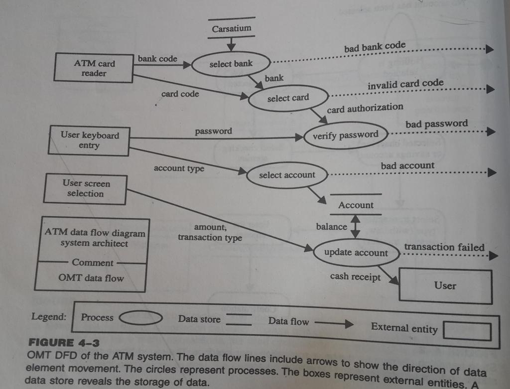
17 OMT Functional Model The OMT DFD shows the flow of data between different process in a business DFD use four primary symbols: Process is any function being performed ; For Ex, verify password or PIN in the ATM system Data flow shows the direction of data element movement: foe Ex. PIN code Data store is a location where data are stored: for ex. Account is a data store in the ATM example External entity is a source or destination of a data element; fro ex. The ATM card Reader
18 OMT Functional Model Data Store Process Client Account Data Flow Card Reader PIN Code Process PIN Code External Entity
19
20 The Booch Methodology The Booch methodology covers the analysis and design phases of systems development. Booch sometimes is criticized for his large set of symbols. You start with class and object diagram in the analysis phase and refine these diagrams in various steps
21 The Booch Methodology (Con t) The Booch method consists of the following diagrams: Class diagrams Object diagrams State transition diagrams Module diagrams Process diagrams Interaction diagrams
22 The Booch Methodology (Con t) Object Modeling using Booch Notation Car color manufacturer cost superclass inherits Ford inherits Mustang Taurus Escort
23 The Booch Methodology (Con t) an alarm class state transition diagram with Booch Operator::TurnOffAlarm notation Enabled Silenced SoundAlarm SilenceAlarm Sounding Enable Disable AlarmFixed Disabled
24 The Booch Methodology (Con t) The Booch methodology prescribes A macro development process Serve as a controlling framework for the micro process and can take weeks or even months The primary concern of the macro process is technical management of the system A micro development process.
25 The Macro Development Process The macro development process consists of the following steps: 1. Conceptualization : you establish the core requirements of the system You establish a set of goals and develop a prototype to prove the concept 2. Analysis and development of the model. You use the class diagram to describe the roles and responsibilities objects are to carry out in performing the desired behavior of the system You use the Object diagram to describe the desired behavior of the system in terms of scenarios or use the interaction diagram
26 The Macro Development Process 3. Design or create the system architecture. In this phases, You use the class diagram to decide what class exist and how they relate to each other Object diagram to used to regulate how objects collaborate Then use module diagram to map out where each class and object should be declared Process diagram determine to which processor to allocate a process 4. Evolution or implementation. refine the system through many iterations 5. Maintenance. - make localized changes the the system to add new requirements and
27 The Micro Development Process Each macro development process has its own micro development process The micro process is a description of the dayto-day activities by a single or small group of s/w developers The micro development process consists of the following steps: 1. Identify classes and objects. 2. Identify class and object semantics. 3. Identify class and object relationships. 4. Identify class and object interfaces and implementation.
28 The Jacobson et al. Methodologies The Jacobson et al. methodologies (e.g., OOBE, OOSE, and Objectory) cover the entire life cycle and stress traceability between the different phases. Both forward and backward
29 The Jacobson et al. Methodologies : - Use Cases Use cases are scenarios for understanding system requirements. A use case is an interaction between users and a system. The use-case model captures the goal of the user and the responsibility of the system to its users.
30 The use case description must contain: Use Cases (Con t) How and when the use case begins and ends. The interaction between the use case and its actors, including when the interaction occurs and what is exchanged.
31 Use Cases (Con t) How and when the use case will store data in the system. Exceptions to the flow of events. Every single use case should describe one main flow events An exceptional or additional flow of events could be added The exceptional use case extends another use case to include the additional one The use-case model employs extends and uses relationships The extends relationship is used when you have one use case that is similar to another use case but does a bit more Object-Oriented Systems Development Bahrami Irwin/ McGraw-Hill
32 Use Cases (Con t) The uses relationships reuse common behavior in different use cases Use cases could be viewed as a concrete or abstract Abstract use case is not complete and has no actors that initiate it but is used by another use case.
33 Library Checking out books Getting an Interlibrary loan Doing research Member Reading books, Newspapers Purchasing Supplies Supplier
34 Use case (cont..) Object-Oriented Systems Development Bahrami Irwin/ McGraw-Hill
35 Object-Oriented Software Engineering: Objectory Object-oriented software engineering (OOSE), also called Objectory, is a method of objectoriented development with the specific aim to fit the development of large, real-time systems.
36 Objectory (Con t) Objectory is built around several different models: Use case model. defines the outside ( actors) and inside(use case) of the system behavior Domain object model. The object of the real world are mapped into the domain object model Analysis object model. how the source code (implementation) should be carried out and written Implementation model. represents the implementation of the system Test model. - constitute the test plan, specifications, and reports
37 Object-Oriented Business Engineering (OOBE) Object-oriented business engineering (OOBE) is object modeling at the enterprise level. Use cases again are the central vehicle for modeling, providing traceability throughout the software engineering processes.
38 Use-case model Express in Tested in Realized by Structured by Implemented by OK NOT OK Domain Object model Analysis model Design model Implementation model Testing model
39 OOBE (Con t) OOBE consists of : object modeling at enterprises level Analysis phase Design Implementation phases and Testing phase.
40 Patterns A pattern is an useful information that captures the essential structure and insight of a successful family of proven solutions to a recurring problem that arises within a certain context and system of forces. Its help software developers resolve commonly encountered, difficult problems and a vocabulary for communicating insight and experience about these problems and their solutions
41 Patterns (Con t) The main idea behind using patterns is to provide documentation to help categorize and communicate about solutions to recurring problems. The pattern has a name to facilitate discussion and the information it represents.
42 Patterns (Con t) A good pattern will do the following: It solves a problem. Patterns capture solutions, not just abstract principles or strategies. It is a proven concept. Patterns capture solutions with a track record, not theories or speculation.
43 Patterns (Con t) The solution is not obvious. The best patterns generate a solution to a problem indirectly a necessary approach for the most difficult problems of design. It describes a relationship. Patterns do not just describe modules, but describe deeper system structures and mechanisms.
44 AntiPatterns A pattern represents a best practice whereas an antipattern represents worst practice or a lesson leaned Antipattern come in two verities: Those describe a bad solution to a problem that resulted in a bad situation Those describing how to get out of a bad situation and how to proceed from there to a good solution
45 Patterns (Con t) The pattern has a significant human component. All software serves human comfort or quality of life; the best patterns explicitly appeal to aesthetics and utility.
46 Capturing Patterns Guidelines for capturing patterns: Focus on practicability. Aggressive disregard of originality. Nonanonymous review. Writers' workshops instead of presentations. Careful editing.
47 Frameworks A framework is a way of presenting a generic solution to a problem that can be applied to all levels in a development. A single framework typically encompasses several design patterns and can be viewed as the implementation of a system of design patterns.
48 Differences Between Design Patterns and Frameworks Design patterns are more abstract than frameworks. Design patterns are smaller architectural elements than frameworks. Design patterns are less specialized than frameworks.
49 The Unified Approach The idea behind the UA is not to introduce yet another methodology. The main motivation here is to combine the best practices, processes, methodologies, and guidelines along with UML notations and diagrams.
50 Identify Actors Develop Use- Cases, activity diagrams prototyping Develop interaction diagrams Identify classes, relationships, attributes & methods Refine and iterate Construction Component Based Development Continuous Testing User satisfaction usability tests, quality assurance test Design classes, their attributes, methods, association, structure... O-O Analysis Apply Design Axioms Build UML class diagram Repository of use-cases, analysis, design, UI, and past Experiences Patterns Documentation & Traceability O-O Design Layered Approach UML Based Modeling Designv view User satisfaction & and access Usability tests Layers and based on use cases prototypes Continuous Testing
51 The Unified Approach (UA) The unified approach to software development revolves around (but is not limited to) the following processes and components.
52 UA Processes (Con t) The processes are: Use-case driven development. Object-oriented analysis. Object-oriented design. Incremental development and prototyping. Continuous testing.
53 UA Methods and Technology The methods and technology employed includes: Unified modeling language (UML) used for modeling. Layered approach. Repository for object-oriented system development patterns and frameworks. Promoting Component-based development.
54 UA Object-Oriented Analysis: Use-Case Driven The use-case model captures the user requirements. The objects found during analysis lead us to model the classes. The interaction between objects provide a map for the design phase to model the relationships and designing classes.
55 UA Object-Oriented Analysis: Use-Case Driven OOA Process consists of the following steps : 1. Identify the Actors 2. Develop the simple business process model using UML activity diagram 3. Develop the Use Case 4. Develop interaction diagrams 5. Identify classes
56 UA Object-Oriented Design Booch provides the most comprehensive object-oriented design method. However, Booch methods can be somewhat imposing to learn and especially tricky to figure out where to start. UA realizes this by combining Jacobson et al.'s analysis with Booch's design concept to create a comprehensive design process.
57 UA Object-Oriented Design OOD Process consists of: Design classes, their attributes, methods, associations, structures and protocols, apply design axioms Design the Access Layer Design and prototype User Interface User satisfaction and usability Test based on the usage / Use cases
58 Iterative Development and Continuous Testing The UA encourages the integration of testing plans from day 1 of the project. Usage scenarios or Use Cases can become test scenarios; therefore, use cases will drive the usability testing. You must iterate and reiterate until, you are satisfied with the system.
59 Modeling Based on the Unified Modeling Language The UA uses the unified modeling language (UML) to describe and model the analysis and design phases of system development.
60 The UA Proposed Repository The requirement, analysis, design, and implementation documents should be stored in the repository, so reports can be run on them for traceability. This allows us to produce designs that are traceable across requirements, analysis, design, implementation, and testing.
61 The Layered Approach to Software Development Most systems developed with today's CASE tools or client-server application development environments tend to lean toward what is known as two-layered architecture: interface and data.
62 Two-Layer Architecture In a two-layer system, user interface screens are tied directly to the data through routines that sit directly behind the screens. Name Address Title Owner Data Workstation
63 Problem With the Two-Layer Architecture This approach results in objects that are very specialized and cannot be reused easily in other projects.
64 Three-Layer Architecture Your objects are completely independent of how: they are represented to the user (through an interface) or how they are physically stored. Name Address Title Owner Data Workstation
65 User Interface layer This layer is typically responsible for two major aspects of the applications: Responding to user interaction Displaying business objects.
66 Business Layer The responsibilities of the business layer are very straightforward: model the objects of the business and how they interact to accomplish the business processes.
67 Business Layer: Real Objects (Con t) These objects should not be responsible for: Displaying details Data access details
68 Access Layer The access layer contains objects that know how to communicate with the place where the data actually resides, Whether it be a relational database, mainframe, Internet, or file.
69 Access Layer The access layer has two major responsibilities: Translate request Translate result
70 Three-Layered Architecture Access Layer Business Layer View Layer
71 Summary we looked at current trends in object-oriented methodologies, which have been toward combining the best aspects of today's most popular methods.
72 Summary (Con t) Each method has its strengths. Rumbaugh et al. have a strong method for producing object models. Jacobson et al. have a strong method for producing user-driven requirement and object-oriented analysis models. Booch has a strong method for producing detailed object-oriented design models.
73 Summary (Con t) Each method has weakness, too. While OMT has strong methods for modeling the problem domain, OMT models cannot fully express the requirements. Jacobson, although covering a fairly wide range of the life cycle, does not treat object-oriented design to the same level as Booch, who focuses almost entirely on design, not analysis.
74 Summary (Con t) The UA is an attempt to combine the best practices, processes, and guidelines along with UML notations and diagrams for better understanding of object-oriented concepts and object-oriented system development.
75 Object-Oriented Systems Development: Using the Unified Modeling Language Chapter 5: Unified Modeling Language
76 Goals Modeling. Unified modeling language. Class diagram. Use case diagram. Interaction diagrams. Sequence diagram. Collaboration diagram.
77 Goals (Con t) Statechart diagram. Activity diagram. Implementation diagrams. Component diagram. Deployment diagram.
78 Introduction A model is an abstract representation of a system, constructed to understand the system prior to building or modifying it. Most of the modeling techniques involve graphical languages. These graphics languages are set of symbols.
79 Static or Dynamic Models Models can represent static or dynamic situations.
80 Static Model A static model can be viewed as a "snapshot" of a system's parameters at rest or at a specific point in time. Static models are needed to represent the structural or static aspect of a system For Ex. A customer could have more than one account or an order could be aggregated from one or more line items : UML class diagram is an example of static model Object-Oriented Systems Development Bahrami Irwin/ McGraw-Hill
81 Dynamic Model Is a collection of procedures or behaviors that, taken together, reflect the behavior of a system over time. Dynamic relationships show how the business objects interact to perform task For example, an order interacts with inventory to determine product availability. Dynamic modeling is most useful during the design and implementation phases of the system development
82 Why Modeling? Building a model for a software system prior to its construction is as essential as having a blueprint for building a large building. Good models are essential for communication among project teams Turban cites the following advantages: Models make it easier to express complex ideas. For example, an architect builds a model to communicate ideas more easily to clients.
83 Advantages of Modeling (Con t) Models reduce complexity by separating those aspects that are unimportant from those that are important.
84 Advantages of Modeling (Con t) Models enhance learning. The cost of the modeling analysis is much lower than the cost of similar experimentation conducted with a real system. Manipulation of the model (changing variables) is much easier than manipulating a real system.
85 Modeling Key Ideas A model is rarely correct on the first try. Always seek the advice and criticism of others. Avoid excess model revisions, as they can distort the essence of your model. Let simplicity and elegance guide you through the process.
86 The Unified Modeling Language (UML) The unified modeling language (UML) is a language for specifying, constructing, visualizing, and documenting the software system and its components. UML is graphical language with set of rules and semantics The rules and semantics of a model are expressed in English, in a form of known as Object constraint language (OCL)
87 UML Diagrams The UML defines nine graphical diagrams: 1. Class diagram (static) 2. Use-case diagram 3. Behavior diagrams (dynamic): 3.1. Interaction diagram: Sequence diagram Collaboration diagram
88 UML Diagrams 3.2. Statechart diagram 3.3. Activity diagram 4. Implementation diagram: 4.1. Component diagram 4.2. Deployment diagram
89 UML Class Diagram(object Modeling), The UML class diagram is the main static analysis diagram. Class diagrams show the static structure of the model. Class diagram is collection of static modeling elements, such as classes and their relationships, connected as a graph to each other and to their contents. For Ex: the things that exist (such as classes), their internal structures, and their relationships to other classes.
90 Class Notation In class notation, either or both the attributes and operation compartments may be suppressed. Boeing 737 Boeing 737 length: meter fuelcapacity: Gal doors: int Boeing 737 length: meter fuelcapacity: Gal doors: int lift () break ()
91 Class Interface Notation Class interface notation is used to describe the externally visible behavior of a class. For example, an operation with a public visibility. Identifying class interfaces is a design activity of OOSD UML notation for interface is a small circle with name of the interface connected to the class. A class that requires the operations in the interface may be attached to the circle by a dashed arrows For Ex: a person object may need to interact with the BankAccount object to get the balance Person BankAccount
92 Binary Association Notation A binary association is drawn as a solid path connecting two classes or both ends may be connected to the same class. Company employer worksfor employee Person Person marriedto
93 Association Role A simple association the technical term for it is binary association is drawn as a solid line connecting two class symbols. The end of an association, where it connects to a class, shows the association role.
94 UML Association Notation In the UML, association is represented by an open arrow. BankAccount Person
95 Qualifier A qualifier is an association attribute. For example, a person object may be associated to a Bank object. An attribute of this association is the account#. The account# is the qualifier of this association.. Bank account# * 0..1 Person
96 Multiplicity Multiplicity specifies the range of allowable associated classes. It is given for roles within associations, parts within compositions, repetitions, and other purposes. lower bound.. upper bound * 1..3,7..10,15,19..*
97 OR Association An OR association indicates a situation in which only one of several potential associations may be instantiated at one time for any single object. This shown as a dashed line connecting two or more associations, all of which must have a class in common An or association notation. A car may associate with a person or a company Car {or} Person Company
98 Association Class An association class is an association that also has class properties. An association class is shown as a class symbol attached by a dashed line to an association path. Company employer employee Person WorksFor salary
99 N-Ary Association An n-ary association is an association among more than two classes. Since n-ary association is more difficult to understand, it is better to convert an n-ary association to binary Year association. semester * Class * class * student Student GradeBook grade exam lab
100 Aggregation Aggregation is a form of association. A hollow diamond is attached to the end of the path to indicate aggregation. T e a m 1 c o n s i s t O f * c l a s s P l a y e r
101 Composition Composition, also known as the a- part-of, is a form of aggregation with strong ownership to represent the component of a complex object. The UML notation for composition is a solid diamond at the end of a path. 1 Car ,10 2,5 1 graphical composition Wheel Light Door Engine Car Wheel Light Door Engine 4 4,10 2, ,10 2,5 1 Car Wheel Light Door Engine nested composition
102 Generalization Generalization is the relationship between a more general class and a more specific class. Generalization is displayed as directed line with a closed, hollow Separate target style arrowhead at the Vehicle superclass end. Bus Truck Car Shared target style BoeingAirplane Boeing 737 Boeing 757 Boeing 767
 indicate that the generalization is incomplete and more sub classes exist that")
103 Generalization cont.. Ellipse ( ) indicate that the generalization is incomplete and more sub classes exist that are not shown Object-Oriented Systems Development Bahrami Irwin/ McGraw-Hill
104 Use-Case Diagram The description of a use case defines what happens in the system when the use case is performed. In essence, the use-case model defines the outside (actors) and inside (use case) of the system's behavior. Use-case describe specific flow of events in the system Object-Oriented Systems Development Bahrami Irwin/ McGraw-Hill
105 Use-Case Diagram (Con t) A use-case diagram is a graph of actors, a set of use cases enclosed by a system boundary, communication (participation) associations between the actors and the use cases, and generalization among the use cases. Help Desk Making a call Take the call Client Do research Return a call Operator Support representative
106 Actor Notations The three representations of an actor are equivalent. << actor>> << actor>> Customer Customer Customer
107 Use-Case Diagram (Con t) These relationships are shown in a use-case diagram: Communication. Uses. Extends.
108 UML Dynamic Modeling (Behavior diagrams) Diagram we looked so far are static However, events happen dynamically in all systems: Objects are created and destroyed, Objects send messages to one another in an orderly fashion In some system, external events trigger operations on certain objects Furthermore object have states, the state of an object would be difficult to capture in static model
109 Behavior or Dynamic Diagrams Interaction diagrams: Sequence diagrams Collaboration diagrams Statechart diagrams Activity diagrams
110 UML Interaction Diagrams Interaction diagrams describe how groups of objects collaborate to get the job done. Interaction diagrams capture the behavior of a single use case, showing the pattern of interaction among objects. The diagram shows a number of example objects and the messages passed between those objects within the use case
111 UML Sequence Diagram Sequence diagrams are an easy and natural way of describing the behavior of a system. A sequence diagram shows an interaction arranged in a time sequence. A Sequence diagrams has two dimensions : vertical dimension time Horizontal represent different objects The vertical line is called the object s lifeline The lifeline represents the object s existence during the interaction
112 UML Sequence Diagram con t However, Sequence diagrams does not show the relationships among the roles or association among the objects
113 UML Sequence Diagram Telephone Call Caller Exchange Receiver Talk OffHook DialTone Dial Number RingTone OffHooke OnHook
114 UML Sequence Diagram con t Each message is represented by an arrow between the lifelines of two objects. The order in which these message occur is shown top to bottom on the page. Each message is labeled with the message name The sequence diagram is an alternative way to understand the over all flow of the control of a program
115 UML Collaboration Diagram A collaboration diagram represents collaboration, which is a set of objects related in a particular context, and the exchange of their messages to achieve a desired outcome. Telephone Call Object Caller 1: OffHooke Exchange 4: RingTone 2: DialTone Message 3: Dial Number Receiver 5: OffHook Talk 6: OnHook
116 UML Collaboration Diagram In sequence diagram, arrows indicate the message sent within the given use case. In a collaboration diagram, the sequence is indicated by numbering the message. Numbering schemes : simplest, decimal Decimal: it makes it clear which operation is calling which other operation Advantage: used to examine the behavior of objects within single use case Disadvantage : they are great only for representing a single sequential process: they begin to break down when you want represent conditional looping behavior
117 UML Collaboration Diagram (Con t) Telephone Call Object Caller Message 1.1: OffHooke Exchange 2.2: RingTone 2.1: DialTone 1.2: Dial Number Receiver Talk 3.1: OffHook 4.1: OnHook
118 UML Statechart Diagram A statechart diagram (also called a state diagram) shows the sequence of states that an object goes through during its life in response to outside stimuli and messages. State is the set of values that describes an object at specific point in time - state is represented by state symbols - the transactions are represented by arrows connecting the state symbols Name compartment : Internal transition compartment ; Object-Oriented Systems Development Bahrami Irwin/ McGraw-Hill
119 UML Statechart Diagram A state diagram represents the state of the method execution (the state of the object executing the method) And the activities in the diagram represent the activities of the object that performs the method The purpose of the state diagram is to understand the algorithm involved in performing a method.
120 Idle lift receiver and get dial tone State Dialing Start entry and start dialog exit/ stop dial tone Dial entry and number.append(n) number.sivalid() digit(n) Object-Oriented Systems Development Bahrami Irwin/ McGraw-Hill Substates
121 UML Statechart Diagram A statechart diagram is similar to a petri net diagram, where a token (shown by solid block dot) represents an activity symbol When the activity symbol appears within state symbol, it indicates the execution of an operation An outgoing solid arrow attached to a statechart symbol indicates a transition triggered by the completion of the activity
122 UML Statechart Diagram For Ex: Employee Object that contain name of an employee If the employee object receive the message (getemployeename) asking for name of the employee An operation contained in Employee class (returnemployeename) would be invoked Then it sent the message in the first place In this case, the state of the Employee object would not have been changed. Now consider the situation (updateemployeeaddress st Street, Seattle, Wa) the state of the object has been changed Object-Oriented Systems Development Bahrami Irwin/ McGraw-Hill
123 Complex Transition i j A k l B
124 UML Statechart Diagram Two special events are entry and exit, which are reserved word can t be used for event names. Transition can be simple or complex Simple transition relationships between two states indicating that an object in the first state will enter the second state and perform certain actions when specific events occurs Complex transition may have multiple source and target states The complex transition is shown as short heavy bar The bar may have one or more solid arrows from state to the bar ; The bar may also have one or more solid arrows from the bar to states
125 UML Statechart Diagram No reason to prepare a state diagram for each class in your system State diagrams are useful when you have a class that is very dynamic. In that situation, it often is helpful to prepare a state diagram to be sure you understand each of the possible states an object of the class could take and what event(message) would trigger each transition from one state to another
126 UML Activity Diagram An activity diagram is a variation or special case of a state machine, in which the states are activities representing the performance of operations and the transitions are triggered by the completion of the operations.
127 UML Activity Diagram cont.. State diagrams that focus on the events occurring to a single object as it respond to the messages, An activity diagram can be used to model an entire business process The purpose of an activity diagram is to provide a view of flows and what is going inside a use case or among several classes
128 UML Activity Diagram cont.. An activity model is similar to State diagram, where a token (block dot) represents an operation. An activity shown as a round box, containing the name of the operation When operation symbol appears within an activity diagram or state diagram, it indicates the execution of the operation. An outgoing solid arrow attached to an activity symbol indicates a transition triggered by the completion of the activity

129 UML Activity Diagram (Con t) Object-Oriented Systems Development Bahrami Irwin/ McGraw-Hill
130 UML Activity Decision Calculate payroll [hours < =40] Normal payroll [hours > 40] Overtime, get authoriation

131 Swimlanes. Represents responsibility for part of the overall activity and may be implemented by one or more objects Object-Oriented Systems Development Bahrami Irwin/ McGraw-Hill
132 Implementation diagrams These diagrams show the implementation phase of systems development. Such as the source code structure and the run-time implementation structure.
133 Implementation diagrams (Con t) There are two types of implementation diagrams: Component diagrams show the structure of the code itself. Deployment diagrams show the structure of the run-time system.
134 Component diagrams Access Update U I Model the physical components (source code, exe, UI) in a design. Components connected by dependency relationships a component is represented by the boxed figure shown in above fig, Dependency is shown as a dashed arrow.
135 Deployment Diagram Node 1: AdminServer Access Update Shows the configuration of run-time processing elements and the software components, process, and objects live in the system Node 2: John s PC U I Deployment diagrams to show how physical modules of code are distributed on various h/w platform
136 Model Management: Package A package is a grouping of model elements. Packages themselves may contain other packages. A package may contain both subordinate packages and ordinary model elements.
137 Model Management: Package A package is a represented as folder, shown as a large rectangle with a tab attached to its upper left corner If contents of the package are not shown, than the name of he package is placed within the large rectangle. If contents of the package are shown, then the name of the package may be placed on the tab
138 A Package and Its Contents GradeNoteBook Year semester * Class * class * student Student GradeBook grade exam lab
139 A Package and Its Dependencies Customer Business Model Clients Bank Account Checking Saving
140 Model Constraints and Comments Constraints are assumptions or relationships among model elements specifying conditions and propositions that must be maintained as true otherwise the system described by the model would be invalid. * WorkFor * Person {subset} 1 ManagerOf 1 Department
141 Note A note is a graphic symbol containing textual information; it also could contain embedded images. Person employee employer Company Static models & revision levels released yesterday Represents an incorporated entity
142 Stereotype Stereotypes represent a built-in extendibility mechanism of the UML. User-defined extensions of the UML are enabled through the use of stereotypes and constraints. Flow Copy Flow Copy NumberOfCopy makecopy NumberOfCopy makecopy Copy NumberOfCopy Copy makecopy
143 UML Meta-Model A meta-model is a model of modeling elements. The purpose of the UML metamodel is to provide a single, common, and definitive statement of the syntax and semantics of the elements of the UML.
144 UML Meta-Model (Con t) Relationship Generalization Association 1 Association Role
145 UML Meta-Model (Con t) The UML meta-model describing the relationship between association and generalization. Association is depicted as composition of association roles. Here, we use UML modeling elements (such as generalization and composition) to describe the model itself, hence, the term meta-model.
146 Summary A model is a simplified representation of reality. The unified modeling language (UML) was developed by Booch, Jacobson, and Rumbaugh and encompasses the unification of their modeling notations.
147 Summary (Con t) UML consists of the following diagrams: Class diagram. Use case diagram. Sequence diagram. Collaboration diagram.
148 Summary (Con t) Statechart diagram. Activity diagram. Component diagram. Deployment diagram.
Object-Oriented Systems Development: Using the Unified Modeling Language
 Object-Oriented Systems Development: Using the Unified Modeling Language Chapter 4: Object-Oriented Methodologies Goals Object-Oriented Methodologies The Rumbaugh et al. OMT The Booch methodology Jacobson's
Object-Oriented Systems Development: Using the Unified Modeling Language
 Object-Oriented Systems Development: Using the Unified Modeling Language Chapter 5: Unified Modeling Language Goals Modeling. Unified modeling language. Class diagram. Use case diagram. Interaction diagrams.
OBJECT ORIENTED ANALYSIS AND DESIGN
 UNIT 1I OBJECT ORIENTED METHODOLOGIES Contents Rumbaugh Methodology Booch Methodology Jacobson Methodology Patterns Frameworks Unified Approach Unified Modeling Language Use case Class diagram Interactive
Chapter 4. Sahaj Computer Solutions Object Oriented Systems Development 1
 Object Oriented Methodologies Chapter 4 Sahaj Computer Solutions Object Oriented Systems Development 1 Chapter Objectives Object Oriented Methodologies The Rumbaugh et al. OMT The Booch Methodology Jacobson
CS 1042 OBJECT ORIENTED ANALYSIS AND DESIGN. UNIT 1 INRODUCTION 1.1 An Overview of Object Oriented System and Development
 CS 1042 OBJECT ORIENTED ANALYSIS AND DESIGN UNIT 1 INRODUCTION 1.1 An Overview of Object Oriented System and Development 1.2 Object Basic 1.3 Object Oriented Systems Development Life Cycle 1.1 An Overview
Lecture Notes UML UNIT-II. Subject: OOAD Semester: 8TH Course No: CSE-802
 UNIT-II Lecture Notes On UML IMPORTANCE OF MODELING, BRIEF OVERVIEW OF OBJECT MODELING TECHNOLOGY (OMT) BY RAMBAUGH, BOOCH METHODOLOGY, USE CASE DRIVE APPROACH (OOSE) BY JACKOBSON. KHALID AMIN AKHOON 1
UML Tutorial. Unified Modeling Language UML Tutorial
 UML Tutorial Unified Modeling Language UML Tutorial A Unified Modeling Language is a language for specifying, constructing, visualizing and documenting the software system and its components. UML is a
Object-Oriented Systems Development: Using the Unified Modeling Language. Chapter 1: An Overview of Object- Oriented Systems Development
 Object-Oriented Systems Development: Using the Unified Modeling Language Chapter 1: An Overview of Object- Oriented Systems Development Goals The object-oriented philosophy and why we need to study it.
Software Development Methodologies
 Software Development Methodologies Lecturer: Raman Ramsin Lecture 3 Seminal Object-Oriented Methodologies: A Feature-Focused Review 1 Responsibility-Driven Design (RDD) Introduced in 1990; a UML-based
CASE TOOLS LAB VIVA QUESTION
 1. Define Object Oriented Analysis? VIVA QUESTION Object Oriented Analysis (OOA) is a method of analysis that examines requirements from the perspective of the classes and objects found in the vocabulary
Software Service Engineering
 Software Service Engineering Lecture 4: Unified Modeling Language Doctor Guangyu Gao Some contents and notes selected from Fowler, M. UML Distilled, 3rd edition. Addison-Wesley Unified Modeling Language
UML Fundamental. OutLine. NetFusion Tech. Co., Ltd. Jack Lee. Use-case diagram Class diagram Sequence diagram
 UML Fundamental NetFusion Tech. Co., Ltd. Jack Lee 2008/4/7 1 Use-case diagram Class diagram Sequence diagram OutLine Communication diagram State machine Activity diagram 2 1 What is UML? Unified Modeling
Object-Oriented Systems Analysis and Design Using UML
 10 Object-Oriented Systems Analysis and Design Using UML Systems Analysis and Design, 8e Kendall & Kendall Copyright 2011 Pearson Education, Inc. Publishing as Prentice Hall Learning Objectives Understand
12 Tutorial on UML. TIMe TIMe Electronic Textbook
 TIMe TIMe Electronic Textbook 12 Tutorial on UML Introduction......................................................2.................................................3 Diagrams in UML..................................................3
06. Analysis Modeling
 06. Analysis Modeling Division of Computer Science, College of Computing Hanyang University ERICA Campus 1 st Semester 2017 Overview of Analysis Modeling 1 Requirement Analysis 2 Analysis Modeling Approaches
Object Oriented Analysis and Design: An Overview
 Object Oriented Analysis and Design: An Overview Balaji Rajagopalan Credits: Material for the slides is drawn from a variety of sources including Object Oriented Analysis and Design using UML by Ali Bahrami.
SRM ARTS AND SCIENCE COLLEGE SRM NAGAR, KATTANKULATHUR
 SRM ARTS AND SCIENCE COLLEGE SRM NAGAR, KATTANKULATHUR 603203 DEPARTMENT OF COMPUTER SCIENCE & APPLICATIONS LESSON PLAN (2017-2018) Course / Branch : BCA Total Hours : 45 Subject Name : OBJECT ORIENTED
OO Analysis and Design with UML 2 and UP
 OO Analysis and Design with UML 2 and UP Dr. Jim Arlow, Zuhlke Engineering Limited Clear View Training 2008 v2.5 1 UML principles Clear View Training 2008 v2.5 2 1.2 What is UML? Unified Modelling Language
LABORATORY 1 REVISION
 UTCN Computer Science Department Software Design 2012/2013 LABORATORY 1 REVISION ================================================================== I. UML Revision This section focuses on reviewing the
UNIT-I. Introduction:
 UNIT-I Introduction: The various trends in S/W development give the change in the languages. In earlier days S/W developers used Machine Languages, which deals with 0 s and 1 s [Binary Number]. S/W developers
Introduction to Software Engineering. 6. Modeling Behaviour
 Introduction to Software Engineering 6. Modeling Behaviour Roadmap > Use Case Diagrams > Sequence Diagrams > Collaboration (Communication) Diagrams > Activity Diagrams > Statechart Diagrams Nested statecharts
Software Development Methodologies
 Software Development Methodologies Lecturer: Raman Ramsin Lecture 3 Seminal Object-Oriented Methodologies: A Feature-Focused Review (Part 1) 1 Coad-Yourdon Two-phase introduction: Object-Oriented Analysis
Modellistica Medica. Maria Grazia Pia, INFN Genova. Scuola di Specializzazione in Fisica Sanitaria Genova Anno Accademico
 Modellistica Medica Maria Grazia Pia INFN Genova Scuola di Specializzazione in Fisica Sanitaria Genova Anno Accademico 2002-2003 Lezione 6 UML Introduction Structural diagrams Basics What is? Please explain
Lesson 11. W.C.Udwela Department of Mathematics & Computer Science
 Lesson 11 INTRODUCING UML W.C.Udwela Department of Mathematics & Computer Science Why we model? Central part of all the activities We build model to Communicate Visualize and control Better understand
Ans 1-j)True, these diagrams show a set of classes, interfaces and collaborations and their relationships.
True, these diagrams show a set of classes, interfaces and collaborations and their relationships.") Q 1) Attempt all the following questions: (a) Define the term cohesion in the context of object oriented design of systems? (b) Do you need to develop all the views of the system? Justify your answer?
Q 1) Attempt all the following questions: (a) Define the term cohesion in the context of object oriented design of systems? (b) Do you need to develop all the views of the system? Justify your answer?
Chapter 10. Object-Oriented Analysis and Modeling Using the UML. McGraw-Hill/Irwin
 Chapter 10 Object-Oriented Analysis and Modeling Using the UML McGraw-Hill/Irwin Copyright 2007 by The McGraw-Hill Companies, Inc. All rights reserved. Objectives 10-2 Define object modeling and explain
Introduction to Software Engineering. 5. Modeling Objects and Classes
 Introduction to Software Engineering 5. Modeling Objects and Classes Roadmap > UML Overview > Classes, attributes and operations > UML Lines and Arrows > Parameterized Classes, Interfaces and Utilities
Object-Oriented and Classical Software Engineering
 Slide 16.1 Object-Oriented and Classical Software Engineering Seventh Edition, WCB/McGraw-Hill, 2007 Stephen R. Schach srs@vuse.vanderbilt.edu CHAPTER 16 Slide 16.2 MORE ON UML 1 Chapter Overview Slide
CHAPTER 1. Topic: UML Overview. CHAPTER 1: Topic 1. Topic: UML Overview
 CHAPTER 1 Topic: UML Overview After studying this Chapter, students should be able to: Describe the goals of UML. Analyze the History of UML. Evaluate the use of UML in an area of interest. CHAPTER 1:
Introduction. Chapter 1. What Is Visual Modeling? The Triangle for Success. The Role of Notation. History of the UML. The Role of Process
 Quatrani_Ch.01.fm Page 1 Friday, October 27, 2000 9:02 AM Chapter 1 Introduction What Is Visual Modeling? The Triangle for Success The Role of Notation History of the UML The Role of Process What Is Iterative
MAHARASHTRA STATE BOARD OF TECHNICAL EDUCATION (Autonomous) (ISO/IEC Certified)
 (ISO/IEC Certified)") Important Instructions to examiners: 1) The answers should be examined by key words and not as word-to-word as given in the model answer scheme. 2) The model answer and the answer written by candidate
Important Instructions to examiners: 1) The answers should be examined by key words and not as word-to-word as given in the model answer scheme. 2) The model answer and the answer written by candidate
Chapter 5: Structural Modeling
 Chapter 5: Structural Modeling Objectives Understand the rules and style guidelines for creating CRC cards, class diagrams, and object diagrams. Understand the processes used to create CRC cards, class
Object-Oriented Analysis and Design. Pre-UML Situation. The Unified Modeling Language. Unification Efforts
 Object-Oriented Analysis and Design Analysis vs. Design Analysis Activities Finding the Objects/ Classes An Analysis Example The Unified Modeling Language Pre-UML Situation Early 90s Explosion of OO methods/notations
An Introduction To Object Modeling System Concept for Object Modeling The Overall View Components of UML Diagram
 An Introduction To Object Modeling System Concept for Object Modeling The Overall View Components of UML Diagram After studying this chapter you should be able to: Define an object. Understand the terms
Software Engineering from a
 Software Engineering from a modeling perspective Robert B. France Dept. of Computer Science Colorado State University USA france@cs.colostate.edu Softwaredevelopment problems Little or no prior planning
UNIT-4 Behavioral Diagrams
 UNIT-4 Behavioral Diagrams P. P. Mahale Behavioral Diagrams Use Case Diagram high-level behaviors of the system, user goals, external entities: actors Sequence Diagram focus on time ordering of messages
CS211 Lecture: Modeling Dynamic Behaviors of Systems; Interaction Diagrams and Statecharts Diagrams in UML
 CS211 Lecture: Modeling Dynamic Behaviors of Systems; Interaction Diagrams and Statecharts Diagrams in UML Objectives: 1. To introduce the notion of dynamic analysis 2. To show how to create and read Sequence
NOTES ON OBJECT-ORIENTED MODELING AND DESIGN
 NOTES ON OBJECT-ORIENTED MODELING AND DESIGN Stephen W. Clyde Brigham Young University Provo, UT 86402 Abstract: A review of the Object Modeling Technique (OMT) is presented. OMT is an object-oriented
Systems Analysis and Design in a Changing World, Fourth Edition
 Systems Analysis and Design in a Changing World, Fourth Edition Systems Analysis and Design in a Changing World, 4th Edition Learning Objectives Explain the purpose and various phases of the systems development
Interactions A link message
 Interactions An interaction is a behavior that is composed of a set of messages exchanged among a set of objects within a context to accomplish a purpose. A message specifies the communication between
MAHARASHTRA STATE BOARD OF TECHNICAL EDUCATION (Autonomous) (ISO/IEC Certified)
 (ISO/IEC Certified)") Subject Code: 17630 Model Answer Page No: 1 /32 Important Instructions to examiners: 1) The answers should be examined by keywords and not as word-to-word as given in the model answer scheme. 2) The model
Subject Code: 17630 Model Answer Page No: 1 /32 Important Instructions to examiners: 1) The answers should be examined by keywords and not as word-to-word as given in the model answer scheme. 2) The model
What is UML / why. UML is graphical and notational representation for software system requirements analysis and design. (Software Engineering )
") What is UML / why UML is graphical and notational representation for software system requirements analysis and design. (Software Engineering ) UML notation represents the state of art in term of Object
What is UML / why UML is graphical and notational representation for software system requirements analysis and design. (Software Engineering ) UML notation represents the state of art in term of Object
SOFTWARE DESIGN COSC 4353 / Dr. Raj Singh
 SOFTWARE DESIGN COSC 4353 / 6353 Dr. Raj Singh UML - History 2 The Unified Modeling Language (UML) is a general purpose modeling language designed to provide a standard way to visualize the design of a
Chapter : Analysis Modeling
 Chapter : Analysis Modeling Requirements Analysis Requirements analysis Specifies software s operational characteristics Indicates software's interface with other system elements Establishes constraints
Vidyalankar. T.Y. Diploma : Sem. VI [IF/CM] Object Oriented Modeling and Design Prelim Question Paper Solution
![Vidyalankar. T.Y. Diploma : Sem. VI [IF/CM] Object Oriented Modeling and Design Prelim Question Paper Solution](/thumbs/86/94007497.jpg "Vidyalankar. T.Y. Diploma : Sem. VI [IF/CM] Object Oriented Modeling and Design Prelim Question Paper Solution") T.Y. Diploma : Sem. VI [IF/CM] Object Oriented Modeling and Design Prelim Question Paper Solution Q.1(a) Attempt any THREE of the following [12] Q.1(a) (i) What is modeling? Also state its four features.
T.Y. Diploma : Sem. VI [IF/CM] Object Oriented Modeling and Design Prelim Question Paper Solution Q.1(a) Attempt any THREE of the following [12] Q.1(a) (i) What is modeling? Also state its four features.
UML Modeling I. Instructor: Yongjie Zheng September 3, CS 490MT/5555 Software Methods and Tools
 UML Modeling I Instructor: Yongjie Zheng September 3, 2015 CS 490MT/5555 Software Methods and Tools Object-Oriented Design: Topics & Skills Rational Unified Process Unified Modeling Languages (UML) Provide
References: Jacquie Barker,Beginning Java Objects; Martin Fowler,UML Distilled, 1/13/ UML
 References: Jacquie Barker,Beginning Java Objects; Martin Fowler, Distilled, 1/13/2004 1 Programming is like building a house. An architect creates a design, and a builder uses appropriate tools to carry
INTRODUCTION TO UNIFIED MODELING MODEL (UML) & DFD. Slides by: Shree Jaswal
 & DFD. Slides by: Shree Jaswal") INTRODUCTION TO UNIFIED MODELING MODEL (UML) & DFD Slides by: Shree Jaswal What is UML? 2 It is a standard graphical language for modeling object oriented software. It was developed in mid 90 s by collaborative
INTRODUCTION TO UNIFIED MODELING MODEL (UML) & DFD Slides by: Shree Jaswal What is UML? 2 It is a standard graphical language for modeling object oriented software. It was developed in mid 90 s by collaborative
Meltem Özturan
 Meltem Özturan www.mis.boun.edu.tr/ozturan/samd 1 2 Modeling System Requirements Object Oriented Approach to Requirements OOA considers an IS as a set of objects that work together to carry out the function.
Darshan Institute of Engineering & Technology for Diploma Studies
 REQUIREMENTS GATHERING AND ANALYSIS The analyst starts requirement gathering activity by collecting all information that could be useful to develop system. In practice it is very difficult to gather all
Lab Manual. Object Oriented Analysis And Design. TE(Computer) VI semester
 VI semester") Lab Manual Object Oriented Analysis And Design TE(Computer) VI semester Index Sr. No. Title of Programming Assignment Page No. 1 2 3 4 5 6 7 8 9 10 Study of Use Case Diagram Study of Activity Diagram Study
Lab Manual Object Oriented Analysis And Design TE(Computer) VI semester Index Sr. No. Title of Programming Assignment Page No. 1 2 3 4 5 6 7 8 9 10 Study of Use Case Diagram Study of Activity Diagram Study
SHRI ANGALAMMAN COLLEGE OF ENGINEERING & TECHNOLOGY (An ISO 9001:2008 Certified Institution) SIRUGANOOR,TRICHY
 SIRUGANOOR,TRICHY") SHRI ANGALAMMAN COLLEGE OF ENGINEERING & TECHNOLOGY (An ISO 9001:2008 Certified Institution) SIRUGANOOR,TRICHY-621105. DEPARTMENT OF COMPUTER SCIENCE AND ENGINEERING CS 1301-OBJECT ORIENTED ANALYSIS AND
SHRI ANGALAMMAN COLLEGE OF ENGINEERING & TECHNOLOGY (An ISO 9001:2008 Certified Institution) SIRUGANOOR,TRICHY-621105. DEPARTMENT OF COMPUTER SCIENCE AND ENGINEERING CS 1301-OBJECT ORIENTED ANALYSIS AND
Software Engineering Lab Manual
 Kingdom of Saudi Arabia Ministry Education Prince Sattam Bin Abdulaziz University College of Computer Engineering and Sciences Department of Computer Science Software Engineering Lab Manual 1 Background:-
Chapter 2: The Object-Oriented Design Process
 Chapter 2: The Object-Oriented Design Process In this chapter, we will learn the development of software based on object-oriented design methodology. Chapter Topics From Problem to Code The Object and
Course "Softwaretechnik" Book Chapter 2 Modeling with UML
 Course "Softwaretechnik" Book Chapter 2 Modeling with UML Lutz Prechelt, Bernd Bruegge, Allen H. Dutoit Freie Universität Berlin, Institut für Informatik http://www.inf.fu-berlin.de/inst/ag-se/ Modeling,
Object-Oriented Software Engineering Practical Software Development using UML and Java
 Object-Oriented Software Engineering Practical Software Development using UML and Java Chapter 5: Modelling with Classes Lecture 5 5.1 What is UML? The Unified Modelling Language is a standard graphical
Oral Questions. Unit-1 Concepts. Oral Question/Assignment/Gate Question with Answer
 Unit-1 Concepts Oral Question/Assignment/Gate Question with Answer The Meta-Object Facility (MOF) is an Object Management Group (OMG) standard for model-driven engineering Object Management Group (OMG)
THE OBJECT-ORIENTED DESIGN PROCESS AND DESIGN AXIOMS (CH -9)
") THE OBJECT-ORIENTED DESIGN PROCESS AND DESIGN AXIOMS (CH -9) By: Mr.Prachet Bhuyan Assistant Professor, School of Computer Engineering, KIIT Topics to be Discussed 9.1 INTRODUCTION 9.2 THE O-O DESIGN PROCESS
THE OBJECT-ORIENTED DESIGN PROCESS AND DESIGN AXIOMS (CH -9) By: Mr.Prachet Bhuyan Assistant Professor, School of Computer Engineering, KIIT Topics to be Discussed 9.1 INTRODUCTION 9.2 THE O-O DESIGN PROCESS
Domain Engineering And Variability In The Reuse-Driven Software Engineering Business.
 OBM 7 -draft 09/02/00 1 Domain Engineering And Variability In The Reuse-Driven Software Engineering Business. Martin L. Griss, Laboratory Scientist, Hewlett-Packard Laboratories, Palo Alto, CA. Effective
UNIT-II Introduction to UML
 UNIT-II Introduction to UML - P. P. Mahale UML OVERVIEW OF UML :- We need a Modeling Language! We will use the Unified Modeling Language, UML), Provides a standard for artifacts produced during development
UNIT I. 3. Write a short notes on process view of 4+1 architecture. 4. Why is object-oriented approach superior to procedural approach?
 Department: Information Technology Questions Bank Class: B.E. (I.T) Prof. Bhujbal Dnyaneshwar K. Subject: Object Oriented Modeling & Design dnyanesh.bhujbal11@gmail.com ------------------------------------------------------------------------------------------------------------
Software Development Cycle. Unified Modeling Language. Unified Modeling Language. Unified Modeling Language. Unified Modeling Language.
 Plan for today Software Design and UML Building a software system Documenting your design using UML Process for software development People management Work management Team management Caveat: These processes
OBJECT ORIENTED SYSTEM DEVELOPMENT Software Development Dynamic System Development Information system solution Steps in System Development Analysis
 UNIT I INTRODUCTION OBJECT ORIENTED SYSTEM DEVELOPMENT Software Development Dynamic System Development Information system solution Steps in System Development Analysis Design Implementation Testing Maintenance
What is a Class Diagram? A diagram that shows a set of classes, interfaces, and collaborations and their relationships
 Class Diagram What is a Class Diagram? A diagram that shows a set of classes, interfaces, and collaborations and their relationships Why do we need Class Diagram? Focus on the conceptual and specification
What is a Class Diagram? Class Diagram. Why do we need Class Diagram? Class - Notation. Class - Semantic 04/11/51
 What is a Class Diagram? Class Diagram A diagram that shows a set of classes, interfaces, and collaborations and their relationships Why do we need Class Diagram? Focus on the conceptual and specification
Presenter: Dong hyun Park
 Presenter: 200412325 Dong hyun Park Design as a life cycle activity bonds the requirements to construction Process of breaking down the system into components, defining interfaces and defining components
Object Oriented Modeling
 Overview UML Unified Modeling Language What is Modeling? What is UML? A brief history of UML Understanding the basics of UML UML diagrams UML Modeling tools 2 Modeling Object Oriented Modeling Describing
CISC 322 Software Architecture
 CISC 322 Software Architecture UML - The Unified Modelling Language Nicolas Bettenburg 1 DEFINITION The Unified Modelling Language (UML) is a graphical language for visualizing, specifying, constructing,
Models are used for several purposes. We believe that some of the most important are:
 Course: Objekt orientated programming, extending course Supervisor: Authors: Marc Mikael Karlsson, Sandberg Fredrik Fahlman and Martin Mileros Mälardalens Högskola, spring-2000 UML Contents 1. Introduction...
Software Design And Modeling BE 2015 (w. e. f Academic Year )
") Software Design And Modeling BE 2015 (w. e. f Academic Year 2018-2019) 1 The Team Prof. Ravi Patki, I 2 IT Hinjawadi Pune Prof. Sangita Jaibhaiye SCOE Prof. D.D.Londhe PICT Prof. P. A. Joshi, ZCOER 2 The
Software Design And Modeling BE 2015 (w. e. f Academic Year 2018-2019) 1 The Team Prof. Ravi Patki, I 2 IT Hinjawadi Pune Prof. Sangita Jaibhaiye SCOE Prof. D.D.Londhe PICT Prof. P. A. Joshi, ZCOER 2 The
Practical UML - A Hands-On Introduction for Developers
 Practical UML - A Hands-On Introduction for Developers By: Randy Miller (http://gp.codegear.com/authors/edit/661.aspx) Abstract: This tutorial provides a quick introduction to the Unified Modeling Language
Vidyalankar. T.Y. Diploma : Sem. VI [IF/CM] Object Oriented Modeling and Design Prelim Question Paper
![Vidyalankar. T.Y. Diploma : Sem. VI [IF/CM] Object Oriented Modeling and Design Prelim Question Paper](/thumbs/95/125788192.jpg "Vidyalankar. T.Y. Diploma : Sem. VI [IF/CM] Object Oriented Modeling and Design Prelim Question Paper") 1. (a) T.Y. Diploma : Sem. VI [IF/CM] Object Oriented Modeling and Design Prelim Question Paper (i) Describe Booch Methodology It is a widely used object-oriented method that helps us design a system.
1. (a) T.Y. Diploma : Sem. VI [IF/CM] Object Oriented Modeling and Design Prelim Question Paper (i) Describe Booch Methodology It is a widely used object-oriented method that helps us design a system.
OBJECT ORIENTED MODELLING & DESIGN 1
 OBJECT ORIENTED MODELLING & DESIGN 1 Contents 1. OBJECT ORIENTED CONCEPTS... 6 OBJECT... 6 CLASS... 6 CLASS vs OBJECT... 6 WHAT IS OBJECT ORIENTED?... 6 OBJECT ORIENTED METHODOLOGY... 7 ADVANTAGES OF OBJECT
Structured and Object Oriented Analysis and Design
 RAMRAO ADIK INSTITUTE OF TECHNOLOGY, NERUL Department of Computer Engineering Lab Manual Structured and Object Oriented Analysis and Design 2015-2016 List of Experiments Subject: Structured and object
Analysis and Design with UML
 Analysis and Design with UML Page 1 Agenda Benefits of Visual Modeling History of the UML Visual Modeling with UML The Rational Iterative Development Process Page 2 What is Visual Modeling? Item Order
UML: Unified Modeling Language
 UML: Unified Modeling Language 1 Modeling Describing a system at a high level of abstraction A model of the system Used for requirements and specification Many notations over time State machines Entity-relationship
Practical UML : A Hands-On Introduction for Developers
 Borland.com Borland Developer Network Borland Support Center Borland University Worldwide Sites Login My Account Help Search Practical UML : A Hands-On Introduction for Developers - by Randy Miller Rating:
Objectives. Explain the purpose and objectives of objectoriented. Develop design class diagrams
 Objectives Explain the purpose and objectives of objectoriented design Develop design class diagrams Develop interaction diagrams based on the principles of object responsibility and use case controllers
A - 1. CS 494 Object-Oriented Analysis & Design. UML Class Models. Overview. Class Model Perspectives (cont d) Developing Class Models
 Developing Class Models") CS 494 Object-Oriented Analysis & Design UML Class Models Overview How class models are used? Perspectives Classes: attributes and operations Associations Multiplicity Generalization and Inheritance Aggregation
CS 494 Object-Oriented Analysis & Design UML Class Models Overview How class models are used? Perspectives Classes: attributes and operations Associations Multiplicity Generalization and Inheritance Aggregation
History of object-oriented approaches
 Prof. Dr. Nizamettin AYDIN naydin@yildiz.edu.tr http://www.yildiz.edu.tr/~naydin Object-Oriented Oriented Systems Analysis and Design with the UML Objectives: Understand the basic characteristics of object-oriented
administrivia today UML start design patterns Tuesday, September 28, 2010
 administrivia Assignment 2? promise to get past assignment 1 back soon exam on monday review slides are posted your responsibility to review covers through last week today UML start design patterns 1 Unified
How and Why to Use the Unified Modeling Language. among software components, architectural-based
 This article addresses the Unified Modeling Language and its purpose, constructs, and application to defense software development applications. The Unified Modeling Language (UML) is a notation that can
References: Jacquie Barker,Beginning Java Objects; Martin Fowler,UML Distilled, 9/25/ UML
 References: Jacquie Barker,Beginning Java Objects; Martin Fowler, Distilled, 9/25/2003 1 Programming is like building a house. An architect creates a design, and a builder uses appropriate tools to carry
Unit Wise Questions. Unit-1 Concepts
 Unit Wise Questions Unit-1 Concepts Q1. What is UML? Ans. Unified Modelling Language. It is a Industry standard graphical language for modelling and hence visualizing a blue print of all the aspects of
Topics. Overview- The UML Functional Model. Structural Model. Behavioral Models. Use Case Diagram (essential and system)
") Topics Overview- The UML Functional Model Use Case Diagram (essential and system) Structural Model Class/object, Component and Deployment Diagram Behavioral Models Activity, State chart, sequence /collaboration
Topics Overview- The UML Functional Model Use Case Diagram (essential and system) Structural Model Class/object, Component and Deployment Diagram Behavioral Models Activity, State chart, sequence /collaboration
Object-Oriented Systems Development: Using the Unified Modeling Language
 Object-Oriented Systems Development: Using the Unified Modeling Language Chapter 9: The Object-Oriented Design Process and Design Axioms Goals The object-oriented design process. Object-oriented design
Credit where Credit is Due. Lecture 4: Fundamentals of Object Technology. Goals for this Lecture. Real-World Objects
 Lecture 4: Fundamentals of Object Technology Kenneth M. Anderson Object-Oriented Analysis and Design CSCI 6448 - Spring Semester, 2003 Credit where Credit is Due Some material presented in this lecture
Chapter No. 2 Class modeling CO:-Sketch Class,object models using fundamental relationships Contents 2.1 Object and Class Concepts (12M) Objects,
 Objects,") Chapter No. 2 Class modeling CO:-Sketch Class,object models using fundamental relationships Contents 2.1 Object and Class Concepts (12M) Objects, Classes, Class Diagrams Values and Attributes Operations
Chapter No. 2 Class modeling CO:-Sketch Class,object models using fundamental relationships Contents 2.1 Object and Class Concepts (12M) Objects, Classes, Class Diagrams Values and Attributes Operations
For 100% Result Oriented IGNOU Coaching and Project Training Call CPD TM : ,
 Course Code : MCS-032 Course Title : Object Oriented Analysis and Design Assignment Number : MCA (3)/032/Assign/2014-15 Assignment Marks : 100 Weightage : 25% Last Dates for Submission : 15th October,
TTool Training. I. Introduction to UML
 TTool Training I. Introduction to UML Ludovic Apvrille ludovic.apvrille@telecom-paris.fr Eurecom, Office 223 Ludovic Apvrille TTool Training - 2004. Slide #1 Outline of the Training Introduction to UML
SEEM4570 System Design and Implementation. Lecture 10 UML
 SEEM4570 System Design and Implementation Lecture 10 UML Introduction In the previous lecture, we talked about software development life cycle in a conceptual level E.g. we need to write documents, diagrams,
KINGS COLLEGE OF ENGINEERING
 KINGS COLLEGE OF ENGINEERING DEPARTMENT OF COMPUTER SCIENCE AND ENGINEERING ACADEMIC YEAR 2011 2012(ODD SEMESTER) QUESTION BANK Subject Code/Name : CS1310-Object Oriented Analysis and Design Year/IV Sem
Chapter 4. Capturing the Requirements. 4th Edition. Shari L. Pfleeger Joanne M. Atlee
 Chapter 4 Capturing the Requirements Shari L. Pfleeger Joanne M. Atlee 4th Edition It is important to have standard notations for modeling, documenting, and communicating decisions Modeling helps us to
Chapter 1: Principles of Programming and Software Engineering
 Chapter 1: Principles of Programming and Software Engineering Data Abstraction & Problem Solving with C++ Fifth Edition by Frank M. Carrano Software Engineering and Object-Oriented Design Coding without
Unified Modelling Language
 Unified Modelling Language Phil Robinson What is the UML? A language that unifies the industry s best engineering practices for modelling software systems Goals Simple and extensible Broad application
Unit-1 INTRODUCTION 1.1 CATEGORIES OF INFORMATION SYSTEMS SYLLABUS:
 Unit-1 INTRODUCTION SYLLABUS: Categories of Information systems-traditional paradigm vs. Object oriented paradigm-objects and Classes-Inheritance-Object relationship-examples of UML class modeling-unified
A Tutorial on Agent Based Software Engineering
 A tutorial report for SENG 609.22 Agent Based Software Engineering Course Instructor: Dr. Behrouz H. Far A Tutorial on Agent Based Software Engineering Qun Zhou December, 2002 Abstract Agent oriented software
UML Primer. -Elango Sundaram
 UML Primer -Elango Sundaram About UML UML Can be thought of as a blue print for Software Graphical notation for expressing underlying OOA&D ideas Can be used to design any type of application, hardware,
SEEM4570 System Design and Implementation Lecture 11 UML
 SEEM4570 System Design and Implementation Lecture 11 UML Introduction In the previous lecture, we talked about software development life cycle in a conceptual level E.g. we need to write documents, diagrams,
Characterizing your Objects
 Characterizing your Objects Reprinted from the Feb 1992 issue of The Smalltalk Report Vol. 2, No. 5 By: Rebecca J. Wirfs-Brock In this column I ll describe some vocabulary I find useful to characterize