OBJECT ORIENTED ANALYSIS AND DESIGN
|
|
|
- Adelia McKinney
- 5 years ago
- Views:
Transcription

 Prepared by Mr. E.")
1 INSTITUTE OF AERONAUTICAL ENGINEERING (Autonomous) Dundigal, Hyderabad DEPARTMENT OF INFORMATION TECHNOLOGY OBJECT ORIENTED ANALYSIS AND DESIGN B Tech III Year II Semester (JNTUH-R15) Prepared by Mr. E.Sunil Reddy. 1
2 UNIT-I Introduction to UML 2 2
3 What is the UML? The Unified Modeling Language is a family of graphical notations, backed by a single meta-model, that help in describing and designing software systems, particularly software systems built using the objectoriented style. UML first appeared in 1997 UML is standardized. Its content is controlled by the Object Management Group (OMG), a consortium of companies. 3 3
4 What is the UML? Unified UML combined the best from object-oriented software modeling methodologies that were in existence during the early 1990 s. Grady Booch, James Rumbaugh, and Ivor Jacobson are the primary contributors to UML. 4 4
5 Modeling What is the UML? Used to present a simplified view of reality in order to facilitate the design and implementation of objectoriented software systems. All creative disciplines use some form of modeling as part of the creative process. UML is a language for documenting design Provides a record of what has been built. Useful for bringing new programmers up to speed. 5 5
6 Chapter 1. Why We Model In this chapter The importance of modeling Four principles of modeling Object-oriented modeling 6
7 Importance of modeling : A model is a simplification of reality. We build models so that we can better understand the system we are developing. Through modeling, we achieve four aims 1. Models help us to visualize a system as it is or as we want it to be. 2. Models permit us to specify the structure or behavior of a system. 3. Models give us a template that guides us in constructing a system. 4. Models document the decisions we have made. 7
8 Principles of Modeling Four principles of modeling: 1. The choice of what models to create has a profound influence on how a problem is attacked and how a solution is shaped. 2. Every model may be expressed at different levels of precision. 3. The best models are connected to reality. 4. No single model is sufficient. Every nontrivial system is best approached through a small set of nearly independent models. 8
9 A Conceptual Model of the UML A conceptual model needs to be formed by an individual to understand UML. UML contains three types of building blocks: things, relationships, and diagrams. Things Structural things Classes, interfaces, collaborations, use cases, components, and nodes. Behavioral things Messages and states. 9 9
10 A Conceptual Model of the UML Grouping things Packages Annotational things Notes Relationships: and realization. dependency, association, generalization Diagrams: class, object, use case, sequence, collaboration, statechart, activity, component and deployment
11 Conceptual Model of the UML Building Blocks of the UML: The vocabulary of the UML encompasses three kinds of building blocks: 1. Things 2. Relationships 3. Diagrams 11
12 Conceptual Model of the UML Things in the UML There are four kinds of things in the UML: 1. Structural things 2. Behavioral things 3. Grouping things 4. Annotational things 12
13 Conceptual Model of the UML Structural Things Structural things are the nouns of UML models. These are the mostly static parts of a model, representing elements that are either conceptual or physical. In all, there are seven kinds of structural things. Classes Interface Cases Active Classes Components Nodes Collaborations 13
14 Conceptual Model of the UML Classes: a class is a description of a set of objects that share the same attributes, operations, relationships, and semantics. A class implements one or more interfaces. Graphically, a class is rendered as a rectangle, usually including its name, attributes, and operations Figure : Classes 14
15 Conceptual Model of the UML Interface: an interface is a collection of operations that specify a service of a class or component. An interface rarely stands alone. Rather, it is typically attached to the class or component that realizes the interface Figure :Interfaces 15
16 Conceptual Model of the UML Collaborations: a collaboration defines an interaction.these collaborations therefore represent the implementation of patterns that make up a system. Graphically, a collaboration is rendered as an ellipse with dashed lines, usually including only its name Figure: Collaborations 16
17 Conceptual Model of the UML Use Cases: A use case is realized by a collaboration. Graphically, a use case is rendered as an ellipse with solid lines, usually including only its name Figure :Use Cases 17

18 Conceptual Model of the UML Active Classes: an active class is rendered just like a class, but with heavy lines, usually including its name, attributes, and operations Figure :Active Classes 18
19 Conceptual Model of the UML Components: A component typically represents the physical packaging of otherwise logical elements, such as classes, interfaces, and collaborations. Graphically, a component is rendered as a rectangle with tabs, usually including only its name. Figure :Components 19
20 Conceptual Model of the UML Nodes: a node is a physical element that exists at run time and represents a Figure :Nodes computational resource, generally having at least some memory and, often, processing capability. A set of components may reside on a node and may also migrate from node to node. Graphically, a node is rendered as a cube, usually including only its name. 20
21 Conceptual Model of the UML Behavioral Things: Behavioral things are the dynamic parts of UML models. These are the verbs of a model, representing behavior over time and space. In all, there are two primary kinds of behavioral things. 1. Messages 2. States 21
22 Messages: Conceptual Model of the UML an interaction is a behavior that comprises a set of messages exchanged among a set of objects within a particular context to accomplish a specific purpose. Graphically, a message is rendered as a directed line, almost always including the name of its operation. States: a state machine is a behavior that specifies the sequences of states an object or an interaction goes through during its lifetime in response to events, together with its responses to those events. 22
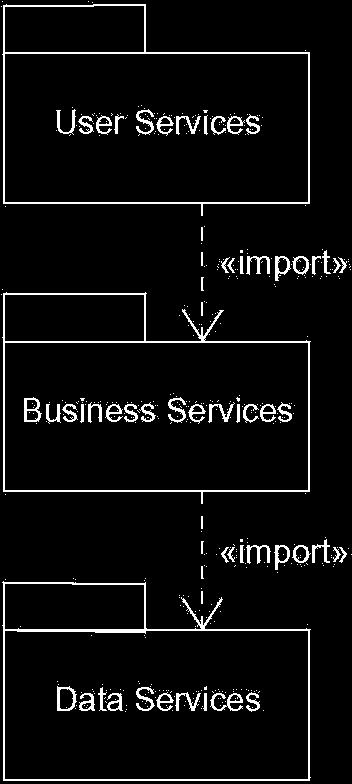
23 Conceptual Model of the UML Grouping Things: Grouping things are the organizational parts of UML models. These are the boxes into which a model can be decomposed. In all, there is one primary kind of grouping thing, namely, packages. Packages: A package is a general-purpose mechanism for organizing elements into groups. Graphically, a package is rendered as a tabbed folder, usually including only its name and, sometimes, its contents Figure: Packages 23
24 Language What is the UML? UML is primarily a graphical language that follows a precise syntax. UML 2 is the most recent version UML is standardized. Its content is controlled by the Object Management Group (OMG), a consortium of companies
25 Conceptual Model of the UML Annotational Things: Annotational things are the explanatory parts of UML models. These are the comments you may apply to describe, illuminate, and remark about any element in a model. There is one primary kind of annotation thing, called a note. A note is simply a symbol for rendering constraints and comments attached to an element or a collection of elements. Figure 2-11 Notes 25
26 How We Got to the UML OO modeling languages made their appearance in the late 70 s. Smalltalk was the first widely used OO language. As the usefulness of OO programming became undeniable, more OO modeling languages began to appear. By the start of the 90 s there was a flood of modeling languages, each with its own strengths and weaknesses
27 How We Got to the UML In 1994 the UML effort officially began as a collaborative effort between Booch and Rumbaugh. Jacobson was soon after included in the effort. The goal of UML is to be a comprehensive modeling language (all things to all people) that will facilitate communication between all members of the development effort
28 UML Diagrams UML 2 supports 13 different types of diagrams Each diagram may be expressed with varying degrees of detail Not all diagrams need be used to model a SW system The UML does not offer an opinion as to which diagrams would be most helpful for a particular type of project 28 28
29 UML Diagrams 29 29
30 What is Legal UML? Even though UML is standardized by the OMG developers will take liberties with syntax. These liberties have a way of becoming standard conventions in later releases of the language. The same holds true for natural languages
31 The UML is not Enough Even if the UML is your primary modeling language, don t hesitate to use other diagrams to model your design
32 Architecture Architecture refers to the different perspectives from which a complex system can be viewed. The architecture of a software-intensive system is best described by five interlocking views: Use case view: system as seen by users, analysts and testers. Design view: classes, interfaces and collaborations that make up the system. Process view: active classes (threads). Implementation view: files that comprise the system. Deployment view: nodes on which SW resides
33 Software Development Life Cycle UML is involved in each phase of the software development life cycle. The UML development process is Use case driven Architecture-centric Iterative and incremental 33 33
34 UNIT-II Basic structural modeling Advanced structural modeling Class and object diagram 34
35 Classes CLASSES A Class is a description of set of objects that share same attributes, operations, relationships and semantics. Name Every class must have a name that distinguishes it from other classes. Business rules::fraudage nt Temperature sensor Customer wall
36 Attributes -an attribute is a named property of a class that describes range of values that instances of the property may hold. Eg: Custom Name er Address Phone Birthdat e Attributes wall Height:float Width :float Thickness:float Isloadbearing :boolean=false Attributes and their classes
37 Operations -An operation is the implementation of a service that can be requested from any object of the class to affect behavior. Rectangle Temperatu re sensor Add() Grow() Move() Isempty() Eg operation
38 Organizing attributes and relationships -To better organize long lists of attributes and operations you prefix each group with descriptive category by using stereotypes. Fraud agent <<constructo r>> New() New(p:policy ) <<process>> Process(o:or der)
39 FraudAgent Responsibili ties -determine a risk of customer order -handle customer specific Responsibilities -a responsibility is a contract or an obligation of a class. -when you create a class you are making a statement that all objects of that class have the same kind of state and behaviour.
40 Common modeling techniques -Modeling the vocabulary of a system To model the vocabulary of a system 1) Identify those things that users to describe the problem.use crc cards and usecase based analysis to help find these abstractions. Custom Name er Addres s Phone BirthDa te Transacti on Action Commit() Rollback( ) Wassucc essfull()
41 Modeling the vocabulary of a system contd. 2)For each abstraction, identify a set of responsibilities. Make sure that each class is crisply defined and that there is a good balance of responsibilities among all your classes. 3)Provide the attributes and operations that are needed to carry out these responsibilities for each class
42 Modeling the Distribution of responsibilities in a System To model the distribution of responsibilities in a System 1)Identify a set of classes that work together closely to carryout some behavior. Model Responsibili ties manage the state of the models View Responsibili ties Render the model on the screen Manage movement and resizing of the view
43 Modeling the Distribution of responsibilities in a System contd 2)Identify a set of responsibilities for each of these classes. 3)Look at this set of classes as a whole, split classes that have too many responsibilities into smaller abstractions, collapse tiny classes that have trivial responsibilities into larger ones, and reallocate responsibilities so that each abstraction reasonably stands on its own. 4)Consider the ways in which those classes collaborate with one another, and redistribute their responsibilities accordingly so that no class within a collaboration does too much or too little.
44 Modeling Non software things 1)Model the thing you are abstracting as a class. 2)If you want to distinguish these things from the uml defined building blocks, create new building block by using stereotype to specify these new semantics and to give a distinctive Visual cue. Accounts receivable Agent Robot Processorder() Changeorder() Status()
45 Modeling Nonsoftware things contd 3) If the thing you are modeling is some kind of hardware that itself contains software, consider modeling it as a kind of node, as well, so that you can further expand on its structure.
46 <<Type>> Int {values range from -2**31-1 to +2**31} <<Enume ration>> Boolean False True <<Enume ration>> status Idle Working error
47 Modeling Primitive Types contd 2) If you need to specify the range of values associated with this type, use constraints.
48 Relationships A relationship is a connection among things. In object-oriented modeling, the three most important relationships are dependencies, generalizations, and associations. Graphically, a relationship is rendered as a path, with different kinds of lines used to distinguish the kinds of relationships. 48
49 Relationships cont.. Dependency A dependency is a using relationship that states that a change in specification of one thing (for example, class Event) may affect another thing that uses it (for example, class Window), but not necessarily the reverse. Graphically, a dependency is rendered as a dashed directed line
50 Generalization -A generalization is a relationship between a general thing (called the super class or parent)and a more specific kind of that thing (called the subclass or child). -Generalization is sometimes called an "is-a-kind-of" relationship: one thing (like the class BayWindow) isa-kind-of a more general thing (for example, the class Window).
51
52 Association -An association is a structural relationship that specifies that objects of one thing are connected to objects of another. Given an association connecting two classes, you can navigate from an object of one class to an object of the other class, and vice versa. -An association that connects exactly two classes is called a binary association. Although it's not as common, you can have associations that connect more than two classes; these are called n-ary associations. Graphically, an association is rendered as a solid line connecting the same or different classes. Use associations when you want to show structural relationships.
53 Association contd There are four adornments that apply to associations Name - An association can have a name, and you use that name to describe the nature of the relationship. So that there is no ambiguity about its meaning, you can give a direction to the name by providing a direction triangle that points in the direction you intend to read the name, as shown in Figure
54 Association
55 Multiplicity -An association represents a structural relationship among objects. In many modeling situations, it's important for you to state how many objects may be connected across an instance of an association. - This "how many" is called the multiplicity of an association's role, and is written as an expression that evaluates to a range of values or an explicit value as in Figure
56 Aggregation -A plain association between two classes represents a structural relationship between peers, meaning that both classes are conceptually at the same level, no one more important than the other. Sometimes, you will want to model a "whole/part" relationship, in which one class represents a larger thing (the "whole"), which consists of smaller things (the "parts"). This kind of relationship is called aggregation, which represents a "has-a" relationship,
57 Aggregation contd.
58 Common Modeling Techniques Modeling simple dependencies -To model this using relationship 1) Create a dependency pointing from the class with the operation to the class used as a parameter in the operation.
59 Modeling simple dependencies
60 Modeling Single Inheritance To model inheritance relationships, 1) Given a set of classes, look for responsibilities, attributes, and operations that are common to two or more classes. 2) Elevate these common responsibilities, attributes, and operations to a more general class. If necessary, create a new class to which you can assign these elements (but be careful about introducing too many levels). 3) Specify that the more-specific classes inherit from the more-general class by placing a generalization relationship that is drawn from each specialized class to its more-general parent.

61 Modeling Single Inheritance
62 Modeling Structural Relationships To model structural relationships, 1)For each pair of classes, if you need to navigate from objects of one to objects of another, specify an association between the two. This is a data-driven view of associations. 2) For each pair of classes, if objects of one class need to interact with objects of the other class other than as parameters to an operation, specify an association between the two. This is more of a behavior-driven view of associations.
63 Modeling Structural Relationships contd. 3) For each of these associations, specify a multiplicity (especially when the multiplicity is not *, which is the default), as well as role names (especially if it helps to explain the model). 4) If one of the classes in an association is structurally or organizationally a whole compared with the classes at the other end that look like parts, mark this as an aggregation by adorning the association at the end near the whole
64 Modeling Structural Relationships contd.. A note is a graphical symbol for rendering constraints or comments attached to an element or a collection of elements. Graphically, a note is rendered as a rectangle with a dogeared corner, together with a textual or graphical comment. A stereotype is an extension of the vocabulary of the UML, allowing you to create new kinds of building blocks similar to existing ones but specific to your problem. Graphically, a stereotype is rendered as a name enclosed by guillemets and placed above the name of another element. As an option, the stereotyped element may be rendered by using a new icon associated with that stereotype.
65 Modeling Structural Relationships contd. A tagged value is an extension of the properties of a UML element, allowing you to create new information in that element's specification. Graphically, a tagged value is rendered as a string enclosed by brackets and placed below the name of another element. A constraint is an extension of the semantics of a UML element, allowing you to add new rules or to modify existing ones. Graphically, a constraint is rendered as a string enclosed by brackets and placed near the associated element or connected to that element or elements by dependency relationships. As an alternative, you can render a constraint in a note.
66 Modeling Structural Relationships Notes contd. A note that renders a comment has no semantic impact, meaning that its contents do not alter the meaning of the model to which it is attached. This is why notes are used to specify things like requirements, observations, reviews, and explanations, in addition to rendering constraints.
67 Other Adornments -Adornments are textual or graphical items that are added to an element's basic notation and are used to visualize details from the element's specification. - For example, the basic notation for an association is a line, but this may be adorned with such details as the role and multiplicity of each end.
68 Tagged Values - a tagged value is rendered as a string enclosed by brackets and placed below the name of another element. That string includes a name (the tag), a separator (the symbol =), and a value (of the tag). You can specify just the value if its meaning is unambiguous, such as when the value is the name of enumeration

69 Tagged Values
70 Documentation - Specifies a comment, description, or explanation of the element to which it is attached. Common Modeling Techniques Modeling Comments To model a comment 1) Put your comment as text in a note and place it adjacent to the element to which it refers. You can show a more explicit relationship by connecting a note to its elements using a dependency relationship.
71 Modeling Comments 2) Remember that you can hide or make visible the elements of your model as you see fit. This means that you don't have to make your comments visible everywhere the elements to which it is attached are visible. Rather, expose your comments in your diagrams only insofar as you need to communicate that information in that context. 3) If your comment is lengthy or involves something richer than plain text, consider putting your comment in an external document and linking or embedding that document in a note attached to your model. 4) As your model evolves, keep those comments that record significant decisions that cannot be inferred from the model itself, and unless they are of historic interest discard the others.

72 To model a comment
73 Modeling New Building Blocks To model new building blocks, Make sure there's not already a way to express what you want by using basic UML. If you have a common modeling problem, chances are there's already some standard stereotype that will do what you want. 2) If you're convinced there's no other way to express these semantics, identify the primitive thing in the UML that's most like what you want to model (for example, class, interface, component, node, association, and so on) and define a new stereotype for that thing. Remember that you can define hierarchies of stereotypes so that you can have general kinds of stereotypes along with their specializations (but as with any hierarchy, use this sparingly).
74 Modeling New Building Blocks contd 3) Specify the common properties and semantics that go beyond the basic element being stereotyped by defining a set of tagged values and constraints for the stereotype. 4) If you want these stereotype elements to have a distinctive visual cue, define a new icon for the stereotype.
75 Modeling New Building Blocks
76 Modeling New Properties -To model new properties 1) First, make sure there's not already a way to express what you want by using basic UML. If you have a common modeling problem, chances are that there's already some standard tagged value that will do what you want. 2) If you're convinced there's no other way to express these semantics, add this new property to an individual element or a stereotype. The rules of generalization apply tagged values defined for one kind of element apply to its children.
77 Modeling New Properties
78 Modeling New Semantics To model new semantics, 1) First, make sure there's not already a way to express what you want by using basic UML. If you have a common modeling problem, chances are that there's already some standard constraint that will do what you want. 2) If you're convinced there's no other way to express these semantics, write your new semantics as text in a constraint and place it adjacent to the element to which it refers. You can show a more explicit relationship by connecting a constraint to its elements using a dependency relationship. 3) If you need to specify your semantics more precisely and formally, write your new semantics using OCL
79 Modeling New Semantics
80 Diagrams Modeling Different Views of a System To model a system from different views 1 ) Decide which views you need to best express the architecture of your system and to expose the technical risks to your project. The five views of an architecture described earlier are a good starting point. 2) For each of these views, decide which artifacts you need to create to capture the essential details of that view. For the most part, these artifacts will consist of various UML diagrams.
81 Modeling Different Views of a System contd 3)As part of your process planning, decide which of these diagrams you'll want to put under some sort of formal or semi-formal control. These are the diagrams for which you'll want to schedule reviews and to preserve as documentation for the project. 4) Allow room for diagrams that are thrown away. Such transitory diagrams are still useful for exploring the implications of your decisions and for experimenting with changes.
82 Modeling Different Views of a System -Use case view Use case diagrams Activity diagrams (for behavioral modeling) - Design view Class diagrams (for structural modeling) Interaction diagrams (for behavioral modeling) Statechart diagrams (for behavioral modeling) -Process view Class diagrams (for structural modeling) Interaction diagrams (for behavioral modeling) -Implementation view Component diagram -Deployment view Deployment diagrams
83 Modeling Different Levels of Abstraction Consider the needs of your readers, and start with a given model. If your reader is using the model to construct an implementation, she'll need diagrams that are at a lower level of abstraction, which means that they'll need to reveal a lot of detail. If she is using the model to present a conceptual model to an end user, she'll need diagrams that are at a higher level of abstraction, which means that they'll hide a lot of detail. Depending on where you land in this spectrum of lowto-high levels of abstraction, create a diagram at the right level of abstraction by hiding or revealing the following four categories of things from your model
84 Building blocks and relationships: Hide those that are not relevant to the intent of your diagram or the needs of your reader. Adornments: Reveal only the adornments of these building blocks and relationships that are essential to understanding your intent. Flow: In the context of behavioral diagrams, expand only those messages or transitions that are essential to understanding your intent. Stereotypes: In the context of stereotypes used to classify lists of things, such as attributes and operations, reveal only those stereotyped items that are essential to understanding your intent.
85 Modeling Different Levels of Abstraction - To model a system at different levels of abstraction by creating models at different levels of abstraction Consider the needs of your readers and decide on the level of abstraction that each should view, forming a separate model for each level. In general, populate your models that are at a high level of abstraction with simple abstractions and your models that are at a low level of abstraction with detailed abstractions. Establish trace dependencies among the related elements of different models.
86 there are four common situations you'll encounter when modeling a system at different levels of abstraction: Use cases and their realization: Use cases in a use case model will trace to collaborations in a design model. Collaborations and their realization: Collaborations will trace to a society of classes that work together to carry out the collaboration. Components and their design: Components in an implementation model will trace to the elements in a design model. Nodes and their components: Nodes in a deployment model will trace to components in an implementation model

87 Figure Interaction Diagram at a High Level of Abstraction 87
88 Modeling Different Levels of Abstraction Figure Interaction at a Low Level of Abstraction
89 Modeling Complex Views To model complex views, First, convince yourself there's no meaningful way to present this information at a higher level of abstraction, perhaps eliding some parts of the diagram and retaining the detail in other parts. If you've hidden as much detail as you can and your diagram is still complex, consider grouping some of the elements in packages or in higher level collaborations, then render only those packages or collaborations in your diagram.
90 Modeling Complex Views contd If your diagram is still complex, use notes and color as visual cues to draw the reader's attention to the points you want to make. If your diagram is still complex, print it in its entire and hang it on a convenient large wall. You lose the interactivity an online version of the diagram brings, but you can step back from the diagram and study it for common patterns.
91 Advanced Classes A classifier is a mechanism that describes structural and behavioral features. Classifiers include classes, interfaces, data types, signals, components, nodes, use cases, and subsystems. The UML provides a number of other kinds of classifiers to help you model. Interface A collection of operations that are used to specify a service of a class or a component Data type A type whose values have no identity, including primitive built-in types (such as numbers and strings), as well as enumeration types (such as Boolean)
92 Signal The specification of an asynchronous stimulus communicated between instances component A physical and replaceable part of a system that conforms to and provides the realization of a set of interfaces Node A physical element that exists at run time and that represents a computational resource, generally having at least some memory and often processing capability Use case A description of a set of a sequence of actions, including variants, that a system performs that yields an observable result of value to a particular actor Subsystem A grouping of elements of which some constitute a specification of the behavior offered by the other contained elements
93 Visibility Advanced Classes contd - UML, you can specify any of three levels of visibility. 1. public Any outside classifier with visibility to the given classifier can use the feature specified by prepending the symbol protected Any descendant of the classifier can use the feature; specified by prepending the symbol #. 3. private Only the classifier itself can use the feature; specified by prepending the symbol.
94 Scope 1. instance Each instance of the classifier holds its own value for the feature. 2. classifier There is just one value of the feature for all instances of the classifier.

95 Multiplicity - The number of instances a class may have is called its multiplicity. Multiplicity is a specification of the range of allowable cardinalities an entity may assume.
96 Attributes In its full form, the syntax of an attribute in the UML is [visibility] name [multiplicity] [: type] [= initial-value] [{property-string}]
97 There are three defined properties that you can use with attributes. 1.changeable 2. addonly 3. frozen Operations In its full form, the syntax of an operation in the UML is [visibility] name [(parameter-list)] [: return-type] [{propertystring}]
98 In an operation's signature, you may provide zero or more parameters, each of which follows the syntax [direction] name : type [= default-value] Direction may be any of the following values 1) in 2) out 3) inout -there are four defined properties that you can use with operations. 1)IsQuery 2)Sequential 3)Guarded 4)Concurrent
99 Template Classes - A template is a parameterized element. In such languages as C++ and Ada, you can write template classes, each of which defines a family of classes (you can also write template functions, each of which defines a family of functions). template<class Item, class Value, int Buckets> class Map { public: virtual Boolean bind(const Item&, constvalue&); virtual Boolean isbound(const Item&) const;... };
100 Standard Elements The UML defines four standard stereotypes that apply to classes. 1)Metaclass 2)Powertype 3)Streotype 4)Utility
101 Modeling semantics of class 1) Specify the responsibilities of the class. A responsibility is a contract or obligation of a type or class and is rendered in a note (stereotyped as responsibility) attached to the class, or in an extra compartment in the class icon. 2) Specify the semantics of the class as a whole using structured text, rendered in a note (stereotyped as semantics) attached to the class.
102 Modeling semantics of class contd 3) Specify the body of each method using structured text or a programming language, rendered in a note attached to the operation by a dependency relationship. 4) Specify the pre- and post conditions of each operation, plus the invariants of the class as a whole, using structured text. These elements are rendered in notes (stereotyped as precondition, post condition, and invariant) attached to the operation or class by a dependency relationship.
103 Modeling semantics of class contd 5) Specify a state machine for the class. A state machine is a behavior that specifies the sequences of states an object goes through during its lifetime in response to events, together with its responses to those events. 6) Specify a collaboration that represents the class. A collaboration is a society of roles and other elements that work together to provide some cooperative behavior that's bigger than the sum of all the elements. A collaboration has a structural part, as well as a dynamic part, so you can use collaborations to specify all dimensions of a class's semantics.
104 Advanced Relationships -A relationship is a connection among things. In objectoriented modeling, the four most important relationships are dependencies, generalizations, associations, and realizations. -Graphically, a relationship is rendered as a path, with different kinds of lines used to distinguish the different relationships.
105 Advanced Relationships contd Dependency -there are eight stereotypes that apply to dependency relationships. 1.Bind 2.Derive 3.Friend 4.Instanceof 5.Instantiate 6.Powertype 7.Refine
106 Advanced Relationships contd There are two stereotypes that apply to dependency relationships among packages. 1)access 2)Import There are two stereotypes that apply to dependency relationships among usecases. 1)Extend 2) Include
107 Advanced Relationships contd three stereotypes when modeling interactions among objects. 1)Become 2)Call 3)Copy One stereotype you'll encounter in the context of state machines is 1)Send 2)Trace
108 Advanced Relationships contd Generalization A generalization is a relationship between a general thing (called the superclass or parent) and a more specific kind of that thing (called the subclass or child). The four constraints that may be applied to generalization relationships. 1.Complete 2.Incomplete 3.Disjoint 4.Overlapping
109 Navigation Association - Given a plain, unadorned association between two classes, such as Book and Library, it's possible to navigate from objects of one kind to objects of the other kind.
110 Visibility - Given an association between two classes, objects of one class can see and navigate to objects of the other, unless otherwise restricted by an explicit statement of navigation
111 Qualification
112 Interface Specifier
113 Composition Aggregation turns out to be a simple concept with some fairly deep semantics. Simple aggregation is entirely conceptual and does nothing more than distinguish a "whole" from a "part." Simple aggregation does not change the meaning of navigation across the association between the whole and its parts, nor does it link the lifetimes of the whole and its parts
114 Composition
115 1.Implicit 2.Ordered 3.Changable 4.Addonly 5.Frozen Realization Constraints A realization is a semantic relationship between classifiers in which one classifier specifies a contract that another classifier guarantees to carry out.
116 Next, identify opportunities for generalization/specialization relationships; use multiple inheritance sparingly. Common Modeling Techniques Modeling Webs of Relationships Don't begin in isolation. Apply use cases and scenarios to drive your discovery of the relationships among a set of abstractions. In general, start by modeling the structural relationships that are present. These reflect the static view of the system and are therefore fairly tangible.
117 Remember that it is both undesirable and unnecessary to model all relationships among a set of abstractions in a single diagram or view. Rather, build up your system's relationships by considering different views on the system. Highlight interesting sets of relationships in individual diagrams. Modeling Webs of Relationships Only after completing the preceding steps should you look for dependencies; they generally represent moresubtle forms of semantic connection. For each kind of relationship, start with its basic form and apply advanced features only as absolutely necessary to express your intent.
118 An interface is a collection of operations that are used to specify a service of a class or a component. Names An interface name must be unique within its enclosing package. Operations An interface is a named collection of operations used to specify a service of a class or of a component. Relationships Like a class, an interface may participate in generalization, association, and dependency relationships.
119 Types and Roles
120 Common Modeling Techniques Modeling the Seams in a Systemeling the Seams in a System Within the collection of classes and components in your system, draw a line around those that tend to be tightly coupled relative to other sets of classes and components. Refine your grouping by considering the impact of change. Classes or components that tend to change together should be grouped together as collaborations.
121 Modeling the Seams in a Systemeling the Seams in a System Consider the operations and the signals that cross these boundaries, from instances of one set of classes or components to instances of other sets of classes and components. - Package logically related sets of these operations and signals as interfaces. For each such collaboration in your system, identify the interfaces it relies on (imports) and those it provides to others (exports). You model the importing of interfaces by dependency relationships, and you model the exporting of interfaces by realization relationships. For each such interface in your system, document its dynamics by using pre- and postconditions for each operation, and use cases and state machines for the interface as a whole.
122 Modeling Static and Dynamic Types To model a dynamic type Specify the different possible types of that object by rendering each type as a class stereotyped as type (if the abstraction requires structure and behavior) or as interface (if the abstraction requires only behavior). Model all the roles the class of the object may take on at any point in time. You can do so in two ways: First, in a class diagram, explicitly type each role that the class plays in its association with other classes. Doing this specifies the face instances of that class put on in the context of the associated object. Second, also in a class diagram, specify the class-totype relationships using generalization.
123 To model a dynamic type In an interaction diagram, properly render each instance of the dynamically typed class. Display the role of the instance in brackets below the object's name. To show the change in role of an object, render the object once for each role it plays in the interaction, and connect these objects with a message stereotyped as become.
124 To model a dynamic type contd

125 Packages Names A package name must be unique within its enclosing package.
126 Packages contd Owned Elements -A package may own other elements, including classes, interfaces, components, nodes, collaborations, use cases, diagrams, and even other packages. Visibility -You can control the visibility of the elements owned by a package just as you can control the visibility of the attributes and operations owned by a class
127 Packages contd Importing and Exporting Suppose you have two classes named A and B sitting side by side. Because they are peers, A can see B and B can see A, so both can depend on the other. Just two classes makes for a trivial system, so you really don't need any kind of packaging.
128 Importing and Exporting
129 Generalization There are two kinds of relationships you can have between packages: import and access dependencies, used to import into one package elements exported from another, and generalizations, used to specify families of packages. Standard Elements 1.Facade 2.Framework 3.Stub 4.Subsytem 5.System
130 Common Modeling Techniques Modeling Groups of Elements To model groups of elements, Scan the modeling elements in a particular architectural view and look for clumps defined by elements that are conceptually or semantically close to one another. Surround each of these clumps in a package.
131 Modeling Groups of Elements contd. For each package, distinguish which elements should be accessible outside the package. Mark them public, and all others protected or private. When in doubt, hide the element. Explicitly connect packages that build on others via import dependencies. In the case of families of packages, connect specialized packages to their more general part via generalizations.

132 Modeling Groups of Elements
133 Modeling Architectural Views To model architectural views, Identify the set of architectural views that are significant in the context of your problem. In practice, this typically includes a design view, a process view, an implementation view, a deployment view, and a use case view. Place the elements (and diagrams) that are necessary and sufficient to visualize, specify, construct, and document the semantics of each view into the appropriate package
134 Modeling Architectural Views As necessary, further group these elements into their own packages. There will typically be dependencies across the elements in different views. So, in general, let each view at the top of a system be open to all others at that level
135 CLASS AND OBJECT DIAGRAM
136 Class diagram Class diagram It s a diagram that shows set of classes,interfaces,collaboration and either relationships. Common properties It shows the same common properties as all other diagrams. Contents Class diagram contain the following things 1. Classes 2. Interfaces 3. Collaboration 4. Dependency,Generalization, association
137 Common modeling techniques Modeling simple collaboration To model a collaboration. 1. Identify the mechanism you want to model. 2. For each mechanism identify the classes,interfaces and collaboration. 3. Use scenarios to walk through these things. 4. Be sure to populate these elements with their contents.
138 Modeling a logical database schema To model a schema 1. Identify those classes in the model whose state must transcend the lifetime of their application. 2. Create class diagram that contain these classes and mark them as persistent. 3. Explain structural details of these classes. 4. Watch for common pattern that complicate physical database design. 5. Consider the behavior of these classes by expending operations. 6. Use tools to transform logical design to physical design.
139 Modeling a Logical Database name : Name address : String School { persistent} Department { persistent} name : Name 0..1 phone : Number addstudent() removestudent() getstudent() getallstudents() adddepartment() removedepartment() getdepartment() 1..* addinstructor() removeinstructor() getinstructor() getallinstructors() 1..* 1..* getalldepartments() 1..* * 1..* 1..* 0..1 chairperson Student Course Instructor { persistent} { persistent} { persistent} name : Name studentid : Number * * name : Name courseid : Number * 1..* name : Name 139
140 Forward and Reverse Engineering Forward Engineering - It is the process of transforming a model intocode through a mapping to an implementation language. To forward engineer a class diagram 1) Identify the rules for mapping to your implentation language. 2) Depending upon the semsntics of the language you have to constrain. 3) Use tagged values to specify your tagged values. 4) Use tools to forward engineer your models.
141 Reverse Engineering -transforming code to uml model. To reverse engineer a class diagram 1) Identify the rules for mapping from your language. 2) Use tools point to code you would like to reverse engineer. 3) Use tool, create a class diagram by querying the model.
142 Public abstract class EventHandler { EventHandler sucessor; private Integer CurrentEventId; private String source; EventHandler() { } public void handlerequest(){ } }
143 Object Diagram Object diagram -it is a diagram that shows set of objects and their relationships at a point in time. Contents : -objects -links Object diagram contains notes and constraints.
144 Modeling object structures To model object structures 1) Identify the mechanism you would like to model. 2) For each mechanism,identify classes,interfaces,other elements. 3) Consider one scenario that work through this mechanism. 4) Expose the state and atrribute value of each such object to understand. 5) Similarly expose the links,instances,associationns among them
145
146 Forward and Reverse Engineer To reverse engineer an object diagram 1) Choose the target you want to reverse engineer. 2) Use tool or simply walkthrough a scenario. 3) Identify the set of objects that collaborate in the context. 4) As necessary to understand their semantics expose these objects. 5) Identify links among objects. 6) If your diagrams end up complicated,prune it by eliminating objects that are not germane.
147 UNIT III BASIC BEHAVIOURAL MODELING-I BASIC BEHAVIORAL MODELING -II
148 INTERACTION An interaction is a behavior that comprises a set of messages exchanged among a set of objects within a context to accomplish a purpose. A message is a specification of a communication between objects that conveys information with the expectation that activity will ensue.
149 CONTEXT You'll find interactions in the collaboration of objects that exist in the context of your system or subsystem Object and Roles : The object that participate in an interaction is either concrete or prototypical
150 LINKS A link is a semantic connection among objects. In general, a link is an instance of an association. Following fig. shows, wherever a class has an association to another class, there may be a link between the instances of the two classes; wherever there is a link between two objects, one object can send a message to the other object.
151 LINKS contd
152 Link contd. Association corresponding object is visible by association. self - dispatches of operation. Global represents enclosing scope. Local local scope Parameter parameter visibility.
153 MESSAGE When you pass a message, the action that results is an executable statement that forms an abstraction of a computational procedure. An action may result in a change in state. UML can model several kind of actions: call - invoke an operation return - return a value to the caller send - send signal to an object create - creates an object destroy - destroys an object Following figure shows visual distinction among different kind of messages
154 MESSAGE contd..
155 SEQUENCING When an object passes a message to another object (in effect, delegating some action to the receiver), the receiving object might in turn send a message to another object, which might send a message to yet a different object, and so on. This stream of messages forms a sequence.
156 Procedural Sequence
157 Flat Sequence
158 Creation,Modification and destruction : To specify if an object or link enters and/or leaves during an interaction you can attach one of the following constraints to the element: New link is created. Destroyed link is destroyed. Transient link is created during execution of enclosing interaction.
159 Modeling a flow control To model a flow of control Set the context for the interaction, whether it is the system as a whole, a class, or an individual operation. Set the stage for the interaction by identifying which objects play a role; set their initial properties, including their attribute values, state, and role. If your model emphasizes the structural organization of these objects, identify the links that connect them, relevant to the paths of communication that take place in this interaction. Specify the nature of the links using the UML's standard stereotypes and constraints, as necessary.
160 Modeling a flow control contd.. In time order, specify the messages that pass from object to object. As necessary, distinguish the different kinds of messages; include parameters and return values to convey the necessary detail of this interaction. Also to convey the necessary detail of this interaction, adorn each object at every moment in time with its state and role.
161 Eg. Flow of control by time
162 Eg. Flow of control by organization
163 INTERACTION DIAGRAMS Interaction diagrams are not only important for modeling the dynamic aspects of a system, but also for constructing executable systems through forward and reverse engineering. A sequence diagram is an interaction diagram that emphasizes the time ordering of messages. A collaboration diagram is an interaction diagram that emphasizes the structural organization of the objects that send and receive messages.
164 INTERACTION DIAGRAMS contd Interaction diagrams commonly contain Objects Links Messages
165 SEQUENCE DIAGRAM
166 COLLABORATION DIAGRAM
167 Modeling flow control by Time ordering Set the context for the interaction, whether it is a system, subsystem, operation, or class, or one scenario of a use case or collaboration. Set the stage for the interaction by identifying which objects play a role in the interaction. Lay them out on the sequence diagram from left to right, placing the more important objects to the left and their neighboring objects to the right. Set the lifeline for each object. In most cases, objects will persist through the entire interaction. For those objects that are created and destroyed during the interaction, set their lifelines, as appropriate, and explicitly indicate their birth and death with appropriately stereotyped messages
168 Modeling flow control by Time ordering contd.. Starting with the message that initiates this interaction, lay out each subsequent message from top to bottom between the lifelines, showing each message's properties (such as its parameters), as necessary to explain the semantics of the interaction. If you need to visualize the nesting of messages or the points in time when actual computation is taking place, adorn each object's lifeline with its focus of control. If you need to specify time or space constraints, adorn each message with a timing mark and attach suitable time or space constraints. If you need to specify this flow of control more formally, attach pre- and postconditions to each message.
169 Eg. Modeling Flows of Control by Time Ordering
170 Modeling Flows of control by organization Set the context for the interaction, whether it is a system, subsystem, operation, or class, or one scenario of a use case or collaboration. Set the stage for the interaction by identifying which objects play a role in the interaction. Lay them out on the collaboration diagram as vertices in a graph, placing the more important objects in the center of the diagram and their neighboring objects to the outside. Set the initial properties of each of these objects. If the attribute values, tagged values, state, or role of any object changes in significant ways over the duration of the interaction, place a duplicate object on the diagram, update it with these new values, and connect them by a message stereotyped as become or copy (with a suitable sequence number).
171 Modeling Flows of control by organization contd.. Specify the links among these objects, along which messages may pass. Lay out the association links first; these are the most important ones, because they represent structural connections. Lay out other links next, and adorn them with suitable path stereotypes (such as global and local) to explicitly specify how these objects are related to one another. Starting with the message that initiates this interaction, attach each subsequent message to the appropriate link, setting its sequence number, as appropriate. Show nesting by using Dewey decimal numbering.
172 Modeling Flows of control by organization contd.. If you need to specify time or space constraints, adorn each message with a timing mark and attach suitable time or space constraints. If you need to specify this flow of control more formally, attach pre- and post conditions to each message.
173 Modeling Flows of control by organization
174 BASIC BEHAVIORAL MODELING -II
175 Use Cases A use case is a description of a set of sequences of actions, including variants, that a system performs to yield an observable result of value to an actor. Graphically, a use case is rendered as an ellipse. Names Every use case must have a name that distinguishes it from other use cases. A name is a textual string. That name alone is known as a simple name; a path name is the use case name prefixed by the name of the package in which that use case lives. A use case is typically drawn showing only its name

176 Use Cases contd..
177 Note Use Cases contd.. A use case name may be text consisting of any number of letters, numbers, and most punctuation marks (except for marks such as the colon, which is used to separate a class name and the name of its enclosing package) and may continue over several lines Use Cases and Actors An actor represents a coherent set of roles that users of use cases play when interacting with these use cases.

178 Actors contd
179 Use Cases and Flow of Events A use case describes what a system (or a subsystem, class, or interface) does but it does not specify how it does it. When you model, it's important that you keep clear the separation of concerns between this outside and inside view. Main flow of events: The use case starts when the system prompts the Customer for a PIN number. The Customer can now enter a PIN number via the keypad. The Customer commits the entry by pressing the Enter button. The system then checks this PIN number to see if it is valid. If the PIN number is valid, the system acknowledges the entry, thus ending the use case. Exceptional flow of events: The Customer can cancel a transaction at any time by pressing the Cancel button, thus restarting the use case. No changes are made to the Customer's account.
180 Exceptional flow of events: The Customer can clear a PIN number anytime before committing it and reenter a new PIN number. Exceptional flow of events: If the Customer enters an invalid PIN number, the use case restarts. If this happens three times in a row, the system cancels the entire transaction, preventing the Customer from interacting with the ATM for 60 seconds.
181 A use case captures the intended behavior of the system (or subsystem, class, or interface) you are developing, without having to specify how that behavior is implemented. That's an important separation because the analysis of a system (which specifies behavior) should, as much as possible, not be influenced by implementation issues (which specify how that behavior is to be carried out) Use Cases and Scenarios Scenarios are to use cases as instances are to classes, meaning that a scenario is basically one instance of a use case. Use Cases and Collaborations
182 Use Cases and Collaborations
183 Organizing Use Cases You can also organize use cases by specifying generalization, include, and extend relationships among them. You apply these relationships in order to factor common behavior (by pulling such behavior from other use cases that it includes) and in order to factor variants (by pushing such behavior into other use cases that extend it). An include relationship between use cases means that the base use case explicitly incorporates the behavior of another use case at a location specified in the base. An extend relationship between use cases means that the base use case implicitly incorporates the behavior of another use case at a location specified indirectly by the extending use case
184 Common Modeling Techniques Modeling the Behavior of an Element To model the behavior of an element, Identify the actors that interact with the element. Candidate actors include groups that require certain behavior to perform their tasks or that are needed directly or indirectly to perform the element's functions. Organize actors by identifying general and more specialized roles. For each actor, consider the primary ways in which that actor interacts with the element. Consider also interactions that change the state of the element or its environment or that involve a response to some event. Consider also the exceptional ways in which each actor interacts with the element. Organize these behaviors as use cases, applying include and extend relationships to factor common behavior and distinguish

185 Modeling the Behavior of an Element
186 Use Case Diagrams A use case diagram is a diagram that shows a set of use cases and actors and their relationships. Common Properties A use case diagram is just a special kind of diagram and shares the same common properties as do all other diagrams a name and graphical contents that are a projection into a model. What distinguishes a use case diagram from all other kinds of diagrams is its particular content. Contents Use case diagrams commonly contain Use cases Actors Dependency, generalization, and association relationships
187 Common Modeling Techniques Modeling the Context of a System To model the context of a system, Identify the actors that surround the system by considering which groups require help from the system to perform their tasks; which groups are needed to execute the system's functions; which groups interact with external hardware or other software systems; and which groups perform secondary functions for administration and maintenance. Organize actors that are similar to one another in a generalization/specialization hierarchy.
188 Modeling the Context of a System contd.. Where it aids understandability, provide a stereotype for each such actor. Populate a use case diagram with these actors and specify the paths of communication from each actor to the system's use cases.
189 Modeling the Context of a System contd..
190 Modeling the Requirements of a System To model the requirements of a system, Establish the context of the system by identifying the actors that surround it. For each actor, consider the behavior that each expects or requires the system to provide. Name these common behaviors as use cases. Factor common behavior into new use cases that are used by others; factor variant behavior into new use cases that extend more main line flows. Model these use cases, actors, and their relationships in a use case diagram. Adorn these use cases with notes that assert nonfunctional requirements; you may have to attach some of these to the whole system.

191 Modeling the Requirements of a System
192 Forward and Reverse Engineering Forward engineering is the process of transforming a model into code through a mapping to an implementation language To forward engineer a use case diagram, For each use case in the diagram, identify its flow of events and its exceptional flow of events. Depending on how deeply you choose to test, generate a test script for each flow, using the flow's preconditions as the test's initial state and its postconditions as its success criteria. As necessary, generate test scaffolding to represent each actor that interacts with the use case. Actors that push information to the element or are acted on by the element may either be simulated or substituted by its real-world equivalent. Use tools to run these tests each time you release the element to which the use case diagram applies.
193 To reverse engineer a use case diagram, Identify each actor that interacts with the system. For each actor, consider the manner in which that actor interacts with the system, changes the state of the system or its environment, or responds to some event. Trace the flow of events in the executable system relative to each actor. Start with primary flows and only later consider alternative paths. Cluster related flows by declaring a corresponding use case. Consider modeling variants using extend relationships, and consider modeling common flows by applying include relationships. Render these actors and use cases in a use case diagram, and establish their relationships.
194 Activity Diagrams An activity diagram shows the flow from activity to activity. An is an ongoing nonatomic execution within a state machine. Contents Activity states and action states Transitions Objects
195 Action States and Activity States In the flow of control modeled by an activity diagram, things happen. You might evaluate some expression that sets the value of an attribute or that returns some value. Alternately, you might call an operation on an object, send a signal to an object, or even create or destroy an object. These executable, atomic computations are called action states because they are states of the system, each representing the execution of an action.
196 Action States and Activity States contd.
197 Transitions Triggerless transitions may have guard conditions, meaning that such a transition will fire only if that condition is met; guard conditions.

198 Branching Branches are a notational convenience, semantically equivalent to multiple transitions with guards.
199 Forking and Joining As the figure also shows, a join represents the synchronization of two or more concurrent flows of control. A join may have two or more incoming transitions and one outgoing transition. Above the join, the activities associated with each of these paths continues in parallel. At the join, the concurrent flows synchronize, meaning that each waits until all incoming flows have reached the join, at which point one flow of control continues on below the join. when you are modeling workflows of business processes you might encounter flows that are concurrent. In the UML, you use a synchronization bar to specify the forking and joining of these parallel flows of control. A synchronization bar is rendered as a thick horizontal or vertical line.
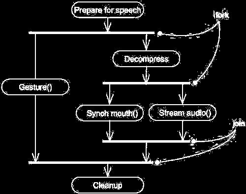
200
201 Swimlanes In the UML, each group is called a swimlane because, visually, each group is divided from its neighbor by a vertical solid line.a swimlane specifies a locus of activities. Each swimlane has a name unique within its diagram. A swimlane really has no deep semantics, except that it may represent some real-world entity. Each swimlane represents a high-level responsibility for part of the overall activity of an activity diagram, and each swimlane may eventually be implemented by one or more classes. In an activity diagram partitioned into swimlanes, every activity belongs to exactly one swimlane, but transitions may cross lanes.

202 Object Flow In addition to showing the flow of an object through an activity diagram, you can also show how its role, state and attribute values change. As shown in the figure, you represent the state of an object by naming its state in brackets below the object's name. Similarly, you can represent the value of an object's attributes by rendering them in a compartment below the object's name.
203 Common Modeling Techniques Modeling a Workflow To model a workflow, Establish a focus for the workflow. For nontrivial systems, it's impossible to show all interesting workflows in one diagram. Select the business objects that have the high-level responsibilities for parts of the overall workflow. These may be real things from the vocabulary of the system, or they may be more abstract. In either case, create a swimlane for each important business object. Identify the preconditions of the workflow's initial state and the postconditions of the workflow's final state. This is important in helping you model the boundaries of the workflow. Beginning at the workflow's initial state, specify the activities and actions that take place over time and render them in the activity diagram as either activity states or action states.
204 Modeling a Workflow contd.. For complicated actions, or for sets of actions that appear multiple times, collapse these into activity states, and provide a separate activity diagram that expands on each. Render the transitions that connect these activity and action states. Start with the sequential flows in the workflow first, next consider branching, and only then consider forking and joining. If there are important objects that are involved in the workflow, render them in the activity diagram, as well. Show their changing values and state as necessary to communicate the intent of the object flow.
205 Modeling a Workflow contd..
206 Modeling an Operation To model an operation, Collect the abstractions that are involved in this operation. This includes the operation's parameters (including its return type, if any), the attributes of the enclosing class, and certain neighboring classes. Identify the preconditions at the operation's initial state and the postconditions at the operation's final state. Also identify any invariants of the enclosing class that must hold during the execution of the operation. Beginning at the operation's initial state, specify the activities and actions that take place over time and render them in the activity diagram as either activity states or action states.

207 Modeling an Operation contd Use branching as necessary to specify conditional paths and iteration. Only if this operation is owned by an active class, use forking and joining as necessary to specify parallel flows of control.
208 Forward and Reverse Engineering Forward engineering (the creation of code from a model) is possible for activity diagrams, especially if the context of the diagram is an operation. For example, using the previous activity diagram, a forward engineering tool could generate the following C++ code for the operation intersection. Point Line::intersection (l : Line) { if (slope == l.slope) return Point(0,0); int x = (l.delta - delta) / (slope - l.slope); int y = (slope * x) + delta; return Point(x, y); }
209 Forward and Reverse Engineering contd.. Reverse engineering (the creation of a model from code) is also possible for activity diagrams, especially if the context of the code is the body of an operation. In particular, the previous diagram could have been generated from the implementation of the class Line.
210 UNIT-IV Advanced Behavioral Modeling Architectural modeling
211 Events and Signals An event is the specification of a significant occurrence that has a location in time and space. In the context of state machines, an event is an occurrence of a stimulus that can trigger a state transition. A signal is a kind of event that represents the specification of an asynchronous stimulus communicated between instances. 211
212 Event 212
213 Signal 213
214 Terms and Concepts Events may be external or internal. External events are those that pass between the system and its actors. Internal events are those that pass among the objects that live inside the system. An overflow exception is an example of an internal event. 214
215 Call Events Just as a signal event represents the occurrence of a signal, a call event represents the dispatch of an operation. Whereas a signal is an asynchronous event, a call event is, in general, synchronous. This means that when an object invokes an operation on another object that has a state machine, control passes from the sender to the receiver, the transition is triggered by the event. 215
216 Call event 216
217 Time and Change Events A time event is an event that represents the passage of time. In the UML you model a time event by using the keyword after followed by some expression that evaluates to a period of time. A change event is an event that represents a change in state or the satisfaction of some condition. In the UML you model a change event by using the keyword when followed by some Boolean expression 217

218 Time and Change Events 218
219 Sending and Receiving Events Signal events and call events involve at least two objects: the object that sends the signal or invokes the operation, and the object to which the event is directed. Because signals are asynchronous, and because asynchronous calls are themselves signals, the semantics of events interact with the semantics of active objects and passive objects. 219
220 Signals and Active Classes. 220
221 Common Modeling Techniques Modeling a Family of Signals To model a family of signals, Consider all the different kinds of signals to which a given set of active objects may respond. Look for the common kinds of signals and place them in a generalization/specialization hierarchy using inheritance. Look for the opportunity for polymorphism in the state machines of these active objects. 221

222 Modeling Families of Signals 222
223 Modeling Exceptions In the UML, exceptions are kinds of signals, which you model as stereotyped classes. Exceptions may be attached to specification operations. Modeling exceptions is somewhat the inverse of modeling a general family of signals. 223
224 To model exceptions, For each class and interface, and for each operation of such elements, consider the exceptional conditions that may be raised. Arrange these exceptions in a hierarchy. Elevate general ones, lower specialized ones, and introduce intermediate exceptions, as necessary. For each operation, specify the exceptions that it may raise. You can do so explicitly (by showing send dependencies from an operation to its exceptions) or you can put this in the operation's specification. 224
225 Modeling Exceptions 225
226 State Machines A state machine is a behavior that specifies the sequences of states an object goes through during its lifetime in response to events, together with its responses to those events. A state is a condition or situation during the life of an object during which it satisfies some condition, performs some activity, or waits for some event. 226
227 Terms and Concepts A transition is a relationship between two states indicating that an object in the first state will perform certain actions and enter the second state when a specified event occurs and specified conditions are satisfied. An activity is ongoing nonatomic execution within a state machine. An action is an executable atomic computation that results in a change in state of the model or the return of a value. Graphically, a state is rendered as a rectangle with rounded corners. A transition is rendered as a solid directed line 227
228 States A state is a condition or situation during the life of an object during which it satisfies some condition, performs some activity, or waits for some event. An object remains in a state for a finite amount of time. 228
229 States 229
230 Transitions A transition is a relationship between two states indicating that an object in the first state will perform certain actions and enter the second state when a specified event occurs and specified conditions are satisfied. 230
231 Transitions 231
232 Common Modeling Techniques Modeling the Lifetime of an Object To model the lifetime of an object, Set the context for the state machine, whether it is a class, a use case, or the system as a whole. Establish the initial and final states for the object. To guide the rest of your model, possibly state the pre- and postconditions of the initial and final states, respectively. 232
233 Decide on the events to which this object may respond. Starting from the initial state to the final state, lay out the top-level states the object may be in. Connect these states with transitions triggered by the appropriate events. Continue by adding actions to these transitions. Identify any entry or exit actions (especially if you find that the idiom they cover is used in the state machine). 233
234 Expand these states as necessary by using substates. Check that all actions mentioned in the state machine are sustained by the relationships, methods, and operations of the enclosing object. 234


235 Modeling the Lifetime of An Object 235
236 Processes and Threads Terms and Concepts A process is a heavyweight flow that can execute concurrently with other processes. A thread is a lightweight flow that can execute concurrently with other threads within the same process. Processes and threads are rendered as stereotyped active classes (and also appear as sequences in interaction diagrams). 236
237 Flow of Control In a purely sequential system, there is one flow of control. When a sequential program starts, control is rooted at the beginning of the program and operations are dispatched one after another. Even if there are concurrent things happening among the actors outside the system, a sequential program will process only one event at a time, queuing or discarding any concurrent external events. 237
238 Synchronization Visualize for a moment the multiple flows of control that weave through a concurrent system. When a flow passes through an operation, we say that at a given moment, the locus of control is in the operation. If that operation is defined for some class, we can also say that at a given moment, the locus of control is in a specific instance of that class. 238
239 Synchronization 239
240 Common Modeling Techniques Modeling Multiple Flows of Control To model multiple flows of control, Identify the opportunities for concurrent action and reify each flow as an active class. Generalize common sets of active objects into an active class. Capture these static decisions in class diagrams, explicitly highlighting each active class. 240
241 Modeling Flows of Control 241
242 Modeling Interprocess Communication To model interprocess communication, Model the multiple flows of control. Consider which of these active objects represent processes and which represent threads. Model messaging using asynchronous communication. Informally specify the underlying mechanism for communication by using notes, or more formally by using collaborations. 242
243 Modeling Interprocess Communication 243
244 Time and Space Terms and Concepts A time expression is an expression that evaluates to an absolute or relative value of time. A timing constraint is a semantic statement about the relative or absolute value of time. Graphically, a timing constraint is rendered as for any constraint Location is the placement of a component on a node. Graphically, location is rendered as a tagged value 244
245 Time 245
246 Common Modeling Techniques Modeling Timing Constraints To model timing constraints, For each event in an interaction, consider whether it must start at some absolute time. Model that real time property as a timing constraint on the message. For each interesting sequence of messages in an interaction, consider whether there is an associated maximum relative time for that sequence. Model that real time property as a timing constraint on the sequence. For each time critical operation in each class, consider its time complexity. Model those semantics as timing constraints on the operation 246
247 Modeling Timing Constraint 247
248 Modeling the Distribution of Objects To model the distribution of objects, For each interesting class of objects in your system, consider its locality of reference. In other words, consider all its neighbors and their locations. A tightly coupled locality will have neighboring objects close by Next consider patterns of interaction among related sets of objects. Colocate sets of objects that have high degrees of interaction, to reduce the cost of communication. Partition sets of objects that have low degrees of interaction. Next consider the distribution of responsibilities across the system. Redistribute your objects to balance the load of each node. Consider also issues of security, volatility, and quality of service, and redistribute your objects as appropriate. 248
249 Modeling the Distribution of Objects 249
250 Modeling Objects that Migrate To model the migration of objects, Select an underlying mechanism for physically transporting objects across nodes. Render the allocation of an object to a node by explicitly indicating its location as a tagged value. Using the become and copy stereotyped messages, render the allocation of an object to a new node. Consider the issues of synchronization (keeping the state of cloned objects consistent) and identity (preserving the name of the object as it moves). 250
251 Modeling Objects that Migrate 251
252 Statechart Diagrams Terms and Concepts A statechart diagram shows a state machine, emphasizing the flow of control from state to state. A state machine is a behavior that specifies the sequences of states an object goes through during its lifetime in response to events, together with its responses to those events. A state is a condition or situation in the life of an object during which it satisfies some condition, performs some activity, or waits for some event. 252
253 Contents Statechart diagrams commonly contain Simple states and composite states Transitions, including events and actions A statechart diagram is basically a projection of the elements found in a state machine. This means that statechart diagrams may contain branches, forks, joins, action states, activity states, objects, initial states, final states, history states, 253
254 Common Modeling Technique Modeling Reactive Objects To model a reactive object, Choose the context for the state machine, whether it is a class, a use case, or the system as a whole. Choose the initial and final states for the object. To guide the rest of your model, possibly state the pre- and postconditions of the initial and final states, respectively. Decide on the stable states of the object by considering the conditions in which the object may exist for some identifiable period of time. Start with the high-level states of the object and only then consider its possible substates. 254
255 Decide on the meaningful partial ordering of stable states over the lifetime of the object. Decide on the events that may trigger a transition from state to state. Model these events as triggers to transitions that move from one legal ordering of states to another. Attach actions to these transitions (as in a Mealy machine) and/or to these states (as in a Moore machine). Consider ways to simplify your machine by using substates, branches, forks, joins, and history states. 255
256 Modeling Reactive Objects 256
257 Forward and Reverse Engineering Forward engineering(the creation of code from a model) is possible for statechart diagrams, especially if the context of the diagram is a class. 257
258 The forward engineering tool must generate the necessary private attributes and final static constants. Reverse engineering (the creation of a model from code) is theoretically possible, but practically not very useful. The choice of what constitutes a meaningful state is in the eye of the designer. Reverse engineering tools have no capacity for abstraction and therefore cannot automatically produce meaningful statechart diagrams. More interesting than the reverse engineering of a model from code is the animation of a model against the execution of a deployed system. For example, given the previous diagram, a tool could animate the states in the diagram as they were reached in the running system. Similarly, the firing of transitions could be animated, showing the receipt of events and the resulting dispatch of actions 258
259 ARCHITECTURAL MODELING
260 component A component A component is a physical and replaceable part of a system that conforms to and provides the realization of a set of interfaces. Graphically, a component is rendered as a rectangle with tabs. Names A component name must be unique within its enclosing package
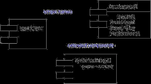
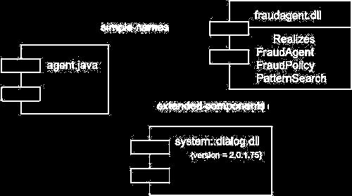
261 component
262 Components and Classes there are some significant differences between components and classes. Classes represent logical abstractions; components represent physical things that live in the world of bits. In short, components may live on nodes, classes may not. Components represent the physical packaging of otherwise logical components and are at a different level of abstraction. Classes may have attributes and operations directly. In general, components only have operations that are reachable only through their interfaces.
263
264 Components and Interfaces An interface is a collection of operations that are used to specify a service of a class or a component. The relationship between component and interface is important. All the most common component-based operating system facilities (such as COM+, CORBA, and Enterprise Java Beans) use interfaces as the glue that binds components together. An interface that a component realizes is called an export interface, meaning an interface that the component provides as a service to other components. A component may provide many export interfaces. The interface that a component uses is called an import interface, meaning an interface that the component conforms to and so builds on. A component may conform to many import interfaces. Also, a component may both import and export interfaces.
265 Components and Interfaces
266 Binary Replaceability The basic intent of every component-based operating system facility is to permit the assembly of systems from binary replaceable parts. This means that you can create a system out of components and then evolve that system by adding new components and replacing old ones, without rebuilding the system. Interfaces are the key to making this happen. When you specify an interface, you can drop into the executable system any component that conforms to or provides that interface. You can extend the system by making the components provide new services through other interfaces, which, in turn, other components can discover and use. These semantics explain the intent behind the definition of components in the UML.
267 Kinds of Components Three kinds of components may be distinguished First, there are deployment components. Second, there are work product components. Third are execution components. Organizing Components You can organize components by grouping them in packages in the same manner in which you organize classes. The UML defines five standard stereotypes that apply to components
268 The UML defines five standard stereotypes that apply to components 1.Executable 2. library 3. table 4. file 5. Document
269 Common Modeling Techniques Modeling Executables and Libraries To model executables and libraries, Identify the partitioning of your physical system. Consider the impact of technical, configuration management, and reuse issues. Model any executables and libraries as components, using the appropriate standard elements. If your implementation introduces new kinds of components, introduce a new appropriate stereotype.
270 Modeling Executables and Libraries contd If it's important for you to manage the seams in your system, model the significant interfaces that some components use and others realize. As necessary to communicate your intent, model the relationships among these executables, libraries, and interfaces. Most often, you'll want to model the dependencies among these parts in order to visualize the impact of change.

271 Modeling Executables and Libraries contd
272 Modeling Tables, Files, and Documents To model tables, files, and documents, Identify the ancillary components that are part of the physical implementation of your system. Model these things as components. If your implementation introduces new kinds of artifacts, introduce a new appropriate stereotype. As necessary to communicate your intent, model the relationships among these ancillary components and the other executables, libraries, and interfaces in your system. Most often, you'll want to model the dependencies among these parts in order to visualize the impact of change.
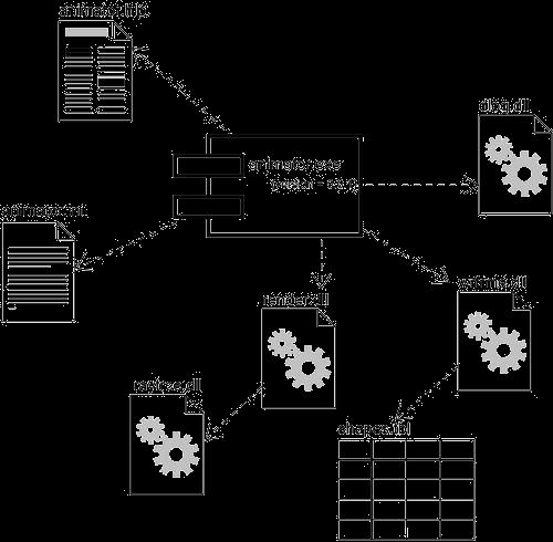
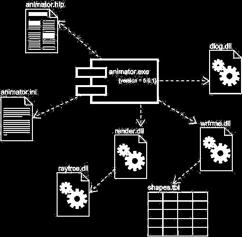
273
274 To model an API, Modeling an API Identify the programmatic seams in your system and model each seam as an interface, collecting the attributes and operations that form this edge. Expose only those properties of the interface that are important to visualize in the given context; otherwise, hide these properties, keeping them in the interface's specification for reference, as necessary. Model the realization of each API only insofar as it is important to show the configuration of a specific implementation.
275 Modeling an API
276 Modeling Source Code To model source code, Depending on the constraints imposed by your development tools, model the files used to store the details of all your logical elements, along with their compilation dependencies. If it's important for you to bolt these models to your configuration management and version control tools, you'll want to include tagged values, such as version, author, and check in/check out information, for each file that's under configuration management. As far as possible, let your development tools manage the relationships among these files, and use the UML only to visualize and document these relationships.

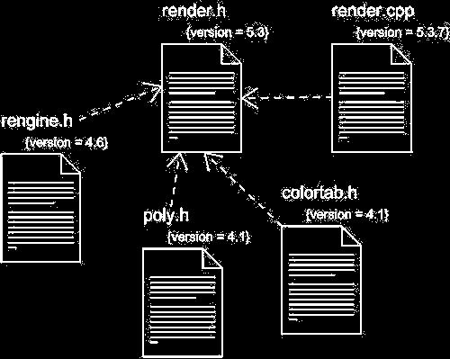
277 Modeling Source Code
278 Deployment A node is a physical element that exists at run time and represents a computational resource, generally having at least some memory and, often, processing capability. Graphically, a node is rendered as a cube. Every node must have a name that distinguishes it from other nodes. A name is a textual string. That name alone is known as a simple name; a path name is the node name prefixed by the name of the package in which that node lives. A node is typically drawn showing only its name, as in. Just as with classes, you may draw nodes adorned with tagged values or with additional compartments to expose their details.
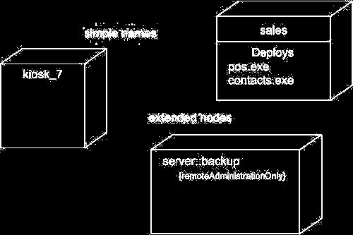
279 Deployment contd
280 Nodes and Components there are some significant differences between nodes and components. Components are things that participate in the execution of a system; nodes are things that execute components. Components represent the physical packaging of otherwise logical elements; nodes represent the physical deployment of components.
281 Nodes and Components
282 Connections The most common kind of relationship you'll use among nodes is an association. In this context, an association represents a physical connection among nodes, such as an Ethernet connection, a serial line, or a shared bus, as Figure.
283 Common Modeling Techniques Modeling Processors and Devices To model processors and devices, Identify the computational elements of your system's deployment view and model each as a node. If these elements represent generic processors and devices, then stereotype them as such. If they are kinds of processors and devices that are part of the vocabulary of your domain, then specify an appropriate stereotype with an icon for each. As with class modeling, consider the attributes and operations that might apply to each node.
284 Modeling Processors and Devices contd.
285 Modeling the Distribution of Components To model the distribution of components, For each significant component in your system, allocate it to a given node. Consider duplicate locations for components. It's not uncommon for the same kind of component (such as specific executables and libraries) to reside on multiple nodes simultaneously. Render this allocation in one of three ways. Don't make the allocation visible, but leave it as part of the backplane of your model that is, in each node's specification. Using dependency relationships, connect each node with the components it deploys. List the components deployed on a node in an additional
286 Modeling the Distribution of Components contd..
287 Component Diagrams A component diagram shows a set of components and their relationships. Graphically, a component diagram is a collection of vertices and arcs. Contents Component diagrams commonly contain Components Interfaces Dependency, generalization, association, and realization relationships Like all other diagrams, component diagrams may contain notes and constraints.
288 Common uses When you model the static implementation view of a system, you'll typically use component diagrams in one of four ways. To model source code 2 model executable releases To model physical databases To model adaptable systems
289 Common Modeling Techniques Modeling Source Code To model a system's source code, Either by forward or reverse engineering, identify the set of source code files of interest and model them as components stereotyped as files. For larger systems, use packages to show groups of source code files. Consider exposing a tagged value indicating such information as the version number of the source code file, its author, and the date it was last changed. Use tools to manage the value of this tag. Model the compilation dependencies among these files using dependencies. Again, use tools to help generate and manage these dependencies.

290 Modeling Source Code contd.
291 Modeling an Executable Release To model an executable release Identify the set of components you'd like to model. Typically, this will involve some or all the components that live on one node, or the distribution of these sets of components across all the nodes in the system. Consider the stereotype of each component in this set. For most systems, you'll find a small number of different kinds of components (such as executables, libraries, tables, files, and documents). You can use the UML's extensibility mechanisms to provide visual cues for these stereotypes.
292 Modeling an Executable Release contd. For each component in this set, consider its relationship to its neighbors. Most often, this will involve interfaces that are exported (realized) by certain components and then imported (used) by others. If you want to expose the seams in your system, model these interfaces explicitly. If you want your model at a higher level of abstraction, elide these relationships by showing only dependencies among the components.
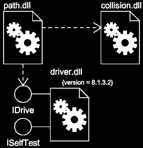
293
294 Modeling a Physical Database to model a physical database, Identify the classes in your model that represent your logical database schema. Select a strategy for mapping these classes to tables. You will also want to consider the physical distribution of your databases. Your mapping strategy will be affected by the location in which you want your data to live on your deployed system. To visualize, specify, construct, and document your mapping, create a component diagram that contains components stereotyped as tables. Where possible, use tools to help you transform your logical design into a physical design.


295 Modeling a Physical Database contd
296 Modeling Adaptable Systems Consider the physical distribution of the components that may migrate from node to node. You can specify the location of a component instance by marking it with a location tagged value, which you can then render in a component diagram (although, technically speaking, a diagram that contains only instances is an object diagram). If you want to model the actions that cause a component to migrate, create a corresponding interaction diagram that contains component instances. You can illustrate a change of location by drawing the same instance more than once, but with different values for its location tagged value.

297 Modeling Adaptable Systems contd
298 Forward and Reverse Engineering To forward engineer a component diagram, For each component, identify the classes or collaborations that the component implements. Choose the target for each component. Your choice is basically between source code (a form that can be manipulated by development tools) or a binary library or executable (a form that can be dropped into a running system). Use tools to forward engineer your models.
299 Forward and Reverse Engineering To reverse engineer a component diagram, Choose the target you want to reverse engineer. Source code can be reverse engineered to components and then classes. Binary libraries can be reverse engineered to uncover their interfaces. Executables can be reverse engineered the least. Using a tool, point to the code you'd like to reverse engineer. Use your tool to generate a new model or to modify an existing one that was previously forward engineered. Using your tool, create a component diagram by querying the model. For example, you might start with one or more components, then expand the diagram by following relationships or neighboring components. Expose or hide the details of the contents of this component diagram as necessary to communicate your intent.

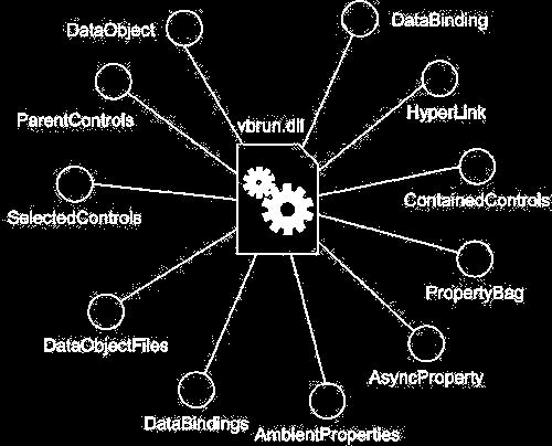
300 Forward and Reverse Engineering
301 Deployment Diagrams A deployment is a diagram that shows the configuration of run time processing nodes and the components that live on them. Graphically, a deployment diagram is a collection of vertices and arcs. Contents Deployment diagrams commonly contain Nodes Dependency and association relationships Like all other diagrams, deployment diagrams may contain notes and constraints
302 Common Uses When you model the static deployment view of a system, you'll typically use deployment diagrams in one of three ways. 1. To model embedded systems 2. To model client/server systems 3. To model fully distributed systems
303 Common Modeling Techniques Modeling an Embedded System To model an embedded system, Identify the devices and nodes that are unique to your system. Provide visual cues, especially for unusual devices, by using the UML's extensibility mechanisms to define system-specific stereotypes with appropriate icons. At the very least, you'll want to distinguish processors (which contain software components) and devices (which, at that level of abstraction, don't directly contain software).
304 Modeling an Embedded System contd. Model the relationships among these processors and devices in a deployment diagram. Similarly, specify the relationship between the components in your system's implementation view and the nodes in your system's deployment view. As necessary, expand on any intelligent devices by modeling their structure with a more detailed deployment diagram.

305 Modeling an Embedded System contd.
306 Modeling a Client/Server System To model a client/server system, Identify the nodes that represent your system's client and server processors. Highlight those devices that are germane to the behavior of your system. For example, you'll want to model special devices, such as credit card readers, badge readers, and display devices other than monitors, because their placement in the system's hardware topology are likely to be architecturally significant. Provide visual cues for these processors and devices via stereotyping. Model the topology of these nodes in a deployment diagram. Similarly, specify the relationship between the components in your system's implementation view and the nodes in your system's deployment view.
307 Modeling a Client/Server System
308 Modeling a Fully Distributed System To model a fully distributed system, Identify the system's devices and processors as for simpler client/server systems. If you need to reason about the performance of the system's network or the impact of changes to the network, be sure to model these communication devices to the level of detail sufficient to make these assessments. Pay close attention to logical groupings of nodes, which you can specify by using packages.
309 Modeling a Fully Distributed System Model these devices and processors using deployment diagrams. Where possible, use tools that discover the topology of your system by walking your system's network. If you need to focus on the dynamics of your system, introduce use case diagrams to specify the kinds of behavior you are interested in, and expand on these use cases with interaction diagrams.

310 Modeling a Fully Distributed System
311 Forward and Reverse Engineering To reverse engineer a deployment diagram, Choose the target that you want to reverse engineer. In some cases, you'll want to sweep across your entire network; in others, you can limit your search. Choose also the fidelity of your reverse engineering. In some cases, it's sufficient to reverse engineer just to the level of all the system's processors; in others, you'll want to reverse engineer the system's networking peripherals, as well. Use a tool that walks across your system, discovering its hardware topology. Record that topology in a deployment model.
312 Forward and Reverse Engineering contd. Along the way, you can use similar tools to discover the components that live on each node, which you can also record in a deployment model. You'll want to use an intelligent search, for even a basic personal computer can contain gigabytes of components, many of which may not be relevant to your system. Using your modeling tools, create a deployment diagram by querying the model. For example, you might start with visualizing the basic client/server topology, then expand on the diagram by populating certain nodes with components of interest that live on them. Expose or hide the details of the contents of this deployment diagram as necessary to communicate your intent.
313 UNIT-V Case Study Library Application

314 Identification of actors and use cases:

315 diagram for library system: Fig:

316

317 Sequence diagram for use case Return Item:

318 Fig: collaboration diagram for use case Return Item

319 Sequence diagram for use cases: Checkout Item
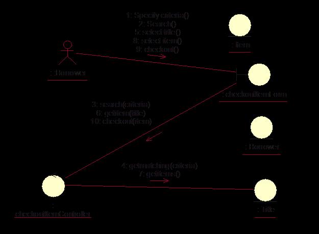
320
321 Sequence diagram for use case login: : UserLocator :EmployeeActor : EmployeeLoginUI : LoginWorkflow : User displayloginform() submitname AndPassword() validatelogin() findbyname() NULL( ) INVALID displayerrormessage()

322 Fig: collaboration diagram for login

323 Activity diagram for library application:

324 STATE MACHINE DIAGRAM FOR THE TITLE CLASS:

325 STATE DIAGRAM FOR LIBRARY SYSTEM

326 Component diagram for library application:
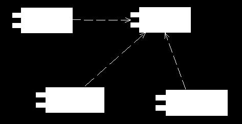
327

328 Deployment diagram for library applications
329
UNIT-II I. BASIC STRUCTURAL MODELING
 UNIT-II I. BASIC STRUCTURAL MODELING Contents: 1. Classes 2. Relationships 3. Common Mechanisms 4. Diagrams 1. Classes: Terms and Concepts: A class is a description of a set of objects that share the same
user.book Page 45 Friday, April 8, :05 AM Part 2 BASIC STRUCTURAL MODELING
 user.book Page 45 Friday, April 8, 2005 10:05 AM Part 2 BASIC STRUCTURAL MODELING user.book Page 46 Friday, April 8, 2005 10:05 AM user.book Page 47 Friday, April 8, 2005 10:05 AM Chapter 4 CLASSES In
Basic Structural Modeling. Copyright Joey Paquet,
 Basic Structural Modeling Copyright Joey Paquet, 2000 1 Part I Classes Copyright Joey Paquet, 2000 2 Classes Description of a set of objects sharing the same attributes, operations and semantics Abstraction
Software Design Methodologies and Testing. (Subject Code: ) (Class: BE Computer Engineering) 2012 Pattern
 (Class: BE Computer Engineering) 2012 Pattern") Software Design Methodologies and Testing (Subject Code: 410449) (Class: BE Computer Engineering) 2012 Pattern Objectives and outcomes Course Objectives To understand and apply different design methods
Software Design Methodologies and Testing (Subject Code: 410449) (Class: BE Computer Engineering) 2012 Pattern Objectives and outcomes Course Objectives To understand and apply different design methods
Unit II. Advanced Structural Modeling
 Unit II Advanced Structural Modeling A relationship is a connection among things. In object-oriented modeling, the four most important relationships are dependencies, generalizations, associations, and
UNIT-IV BASIC BEHAVIORAL MODELING-I
 UNIT-IV BASIC BEHAVIORAL MODELING-I CONTENTS 1. Interactions Terms and Concepts Modeling Techniques 2. Interaction Diagrams Terms and Concepts Modeling Techniques Interactions: Terms and Concepts: An interaction
UNIT V *********************************************************************************************
 Syllabus: 1 UNIT V 5. Package Diagram, Component Diagram, Deployment Diagram (08 Hrs, 16 Marks) Package Diagram: a. Terms and Concepts Names, Owned Elements, Visibility, Importing and Exporting b. Common
Interactions A link message
 Interactions An interaction is a behavior that is composed of a set of messages exchanged among a set of objects within a context to accomplish a purpose. A message specifies the communication between
UNIT II. Syllabus. a. An Overview of the UML: Visualizing, Specifying, Constructing, Documenting
 UNIT II Syllabus Introduction to UML (08 Hrs, 16 Marks) a. An Overview of the UML: Visualizing, Specifying, Constructing, Documenting b. Background, UML Basics c. Introducing UML 2.0 A Conceptual Model
CS/IT Secure Software Construction
 CS/IT 328 - Secure Software Construction Chapter 6 Class-Diagrams Relationships and Associations Book: Fowler Class Diagrams Class diagrams and models can be looked at from three different perspectives:
Allenhouse Institute of Technology (UPTU Code : 505) OOT Notes By Hammad Lari for B.Tech CSE V th Sem
 OOT Notes By Hammad Lari for B.Tech CSE V th Sem") UNIT-1 ECS-503 Object Oriented Techniques Part-1: Object-Oriented Programming Concepts What Is an Object? Objects are key to understanding object-oriented technology. Look around right now and you'll find
UNIT-1 ECS-503 Object Oriented Techniques Part-1: Object-Oriented Programming Concepts What Is an Object? Objects are key to understanding object-oriented technology. Look around right now and you'll find
LABORATORY 1 REVISION
 UTCN Computer Science Department Software Design 2012/2013 LABORATORY 1 REVISION ================================================================== I. UML Revision This section focuses on reviewing the
UNIT-II Introduction to UML
 UNIT-II Introduction to UML - P. P. Mahale UML OVERVIEW OF UML :- We need a Modeling Language! We will use the Unified Modeling Language, UML), Provides a standard for artifacts produced during development
Software Service Engineering
 Software Service Engineering Lecture 4: Unified Modeling Language Doctor Guangyu Gao Some contents and notes selected from Fowler, M. UML Distilled, 3rd edition. Addison-Wesley Unified Modeling Language
SOFTWARE DESIGN COSC 4353 / Dr. Raj Singh
 SOFTWARE DESIGN COSC 4353 / 6353 Dr. Raj Singh UML - History 2 The Unified Modeling Language (UML) is a general purpose modeling language designed to provide a standard way to visualize the design of a
Advanced Software Engineering
 Dev Bhoomi Institute Of Technology LABORATORY MANUAL PRACTICAL INSTRUCTION SHEET EXPERIMENT NO. ISSUE NO. : ISSUE DATE: REV. NO. : REV. DATE : PAGE: 1 LABORATORY Name & Code: Advanced Software Engineering
Modellistica Medica. Maria Grazia Pia, INFN Genova. Scuola di Specializzazione in Fisica Sanitaria Genova Anno Accademico
 Modellistica Medica Maria Grazia Pia INFN Genova Scuola di Specializzazione in Fisica Sanitaria Genova Anno Accademico 2002-2003 Lezione 6 UML Introduction Structural diagrams Basics What is? Please explain
A - 1. CS 494 Object-Oriented Analysis & Design. UML Class Models. Overview. Class Model Perspectives (cont d) Developing Class Models
 Developing Class Models") CS 494 Object-Oriented Analysis & Design UML Class Models Overview How class models are used? Perspectives Classes: attributes and operations Associations Multiplicity Generalization and Inheritance Aggregation
CS 494 Object-Oriented Analysis & Design UML Class Models Overview How class models are used? Perspectives Classes: attributes and operations Associations Multiplicity Generalization and Inheritance Aggregation
Introduction to Software Engineering. 5. Modeling Objects and Classes
 Introduction to Software Engineering 5. Modeling Objects and Classes Roadmap > UML Overview > Classes, attributes and operations > UML Lines and Arrows > Parameterized Classes, Interfaces and Utilities
OMG Modeling Glossary B
 OMG Modeling Glossary B This glossary defines the terms that are used to describe the Unified Modeling Language (UML) and the Meta Object Facility (MOF). In addition to UML and MOF specific terminology,
NOTES ON OBJECT-ORIENTED MODELING AND DESIGN
 NOTES ON OBJECT-ORIENTED MODELING AND DESIGN Stephen W. Clyde Brigham Young University Provo, UT 86402 Abstract: A review of the Object Modeling Technique (OMT) is presented. OMT is an object-oriented
UML Fundamental. OutLine. NetFusion Tech. Co., Ltd. Jack Lee. Use-case diagram Class diagram Sequence diagram
 UML Fundamental NetFusion Tech. Co., Ltd. Jack Lee 2008/4/7 1 Use-case diagram Class diagram Sequence diagram OutLine Communication diagram State machine Activity diagram 2 1 What is UML? Unified Modeling
A Conceptual Model of the UML
 CONTENT A Conceptual Model of the UML Building Blocks of the UML 1. Things [1.1] Structural Things (1.1.1) Class (1.1.2) Interface (1.1.3) Collaboration: (1.1.4) Use case (1.1.5) Components: (1.1.6) Node:
INTRODUCING THE UML. Chapter 2
 chap02.fm Page 13 Friday, October 27, 2000 10:26 AM Chapter 2 INTRODUCING THE UML In this chapter Overview of the UML Three steps to understanding the UML Software architecture The software development
UNIT-I Introduction of Object Oriented Modeling
 UNIT-I Introduction of Object Oriented Modeling - Prasad Mahale Object Oriented Modeling and Reference Books: Design 1. Grady Booch, James Rumbaugh, Ivar Jacobson Unified Modeling Language User Guide,
Chapter 2: The Object-Oriented Design Process
 Chapter 2: The Object-Oriented Design Process In this chapter, we will learn the development of software based on object-oriented design methodology. Chapter Topics From Problem to Code The Object and
Introduction to UML Dr. Rajivkumar S. Mente
 Introduction to UML Dr. Rajivkumar S. Mente Assistant Professor, Department of Computer Science, Solapur University, Solapur rajivmente@rediffmail.com Introduction to UML UML is a language used for 1.
Introduction to UML. Danang Wahyu utomo
 Introduction to UML Danang Wahyu utomo danang.wu@dsn.dinus.ac.id 085 740 955 623 Evolution of OO Development Methods History of OOAD leading to UML Why Model? Analyse the problem domain - Simplify reality
MAHARASHTRA STATE BOARD OF TECHNICAL EDUCATION (Autonomous) (ISO/IEC Certified)
 (ISO/IEC Certified)") Subject Code: 17630 Model Answer Page No: 1 /32 Important Instructions to examiners: 1) The answers should be examined by keywords and not as word-to-word as given in the model answer scheme. 2) The model
Subject Code: 17630 Model Answer Page No: 1 /32 Important Instructions to examiners: 1) The answers should be examined by keywords and not as word-to-word as given in the model answer scheme. 2) The model
History of object-oriented approaches
 Prof. Dr. Nizamettin AYDIN naydin@yildiz.edu.tr http://www.yildiz.edu.tr/~naydin Object-Oriented Oriented Systems Analysis and Design with the UML Objectives: Understand the basic characteristics of object-oriented
Object-Oriented Software Engineering Practical Software Development using UML and Java
 Object-Oriented Software Engineering Practical Software Development using UML and Java Chapter 5: Modelling with Classes Lecture 5 5.1 What is UML? The Unified Modelling Language is a standard graphical
Chapter No. 2 Class modeling CO:-Sketch Class,object models using fundamental relationships Contents 2.1 Object and Class Concepts (12M) Objects,
 Objects,") Chapter No. 2 Class modeling CO:-Sketch Class,object models using fundamental relationships Contents 2.1 Object and Class Concepts (12M) Objects, Classes, Class Diagrams Values and Attributes Operations
Chapter No. 2 Class modeling CO:-Sketch Class,object models using fundamental relationships Contents 2.1 Object and Class Concepts (12M) Objects, Classes, Class Diagrams Values and Attributes Operations
Ingegneria del Software Corso di Laurea in Informatica per il Management. Introduction to UML
 Ingegneria del Software Corso di Laurea in Informatica per il Management Introduction to UML Davide Rossi Dipartimento di Informatica Università di Bologna Modeling A model is an (abstract) representation
UNIT 5 - UML STATE DIAGRAMS AND MODELING
 UNIT 5 - UML STATE DIAGRAMS AND MODELING UML state diagrams and modeling - Operation contracts- Mapping design to code UML deployment and component diagrams UML state diagrams: State diagrams are used
Lesson 11. W.C.Udwela Department of Mathematics & Computer Science
 Lesson 11 INTRODUCING UML W.C.Udwela Department of Mathematics & Computer Science Why we model? Central part of all the activities We build model to Communicate Visualize and control Better understand
administrivia today UML start design patterns Tuesday, September 28, 2010
 administrivia Assignment 2? promise to get past assignment 1 back soon exam on monday review slides are posted your responsibility to review covers through last week today UML start design patterns 1 Unified
MAHARASHTRA STATE BOARD OF TECHNICAL EDUCATION (Autonomous) (ISO/IEC Certified)
 (ISO/IEC Certified)") Important Instructions to examiners: 1) The answers should be examined by key words and not as word-to-word as given in the model answer scheme. 2) The model answer and the answer written by candidate
Important Instructions to examiners: 1) The answers should be examined by key words and not as word-to-word as given in the model answer scheme. 2) The model answer and the answer written by candidate
CHAPTER 1. Topic: UML Overview. CHAPTER 1: Topic 1. Topic: UML Overview
 CHAPTER 1 Topic: UML Overview After studying this Chapter, students should be able to: Describe the goals of UML. Analyze the History of UML. Evaluate the use of UML in an area of interest. CHAPTER 1:
Object-Oriented Design
 Object-Oriented Design Lecture 14: Design Workflow Department of Computer Engineering Sharif University of Technology 1 UP iterations and workflow Workflows Requirements Analysis Phases Inception Elaboration
Introduction to Software Engineering. 5. Modeling Objects and Classes
 Introduction to Software Engineering 5. Modeling Objects and Classes Roadmap > UML Overview > Classes, attributes and operations > UML Lines and Arrows > Parameterized Classes, Interfaces and Utilities
OO Analysis and Design with UML 2 and UP
 OO Analysis and Design with UML 2 and UP Dr. Jim Arlow, Zuhlke Engineering Limited Clear View Training 2008 v2.5 1 UML principles Clear View Training 2008 v2.5 2 1.2 What is UML? Unified Modelling Language
UML (Unified Modeling Language)
") UML (Unified Modeling Language) UML Outline Software Institute of Nanjing University 2009 Instructor 刘嘉 (Liu Jia) Email : liujia@software.nju.edu.cn ext : 509 Office : 705 2 References [1] The Unified
UML (Unified Modeling Language) UML Outline Software Institute of Nanjing University 2009 Instructor 刘嘉 (Liu Jia) Email : liujia@software.nju.edu.cn ext : 509 Office : 705 2 References [1] The Unified
Chapter 5: Structural Modeling
 Chapter 5: Structural Modeling Objectives Understand the rules and style guidelines for creating CRC cards, class diagrams, and object diagrams. Understand the processes used to create CRC cards, class
UML- a Brief Look UML and the Process
 UML- a Brief Look UML grew out of great variety of ways Design and develop object-oriented models and designs By mid 1990s Number of credible approaches reduced to three Work further developed and refined
UNIT I. 3. Write a short notes on process view of 4+1 architecture. 4. Why is object-oriented approach superior to procedural approach?
 Department: Information Technology Questions Bank Class: B.E. (I.T) Prof. Bhujbal Dnyaneshwar K. Subject: Object Oriented Modeling & Design dnyanesh.bhujbal11@gmail.com ------------------------------------------------------------------------------------------------------------
Software Engineering from a
 Software Engineering from a modeling perspective Robert B. France Dept. of Computer Science Colorado State University USA france@cs.colostate.edu Softwaredevelopment problems Little or no prior planning
Topic 3 Unified Modeling Language UML. Objective: Student will use UML to represent relationshiops between objects, its structure and dynamics.
 Topic 3 Unified Modeling Language UML Objective: Student will use UML to represent relationshiops between objects, its structure and dynamics. Contents: 1. Structure diagrams 2. Behavior diagrams What
UML & OO FUNDAMENTALS CSCI 4448/5448: OBJECT-ORIENTED ANALYSIS & DESIGN LECTURE 3 08/30/2011
 UML & OO FUNDAMENTALS CSCI 4448/5448: OBJECT-ORIENTED ANALYSIS & DESIGN LECTURE 3 08/30/2011 1 Goals of the Lecture Review the material in Chapter 2 of the Textbook Cover key parts of the UML notation
Object-Oriented and Classical Software Engineering
 Slide 16.1 Object-Oriented and Classical Software Engineering Seventh Edition, WCB/McGraw-Hill, 2007 Stephen R. Schach srs@vuse.vanderbilt.edu CHAPTER 16 Slide 16.2 MORE ON UML 1 Chapter Overview Slide
SE 1: Software Requirements Specification and Analysis
 SE 1: Software Requirements Specification and Analysis Lecture 9: UML Class (Concept), Object, Communication Diagrams Nancy Day, Davor Svetinović http://www.student.cs.uwaterloo.ca/ cs445/winter2006 uw.cs.cs445
CASE TOOLS LAB VIVA QUESTION
 1. Define Object Oriented Analysis? VIVA QUESTION Object Oriented Analysis (OOA) is a method of analysis that examines requirements from the perspective of the classes and objects found in the vocabulary
Software Engineering Lab Manual
 Kingdom of Saudi Arabia Ministry Education Prince Sattam Bin Abdulaziz University College of Computer Engineering and Sciences Department of Computer Science Software Engineering Lab Manual 1 Background:-
UML REFERENCE SHEETS. 2013, 2014 Michael Marking; all rights reserved, including moral rights. Web site:
 UML Reference Sheets 2013, 2014 Michael Marking; all rights reserved, including moral rights. Web site: http://www.tatanka.com/ Revision Information This document was last revised 2014.03.02. The current
Object-Oriented Software Engineering Practical Software Development using UML and Java. Chapter 5: Modelling with Classes
 Object-Oriented Software Engineering Practical Software Development using UML and Java Chapter 5: Modelling with Classes 5.1 What is UML? The Unified Modelling Language is a standard graphical language
Object-Oriented Systems Analysis and Design Using UML
 10 Object-Oriented Systems Analysis and Design Using UML Systems Analysis and Design, 8e Kendall & Kendall Copyright 2011 Pearson Education, Inc. Publishing as Prentice Hall Learning Objectives Understand
CS112 Lecture: Defining Classes. 1. To describe the process of defining an instantiable class
 CS112 Lecture: Defining Classes Last revised 2/3/06 Objectives: 1. To describe the process of defining an instantiable class Materials: 1. BlueJ SavingsAccount example project 2. Handout of code for SavingsAccount
Chapter 10. Object-Oriented Analysis and Modeling Using the UML. McGraw-Hill/Irwin
 Chapter 10 Object-Oriented Analysis and Modeling Using the UML McGraw-Hill/Irwin Copyright 2007 by The McGraw-Hill Companies, Inc. All rights reserved. Objectives 10-2 Define object modeling and explain
Unified Modeling Language
 Unified Modeling Language Modeling Applications using Language Mappings Programmer s Reference Manual How to use this Reference Card: The consists of a set of fundamental modeling elements which appear
COSC 3351 Software Design. An Introduction to UML (I)
") COSC 3351 Software Design An Introduction to UML (I) This lecture contains material from: http://wps.prenhall.com/esm_pfleeger_softengtp_2 http://sunset.usc.edu/classes/cs577a_2000/lectures/05/ec-05.ppt
COSC 3351 Software Design An Introduction to UML (I) This lecture contains material from: http://wps.prenhall.com/esm_pfleeger_softengtp_2 http://sunset.usc.edu/classes/cs577a_2000/lectures/05/ec-05.ppt
Lecture Notes UML UNIT-II. Subject: OOAD Semester: 8TH Course No: CSE-802
 UNIT-II Lecture Notes On UML IMPORTANCE OF MODELING, BRIEF OVERVIEW OF OBJECT MODELING TECHNOLOGY (OMT) BY RAMBAUGH, BOOCH METHODOLOGY, USE CASE DRIVE APPROACH (OOSE) BY JACKOBSON. KHALID AMIN AKHOON 1
The UML Extension Mechanisms
 Jasmine Farhad Dept of Computer Science University College London 13-Dec-02 The UML Extension Mechanisms Introduction There is an important need for organisations to evolve in today s market. This has
Lab Manual. Object Oriented Analysis And Design. TE(Computer) VI semester
 VI semester") Lab Manual Object Oriented Analysis And Design TE(Computer) VI semester Index Sr. No. Title of Programming Assignment Page No. 1 2 3 4 5 6 7 8 9 10 Study of Use Case Diagram Study of Activity Diagram Study
Lab Manual Object Oriented Analysis And Design TE(Computer) VI semester Index Sr. No. Title of Programming Assignment Page No. 1 2 3 4 5 6 7 8 9 10 Study of Use Case Diagram Study of Activity Diagram Study
Vidyalankar. T.Y. Diploma : Sem. VI [IF/CM] Object Oriented Modeling and Design Prelim Question Paper Solution
![Vidyalankar. T.Y. Diploma : Sem. VI [IF/CM] Object Oriented Modeling and Design Prelim Question Paper Solution](/thumbs/86/94007497.jpg "Vidyalankar. T.Y. Diploma : Sem. VI [IF/CM] Object Oriented Modeling and Design Prelim Question Paper Solution") T.Y. Diploma : Sem. VI [IF/CM] Object Oriented Modeling and Design Prelim Question Paper Solution Q.1(a) Attempt any THREE of the following [12] Q.1(a) (i) What is modeling? Also state its four features.
T.Y. Diploma : Sem. VI [IF/CM] Object Oriented Modeling and Design Prelim Question Paper Solution Q.1(a) Attempt any THREE of the following [12] Q.1(a) (i) What is modeling? Also state its four features.
Introduction to UML CHAPTER 1. Visualizing. Specifying LEARNING OBJECTIVES
 CHAPTER 1 Introduction to UML UML is an acronym for Unified Modeling Language. As its name indicates, it is a graphical language, used to create visual models of software intensive systems. The UML is
2 UML for OOAD. 2.1 What is UML? 2.2 Classes in UML 2.3 Relations in UML 2.4 Static and Dynamic Design with UML. UML for OOAD Stefan Kluth 1
 2 UML for OOAD 2.1 What is UML? 2.2 Classes in UML 2.3 Relations in UML 2.4 Static and Dynamic Design with UML UML for OOAD Stefan Kluth 1 2.1 UML Background "The Unified Modelling Language (UML) is a
Agenda. Why Model. Why Model? History of OO Modeling Methodologies Object Modeling Technique (OMT) Unified Modeling Language (UML)
 Unified Modeling Language (UML)") Agenda Why Model? History of OO Modeling Methodologies Object Modeling Technique (OMT) Why Model def n: simplification of reality Create a Successful Product Aids in Better Understanding of System Attack
Agenda Why Model? History of OO Modeling Methodologies Object Modeling Technique (OMT) Why Model def n: simplification of reality Create a Successful Product Aids in Better Understanding of System Attack
Chapter 1: Principles of Programming and Software Engineering
 Chapter 1: Principles of Programming and Software Engineering Data Abstraction & Problem Solving with C++ Fifth Edition by Frank M. Carrano Software Engineering and Object-Oriented Design Coding without
OBJECT ORIENTED ANALYSIS AND DESIGN
 LECTURE NOTES ON OBJECT ORIENTED ANALYSIS AND DESIGN III B. Tech II semester (JNTUH-R15) Ms. K Mayuri Assistant Professor INSTITUTE OF AERONAUTICAL ENGINEERING (Autonomous) Dundigal, Hyderabad - 500 043
UML 2.0 State Machines
 UML 2.0 State Machines Frederic.Mallet@unice.fr Université Nice Sophia Antipolis M1 Formalisms for the functional and temporal analysis With R. de Simone Objectives UML, OMG and MDA Main diagrams in UML
Enterprise Architect. User Guide Series. UML Models. Author: Sparx Systems. Date: 30/06/2017. Version: 1.0 CREATED WITH
 Enterprise Architect User Guide Series UML Models Author: Sparx Systems Date: 30/06/2017 Version: 1.0 CREATED WITH Table of Contents UML Models UML Diagrams UML Structural Models Class Diagram Composite
UNIT-4 Behavioral Diagrams
 UNIT-4 Behavioral Diagrams P. P. Mahale Behavioral Diagrams Use Case Diagram high-level behaviors of the system, user goals, external entities: actors Sequence Diagram focus on time ordering of messages
Software Architecture. Lecture 5
 Software Architecture Lecture 5 Roadmap of the course What is software architecture? Designing Software Architecture Requirements: quality attributes or qualities How to achieve requirements : tactics
Meltem Özturan
 Meltem Özturan www.mis.boun.edu.tr/ozturan/samd 1 2 Modeling System Requirements Object Oriented Approach to Requirements OOA considers an IS as a set of objects that work together to carry out the function.
Introducing the UML Eng. Mohammed T. Abo Alroos
 Introducing the UML Eng. Mohammed T. Abo Alroos Islamic University of Gaza Introduction to the UML: The UML stands for Unified Modeling Language. It was released in 1997 as a method to diagram software
Objectives. Explain the purpose and objectives of objectoriented. Develop design class diagrams
 Objectives Explain the purpose and objectives of objectoriented design Develop design class diagrams Develop interaction diagrams based on the principles of object responsibility and use case controllers
The Unified Modelling Language. Example Diagrams. Notation vs. Methodology. UML and Meta Modelling
 UML and Meta ling Topics: UML as an example visual notation The UML meta model and the concept of meta modelling Driven Architecture and model engineering The AndroMDA open source project Applying cognitive
Class diagrams. Modeling with UML Chapter 2, part 2. Class Diagrams: details. Class diagram for a simple watch
 Class diagrams Modeling with UML Chapter 2, part 2 CS 4354 Summer II 2015 Jill Seaman Used to describe the internal structure of the system. Also used to describe the application domain. They describe
Software Architectures. Lecture 6 (part 1)
") Software Architectures Lecture 6 (part 1) 2 Roadmap of the course What is software architecture? Designing Software Architecture Requirements: quality attributes or qualities How to achieve requirements
Software Architectures Lecture 6 (part 1) 2 Roadmap of the course What is software architecture? Designing Software Architecture Requirements: quality attributes or qualities How to achieve requirements
Chapter 2: Entity-Relationship Model
 Chapter 2: Entity-Relationship Model! Entity Sets! Relationship Sets! Design Issues! Mapping Constraints! Keys! E-R Diagram! Extended E-R Features! Design of an E-R Database Schema! Reduction of an E-R
Object Oriented Modeling
 Overview UML Unified Modeling Language What is Modeling? What is UML? A brief history of UML Understanding the basics of UML UML diagrams UML Modeling tools 2 Modeling Object Oriented Modeling Describing
UML Primer. -Elango Sundaram
 UML Primer -Elango Sundaram About UML UML Can be thought of as a blue print for Software Graphical notation for expressing underlying OOA&D ideas Can be used to design any type of application, hardware,
UML Unified Modeling Language
 UML Unified Modeling Language a standard language to analyze, design and document software intensive solutions Modeling with UML Building blocks When you model something, you create a simplification of
Credit where Credit is Due. Lecture 4: Fundamentals of Object Technology. Goals for this Lecture. Real-World Objects
 Lecture 4: Fundamentals of Object Technology Kenneth M. Anderson Object-Oriented Analysis and Design CSCI 6448 - Spring Semester, 2003 Credit where Credit is Due Some material presented in this lecture
12 Tutorial on UML. TIMe TIMe Electronic Textbook
 TIMe TIMe Electronic Textbook 12 Tutorial on UML Introduction......................................................2.................................................3 Diagrams in UML..................................................3
Dr.S.S.Riaz Ahamed Principal, Sathak Institute of Technology, Ramanathapuram,India.
 REVIEW AND ANALYSIS OF THE ISSUES OF UNIFIED MODELING LANGUAGE FOR VISUALIZING, SPECIFYING, CONSTRUCTING AND DOCUMENTING THE ARTIFACTS OF A SOFTWARE-INTENSIVE SYSTEM Dr.S.S.Riaz Ahamed Principal, Sathak
Model Driven Development Unified Modeling Language (UML)
") Model Driven Development Unified Modeling Language (UML) An Overview UML UML is a modeling notation standardized by OMG (proposal 1997, ver.1.1 in 1998, ver. 2.0 in 2004) now in 2.4.1 mature based on notations
Model Driven Development Unified Modeling Language (UML) An Overview UML UML is a modeling notation standardized by OMG (proposal 1997, ver.1.1 in 1998, ver. 2.0 in 2004) now in 2.4.1 mature based on notations
UML & OO Fundamentals. CSCI 4448/5448: Object-Oriented Analysis & Design Lecture 3 09/04/2012
 UML & OO Fundamentals CSCI 4448/5448: Object-Oriented Analysis & Design Lecture 3 09/04/2012 1 Goals of the Lecture Review the material in Chapter 2 of the Textbook Cover key parts of the UML notation
Course "Softwaretechnik" Book Chapter 2 Modeling with UML
 Course "Softwaretechnik" Book Chapter 2 Modeling with UML Lutz Prechelt, Bernd Bruegge, Allen H. Dutoit Freie Universität Berlin, Institut für Informatik http://www.inf.fu-berlin.de/inst/ag-se/ Modeling,
Use Case Model. Static Structure. Diagram. Collaboration. Collaboration. Diagram. Collaboration. Diagram. Diagram. Activity. Diagram.
 !"# $%&' !" #" $%%&&& ! Static Structure Diagram Collaboration Collaboration Diagram Collaboration Diagram Diagram Activity Diagram CRC Card CRC Card UML defines a standard notation for object-oriented
Experiment no 4 Study of Class Diagram in Rational Rose
 Experiment no 4 Study of Class Diagram in Rational Rose Objective-: To studyclass Diagram in Rational Rose. References-: www.developer.com The Unified Modeling Language User Guide by Grady Booch Mastering
Component Design. Systems Engineering BSc Course. Budapest University of Technology and Economics Department of Measurement and Information Systems
 Component Design Systems Engineering BSc Course Budapest University of Technology and Economics Department of Measurement and Information Systems Traceability Platform-based systems design Verification
CHAPTER 5 CO:-Sketch component diagram using basic notations 5.1 Component Diagram (4M) Sample Component Diagram 5.2 Deployment Diagram (8M)
 Sample Component Diagram 5.2 Deployment Diagram (8M)") CHAPTER 5 CO:-Sketch component diagram using basic notations 5.1 Component Diagram (4M) Sample Component Diagram 5.2 Deployment Diagram (8M) Sample Deployment diagram Component diagrams are different in
CHAPTER 5 CO:-Sketch component diagram using basic notations 5.1 Component Diagram (4M) Sample Component Diagram 5.2 Deployment Diagram (8M) Sample Deployment diagram Component diagrams are different in
Methods for requirements engineering
 Methods for requirements engineering Objectives To explain the role of methods and techniques in requirements engineering To introduce data-flow modelling To introduce semantic data modelling To introduce
Index. Add Diagram > Sequence Diagram command,
 Quatrani.book Page 183 Monday, May 8, 2006 11:56 AM Index A abstraction, 3 actions completing before processing, 54 55 data flowing through, 53 passing control between, 51 performing, 155 157 as round-cornered
Analysis and Design with UML
 Analysis and Design with UML Page 1 Agenda Benefits of Visual Modeling History of the UML Visual Modeling with UML The Rational Iterative Development Process Page 2 What is Visual Modeling? Item Order
What are the characteristics of Object Oriented programming language?
 What are the various elements of OOP? Following are the various elements of OOP:- Class:- A class is a collection of data and the various operations that can be performed on that data. Object- This is
Unified Modeling Language (UML)
") Appendix H Unified Modeling Language (UML) Preview The Unified Modeling Language (UML) is an object-oriented modeling language sponsored by the Object Management Group (OMG) and published as a standard
Appendix H Unified Modeling Language (UML) Preview The Unified Modeling Language (UML) is an object-oriented modeling language sponsored by the Object Management Group (OMG) and published as a standard
For 100% Result Oriented IGNOU Coaching and Project Training Call CPD TM : ,
 Course Code : MCS-032 Course Title : Object Oriented Analysis and Design Assignment Number : MCA (3)/032/Assign/2014-15 Assignment Marks : 100 Weightage : 25% Last Dates for Submission : 15th October,
Lecture 34 SDLC Phases and UML Diagrams
 That Object-Oriented Analysis and Design Prof. Partha Pratim Das Department of Computer Science and Engineering Indian Institute of Technology-Kharagpur Lecture 34 SDLC Phases and UML Diagrams Welcome
Design Pattern: Composite
 Design Pattern: Composite Intent Compose objects into tree structures to represent part-whole hierarchies. Composite lets clients treat individual objects and compositions of objects uniformly. Motivation