Validator Update Instructions for Rowe BC1200 $1 - $20
|
|
|
- Annis Morrison
- 5 years ago
- Views:
Transcription
1 Validator Update Instructions for Rowe BC1200 $1 - $20 Kit Overview The purpose of the kit is to replace the Rowe BA50 transport and stacker with a 120 volt Mars validator with a compact mask. The kit and these instructions pertain to a Rowe BC1200, this is a front-loading changer with two hoppers. There are 2 variations of the kit, one will process $1-$5 and the second $1-$20. This kit is designed for dollar bill changers that are not used to make change for a coin. If you are accepting coins please, contact us for a coin interface kit. This stock kit will work in changers with board numbers and The kit will work with all 3 variations of the Rowe BILL CHANGER CONTROL COMPUTER boards; , , and The E prom in board versions and will be changed to 2.7. If you are installing the kit with board number two additional parts are needed. This is the early style obsolete board. Please call us prior to beginning the conversion so they can be sent to you. The parts kit includes a E prom and a transport by-pass harness. Order part number KITCVR Eprom costing $ We can be reached at Capital Vending The installation information is intended for experienced personnel familiar with the operation of these components. All of the installation procedures must be reviewed and understood prior to installing the kit. The installation instructions are based upon a dollar bill changer that has not been modified from the original factory configuration. If the machine has been altered in any way, restore the machine to the original factory configuration prior to beginning the conversion. The installer must know the proper procedures to replace an E prom. Kit Components The kit contains the following parts: Module in black plastic box; labeled BC1200/1400/3500 Metal validator slide plate with wide opening E prom with label BC3500 V2.7 One package of Velcro Additional Required Items Not Included With Kit Working Mars validator Model AE2411/AE2451, VN2511, or AE2611 The four hex nuts used to mount the Mars validator to the validator slide plate are included in the Mars validator shipping box. Dollar bills to test the validator and verify operation of the kit Electrical tape Tools Required 11/32, ¼, and 3/8 long handle nut drivers Pliers Small screwdriver or IC removal tool Optional Tools Required for low coins screw installation Drill 5/16 drill bit Page 1
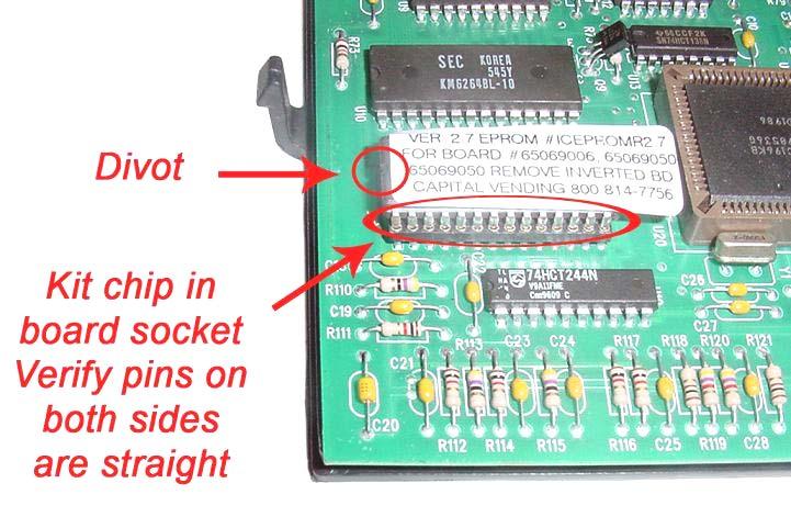
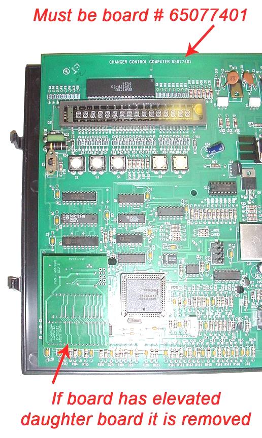
2 Installation Instructions 1. Unplug the power cord from the wall and open the door of the changer. 2. Remove the BA50 bill transport by unplugging the harness at the 15-position harness connector. A 12-inch harness will still be connected to the side of the BA50 transport. 3. Remove the bill box(es) from the stacker assembly. 4. Remove the stacker assembly by unscrewing the two ¼ screws at the top of the assembly. It may be necessary to hold the nuts under the assembly with a pair of pliers. [For changers with a dual stacker: remove the two ¼ screws that secure the stacker assembly base to the bill box bracket. The bill box bracket can remain in the changer] Disconnect the harness from the upper rear right hand side. Slide the stacker assembly forward out of the changer. Replace the upper two screws and nuts. The original stacker harness will not be connected to any component. 5. Set the dip switches on the 120v Mars validator per the label on the kit Module. 6. Unplug the 9-position harness at the Coin Acceptor Assembly. If the changer was not originally equipped with a Coin Acceptor Assembly on the front door, it will be necessary to look behind the hopper assembly for the harness. Figure 4 shows a changer with a factory installed Coin Acceptor Assembly. 7. Insert the 9-position harness from the new Module into the open connector. This kit is not designed for use in a changer that accepts coins. If there is a coin acceptor on the front door the 9-position connector will remain open. If you need to accept coins, please contact us for a coin interface kit. 8. Remove the right hopper from the changer for easy access to the power junction box. 9. Unplug the 3-position power harness from the power junction box located on the upper area of the right side of the cabinet. Plug the 3 position male connector from the kit into the now open connector. Plug the machine harness into the 3 position female connector of the wiring harness from the Module. 10. Mount the kit Module to the right hand wall of the changer using Velcro. See figure Mount the validator onto the metal validator slide plate; the four keps nuts are supplied with the validator. A twelve-inch factory harness may be connected to the validator when it is removed from the box. Unplug this harness, as it is not used with the kit. 12. Set the dip switches on the validator per the label on the Module. 13. Slide the validator plate assembly down the tracks that originally secured the BA50 transport. Attach the harness from the Module with the long black connector to the validator. Note the position of the two keyed pins when attaching the connector. 14. If the machine was not factory fitted with a Coin Acceptor Assembly this step can be skipped. Remove either of the 2 wires from the coin return switch; red or black. Wrap the terminal in electrical tape. 15. The E prom in the control board needs to be changed. It is assumed you are working with board model or Remove the BILL CHANGER CONTROL COMPUTER. 16. Remove the cover from the BILL CHANGER CONTROL COMPUTER. 17. Remove the existing Eprom form the socket. Install the E prom supplied in the parts kit. Be sure to observe the orientation of the notch on the chip. 18. Replace the cover and reinstall the BILL CHANGER CONTROL COMPUTER in the changer. 19. At this point the BILL CHANGER CONTROL COMPUTER is reprogrammed. Plug the cord back into the wall outlet. After a 10 second warm up period the walking blue dash will appear on the BILL CHANGER CONTROL COMPUTER and begin scrolling back and forth. The 3 most popularly used programs are described below. The programming assumes 4 quarters will be dispensed for each dollar value inserted. If you are dispensing dollar coins divide the number of coins to be dispensed by 4. The below instructions can be used as a basis for substituting your own values if needed. The values you are programming may seem odd, however the validator now controls the denominations accepted. The MC mode is recommended if you are dispensing the same value coin in both hoppers. The operation Page 2
3 of the MC Mode is described on page 2-12 in the Rowe BC-1200/1400 Bill & Coin Changer Field Service Manual and Parts Catalog; fifth edition. MC MODE - 4 COINS PER DOLLAR VALUE A. Slide the BILL CHANGER CONTROL COMPUTER forward so it is easy to view the blue display and access the programming buttons. B. Slide the mode switch upwards to the programming mode, the display will read TEMP COUNTERS. C. Depending upon the vintage of the BILL CHANGER CONTROL COMPUTER, the FUNCTION button may be labeled as FUNCTION or FUNCTION-ERROR RESET. These instructions refer to the button as FUNCTION. D. Press the FUNCTION button, the display will read PERM COUNTERS. E. Press the FUNCTION button, the display will read PROGRAMMING. If a security code was entered earlier enter the code now. F. Press the FUNCTION button, the display will read MC PAYOUT. It must be set to ON. Use either of the COUNT SWITCHES BUTTONS to set this option to ON. G. Press the FUNCTION button, the display will read HOP VAL; the value of coins for the left hopper will be flashing. Press the VALUE button until the display reads T1. H. Press the HOPPER button; the display will advance to the right hopper. Press the VALUE button until the display reads T1. I. Press the FUNCTION button, the display will read ACCEPT 1; this is set to NO. The NO and YES options are toggled using the COUNT SWITCHES. J. Press the VALUE button, the display will read ACCEPT 2; this is set to NO. K. Press the VALUE button, the display will read ACCEPT 5; this is set to YES. L. Press the VALUE button, the display will read ACCEPT 10; this is set to NO. M. Press the VALUE button, the display will read ACCEPT 20; this is set to NO. N. Press the VALUE button, the display will read ACCEPT 25; this setting must be set to YES. O. Press the VALUE button, the display will read ACCEPT 25A; this setting is set to NO. P. Press the VALUE button, the display will read ACCEPT 50; this is set to YES. Q. Press the FUNCTION button, the display will show 25 PAY MC MC. Use the COUNT SWITCH BUTTONS to set the value to 4. Use the COUNT SWITCHES to change the value. This value determines the number of coins to be dispensed for a $1 bill; twice the amount of coins for a $2 bill. R. Press the VALUE button, the display will show 50 PAY MC MC. Use the COUNT SWITCHES BUTTONS to set the value to 20. Use the COUNT SWITCHES to change the value. This value determines the number of coins to be dispensed for a $5 bill. S. At this point all of the programming changes needed for the kit have been made, slide the function button down to the NORMAL OPERATING MODE. The display will indicate Storing New Data. T. The walking blue dash will begin scrolling. The 2 green arrows on the validator will begin blinking. U. Skip to #16. NON MC MODE - 2 QUARTERS FROM EACH HOPPER FOR A $1 BILL & 10 QUARTERS FROM EACH HOPPER FOR A $5 BILL A. Slide the BILL CHANGER CONTROL COMPUTER forward so it is easy to view the blue display and access the programming buttons. B. Slide the mode switch upwards to the programming mode, the display will read TEMP COUNTERS. C. Depending upon the vintage of the BILL CHANGER CONTROL COMPUTER, the FUNCTION button may be labeled as FUNCTION or FUNCTION-ERROR RESET. These instructions refer to the button as FUNCTION. Page 3
4 D. Press the FUNCTION button, the display will read PERM COUNTERS. E. Press the FUNCTION button, the display will read PROGRAMMING. If a security code was entered earlier enter the code now. F. Press the FUNCTION button, the display will read MC PAYOUT. It must be set to OFF. Use either of the COUNT SWITCHES BUTTONS to set this option to OFF. G. Press the FUNCTION button, the display will read HOP VAL; the value of coins for the left hopper will be flashing. Press the VALUE button until the display reads T1. H. Press the HOPPER button; the display will advance to the right hopper. Press the VALUE button until the display reads T1. I. Press the FUNCTION button, the display will read ACCEPT 1; this is set to NO. The NO and YES options are toggled using the COUNT SWITCHES. J. Press the VALUE button, the display will read ACCEPT 2; this is set to NO. K. Press the VALUE button, the display will read ACCEPT 5; this is set to YES. L. Press the VALUE button, the display will read ACCEPT 10; this is set to NO. M. Press the VALUE button, the display will read ACCEPT 20; this is set to NO. N. Press the VALUE button, the display will read ACCEPT 25; this setting must be set to YES. O. Press the VALUE button, the display will read ACCEPT 25A; this setting is set to NO. P. Press the VALUE button, the display will read ACCEPT 50; this is set to YES. Q. Press the FUNCTION button, the display will show 25 PAY ---. Use the COUNT SWITCH BUTTONS to change the value for the left hopper to 2. Press the HOPPER button to advance to the right hopper value. Use the COUNT SWITCHES to set the value at 2. This value determines the number of coins to be dispensed for a $1 bill; twice the amount of coins for a $2 bill. R. Press the VALUE button, the display will show 50 PAY ---. Use the COUNT SWITCHES BUTTONS to change the value for the left hopper to 10. Press the HOPPER button to advance to the right hopper value. Use the COUNT SWITCHES to change set the value to 10. This value determines the number of coins to be dispensed for a $5 bill. S. At this point all of the programming changes needed for the kit have been made, slide the function button down to the NORMAL OPERATING MODE. The display will indicate Storing New Data. T. The walking blue dash will begin scrolling. The 2 green arrows on the validator will begin blinking. U. Skip to #16. NON MC MODE - 3 QUARTERS AND 5 NICKELS FOR A $1 BILL & 19 QUARTERS AND 5 NICKELS FOR A $5 BILL A. Slide the BILL CHANGER CONTROL COMPUTER forward so it is easy to view the blue display and access the programming buttons. B. Slide the mode switch upwards to the programming mode, the display will read TEMP COUNTERS. C. Depending upon the vintage of the BILL CHANGER CONTROL COMPUTER, the FUNCTION button may be labeled as FUNCTION or FUNCTION-ERROR RESET. These instructions refer to the button as FUNCTION. D. Press the FUNCTION button, the display will read PERM COUNTERS. E. Press the FUNCTION button, the display will read PROGRAMMING. If a security code was entered earlier enter the code now. F. Press the FUNCTION button, the display will read MC PAYOUT. It must be set to OFF. Use either of the COUNT SWITCHES BUTTONS to set this option to OFF. G. Press the FUNCTION button, the display will read HOP VAL; the value of coins for the left hopper will be flashing. Press the VALUE button until the display reads T1. H. Press the HOPPER button; the display will advance to the right hopper. Press the VALUE button until the display reads T1. Page 4
5 I. Press the FUNCTION button, the display will read ACCEPT 1; this is set to NO. The NO and YES options are toggled using the COUNT SWITCHES. J. Press the VALUE button, the display will read ACCEPT 2; this is set to NO. K. Press the VALUE button, the display will read ACCEPT 5; this is set to YES. L. Press the VALUE button, the display will read ACCEPT 10; this is set to NO. M. Press the VALUE button, the display will read ACCEPT 20; this is set to NO. N. Press the VALUE button, the display will read ACCEPT 25; this setting must be set to YES. O. Press the VALUE button, the display will read ACCEPT 25A; this setting is set to NO. P. Press the VALUE button, the display will read ACCEPT 50; this is set to YES. Q. Press the FUNCTION button, the display will show 25 PAY ---. Use the COUNT SWITCH BUTTONS to set the value for the left hopper to 3 (quarters). Press the HOPPER button to advance to the right hopper value. Use the COUNT SWITCHES to change the value to 5 (nickels). This value determines the number of coins to be dispensed for a $1 bill; twice the amount of coins for a $2 bill. R. Press the VALUE button, the display will show 50 PAY ---. Use the COUNT SWITCHES BUTTONS to change the value for the left hopper to 19 (quarters). Press the HOPPER button to advance to the right hopper value. Use the COUNT SWITCHES to set the value at 5 (nickels). This value determines the number of coins to be dispensed for a $5 bill. S. At this point all of the programming changes needed for the kit have been made, slide the function button down to the NORMAL OPERATING MODE. The display will indicate Storing New Data. T. The walking blue dash will begin scrolling. The 2 green arrows on the validator will begin blinking. Insert several $1.00 dollar bills and then $5.00 dollar bills to confirm proper operation Installation Instructions for Hopper Low Coins Screws in Rowe Dollar Bill Changers for Kit Modules accepting $10 and $20 These instructions apply to the final step of installing a kit Module to upgrade a Rowe changer for the acceptance of $10 and $20. Upon completion of the installation of the kit module, the changer should be tested. The changer can now make change for $10 and $20 dollar bills. When a $10 bill is inserted the amount of coins programmed for a $5 pay out is dispensed twice. When a $20 bill is inserted the amount of coins programmed for a $5 pay out is dispensed 4 times. Be sure the dip switches on the Mars AE2611 validator is set up to accept $10 and/or $20 bills and test the kit. Upon verification that the kit and changer are working properly a low coins screw is installed. This must be installed to prevent short changing a customer. If the changer is in an attended location and the hoppers never empty, it is not necessary to install the low coins screw. The screw is used to detect ground through the coins in the hopper. When coins are not touching the screw and the metal wall of the hopper the Module will disable the validator until more coins are inserted. The kit Module will automatically reset when additional coins are inserted. MC PAYOUT INFORMATION If the changer is being used in the MC mode, a low coins screw sensor will only need to be installed in the last hopper to be emptied; left hopper on 2 hopper models. The parts kit consists of a single harness. If you are not using the MC Mode, the hopper that will empty Page 5
 from the changer and set it in a work area. If it is filled with coins, remove the coins. 3.")

6 first should be monitored. The Module is capable of monitoring both hoppers. An additional harness is available at no charge by calling (800) INSTALLATION INSTRUCTIONS 1. Turn off the changer. 2. Remove the hopper(s) from the changer and set it in a work area. If it is filled with coins, remove the coins. 3. Drill an 5/16 hole in the black plastic area at the bottom of the hopper. The hole should be located at the center of the hopper and 7/8 form the very bottom of the plastic. Positioning is important so that a coin does not get wedged between the screw and the hopper body. See Figure 1 below. 4. Insert the screw through the hole. Reach your hand into the hopper and align the nut. Begin tightening the screw while holding the nut. When the nut is almost fully tightened, slip the open spade terminal under the screw head. Finish tightening the screw so the harness is held securely in place. The terminal should be positioned so that it is vertical, 3:00 or 9:00. See figures 1 and Once the hopper has been modified place it back in the changer. 6. Run the harnesses directly down to the bottom of the hopper and then across towards the module. Be sure to position the harness(es) so they do not interfere with the coin delivery or the other hoppers. 7. Disconnect one of the black wires (with pick insulators) terminals at the module. Any of the 3 can be disconnected. 8. Connect the wire from the hoppers to the now open female connector. The wires with the male terminals are now left open. 9. Confirm there are not any open female connectors, as this will disable the validator. 10. Load coins into the hoppers so the screw threads are covered. 11. Turn on the changer. After a 10 second warm up period the validator will accept bills. Figure 1 Figure 2 For technical help please contact us at (800) from 9:00am 4:30pm EST. Page 6
7 Page 7


8 Rowe BC 1200 Figure 1 Figure 2 Figure 3 Figure 4 Figure 5 Figure 6 Page 8
Royal RVV-500 (B) Retrofit Kit
 Retrofit Kit") Optipay BV/RC/CC into a Non-Fascia Vending Machine This document contains information for installing and configuring the JCM Optipay DBV-01 Bill Validator, RC-10 Bill Recycler and A-66 Coin Changer into
Optipay BV/RC/CC into a Non-Fascia Vending Machine This document contains information for installing and configuring the JCM Optipay DBV-01 Bill Validator, RC-10 Bill Recycler and A-66 Coin Changer into
Section. Service & Maintenance. - Core & Hard Disk Drive (HDD) - Amplifier - Monitor - UPS - Dollar Bill Acceptor - Fan Filter G - 1
 - Amplifier - Monitor - UPS - Dollar Bill Acceptor - Fan Filter G - 1") Section G Service & Maintenance - Core & Hard Disk Drive (HDD) - Amplifier - Monitor - UPS - Dollar Bill Acceptor - Fan Filter G - 1 Core Removal Core & HDD 1. Open the door. 2. Perform shutdown procedure.
Section G Service & Maintenance - Core & Hard Disk Drive (HDD) - Amplifier - Monitor - UPS - Dollar Bill Acceptor - Fan Filter G - 1 Core Removal Core & HDD 1. Open the door. 2. Perform shutdown procedure.
Ion Memory Upgrade. Visit the AMI Entertainment Web site PM
 Ion Memory Upgrade Visit the AMI Entertainment Web site http://www.meritgames.com PM0672-04 COPYRIGHT 2011 AMI ENTERTAINMENT NETWORK, INC. Ion Memory Upgrade CONTENTS: QTY PART NUMBER DESCRIPTION 1 EC0146-06
Instructions to Install Retrofit Kit RVMC 4/5000 Machine (MDB Only)
") Instructions to Install Retrofit Kit RVMC 4/5000 Machine (MDB Only) **TURN POWER OFF OF MACHINE BEFORE INSTALLATION** READ ALL INSTRUCTIONS BEFORE STARTING INSTALLATION Retrofit Kit Contents PART NAME
Instructions to Install Retrofit Kit RVMC 4/5000 Machine (MDB Only) **TURN POWER OFF OF MACHINE BEFORE INSTALLATION** READ ALL INSTRUCTIONS BEFORE STARTING INSTALLATION Retrofit Kit Contents PART NAME
Service & Maintenance
 Service & Maintenance Internal Amplifier External (Peavey) Amplifier Core & HDD Monitor UPS Dollar Bill Acceptor Coin Mechanism Cleaning Fans & Filter G1-1 Internal Amplifier Amplifier Removal 1. Disconnect
TDM To MiniMech conversion ProceDure
 TDM To MiniMech conversion ProceDure (Model 9100 ATM) TDN 07102-00079 Apr 1 2009 CorporATe HeAdquArTers: 522 E. Railroad Street Long Beach, MS 39560 PHONE: (228) 868-1317 FAX: (228) 868-0437 COPYRIGHT
Kit# KOV ModBox IR REMOTE CONTROL KIT
 ModBox Installation Instructions Kit# KOV-106-000-07 ModBox IR REMOTE CONTROL KIT INTRODUCTION: This kit adds IR Volume and Cancel Control to ModBox Jukeboxes. TOOLS REQUIRED: 1/4" nut driver, Philips
E1135C PDU and Pod Upgrade Procedure
 E4030-90010 Rev. B 12/2003 In this Document... Tools Needed, 2 Contents of the Upgrade Kits, 2 Installation Procedures, 4 Verifying the Power Option of the New PDU, 4 Removing the PDU from the Support
Coin Acceptors, Inc. Installation Instructions for the 4.3 Touch Screen Display
 Coin Acceptors, Inc. Installation Instructions for the 4.3 Touch Screen Display Kit # 410930 and 410930-1 DN3800 and DN5800 Publication 928412 1 Hand Drill Utility Knife Step Ladder 5/8 Drill Bit Tools
PoE/FPR Kit for Auto-Sync Time Clock. The Auto-Sync Time Clock is a validated time system with a Web interface and auto discovery.
 ASTCPOEK PoE/FPR Kit for Auto-Sync Time Clock The Auto-Sync Time Clock is a validated time system with a Web interface and auto discovery. The ASTCPOEK Kit provides Power over Ethernet with Full Power
Megatouch FORCE Monitor Chassis Board Replacement
 Megatouch FORCE Monitor Chassis Board Replacement Visit the Merit Industries, Inc. Web site http://www.meritind.com merit industries, inc. PM0337-01 Rev C Table of Contents FORCE Classic Monitor Chassis
Installation Instructions
 Second Kit for the GrandSTAR Jukebox Kit #26694913 Purpose: These instructions outline the procedures to install a second 1000W into the GrandSTAR jukebox with the AV controller (shown) or the 4 Channel
CONSOLE CONNECTOR KIT 9501 INSTALLATION INSTRUCTIONS
 CONSOLE CONNECTOR KIT 9501 INSTALLATION INSTRUCTIONS FOR USE WITH: HAMMOND Organ Models L-100, M-100 Series, M-l, M-2, M-3 LESLIE Speaker Models 760, 770, 825 KIT CONTENT Console Connector Assembly 043075
Installation Instructions
 Installation Instructions Kit Core Upgrade-EMB-B75B Without Modem Kit #22166905 These instructions outline the procedures to install the EMB-B75B motherboard into your existing Computer Core Chassis. There
A m e r i c a n C h a n g e r
 A m e r i c a n C h a n g e r 1400 NW 65 TH Place Ft. Lauderdale, FL 33309 AC7700/7800 BILL TO BILL SERIES CHANGER OPERATIONS MANUAL Parts & Service: (954)917-5963 Service Fax: (954)917-5204 Sales: (800)741-9840
Coin Manager CN MDB Installation Guide-Canada. Set Up Screen Features (Continued) GENERAL INFORMATION
 GENERAL INFORMATION") Set Up Screen Features (Continued) Fig.18 Coin Manager 7512 CN MDB Installation Guide-Canada GENERAL INFORMATION To View errors - Press the yellow mode button (highlighted View ) to gain access. Use the
Set Up Screen Features (Continued) Fig.18 Coin Manager 7512 CN MDB Installation Guide-Canada GENERAL INFORMATION To View errors - Press the yellow mode button (highlighted View ) to gain access. Use the
Installation Guide. Retrofit Kit for USB Ready Intraoral Systems
 Installation Guide Retrofit Kit for USB Ready Intraoral Systems Table of Contents Wall-Mount Retrofit Kit... 2 Introduction... 2 Connecting the Articulating and Horizontal Arm Cables... 2 Installing the
Phase Loss Protection Upgrade. Phase Loss Protection Upgrade. In this bulletin:
 Phase Loss Protection Upgrade In this bulletin: Introduction... 2 Purpose... 2 General... 2 Applicability... 2 HD3070 Phase Loss Protection Upgrade Kit Parts... 2 Preparation... 4 Install the Phase Loss
Greenlite Cashless In-Field Hardware Installation Instructions
 Greenlite Cashless In-Field Hardware Installation Instructions Page 1 Your Greenlite Cashless field install package includes, for each vending machine: One box containing a Greenlite Device, Antenna, and
Instructions to Install Retrofit Kit 6/7000 Machine
 Instructions to Install Retrofit Kit 6/7000 Machine **TURN POWER OFF OF MACHINE BEFORE INSTALLATION** READ ALL INSTRUCTIONS BEFORE STARTING INSTALLATION Retrofit kit contents: PART NAME QUANTITY PART NUMBER
RS3000 SERIES BILL ACCEPTORS
 Flash Diagnostic Codes RS3000 SERIES BILL ACCEPTORS INSTALLATION GUIDE s of the bill acceptor. Below is a chart that lists all the flash codes of the RS3000 Bill Acceptor and a description of each code.
Basketball Shot Clock Set LX2180 Manual
 Basketball Shot Clock Set LX2180 Manual 72 Industrial Boulevard Wrightsville, GA 31096 Phone: (800) 445-7843 Fax: (800) 864-0212 www.electro-mech.com LX2180 Revision 5 February 8, 2013 Table of Contents
LED Lighting Kit For Elara NanoEdge Fixed Frame. Installation Guide. Attention: Read this guide before assembling your screen.
 LED Lighting Kit For Elara NanoEdge Fixed Frame Installation Guide Attention: Read this guide before assembling your screen. INTRODUCTION GETTING STARTED WARNING - Sharp Edges This product may contain
Please read thoroughly before starting installation and check that kit contents are complete.
 Chrysler/Dodge/Jeep Remote Add-On CD player for RA1, RA2, RA3, or RA4 radios (Kit # 5000-8750) 2013-current RAM truck and Viper; 2015-current Charger, Challenger, and 300; 2017 Pacifica Please read thoroughly
Installation Instructions. Rock-Ola Ecast B75B Motherboard Upgrade Kit Kit #
 Installation Instructions Rock-Ola Ecast B75B Motherboard Upgrade Kit Kit #26683901 This kit will not support the Ecast Rock-Ola COIM Board. If your Rock-Ola core computer has the Ecast Rock-Ola COIM board
How To Install: C4000 EMV Upgrade Kit
 How To Install: C4000 EMV Upgrade Kit IMPORTANT: Before proceeding with installation please verify you have the current card reader bezel in the kit. Correct bezel will have a small eject pin hole below
Microprocessor Module Replacement Kit for Multi-Zone Leak Monitors Instruction Manual
 621 Hunt Valley Circle New Kensington, PA 15068 3015-5547 Tel: 724-334-5000 Revision 4 Fax: 724-334-5001 May 17, 2013 Microprocessor Module Replacement Kit for Multi-Zone Leak Monitors Instruction Manual
INSTALLATION MANUAL KIOSK SX6 SF6
 INSTALLATION MANUAL KIOSK SX6 SF6 Boink Systems Inc SX6 Installation Manual 1 REVISION RECORDS DATE DESCRIPTION OF CHANGE APPROVED Oct-12-2003 First draft specifications L.P. Nov-18-2003 Change to SX6
Air Hockey v7.0 Controller PCB Air Hockey 10v Transformer
 KNOWN ISSUES SORTED BY BOARD REVISION DYNAMO HOCKEY PCBs LISTED IN THIS WORKSHEET are no longer available for purchase or serviced by the manufacturer. Most tables can be upgraded to Dynamo s latest v7.0
INSTALLATION INSTRUCTIONS
 INSTALLATION INSTRUCTIONS 19 20 21 01 07 22 23 13 10 12 08 17 18 11 02 14 15 04 03 16 WELCOME PARTS LIST Thank you for purchasing this HealthPoint Technology Cabinet from Humanscale! Before you begin installing
Diamond Cabinet Slant Top Users Manual Revision 1.0
 Diamond Cabinet Slant Top Users Manual Revision 1.0 1 Table of Contents 1.1 Sections 1 Table of Contents...2 1.1 Sections...2 1.2 List of Figures...3 1.3 List of Tables...3 2 Revision History...5 3 Overview...6
Smart Multivariable Transmitter (SMV 3000) Electronics Module Replacement Kit Instruction
 Electronics Module Replacement Kit Instruction") Smart Multivariable Transmitter (SMV 3000) Electronics Module Replacement Kit Instruction Electronics Module (Part number 51404208 503, -513) Document Form: 34-SM-33-01 Effective: 09-01 Supersedes: 34-SM-33-01,
Smart Multivariable Transmitter (SMV 3000) Electronics Module Replacement Kit Instruction Electronics Module (Part number 51404208 503, -513) Document Form: 34-SM-33-01 Effective: 09-01 Supersedes: 34-SM-33-01,
A m e r i c a n C h a n g e r OPERATIONS MANUAL MODEL AC2207. ARL Listed STD: UL 756
 A m e r i c a n C h a n g e r 1400 NW 65 TH Place Ft. Lauderdale, FL 33309 TOKENSTATION CHANGER OPERATIONS MANUAL MODEL AC2207 ARL Listed STD: UL 756 Parts & Service: (888)741-9840 Service Fax: (954)917-5204
Kit K Instructions. V8700 to Alpha Conversion Instructions
 V8700 to Alpha Conversion Instructions Contents Contents Installation Instructions for Kit K-00927-0001 Before You Begin..................................................................................
E2460GS Oscilloscope Upgrade Kit
 Installation Instructions for E2460GS Oscilloscope Upgrade Kit Agilent 1670G-Series Logic Analyzers This kit upgrades either the Agilent Technologies 1670G, Agilent 1671G, Agilent 1672G, or the Agilent
Installation Instructions. Ecast Mojo B75B Motherboard Upgrade Kit Kit #
 Installation Instructions Ecast Mojo B75B Motherboard Upgrade Kit Kit #26684501 This kit contains the parts and instruction to install the B75B Motherboard into your Ecast Mojo jukebox. Tools Required
EASTERN LABS. Instructions Model RM /25/2007. Operation. Junction Box Assembly. Different Types of Switch Installations
 EASTERN LABS Instructions Model RM-1205 04/25/2007 Operation Junction Box Assembly Different Types of Switch Installations Counter Mounting Suggestions Operation Total Counter Mix Counter Thru counter
SECURITY MODULE UPGRADE
 SECURITY MODULE UPGRADE TRAVERSE TDN 07103-00232 February 27, 2014 Corporate Headquarters 21405 B Street Long Beach, MS 39560 Phone: (800) 259-6672 Fax: (228) 868-9445 COPYRIGHT NOTICE 2014 Triton. All
INSTRUCTIONS FOR THE INSTALLATION OF THE INFINITY "L" DISPLAY HOOD (INTO PREVIOUSLY INSTALLED INFINITY "L" SYSTEMS)
") Doc. 6001025 Rev B INSTRUCTIONS FOR THE INSTALLATION OF THE INFINITY "L" DISPLAY HOOD (INTO PREVIOUSLY INSTALLED INFINITY "L" SYSTEMS) Rev. B Doc. 6001025 Page 1 of 13 IMPORTANT NOTICE This document covers
Doc. 6001025 Rev B INSTRUCTIONS FOR THE INSTALLATION OF THE INFINITY "L" DISPLAY HOOD (INTO PREVIOUSLY INSTALLED INFINITY "L" SYSTEMS) Rev. B Doc. 6001025 Page 1 of 13 IMPORTANT NOTICE This document covers
TDM-100/150 TO NMD-50 CONVERSION PROCEDURES RL5000
 TDM-00/50 TO NMD-50 CONVERSION PROCEDURES RL5000 TDN 0702-00062 March 7, 204 Corporate Headquarters 2405 B Street Long Beach, MS. 39560 Phone: (800) 259-6672 Fax: (228) 868-9445 COPYRIGHT NOTICE 204 Triton.
ATTENTION: OBSERVE PRECAUTIONS FOR HANDLING ESD-SENSITIVE DEVICES
 Hard Drive Removal IMPORTANT NOTE: If you are replacing a PATA hard drive with a SATA hard drive, please see PATA to SATA Hard Drive Conversion. Hard Drive Identification: To determine whether your hard
ColorMaxLP Label Roll Rewinder
 ColorMaxLP Label Roll Rewinder 5/2017 INSTALLATION/OPERATOR MANUAL Included: Rewinder Base plate Power supply Power Cord Thumb screws Assembly instructions 1. Install base plate Lift front of printer and
ATTENTION: OBSERVE PRECAUTIONS FOR HANDLING ESD-SENSITIVE DEVICES
 15 Monitor Removal 1. Turn off and unplug the game. 2. Place something in front of the game to brace the bezel once the strain relief cord is undone, then unlock and open the CPU section. 3. Remove the
V910 Kit. Hardware Installation Guide. P/N Revision: A
 V910 Kit Hardware Installation Guide P/N 28935 Revision: A V910 Kit Hardware Installation Guide VeriFone, Inc. 2099 Gateway Place Suite 600 San Jose, CA 95110 Telephone: 408-232-7800 http://www.verifone.com
Installing and Removing SDRAM and DRAM
 CHAPTER 4 This chapter explains how to remove and replace the main memory modules on the network processing engine or network services engine. For the location of the memory module you are replacing, find
Installation Instructions. Ecast View B75B Motherboard Upgrade Kit Kit #
 Ecast View B75B Motherboard Upgrade Kit Kit #26683801 This kit will not support the Ecast View COIM Board. If your View core computer has the Ecast View COIM board installed you must order the AMI Hardware
ATTENTION: OBSERVE PRECAUTIONS FOR HANDLING ESD-SENSITIVE DEVICES
 Hard Drive Removal IMPORTANT NOTE: If you are replacing a PATA hard drive with a SATA hard drive, please see PATA to SATA Hard Drive Conversion. Hard Drive Identification: To determine whether your hard
Coastal Electronic Technologies, Inc. GM LOCKPICK GMX-320 Installation and Operation Instructions
 Coastal Electronic Technologies, Inc. GM LOCKPICK GMX-320 Installation and Operation Instructions Thank you for your purchase of the Coastal Electronic Technologies, Inc. GM LOCKPICK GMX- 320. The GMX-320
California Antique Slots, Inc. (805) (FAX)
 (FAX)") Clearing the IGT S2000/Vision Slot Machine 1 S2000 CLEAR CHIP and KEY CHIP set up procedures for home use o Turn the power to the machine OFF. o Unplug it from the wall outlet. o Remove the coin tray.
Clearing the IGT S2000/Vision Slot Machine 1 S2000 CLEAR CHIP and KEY CHIP set up procedures for home use o Turn the power to the machine OFF. o Unplug it from the wall outlet. o Remove the coin tray.
Seeburg JCU-DEC Kit Convert Your Seeburg DEC Wallbox Into a Jukebox
 Seeburg JCU-DEC Kit Convert Your Seeburg DEC Wallbox Into a Jukebox MP3 Compact Flash Player Coin Operated or Free Play Integrated Power Amplifier Line-Out to External Amplifier Programmable Autoplay IR
MCH WIRE HARNESS WITH QUICK DISCONNECT REPLACEMENT Initial Release 1/31/2013
 1. Table of Contents 1. Table of Contents Page 1 2. Remove Failed MCH-103.2 Page 1 3. Install MCH-103.2 to MCH-102NW Page 2 4. Install NC3FX-HD to MCH-103.2 Page 3 5. Install MCH-103.2 Battery Terminal
Power Supply Replacement Instructions
 Power Supply Replacement Instructions Visit the Merit Entertainment Web site http://www.meritgames.com PM0684-02 COPYRIGHT 2008 MERIT ENTERTAINMENT Force Power Supply Replacement CONTENTS: QTY PART NUMBER
ACW-5 Operational Manual
 ACW-5 Operational Manual Document #101-0044 12/27/02 PLEASE READ THIS MANUAL CAREFULLY PRIOR TO INSTALLING THIS UNIT. A complete understanding of the operation of this unit is essential for a successful
BATTERY-POWERED CHANGER MODEL AC400B
 BATTERY-POWERED CHANGER MODEL AC400B OPERATIONS MANUAL American Changer Corp Parts & Service: (888)741-9840 1400 NW 65 th Place Sales: (800)741-9840 Ft. Lauderdale, FL 33309 Fax: (954)917-5204 Internet
13 MMC for PC Option Modules
 Part Number M.1300.8684 MMC for PC Option Modules Manual V3.0 The information in this document is also available in the MMC for PC Hardware Manual. 13 MMC for PC Option Modules 13.1 General The MMC for
Upgrading a 2U CHP to an i7 Quad Core SBC
 Upgrading a 2U CHP to an i7 Quad Core SBC 1. Parts required: i7 SBC Slim line SATA DVD drive Combined SATA data and power cable for slim-line optical drive Serial port ribbon cable - 9way D male to 10
How To Install: G2500 EMV Upgrade Kit
 How To Install: G2500 EMV Upgrade Kit Tools Needed: Phillips Screw Driver Wire Cutter - Begin by verifying the contents of the kit Kit includes: - EMV Card reader (with ground and data cable) - Card reader
CAMERA ASSEMBLY. Removal/Replacement of the Camera Box Assembly APR-CA. Install Camera Assembly. Remove Camera Assembly
 CAMERA ASSEMBLY Removal/Replacement of the Camera Box Assembly APR-CA REQUIRED TOOLS: 9/64 hex key Small flat-tip screwdriver Remove Camera Assembly camera 1. Locate the camera assembly underneath the
Tim Hortons EI30 Ethernet Interface Circuit Board
 Tim Hortons EI30 Ethernet Interface Circuit Board INSTALLATION INSTRUCTIONS Replacing the Precidia Unit with the HME EI30 Thank you for purchasing the EI30 Ethernet Interface. The EI30 enables the System
TACC Parts List Description
 644-0037-003S AC ADAPTER, THERMAL PRINTER 83.49 FOR CII & IV WITH THERMAL PRINTER ONLY. Does not include power cord. 00050103S ANCHOR KIT 25.71 Includes 4 anchors, bolts and washers. Requires 5/8" masonry
AMERICAN CHANGER CORP.
 AMERICAN CHANGER CORP. 1400 NW 65 TH PLACE Sales: (800) 741-9840 FORT LAUDERDALE, FL 33309 Parts & Service: (888) 741-9840 www.americanchanger.com Fax: (954) 917-5204 AC7076 & AC7076.1 AUDIT PRINTER USER
imac Intel 27" EMC 2639 Hard Drive
 imac Intel 27" EMC 2639 Hard Drive Replacement Replace the Hard Drive in your imac Intel 27" EMC 2639. Written By: Walter Galan ifixit CC BY-NC-SA www.ifixit.com Page 1 of 26 INTRODUCTION Replacing the
EX2000 Series Vending System. User s Manual. Choose ACDI for all your document vending needs User s Manual
 EX2000 Series Vending System User s Manual Choose ACDI for all your document vending needs User s Manual INTRODUCTION... 1 OVERVIEW... 1 Staff Copies... 1 SETUP... 2 UNPACKING THE VENDING SYSTEM... 2
Operational Manual for the ACW-5-D
 Operational Manual for the ACW-5-D Document #101-0069 Page 1 of 92 12/27/02 PLEASE READ THIS MANUAL CAREFULLY PRIOR TO INSTALLING THIS UNIT. A complete understanding of the operation of this unit is essential
Procedure to Upgrade from B&W Maintenance Panel to TIB Color Touchscreen Door in a Working Maxum or Maxum II Analyzer Equipped With a SYSCON2
 Procedure to Upgrade from B&W Maintenance Panel to TIB Color Touchscreen Door in a Working Maxum or Maxum II Analyzer Equipped With a SYSCON2 Difficulty Level: High Estimated time to execute: 3 Hours Revision
DISCLAIMER PLEASE READ
 NSM4MP3 HDD or CF MP3 Player For Your NSM ES-IV CD Jukebox Works with all laptop/notebook HDD s Supports all layer-iii (MP3) encodings Variable or fixed bit rates to 320 Kbps Detects master/slave drive
EX2000 Series Vending System. User s Manual. Choose ACDI for all your document vending needs User s Manual
 EX2000 Series Vending System User s Manual Choose ACDI for all your document vending needs User s Manual INTRODUCTION... 1 OVERVIEW... 1 Staff Copies... 1 SETUP... 2 UNPACKING THE VENDING SYSTEM... 2
SPECIAL INSTRUCTIONS FOR CAPACITORS COMPACT GENERATORS
 SPECIAL INSTRUCTIONS FOR CAPACITORS COMPACT GENERATORS (WITH CAPACITOR CHARGER BOARD A3517-02) The process depends on Generator and System configuration. This document applies to installation of Capacitors
ARC-CDJPLAYER INSTALLATION MANUAL Full plug and play kit, universal fit for use in Chrysler vehicles with RA1, RA2, RA3, or RA4 radios.
 Required for Install: ARC-CDJPLAYER INSTALLATION MANUAL Full plug and play kit, universal fit for use in Chrysler vehicles with RA1, RA2, RA3, or RA4 radios. 1. Chrysler/Dodge/Jeep vehicle with Uconnect
Installing a Power over Ethernet injector
 Installing a Power over Ethernet injector AlphaEclipse StreetSmart and RoadStar signs The instructions in this document explain how to install/replace a Power over Ethernet (PoE) injector in a StreetSmart
Phillips Screwdriver. Some C-128's may need a TORX ("star" point) driver (size T10)f available at Sears, and other hardware and automotive stores.
 driver (size T10)f available at Sears, and other hardware and automotive stores.") C-128 INSTALLATION Required Tools: Phillips Screwdriver. Some C-128's may need a TORX ("star" point) driver (size T10)f available at Sears, and other hardware and automotive stores. IC extractor or small,
C-128 INSTALLATION Required Tools: Phillips Screwdriver. Some C-128's may need a TORX ("star" point) driver (size T10)f available at Sears, and other hardware and automotive stores. IC extractor or small,
4.1 Parts and Components... IV Assembly Tips... IV Assembly Precautions... IV Required Tools, Equipment and Materials..
 IV PERSONALITY MODULE ASSEMBLY 4.1 Parts and Components............ IV-1 4.2 Assembly Tips............... IV-1 4.3 Assembly Precautions............ IV-1 4.4 Required Tools, Equipment and Materials.. IV-1
Model 7416LED
 INSTALLATION INSTRUCTIONS FOR Model 7416LED www.sportablescoreboards.com 1 Table of Contents DESCRIPTION... 3 THE SCOREBOARD SYSTEM SHOULD INCLUDE THE FOLLOWING PARTS:... 3 INSTRUCTIONS FOR REPORTING SHIPPING
Replacement Keyswitch Assembly
 Installation Instructions Replacement Keyswitch Assembly (Catalog No. 2711E-NKSW1) Applicable Terminals Use this replacement keyswitch with PanelView Terminals 2711-KA1, -KC1, -TA1, -TC1, -TA4, -TC4 and
ROWE BILL CHANGERS BCxx00 BUCKET POWER ON ERRORS! March 04, 2005 Bruno D Puglia See Bruno s page
 ROWE BILL CHANGERS BCxx00 BUCKET POWER ON ERRORS! March 04, 2005 Bruno D Puglia www.eastcoastamusements.com/ See Bruno s page In this article I will pass along some of my FEK for some of the Bucket Power
PIX 515/515E. PIX 515/515E Product Overview CHAPTER
 CHAPTER 4 PIX 515/515E This chapter describes how to install the PIX 515/515E, and includes the following sections: PIX 515/515E Product Overview Installing a PIX 515/515E PIX 515/515E Feature Licenses
C40 Console Upgrade Kit Installation PN Kit, C5 to C40 Console Upgrade PN Kit, C5 to C40 Console Upgrade with Contact Heart Rate
 C40 Console Upgrade Kit Installation PN 19596 - Kit, C5 to C40 Console Upgrade PN 19597 - Kit, C5 to C40 Console Upgrade with Contact Heart Rate StairMaster Health & Fitness Products, Inc 12421 Willows
ELECTRO-MECH SCOREBOARD CO.
 ELECTRO-MECH SCOREBOARD CO. MODEL 2150 SHOT TIMER OWNER S HANDBOOK Thank you for choosing an Electro-Mech Scoreboard for your athletic complex. We are confident that your new shot timer will give many
A TCP/IP network CAT 5 cable If the network is faster than 10baseT a switching hub will be needed Static IP address
 Requirements A TCP/IP network CAT 5 cable If the network is faster than 10baseT a switching hub will be needed Static IP address Power Up A Reader with an Ethernet adaptor installed and the network cable
IBM. Rack Installation Instructions
 IBM Rack Installation Instructions Review the documentation that comes with your rack cabinet for safety and cabling information. When installing your server in a rack cabinet, consider the following:
EMC 10T "CE" Mechanical Upgrade Procedure
 EMC 10T "CE" Mechanical Upgrade Procedure Kit Part Number: 009866-01 This procedure upgrades a non-ce compliant machine to the mechanical requirements of a CE compliant machine. Properly upgraded machines
DaNI Robot Camera. User Guide V0512
 DaNI Robot Camera User Guide 60018 V0512 Materials Included Camera (includes hardware that will not be used) Modem (with power supply that will not be used) Power converter 6" Velcro strip Adhesive tab
1. Mount the echo and tremolo control switches under the keyboard shelf, in a position convenient for the organist.
 CONSOLE CONNECTOR KIT 8101 INSTALLATION INSTRUCTIONS FOR USE WITH: HAMMOND Organ Models A-100, D-100, RT2, RT3 LESLIE Speaker Models 122, 122RV KIT CONTENT Console Connector Assembly 047357 Echo Control
Havis Integrated Control System Installation Instructions for Standard* Ford Police Interceptor Utility
 Installation Instructions for Standard* Ford Police Interceptor Utility Does not properly fit instrument panel in an Interceptor Utility with Interior Upgrade Code 65U Upgrade Package Includes: Cloth Seats
USBCNC-SW USB Disk Key reader for CNC Controls Machine Mount instructions for Universal Switcher Version
 USBCNC-SW USB Disk Key reader for CNC Controls Machine Mount instructions for Universal Switcher Version 2015 Calmotion LLC, All rights reserved Calmotion LLC 21720 Marilla Street Chatsworth, CA 91311
*E * E E0606
 75000 SERIES B Instrument BASIC Installation Note Copyright Agilent Technologies, Inc., 1990-2006 *E1300-90020* E1300-90020 E0606 Manual Part Number: E1300-90020 Printed: June 2006 Edition 1 Rev 2 Microfiche
SYSTEM MAINTENANCE MANUAL TACTICAL ENGAGEMENT SIMULATION SYSTEM (TESS) TARGET TRAINING SYSTEM (TTS) OCONUS FIXED LOCATION INSTALLATION
 TARGET TRAINING SYSTEM (TTS) OCONUS FIXED LOCATION INSTALLATION") SYSTEM MAINTENANCE MANUAL TACTICAL ENGAGEMENT SIMULATION SYSTEM (TESS) TARGET TRAINING SYSTEM (TTS) OCONUS FIXED LOCATION INSTALLATION INITIAL SETUP Preconditions Coordinate the TTS setup with the training
SYSTEM MAINTENANCE MANUAL TACTICAL ENGAGEMENT SIMULATION SYSTEM (TESS) TARGET TRAINING SYSTEM (TTS) OCONUS FIXED LOCATION INSTALLATION INITIAL SETUP Preconditions Coordinate the TTS setup with the training
Outdoor PTZ. Mounting on the Ceiling Using Pendant Mount. Installation Guide. For Models: I93, I94, I95, I96, KCM /12/03
 Outdoor PTZ Mounting on the Ceiling Using Pendant Mount For Models: I93, I94, I95, I96, KCM-8211 2013/12/03 Table of Contents Mounting Solutions... 3 Straight Tube Installation Procedures... 4 Step 1:
INSTALLATION MANUAL. LO SIDE BOX ADD-ON KIT For driver or passenger side configurations TRUCK STORAGE SOLUTIONS FOR THE WAY YOU WORK
 TRUCK STORAGE SOLUTIONS FOR THE WAY YOU WORK INSTALLATION MANUAL LO SIDE BOX ADD-ON KIT For driver or passenger side configurations Model: QDKSBDO1 -or- QDKSBP01 Part No. 24-0327 Rev. A ECN 5430 ATTENTION:
SMART Coin System QUICK START AND CONFIGURATION GUIDE
 SMART Coin System QUICK START AND CONFIGURATION GUIDE SMART Coin System Quick Start and Configuration Guide 2 SMART Coin System Quick Start and Configuration Guide 1 INTRODUCTION 4 2 ASSEMBLY 5 2.1 Detaching
TIVO DVR UPGRADE INSTRUCTIONS (#80-HD)
") TIVO DVR UPGRADE INSTRUCTIONS (#80-HD) (c) 2001-2006, weaknees. All rights reserved. Instructions for TwinBreeze HR10-250 DVR Upgrade Bracket/Kit Instructions are available online (in COLOR) at http://www.weaknees.com
TIVO DVR UPGRADE INSTRUCTIONS (#80-HD) (c) 2001-2006, weaknees. All rights reserved. Instructions for TwinBreeze HR10-250 DVR Upgrade Bracket/Kit Instructions are available online (in COLOR) at http://www.weaknees.com
Upgrading Legacy Iso-Gard Line Isolation Monitors and Remote Indicators
 Instruction Bulletin MED10130101 01/2013 Upgrading Legacy Iso-Gard Line Isolation Monitors and Remote Indicators Retain for future use. Introduction This bulletin describes the procedures and components
Cutter Option Installation Instructions
 This kit includes the parts and documentation necessary to install the cutter option on the Zebra XiII, XiIII, and XiIIIPlus-Series printers. NOTE: The Cutter Option is not available for the 96XiIII. Adding
Floppy Disk To USB. Converter Installation and. Operation Manual
 Floppy Disk To USB Converter Installation and Operation Manual Kit Price $125.00 Plus Shipping Why Should I Change My Floppy Drive To A USB Drive? You won't ever need floppies anymore and yet you'll be
CAP300-Outdoor. Installation Guide. 300Mbps Wireless N Outdoor Access Point
 CAP300-Outdoor Installation Guide 300Mbps Wireless N Outdoor Access Point Contents Overview 1 Typical Network Topology 4 Lightning and ESD Protection 5 Hardware Installation Mount CAP Connect Cables Power
Installation Instructions
 Kit #67006 - Conversion Kit TT Allegro MX to AMI Tools needed: Philips screw driver, / & 5/6 nut drivers, Drill Driver with / drill bit Parts included in this kit (see page for a picture of the parts in
Installation Instructions
 Installation Instructions IR REMOTE CONTROL KIT #22167904 INTRODUCTION: This kit adds IR Volume and Lighting Control to CD-100L or NSE-1 Jukeboxes that have a 2-Channel Preamplifier TOOLS REQUIRED: 1/4"
User Guide. Intel NUC 8 Business, a Mini PC with Windows 10 NUC8i7HNKQC. Intel NUC 8 Enthusiast, a Mini PC with Windows 10 NUC8i7HVKVA
 Intel NUC 8 Business, a Mini PC with Windows 10 NUC8i7HNKQC Intel NUC 8 Enthusiast, a Mini PC with Windows 10 NUC8i7HVKVA User Guide 1 Before You Begin CAUTIONS The procedures in this user guide assume
Ag Leader Technology. DirectCommand Installation Hardi 20-pin Interface Kit (Sprayer Chassis Mount)
") Part Name / Description Part Number Quantity DirectCommand Hardi Sprayer Kit 4100882 1 Dust Receptacle 8-pin 2002975-8C 1 Installation Instructions 2006335 1 Quick Reference Card- Liquid Application 2002831-38
Part Name / Description Part Number Quantity DirectCommand Hardi Sprayer Kit 4100882 1 Dust Receptacle 8-pin 2002975-8C 1 Installation Instructions 2006335 1 Quick Reference Card- Liquid Application 2002831-38
Installation Instructions
 Installation Instructions Ecast EQ to AMI hardware conversion KIT #26683701 This kit is for use in Ecast EQ jukeboxes. Tools Required #2 Phillips screw driver, #1 Phillips screw driver, Small flat blade