TSR Main Manual Vers ( )
|
|
|
- Dale Boyd
- 6 years ago
- Views:
Transcription
1 TSR Main Manual Vers ( ) Released Software Boeing 737-NG o Includes AutoBrake Pro o ICAO Position program to simulate sloped or other RWY conditions o SixPack Logic and Outputs o Indicators A/P A/T FMC, SixPack,... o Full Flaps Control o TE / LE Flaps control o Autoslats o Alternate Flaps System o Autopilot DISENGAGE by Controls (Aileron, Elevator adjustable range) o GPWS Mode 4A / 4B / 5 o SYS-TEST Sound control (G/S + Pull Up + Wind Shear) o Cockpitsonic Hardware Support Cockpit Systems - B737 (Diagnose program) Autobrake Pro - B737 Autobrake Pro - Airbus 320 / 330 / 340 Electronic Checklist - B737 / User defined B737 SwitchSound (for pmsystems B737) Page 1
2 Introduction TSR produces Flight Simulator addon software designed to be run across a computer network or as well on a single PC. Primary usage is for flight simulators or flight training devices. The software can be used in professional or private use. Any of our software isn t visible in FS Full Screen Mode when it runs on FS s PC because it is not part of Microsoft s FS panels, they are standalone applications. But that means when any of our software is running on a different PC over the Network it doesn t matter in what mode FS is running. All of the TSR software follows very similar install procedures. This manual has been split into various sections where the different software function specific to each software is described. If you find technical errors in this manual please thomas@technicalservicerichter.com Requirements MSFS FS9 (FS2004) / FSX Windows 2000 / XP / Vista 32 / Vista 64 Full registered version of FSUIPC Full registered version of WideFS for network installation Computer Network TCP/IP or IPX for network installation, check WideFS documentation.net Framework 2.0 (or higher) must be installed on that PC Copyright Å by Thomas Richter - TSR, Ireland Page 2
3 CONTENTS Registration 4 System Setup 5 Cockpit Systems B737 6 TSR AutoBrake Pro AutoBrake Pro B Settings 13 - Display I 14 - Display II 15 - Project Magenta Info 16 - Autobrake System 18 - A/C Types 19 - AutoBrake Pro.ini & Steer.ini 20 - Project Magenta - MCP.ini settings 21 AutoBrake Pro Airbus 22 - Settings 23 - Display I 24 - Display II 25 - Project Magenta Info 26 - Autobrake System 27 - Speedbrakes / Hydraulic 28 - A/C Types 29 - AutoBrake Pro Airbus.ini, Steer.ini & Flaps.ini 30 Manual Changes in FSUIPC 33 FS2Phidgets setup 34 TSR Boeing 737-NG (AutoBrake Pro + Indications / SixPack + APU Fuel) 35 - Indications (SixPack / Front panel) 36 - Display (separate program) 38 - Settings 39 - APU Fuel consumption / Tank refill / Tank leak 40 - System Exceptions 41 - Hardware Output Control 42 - the different ini files in Config Subfolder 43 TSR Electronic Checklist 46 - Settings 51 - Program Control 52 - User defined Checklist 54 - Manual Changes in FSUIPC 55 TSR B737 SwitchSound 56 ICAO Position 57 TSR Offsets - Inputs 59 - Outputs 61 Project Magenta pminstructor Station add file 64 Project Magenta pmsounds changes 66 Project Magenta pmsystems changes (AutoBrake Pro ONLY) 67 Caution: All TSR software requires that the Microsoft.NET Framework 2.0 be installed. Without.NET Framework 2.0 installed, our software will not launch properly and the user will see an error message. The Application failed to initialize Properly (Oxc ) Compatibility : Windows 2000 / XP / Vista 32 / Vista 64 The software uses the FSUIPCClient.dll by Paul Henty to communicate with FSUIPC / FS (by Peter Dowson). Page 3

4 Registration Please make sure you install the software on that PC where it should run later, because the Key and DLL file will be created and work on that PC then only. Before you start please run the Registration Program first to create the Reg.ini file. This Reg.ini file you will find in the installation path of the main program, E.g. YourDrive:\program files\tsr\cockpitsystemsb737\ Copy this file and send it to If you have any questions please feel free to ask at Please fill in all fields; it is required for the correct registration. After you filled in all fields press the Create Regfile button, which creates the needed Code.ini file in the same folder where this program is placed. You will get as soon as possible the created File and the Registration Key. Page 4
5 System Setup (FS <-> FSUIPC <-> TSR / FS <-> FSUIPC <-> WideFS <-> TSR) 1. Installation on FS-PC A registered FSUIPC (by Peter Dowson) is needed. Electronic Checklist doesn t a registered FSUIPC when used in User defined Checklist mode. 2. Installation on Network PC (Client) A registered FSUIPC and WideFS (by Peter Dowson) are needed. Electronic Checklist doesn t a registered FSUIPC/ WideFS when used in User defined Checklist mode. Page 5

6 Cockpit Systems B737 Cockpit Systems is a Project Magenta based program to set up and control in a very easy way Your Cockpit. So it doesn t make sense to use the program if you don t have a Project Magenta licence. Cockpit Systems gives you most information s that are needed and if you decided to install the program on a PC that is connected to your Cockpit Network, it displays also the actually state of the decided Input or Output direct from FS when it is connected to. So it is not only an Information system but more a needed Diagnostic Tool! Page 6
7 Supported Systems Forward Overhead Panel (Project Magenta Status) After Overhead Panel (Project Magenta Status) Pedestal Throttle Quadrant Captain Main Panel First Officer Main Panel EICAS Side Glare shield Flight Controls Rudder Pedals You will get as well needed special information about some systems they are tricky to handle by side all other information like Offsets and its values. When you connect the program to your FS9/FSX setup you will get the current settings for the selected system and its Offsets. So you will see live what s going on in your system Do you use the correct Offset Do you use the correct values Do you use the correct Bits Is the state correct compared to the debit They will be ever up-to-date by FREE UPDATES for our customers The up-to-date status depends of the Project Magenta s status, so if something will be new or changed in Project Magenta s software you will find close to it or at the same time an Update. Page 7


8 B 737 Start Screen The program connects after its start to Flight Simulator FS9 or FSX if available. To do so it is needed that program is installed on a PC or better Laptop that has connection to your Cockpit setup via WideFS. It is not needed to run the program on a FS connected PC / Laptop but it can give you only information about the switches state or Indication / lights when it has a connection to FS. Without a connection to FS it gives you all needed information in a DRY way. When the program has connected will get the information which Flight Simulator it has connected to in the program bar on top. As well you will get the information below which Project Magenta software is connected and its version number. So you have as well the information if you may be need to update older versions of Project Magenta software to be up-todate. In the under most line of the program window you will find on the left YOUR address, on the right Your PC-name and the program version. From time to time please check our web page for new updates; they are FREE for our customers. and navigate to Update page. To exit the program just press EXIT below and it will disconnect from FS and close. Page 8


9 Program use To select a section just click on a Item in the left Select Box. Available Items are Overhead R1 Overhead R2 Overhead R3 Overhead R4 Overhead R5 Overhead R6 Overhead - AFT Pedestal Captain EICAS First Officer Controls Side Glare shield By selecting a Item you will get into this section, e.g. Overhead R1 will then let you select the different panels of this section and as well what will be displayed, INPUTS or OUTPUTS you need to select. The available information you will get for each Switch or Indicator / Light looks like the following. Page 9

10 So you get the e.g. the following information about the SPAR VALVE 1 (Engine 1) as Offset in Hexadecimal Offset name used by Project Magenta in Sysvar.txt Its function / description The possible states and the corresponding values Additional information e.g. for use in Phidgets.txt The current state / value if FS is connected to So the use is as easy as it is possible and the information you get is as informative as needed to setup your Cockpit. If you have any problems in your Cockpit setup or while you are setting up your hardware you easy diagnose what s going on with your hardware and you will see live if your hardware is doing correct. You don t need to check may be anything manually in your wiring or switch connection because you can ever see if the switch and your connected hardware operate the correct Offset with the needed value or Bit. The Current information will give you for the most values the correct state, i.e. for SparVal1 with value 1 you will see the state DIM / BRIGHT / OFF or for switches ON / OFF. Page 10

11 TSR Autobrake Pro The Autobrake system controls the deceleration in dependence of different conditions at the braking phase. The braking phase itself starts by touchdown of the A/C. A corresponding important factor is the weather condition and the RWY quality that follows, e.g. Rain or Snow, which will prolong the braking distance extremely. But not only braking distance, as well is the feeling of a slippery RWY important for a realistic simulation at landing. Up to now this important system doesn t have enough attention and didn t realize nearly a bit realistic. But this missing system we now give our attention and putting into action as realistic as needed. Boeing Down they come all is not enough in our thoughts. Airbus Page 11
, automatic setting")
12 TSR Autobrake Pro B737 It contains 6 Position Autobrake System for Boeing / - 700/ - 800/ RTO / OFF / AB-1 / AB-2 / AB-3 / AB-MAX More than 1100 fixed data used for the mathematics Brake distance variables on weather factor (Rain, Snow and its heaviness), automatic setting by FS9 / FSX or manual by e.g. Project Magenta pminstructor Slippery RWY (vulnerable to weather conditions) effects as skidding to A/C in Braking Phase RWY resistance on Takeoff (vulnerable to weather conditions), Rain; Slush; Displaying of used Landing Distance, as well displayable on Project Magenta pminstructor Self recognition of Project Magenta pmsystems and using of its Hydraulic system for charging the Brakeaccu, without pmsystems the Hydraulic pressure is simulated when engine(s) is running Brake Sound control, can control a sound for braking with e.g. pmsounds Steering Sound control, can control a sound for steer scrubbing with e.g. pmsounds Page 12
 instead of your analog hardware.")
13 Settings Here you are able to set very important options they are needed for YOUR Cockpit setup. NO Analog Toe Brakes, Your hardware works not analog OR you would like to use the build-in DBS (Dynamic Brake System) instead of your analog hardware. The setting is also used for Joystick-Button input if no Pedals are available NO Differential Brake, sets the left and right pedal as only one pedal input, is also used for Joystick- Button input if no Pedals are available FSX / Offset $6DB1, the Offset HEX 6DB1 is used to control the Autobrake switch instead of the standard Offset HEX 2F80. The standard Offset HEX 2F80 is ONLY useable with a modified Air file and ONLY in FS9 (FS 2004) Press High, sets the high press value for the pushed Toe Brake Pedal in DBS mode Press Low, sets the low press value for the non pushed Toe Brake Pedal Base ft/s^2, sets the base negative acceleration rate in DBS mode WXR Manually Set, if unchecked the FS weather will set the RWY conditions. If checked you can set the RWY conditions by e.g. Project Magenta pminstructor Sound Output 0-100, if checked you will get a Offset output value for e.g. sound programs that can handle with this value the loudness of a Braking Sound. If it is unchecked it just gives the value 0 for NONE braking and value 1 for braking. Page 13
 Landing Distance Displays the used Landing Distance in ft, is as well available by an Offset (see Offset list below) www.technicalservicerichter.")
14 Display I WXR Condition DRY WET WET 6mm SLUSH 6mm SLUSH 13mm SNOW 5cm ICE RWY Condition DRY WET WET 6mm SLUSH 6mm SLUSH 13mm SNOW 5cm ICE Brake Pressure Displays the brake pressure in psi, is as well available by an Offset (see Offset list below) Landing Distance Displays the used Landing Distance in ft, is as well available by an Offset (see Offset list below) Page 14

15 Display II AUTOBRAKE DISARM / ANTISKID INOP AUTOBRAKE DISARM, is as well available by an Offset (see Offset list below) ANTISKID INOP, is as well available by an Offset (see Offset list below) Brakeaccu Press / Value The Brakeaccu value reflects to the pressure psi. The value is readable in Offset HEX 579E, 2 Byte lengths, very useful for gauges like the Brake Press Gauge from Flight Illusion or others. The displayed are NOT static because they will change on each braking phase. The charging of Brakeaccu is done by the running engine or by pmsystems by Project Magenta and its Hydraulic pressure values (pmsystems is self recognized). Left Brake / Right Brake It shows the actually brake pressure as bar, for left and right brakes. Auto Brake Switch It reflects just the actually position of the Autobrake switch, RTO / OFF /... Loudness Value It displays the value for Brake Sound loudness with a range of 0-100, if selected. If the option is not selected the value will be 0 = NONE braking or 1 for braking. Steering Sound The Steer.ini file controls the Steering (scrubbing) Sound of the front wheel while Taxiing with high steering angle. Page 15

16 Project Magenta Info / User Info Project Magenta Info This displays all running Project Magenta software with its current version number. Please make sure you use ever the latest versions, to be up to date. User Info This displays the User info s like - registered User Name - Computer Name - registered Address Page 16

17 AutoBrake System The system is going to be active when you turn the switch from OFF to the decided position that is needed for your situation you are in. The OFF Run is ever needed. Autobrake / RTO RTO is used while Takeoff, the system can be activated with the following rules. Autobrake Switch in position OFF All Throttle levers has to be in IDLE Groundspeed has to be below 60kts A/C has to be on the ground If the conditions are correct the Autobrake DISARM light will lit for 3 seconds and extinguish to display the RTO is armed. If one or more conditions are not correct to set the RTO, the DISARM light will not lit. If the RTO is armed in Takeoff and you move all Throttle levers to IDLE above 90kts, the Autobrake system will use the maximum decided negative Acceleration rate to brake down the A/C. To stop the Brake Phase you can use the manual brake (Joystick or Toe Brakes) or just move a Throttle forward. As soon you do one of the above the Autobrake DISARMS, you will here a disarm sound (if not disabled). If you do a Landing with Autobrake in position RTO the DISARM light will lit as soon as you touch down because a Autobrake is not possible. Autobrake 1- MAX Autobrake 1 - MAX is used while Landing, the system can be activated with the following rules. Autobrake Switch in position OFF The A/C has been once airborne Select the decided Autobrake position that is needed for your needs The Autobrake is active as soon as you touch down The Autobrake position is changeable while the system is active and working as long as the A/C s groundspeed is above 60kts. The following conditions will DISARM the Autobrake system: If you don t move the Throttle levers back to IDLE or Retard within 3 seconds after touchdown The system also disarmed if the Speed brakes has been deployed and retract The manual brake is used (Joystick or Toe Brakes) One or more Throttle lever moves forward The Brakeaccu is charged by pmsystems when it is running, if pmsystems is not used, the Brakeaccu is charged static. Each braking phase decreases the Brakeaccu so that the Hydraulic source has to charge the system up to the source pressure. The used Offset for this is 579E, 2 Byte length, were the Brakeaccu Value (0 520) reflects the Brakeaccu Press (0 3000) in psi. So it is very easy to set up e.g. the Brakeaccu Gauge from Flight Illusion to display the actual Brakeaccu Pressure. Page 17
18 Autobrake system with 6 Position configuration RTO / OFF / 1 / 2 / 3 / MAX The used values for Offset 2F80 (normal FS2004 Offset) or for Offset 6DB1 (if selected) are 0 = RTO 1 = OFF 2 = Autobrake 1 3 = Autobrake 2 4 = Autobrake 3 5 = Autobrake MAX If you like to use the normal FS9 Offset it is needed to change your???.air file from the Aircraft folder you re A/C you like to use, e.g. for the default B , Your FS9 Folder\Aircraft\b737_400\boeing air. To change this file please sends only this file to our Support address. You will get back the changed file shortly. Page 18

19 Aircraft Types There are 4 different aircraft types of the Boeing 737 supported. The different aircraft types distinguish in their base weight that is needed to work with the internal spreadsheets to define the correct braking distance. So it is very important to select the correct aircraft you are using. Page 19
20 TSRAutoBrakePro.ini and Steer.ini All settings you change when TSR AutoBrake Pro is running are saved for the next start. But in any case don t change something in this file manual, may be it will damage and it is not more usable for the program. In this case you have to delete this TSRAutoBrakePro.ini file manually, and then restart TSR AutoBrake Pro and it will create a new TSRAutoBrakePro.ini file with basic settings. Below you see a typical TSRAutoBrakePro.ini file. TSRAutoBrakePro.ini [TSR AutoBrake Pro] {CODE} xxxxxxxx {Settings} A/C Type = 737 A/C Version = 600 CycleTime = 60 Skid Factor = 9 // 5-15, sets the skidding on slippery RWY NoDiffBrake = No NoAnalog = Yes Toe Base = 65 Press High = 45 Press Low = 25 FSX = Yes // Offset &6DB1 is used instead of &2F80 NoToolTips = Yes BrSnd = No WXR Man Set = No X Position = 591 Y Position = 17 PM-SIMULATOR = No // Special for Project Magenta Simulator s The Steer.ini file controls the Steering (scrubbing) Sound of the front wheel while Taxiing with high steering angle. The values are 300 up to 1600 and reflects the Rudder value, where 1,600 correspondence to 16,000 in FS. The sound will be active between 7kts up to 35kts groundspeed. You can set this values to your needs in the range of The controlled Offset is 5616 Bit3, e.g. for pmsounds use nsteersound, 5616,.3, 1, cyc, 100 But in pmsounds there is no sound available, you need to create one or use some sound file that fulfills your needs. Steer.ini [Steer Angle] 7 kts = kts = kts = kts = kts = kts = kts = kts = kts = kts = kts = kts =750 Page 20
21 Project Magenta MCP settings If you use AutoBrake II together with Project Magenta s MCP, make sure you set the following in MCP.ini file. DisableAutobrakes = Off DisableBrakes = On You will find the MCP.ini file in your MCP main folder. Page 21

22 TSR Autobrake Pro Airbus It contains 3 Position Autobrake System for Airbus LOW / MED / MAX / (OFF) Brake distance variables on weather factor (Rain, Snow and its heaviness), automatic setting by FS9 / FSX or manual by e.g. Project Magenta pminstructor Slippery RWY (vulnerable to weather conditions) effects as skidding to A/C in Braking Phase RWY resistance on Takeoff (vulnerable to weather conditions), Rain; Slush; Displaying of used Landing Distance, as well displayable on Project Magenta pminstructor Self recognition of Project Magenta pmsystems and using of its Hydraulic system for charging the Brakeaccu, without pmsystems the Hydraulic pressure is simulated Spoiler ARM control for ground handling Full Flaps Control, For correct indication of 1 / 1+F Brake Sound control, can control a sound for braking with e.g. pmsounds Steering Sound control, can control a sound for steer scrubbing with e.g. pmsounds Page 22
 instead of your analog hardware.")
23 Settings NO Differential Brake, sets the left and right pedal as only one pedal input, is also used for Joystick- Button input if no Pedals are available NO Analog Toe Brakes, Your hardware works not analog OR you would like to use the build-in DBS (Dynamic Brake System) instead of your analog hardware. The setting is also used for Joystick-Button input if no Pedals are available WXR Manually Set, if unchecked the FS weather will set the RWY conditions. If checked you can set the RWY conditions by e.g. Project Magenta pminstructor Sound Output 0-100, if checked you will get a Offset output value for e.g. sound programs that can handle with this value the loudness of a Braking Sound. If it is unchecked it just gives the value 0 for NONE braking and value 1 for braking. Press High, sets the high press value for the pushed Toe Brake Pedal in DBS mode Press Low, sets the low press value for the non pushed Toe Brake Pedal Base ft/s^2, sets the base negative acceleration rate in DBS mode Page 23
 Landing Distance Displays the used")
24 Display I WXR Condition Current weather conditions in FS DRY WET WET 6mm SLUSH 6mm SLUSH 13mm SNOW 5cm ICE RWY Condition Current runway conditions, did you put by FS or by the Instructor station. DRY WET WET 6mm SLUSH 6mm SLUSH 13mm SNOW 5cm ICE Brake Pressure Displays the brake pressure in psi, is as well available by an Offset (see Offset list below) Landing Distance Displays the used Landing Distance in ft, is as well available by an Offset (see Offset list below) Page 24

25 Display II ANTISKID INOP Antiskid Inop indication is as well available by an Offset (see Offset list below) Brakeaccu Press The Brakeaccu value reflects to the pressure psi. The value is readable in Offset 0x579E, 2 Byte lengths, very useful for gauges like the Brake Press Gauge from Flight Illusion or others. The displayed are NOT static because they will change on each braking phase. The charging of Brakeaccu is done by the running engine or by pmsystems by Project Magenta and its Hydraulic pressure values (pmsystems is self recognized). Left Brake / Right Brake It shows the actually brake pressure as bar, for left and right brakes. The value reflects to the pressure psi in Offset 0x6DC6, 2 Byte length (Left), and Offset 0x6DC8, 2 Byte length (Right). Auto Brake Switch It reflects just the actually position of the Autobrake switch, RTO / OFF /... Loudness Value / Brake Sound It displays the value for Brake Sound loudness with a range of 0-100, if selected. If the option is not selected the value will be 0 = NONE braking or 1 for braking. The displaying in this case is ON or OFF. Steering Sound The Steer.ini file controls the Steering (scrubbing) Sound of the front wheel while Taxiing with high steering angle. Page 25

26 Project Magenta Info / User Info Project Magenta Info This displays all running Project Magenta software with its current version number. Please make sure you use ever the latest versions, to be up to date. User Info This displays the User info s like - registered User Name - Computer Name - registered Address Page 26
27 Autobrake System (LOW / MED / MAX) The system will be activated by switching one of the three positions (LOW / MED / MAX) to ON. The positions are only useable by the Offset $6DB1. MAX MAX is used while Takeoff, the system can be activated with the following rules. A/C has to be on the ground All Throttle levers has to be in IDLE Groundspeed has to be below 60kts Autobrake Button MAX pressed for min one second If the conditions are correct the system displays its activity by (blue) indication of the MAX emblem. If one condition is missing the system will switch to OFF. If you move all Throttle levers to Idle while MAX is active and the groundspeed is above 72 kts, the system will braking with full brake pressure down to zero speed. To disarm the system you need to switch OFF the system by pressing again the MAX switch for min. One second or by using the manual brakes. If MAX is active while landing it will switch to OFF as soon as you touchdown and the system is deactivated. LOW / MED LOW / MED is used while Landing, the system can be activated with the following rules. The A/C has been once airborne Autobrake Button LOW / MED pressed for min one second The Autobrake is active as soon as you touch down and Speedbrakes deployed The Autobrake position is changeable while the system is active and working as long as the A/C s groundspeed is above 60kts. The following conditions will DISARM (switch to OFF) the Autobrake system: If you don t move the Throttle levers back to IDLE or Retard within 3 seconds after touchdown The system also disarmed if the Speed brakes has been deployed and retract The manual brake is used One or more Throttle lever moves forward while the system is active The Brakeaccu is charged by pmsystems or by FS-Engine 2 (pmsystems is not running). Each braking phase decreases the Brakeaccu so that the Hydraulic source has to charge the system up to the source pressure. The used Offset for this is 579E, 2 Byte length, were the Brakeaccu Value (0 520) reflects the Brakeaccu Press (0 3000) in psi. So it is very easy to set up e.g. the Brakeaccu Gauge from Flight Illusion to display the actual Brakeaccu Pressure. Page 27
28 Speedbrake Arming / Disarming (by TSR AutoBrake Pro) To ARM the Speedbrake you SET the defined Offset 0x6DB0, Bit3. The FS Speedbrake will be set to ARMED by internal logic of TSR AutoBrake Pro. To DISARM the Speedbrake you CLR the Offset 0x6DB0, Bit3. FS Speedbrake will be DISARMED and Speedbrakes will be retracted if they have been deployed. It is then NOT needed to move the Throttle leaver forward to get them retracted. Hydraulic System Green The green hydraulic system charges the Brakeaccu for the manual Brake, Autobrake and Antiskid system. If the green hydraulic system fails or the Antiskid system is switched to OFF, the blue hydraulic system is used if hydraulic pressure is available. The steering system is the in this case blocked and the Pilot can control the steering only by using the manual differential brakes. Blue The blue hydraulic system charges the manual Brake and Antiskid (if switched to ON). Page 28

29 Aircraft Types There are 3 different aircraft types of Airbus supported. The different aircraft types distinguish in their base weight that is needed to work with the internal spreadsheets to define the correct braking distance. Airbus A320, 130,000 lbs Airbus A330, 370,000 lbs Airbus A340, 390,000 lbs So it is very important to select the correct aircraft you are using. Page 29
30 TSR AutoBrake Pro Airbus.ini, Steer.ini and Flaps.ini All settings you change when TSR AutoBrake Pro Airbus is running are saved for the next start. But in any case don t change something in this file manual, may be it will damage and it is not more usable for the program. In this case you have to delete this TSRAutoBrakePro Airbus.ini file manually, and then restart TSR AutoBrake Pro Airbus and it will create a new TSRAutoBrakePro Airbus.ini file with basic settings. TSR AutoBrake Pro Airbus.ini [TSR AutoBrake Pro Airbus] {CODE} ************ {Settings} A/C Type =Airbus A/C Version =A320 CycleTime =50 Skid Factor =7 NoDiffBrake =No NoAnalog =Yes Toe Base =70 Press High =60 Press Low = NoToolTips =Yes BrSnd =No WXR Man Set =No X Position =479 Y Position =311 PM-SIMULATOR =No Position MAX =ARMED FlapsControl =Yes //Normal = active without Soiler //Spoiler = active only with Soiler //ARMED = active only with Soiler and ARMED ONLY with Spoiler ARMED possible //Yes = Flaps control active The Steer.ini file controls the Steering (scrubbing) Sound of the front wheel while Taxiing with high steering angle. The values are 300 up to 1600 and reflects the Rudder value, where 1,600 correspondence to 16,000 in FS. The sound will be active between 7kts up to 35kts groundspeed. You can set this values to your needs in the range of The controlled Offset is 5616 Bit3, e.g. for pmsounds use nsteersound, 5616,.3, 1, cyc, 100!! But in pmsounds there is no sound available, you need to create one or use some sound file that fulfills your needs. Steer.ini Flaps.ini [Steer Angle] 7 kts = kts = kts = kts = kts =750 [Flaps Position 0-MAX] Flaps Position -0 =0 Flaps Position -1 =3276 Flaps Position -1+F =6553 Flaps Position -2 =9829 Flaps Position -3 =13106 Flaps Position FULL = Page 30
31 Manual Changes in FSUIPC Module 1) Autobrake Switch a) Using the Offset 0x2F80 (FS9 and Boeing ONLY) This Offset 0x2F80, 1 Byte length, is in FS9 ONLY useable!! But it is needed to send your Aircraft.air file to Support to modify it, e.g. boeing air for the default , to make it useable. b) Using the Offset 6DB1 (FS9, FSX ONLY, Boeing and Airbus ONLY) This Offset 0x6DB1, 1 Byte length, is useable in FS9 and FSX but in any case needed to work with FSX or Airbus. There are NO air file changes needed. c) To set the different positions you need to define Boeing 737, x6 Position Switch (Offset 0x2F80 or Offset 0x6DB1 values 0-5) 0 = RTO 1 = OFF 2 = Autobrake 1 3 = Autobrake 2 4 = Autobrake 3 5 = Autobrake MAX Airbus, x3 Buttons Bit0 = LOW Bit1 = MED Bit2 = MAX (ON / OFF) (ON / OFF) (ON / OFF) The Bit has to be SET by pressing the button and to be CLR by release the button. 2) Flaps Lever Using the Offset 0x6DB5 In TSR AutoBrake Pro Airbus.ini file you need to set the Flaps control to Yes. FlapsControl =Yes Then define the Flaps position from your lever to this Offset with the following values. 0 = Position 0 1 = Position 1 2 = Position 2 3 = Position 3 4 = Position FULL Page 31

32 3) Toe Brake The Toe Brakes need to send a signal when they are pushed. For this there is a setting in FSUIPC to do, both for analog and for digital. The following pictures will show this easy setting. The used Offset is 0x6DB0, Bit0 and Bit1. a) Left Toe Brake - open FSUIPC and select Axis Assignment - press Rescan button and move then the Left Toe Brake, you should see in the centre Raw changing values. If not press again Rescan and move the Left Toe Brake, sometimes it has to be done multiple times to get the correct axis (FSUIPC scans very fast). - now push the Left Toe Brake a bit (maybe 1 cm / 0.4 in) to get a small dead space. - hold the pedal in this position and press the From button - push the pedal full forward and press the TO button - now you leave the pedal, the values in the boxes IN/OUT and FROM/TO depends of your hardware and are different to the ones here - select in the Dropdown list Offset Byte Setbits following like the picture shows - when you finished the fill-in and highlighted the boxes correct press OK FSUIPC setting, left Toe Brake Pedal Page 32
.")
33 b) Right Toe Brake - open FSUIPC and select Axis Assignment - press Rescan button and move then the Right Toe Brake, you should see in the centre Raw changing values. If not press again Rescan and move the Right Toe Brake, sometimes it has to be done multiple times to get the correct axis (FSUIPC scans very fast). - now push the Right Toe Brake a bit (maybe 1 cm / 0.4 in) to get a small dead space. - hold the pedal in this position and press the From button - push the pedal full forward and press the TO button - now you leave the pedal, the values in the boxes IN/OUT and FROM/TO depends of your hardware and are different to the ones here - select in the Dropdown list Offset Byte Setbits following like the picture shows - when you finished the fill-in and highlighted the boxes correct press OK FSUIPC setting, right Toe Brake Pedal Page 33
34 Phidgets and FS2Phidgets For Phidgets FSVariables???.ini you can insert the following lines (based on FS2Pidgets 4.29). You will find then this setting under TSR-Autobrake B737. For 6 Position configuration [TSR_AUTOBRAKE B737] Offset=6DB1 Length=1 0=RTO 1=OFF 2=BRAKE1 3=BRAKE2 4=BRAKE3 5=MAX FSType=Discrete MaxDiscretes=5 Format=########### Multiplier=1 Divisor=1 Integer=False NormalizeAngle=False WriteOnly=False Airbus - LOW [TSR Autobrake LOW] Offset=6DB1 Length=1 FSType=Digital Bit=0 BitPairing=False Partner=0 PartnerOnOffToggle=False Format=######## Multiplier=1 Divisor=1 Integer=False WriteOnly=True OffValue=0 OnValue=1 Airbus -MED [TSR Autobrake MED] Offset=6DB1 Length=1 FSType=Digital Bit=1 BitPairing=False Partner=1 PartnerOnOffToggle=False Format=######## Multiplier=1 Divisor=1 Integer=False WriteOnly=True OffValue=0 OnValue=1 Airbus -MAX [TSR Autobrake MAX] Offset=6DB1 Length=1 FSType=Digital Bit=2 BitPairing=False Partner=2 PartnerOnOffToggle=False Format=######## Multiplier=1 Divisor=1 Integer=False WriteOnly=True OffValue=0 OnValue=1 Page 34

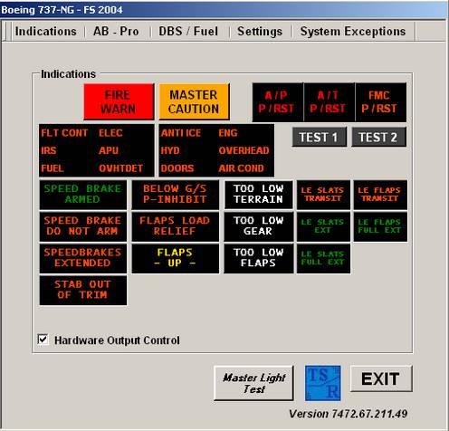
35 TSR Boeing 737-NG AutoBrake Pro Indications Page 35
 MASTER CAUTION (Button) FIRE WARN (Light) MASTER CAUTION (Light) RECALL (Button) Output for each Symbol (Light) The complete logic is included but pmsystems (Project Magenta) is as")
36 Indications The following Indications and Sound controls are supported as close to real as possible. FIRE WARN (Button) MASTER CAUTION (Button) FIRE WARN (Light) MASTER CAUTION (Light) RECALL (Button) Output for each Symbol (Light) The complete logic is included but pmsystems (Project Magenta) is as source needed. The pmsystems SixPack logic is NOT relevant for the indication or its internal logic. The supported Offsets (Output and Input) are NOT the Project Magenta ones! That means that e.g. Hardware that uses / supports ONLY Project Magenta s SixPack Offsets for Outputs and Inputs is NOT useable!! At this stage (Hardware / Driver related) e.g. the CPflight s MIP-Board is NOT useable as long you cannot define its Offsets for those Outputs. TEST - 1 TEST - 2 A/P (P/RST) (Light red / Test-1 + logic) A/T (P/RST) (Light red / Test-1 + logic) A/P (P/RST) (Light orange / Test-2) A/T (P/RST) (Light orange / Test-2) FMC (P/RST) (Light orange / Test-1/2 + logic) A/P (P/RST) (Button + Disarm controlled (double signal like real)) A/T (P/RST) (Button + Disarm controlled (double signal like real)) FMC (P/RST) (Button) TEST 1 (Button) TEST 2 (Button) SPEED BRAKE ARMED (Light) SPEED BRAKE DO NOT ARM (Light) SPEEDBRAKES EXTENDED (Light) Page 36
 (The possible Sound Inhibit is NOT real but for those ones the like or need to inhibit each sound while active) GPWS - Mode 5 BELOW G/S (Light)")
37 GPWS Mode 4 (4A + 4B) TO LOW TERRAIN (Light) TO LOW GEAR (Light) TO LOW FLAPS (Light) TO LOW TERRAIN (Sound control, to Inhibit by Offset Bit) TO LOW GEAR (Sound control, to Inhibit by Offset Bit) TO LOW FLAPS (Sound control, to Inhibit by Offset Bit) (The possible Sound Inhibit is NOT real but for those ones the like or need to inhibit each sound while active) GPWS - Mode 5 BELOW G/S (Light) BELOW G/S (Button to Inhibit sound, self reactivation by logic) BELOW G/S (Sound control) Indicates the actual Flaps setting when controlled by TSR Boeing 737-NG FLAPS LOAD RELIEF (Light) is an Option to Boeing 737 s (not standard equipment). To get it work it is needed to let the program controls the whole Flaps system. You need just to define your Flaps Lever with its 9 positions (0Ü to 40Ü) to a special Offset (value 0 to 8), so the program controls instead the Flaps and of course the Flaps Load Relief function. This full controlled system contains Indicates LE SLATS/FLAPS Positions when controlled by TSR Boeing 737-NG - TE FLAPS control - LE SLATS control - LE FLAPS control - Autoslats system (in advanced of STALL) - Alternate Flaps system (no Hydraulic B) The system is very complicate and that s why it is only supported by TSR Boeing 737-NG Flaps full control Mode. So the Flaps are controlled by a separate Offset (Input) and the Alternate Flaps are controlled by pmsystems Alternate Master switch and Alternate Position switch. Indicates STAB OUT OF TRIM when Autopilot is active. The Limit is set in Indication.ini file as e.g. Stab Out Off Trim UP=6000 and Stab Out Off Trim DN= Page 37

38 Boeing 737-NG Display This is a separate program to display any indications controlled by TSR Boeing 737-NG program. You can also control the Boeing 737-NG program with this tool if the needed hardware is not connected or available in your setup. It doesn t display any e.g. pmsystems controlled indications! The panel can be placed above (overlapped) of any other program like PFD / ND / EICAS / Different groups of the indications are hide able, so you can decide what should be displayed on the screen where it is installed. It is possible to install multiple copies in your network to display different indications on different screens. Program controls Shift + T move UP Shift + B move DN Shift + F move LEFT Shift + H move RIGHT Shift + + size increase Shift + - size decrease Shift + Q program close In Boeing737NG Display.ini file you can change the different settings Hardware =Yes this is set to Yes if you want to control the Buttons with the Mouse (no hardware is used) TopMost =No This sets the program into foreground when Yes is used The following settings enables / disables the different indication groups. {Visible Indications} SixPack =Yes Flaps =Yes AFDS Indication =Yes TOO Low... =Yes Autobrake =Yes Speed Brake =Yes Page 38

 Flaps Auto Config, activates the self teaching system for needed Flaps position. Is needed for Flaps Control but as well for normal work.")
39 Settings Here we control the important settings for AutoBrake Pro and other logic. Hardware Connected, connects just the Offsets to its functions TSR SixPack, activates the internal SixPack logic / System No APU / Refill / Tank Leak, deactivates this internal logic system Below G/S Switch, activates the internal logic / handling when a physically hardware button is available for this function (Inhibit Callout while active) Flaps Control, activates the internal Flaps logic and handling (needed for FLAPS LOAD RELIEF function) Flaps Auto Config, activates the self teaching system for needed Flaps position. Is needed for Flaps Control but as well for normal work. While pressing Flaps Auto Config the system teaches itself to get any needed Flaps position. It will take may be up to one minute to Finish and saving the corresponding values. Important is that your used A/C is defined to 9 Flaps positions, 0 /1 /2 /5 /10 /15 /25 /30 /40 deg. Any other settings are related to AutoBrake Pro B737 and are described in its own part above (AutoBrake Pro), page Page 39

40 APU Fuel consumption / Tank refill / Tank Leak It is a controller program and Tank refill program, designed to use it together with pmsystems and its 737 logic ONLY. 1. It controls the Fuel consumption of the APU for 737, depending of the Fuel Tank selection for the APU. The APU can use fuel from Center tank or Left main tank. If left Center pump is ON the APU consume fuel from the Center tank, else the left Main tank is used. In any case the APU can only consume fuel if NO engine consume fuel from the selected Tank, to don't bother the engines consume. With the slider you can control the consumption for the selected Tanks, left Main or Center Tank. 2. You know there is a panel above the Bus-display named "Auxiliary Fuel Transfer" without a function. Now you can refill the Tanks with this switches, of course it takes a bit time like in real! To refill --> Both engines Cutoff Park brake set Extern Power connected and Bus connected You can refill the Left and Right Main tank separate or together. If both Main tanks are filled to 100% and both switches are ON, then the Center Tank becomes filled. It takes again time. If you switch to OFF the refilling will stops. You can refill by SetBit (Start) / ClrBit (Stop) in Offset 0x56B3. Left refill = Bit 4 Right refill = Bit 5 3. You can simulate loss of fuel by SetBit (Start) / ClrBit (Stop) in Offset 0x6DB8 Center Tank = Bit0 L-Main Tank = Bit1 R-Main Tank = Bit2 Page 40

41 System Exceptions Here you can select or disable included systems logic. If you want to use the build in Bleed / Pack System make sure you removed the corresponding lines in the logic file (.lgc), check pmsystems changes page. Page 41
 means that you can set any indication to blink mode by clicking direct on it.")
42 Hardware Output Control To activate this function just check the Box below and the system goes into Check-Mode. Ckeck-Mode (Hardware Output Control) means that you can set any indication to blink mode by clicking direct on it. The corresponding Output Offset is then as well in blink modus and you can check your connected hardware for its correct working. The blink modus will stop if you cklick again on the decided indication. Further information s about the decided indication Offset you will get if you move the mouse above the indication, Hardware Output Control needs to be checked. Page 42
43 Boeing 737-NG.ini / Flaps.ini / Indication.ini / Scrubbing.ini In this files there are all settings saved you did in the program or need to change also manually. 1. Boeing 737-NG [Boeing 737-NG ] [Logic Settings] A/C Version B737 - =600 Hardware Connected =NO TSR - SixPack =YES MasterLight hdw =NO Analog Cutoff Lever =NO No APU/Refill/Leak =NO BELOW G/S Switch =YES FLAPS CONTROL =YES //FOS-8 [AutoBrake Pro] No Analog Toe Brake =YES No Different. Brake =NO Use Offset 0x6DB1 =YES WXR Manual Set =NO Sound Output =NO CycleTime =50 Toe Base =71 Press High =67 Press Low =25 Skid Factor =7 PM-SIMULATOR =NO AT/Dis. Offset 050A =YES [pmfmc - Path] FMC Main Path NAV Date = [System Exceptions] No IRS Handling =YES No Drive Switches =NO //FSE-3 Simple APU is used =YES No Logic =YES No Indicators =NO No SixPack =NO //FSE-8 //FSE-9 //FSE-10 //FSE-11 //FSE-12 //FSE-13 //FSE-14 //FSE-15 //FSE-16 //FSE-17 //FSE-18 //FSE-19 //FSE-20 =\\AMD-HARDWARE\pmCDU [Fuel Handle] Center =1058 Left =590 Wing Refill =150 Cent Refill =150 [Screen Settings] Position - X =722 Position - Y =143 // Sets the Fuel used for Center-Tank, 10 <-> 1600 // Sets the Fuel used for Left-Tank, 10 <-> 1600 // Refill Rate 20 <-> 200, default 150 // X/Y = 0 <-> 1100/750, default 10 The red market lines are without any meaning for you! Page 43
44 2. Flaps.ini The Flaps Position settings are done by the program itself in teach modus. The only settings that you can change if needed is the Flaps Speed setting for Flaps 30 and Flaps 40 which is the reference for FLAPS LOAD RELIEF function. [Flaps Position/Speed 0-40] Flaps Position - 0 =0 Flaps Position - 1 =2047 Flaps Position - 2 =4095 Flaps Position - 5 =6143 Flaps Position - 10 =8191 Flaps Position - 15 =10239 Flaps Position - 25 =12287 Flaps Position - 30 =14335 Flaps Position - 40 =16383 Flaps Speed - 30 =176 Flaps Speed - 40 =163 Flaps Lever - 0 =0 Flaps Lever - 1 =1 Flaps Lever - 2 =2 Flaps Lever - 5 =3 Flaps Lever - 10 =4 Flaps Lever - 15 =5 Flaps Lever - 25 =6 Flaps Lever - 30 =7 Flaps Lever - 40 =8 3. Indication.ini The FLAPS POS. 5 / 10 / 15 Deg. Settings are done by the program itself in Teach modus. [Indication Settings] G/S ARMED ALTITUDE =1800 G/S MIN ACTIVE =60 FLAPS POS. 1 Deg. =409 FLAPS POS. 2 Deg. =819 FLAPS POS. 5 Deg. =2047 FLAPS POS. 10 Deg. =4095 FLAPS POS. 15 Deg. =6143 // Sets the ARMED Altitude (ft), 1000 <-> 2000 (default 1000) // Sets the G/S MIN deviation, 45 <-> 85 (default 60) // Sets the Flaps Value of Offset 0x0BE0 for Page 44
45 4. Scrubbing.ini The settings are described in AutoBrake Pro Scrubbing.ini file settings above. But the difference is that there are now settings for each weather condition. They have all a base setting but can be changed to your needs by yourself. [Boeing 737-NG] [Condition DRY] 7 kts = kts = kts =1550 [Condition WET] 7 kts = kts = kts =1450 [Condition WET 6mm] 7 kts = kts = kts =1400 [Condition SLUSH 6mm] 7 kts = kts = kts =1390 [Condition SLUSH 13mm] 7 kts = kts = kts =1370 [Condition SNOW 5cm] 7 kts = kts = kts =1350 [Condition ICE] 7 kts = kts = kts = Page 45
46 TSR Electronic Checklist The Electronic Checklist brings you to no paper need!! Create Your Own Checklists!! The Electronic Checklist is a nearly full automatic Checklist system that checks all available clear settable positions and settings in the decided Checklist, in B737 Mode when pmsystems is connected only. In Customer Mode you can create your own needed Checklist, up to 20 Checklists with 50 Points for each! The Electronic Checklist is by Key / Offset (registered FSUIPC) / Control Panel settable to VISIBLE / HIDE, so you can switch it to ON / OFF to don t have it as interference factor in view. B737 Mode, pmsystems is connected. The Pilot needs to set the requested Configurations and when the request is fulfilled the next Checklist Point will be selected by automatic. B737 Manual Mode, pmsystems is NOT connected / needed. The Pilot needs to set the requested Configurations if available and needs to mark the Checklist Point as CHECKED; the next Checklist Point will be selected by automatic. Customer Mode, it just works as a STAND ALONE application on any PC (Framework 2.0 needed). You are able to create your own Checklists with your to your fulfills. - up to 20 Checklists - up to 50 Checklist points per Checklist - useable for ANY Aircraft - useable e.g. for ONLINE FLYING to create your Online-Flying-Checklists, you will never forget your important things to do and your Controller will be amazed! It is easy to handle with a lot of options to control. Supported system B737 Supports Customized Checklists created by yourself for Your needs or different A/C s! Auto Check or Manual Check selectable - Auto Check, detects pmsystems (default logic file) and needed FS status information - Manual Check, if NO pmsystems is used or in a different configuration use full Keyboard control full Mouse control full Offset control via FSUIPC/WideFS separate Control Panel, installed on a different PC via FSUIPC/WideFS Hide / Visible status to be visible overlapped of e.g. ND display or another Display. Resize-able up to 1280 x 1024, Position and Size is saved. Font size, Color (white or green) and Bold is set-able each Checklist can be cleared, one or multiple Page 46
, one or more Checklist(s) can be cleared www.")
47 TSR Electronic Checklist overlapped of ND display It contains the following Checklists / Function for B737 RECEIVING COCKPIT BEFORE ENGINE START CLEARED FOR ENGINE START ENGINE START AFTER ENGINE START BEFORE TAKEOFF CLEARED FOR TAKEOFF AFTER TAKEOFF DECENT APPROACH LANDING AFTER LANDING PARKING TERMINATION CLEAR CHECKLIST(S), one or more Checklist(s) can be cleared Page 47
48 Create your own Checklists for your needs or different A/C s. Page 48

49 Control Panel to control the Electronic Checklist from a different PC by using the mouse The system in Autocheck mode waits for minimum APU EGT to set the CHECKED status Page 49


50 Autocheck Mode is OFF, Font colour white Menu by pressing ESC Key Page 50
51 Settings Here you are able to set very important options they are needed for YOUR Cockpit setup. [Electronic-Checklist] {CODE} xxxxxxxx Size-X = 366 Size-Y = 260 Position-X = 1037 Position-Y = 178 Font Size = 8 A/C System = 737 Electronic-Checklist.ini file [Options] Offset Hide = Yes TSR AutoBrk = No NO FSUIPC = No // FSUIPC is not registered or pmsystems is not used // Is set to Yes if a unregistered version of FSUIPC is running AutoCrs OFF = No // Switch Auto Cursor Function, one Down, to OFF Font BOLD = Yes // Sets the Font to BOLD Font WHITE = No // Sets the Font to WHITE instead of GREEN # 6 = No // Future setting # 7 = No // Future setting [System Exceptions] NO Oxygen Switch = No NO IRS Selectors AFT = No NO PWR/OVHT Test = No NO FS-GEN-BUS = No NO CTR-1/2 PumpCheck = Yes A/C System = is used for the internal Checklist for B737. Any other is used for your own created Checklist, e.g. DC10. In this case the name of your own Checklist file would be DC10.ini Options Offset Hide, sets the program to Visible / Hide function by using the Offset 6DB3, Bit3 only TSR AutoBrk, sets the program to use the Offset 6DB1, 1 Byte length instead of the FS Offset NO FSUIPC, disables the use of FSUIPC and sets the program to Manual Check mode for all checklists System Exceptions NO Oxygen Switch, there is NO Oxygen switch in your After Overhead panel connected so it is to check manually NO IRS Selectors, there are NO IRS Selectors in your After Overhead panel connected so it is to check manually If there are Customer needs, more can be included! Page 51
52 Program Control The Control Panel can be placed somewhere on a different PC in your Network than the Electronic Checklist is installed to control it as well by mouse, FSUIPC / WideFS connection is needed. In Electronic-Checklist.ini file you need to set the following Option to YES. [Options] Offset Hide = Yes Key Control The used Keys to control the program on that PC where it is installed and the program has focus, are as follows. Cursor UP / DOWN, to go up and down in the menus ENTER - to select the Checklist or on symbol to go to previous menu - to CHECK manual selection in the Checklist - to select in CLEAR CHECKLIST the Checklist (s) as deleted (cleared to UNCHECKED / TODO) SCROLL / LOCK, to HIDE / VISIBLE the Electronic Checklist on the screen ESC Key, to get into Windowed mode for move and resizing the panel. By pressing again ESC Key the program switches back to normal screen CTRL + Q Key, to close the program Mouse Control By using the mouse to control the program just click on the functions you want to. Offset Control Here are the used Offsets to control the program by hardware or direct from the FS-PC with FSUIPC Key or Button (e.g. Joystick Buttons) programming. Cursor UP / DOWN Offset 6DB3 Bit0 Cursor UP / Bit1 Cursor DN ENTER Offset 6DB3 Bit2 Cursor ENTER - to select the Checklist or on symbol to go to previous menu - to CHECK manual selection in the Checklist - to select in CLEAR CHECKLIST the Checklist (s) as deleted (cleared to UNCHECKED / TODO) SCROLL / LOCK, Offset 6DB3, Bit3 = Checklist Visible / Hide - to HIDE / VISIBLE the Electronic Checklist on the screen ESC Key, to get into Windowed mode for move and resizing the panel. By pressing again ESC Key the program switches back to normal screen CTRL + Q Key, to close the program Page 52
53 User Defined Checklists This is an example of two user defined Checklists, TEST-1 and TEST-2. Page 53
54 To create your own Checklist you need to follow exactly this regulate!! You will find a base example file, User100.ini, in the main folder. The File name has to be changed in the Electonic- Checklist.ini to your own created file name e.g. A/C System = DC10 In this case the name of your own Checklist file would be DC10.ini 1. Line = number of checklist items (subfolders), here we use 3 (TEST-1, TEST-2 and TEST-3). Possible value is 25, so there are 25 Checklists to define if needed. 2. Line = number of included lines for the first Checklist, this is needed for each Checklist! Here we use 5 because our first Checklist has 5 check items. 3. Line = number of included lines for the second Checklist, see above! 4. Line = number of included lines for the third Checklist, see point above 2.! This lines You have to do for all Checklists you want to define, e.g. you want define 5 Checklists with 4, 8, 20, 12 and 20 Check items, so you need to write the following in this first part 5 defines 5 Checklists 4 defines 4 Checklist items for the first Checklist 8 defines 8 Checklist items for the second Checklist 20 defines 20 Checklist items for the third Checklist 12 defines 12 Checklist items for the forth Checklist 20 defines 20 Checklist items for the fifth Checklist Then it has to follow a blank line Now you write the Headline, name of the Checklist (here TEST-1) Then the above defined 4 Checklist items have to follow. This part has to be done for each Checklist, ever starts with a blank line (space holder). VERY IMPORTANT is that you use the style of 32 letters for each line (Headline and Check items), if not the Checklist will look a bit chaotic. So just fill ever shorter lines with space or dots like below, that s why I changed the back colour to display the writing structure TEST-1 Speedbrake... ARMED & GREEN. Gear......DOWN & 3 GREEN. Flaps SET & GREEN. NAV Display SET. Course Arrow... AS REQUIRED. TEST-2 Anti-Ice..... AS REQUIRED. Trim Air Switch OFF. Press AS REQUIRED. ENG-1 Starter OFF. ENG-2 Starter OFF. APU AS REQUIRED. Exterior Lights.. AS REQUIRED. Autobrake OFF. Speedbrake.... DOWN DETENT. Flaps UP. Radar OFF. Transponder OFF. Landig Lights OFF. Taxi Lights ON. TEST-3 Anti-Ice OFF. Trim Air Switch ON. Press OFF. Page 54

, but needs to be Togglebits without Control sent when main Key released definition!")
55 Manual Changes in FSUIPC Module 4) For Key Control on FS-PC to control the program over the Network 5) For Button Control with Joystick to control the program over the Network, just use instead the Buttons + Switches section for set up. Using the Offset 6DB3, 1 Byte length - Cursor Up = Bit0 (Parameter x01) - Cursor Down = Bit1 (Parameter x02) - Enter = Bit2 (Parameter x04) - Display Hide/Visible = Bit3 (Parameter x08), but needs to be Togglebits without Control sent when main Key released definition!! Setting in FSUIPC for Cursor UP, Bit0 (2^0 = 1) Setting in FSUIPC for ENTER, Bit2 (2^2 = 4) Page 55
 is running it recognized each switch state change and plays a sound.")
56 TSR B737 SwitchSound The B737 SwitchSound lets you hear on each switch state change on the B737 Overhead Panel a switch sound. This software is for those they use e.g. a Touch Screen for the overhead panel and need to hear that a switch has been really touched. The program starts minimized and connects to WideClient or FSUIPC direct. When pmsystems (Project Magenta) is running it recognized each switch state change and plays a sound. There are 4 different sound defined you can change in its ini file. [TSR B737 SwitchSound] Sound file Switch Normal =switch_large Sound file Switch Center =switch_large Sound file Switch Rotary =switch_rotary Sound file Switch Button =switch_small The attached sound files are taken from FS9 (Microsoft á Flight Simulator 2004) as examples and are not part of the software. To change the sound files just write the new name (without.wav ) in the corresponding line. Normal = there are normal switches with ON / OFF position defined Center = there are switches with a center position defined Rotary = there are rotary switches like the engine starter switch defined Button = there are momentary button switches like Groundcall defined Page 56

57 ICAO Position It is this one is required or contained around a program addition as of Boeing 737- NG version Far more than 26,000 airport positions have been saved internally with corresponding ICAO codes for each Flight Simulator, FSX and FS2004! With this additional program, what will be opened and closed by TSR AutoBrake program automatically you can for your needed airports define for its corresponding landing directions RWY conditions. Conditions means here that the braking acceleration counted in TSR AutoBrake will be in addition increased or decreased up to 40%. There can be e.g. RWY s with slope or downward slope (like Lukla) or just good or bad surface simulated, they are actually not available in FS. After opening the ICAO.txt file by clicking on Open ICAO.txt by following the exact syntax values are inserted or changed. [ICAO],[direction],[factor] factor 00/10=norm, 01-09=bad/sloped negative, 11-20=good/sloped ICAO = the ICAO of airports, e.g. VNLK for Lukla. For installed Lukla Scenery from Aerosoft use also the default ICAO VNLK. Direction = landing direction, for Lukla e.g. for runway 06 we write 06 for 60 deg. Or for landing direction 180 deg the value 18 is written. Factor = slope / downward slope / good surface / bad surface, for Lukla e.g. for landing direction 06 what is a extreme slope we defined the value 15. Applies to Factor: The value of 10 or 00 is the normal value what is NOT to define because it is used automatic when nothing is defined. Values of 01 to 09 define a downward slope or a bad surface that prolong the braking distance. 01 is staying for the worst value. Page 57
WELCOME TO. 737 NG TQ Pro Motor. Version May 2015
 WELCOME TO 737 NG TQ Pro Motor Version 1.2.4 May 2015 INDEX 1 INTRODUCTION 2 2 INSTALLATION 3 3 USING THE TQ IN X-PLANE 5 4 USING THE TQ IN FS9, FSX, ESP AND Prepar3D 6 5 CONFIGURING TQ THROTTLE FOR FIRST
JetMax Throttle Installation Instructions
 JetMax Throttle Installation Instructions 1 The JetMax 737 Throttle unit is designed to bring our customers a highly realistic looking device that covers all the basic requirements needed! Features Include:
737 NG TQ Pro / Motor
 WELCOME TO 737 NG TQ Pro / Motor Version 1.2.9 December 2017 INDEX 1 INTRODUCTION 2 INSTALLATION 3 USING THE TQ IN X-PLANE 4 USING THE TQ IN FS9, FSX, ESP AND Prepar3D 5 CONFIGURING TQ THROTTLE FOR FIRST
FSUIPC Offsets for Wilco Airbus Volume 1 & Volume 2
 FSUIPC Offsets for Wilco Airbus Volume 1 & Volume 2 The FSUIPC Export module provides access to all the Wilco Airbus information through FSUIPC offsets. This module is available for FS2004 and FSX. The
COMET SIMULATOR KEYSEND INJECTION PROGRAM NOT TO BE REMOVED FROM COCKPIT
 COMET SIMULATOR KEYSEND INJECTION PROGRAM NOT TO BE REMOVED FROM COCKPIT Table of Contents Introduction... 3 Navigation column... 4 FSX Sub Menu... 5 POSITION Sub Menu... 7 COMET Sub Menu... 8 FAILURES
FSUIPC Basics. The basics on how to assign flight simulator functions to buttons, switches and axis.
 FSUIPC Basics The basics on how to assign flight simulator functions to buttons, switches and axis. Flight simulator can be so much more realistic if we could assign more realistic functions to buttons,
V737 Overhead. VRinsight
 VRinsight Contents 1. Introductions 1.1 General.... 1.2 Features... 2. Deliverables 3. Hardware Connection 3-1. and wing stand assembly... 3-2. USB / POWER / LED connection. 4. Software installation 4-1.
P r e c i s i o n F l i g h t C o n t r o l s, I n c. S e r i a l C A T I I I a n d F S X S y s t e m S e t u p G u i d e
 P r e c i s i o n F l i g h t C o n t r o l s, I n c. S e r i a l C A T I I I a n d F S X S y s t e m S e t u p G u i d e (Shown with optional Garmin 430) Preface This setup guide will walk you through
Configuring the B737 Throttle Quadrant for Flight Simulator Use
 I ve received several questions asking for more concise information detailing how the real B737-300 throttle quadrant is configured to operate within the FSX environment. Before I begin, let me state that
C A T I I S y s t e m a n d F S X. S e t U p G u i d e
 C A T I I S y s t e m a n d F S X S e t U p G u i d e Preface This setup guide will walk you through the necessary steps to setup your CAT II System with Microsoft Flight Simulator X. For connection diagram,
AEROSOFT. Aerosoft Australia Introduction. MCP Overview. About Us. What is it and what does it do? What simulation software interfaces with it?
 Aerosoft Australia Introduction About Us Aerosoft Australia has been developing products since the early 1990 s and is located in Sydney Australia. The first software title produced was for night VFR training
ECLIPSE 500. Flight Controls. Do Not Use For Flight
 ECLIPSE 500 Flight Controls Do Not Use For Flight 3. Flight Controls 3.1 General The flight control system consists of primary flight controls (ailerons, rudder, and elevator) and secondary flight controls
QUALIFICATION TEST STUDIO
 V1.02 2016 October Tool for Master and Recurrent Qualification Test (MQTG/RQTG) for FNTP certification simulators based on Flight Simulation / PREPAR3D http://www.fsinstructor.com Dan Guimbert contact@fsinstructor.com
MJC8Q400, Special Features guide
 MJC8Q400, Special Features guide This special features guide describes the functionality which is addon-specific and is not found in the system or flight tutorial. Switches and knobs All the switches and
Contents: Introduction Page Hardware...Page Connecting Inputs and Outputs..Page Software.Page 6
 Contents: Introduction Page 3 1. Hardware...Page 4 2. Connecting Inputs and Outputs..Page 5 3. Software.Page 6 4. Testing Connected Inputs/Outputs Page 7 5. Configuring Digital Inputs Page 8 6. Configuring
REALTRIM PROFESSIONAL
 VERSION [2.0.0.0] REALTRIM PROFESSIONAL PRESENTED BY: KURT KÄFERBÖCK THIS MANUAL WAS COMPILED FOR USE ONLY WITH THE REAL TRIM SOFTWARE FOR MICROSOFT FLIGHT SIMULATOR X. THE INFORMATION CONTAINED WITHIN
PMDG 777 CUSTOM EVENT ID's
 PMDG 777 CUSTOM EVENT ID's for use with FSUIPC and FSX, FSX-SE or Prepar3D* SP1c Cockpit Builder Edition is a free service of www.myhomecockpit.de www.flightm.com 2015 Flight! Magazin - A.Giel PMDG 777
USER S MANUAL SOLO Airliner. User s Manual
 User s Manual Rev 1.1 July 2016 TABLE OF CONTENTS 1. IDENTIFICATION OF ELEMENTS 2. INSTALLATION 3. START UP 4. SELECTION OF PANEL TYPE (according to plane) 5. ENGINE STARTING 6. SIMULATING THE BOEING 737
FDS-PRO-MX-CDU/MCDU 2013 Ver 1.6 Page 1
 FDS-PRO-MX-CDU/MCDU 2013 Ver 1.6 Page 1 INDEX Features... 3 Compatible Software List... 4 FDS-CDU Software Modules and Setup... 7 Sim-Avionics Setup...11 NAV DATA...16 Air Sim Tech (AST) Setup...17 Project
P r e c i s i o n F l i g h t C o n t r o l s, I n c. S e r i a l C A T I I I S y s t e m a n d F S S e t u p G u i d e
 P r e c i s i o n F l i g h t C o n t r o l s, I n c. S e r i a l C A T I I I S y s t e m a n d F S 2 0 0 4 S e t u p G u i d e Preface This setup guide will walk you through the necessary steps to setup
B737 NG MOTORIZED THROTTLE SETUP MANUAL PROJECT MAGENTA. Revolution- Simproducts. All Rights Reserved
 B737 NG MOTORIZED THROTTLE SETUP MANUAL PROJECT MAGENTA Revolution- Simproducts All Rights Reserved January 9, 2010 1 CONTENT INTRODUCTION...3 REVISION LIST...4 Installation for PM without any previous
1.- Introduction Pages Description 19.- Tutorial 20.- Technical support
 FriendlyPanels Software WARNING This operating manual has been written to be used only with Microsoft Simulator. FriendlyPanels www.friendlypanels.net fpanels@friendlypanels.net Flight Table of Contents
S e r i a l T h r o t t l e Q u a d r a n t C o n s o l e S e t u p G u i d e W i t h M i c r o s o f t F l i g h t S i m u l a t o r X
 S e r i a l T h r o t t l e Q u a d r a n t C o n s o l e S e t u p G u i d e W i t h M i c r o s o f t F l i g h t S i m u l a t o r X Preface This setup guide will walk you through the necessary steps
MCP737PRO (THIS MANUAL IS SUITABLE FOR THE MCP737PRO VERSION)
") CPflight OPERATIONS MANUAL MCP737PRO (THIS MANUAL IS SUITABLE FOR THE MCP737PRO VERSION) This manual is intended for Flight Simulator use only and may not be used in any real world aviation application.
CPflight OPERATIONS MANUAL MCP737PRO (THIS MANUAL IS SUITABLE FOR THE MCP737PRO VERSION) This manual is intended for Flight Simulator use only and may not be used in any real world aviation application.
Turbo 310R. X-Plane user guide
 Turbo 310R X-Plane user guide This software is an artistic representation of the subject matter. Any similarities to any commercial product, equipment, vehicle, device or other, present within this artistic
This manual is intended for Flight Simulator use only and may not be used in any real world aviation application. The authors are not responsible for
 CPflight OPERATIONS MANUAL This manual is intended for Flight Simulator use only and may not be used in any real world aviation application. The authors are not responsible for any errors or omissions.
SETUP GUIDE/MANUAL FDS PRO-MX-CDU/MCDU
 SETUP GUIDE/MANUAL For FDS PRO-MX-CDU/MCDU FDS CDU Setup/Manual v1.9 January 3, 2018 Page 1 of 33 Contents 1.0 Product Information 4 2.0 Compatible Software List 5 3.0 Features 6 4.0 FDS-CDU Software Installation
Programming the FDS-SYS1X Interface card in ProSim737:
 Programming the FDS-SYS1X Interface card in ProSim737: Programming the FDS-SYS1X card for use with the ProSim737 software is not so difficult as it looks. In this example, I will program the Aft 1 Fuel
USER S MANUAL Solo Flight Panel. User s Manual. Rev 1.6 October VirtualFly, S.L. tel
 User s Manual Rev 1.6 October 2015 1 TABLE OF CONTENTS 1. IDENTIFICATION OF ELEMENTS 2. INSTALLATION 3. START UP 4. SELECTION OF PANEL TYPE (according to plane) 5. ANALOGIC PANEL INDICATORS 6. RADIOSTACK
INSTALLATION MANUAL FOR USING YOUR THROTTLE V3. Version
 INSTALLATION MANUAL FOR USING YOUR THROTTLE V3 Version 1.6.40 23. Aug. 2 0 1 7 w w w. c o k c p it f o r y o u. c o m To r s t en M ü ll e r Installation manual for using your TQ Thank you for purchasing
Connecting Your Rudder Potentiometers to The BU0836 Controller Card.
 Connecting Your Rudder Potentiometers to The BU0836 Controller Card. There are 3 Potentiometers fitted to the rudder pedals. Left Brake, Right Brake and the Rudder itself. This is how to connect them to
Professional Simulator Suite. User Manual version 1.0. ProSim Aviation Research B.V. Rotterdamseweg 388D 2629 HG Delft The Netherlands
 ProSimA320 Professional Simulator Suite User Manual version 1.0 ProSim Aviation Research B.V. Rotterdamseweg 388D 2629 HG Delft The Netherlands Website: www.prosim ar.com Email: info@prosim ar.com Phone:
MCP737EL. THIS MANUAL IS SUITABLE FOR THE MCP737EL version
 CPflight OPERATIONS MANUAL MCP737EL THIS MANUAL IS SUITABLE FOR THE MCP737EL version This manual is intended for Flight Simulator use only and may not be used in any real world aviation application. The
Wilco Airbus Software Module for VRInsight CDU II
 No mouse click generation, no need to store flight files, no FSUIPC required This software is intended to have the VRInsight CDU II working seamlessly with the Wilco Airbus Series Volume 1 and Volume 2.
USER S MANUAL Duo Flight Panel. User s Manual. Rev 1.0 June VirtualFly, S.L. tel
 User s Manual Rev 1.0 June 2015 1 TABLE OF CONTENTS 1. IDENTIFICATION OF ELEMENTS 2. INSTALLATION 3. START UP 4. SELECTION OF PANEL TYPE (according to plane) 5. ANALOGIC PANEL INDICATORS 6. RADIOSTACK
FSXThrottle All Quadrants (all models) Notes*
 Notes*") FSXThrottle All Quadrants (all models) Notes* * Please note that not all features and options described or listed in these notes may apply to your model. Table of Contents Introduction:...3 Our Commitment:...3
FSXThrottle All Quadrants (all models) Notes* * Please note that not all features and options described or listed in these notes may apply to your model. Table of Contents Introduction:...3 Our Commitment:...3
JoinFS v1.1.4 (STABLE) Setup and Configuration
 Setup and Configuration") JoinFS v1.1.4 (STABLE) Setup and Configuration January 28, 2017 Note that unless you are testing or otherwise investigating possible additional functions of JoinFS it is recommended that you use the current
JoinFS v1.1.4 (STABLE) Setup and Configuration January 28, 2017 Note that unless you are testing or otherwise investigating possible additional functions of JoinFS it is recommended that you use the current
Flight Training Device ATS-A320 Appendix B) Components Description Reviewed:
 Components Description Reviewed:") Model Serial Number Tail Number ATS-A320 Operator Setup and instrument description of the Advanced Training System (ATS) A320, which includes the following sections, modules and instruments to simulate
Model Serial Number Tail Number ATS-A320 Operator Setup and instrument description of the Advanced Training System (ATS) A320, which includes the following sections, modules and instruments to simulate
VP- X Pro & VP- X Sport
 VP- X Configurator Release Notes As of version 1.6 (May 13, 2013) This document updated October 31, 2013 Contents 1. Models...1 2. Updating the VP-X Pro and Sport firmware (Automatic)...1 3. Software Upgrade
Su-25T. Key Command List
 Su-25T Key Command List General Esc End mission Pause Pause Z - LCtrl Time accelerate Z - LAlt Time decelerate Z - LShift Time normal ' Score window ` Multiplayer chat - mode All ` - RCtrl Multiplayer
LRM Client User Manual. v Copyright Bobby Allen
 LRM Client User Manual v4.0.0 Copyright 2014 2017 Bobby Allen TABLE OF CONTENTS Table of Contents... 2 About... 3 System requirements... 4 FSX and P3D Users...4 X-Plane Users...4 Using both FSX/P3D and
Working with the DTC. DTC files and locations
 Working with the DTC In real life, missions are planned on a normal computer or laptop. This data needs to be taken to the aircraft and loaded into the mission computer of the F-16. This is done with the
MiG-29 (MiG-29G) Key Command List
 Key Command List") MiG-29 (MiG-29G) Key Command List General Esc End mission Pause Pause Z - LCtrl Time accelerate Z - LAlt Time decelerate Z - LShift Time normal ' Score window ` Multiplayer chat - mode All ` - RCtrl Multiplayer
MiG-29 (MiG-29G) Key Command List General Esc End mission Pause Pause Z - LCtrl Time accelerate Z - LAlt Time decelerate Z - LShift Time normal ' Score window ` Multiplayer chat - mode All ` - RCtrl Multiplayer
USER S MANUAL SOLO PRO. User s Manual. Rev 1.1 June VirtualFly, S.L. tel
 User s Manual Rev 1.1 June 2016 1 TABLE OF CONTENTS 1. IDENTIFICATION OF ELEMENTS 2. INSTALLATION 3. START UP 4. SELECTION OF PANEL TYPE (according to plane) 5. ANALOGIC PANEL INDICATORS 6. RADIOSTACK
 PREFACE This is a Dummies Guide. It is NOT the Help File found in Control Manager. Not all subjects will be discussed in as great detail as you would find in the Help File. However, The Dummies Guide will
FMX/MCX Peripheral Calibration Process
 FMX/MCX Peripheral Calibration Process 1. Opening the Windows Game Controllers window A: Plug the USB keyboard into the Pilot Key USB slot in the cabin. B: Hold the Windows ( ) key and tap the R key to
AUTOTHROTTLE AND AUTOPILOT AUTOMATIC DISENGAGE.
 AUTOTHROTTLE AND AUTOPILOT AUTOMATIC DISENGAGE http://www.md80project.dk http://sites.google.com/site/danskemd80cockpitprojekt/ The parts needed for this build is: Input Output Optocoupler LTV 817 (Or
Connecting Opencockpits modules in ProSim737
 Connecting Opencockpits modules in ProSim737 Introduction page 2 SIOC script file page 3 SIOC.INI file page 4 Connecting your MCP page 5 Connecting your first EFIS page 11 Connecting your second EFIS page
Wagner Smart Screen Service/Troubleshooting Screens
 Section 7-2 Wagner Smart Screen Service/Troubleshooting Screens Menu Button PIN code login When you fi rst click on the Menu button, you will be prompted for a PIN code. Enter 0070 and click the check
Installing the Twin-Engine Saitek Pro Flight Quadrant
 Installing the Twin-Engine Saitek Pro Flight Quadrant by Claudio Cloudy Di Veroli, published in PC FLIGHT, The Official magazine of the PC Pilots Ireland, Jun 2013, pp. 23-25 Installing, customising and
OVH737 (OVH737FWD & OVH737AFT)
") CPflight OPERATIONS MANUAL (FWD & AFT) This manual is intended for Flight Simulator use only and may not be used in any real world aviation application. The authors are not responsible for any errors or
CPflight OPERATIONS MANUAL (FWD & AFT) This manual is intended for Flight Simulator use only and may not be used in any real world aviation application. The authors are not responsible for any errors or
2019/02/02 08:15 1/2 Settings
 2019/02/02 08:15 1/2 Settings Table of Contents Settings... 1 Simulator Related Settings... 1 Simulator... 1 Select Simulator Type... 1 Simulator Settings for Prepar3D/FSX/FSW... 2 Simulator Settings for
USER MANUAL (MEH OCT09A) Please read this manual before operating your units and keep it for future reference. VRinsight
 Please read this manual before operating your units and keep it for future reference. VRinsight") USER MANUAL (MEH2.520-26OCT09A) Please read this manual before operating your units and keep it for future reference. VRinsight Virtual Reality Insight All stated here is subject to change without advanced
USER MANUAL (MEH2.520-26OCT09A) Please read this manual before operating your units and keep it for future reference. VRinsight Virtual Reality Insight All stated here is subject to change without advanced
Manual. LC-16 system. LC-16 Inkjet Printer 1
 Manual LC-16 system LC-16 Inkjet Printer 1 Index ENVIRONMENT. 3 OPERATOR S SAFETY 3 OPERATION SAFETY 3 PART 1 INSTALLATION AND PARAMETER SETTING 4 1) Preparing 4 2) Installation 4 3) Priming 4 4) Parameter
CrgSim Documentation
 CHALK RIVER GRAPHICS CrgSim Documentation Installation and User s Guide Chalk River Graphics 8/30/2016 Implementation and installation documentation for CrgSim. Table of Contents FSX, Prepar3d, and FSX
Fixed Wing Models 45
 Fixed Wing Models 45 FLAP FLAPERON Flap Flaperon Mixer Aileron Rudder Mixer Aileron Differential Mixer The mixer "F-A" allows an adjustable portion of the flap control system to be fed to the aileron channels
APP - Aircraft Performance Program
 Introduction APP - Aircraft Performance Program Introduction APP is an aircraft-performance calculation program, specifically designed to provide a fast and easy way to evaluate aircraft performance. Another
CYCLOPS TORNADO OSD V1.0 manual
 CYCLOPS TORNADO OSD V1.0 manual Thanks for buying and using CYCLOPS OSD series products, please read this manual carefully before use. Installation of connections Important: select Jumper instructions:
IGSS 13 Configuration Workshop - Exercises
 IGSS 13 Configuration Workshop - Exercises Contents IGSS 13 Configuration Workshop - Exercises... 1 Exercise 1: Working as an Operator in IGSS... 2 Exercise 2: Creating a new IGSS Project... 28 Exercise
Simulator General Description
 West Jet 737-200 Full Flight Simulator Technical Description Simulator General Description Operator/Sponsor Location Manufacturer WestJet Airlines Calgary, Canada Reddiffusion, Crawley, UK Original In-Service
AVSIM Commercial FSX Utility Review. GeoApr. Product Information
 AVSIM Commercial FSX Utility Review GeoApr Publishers: Flight 1 Product Information Description: Geo-Reference Approach Plates for FSX. Download Size: 9.62 MB Format: Download Simulation Type: FSX Reviewed
SOFTWARE DC4D MONITOR
 THQtronic SOFTWARE DC4D MONITOR Communication between PC and DigiLSU can be achieved only with the cable USB-TTL from FTDI. Reference TTL-232R-5V-AJ is sold as an option. DC4D Monitor is the same application
FDC Live Cockpit Version 3.12
 FDC Live Cockpit Version 3.12 27th March 2010 CHANGES APPLIED to FDC Live Cockpit version 3.12 1. FIXED a small problem when using FDC alongside PFE where the descent checks could be triggered at the wrong
FSFlyingSchool2010 Voice Command Pack
 FSFlyingSchool2010 Voice Command Pack Manual Web: www.fsflyingschool.com Support: [www.fsflyingschool.com/forum] Forum: [www.fsflyingschool.com/forum] Sales: [sales@fsflyingschool.com] Published: June
MINIMUM EQUIPMENT LIST ATA 34 - NAVIGATION F-27 Mk 050
 F7 Mk 5 MNLFL Version :.9.Sep. 3 of Pitotstatic heads a) Pneumatic primary instruments without standby instruments NUMER INSTALLED NUMER REQUIRED FOR DISPATH REMARKS AND/OR EXEPTIONS 4 * (M) One or both
Opencockpits Modules (OCM) Manual
 Manual") Opencockpits Modules (OCM) Manual for the Level-D 767 Version 10.6.2, February 25, 2015 for Windows Vista, or higher Copyright 2007-2015, Nico W. Kaan, Delft, Netherlands, All Rights reserved. No part
Opencockpits Modules (OCM) Manual for the Level-D 767 Version 10.6.2, February 25, 2015 for Windows Vista, or higher Copyright 2007-2015, Nico W. Kaan, Delft, Netherlands, All Rights reserved. No part
4. How to Connect the Fixture 3-Pin and 5-Pin XLR DMX Connectors:
 TABLE OF CONTENTS 1. Safety Instructions 2. Technical Specifications 3. Installation 4. How to Connect the Fixture 5. DMX512 Configuration 6. DMX512 Connections 7. How to Set the Unit 8. Troubleshooting
Sequoia Falco F.8L Version 1.1 FOR X PLANE VERSION PILOT HANDBOOK. Quick & Dirty Version 1.0 Pretty Revisions to Follow
 Sequoia Falco F.8L Version 1.1 FOR X PLANE VERSI 9.50+ PILOT HANDBOOK Quick & Dirty Version 1.0 Pretty Revisions to Follow For entertainment purposes only, to be used with the X Plane Flight Simlator.
Table of Contents. Part I USB Communication. Part II User Interface. Part III User Settings (Tab Control) DFS-1000 Dataview. 2 File Menu.
 DFS-1000 Dataview. 2 File Menu.") 2 Table of Contents Part I USB Communication 3 1 Important... Information 3 2 Connecting... Controller 3 Part II User Interface 4 1 Overview... 4 2 File Menu... 5 3 Options... Menu 6 4 Help Menu... 6 5
2 Table of Contents Part I USB Communication 3 1 Important... Information 3 2 Connecting... Controller 3 Part II User Interface 4 1 Overview... 4 2 File Menu... 5 3 Options... Menu 6 4 Help Menu... 6 5
Electric Version 1. Programming Guide
 Electric Version 1 Programming Guide 3-1-2018 This manual covers the setup and configuration of the Sound Components of the WOWSound Electric decoder. All NMRA, Lighting, and Motor Control programming
Hardware Interface. User Manual. Page 1 of 29. BajuSoftware, LLC
 Hardware Interface BajuSoftware, LLC Page 1 of 29 Version 2.2.X October 2017 Table of Contents Introduction... 3 Technical Requirements... 4 Installation Procedure... 5 Installation Procedures Pro Panel
Common LR F/CTL FLAPS LOCKED. CONF 1+F selected. Acceleration Alt. Gear up. Take Off CONF 2. LR - Version 03e
 FLAPS PF LOCKED AFTER TAKE OFF Common LR Acceleration Alt CONF 1+F selected F/CTL FLAPS LOCKED Take Off CONF 2 Gear up LR - Version 03e WEATHER LDG DIST OPERATIONAL AND COMMERCIAL CONSIDERATIONS CONSIDERATIONS
BASIC-Tiger Application Note No. 030 Rev A joystick for the Tiger. Gunther Zielosko. 1. Basics
 A joystick for the Tiger Gunther Zielosko 1. Basics There are many ways in computer technology to convert analog movement into data that is understandable for the computer, thinking about e.g. computer
simplugins Panel Builder
 simplugins Panel Builder ADD-ON MFD GPS BajuSoftware, LLC Page 1 of 38 Version 1.4 April, 2015 Table of Contents Introduction... 3 Technical Requirements... 5 Installation Procedure... 6 Running the GPS
Aerobask Skyview. Addendum for v2 ONLY FOR SIMULATION DO NOT USE FOR REAL FLIGHT. Aerobask Syview v2 addendum
 Aerobask Skyview Addendum for v2 ONLY FOR SIMULATION DO NOT USE FOR REAL FLIGHT Page 1/10 Table of Contents INTRODUCTION...3 Before You Fly...3 Targeted audience...3 CUSTOM DATABASE CHANGES...3 CLICK ZONES...4
Introduction. AirWizEd User Interface
 Introduction AirWizEd is a flight dynamics development system for Microsoft Flight Simulator (MSFS) that allows developers to edit flight dynamics files in detail, while simultaneously analyzing the performance
Manual for DMX-60 Controller Box and Software 1 Introduction 1.1 Software Installation
 Manual for DMX-60 Controller Box and Software 1 Introduction What actually is DMX512? DMX is short for "Digital Multiplex" and is a digital data transmission standard for dimmers, scanners, and their controllers.
TELEMETRY : GPS [ALTITUDE, VARIOMETER, POSITION]
![TELEMETRY : GPS [ALTITUDE, VARIOMETER, POSITION]](/thumbs/92/109382510.jpg "TELEMETRY : GPS [ALTITUDE, VARIOMETER, POSITION]") TELEMETRY : GPS [ALTITUDE, VARIOMETER, POSITION] The altitude, variometer, position screen displays and sets the data from an SBS-01G (GPS sensor) sold separately. *The GPS sensor is necessary, and is
TELEMETRY : GPS [ALTITUDE, VARIOMETER, POSITION] The altitude, variometer, position screen displays and sets the data from an SBS-01G (GPS sensor) sold separately. *The GPS sensor is necessary, and is
Ultimate 787 Repaint Kit Quick Start Guide. Copyright 2017 QualityWings Simulations All Rights Reserved V1.3
 Quick Start Guide Copyright 2017 QualityWings Simulations All Rights Reserved V1.3 Legal Stuff This manual was developed for use only with the QualityWings Simulations Ultimate 787 Collection simulation
Table of Contents pg " Display pg Cruise Mode pg Map Screen pg Stereo Screen pg Depth Screen pg.
 USER GUIDE TABLE OF CONTENTS Table of Contents pg. 2 12.3" Display pg. 3-4 Cruise Mode pg. 5-6 Map Screen pg. 6-13 Stereo Screen pg. 14-17 Depth Screen pg. 17 Settings Screen pg. 18-24 Media Screen pg.
Preview from Notesale.co.uk Page 2 of 61
 Modify a table Applying styles to tables; banding rows and columns; inserting total rows; removing styles from tables Filter and sort a table Filtering records; sorting data on multiple columns; changing
MCP combo panel USER MANUAL (MEA OCT09A) Please read this manual before operating your units and keep it for future reference.
 Please read this manual before operating your units and keep it for future reference.") MCP combo panel USER MANUAL (MEA2.520-26OCT09A) Please read this manual before operating your units and keep it for future reference. VRinsight Virtual Reality Insight All stated here is subject to change
MCP combo panel USER MANUAL (MEA2.520-26OCT09A) Please read this manual before operating your units and keep it for future reference. VRinsight Virtual Reality Insight All stated here is subject to change
Flight Simulator Interface for FSX & Prepar3D User Guide
 OpusFSX Flight Simulator Interface for FSX & Prepar3D User Guide June 2, 2014 Opus Software Limited Email: opusfsi@opussoftware.co.uk Website: www.opussoftware.co.uk/opusfsi.htm Contents System Requirements...
Operation of DynaFlight-SeisBag And Simulator
 THIS MANUAL CONTAINS INSTRUCTIONS FOR: Operation of DynaFlight-SeisBag And Simulator DynaNav Systems Inc. 121 18799 Airport Way Pitt Meadows. BC, Canada, V3Y 2B4 www.dynanav.com DynaFlight-SeisBag Deployment
Getting Started With the CCPilot VI and QuiC
 Page 1 of 24 Getting Started With the CCPilot VI and QuiC Page 2 of 24 Table of Contents Purpose... 3 What You Will Need... 4 Install the QuiC Tool... 6 Install the QuiC Runtime... 7 Basics of the QuiC
Introduction to Microsoft Office PowerPoint 2010
 Introduction to Microsoft Office PowerPoint 2010 TABLE OF CONTENTS Open PowerPoint 2010... 1 About the Editing Screen... 1 Create a Title Slide... 6 Save Your Presentation... 6 Create a New Slide... 7
CRG COCKPIT INSTRUMENTATION. Using Multiple Computers
 CRG COCKPIT INSTRUMENTATION Using Multiple Computers Abstract Having got it into my head that it would be great to make my experience one that places me in the cockpit, I searched the internet and tried
Chapter 9 Slide Shows
 Impress Guide Chapter 9 Slide Shows Transitions, animations, and more Copyright This document is Copyright 2007 2011 by its contributors as listed below. You may distribute it and/or modify it under the
F S I n s t r u c t o r V3.28
 F S I n s t r u c t o r V3.28 2016 February FS Instructor is a tool suite used for plane preparation, monitoring and interaction between pilots and the instructor. Dan Guimbert contact@fsinstructor.com
1 General description
 1 General description OAD OAD was set up to develop and sell ADS, which stands for Aircraft Design Software. This software is dedicated to take you through nearly the entire aircraft design process for
Controller Pro Instruction Manual
 Controller Pro Instruction Manual These instructions cover: Installing Controller Pro Programming Troubleshooting Doc# Doc120-017 Revision: D ECO: 102208 Note: Document revision history and EC information
Runway Situation Awareness Tools (RSAT)
") Runway Situation Awareness Tools (RSAT) Captain Sam Goodwill Flight Technical and Safety The Boeing Company Export of this technology is controlled under the United States Export Administration Regulations
Runway Situation Awareness Tools (RSAT) Captain Sam Goodwill Flight Technical and Safety The Boeing Company Export of this technology is controlled under the United States Export Administration Regulations
THIS IS THE CURRENT FF USER GUIDE AS OF PLEASE DO NOT USE ANY PREVIOUSLY DATED VERSIONS
 THIS IS THE CURRENT FF USER GUIDE AS OF 05-04-2012 PLEASE DO NOT USE ANY PREVIOUSLY DATED VERSIONS INTRODUCTION: I compiled this guide from information posted on RCGroups.COM and from GoodLuckBuy.COM where
F/A-18 Cockpit Overview
 F/A-18 Cockpit Overview Hey Nugget! Welcome aboard to the VFA-201 st Hunters Squadron! This training syllabus is to help you get (briefly) familiar with your working environment. It is basically going
User's Guide. For CarChip and CarChip E/X 8210 & 8220
 User's Guide TM For CarChip and CarChip E/X 8210 & 8220 Product Number: 8210, 8220 Davis Instruments Part Number: 7395.064 DriveRight CarChip User s Manual Rev A (January 2, 2003) Davis Instruments Corp.,
This publication is available digitally on the AFDPO/PP WWW site at:
 BY ORDER OF THE SECRETARY OF THE AIR FORCE AIR FORCE HANDBOOK 63-1402 19 MARCH 2001 Acquisition AIRCRAFT INFORMATION PROGRAM NOTICE: This publication is available digitally on the AFDPO/PP WWW site at:
DJI Ace One product release notes
 Date : 26 July 2012 Ace One firmware version : 4.02 Ace Assistant software version : 2.4 Low Voltage Warning Semi Auto Takeoff & Landing (Optional) Ground Station chargeable functions: View (optional)
Karlen Communications Track Changes and Comments in Word. Karen McCall, M.Ed.
 Karlen Communications Track Changes and Comments in Word Karen McCall, M.Ed. Table of Contents Introduction... 3 Track Changes... 3 Track Changes Options... 4 The Revisions Pane... 10 Accepting and Rejecting
Cirrus Rudder Pedals User Guide
 Cirrus Rudder Pedals User Guide GENERAL AVIATION BOEING STYLE Introduction Congratulations on your purchase of the PFC USB Rudder Pedals. The Cirrus Pedals GA Style Made with powder coated solid aluminum
Instructions for Installing FlashUpdate and Downloading Updates for Super Buddy Satellite Meter
 Instructions for Installing FlashUpdate and Downloading Updates for Super Buddy Satellite Meter Updates to the Field Guide and to the instrument firmware are available from the Applied Instruments website.