IDS X-Series User Manual E Issued June 2013
|
|
|
- Charlotte Rich
- 5 years ago
- Views:
Transcription
1 1
2 2
3 Contents 1. Introduction to the IDS X-Series Panels Before Operating Your Alarm System Understanding the Keypad LEDs Viewing Data on an LED Keypad Entering Data on an LED Keypad The Keypad Buzzer Arming the Control Panel Away Arm Quick Away Arm Stay Arm Quick Stay Arm Key-switch or Remote Arming (If Fitted) Auto Arm Disarming the Control Panel How to Disarm with a User Code How to Disarm Using a Key-switch or Remote Bypassing Zones Bypassing/Un-bypassing a Zone Emergency Alarms Fire Alarms Panic Medical Alarms Duress Alarms Alarm Memory Event Log User Program Options Adding, Deleting and Editing User Codes Advanced User Options System Time and Date options User Program Mode Explanation of Programmable Options Add a New User Code Option Edit a Selected User Code Option Delete a User Code Option 2 (Code Known) Add/Edit Slot Option Delete a User Code Option 4 (Slot Known) View a User Code Slot Number Option User Code Properties Option Assign a User Code to Partitions Option 11 (Advanced) User Outputs Option 13 (Advanced) Remote Receiver Options (Advanced) LCD Keypad Zone Naming Option 30 (Advanced) LCD Keypad Language Option Edit the Time - Option Edit the Date - Option Stay Zones How to Select a Stay Profile How to Program Stay Zones Buzz Zones How to Program a Buzz Zone Chime Zones How to Program Chime Zones
4 16. Viewing Trouble Conditions Explanation of Trouble Conditions Changing a Partition Output Control via a Keypad Maintenance Code - Advanced Index Tables Table 1: LED Indicators Table 2: Values Represented by each Zone LED Table 3: Binary Coded Decimal Four Digit Display Table 4: Keypad Buzzer Settings Table 5: User Programming Options Table 6: Advanced Programming Options Table 7: System Programming Options Table 8: User Code Properties Table 9: Output Address Physical Mapping Data Table 10: Output Actions Data Table 14: Trouble Conditions
5 Glossary Alarm Memory This is the history of the most recent tampers and violations that occurred the last time the system was armed, as well as which zones were bypassed. Arm Arming the system sets the system into the ARMED mode. In this mode, violating a zone will activate an alarm condition. If the system is programmed correctly, this will cause the appropriate reporting code to be sent to the monitoring company. Bypass Bypassing deactivates a zone. When the panel is ARMED, violation of a bypassed zone will be ignored. Disarm Disarming the system sets the system into the DISARMED mode. Fire, medical and panic functions remain active while the system is disarmed. Entry/Exit Zones These are zones that you may pass through during the entry/exit delay period without triggering an alarm. Their purpose is to provide a means by which you can exit after arming the system and a means of getting to the panel to disarm it after gaining access to the premises. Generally, the last exit point of the building and the first entry point, this is the front door of the home in most cases. Follower Zone A zone that may be temporarily violated during the Exit Zone delay period or after a violation of an Entry/Exit zone. This allows the user (limited time) access to disarm the system, and sufficient time to exit before arming comes into effect. A Follower zone will behave as per an Instant zone if violated prior to the violation of an Entry/Exit zone. Generally, a detector in a passageway between the entry zone and keypad will be setup as a Follower Zone. Instant Zone When the system is armed, violation of an Instant Zone will immediately cause an alarm condition to be registered. Partition A partition is a group of zones that may be armed and disarmed independently without affecting zones or users assigned to other partitions. The Alarm Panel may have been programmed by your installer to have up to 8 partitions. Typically, a guest cottage appended to a main house may be partition 2, and the main house partition 1. Stay Arm This is an arming mode that allows certain pre-programmed, Stay zones to be bypassed (temporarily disabled) while the system is armed. If you arm the system and do not leave the premises within the exit delay, the system will assume that you are staying home and will stay arm. Stay Arm and Go Arming that allows the user to Stay arm and leave the premises. Stay Zone A zone that is bypassed automatically when the system is Stay arme Violate A zone is violated when a sensor connected to a zone input registers a door opening, a window opening, somebody moving in the room, or glass breaking depending on the sensor for that zone. Zone A zone is a specific area of your premises monitored by a sensor that detect violations (doors/windows opening or people moving) in that area. 5
6 Section: 1 1. Introduction to the IDS X-Series Panels Congratulations on your purchase of an IDS Alarm Panel to protect your most valued possessions. The IDS X-series is a versatile and expandable range of alarm panels with 8 partitions and can be expanded to monitor up to 64 zones depending on the model. Most features are optional and may be programmed directly through the keypad. There is a dedicated panic zone, monitored siren output, auxiliary power outputs and 5 (expandable to 25) programmable outputs that may be programmed to perform various trigger/switching functions. These can all be programmed by your installer. For correct operation, these Alarm Panels must be used in conjunction with the specified transformer/battery combination and appropriate peripheral sensors and signalling devices. 2. Before Operating Your Alarm System Read the entire manual carefully and keep it in an accessible place. Note that this is not a DIY product, and your security system should be installed and serviced by a qualified security professional who should instruct you regarding the level of protection provided and the operation of the system. Should you have any questions regarding the operation of the system, contact your installer. Note that your system should be tested on a regular basis. Before testing the system, please notify your security company of your intention to do so. NEVER disconnect the mains power, as the back-up battery will eventually discharge thereby causing the control panel to shutdown. Note that a security system cannot prevent emergencies. It is only intended to alert you and (if applicable) your central monitoring station, of an emergency situation. Note that smoke and heat detectors may not detect all fire situations. This manual is not a fully detailed installation manual the installation manual is only available to accredited installers. Note that the performance of your alarm system will to a large extent be determined by the quality and installation of the detectors attached to your panel. 6

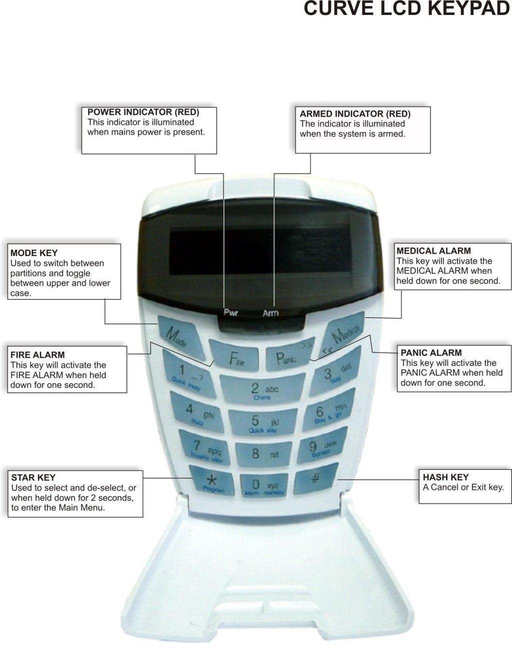
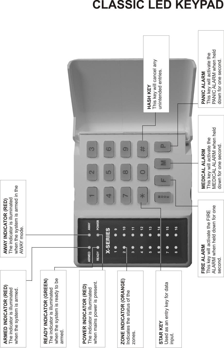
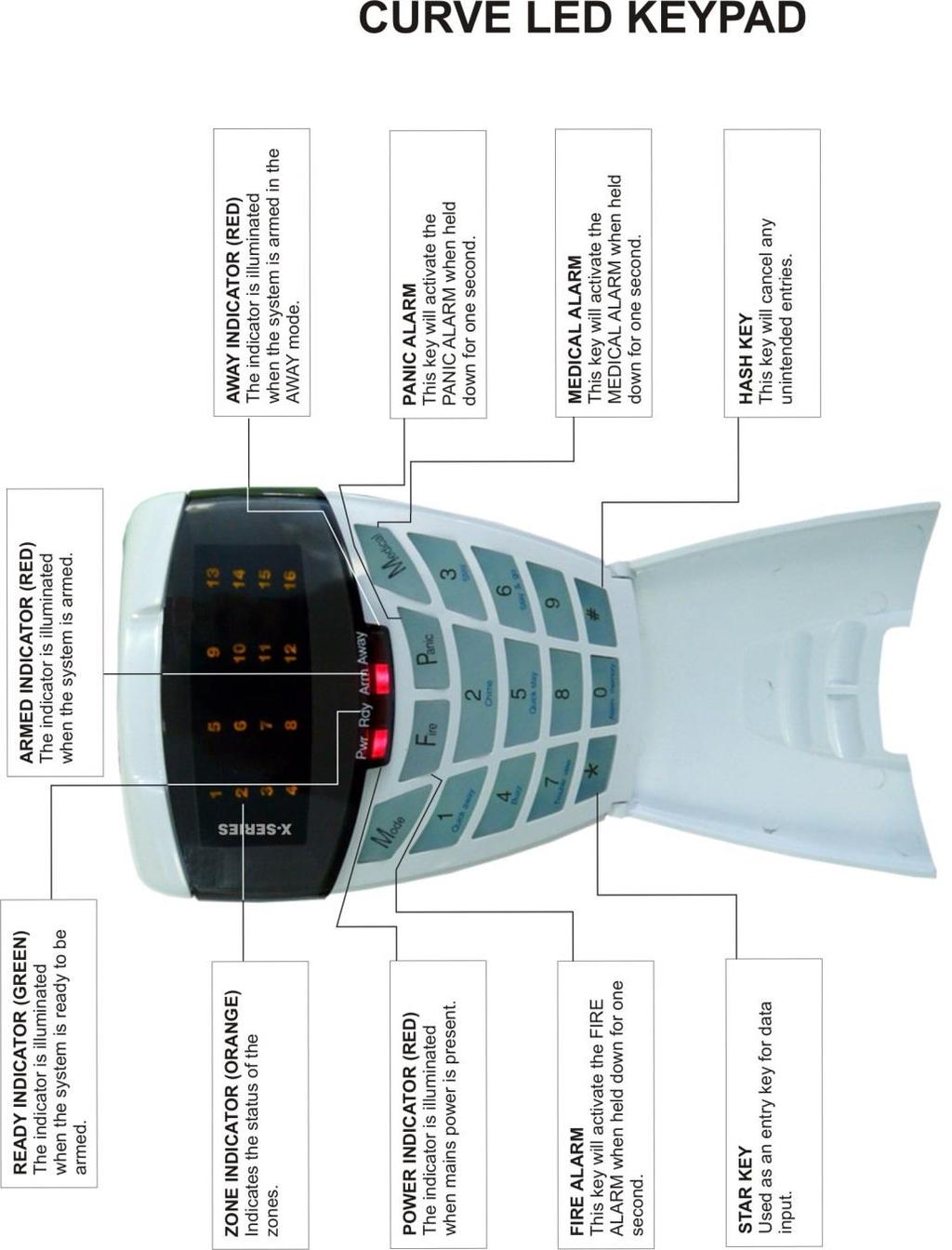
7 3. Understanding the Keypad LEDs 7
8 8
9 9
10 10
11 3.1 Viewing Data on an LED Keypad LED Status Indicators Table 1 shows the LED status indicators and the meaning of their various states. Table 1: LED Indicators ARM LED (red) Numerical Values READY LED (green) POWER LED (red) AWAY LED (red) = on = off =flashing ZONE LED (amber) DESCRIPTION System Armed in Away Mode System Armed in Stay Mode System is Ready to be Armed System Not Ready for Arming Alarm Condition (Check Alarm Memory zone details BEFORE re-arming) Mains Power is Present Mains Power has Failed Trouble Condition Zone Bypassed Zone Clear Zone Violated or Tampered Simple numerical values are represented via the zone LEDs. For instance, if zone LED 15 is on, it is representing a value of 15. This is commonly used when enabling and disabling bitmapped locations. Each zone LED directly corresponds to a number of the same value. For numbers or information that exceeds a value of 16, binary-coded decimal values are used, as explained in the following sections. Reading Binary Values Values within a data program location will be displayed by the zone LEDs in binary coded decimal format i.e. zone LEDs 1-4 indicate units (ones) and zone LEDs 5-8 indicate tens (tens), and so on. To read a binary value on the keypad, add up the values represented by each lit LED as shown in Table 2. Table 2: Values Represented by each Zone LED Zone LED Value Digit Zone LED Value Digit Zone 1 1 Zone 9 1 Zone 2 2 Zone 10 2 Units Zone 3 4 Zone 11 4 Hundreds Zone 4 8 Zone 12 8 Zone 5 1 Zone 13 1 Zone 6 2 Zone 14 2 Tens Zone 7 4 Zone 15 4 Zone 8 8 Zone 16 8 Thousands 11
12 EXAMPLE: Imagine the following zone LEDs are on: Zone 1, Zone 3 and Zone 5. Units are represented by the sum of Zone 1 and Zone 3 (i.e ). Tens of units are represented by the value of Zone 5 (i.e. 1 x ten). Therefore, the displayed value is (1+4) + (10) = 15. Values within a time program location are displayed in a similar format as per Table 3. Table 3: Binary Coded Decimal Four Digit Display Zone LED Calculation Unit Zone LED Calculation Unit 1 (x 1 = 1) 9 (x 1 = 1) 2 (x 2 = 0) 10 (x 2 = 2) m s 3 (x 4 = 4) 11 (x 4 = 4) Mm:Ss 4 (x 8 = 0) 12 (x 8 = 0) = 54:43 5 (x 1 = 1) 13 (x 1 = 1) m = LEDs 4 through 1 6 (x 2 = 0) 14 (x 2 = 0) M = LEDs 5 through 8 M S 7 (x 4 = 4) 15 (x 4 = 1) s = LEDs 12 through 9 8 (x 8 = 0) 16 (x 8 = 0) S = LEDs 16 through 13 Using an LCD keypad means that data and time information can be read directly without a need to convert. 3.2 Entering Data on an LED Keypad Data is easily entered on a keypad. Below is a list of keys and their functions. [*] This key is used as an enter key, to confirm the data that you have inputted. It is also used to scroll to the next sub-location. [#] This key is used to clear data that is incorrect. It can also be used to exit a programming option. [F] This key is used if there is a fire emergency. If programmed to do so, the fire reporting code will be sent to your monitoring company. [M] - This key is used if there is a medical emergency. If programmed to do so, the medical reporting code will be sent to your monitoring company. [P] - This key is used if there is an emergency situation that requires emergency personnel to respond. A panic alarm will be transmitted to your monitoring company. Keys marked 1 through 9, and including 0, are used to input data into the programming options. 4. The Keypad Buzzer [#] WITH any key from [0] to [6] for 1 second The keypad includes a buzzer that is used for audible signalling and verification of certain keypad functions. There are 7 possible volume settings: loud being the default setting. To program the keypad volume, use Table 4. Table 4: Keypad Buzzer Settings Key Entry Keypad Buzzer Sound Key Entry Keypad Buzzer Tone [#] [3] Loud (Default setting) [#] [6] 2kHz (High) [#] [2] Medium [#] [5] 1kHz (Medium) [#] [1] Soft [#] [4] 440Hz (Low) [#] [0] Click To change the volume (for this example to the soft setting) press the [#] and [1] keys simultaneously for 1 second (long press). After a 1-second time lapse, the keypad will respond with a beep at the new volume setting. This is a keypad specific setting, and applies to the keypad that this operation is performed on. All zones programmed as Chime or Buzz zones, will sound with a loud buzz regardless of the keypad volume set above. 12
13 5. Arming the Control Panel 5.1 Away Arm [#] [USER CODE] (Leave via Entry/Exit zone) 1. Ensure that the READY LED is on. If not, check that all protected doors and windows are closed and that all movement has ceased in areas covered by motion detectors. If necessary, close the front door. 2. Press the [#] key. 3. Enter a valid [USER CODE]. If an incorrect code is entered, the keypad buzzer will beep three times. In the event of an error press the [#] key and re-enter the code. 4. The READY LED turns off, and the ARM LED will come on and the keypad buzzer will beep repeatedly for the duration of the exit delay. Any bypassed zones will be indicated by a steady on zone LED. 5. Leave only via a designated exit route (leaving by any other route can set off the alarm). The panel will arm at the end of the exit delay. LCD Keypad [#] [USER CODE] (Leave via Entry/Exit Zone) 1. Ensure that the LCD display reads Ready to Arm alongside the partition number being armed. If not, check that all protected doors and windows are closed and that all movement has ceased in areas covered by motion detectors. If necessary, bypass any required zones and close the front door. 2. Press the [#] key. 3. Enter a valid [USER CODE]. If an incorrect code is entered, the keypad buzzer will beep three times. In the event of an error, press the [#] key and re-enter the code. 4. The ARM LED will come on and the keypad buzzer will sound for the duration of the exit delay. The LCD display will read Exit Delay alongside the partition number that is being armed. Any bypassed zones will be displayed on the LCD display as solid text. Any violated zones will be displayed on the LCD display as flashing text. To scroll through zones which have been bypassed or violated use the [PANIC] and [MED] keys. 5. Leave only via a designated exit route. The panel will away arm at the end of the exit delay, if any enter/exit zone is violated, e.g. the front door. 6. Once the panel has armed, the LCD display will read Armed alongside the partition that has been armed. 5.2 Quick Away Arm Hold down the [1] key until the beep If this function is enabled, it is possible to AWAY arm by simply holding down the [1] key until the keypad buzzer sounds and the arming process begins. If the partition is already STAY armed, this key will initialise AWAY arming. It is therefore possible to change directly from STAY arm to AWAY arm. 13
14 5.3 Stay Arm Stay arming allows the user to monitor selected perimeter zones and bypass interior zones. The user can remain on the premises with access to designated areas during the STAY ARM cycle. Any zone that may be violated accidentally should be programmed as a BUZZ ZONE. When violated, a BUZZ ZONE will cause the keypad buzzer to sound for 30 seconds before triggering the alarm and sounding the siren. Entering a valid USER CODE before the siren sounds will silence the keypad buzzer and prevent the siren from sounding. To provide greater flexibility, the panel caters for the programming of 4 different STAY PROFILES. Each STAY PROFILE contains a unique combination of STAY, BUZZ and ALARM zones that caters for a particular STAY ARM requirement. EXAMPLE: PROFILE 1 might be used when the family goes to bed in the evening. In this profile, some interior zones may be programmed as alarm zones or buzz zones, whereas PROFILE 2 is used while watching television when all interior zones would be bypassed. (See How to Select a Stay Profile, under section 13.1 page 31) How to Stay [#] [USER CODE] (Do not leave premises) 1. Select the required STAY PROFILE (See section 13.1 page 31). 2. Ensure that the READY LED is on, or the zones that are violated are stay zones. If not, check that all protected doors and windows are closed and that all movement has ceased in the areas covered by motion detectors. 3. Press the [#] key. 4. Enter a valid [USER CODE]. If an incorrect code is entered, the keypad will give an error beep. In the event of an error press the [#] key and re-enter the [USER CODE]. 5. The READY LED turns off, and the ARM LED will come on and the keypad buzzer will sound for the duration of the exit delay. 6. DO NOT violate the Entry/Exit zone (normally the front door). If the Entry/Exit zone is violated the system will arm in the AWAY mode. 7. Upon expiry of the exit delay, the READY LED will remain off. 8. Any STAY zones will be automatically bypassed (indicated by a steadily on LED). 9. Ensure that you enter only those areas that are bypassed. LCD Keypad [#] [USER CODE] (Do not leave premises) 1. Select the required STAY PROFILE. (See Section How to Select a Stay Profile page 31) 2. Ensure that the LCD display reads Ready to Arm alongside the partition number being armed. If not, check that all protected doors and windows are closed and that all movement has ceased in the areas covered by motion detectors. 3. Press the [#] key. 4. Enter a valid [USER CODE]. If an incorrect code is entered, the keypad will give an error beep. In the event of an error, press the [#] key and re-enter the [USER CODE]. 5. DO NOT violate the Entry/Exit zone (normally the front door). If the Entry/Exit zone is violated the system will arm in the AWAY mode. 6. The LCD Keypad will read Exit Delay, the ARM LED will come on and the keypad buzzer will sound for the duration of the exit delay. 7. When the panel arms, any STAY zones will be automatically bypassed. These are displayed on the LCD display as solid text. Any violated zones will be displayed on the LCD display as flashing text. To scroll through zones which have been bypassed or violated use the [PANIC] and [MED] keys. 8. Ensure that you enter only those areas that are bypassed. 14
15 5.4 Quick Stay Arm Hold down the [5] key until the beep It is possible to STAY arm by holding down the [5] key until the keypad buzzer sounds. The panel will immediately arm into the stay mode without any exit delay. All stay zones will be bypassed. Holding the button down again will cause the panel to toggle between stay profiles that have zones selected to be bypassed when stay armed. This STAY profile then becomes the active profile and the panel will STAY arm using this profile - until you elect to switch profiles again. Stay Profile Menu If the option to show the stay profile menu is enabled when pressing the [5] or [6] key to stay arm will display the stay profiles available, allowing you to choose the profile before stay arming. (Please check with your installer) (See How to Select a Stay Profile, under section 13.1 page 31) How to Stay Arm and Go Hold down the [6] key until the beep This is a single key arm function that allows the user to STAY arm and leave the premises. If a partition is already stay armed, holding down the [6] key initiates an exit delay, thus allowing the user to leave the premises without disarming. At the end of the exit delay, the partition will re-arm in the same stay profile it was armed in before the [6] key was held down. 1. Hold down the [6] key until the keypad buzzer sounds. The keypad buzzer will sound for the duration of the exit delay. Only leave via a designated exit route. 2. The READY LED will turn off and the ARM LED will come on. All stay zones will be bypassed. Holding down the [6] key until the keypad buzzer sounds also ensures an entry delay on entering the premises. LCD Keypad (Hold down the [6] key for two seconds until the keypad buzzer sounds) This is a single key arm function, which allows the user to STAY arm and leave the premises. If a partition is already stay armed, holding down the [6] key initiates an exit delay, thus allowing the user to leave the premises without disarming. At the end of the exit delay, the partition will re-arm in the same stay profile it was armed in before the [6] key was held down. 1. Make sure all zones are clear. Hold down the [6] key until the keypad buzzer sounds. The LCD display reads Exit Delay alongside the partition number being armed. Any zones that have been bypassed will be displayed on the LCD display as solid text. Any zones that are violated will be displayed on the LCD display as flashing text. Use the [PANIC] and [MED] keys to scroll through zones that have been bypassed or violated. The keypad buzzer will sound for the duration of the exit delay. Only leave via a designated exit route. 2. At the end of the exit delay, the ARM LED will come on and the display will read Stay Armed. All stay zones will be bypassed. Stay Profile Menu If the option to show the stay profile menu is enabled when pressing the [5] or [6] key to stay arm will display the stay profiles available, allowing you to choose the profile before stay arming. (Please check with your installer) 15
16 5.5 Key-switch or Remote Arming (If Fitted) 1. Ensure that the READY LED is on before leaving. 2. Leave the premises and lock the door. 3. Activate the remote or the key-switch. (A remote can be used to Away Arm.) The panel will arm in the away mode. LCD Keypad 1. Ensure that the LCD display reads Ready to Arm before leaving. 2. Leave the premises and lock the door. 3. Activate the remote or the key-switch. A remote can be used to Stay Arm or Away Arm. 4. The alarm will arm in the away mode. If a remote control is used it is advisable to either have the siren toot on arm function enabled, or to use a Remote Arm/Disarm LED Unit at the entry/exit point (P/N: ). This provides verification that the system has armed. (Speak to your installer about this feature). 5.6 Auto Arm The panel may be programmed to arm automatically at a pre-programmed time. Should the premises be occupied at the time of auto-arming, a valid user code entered during the pre-arm delay will terminate the arming sequence. The pre-arm delay is signalled by an exit beep. This can be enabled via the maintenance code, see section 19 page Disarming the Control Panel 6.1 How to Disarm with a User Code [#] [USER CODE] 1. Enter the premises through a designated entry route. Entering via any other route will cause an alarm. 2. As soon as the Entry/Exit zone is violated, the entry delay will begin. The keypad buzzer will sound for the duration of the entry period. 3. Press the [#] key and enter a valid [USER CODE]. 4. Once the system disarms, the ARM LED will turn off and the keypad buzzer will stop sounding. 5. If no valid user code has been entered prior to the expiry of the entry delay period an alarm condition will be registered. 6. If the entry period is too short, have your installer change the entry delay period. If a strobe (or flashing light) has been installed and an alarm condition is registered, the strobe will continue flashing after the siren has stopped sounding. Entering a valid user code will cancel the strobe. 6.2 How to Disarm Using a Key-switch or Remote 1. Activate the remote or key-switch. (The blue button on the IDS remote, unless otherwise programmed). 2. The system will disarm and the armed LED indicator (if installed) will turn off. If the siren toot on disarm option is enabled, the siren will provide a double toot when the panel is disarmed. 16
17 Section: 8 7. Bypassing Zones The term BYPASS is used to describe a zone that has been deactivated; i.e. violation of a bypassed zone, whilst the system is armed, is ignored and will not cause an alarm condition. Once the system is armed, it is not possible to bypass zones. All bypassed zones will be automatically cancelled each time the panel is disarmed and must be rebypassed before the next arming. To permanently bypass ones, create a stay profile and the zone. Refer to section 13 Stay Zones page Bypassing/Un-bypassing a Zone Hold down the [9] key until the beep, then enter [USER CODE] [*] [ZONE NUMBER] [*] [#] 1. Ensure that the panel is not armed (ARM LED OFF). 2. To enter bypass mode, hold down the [9] key for one second (until the keypad buzzer sounds). The AWAY LED will flash. 3. Enter [USER CODE] followed by the [*] key. The bypassed zone LEDs will be on. 4. The READY LED will come on. 5. Entering a zone number [ZONE NUMBER] followed by the [*] key will toggle the corresponding LED. For example, [2] [*] will turn LED 2 on (if it was off) and off (if it was on). The READY LED will come on. (LCD keypad press [*] again to turn N to Y) 6. Turn on the LEDs corresponding to the zones you need to bypass. The zone LEDs should now indicate only the zones that require bypassing. 7. Press the [*] key to page through to see zones If you press the [*] key again, you will view zones And press the [*] key again to see zones After each star press you can repeat steps Once satisfied with your selection, press the [#] key to exit the bypass mode. LCD Keypad Hold down [9] until the beep, then enter [USER CODE] [*] [ZONE NUMBER] [*] [*] [#] 1. Ensure the panel is not armed. 2. To enter bypass mode, hold down [9] until the beep. 3. The LCD display reads User Code + *. 4. Enter the [USER CODE] followed by the [*] key. 5. The LCD display reads Zone Number + *. 6. Enter the [ZONE NUMBER] followed by the [*] key. Alternatively, you can use the [PANIC] and [MED] keys to scroll through the zones. 7. [Y] next to the zone number indicates that the zone has been bypassed, whilst [N] indicates that the zone has not been bypassed. 8. Press the [*] key to toggle between zones being on and off. 9. Repeat steps 6-8 to bypass/un-bypass other zones. 10. Press the [#] key to exit the bypass mode. Panic zones cannot be bypassed and remember that all bypassed zones are reset at every panel disarm cycle. 17
18 8. Emergency Alarms 8.1 Fire Alarms Hold down the [F] key until the beep If the [F] key is pressed until the keypad beeps (approximately 1 second) a FIRE ALARM condition will be activated. The POWER LED stays on and the ARM LED flashes. The FIRE ALARM condition may also be triggered by a smoke detector connected to an appropriately programmed zone. The siren will sound on and off repeatedly if programmed and the FIRE REPORTING CODE will be transmitted to the monitoring company. To silence the siren enter a valid [USER CODE]. 8.2 Panic Hold down the [P] key until the beep If the [P] key is pressed until the keypad beeps (approximately 1 second) a PANIC ALARM condition will be activated. The POWER LED stays on and the ARM LED flashes. A PANIC ALARM may also be activated using any FIXED PANIC button or a REMOTE PANIC button (if installed). If the audible panic option has been selected, the siren will sound. A PANIC ALARM will be transmitted to the monitoring company. To silence the siren, enter a valid [USER CODE]. Press the [P] key only in an emergency situation that requires response by emergency personnel. 8.3 Medical Alarms Hold down the [M] key until the beep If the [M] key is pressed until the keypad beeps (approximately 1 second) a MEDICAL ALARM condition will be activated. The keypad buzzer will beep 5 times. A medical reporting code will be reported to the monitoring company. 8.4 Duress Alarms [#] [DURESS CODE] This is a special user code that should only be used in the unique situation where an intruder forces one to disarm the system under duress. When a [DURESS CODE] is entered, the control panel disarms. A Duress Alarm Code (if programmed) will be reported to the monitoring company. It is advisable to choose a Duress code that can be easily remembered by all. 18
19 9. Alarm Memory Hold down the [0] key until the beep The Alarm Memory displays any zones that were violated, tampered with, or bypassed during the last arm cycle. A flashing ARM LED notifies the user of an alarm memory condition. To view the alarm memory, disarm the panel and continue as follows: 1. Hold down the [0] key until the keypad buzzer sounds. 2. The POWER LED will turn off and the keypad buzzer will sound briefly. 3. Zone LEDs that are on show which zones were violated during the last armed period. 4. Press the [1] key followed by the [*] key to return to violated zones. 5. Press the [2] key followed by the [*] key to display zones that were bypassed. 6. Press the [3] key followed by the [*] key to display which zones were tampered with. 7. Press the [6] key followed by the [*] key to view the event log. (Only on the LCD keypad). 8. Press the [*] key to page through to see zones If you press the [*] key again, you will view zones And press the [*] key again to see zones After each star press you can repeat steps 4-7 to view the status of the zones. 10. Note that the alarm memory is erased at the beginning of each arm cycle so it should always be checked BEFORE re-arming, if necessary. 9.1 Event Log This is ONLY viewable on a LCD Keypad; it does NOT work on an LED keypad. When you view event logs, the LCD display reads as follows: HH:MM DD/MM/YYYY eeeeeeeeee p ddd Where; HH:MM = event time MM-DD- YYYY = event date eeeeeeeeee = event description p = partition event occurred in (if applicable) ddd = event data (if applicable) 1. The system time and date need to be setup correctly in order for the event log to pull the correct information. These can be setup in options 40 and When the event log menu is entered, a reference will be taken of the last event recorded. Any event prior to this reference may be viewed by scrolling back (with the [MED] key) but if the user decides to scroll forward (with the [PANIC] key) then just events up to and including this reference point will be viewable. 3. If no event is encountered then the second line will appear as No Event Pressing [6] followed by [*] after the event log viewing is already active will reset the menu to the most recent event. 5. Each event description will be followed by two numbered fields if further data is applicable to describe an event. The first number is the partition number within which the event occurred. The second number will either be the zone or user number associated with the event type. Below is an example of how an event will be displayed on the two-line IDS LCD keypad.
20 10. User Program Options The IDS X-series Alarm Panels have 128 programmable user codes. By default, user code 1 is the Master User Code that contains a pre-programmed 4-digit code of User codes may be 4 (default) or 6 digits long (with a default code of ). This is a programmable feature. Check with your installer to verify which option has been programmed Adding, Deleting and Editing User Codes Hold down the [*] key until the beep, then enter [MASTER CODE] [*] [PROGRAMMABLE OPTION] [*] The IDS X-series Panels have a friendly programmable interface that allows you to add, modify or delete user codes. See Table 5 for a summary of programmable options. The programmable interface is accessed by entering the USER PROGRAMMING MODE where it is possible to change user options. Table 5: User Programming Options Options Option 0 Option 1 Option 2 Option 3 Option 4 Option 5 Option Advanced User Options Refer to Table 6 for advanced user options. Table 6: Advanced Programming Options Options Option 11 Option 13 Option 20 Option Option 30 Option 31 Summary of Programmable Options Allows for the addition of new user codes. Allows for the editing of a selected user code. Allows for the deletion of user codes. Allows for the adding/editing of slots. Allows for the deletion of a user code using the user code slot number. Allows for the viewing of the user code slot number for a selected code. There are 128 available user code slots. Allows for the editing of the user code properties for a selected user code. Summary of Programmable Options Allows for the allocation of a selected user code to a designated partition(s). Allows for the editing of user outputs. Allows for the basic adding of remotes. Please consult the X-series Remote Receiver Manual Please consult the X-series LCD Keypad Manual Language selection 10.3 System Time and Date options Refer to Table 7 for system options. This is where you can change the time and date settings. Table 7: System Programming Options Options Option 40 Option 41 Summary of Programmable Options Allows for the editing of the time. Allows for the editing of the date. Note: If the system loses all power and then powers up when power is restored a message to set time & date will be displayed. Once set the message will be removed. 20
21 11. User Program Mode 1. Ensure that the panel is not armed. 2. Hold down the [*] key until the keypad buzzer sounds. 3. The ARM and READY LEDs will alternate flashing. 4. Enter a [MASTER USER CODE]. The factory default is Should the [MASTER USER CODE] be defaulted to 6 digits, it will be Press the [*] key. A long confirmation beep will sound.. 5. If steps 1 to 4 are performed correctly, the READY LED will flash. If an invalid code was entered, the keypad buzzer will give an error beep. (3 short beeps). If the error beep occurs, press the [#] key (this clears all previous entries) and repeat steps Select a programmable option from Table 5. EXAMPLE: To add a new user code, enter the User Program Mode by completing steps 1-4 as listed above. To access Option 0, enter a value of [0] (See Table 5) followed by the [*] key. Enter a [NEW USER CODE] followed by the [*] key. Once the user code is programmed, enter the next code followed by the [*] key. To exit user program mode press the [#] key. LCD Keypad 1. Ensure that the panel is not armed. 2. Hold down the [*] key until the keypad buzzer sounds. 3. The LCD display reads Master Code + *. The factory default is [1234]. Should the MASTER USER CODE be set to six digits it will be [123456] by default. 4. Enter the [MASTER USER CODE], followed by the [*] key. A valid entry will be confirmed by a long beep. If an invalid MASTER USER CODE was entered, the keypad buzzer will give an error beep (3 short beeps). 5. The first menu option Option Menu, Add User Code is displayed by default. 6. Select a programmable option from User Program Options. One may use the [PANIC] or [MED] keys to scroll through the menu options. 7. Confirm the entry by pressing the [*] key. A valid entry is confirmed by a long beep. An invalid entry will be signalled by means of an error beep (3 short beeps). If an error beep occurs, press the [#] key to clear all previous entries, and repeat steps 2 6. EXAMPLE: To add a new user code, enter User Program Mode by completing steps 2-4 as listed above. Menu Option 0 will be displayed on the LCD screen by default. Press the [*] key to confirm your entry. Once prompted to Enter a User Code, input a [NEW USER CODE] followed by the [*] key. Once the user code is programmed, enter the next code followed by [*]. To exit the program mode press the [#] key. Programming of these options is explained below. 12. Explanation of Programmable Options 12.1 Add a New User Code Option 0 Hold down the [*] key until the beep, then enter [MASTER CODE] [*] [0] [*] [NEW USER CODE] [*] 1. Enter the User Program Mode as per steps 1 to 4 in section Press the [0] key followed by the [*] key to select the programmable option 0 (zero). 3. The READY and ARM LEDs flash simultaneously. 4. Enter the [NEW USER CODE] followed by the [*] key. 5. The READY and ARM LEDs flash simultaneously. 6. Further codes may be added by repeating step Press the [#] key to exit the current option. 8. Press the [OPTION NUMBER] followed by the [*] key for the next option, or the [#] key again to exit user programming. 21
22 LCD Keypad 1. Enter the User Program Mode as per steps 1-4 of section. 2. The LCD display reads Option Menu, Add User Code. As this is the programmable option you require, press the [*] key. 3. The LCD display reads New Code + *. 4. Enter [NEW USER CODE] followed by the [*] key. 5. A valid entry is confirmed by a long beep. An invalid entry will be signalled by means of an error beep (3 short beeps). If an error beep occurs, press the [#] key to clear all previous entries and repeat steps Further codes can be added by repeating step 4 above. When a user code is added, it is stored in the first available user slot. 7. Press the [#] key to exit the User Program Mode. The new user code will be added to the first available slot. A slot is just a place holder number for a user code. I.e. User code 1 is in slot 1; all the way to user code 128 is in slot Edit a Selected User Code Option 1 Hold down the [*] key until the beep, then enter [MASTER CODE] [*] [1] [*] [OLD CODE] [*] [NEW CODE] [*] [#] 1. Enter the User Program Mode as per steps 1 to 4 in section Press the [1] key followed by the [*] key to select programmable option The READY and ARM LEDs flash simultaneously. 4. Enter the [OLD CODE] which is to be edited followed by the [*] key. 5. The READY and AWAY LEDs flash simultaneously, and the ARM LED will be on. 6. Enter the [NEW CODE] followed by the [*] key. 7. The READY and ARM LEDs flash simultaneously. 8. To edit other codes repeat steps Press the [#] key to exit the current option. 10. Press the [OPTION NUMBER] followed by the [*] key for the next option, or the [#] key again to exit user programming. LCD Keypad [*] [MASTER CODE] [*] [1] [*] [OLD CODE] [*] [NEW CODE] [*] [#] 1. Enter the User Program Mode as per steps 1-4 of sectionuser Program Mode. 2. The LCD display reads Option Menu, Add User Code. 3. To select menu option 1 Edit User Code, press the [1] key or alternatively use the [PANIC] or [MED] keys to scroll through the list of programmable options until you reach the option you want. 4. Press the [*] key. 5. The LCD display reads Old Code + *. 6. Enter the [USER CODE] you wish to edit followed by the [*] key. 7. The LCD display reads New Code + *. 8. Enter the [NEW CODE] followed by the [*] key. To move the cursor within the NEW CODE, use the [PANIC] or [MED] keys. 9. To edit other codes repeat steps Press the [#] key to exit the User Program Mode Delete a User Code Option 2 (Code Known) Hold down the [*] key until the beep, then enter [MASTER CODE] [*] [2] [*] [USER CODE] [*] [#] 1. Enter the User Program Mode as per steps 1 to 4 in section Press the [2] key followed by the [*] key to select programmable option The READY and ARM LEDs flash simultaneously. 4. Enter the [USER CODE] to be deleted followed by the [*] key. Deleting the code in slot one will reprogram it to
23 5. The READY and ARM LEDs flash simultaneously. 6. Further codes may be deleted by repeating step Press the [#] key to exit the current option. 8. Press the [OPTION NUMBER] followed by the [*] key for the next option, or the [#] key again to exit user programming. LCD Keypad [*] [MASTER CODE] [*] [2] [*] [USER CODE] [*] [#] 1. Enter the User Program Mode as per steps 1-4 of section User Program Mode. 2. The LCD display reads Option Menu, Add User Code. 3. To select menu option 2 Delete User Code, press the [2] key or alternatively use the [PANIC] or [MED] keys to scroll through the list of programmable options until you reach Menu Option 2. Press the [*] key. 4. The LCD display reads User Code + *. 5. Enter the [USER CODE] to be deleted followed by the [*] key. 'Deleting' the code in slot one will reprogram it to Further codes may be deleted by repeating step Press the [#] key to exit User Program Mode Add/Edit Slot Option 3 Hold down the [*] key until the beep, then enter [MASTER CODE] [*] [3] [*] [SLOT NUMBER] [*] [USER CODE] [*] [#] 1. Enter the User Program Mode as per steps 1 to 4 in section User Program Mode. 2. Press the [3] key followed by the [*] key to select Menu option The READY and ARM LEDs flash simultaneously. 4. Enter the [SLOT NUMBER] to be added/edited followed by the [*] key. 5. The READY and AWAY LEDs flash simultaneously, and the ARM LED is on. 6. Enter the [USER CODE] followed by the [*] key. 7. The READY and ARM LEDs flash simultaneously. 8. Further slots may be added/edited by repeating steps Press the [#] key to exit the current option. 10. Press the [OPTION NUMBER] followed by the [*] key for the next option, or the [#] key again to exit user programming. LCD Keypad [*] [MASTER CODE] [*] [3] [*] [SLOT NUMBER] [*] [USER CODE] [*] [#] 1. Enter the User Program Mode as per steps 1-4 of section User Program Mode. 2. The LCD display reads Option Menu, Add User Code. 3. To select menu option 3 Add/Edit Slot, press the [3] key or alternatively use the [PANIC] or [MED] keys to scroll through the list of programmable options until you reach the option you want. 4. Press the [*] key. 5. The LCD display reads Slot + *. 6. Enter the [SLOT NUMBER] to be added/edited followed by the [*] key. 7. The LCD display reads New Code + *, Slot number. 8. Enter the [USER CODE] followed by the [*] key. 9. Further slots may be added/edited by repeating steps Press the [#] key to exit User Program Mode. A slot is just a place holder number for a user code. I.e. User code 1 is in slot 1; all the way to user code 128 is in slot
24 12.5 Delete a User Code Option 4 (Slot Known) Hold down the [*] key until the beep, then enter [MASTER CODE] [*] [4] [*] [SLOT NUMBER] [*] [#] 1. Enter the User Program Mode as per steps 1 to 4 in section Press the [4] key followed by the [*] key to select Menu option The ARM and READY LEDs flash simultaneously. 4. Enter the [SLOT NUMBER] for the user code you wish to delete followed by the [*] key. You can determine the slot number of a particular code by using programmable option The READY and ARM LEDs flash simultaneously. 6. Further user codes may be deleted by repeating step Press the [#] key to exit the current option. 8. Press the [OPTION NUMBER] followed by the [*] key for the next option, or the [#] key again to exit user programming. LCD Keypad [*] [MASTER CODE] [*] [4] [*] [SLOT NUMBER] [*] [#] 1. Enter the User Program Mode as per steps 1-4 of section User Program Mode. 2. The LCD display reads Option Menu, Add User Code. 3. To select menu option 4 Delete Slot, press the [4] key, or alternatively use the [PANIC] or [MED] keys to scroll through the list of programmable options until you reach the option you want. 4. Press the [*] key. 5. The LCD display reads Slot + *. 6. Enter the [SLOT NUMBER] for the User Code you wish to delete followed by the [*] key. 7. Further User Codes may be deleted by repeating step Press the [#] key to exit User Program Mode. A slot is just a place holder number for a user code. I.e. User code 1 is in slot 1; user code 28 is in slot View a User Code Slot Number Option 5 Hold down the [*] key until the beep, then enter [MASTER CODE] [*] [5] [*] [USER CODE] [*] [#] 1. Enter the User Program Mode as per steps 1 to 4 in section User Program Mode. 2. Press the [5] key followed by the [*] key to select programmable option The READY and ARM LEDs flash simultaneously. 4. Enter the [USER CODE] followed by the [*] key. 5. The READY and ARM LEDs flash simultaneously. 6. The User Code slot number will be displayed by the Zone LEDs. (Refer to Table 2.) 7. Press the [#] key to exit the current option. 8. Press the [OPTION NUMBER] followed by the [*] key for the next option, or the [#] key again to exit user programming. LCD Keypad [*] [MASTER CODE] [*] [5] [*] [USER CODE] [*] [#] 1. Enter the User Program Mode as per steps 1-4 of section User Program Mode. 2. The LCD display reads Option Menu, Add User Code. 3. To select menu option 5, View Slot, press the [5] key or alternatively use the [PANIC] or [MED] keys to scroll through the list of programmable options until you reach Option 5. Press the [*] key. 4. The LCD display reads User Code + *. 5. Enter the [USER CODE] followed by the [*] key, the slot number is displayed on the keypad. 6. Further slot numbers may be viewed by repeating step Press the [#] key to exit the User Program Mode. A slot is just a place holder number for a user code. I.e. User code 1 is in slot 1; all the way to user code 128 is in slot
25 12.7 User Code Properties Option 10 Hold down the [*] key until the beep, then enter [MASTER CODE] [*] [1] [0] [*] [USER CODE] [*] [BITMAP] [*] [#] 1. Enter the User Program Mode as per steps 1 to 4 in section User Program Mode. 2. Press the [1] [0] keys followed by the [*] key to select programmable option The READY and ARM LEDs flash simultaneously. 4. Enter the [USER CODE] followed by the [*] key. 5. The READY and AWAY LEDs flash simultaneously, and the ARM LED will be on. 6. The properties assigned to the user code are displayed by the Zone LEDs. LED(s) that are on indicate that certain properties have been assigned to the user code. Refer to Table 8 for a list of user code properties. 7. To select a user code property, press the key which corresponds to that property followed by the [*] key. The appropriate zone LED will come on. To deselect a property, press the corresponding key followed by the [*] key and the LED will be turned off. (LCD keypad press [*] again to turn N to Y or Y to N) EXAMPLE: To enable a user code to function as a duress code press the [2] key followed by the [*] key. The zone 2 LED will come on to confirm the selection. 8. Repeat step 7 until the desired properties have been programmed. 9. Press the [#] key to exit the current option. 10. Press [OPTION NUMBER] followed by the [*] key for the next option, or the [#] key again to exit user programming. Table 8: User Code Properties Zone LED Property 1 Master User Code 2 Duress Code 3 Arm to Disarm Code [Maid s Code] 4 Arm Only Code 5 Disarm Only Code 6 Global Arm/Disarm Code 7 Programmable Output Code LCD Keypad [*] [MASTER CODE] [*] [1] [0] [*] [USER CODE] [*] [PROPERTY NUMBER] [*] [*] [#] 1. Enter the User Program Mode as per steps 1-4 of section Error! Reference source not found.. 2. The LCD display reads Option Menu, Add User Code. 3. To select menu option 10 Code Properties, press the [1] [0] keys or alternatively use the [PANIC] or [MED] keys to scroll through the list of programmable options until you reach the option you want. 4. Press the [*] key. 5. The LCD display reads User Code + *. 6. Enter the [USER CODE] followed by the [*] key. 7. Enter the [PROPERTY NUMBER] followed by the [*] key, or use the [PANIC] or [MED] keys to scroll through the User Options that can be assigned to a user. 8. Pressing the [*] key toggles between [Y] and [N] for the selected user option. 9. Press the [#] key twice to exit User Program Mode. EXAMPLE: To enable a User Code to function as a duress code, when prompted for the option press the [2] key followed by the [*] key. 25
26 Master User When assigned to a user, this property allows the user to act as a Master User. Master User Code has full access to programming all the user options. Duress Code This is a special 4 (default) or 6-digit user code (check the code length with your installer) and should only be used in the unique situation where an intruder forces one to disarm the system "under duress". When the [DURESS CODE] is entered, the control panel disarms normally - however a DURESS REPORTING CODE is transmitted to the monitoring company to inform them that you have been forced to disarm the control panel by an intruder. It is advisable to choose a code that can easily be remembered by all family (or staff) members. Arm to Disarm Code [Maid's Code] This property may be used to limit access to the premises. A maid's code will only disarm the system if the same code was used for arming. If armed with a code other than this code, the system will view an attempt to disarm using a maid's code as an invalid entry. Any valid user code will disarm the system if it has been armed with a maid s code. Arm Only Code This code will arm the partitions assigned to the user depending on their status. If all partitions are disarmed, entering an arm code will arm all of the assigned partitions. In a case where some partitions are armed and others disarmed, entering this group code at the keypad of the disarmed partition will arm the disarmed partitions only. Disarm Only Code This code will disarm the partitions assigned to the user depending on their status. If all partitions are armed, entering a group code will disarm all of the assigned partitions. In a case where some partitions are disarmed and others armed, entering this group code at the keypad of the armed partition will disarm the armed partitions only. Global Arm/ Disarm Code When there is more than one partition, and all are disarmed, entering a global code will arm all partitions that are ready to arm. If all partitions are armed then entering a global code will disarm all partitions. Where some partitions are armed and other partitions are disarmed then entering a global code at the keypad of an armed partition will disarm all partitions. Similarly, entering a global code at the keypad of a disarmed partition will arm all partitions, if they are ready to arm. A remote transmitter programmed with a global code will arm all disarmed partitions when the arm/disarm button is pressed, if they are ready to arm. A partition that is not ready to arm, for instance one with a zone violation, will NOT arm with the global arm/disarm code. Programmable Output Code This user property enables the use of various programmable outputs to perform home automation actions, such as turning on lights, switches, motors, etc. Any event which is able to trigger a programmable output can be assigned to an output number from 1 to 41. Assigning an event to outputs 1 to 5 will use the panel s onboard outputs 1 to 5. Assigning an event to outputs 6 to17 will use an output on a zone expander, are reserved, and will use an output on a keypad. Refer to section 12.9 for details on using programmable outputs. 26
27 12.8 Assign a User Code to Partitions Option 11 (Advanced) Hold down the [*] key until the beep, then enter [MASTER CODE] [*] [1] [1] [*] [USER CODE] [*] [PARTITION No] [*] [#] 1. Enter the User Program Mode as per steps 1 to 4 in section User Program Mode 2. Press the [1] [1] keys followed by the [*] key to select programmable option The READY and ARM LEDs flash simultaneously. 4. Enter the [USER CODE] followed by the [*] key. 5. The READY and AWAY LEDs flash simultaneously, and the ARM LED will be on. 6. The partitions to which the user code is assigned are displayed by the zone LEDs. If zone LED 1 is on, the user code can arm or disarm partition 1. If zone LED 2 is on, the user code can arm or disarm partition 2. It is possible to program codes to arm/disarm more than one partition. 8. To select which partitions the user code may arm or disarm, toggle zone LEDs by entering the [PARTITION No] followed by the [*] key. (LCD keypad press [*] again to turn N to Y or Y to N) 7. The READY and AWAY LEDs flash simultaneously, and the ARM LED is on. To allocate a user to all partitions press the [0] key followed by the [*] key, when inputting the data for the partition number. 8. Repeat step 7 until the user code has been assigned to the correct partition(s). 9. Press the [#] key to exit the current option. 10. Press the [OPTION NUMBER] followed by the [*] key for the next option, or the [#] key again to exit user programming. LCD Keypad [*] [MASTER CODE] [*] [1] [1] [*] [USER CODE] [*] [PARTITION NUMBER] [*] [*] [#] 1. Enter the User Program Mode as per steps 1-4 of section User Program Mode 2. The LCD display reads Option Menu, Add User Code. 3. To select menu option 11 User ->Partitions, press the [1] [1] keys or alternatively use the [PANIC] or [MED] keys to scroll through the list of programmable options until you reach the option you want. 4. Press the [*] key. 5. The LCD display reads User Code + *. 6. Enter the [USER CODE] followed by the [*] key. 7. The partitions to which the [USER CODE] is assigned are indicated by options 1-8. If the user is assigned to partition 1, there will be a YES next to option 1 and the user can thus arm and disarm partition 1. If the user is assigned to partition 4, there will be a YES next to option 4. It is possible to program codes to arm/disarm any combination of the available partitions. 8. Enter the [PARTITION NUMBER] followed by the [*] key. One may also use the [PANIC] and [MED] keys to scroll through the partitions. 9. Press the [*] key to toggle between YES and NO. 10. Repeat steps 8-9 until the User Code has been assigned to the correct partition(s). Press the [#] key twice to exit the User Program Mode When a new user is added, they are assigned to partition 1 by default. To change this, or to add them to other partitions, requires that you program this option. If you do not add a user to a partition, they will not be able to arm/disarm it. 27
Contents. 4. Disarming the Control Panel How to Disarm with a User Code How to Disarm using a Key-Switch or Remote...
 Contents 1. Introduction to the Watchguard WGAP864 LCD Digital Keypad... 6 2. Viewing Violated Zones... 6 3. Arming the Control Panel... 7 3.1 Away Arming... 7 3.1.1 How to Away Arm... 7 3.1.2 Quick Away
2 IDS LCD Keypad User Manual C Issued March 2009
 2 3 4 Contents 1. Introduction to the IDS LCD Digital Keypad...8 2. Arming the Control Panel...8 2.1 Away Arming...8 2.1.1 How to Away Arm...8 2.1.2 Quick Away Arm Shortcut Key...8 2.2 Stay Arming...9
IDS. Users Guide to Keypad Functions S E C U R I T Y MANUAL NO D ISSUED NOVEMBER 2002 VERSION 2.
 INHEP DIGITAL IDS S E C U R I T Y Users Guide to Keypad Functions MANUAL NO. 700-146-01D ISSUED NOVEMBER 2002 VERSION 2.17 Summary of Operation A rm/ disarm [#] + [USER CODE] Quick Quick Quick Away Arm
Important Notice. Customer Information. 2 WisDom User Manual
 User Manual Important Notice This manual is delivered subject to the following conditions and restrictions: This manual contains proprietary information belonging to RISCO Group. The information is supplied
IDS1200 INSTALLER MANUAL. Summary of Operation 2 IDS1200 INSTALLER MANUAL - NO B ISSUED AUGUST 2002 VER 1.18
 IDS12 INSTALLER MANUAL Summary of Operation A rm/ disarm [#] + [USER CODE] Quick Away Arm Quick Stay Arm Quick Stay Arm & Go H old down [ 1] for 1 second H old down [ 5] for 1 second H old down [ 6] for
Created by: Alarm System Store Quick Start Guide. for Interlogix NetworX NX4, NX6 & NX8
 Quick Start Guide for Interlogix NetworX NX4, NX6 & NX8 Programming Code = 9713 Master User Code=1234 Program Mode= *8 + 9713 To exit programming hit the Exit key until you reach the home screen If this
INT-KSG Keypad Quick user s guide
 INT-KSG Keypad Quick user s guide Firmware version 1.02 int-ksg_u_en 01/13 SATEL sp. z o.o. ul. Schuberta 79 80-172 Gdańsk POLAND tel. + 48 58 320 94 00 info@satel.pl www.satel.eu WARNINGS Please read
VoiceNav User Manual
 r VoiceNav User Manual 1 Table of contents Introduction 2 Drawing 3 Glossary of terms 4 Glossary of terms continued 5 Legend 5 Warranty 5 Indicators, icons and lights 6 Away arming 7 Stay arming 8 Disarming
RANGER 9000E DOWNLOADABLE CONTROL COMMUNICATOR INSTALLATION MANUAL
 RANGER 9000E DOWNLOADABLE CONTROL COMMUNICATOR INSTALLATION MANUAL TABLE OF CONTENTS GENERAL DESCRIPTION... 2 STANDARD AND OPTIONAL PARTS LIST... 2 FEATURE DEFINITIONS... 3 TERMINAL DRAWING AND SPECIAL
DSC programming for the Alexor and Impassa
 DSC programming for the Alexor and Impassa THERE IS NO REASON TO BE IN ANY SECTION OF YOUR SYSTEM UNLESS IT IS ON THIS QUICK START GUIDE. If you do not see it here, please question if you should be doing
D1260/D1260B. Owner's Manual. Keypad
 D1260/D1260B EN Owner's Manual Keypad D1260/D1260B Owner's Manual This system includes a telephone line seizure feature. The system may be programmed to communicate with a central monitoring station to
DAS 250L CONTROL COMMUNICATOR INSTALLATION MANUAL
 DAS 250L CONTROL COMMUNICATOR INSTALLATION MANUAL TABLE OF CONTENTS 1. GENERAL DESCRIPTION... P.2 2. STANDARD AND OPTIONAL PARTS LIST..... P.2 3. FEATURE DEFINITIONS... P.3 4. TERMINAL DRAWING AND SPECIAL
INT-KSG Keypad Quick user s guide
 INT-KSG Keypad Quick user s guide Firmware version 1.00 int-ksg_u_en 08/10 SATEL sp. z o.o. ul. Schuberta 79 80-172 Gdańsk POLAND tel. + 48 58 320 94 00 info@satel.pl www.satel.eu WARNINGS Please read
Series. NX-8-EUR Control Panel. Installation manual
 g GE Security NetworX TM Series NX-8-EUR Control Panel Installation manual NX-8-EUR Installation manual Page 2 23/12/04 CONTENTS CONTENTS...3 GENERAL INFORMATION...5 ORDERING INFORMATION...5 FEATURE DEFINITIONS...6
1HWZRU;1;( Table of Contents. General Description...2. Ordering Information...2. Feature Definitions...3. Programming the LED Keypads...
 HWZRU;;( Control/Communicator Installation Manual Table of Contents General Description... Ordering Information... Feature Definitions... Programming the LED Keypads... Programming the NX-E...9 Types of
Property of Monitronics Inc
 Enter Program 1. Master Code + 8 + 0 + 0 (Display should show 20) or Power down then back up and press * and # within 1 minute (If exiting programming you can re-enter within 1 minute by pressing * and
Solution 16 plus. User Guide Security System
 Solution 16 plus EN Security System Copyright Notice Unless otherwise indicated, this publication is the copyright of Bosch Security Systems Pty Ltd ( Bosch ). All rights are reserved.you may download
LCD User Station User Manual
 LCD User Station User Manual PUBLICATION INFORMATION 504A R Final Release CONTENTS 1.0 INTRODUCTION... 4 1.1 Legend... 2.2 Terminology... 2.0 OPERATION... 8 2.1 Indicator Lights... 2.2 Visual Display...
Table of Contents. Phone number configuration...15 Alarm Phone numbers, 1, 2 & Divert phone numbers 1, 2 &
 Table of Contents Introduction... 4 Warning... 5 Warranty... 5 Glossary of terms... 6 Legend... 7 Feature & Benefits... 8 1. Phone Line connection... 8 Phone Line connection, and network connection...9
PROGRAMMING HELP GUIDE
 DIGIPLEX EVO48-192 PROGRAMMING HELP GUIDE Entering Programming Mode 1) Press and hold the [0] key 2) Enter your [Installer Code] (default-000000) 3) Enter 4-digit [section] you wish to program 4) Enter
QUICK CONSUMER REFERENCE GUIDE
 QUICK CONSUMER REFERENCE GUIDE YOUR SYSTEM: ADT PM33 Commercial System Starting to use the Alarm Panel and Keypad PM33 Control Panel KP-250 PG2 Keypad Keyfob Setting Your System Step 1 When leaving your
Property of Monitronics Inc
 Enter Program (Locations 034 to 410) 1. Press Program Button on main panel 2. At keypad press 9 + Program Code (9 8 7 6 5) or 1. Power down with black switch on bottom left of panel 2. Power up while holding
SECURITY MODULE CG3 User Manual
 SECURITY MODULE CG3 User Manual Security system can be managed with Paradox K636, K10 LED, K32 LED and Protegus SK130 LED Control by the keypad Paradox 1. Full arming the security system (when the security
SigNET 200/300 User Guide
 SigNET 200/300 User Guide Warning: While this system is an advanced design integrated security system, it does not offer guaranteed protection against burglary, fire or other emergency. Any alarm system,
Safecom Solution-16 Quick Reference Guide ISSUE 1.10
 Safecom Solution-16 Quick Reference Guide ISSUE 1.10 2 Solution-16 Safecom Quick Reference Guide Safecom Solution-16 Quick Reference Guide Copyright 1998 by, SYDNEY, AUSTRALIA Document Part Number MA8016Q
DAS LCD ALPHA NUMERIC CODEPAD
 DAS LCD ALPHA NUMERIC CODEPAD Table of Contents 1. LCD Codepad Diagram... 2 2. Introduction... 3 3. Understanding Your LCD Codepad... 4-7 4. Changing User Codes... 8-9 5. Special Function Keys..... 10
Solution 144 Security Systems
 Security Systems EN Security System Copyright Notice Unless otherwise indicated, this publication is the copyright of Bosch Security Systems Pty Ltd ( Bosch ). All rights are reserved.you may download
NX-148 LCD KEYPAD INSTALLATION MANUAL
 NX-148 LCD KEYPAD INSTALLATION MANUAL Table of Contents Entering the Program Mode... 2 Selecting the Module to Program... 2 Programming a Location... 2 NX-148 Library... 3 Loading Factory Defaults... 3
VISTA 12a / 48a TECHNICAL TRAINING. The Best in Security plus Everyday Convenience & Control
 VISTA 12a / 48a TECHNICAL TRAINING The Best in Security plus Everyday Convenience & Control Version #.007 7th June 2005 VISTA 12a / 48a Training Guide Index 1. Vista Family Features....... p. 3 2. Wiring
Control Panel ICP-SOL2-P/ICP-SOL3-P. en Quick Reference Guide
 Control Panel ICP-SOL2-P/ICP-SOL3-P en Quick Reference Guide Control Panel Table of Contents en 3 Table of contents 1 Introduction 6 2 Programming 7 2.1 ICON LCD Codepad Programming 7 2.2 TEXT LCD Codepad
Integriti User Manual. Elite / EliteX LCD Terminal Keypads
 Integriti User Manual Elite / EliteX LCD Terminal Keypads INNER RANGE recommends that all INTEGRITI systems are installed & maintained by FACTORY CERTIFIED TECHNICIANS. For a list of Accredited Dealers
_A_en_LED63VG VOICE GUIDE KEYPAD LED63VG
 18020502_A_en_LED6VG VOICE GUIDE KEYPAD LED6VG Disclaimer While every effort has been made to ensure that the information in this manual is accurate and complete, no liability can be accepted for any errors
EUROPLEX TECHNOLOGIES. WARNING. Copyright. Disclaimer
 EUROPLEX TECHNOLOGIES. Company Web Site address: www.europlex.com Europlex Technologies [Ireland] Ltd. Clonshaugh Industrial Estate, Clonshaugh, Dublin 17, Ireland. Tel: +353-1 - 8485111 Fax: +353-1 -
SILENCING AN ALARM. When the alarm bell or siren is sounding, enter your user code or present your keyfob to your keypad.
 S Y S T E M U S E R G U I D E SILENCING AN ALARM When the alarm bell or siren is sounding, enter your user code or present your keyfob to your keypad. IS THIS A FALSE ALARM? YES NO displays. REAL ALARM
AMAX panel. AMAX panel 2100 AMAX panel 3000 AMAX panel 3000 BE AMAX panel en Operation Manual
 AMAX panel AMAX panel 2100 AMAX panel 3000 AMAX panel 3000 BE AMAX panel 4000 en Operation Manual AMAX panel Table of Contents en 3 Table of contents 1 Safety 5 2 Short information 6 2.1 Introduction
First Alert FA160C/162C Installer Notes M. Leuck
 First Alert FA160C/162C Installer Notes M. Leuck 1. Programming can only be done by 6139 Alpha keypads, standard 6128 keypad cannot be used to program zones 2. Enter programming: Master Code + 8 + 0 +
Clipsal HomeMinder Home Automation System
 Clipsal HomeMinder Home Automation System Part A Release 1.0.0 4 June 2000 Copyright 2000 Clipsal Integrated Systems Preface Congratulations on your purchase of HomeMinder. You now own a powerful and
High Security and Access System EVO48 V2.1 EVO192 V2.1
 High Security and Access System EVO48 V2.1 EVO192 V2.1 Programming Guide Includes LCD Keypad Programming We hope this product performs to your complete satisfaction. Should you have any questions or comments,
USERS MANUAL.
 USERS MANUAL Ness Corporation Pty Ltd ABN 28 069 984 372 Private Bag 23 Seven Hills NSW 1730 Australia Ph +61 2 8825 9222 Fax +61 2 9838 8508 Email: ness@ness.com.au SYDNEY Ph 02 8825 9222 Fax 02 9674
Protege WX End User Guide
 PRT-WX-DIN Protege WX End User Guide The specifications and descriptions of products and services contained in this document were correct at the time of printing. Integrated Control Technology Limited
I-NX8V2-IM Rev F Dec NetworX Series NX-8V2 Control Panel Installation and Setup
 I-NXV-IM Rev F Dec 00 NetworX Series NX-V Control Panel Installation and Setup Copyright Disclaimer Trademarks and patents Copyright 00, GE Security Inc. All rights reserved. This document may not be copied
LCD62. Keypad. User Manual
 LCD62 Keypad User Manual Disclaimer: While every effort has been made to ensure that the information in this manual is accurate and complete, no liability can be accepted for any errors or omissions The
Modules Programming Guide. paradox.com
 Keypad Modules Annunciator Module Motion Detector Modules Zone Expansion Modules Access Control Module Voice Assisted Modules Accessory Modules Integration Module Internet Module Modules Programming Guide
Security System. Owner s Manual
 Security System Owner s Manual What You Need to Know Before using this manual, you should become familiar with the Security System User s Guide. The User s Guide provides step by step instructions for
MCM Electronics MCM Electronics MCM Electronics. The Icon Series. Installation and Programming Information. Icon 8 Version 5.0
 MCM Electronics MCM Electronics MCM Electronics The Icon Series Installation and Programming Information Icon 8 Version 5.0 TABLE OF CONTENTS 1. 2. 3. Panel Hardware Page 2 Physical Layout. Inputs. Outputs.
Installer Notes 4110DL/XM, Vista 10, Vista-20, Via-30PSE
 Installer Notes 4110DL/XM, Vista 10, Vista-20, Via-30PSE 1. Programming can only be done with a 6139 Alpha Keypad on Vista-10/20/30PSE models. 2. When entering programming for the first time during Installations
User Manual RINS1209-5
 User Manual 2x 2x RINS1209-5 The EURO mini Keypad Contents Introduction 1-5 Using EURO mini with PIN Codes 5-9 Intelligent Setting 10-11 When Problems Arise 12 Setting Individual Areas 13-14 Chime Facility
Operating & ProgrammingGuide
 LCD Keypad Operating & ProgrammingGuide Arrowhead Alarm Products Ltd VERSION 2.03 Proudly Designed and Manufactured in New Zealand 1 CONTENTS Page No. INTRODUCTION 3 Introduction to the LCD Keypad 3 KEYPAD
Control Panels D9412GV4/D7412GV4. en Owner's Manual
 Control Panels D9412GV4/D7412GV4 en Owner's Manual Control Panels Table of Contents en 3 Table of contents 1 Introduction 8 1.1 About documentation 9 2 Keypads overview 11 2.1 Identify your keypad style
Quick Start: 2. Connect AC power first and then the battery. 3. Configure the keypad (see page 44).
.") R R R HARDWIRE WIRELESS Quick Start:. Refer to the wiring diagram, connect siren, aux. power, pgm. output, remote bus, earth ground, zone and telephone wiring. NOTE: See Installation Instructions (WI99)..
R R R HARDWIRE WIRELESS Quick Start:. Refer to the wiring diagram, connect siren, aux. power, pgm. output, remote bus, earth ground, zone and telephone wiring. NOTE: See Installation Instructions (WI99)..
Property of Monitronics Inc
 Enter Program Master Code + 8 + 0 + 0 (Display should show 20) or Power down then back up and press * and # within 1 minute (If exiting programming you can re-enter within 1 minute by pressing * and #)
Security System User Guide
 Security System User Guide Setting the System: 1. Go to the keypad and key in your access code. (Alternatively, if you have a proximity tag, present your tag to the keypad.) Either - Full Set: 2. Press
4140XMPT2 PROGRAMMING FORM
 414XMPT2 PROGRAMMING FORM Some fields are programmed for each partition (shown as shaded fields). See the PARTITION-SPECIFIC section for programming these fields. Standard default (*97) values are shown
Installation Instructions
 NX-148E-RF LCD Touchpad w/receiver 466-2198 Rev. B May 2005 Product summary The NX-148E-RF Touchpad w/receiver combines touchpad and receiver capabilities into a single device for use with NetworX NX-4,
SUPERPLEX. User s Manual. High performance, simplified wireless home security controller. Products that work. Software Release: V2.
 SUPERPLEX User s Manual Products that work Software Release: V2.5 KE-MOBILEHQ-12- High performance, simplified wireless home security controller Thank you for purchasing this Kingdom Electronics product.
DAYLIGHT SAVINGS TIME START/END MONTH [ 0 ]0 = Disabled; 1 = Enabled. 1 Start End
![DAYLIGHT SAVINGS TIME START/END MONTH [ 0 ]0 = Disabled; 1 = Enabled. 1 Start End](/thumbs/72/66709046.jpg "DAYLIGHT SAVINGS TIME START/END MONTH [ 0 ]0 = Disabled; 1 = Enabled. 1 Start End") RcvrAcct#: Test Date: May, ::PM SYSTEM ENTRY DELAY# [ ] = None, = secs, = secs, = secs, = secs, = secs, = mins [UL installations: The Entry Delay must be set for a maximum of seconds] ENTRY DELAY# [ ]
RcvrAcct#: Test Date: May, ::PM SYSTEM ENTRY DELAY# [ ] = None, = secs, = secs, = secs, = secs, = secs, = mins [UL installations: The Entry Delay must be set for a maximum of seconds] ENTRY DELAY# [ ]
Control Panels B9512G/B8512G/B6512/B5512/B4512/B3512. en Owner's Manual
 Control Panels B9512G/B8512G/B6512/B5512/B4512/B3512 en Owner's Manual Control Panels Table of Contents en 3 Table of contents 1 Introduction 8 1.1 About documentation 9 2 Keypads overview 11 2.1 Identify
THE OPERATOR INTRODUCTION 2 ACCESSING YOUR SYSTEM 2 FUNCTIONS OF THE "OPERATOR" 3 PROGRAMMING/CHANGING ACCESS CODES 12 ACTIVATING EMERGENCY ALARMS 13
 THE OPERATOR INTRODUCTION 2 ACCESSING YOUR SYSTEM 2 FUNCTIONS OF THE "OPERATOR" 3 SECTION I. CHECKING SYSTEM STATUS 3 SECTION II. USING THE MENU 4 SECTION III. ARMING YOUR SECURITY SYSTEM 5 SECTION IV.
CA62 User s Manual - Operation with LED62 Keypad and PR62 Proximity Cards Reader. English
 English CA62 User s Manual - Operation with LED62 Keypad and PR62 Proximity Cards Reader Contents LED62 General Description 4 General Description 4 LED Indication 5 Keypad Sounder 7 Buttons 7 LED62 Keypad
INT-TSI Brief User Manual
 int-tsi_u_en 03/15 Keypad INT-TSI Brief User Manual SATEL sp. z o.o. ul. Budowlanych 66 80-298 Gdańsk POLAND tel. 58 320 94 00 info@satel.pl www.satel.eu Firmware version 1.04 WARNINGS Please read this
VISTA-128BP/VISTA-250BP Programming Form
 VISTA-128BP/VISTA-250BP Programming Form Some fields are programmed for each partition (shown as shaded fields). If you are programming a multiple-partition system, see the Partition-Specific Fields section
2 4PI175 issue 1_6/01. How to unset system in alarm. Programs 1, 2 and 3. Access codes. How to operate Personal Attack
 Access codes Contents Unset system indications - - - - - - - - - - - System indication - - - - - - - - - - - - Access codes - - - - - - - - - - - - - - - - How to operate Personal - - - - - - How to unset
KarizmaPlus Intruder alarm system Operating instructions
 KarizmaPlus Intruder alarm system Operating instructions Introduction The purpose of this user guide is to describe how to operate Karizma plus system. Some of the features described in this guide may
Ademco Vista-20SE/First Alert FA-162C Program Sheet
 Enter Program 1. 4112 + 8 + 0 + 0 (Display should show 20) or Power down then back up and press * and # within 1 minute (If exiting programming you can re-enter within 1 minute by pressing * and #) Exit
Installation Quick Start Guide
 Installation Quick Start Guide For detailed information please refer to the full Agility 3 Installer Manual provided on our website: www.riscogroup.com Table of Contents 1. INSTALL THE MAIN UNIT... 3 2.
SL2000E. Status Output. Electronic Code Lock. Features. Input. Exit Button Input. Introduction. Door Contact Input. Functional Description.
 SL2000E Electronic Code Lock Features Door Relay output Status transistor output Aux transistor output Door Contact input Exit Button input INSTALLER code for programming MASTER code for arming/disarming
USER GUIDE. for Android Version 1. alula.net ALULA 1
 USER GUIDE for Android Version 1 alula.net 1-888-88-ALULA 1 1. GETTING STARTED 3 2. DOWNLOAD THE ALULA APP 3 3. SIGN IN 3 4. LOCATIONS 4 5. MAIN DASHBOARD SCREEN 5 5.1. Application Menu 5 5.2. Feature
SIGMA "APOLLO" APOLLO User Manual Page 1
 SIGMA "APOLLO" APOLLO" control panel manufactured, by SIGMA SECURITY is a modern, state of the art, security system which can cover the security needs of a household, or an office. It has been designed
ELECTRONIC ENGINEERING LTD. OLED Keypad. User s Guide. P/N: Doc Rev-A SW Ver /08/10
 ELECTRONIC ENGINEERING LTD. OLED Keypad User s Guide P/N: 7103670 Doc Rev-A SW Ver-0.65 05/08/10 Crow Limited Warranty Crow warrants this product to be free from defects in materials and workmanship under
Wireless Alarm System User Guide
 Wireless Alarm System User Guide Alarm Panel Time 10:09 c RINS1902 Document SAP: 102015108-03 Contents ProControl+ 4 Setting Devices 5 The Wireless Panel Keypad 5 Wireless Keyfobs 5 Locking the Keyfob
REMOTE KEYPAD with NFC Tag (KPT-32N, KPT-32N-F1)
") REMOTE KEYPAD with NFC Tag (KPT-32N, KPT-32N-F1) April 01st, 2016 Identifying the Parts 1. Siren 2. Orange LED: Home Arm Key 3. Red LED: Away Arm Key 4. Panic Alarm (if enabled) - Press both 1 and 3 to
REMOTE KEYPAD with NFC Tag (KPT-32N, KPT-32N-F1) April 01st, 2016 Identifying the Parts 1. Siren 2. Orange LED: Home Arm Key 3. Red LED: Away Arm Key 4. Panic Alarm (if enabled) - Press both 1 and 3 to
ACTsmart2 Product Range Operating and Installation Instructions
 ACTsmart2 Product Range Operating and Installation Instructions 18-00045 Contents ORDERING INFORMATION......4 INSTALLATION NOTES......5 IMPORTANT......5 PRODUCT SPECIFICATION......5 30 SECOND PROGRAMMING
VISTA-20SEa. 3-Partition Security System. Programming Form. V20SEaPRV1 9/98
 VISTA-20SEa 3-Partition Security System New style cover to be used Programming Form V20SEaPRV1 9/98 Local programming requires the use of a 2-line Alpha keypad connected to Partition 1 keypad terminals
NX-595E User Manual P/N REV C ISS 02JUL14. Downloaded from manuals search engine
 NX-595E User Manual P/N 230243 REV C ISS 02JUL14 Copyright Trademarks and patents Manufacturer Compliance EU directives Contact information Customer support 2014 UTC Fire & Security Americas Corporation,
*00 INSTALLER CODE Enter 4 digits, 0-9 [4140] *28 POWER UP IN PREVIOUS STATE [1=yes] 0=no; "1" for UL.
![*00 INSTALLER CODE Enter 4 digits, 0-9 [4140] *28 POWER UP IN PREVIOUS STATE [1=yes] 0=no; 1 for UL.](/thumbs/79/80354276.jpg "*00 INSTALLER CODE Enter 4 digits, 0-9 [4140] *28 POWER UP IN PREVIOUS STATE [1=yes] 0=no; 1 for UL.") 4140XMPT2 PROGRAMMING FORM Some fields are programmed for each partition (shown as shaded fields). See the PARTITION-SPECIFIC section for programming these fields. Standard default (*97) values are shown
4140XMPT2 PROGRAMMING FORM Some fields are programmed for each partition (shown as shaded fields). See the PARTITION-SPECIFIC section for programming these fields. Standard default (*97) values are shown
eurösec CPX Control Panel User Instructions
 eurösec CPX Control Panel User Instructions eurösec CPX User Manual Contents User Information... 2 Introduction... 3 User Code Types... 3 Setting The System... 4 Setting & Unsetting via Keyswitch... 4
Virtual Keypad App Help Last update: 2017/02/02
 Virtual Keypad App Help 16461 Last update: 2017/02/02 Table of Contents Virtual Keypad App Help Center... 1 Managing Your App Account... 2 Using Your App... 3 System in Alarm... 4 Contacting Your Security
USER GUIDE. for ios Version 1. alula.net ALULA 1
 USER GUIDE for ios Version 1 alula.net 1-888-88-ALULA 1 1. GETTING STARTED 3 2. DOWNLOAD THE ALULA APP 3 3. SIGN IN 3 4. 4. LOCATIONS 4 5. MAIN DASHBOARD SCREEN 5 5.1. Application Menu 5 5.3. Feature Menus
Emergency Dialer DIAL-ALERT MODEL: AD-105.
 www.skylinkhome.com Emergency Dialer TM DIAL-ALERT MODEL: AD-105 If you would like to order Skylink s products or have difficulty getting them to work or download information and user manual, please :
Property of Monitronics Inc
 Enter Program 1. 4112 + 8 + 0 + 0 (Display should show 20) or Power down then back up and press * and # within 1 minute (If exiting programming you can re-enter within 1 minute by pressing * and #) Exit
Karizma PlusTM. Intruder alarm system Operating instructions. Introduction
 Karizma PlusTM Intruder alarm system Operating instructions Introduction The purpose of this user guide is to describe how to operate Karizma plus system. Some of the features described in this guide may
Digiplex EVO High Security and Access System What s New EVO192 V2.7
 Digiplex EVO High Security and Access System What s New EVO192 V2.7 Overview New zone programming and additional zone/system/anti-mask options EN 50131 compliancy Now supports automatic label broadcast
CP150B Vandal & Weather Resistant Keypad Security Systems
 Vandal & Weather Resistant Keypad Security Systems EN Security System CP150B - Vandal & Weather Resistant Keypad The CP150B keypad provides alarm and or access control functionality when used on selected
ATS1190 Smart Card Reader Programming Manual
 ATS1190 Smart Card Reader Programming Manual Version 2.0 Aritech and Tecom are Interlogix Companies 2001 Interlogix B.V.. All rights reserved. Interlogix B.V. grant the right to reprint this manual for
Developer s Guide. PC54O1 Serial Interface Module Version 1.0
 Developer s Guide PC54O1 Serial Interface Module Version 1.0 IMPORTANT This manual contains information on limitations regarding product use and function and information on the limitations as to liability
Modules Programming Guide
 Modules Programming Guide Programming Methods The modules can be programmed using the following methods: 1) Through the WinLoad Security Management Software. The modules can be programmed at 19,200 baud
SUPERPLEX 2. User s Manual. High performance, simplified wireless home security controller. Products that work. Software Release: V2.
 SUPERPLEX 2 User s Manual Products that work Software Release: V2.0 KE-MOBILEHQ-12- High performance, simplified wireless home security controller Thank you for purchasing this Kingdom Electronics product.
Emergency Dialer Monitoring Station
 www.skylinkhome.com Emergency Dialer Monitoring Station MODEL: MS-2001 TM P/N. 101A128 DEC, 2000 SKYLINK TECHNOLOGIES INC., 2213 Dunwin Drive, Mississauga, Ontario L5L 1X1 CANADA Tel : (905) 608-9223 (800)
VISTA-50P VISTA-50PUL
 VISTA-50P VISTA-50PUL PARTITIONED SECURITY SYSTEM with SCHEDULING Quick Start Step-by-Step Programming Procedure Single And Multiple Partition Programming Forms System Worksheets VISTA50P-PR 8/95 (See
Colour Graphic Terminal User Manual. Rev 3.1
 Integriti. Colour Graphic Terminal User Manual. 1 Colour Graphic Terminal User Manual. Rev 3.1 2013-2014. Inner Range Pty. Ltd. Part Number: 636000U 2 Integriti. Revision 3.1 June 2014. SYSTEM DETAILS
SPCK420/421 LCD-Keypad for SPC4000/5000/6000. User Manual. Building Technologies. Fire Safety & Security Products
 SPCK420/421 LCD-Keypad for SPC4000/5000/6000 User Manual Building Technologies Fire Safety & Security Products Data and design subject to change without notice. / Supply subject to availability. 2008 Copyright
DAS ALPHA NUMERIC LCD CODEPAD INSTALLATION MANUAL
 DAS ALPHA NUMERIC LCD CODEPAD INSTALLATION MANUAL TABLE OF CONTENTS General Description... P.2 Power Up Information... P.3 Entering The Program Mode... P.4 Selecting Panel Type... P.4 Programming Defaults...
Programming Default Tables
 Lynx Plus Control Defaults Lynx Plus Series Installation and Setup Guide *20 Installer code 4112 4112 4112 4112 *21 Quick arm enable 1 1 1 1 *22 Keypad backlight timeout 0 0 0 0 *23 Forced bypass 0 0 0
NX1700EIB02 (Supercedes NX1700EIA02) NetworX Series. NX-1700E Proximity Card Reader Installation and Startup
 NetworX Series. NX-1700E Proximity Card Reader Installation and Startup") NX1700EIB02 (Supercedes NX1700EIA02) NetworX Series NX-1700E Proximity Card Reader Installation and Startup 2002 GE Interlogix All rights reserved. Printed in the United States of America. These instructions
NX1700EIB02 (Supercedes NX1700EIA02) NetworX Series NX-1700E Proximity Card Reader Installation and Startup 2002 GE Interlogix All rights reserved. Printed in the United States of America. These instructions
Control Panel Solution 2000 / 3000
 Control Panel Solution 2000 / 3000 en Quick Reference Guide Control Panel Table of contents en 3 Table of contents 1 Introduction 6 2 Programming 7 2.1 Alphanumeric Codepad Menu Programming 7 2.2 ICON
Emergency Dialer DIAL-ALERT MODEL: AD-433S.
 www.skylinkhome.com Emergency Dialer TM DIAL-ALERT MODEL: AD-433S 101A118 FEB, 2000 SKYLINK TECHNOLOGIES INC., 2213 Dunwin Drive, Mississauga, Ontario L5L 1X1 CANADA Tel : (905) 608-9223 (800) 304-1187
User Guide. Connect2Go User Guide rev1.0 PO Box 3382 Station Main, Meaford Ontario N4L 1A5 T: (+1)
") User Guide Contents 1.0 About This Guide... 4 2.0 Accessing Your Connect2Go Account From a Web Browser... 4 2.1. Account Login... 4 2.2. Landing Page... 4 2.3. Left Vertical Menu and Device View... 4 2.4.
User Guide Contents 1.0 About This Guide... 4 2.0 Accessing Your Connect2Go Account From a Web Browser... 4 2.1. Account Login... 4 2.2. Landing Page... 4 2.3. Left Vertical Menu and Device View... 4 2.4.
INPUTS: Are 10K end of line monitored, with a response time of 300 ms. Alarm triggers SIREN, STROBE and REPORTING (depending on setup)
") INPUTS: All inputs: Inputs 1 to 24: Tamper: Panic: Fire: Keyswitch: 16-18VAC: Are 10K end of line monitored, with a response time of 300 ms. Alarm triggers SIREN, STROBE and REPORTING (depending on setup)
INPUTS: All inputs: Inputs 1 to 24: Tamper: Panic: Fire: Keyswitch: 16-18VAC: Are 10K end of line monitored, with a response time of 300 ms. Alarm triggers SIREN, STROBE and REPORTING (depending on setup)
NetworX Series NX-8V2 Control Panel Installation and Startup
 NetworX Series NX-V Control Panel Installation and Startup 00 GE Security All rights reserved. These instructions do not purport to cover all details or variations in equipment nor to provide every possible
M2000/M800 HARDWIRED CONTROL UNITS MANAGER S MANUAL
 M2000/M800 HARDWIRED CONTROL UNITS MANAGER S MANUAL MENVIER SECURITY Contents Introduction...1 Accessing the User Menus...2 Options in User Menu 1...3 Option 1-1: Testing...3 Option 1-2: Omitting Zones...7