COPYCAT NEW FANGLED SOLUTIONS 2/6/2009
|
|
|
- Thomasine Bryant
- 5 years ago
- Views:
Transcription
1 1.0 INTRODUCTION 1.1 CopyCat is a unique wizard used with MACH3. It is not a stand alone program. This wizard will allow you to jog a machine around and create a Gcode file from the movement. 2.0 REQUIREMENTS 2.1 A licensed copy of Mach and a license for Mach3 Addons for Mill by New Fangled Solutions is required to save the generated Gcode into Mach. The program is included in the default Mach3 installation. 2.2 ArtSoft USA recommends a PC with at least a 1 GHZ processor and 1024 x 768 pixel resolution screen to run Mach3. A keyboard or equivalent ( MPG, Shuttle Pro) for use with Mach is also required. You can run CopyCat with a less able PC but the performance will suffer. 2.3 A video camera which will utilize the Video Window available in Mach3. ( You can use some type of pointing device ( laser, toothpick, etc ) but some of the plug in intent will be lost.) 3.0 HOW IT WORKS 3.1 CopyCat monitors xyz axis movement via Mach. The movement is displayed in it s DRO s. You jog around with the keyboard until you are at a point, then click the button for the kind of move you want, namely a rapid, feed, or Arc. CopyCat reads the DROs and builds the code based on point selection. 3.2 That one records every move you make with a jog. CopyCat only records the points you select, so if you have to jog back and forth until you hit an exact point it will only record that point. This is very different from the Jcode plugin which records all the moves. 3.3 This wizard always writes to the same file, C:\Mach3\GCode\teach.tap This allows you to add to an existing file. If you want to start a new file be sure to click the 'NewTeach File' button. 3.4 Inside the wizard you are free to move the machine around with the normal jog commands, as well as by entering commands into an MDI box. Your movements are only saved and made part of the G code file when you press one of the action buttons. 3.3 Specific examples of using CopyCat are provided in Appendix Page 1 of 17


2 4.0 The CopyCat Plugin 4.1 Open Mach3 and click the Wizard tab and from the pull down menu select CopyCat. 5.0 MAIN SCREEN 5.1 The main screen is divided into logical areas as shown in Figure 5.1 below. You have DRO s, basic commands, feeds, type of move selection, Gcode text screen, hole drilling and cut hole operations, MDI line for manual code input, and jogging controls. You can also exit and reset Copycat. FIGURE 5.1 Page 2 of 17


3 5.2 The XYZ axis DRO s indicate table movement in real time. You can jog to a point using the pc keyboard keys ( or any similar device). You can also manually input locations into the DRO s by clicking on the box, adding a value, and hitting the enter key. Point indication is discussed in Video Camera Appendix FIGURE The following are brief descriptions for each of the buttons below the DRO s. Note that some of the buttons will open a pop up window for data entry as shown in figure 5.3 below. FIGURE Codes are automatically added to the Gcode text window along with associated data upon clicking with the left mouse button as shown in figure 5.4 below. FIGURE 5.4 New Teach File You need to click this to create a file. You may additionally load an existing Gcode using the File > Load G-Code Tab. Page 3 of 17


4 Spindle CW inserts the M3 along with entered spindle RPM Spindle CCW inserts the M4 along with entered spindle speed RPM Stop (MO) inserts an M0 m code Insert Comment put any comment you like by typing the text into the pop up Window box and click. Parentheses are automatically add before and after the text. Click the OK box when done. 5.5 Edit File allows editing of the file using your default MACH3 editor at any time. Should you make an error in the process you can delete, add, change any line of the code. Remember that you may chang move locations and affect the program run if you insert errors. You may desire to alter the initialization string, add more file descriptions, or move the comment to the associated code line. Use File>Save to implement the changes. FIGURE The remaining three buttons allow for tool, fixture offset, and a stop. The tool and fixture offset are based on current defined Mach3 values. FIGURE 5.6 Page 4 of 17

5 Tool Change inserts M6 code including the entered tool number Fixture Offset Inserts the input value from the pop up window Opt Stop ( M1) inserts the optional program stop code 5.7 The following is a description of how a rapid and feed move is coded. Note the XYZ point and feeds currently shown in figure 5.6. Only definitions are noted here. See CopyCat Quick and Dirty Appendix ---- for a how to example of using CopyCat RAPID MOVE FIGURE 5.6 You will probably want to define a starting point at XYZ=0. When you click the Rapid move button, a rapid positioning code G0 along with the current DRO values will be inserted into the text window. The rapid feed rate will be as currently defined in Mach 3. No F is added to the line of code. CopyCat will remember this point. You can jog anywhere and anyway until you arrive at another / next point, and then by clicking the rapid move button, another G0 will be implemented to that point. Page 5 of 17


6 5.7.2 FEED MOVE The feed move works the same way as the rapid move only a linear interpolation code G1 is inserted into the file along with the limiting axis feed rate. You can change the feed rates as desired for any move at any time ARC & FULL CIRCLE MOVE CopyCat will create the proper coding for clockwise / counter clockwise circular interpolation G2 & G3 coding and insert it into the file. You will need to have a G0 or G1 move prior to starting an arc. You can continue with another arc without a lead in move. The steps to create an Arc are as follows and shown the following figure: 1. A lead in move is made to the start point A of the arc. The lead in should be longer than the tool diameter. 2. Now click the Start Arc box ( a box turns green and you are now prompted for point B ) 3. Move to point B which is approx half the way along the arc 4. Now click the 2 nd Point box ( box turns green and you are now prompted for point C ) 5. Move to point C which is the end of the arc 6. Now click the End Arc button FIGURE Notice that the Gode describing the arc is inserted into the file. You can now move to define another adjoining arc or point away from the arc. Page 6 of 17

7 A full circle move may be generated.. Press "Start Arc' to remember this point. Next. If the 'Full Circle' button has been pressed, and its LED is on, then a full circle will be generated. Otherwise an arc from the start to end points is generated MOVING TO A POINT Movement Buttons In general, you may move around the machine freely with any of the normal jog functions, then when you are at the desired point you press a movement button when you are at a point you want in your program. Page 7 of 17
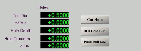
8 5.8 HOLES Holes Move to the center of any hole and select a Rapid or Feed move. Note that this move should be above the work at a safe height. Then select the kind of hole. Hole will mill a hole by making a circular cut. The tool will spiral down to the requested depth, then make a full circle at that depth to fully clear the hole. Be sure you are using a cutter that can be plunged! Drill Hole G81 Peck Drill G83 Zinc. will make a plunge drill operation to the selected depth. will make a peck drill cycle to the selected depth in steps of Page 8 of 17

9 Page 9 of 17

10 Page 10 of 17
11 APPENDIX A COPYCAT QUICK & DIRTY Page 11 of 17
12 APPENDIX B G CODE LIST G1 Linear interpolation G2 Clockwise circular/helical interpolation G3 Counterclockwise circular/helical interpolation G4 Dwell G10 Coordinate system origin setting G12 Clockwise circular pocket G13 Counterclockwise circular pocket G15/G16 Polar Coordinate moves in G0 and G1 G17 XY Plane select G18 XZ plane select G19 YZ plane select G20/G21 Inch/Millimetre unit G28 Return home G28.1 Reference axes G30 Return home G31 Straight probe G40 Cancel cutter radius compensation G41/G42 Start cutter radius compensation left/right G43 Apply tool length offset (plus) G49 Cancel tool length offset G50 Reset all scale factors to 1.0 G51 Set axis data input scale factors G52 Temporary coordinate system offsets G53 Move in absolute machine coordinate system G54 Use fixture offset 1 G55 Use fixture offset 2 G56 Use fixture offset 3 G57 Use fixture offset 4 G58 Use fixture offset 5 G59 Use fixture offset 6 / use general fixture number G61/G64 Exact stop/constant Velocity mode G68/G69 Rotate program coordinate system G70/G71 Inch/Millimetre unit G73 Canned cycle - peck drilling G80 Cancel motion mode G81 Canned cycle - drilling G82 Canned cycle - drilling with dwell G83 Canned cycle - peck drilling G85/G86/G88/G89 Canned cycle G90 Absolute distance mode G90.1 Absolute IJK mode - boring Page 12 of 17
13 G91 Incremental distance mode G91.1 Incremental IJK mode G92 Offset coordinates and set parameters G92.x Cancel G92 etc. G93 Inverse time feed mode G94 Units Per Min. G98 Rapid Height By Z Height G99 Rapid Height By R Height APPENDIX C G0 G1- G2 &G3 and ARC EXPLAINATIONS GO - RAPID MOVE EXPLAINATION (a) For rapid linear motion, program G0 X~ Y~ Z~ A~ B~ C~, where all the axis words are optional, except that at least one must be used. The G0 is optional if the current motion mode is G0. This will produce coordinated linear motion to the destination point at the current traverse rate (or slower if the machine will not go that fast). It is expected that cutting will not take place when a G0 command is executing. (b) If G16 has been executed to set a Polar Origin then for rapid linear motion to a point described by a radius and angle G0 X~ Y~ can be used. X~is the radius of the line from the G16 polar origin and Y~ is the angle in degrees measured with increasing values counterclockwise from the 3 o'clock direction (i.e. the conventional four quadrant conventions). Coordinates of the current point at the time of executing the G16 are the polar origin. l axis words are omitted. If cutter radius compensation is active, the motion will differ from the above; see Cutter Compensation. If G53 is programmed on the same line, the motion will also differ; see Absolute Coordinates. G01 Linear Move (a) For linear motion at feed rate (for cutting or not), program G1 X~ Y~ Z~ A~ B~ C~, where all the axis words are optional, except that at least one must be used. The G1 is optional if the current motion mode is G1. This will produce co - ordinated linear motion to the destination point at the current feed rate (or slower if the machine will not go that fast). Page 13 of 17
14 (b) If G16 has been executed to set a polar origin then linear motion at feed rate to a point described by a radius and angle G0 X~ Y~ can be used. X~ is the radius of the line from the G16 polar origin and is the angle in degrees Y~ measured with increasing values counterclockwise from the 3 o'clock direction (i.e. the conventional four quadrant conventions). Coordinates of the current point at the time of executing the G16 are the polar origin. It is an error if: l axis words are omitted. If cutter radius compensation is active, the motion will differ from the above; see Cutter Compensation. If G53 is programmed on the same line, the motion will also differ; see Absolute Coordinates. G02 & G03 Arc Move A circular or helical arc is specified using either G2 (clockwise arc) or G3 (counterclockwise arc). The axis of the circle or helix must be parallel to the X, Y, or Z -axis of the machine coordinate system. The axis (or, equivalently, the plane perpendicular to the axis) is selected with G17 (Z -axis, XY - plane), G18 (Y -axis, XZ -plane), or G19 (X -axis, YZ -plane). If the arc is circular, it lies in a plane parallel to the selected plane. If a line of code makes an arc and includes rotational axis motion, the rotational axes turn at a constant rate so that the rotational motion starts and finishes when the XYZ motion starts and finishes. Lines of this sort are hardly ever programmed. If cutter radius compensation is active, the motion will differ from the above; see Cutter Compensation. Two formats are allowed for specifying an arc. We will call these the center format and the radius format. In both formats the G2 or G3 is optional if it is the current motion mode. Arc Center Format In the center format, the coordinates of the end point of the arc in the selected plane are specified along with the offsets of the center of the arc from the current location. In this format, it is OK if the end point of the arc is the same as the current point. It is an error if: en the arc is projected on the selected plane, the distance from the current point to the center differs from the distance from the end point to the center by more than inch (if inches are being used) or millimetre (if millimetres are being used). Page 14 of 17
15 The center is specified using the I and J words. There are two ways of interpreting them. The usual way is that I and J are the center relative to the current point at the start of the arc. This is sometimes called Incremental IJ mode The second way is that I and J specify the center as actual coordinates in the current system. This is rather misleadingly called Absolute IJ mod.the IJ mode is set using the Configure>State menu when Mach3 is set up. The choice of modes are to provide compatibility with commercial controllers. You will probably find Incremental to be best. In Absolute it will, of course usually be necessary to use both I and J words unless by chance the arc's centre is at the origin. WI~ J~ (or use G3 instead of G2). The axis words are all optional except that at least one of X and Y must be used. I and J are the offsets from the current l respectively) of the center of the circle. I and J are optional except that at least one of the two must be used. It is an error if: X and Y are both omitted, I and J are both omitted. When the XZ -plane is selected, program G2 X~ Y~ Z~ A~ B~ C~ I~ K~ (or use G3 instead of G2). The axis words are all optional except that at least one of X and Z must be used. I and K are the offsets from the current location or coordinates -depending on IJ mode (X and Z directions, respectively) of the center of the circle. I and K are optional except that at least o X and Z are both omitted, I and K are both omitted. When the YZ -plane is selected, program G2 X~ Y~ Z~ A~ B~ C~ J~ K~ (or use G3 instead of G2). The axis words are all optional except that at least one of Y and Z must be used. J and K are the offsets from the current location or coordinates -depending on IJ mode (Y and Z directions, respectively) of the center of the circle. J and K are optional except that at least one of the two must be used. It is an error if: and K are both omitted. Here is an example of a center format command to mill an arc in Incremental IJ Page 15 of 17
16 mode: G17 G2 x10 y16 i3 j4 z9 That means to make a clockwise (as viewed from the positive z -axis) circular or helical arc whose axis is parallel to th-axis, ending where X=10, Y=16, and Z=9, with its center offset in the X direction by 3 units from the current X location and offset in the Y direction by 4 units from the current Y location. If the current location has X=7, Y=7 at the outset, the center will be at X=10, Y=11. If the starting value of Z is 9, this is a circular arc; otherwise it is a helic arc. The radius of this arc would be 5. The above arc in Absolute IJ mode would be: G In the center format, the radius of the arc is not specified, but it may be found easily as the distance from the center of the circle to either the current point or the end point of the arc. Page 16 of 17
17 APPENDIX D VIDEO WINDOW AND CAMERA Page 17 of 17
Mach4 CNC Controller Mill Programming Guide Version 1.0
 Mach4 CNC Controller Mill Programming Guide Version 1.0 1 Copyright 2014 Newfangled Solutions, Artsoft USA, All Rights Reserved The following are registered trademarks of Microsoft Corporation: Microsoft,
G & M Code REFERENCE MANUAL. Specializing in CNC Automation and Motion Control
 REFERENCE MANUAL Specializing in CNC Automation and Motion Control 2 P a g e 11/8/16 R0163 This manual covers definition and use of G & M codes. Formatting Overview: Menus, options, icons, fields, and
Mach4 CNC Controller Mill Programming Guide Version 1.1 Build 3775
 Mach4 CNC Controller Mill Programming Guide Version 1.1 Build 3775 Copyright 2014 Newfangled Solutions, Artsoft USA, All Rights Reserved The following are registered trademarks of Microsoft Corporation:
Mach4 CNC Controller Lathe Programming Guide Version 1.0
 Mach4 CNC Controller Lathe Programming Guide Version 1.0 1 Copyright 2014 Newfangled Solutions, Artsoft USA, All Rights Reserved The following are registered trademarks of Microsoft Corporation: Microsoft,
Conversational Programming for 6000i CNC
 Conversational Programming for 6000i CNC www.anilam.com P/N 634 755-22 - Contents Section 1 - Introduction Section 2 - Conversational Mode Programming Hot Keys Programming Hot Keys... 2-1 Editing Keys...
CIRCULAR INTERPOLATION COMMANDS
 PROGRAMMING JANUARY 2005 CIRCULAR INTERPOLATION COMMANDS G02 CW CIRCULAR INTERPOLATION MOTION & G03 CCW CIRCULAR INTERPOLATION MOTION *X Circular end point X-axis motion *Y Circular end point Y-axis motion
Conversational Programming for 6000M, 5000M CNC
 Conversational Programming for 6000M, 5000M CNC www.anilam.com P/N 70000486F - Contents Section 1 - Introduction Section 2 - Conversational Mode Programming Hot Keys Programming Hot Keys... 2-1 Editing
ADVANCED TECHNIQUES APPENDIX A
 A P CONTENTS þ Anilam þ Bridgeport þ Fanuc þ Yasnac þ Haas þ Fadal þ Okuma P E N D I X A ADVANCED TECHNIQUES APPENDIX A - 1 APPENDIX A - 2 ADVANCED TECHNIQUES ANILAM CODES The following is a list of Machinist
Mach3. Mach3 Gcode Manual Ultimate Screen Reference Guide
 Mach3 Mach3 Gcode Manual Ultimate Screen Reference Guide Mach3 Gcode Manual 1 Definitions 1.1 Linear Axes The X, Y, and Z axes form a standard right-handed coordinate system of orthogonal linear axes.
Lesson 4 Introduction To Programming Words
 Lesson 4 Introduction To Programming Words All CNC words include a letter address and a numerical value. The letter address identifies the word type. The numerical value (number) specifies the value of
Mach4 Lathe G-Code and M-Code Reference
 Mach4 Lathe G-Code and M-Code Reference Chapter 1: Introduction G-Code is a special programming language that is interpreted by Computer Numerical Control (CNC) machines to create motion and other tasks.
Software designed to work seamlessly with your CNC Masters machine. Made to work with Windows PC. Works with standard USB
 Software designed to work seamlessly with your CNC Masters machine Made to work with Windows PC Works with standard USB Clutter free interface. The software is engineered for the machine so you don t have
Conversational Programming for 6000i CNC
 Conversational Programming for 6000i CNC January 2008 Ve 01 634755-21 1/2008 VPS Printed in USA Subject to change without notice www.anilam.com P/N 634755-21 - Warranty Warranty ANILAM warrants its products
Conversational Programming for 6000M, 5000M CNC
 Conversational Programming for 6000M, 5000M CNC www.anilam.com P/N 70000486E - Warranty Warranty ANILAM warrants its products to be free from defects in material and workmanship for one (1) year from date
CHAPTER 12. CNC Program Codes. Miscellaneous CNC Program Symbols. D - Tool Diameter Offset Number. E - Select Work Coordinate System.
 General CHAPTER 12 CNC Program Codes The next three chapters contain a description of the CNC program codes and parameters supported by the M-Series Control. The M-Series Control has some G codes and parameters
Our thanks go to: Puppy Linux, RTAI, EMC, axis, all the kernel developers and big mama thornton.
 CoolCNC Linux First Steps This manual is a step by step introduction for the installation of the CoolCNC Linux Live CD. Its intent is to lead to a better understanding of the current processes. This document
HAAS AUTOMATION, INC.
 PROGRAMMING WORKBOOK HAAS AUTOMATION, INC. 2800 Sturgis Rd. Oxnard, CA 93030 JUNE 1, 2000 JUNE 2000 PROGRAMMING CONTENTS INTRODUCTION... 1 THE COORDINATE SYSTEM... 2 MACHINE HOME... 5 ABSOLUTE AND INCREMENTAL
ACR-MotionMax Programmer's Reference Manual
 ACR-MotionMax Programmer's Reference Manual Programmer's Reference Manual Programming Information - 1 User Information ACR Series products are used to control electrical and mechanical components of motion
FAGOR AUTOMATION MC TRAINING MANUAL
 FAGOR AUTOMATION MC TRAINING MANUAL ACER MC TRAINING MANUAL 8 holes 1/2" depth grid pattern R0.125 1.5 6 unit: inch R0.25 4 1.25 2 2.675 1/2" depth rectangular pocket 1/2" depth circular pocket R0.75 8
Warranty. Student Workbook for Three-Axis Systems
 www.anilam.com P/N 70000505 - Warranty Warranty ANILAM warrants its products to be free from defects in material and workmanship for one (1) year from date of installation. At our option, we will repair
Polar coordinate interpolation function G12.1
 Polar coordinate interpolation function G12.1 On a Turning Center that is equipped with a rotary axis (C-axis), interpolation between the linear axis X and the rotary axis C is possible by use of the G12.1-function.
PC-BASED NUMERIC CONTROLLER
 Ncstudio PC-BASED NUMERIC CONTROLLER PROGRAMMING MANUAL there is WEIHONG Where there is motion control Thank you for choosing our products! This manual will help you acquaint with our products and learn
IEEM 215. Manufacturing Processes I Introduction to the ARIX CNC milling machine
 IEEM 215. Manufacturing Processes I Introduction to the ARIX CNC milling machine The image below is our ARIX Milling machine. The machine is controlled by the controller. The control panel has several
CNC 8055 MC EXAMPLES MANUAL REF Ref. 0601
 EXAMPLES MANUAL Ref. 0601 All rights reserved. No part of this documentation may be copied, transcribed, stored in a data backup system or translated into any language without Fagor Automation's explicit
NcStudio Programming Manual
 NcStudio Programming Manual 6th Edition Weihong Electronic Technology Co., Ltd. The copyright of this manual belongs to Weihong Electronic Technology Co., Ltd. (hereinafter referred to as Weihong Company).
NC CODE REFERENCE MANUAL
 NC CODE REFERENCE MANUAL Thank you very much for purchasing this product. To ensure correct and safe usage with a full understanding of this product's performance, please be sure to read through this manual
Turning ISO Dialect T
 SINUMERIK 802D Short Guide 09.2001 Edition Turning ISO Dialect T User Documentation SINUMERIK 802D Turning ISO Dialect T Short Guide 09.2001 Edition Valid for Control Software Version SINUMERIK 802D 1
GE FANUC 21 CONCEPT 55 MILL ATC TEACHER GUIDE
 GE FANUC 21 CONCEPT 55 MILL ATC TEACHER GUIDE 11/1/07 Version 2 Made by EMCO Authored by Chad Hawk Training Index Control Keyboard Pg 1 Fanuc 21 Control Machine Control Fanuc 21 Screen. Pg 2 Fanuc 21 Keys.
Section 20: Graphics
 Section 20: Graphics CNC 88HS Graphics Graphics Menu The graphics menu of the page editor has been designed to allow the user to view the part path of the current program in memory. The graphics can be
3300M/MK CNC Programming and Operations Manual
 3300M/MK CNC Programming and Operations Manual www.anilam.com P/N 70000381C - Contents Section 1 - CNC Programming Concepts Programs... 1-1 Axis Descriptions... 1-1 X Axis... 1-2 Y Axis... 1-2 Z Axis...
6000i CNC User s Manual
 6000i CNC User s Manual January 2008 Ve 02 627785-21 1/2008 VPS Printed in USA Subject to change without notice www.anilam.com P/N 627785-21 - Warranty Warranty ANILAM warrants its products to be free
Century Star Turning CNC System. Programming Guide
 Century Star Turning CNC System Programming Guide V3.5 April, 2015 Wuhan Huazhong Numerical Control Co., Ltd 2015 Wuhan Huazhong Numerical Control Co., Ltd Preface Preface Organization of documentation
2000 Series Mill / Router Operating Manual
 2000 Series Mill / Router Operating Manual 1. Introduction 1.1 Control Startup To open the control software double-click on the profile icon on the desktop. Control Icon 1.2 Overview This manual gives
9000 CNC 9000 CNC: THE NEW STANDARD OF CONTROL. INTUITIVE EFFICIENT PRODUCTIVE
 3D Solid Model Graphics Solid Model with Tool Path Overlay 9000 CNC 9000 CNC: THE NEW STANDARD OF CONTROL. At Milltronics we are constantly refining our controls to simplify operation, shorten setup times
5000M CNC Programming and Operations Manual
 5000M CNC Programming and Operations Manual www.anilam.com P/N 70000508G - Warranty Warranty ANILAM warrants its products to be free from defects in material and workmanship for one (1) year from date
COMPUTER NUMERICAL CONTROL OF MACHINE TOOLS
 COMPUTER NUMERICAL CONTROL OF MACHINE TOOLS Department of Mechanical Engineering and Aeronautics University of Patras, Greece Dr. Dimitris Mourtzis Associate professor Patras, 2017 1/52 Chapter 8: Two
CNC USB Controller. User manual
 CNC USB Controller User manual 2010-06-26 1 Table of Contents 1 2 Introduction...8 1.1 Overview...8 1.2 System Requirements...8 Hardware...9 2.1 Specification and features...9 2.2 Board description...10
COMPUTER NUMERICAL CONTROL OF MACHINE TOOLS
 COMPUTER NUMERICAL CONTROL OF MACHINE TOOLS Department of Mechanical Engineering and Aeronautics University of Patras, Greece Dr. Dimitris Mourtzis Associate professor Patras, 2017 1/31 Chapter 13: Advanced
3000M CNC Programming and Operations Manual for Two-Axis Systems
 3000M CNC Programming and Operations Manual for Two-Axis Systems www.anilam.com P/N 70000496G - Contents Section 1 - CNC Programming Concepts Programs... 1-1 Axis Descriptions... 1-1 X Axis... 1-2 Y Axis...
3000M CNC Programming and Operations Manual for Three- and Four-Axis Systems
 3000M CNC Programming and Operations Manual for Three- and Four-Axis Systems www.anilam.com 70000504H - Warranty Warranty ANILAM warrants its products to be free from defects in material and workmanship
CNC PART PROGRAMMING
 CNC PART PROGRAMMING (1) Programming fundamentals Machining involves an important aspect of relative movement between cutting tool and workpiece. In machine tools this is accomplished by either moving
Ultimate Screen Reference Guide
 MACHMOTION Ultimate Screen Reference Guide 8/11/2011 Everything you need to know to use and setup the MachMotion Ultimate Screen. MachMotion Version 1.0.2 2 P a g e Copyright 2011, MachMotion.com All rights
Section 15: Touch Probes
 Touch Probes Touch Probe - Length Offset The tool setting probe is used with the UTILITY command to establish the length offset. It can also be used for tool breakage detection and setting tool diameter
Southwestern Industries, Inc. DPM RX7 Bed Mill Specifications with the ProtoTRAK RMX Control
 Southwestern Industries, Inc. DPM RX7 Bed Mill Specifications with the ProtoTRAK RMX Control Machine Specifications Table size 76 x 14 T-slots (number x width x pitch) 3 x 16mm x 63.5mm Travel (X, Y, Z
MAX CONTROL FOR TURNING CENTERS
 MAX CONTROL FOR TURNING CENTERS Preliminary NC Programming Manual March 2005 PRE 704-0115-301, B Revision B The information in this document is subject to change without notice and does not represent a
TOOLPATHS TRAINING GUIDE. Sample. Distribution. not for MILL-LESSON-4-TOOLPATHS DRILL AND CONTOUR
 TOOLPATHS TRAINING GUIDE MILL-LESSON-4-TOOLPATHS DRILL AND CONTOUR Mill-Lesson-4 Objectives You will generate a toolpath to machine the part on a CNC vertical milling machine. This lesson covers the following
6 Series Mill Controller Operation Manual
 6 Series Mill Controller Operation Manual Date: 2015/11/13 Version: 1.3 2 Contents 1 Function Key and System Configuration... 4 1.1 Main Screen Sections... 4 1.2 CNC System Configuration... 5 1.3 Coordinate...
OEM Buttons - MachCustomizeWiki
 Page 1 of 8 OEM Buttons From MachCustomizeWiki This list gives the codes to be used in calls of DoOEMButton. If you are using a version of Mach3 prior to 1.90 then to use bunttons in this list that are
4.10 INVOLUTE INTERPOLATION (G02.2, G03.2)
") B 63014EN/02 POGAMMNG 4. NTEPOLATON FUNCTONS 4.10 NVOLUTE NTEPOLATON (G02.2, G03.2) nvolute curve machining can be performed by using involute interpolation. nvolute interpolation ensures continuous pulse
B 63014EN/02 POGAMMNG 4. NTEPOLATON FUNCTONS 4.10 NVOLUTE NTEPOLATON (G02.2, G03.2) nvolute curve machining can be performed by using involute interpolation. nvolute interpolation ensures continuous pulse
Excellon Automation Co. - Leading Manufacturer of PCB Drills&Routers
 Page 1 of 37 Sunday 11.11.2007 CALL +1 310.668.7700 PARTS ORDER +1 800.EXCELLON APPLICATIONS SUPPORT User Manuals Drill Fundamentals Drill Parameter Part Programs Unix Help For UCS Machine Setup Commands
Programming Features PERFORMANCE & SPECIFICATIONS
 PERFORMANCE & SPECIFICATIONS Essentials Processor Intel Pentium Instruction Set 32-bit Performance Number of Cores 1 Processor Base Frequency 1.8 GHz Memory Data Storage 1 GB System Memory Installed 2
CENTROID. M-SERIES Operator's Manual. Version 8.22 Rev U.S. Patent # Centroid Corp. Howard, PA 16841
 CENTROID M-SERIES Operator's Manual Version 8.22 Rev. 030826 U.S. Patent #6490500 2004 Centroid Corp. Howard, PA 16841 CNC Control Information Sheet Fill out the following and fax back to Centroid Tech
6 Series Mill Controller Operation Manual
 6 Series Mill Controller Operation Manual Date: 2013/10/25 Version: 1.1 Contents 1 Function Key and System Configuration... 4 1.1 Main Screen Sections... 4 1.2 CNC System Configuration... 5 1.3 Coordinate...
Computer Aided Engineering Applications 3. Advanced Manufacturing 3.5 NC programming 3.6 Automated Manufacturing systems 3.7 Rapid prototyping
 Computer Aided Engineering Applications 3. Advanced Manufacturing 3.5 NC programming 3.6 Automated Manufacturing systems 3.7 Rapid prototyping Engi 6928 - Fall 2014 3.5 Part programming Structure of an
VERO UK TRAINING MATERIAL. 2D CAM Training
 VERO UK TRAINING MATERIAL 2D CAM Training Vcamtech Co., Ltd 1 INTRODUCTION During this exercise, it is assumed that the user has a basic knowledge of the VISI-Series software. OBJECTIVE This tutorial has
MillMaster Pro. able of Contents. 1. Getting Started. ted. 2. Menu Descriptions
 Tab able of Contents 1. Getting Started ted Introduction... 3 2. Menu Descriptions 2.1 File Menu... 7 2.2 Switch Menu... 11 2.3 View Menu... 12 2.4 Control Menu... 15 2.5 Run Menu... 17 2.6 Tools Menu...
Manufacturing Processes with the Aid of CAD/CAM Systems AMEM 405
 AMEM 405 slide 1 Manufacturing Processes with the Aid of CAD/CAM Systems AMEM 405 Dr. Sotiris Omirou AMEM 405 slide 2 CONTENTS 1. CAD/CAM definition 2. Review of Milling Process 3. Know The CNC Machine
Part Programming Manual MACHINEMATE
 MACHINEMATE NOTE Progress is an ongoing commitment at MACHINEMATE INC. We continually strive to offer the most advanced products in the industry. Therefore, information in this document is subject to change
ND 7000 Demo. User s Manual. Digital Readout
 ND 7000 Demo User s Manual Digital Readout English (en) 11/2018 Contents Contents 1 Fundamentals...7 2 Software installation...11 3 Basic operation... 17 4 Software configuration... 43 5 Milling Quick
Mach4 CNC Controller Screen Editing Guide Version 1.0
 Mach4 CNC Controller Screen Editing Guide Version 1.0 1 Copyright 2014 Newfangled Solutions, Artsoft USA, All Rights Reserved The following are registered trademarks of Microsoft Corporation: Microsoft,
ADT-CNC4940 CNC4940 Milling Machine Control System. Programming Manual
 ADT-CNC4940 CNC4940 Milling Machine Control System Programming Manual Adtech (Shenzhen) Technology Co., Ltd. Add: F/5, Bldg/27-29, Tianxia IC Industrial Park, Yiyuan Rd, Nanshan District, Shenzhen Postal
Addendum for Acromill 15.00
 Addendum for Acromill 15.00 Objective... 1 Differences between previous versions and version 15.00... 3 New Commands... 5 IF COMMAND...5 WHILE COMMAND...5 $I INCLUDE FILE COMPILER DIRECTIVE...5 G9 EXACT
Mill Level 1 Training Tutorial
 To order more books: Call 1-800-529-5517 or Visit www.inhousesolutions.com or Contact your Mastercam dealer Mastercam X 5 Copyright: 1998-2010 In-House Solutions Inc. All rights reserved Software: Mastercam
M-SERIES Operator s Manual
 M-SERIES Operator s Manual CNC12 Version 4.12 U.S. Patent #6490500 c 2018 Centroid Corp. Howard, PA 16841 Throughout this manual and on associated products where applicable, in accordance with ANSI Z535,
Introduction to Word Address Programming
 Chapter 1 Introduction to Word Address Programming 1.1 Objectives After completion of this chapter the reader will be able to: 1. Understand the meaning of common terminology associated with writing a
CNC Programming Simplified. EZ-Turn Tutorial.
 CNC Programming Simplified EZ-Turn Tutorial www.ezcam.com Copyright Notice This manual describes software that contains published and unpublished works of authorship proprietary to EZCAM Solutions, Inc.
Welcome to. the workshop on the CNC 8055 MC
 Welcome to the workshop on the CNC 8055 MC Sales Dpt-Training: 2009-sept-25 FAGOR CNC 8055MC seminar 1 Sales Dpt-Training: 2009-sept-25 FAGOR CNC 8055MC seminar 2 This manual is part of the course for
CAD2Gcode DXF Writer By Bob Adams
 CAD2Gcode DXF Writer By Bob Adams No need to learn CAD To make a part you would sketch your idea on paper first. Then making a drawing using a CAD program. Saving as a DXF file to convert, using a gcode
dfab Laguna CNC Manual With FANUC Control
 dfab Laguna CNC Manual With FANUC Control 1 Introduction Throughout this manual we use different nomenclature for [HARD KEYS] and (SOFT KEYS). A [HARD KEY] is a button on the CONTROL PANEL (upper panel)
Vectric Cut 3D (Frogmill)
") II. Subtractive Rapid Prototyping / VECTRIC CUT 3D (Frogmill) SUBTRACTIVE RAPID PROTOTYPING Vectric Cut 3D (Frogmill) INTERFACE: VECTRIC CUT 3D Model: Frogmill Size: W3050 x D1828 X H419 Material: EPS
II. Subtractive Rapid Prototyping / VECTRIC CUT 3D (Frogmill) SUBTRACTIVE RAPID PROTOTYPING Vectric Cut 3D (Frogmill) INTERFACE: VECTRIC CUT 3D Model: Frogmill Size: W3050 x D1828 X H419 Material: EPS
CNC Knee Type Milling Machines with USA CENTROID M-400S CNC control
 CNC Knee Type Milling Machines with USA CENTROID M-400S CNC control GMM-949-CNC, 9 x49 table, R8, vari-speed, 3 axis CNC... GMM-949F-CNC, 9 x49 table, R8, inverter drive, 5,000 rpm, 3 axis CNC.. Note:
 PROGRAMMING WORKBOOK HAAS AUTOMATION, INC 2800 Sturgis Rd Oxnard, CA 93030 January 2004 JANUARY 2004 PROGRAMMING HAAS AUTOMATION INC 2800 Sturgis Road Oxnard, California 93030 Phone: 805-278-1800 www
Demonstration -3D Printer -CNC Milling Machine
 Demonstration -3D Printer -CNC Milling Machine ENGINEERING LABORATORY EE-100 Lahore University of Management Sciences Electrical Engineering Department, SSE Non-conventional Manufacturing 3D Printing A
User s Manual V MillPlus IT. NC Software
 User s Manual V600-02 MillPlus IT NC Software 538 952-02 538 953-02 538 954-02 538 955-02 538 956-02 English (en) 6/2008 Controls on the visual display unit Select window User keys Manual operation Axis-direction
Mach4 Industrial Mill Operations Guide
 Mach4 Industrial Mill Operations Guide 1 Copyright 2014 Newfangled Solutions, Artsoft USA, All Rights Reserved The following are registered trademarks of Microsoft Corporation: Microsoft, Windows. Any
Coordinate System Techniques
 Coordinate System Techniques In this lesson, we ll show some advanced implications of what can be done with coordinate systems. For the most part, this lesson applies to machining centers. But there are
Standard Mach4 Features included with Tangential:
 MACH4 TANGENTIAL Tangential takes place on one page: Program Run. The Tangential Profile is intended to operate Machinery equipped with a rotational axis independent of, but usually associated in, the
CNC Programming Simplified. EZ-Turn / TurnMill Tutorial.
 CNC Programming Simplified EZ-Turn / TurnMill Tutorial www.ezcam.com Copyright Notice This manual describes software that contains published and unpublished works of authorship proprietary to EZCAM Solutions,
SINUMERIK 802D. Brief Instructions Edition. Milling. User Documentation
 SINUMERIK 802D Brief Instructions Milling 11.2000 Edition User Documentation SINUMERIK 802D Milling Valid for Control Software version SINUMERIK 802D 1 11.2000 Edition SINUMERIK documentation Printing
Using Delcam Powermill
 Written by: John Eberhart & Trevor Williams DM Lab Tutorial Using Delcam Powermill Powermill is a sophistical tool path generating software. This tutorial will walk you through the steps of creating a
300S READOUTS REFERENCE MANUAL
 300S READOUTS REFERENCE MANUAL 300S Key Layout 1 Display Area 2 Soft keys 3 Power Indicator light 4 Arrow Keys: Use the UP/DOWN keys to adjust the screen contrast. 5 Axis Keys 6 Numeric Keypad 7 ENTER
Dolphin 3DCAM Help. Copyright <2018> by <Dolphin Cadcam Systems Ltd>. V All Rights Reserved.
 Copyright by . V1.020216 All Rights Reserved. Table of Contents Introduction... 3 Getting Started... 4 The Ribbon Toolbar... 5 File... 6 Geom... 9 Solids... 24 View...
GE FANUC 21 CONCEPT 55 TURN TEACHER GUIDE
 GE FANUC 21 CONCEPT 55 TURN TEACHER GUIDE 2/13/08 Version 2 Made by EMCO Authored by Chad Hawk Training Index Control Keyboard Pg 1 Fanuc 21 Control Machine Control Fanuc 21 Screen Pg 2 Fanuc 21 Keys Pg
Digital display for EMCO milling machines
 Digital display for EMCO milling machines Input box 7 8 9 1 X Y Z HELP 4 5 6 1 2 3 0. - ESC 3 CE ENT R + R - 2 REF RST 1... Screen (working window, displays) 2... 5 soft keys (function depends on the respective
Xbox gamepad CNC pendant user manual
 Patrik Tegelberg 2017-09-04 Xbox gamepad CNC pendant user manual Computer controlled manufacturing machines are awesome, and not designed for manual cutting. This controller, for LinuxCNC, maintains the
All text and images copyright of Marcus Bowman except where stated otherwise. ø4 3. Part 11
 All text and images copyright of Marcus Bowman except where stated otherwise. ø4 3 11 19 R3 ø4 Part 11 2 Part 11 In this part of the series, we continue looking at circular paths but find out how to re-use
Tutorial: Basic G Code Programming By: Matthew Jourden Brighton High School Brighton, MI
 Tutorial: Basic G Code Programming By: Matthew Jourden Brighton High School Brighton, MI Reference: Coordinate Axis Direction Z Y X Tutorial is designed to create a wireframe model of a part. This tutorial
Exercise Guide. Published: August MecSoft Corpotation
 VisualCAD Exercise Guide Published: August 2018 MecSoft Corpotation Copyright 1998-2018 VisualCAD 2018 Exercise Guide by Mecsoft Corporation User Notes: Contents 2 Table of Contents About this Guide 4
CNC 8055 M. Error solution. Ref.1705
 CNC 8055 M Error solution All rights reserved. No part of this documentation may be transmitted, transcribed, stored in a backup device or translated into another language without Fagor Automation s consent.
GE Fanuc Automation. Series 16i / 18i / 21i Model TA Manual Guide. Computer Numerical Control Products. Operator's Manual
 GE Fanuc Automation Computer Numerical Control Products Series 16i / 18i / 21i Model TA Manual Guide Operator's Manual B-63344EN/01 July 1998 Warnings, Cautions, and Notes as Used in this Publication GFL-001
HDS Series Quick Start Guide.
 Techno-Osai Start Up Sequence HDS Series Quick Turn the Main power switch to the ON Position. 220 volts should have been attached to this switch by an electrician. Power On Button. Computer power ON. The
Introduction CAUTION. Details described in this manual
 Introduction This manual is a guide for using the MELDAS 60/60S Series, MELDASMAGIC64. Programming is described in this manual, so read this manual thoroughly before starting programming. Thoroughly study
Craftsman CNC. LinuxCNC. Custom developed for Craftsman CNC Routers
 Craftsman CNC LinuxCNC Custom developed for Craftsman CNC Routers Menu File Load gcode Load a gcode program Recent gcode Shows the 10 most recently opened gcode programs Close gcode Closes the current
Pilot TNC 426. NC-Software xx xx 1/97
 Pilot TNC 426 NC-Software 280 462 xx 280 463 xx 1/97 The Pilot... is your concise programming guide for the HEIDENHAIN TNC 426 CA and TNC 426 PA contouring controls. For more comprehensive information
Ladybird Project - Vacuum Mould
 - Vacuum Mould Prerequisite Mould drawn and saved as STL file from Solidworks Focus of the Lesson On completion of this exercise you will have completed: Opening STL file Setting Machining Constraints
Wizard 1000 REFERENCE MANUAL
 Wizard 1000 REFERENCE MANUAL W1000 Key Layout Display Area Axis Keys Numeric Keypad Clear key Soft keys Enter key Power Indicator light Arrow keys - Up/ Down arrow keys are also used to adjust the screen
This manual describes the various matters concerning the. operations of this CNC system as much as possible. However, it is
 This manual describes the various matters concerning the operations of this CNC system as much as possible. However, it is impossible to give detailed descriptions to all the unnecessary or unallowable
I Document: PIN Version: Programming, Operating & Care Manual
 Programming, Operating & Care Manual I Document: PIN 2031 7 Version: 0401 97 SOUTHWESTERN INDUSTRIES, INC. 2605 Homestead Place Rancho Dominguez, California 90220 Tel (310) 608-4422 1 Fax (310) 764-2668
TRAINING GUIDE MILL-LESSON-FBM-1 FBM MILL AND FBM DRILL
 TRAINING GUIDE MILL-LESSON-FBM-1 FBM MILL AND FBM DRILL Mastercam Training Guide Objectives Previously in Mill-Lesson-6 and Mill-Lesson-7 geometry was created and machined using standard Mastercam methods.
12. Rotary Retract Movement Setup Clearance Tool Change X Safe Positions Custom Settings Reference
 NMV This manual was prepared with the assumption that the intended reader does have working knowledge of Esprit and NMV programming experience so that he fully understands the information it contains.