Demonstration -3D Printer -CNC Milling Machine
|
|
|
- Emily Hampton
- 6 years ago
- Views:
Transcription

1 Demonstration -3D Printer -CNC Milling Machine ENGINEERING LABORATORY EE-100 Lahore University of Management Sciences Electrical Engineering Department, SSE
2 Non-conventional Manufacturing 3D Printing A process of making a three-dimensional solid object of virtually any shape from a digital model. A 3D printer is a limited type of industrial robot that is capable of carrying out an additive process under computer control.

3
4 Creating.stl file from CAD Create your model in PTC Creo. Save your part file as.prt Then Proceed as: File > Save As > File type stl, then Enter a file name. A dialog box will appear for the information of Chord height and Angle Control. Values for Chord Height and Angle Control determine the triangulation mesh. Small numbers make a fine mesh (larger file size), larger numbers yield a coarse mesh (smaller file size).

5

6 Triangular Mesh of the Model
7 Generating the Machine Specific File We will be creating the.cubex files for our CUBE 3D Printing Machine. Open your saved.stl file in the CUBEX environment. Adjust: Material Cartridge Part Placement Printing Scales/ Dimensions Layer Thickness (This would affect the printing resolution) Part Density Support Material

8

9 Build File

10 Results: Build Complete

11 Save the Print file as.cubex
12 CNC Milling Machine CNC Milling Machine CNC machine is a Computerized Numerically Controlled machining process of using rotary cutters to remove material. Lab Apparatus of CNC Milling: SHARPE SXK01 is a desktop type, prototype making CNC machine. The machine is a multifunctional and cost effective apparatus with the following specifications: Three-dimensional numerical control tool path to simulation experiment. High-performance Mach3 control system. Manual direction to prepare G code to complete the processing of desired part.

13
14 Machine Coordinate System The upward and downward movement of the machine has been marked as the Z- axis. Latitude on the horizontal plane has been specified as the X-axis and longitude has been marked as the Y-axis. The machine movements are scaled as per the machine units. 1 cm = 1.4 units on X- axis of mill machine. 1 cm = 2 units on Y- axis of mill machine. Machine has the total limitations on all the co-ordinates, i.e. Total movement limitation on X-axis = 24.3 units Total movement limitation on Y-axis = 17.3 units Total movement limitation on Z -axis = 30 units Machine coordinates and zero position can be specified by manual adjustments. Right and Left arrows on keyboard correspond to the X- axis of the machine. Up and Down arrows on keyboard correspond to the Y- axis of the machine. Page Up and Page Down arrows on keyboard correspond to the Z- axis of the machine.

15 Mach Mill 3 Simulator Here are the basic Mach Mill simulators controls, described with their functions:
16 Here are the basic Mach Mill simulators controls, described with their functions: Loading a file Pressing this button would open a file opening wizard. Cycle Start Cycle Start button would execute the loaded G -code Tool Information This button on Mach Mill displays the current tool info. Spindle Speed Other than CNC machine control and G code instructions, spindle speed can be controlled through the simulator control. Feed Rate Other than CNC machine control and G code instructions, feed rate can be controlled through the simulator control. Display Area This area marks tool positions. A complete tool path, with step by step moving points is shown in this area. Zero Reference Configuration of Milling Machine Student can adjust the specific reference point for individual work piece. By manually adjusting the X-Y-Z positions of machine tool on the work piece, press the button of REF ALL HOME on Mach Mill Simulator. The specific X-Y-Z positions would be saved as the zero point / reference of the machine.
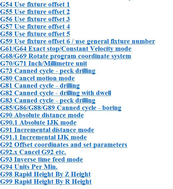
17 Machine G/M Code for the Task G-Codes are prepared in TXT files. These codes can either be manually prepared, just like machine language computer program or can be directly simulated from CAD softwares like PTC CREO Syntax and Explanation of most commonly used commands: Command: G01 Explanation: Linear motion with feed rate Syntax: G01 F10 X00 Y00 Z00 S00 F=Feed Rate S= Spindle Speed X00 Y00 Z00= Arguments for the command Command: G00 Explanation: Rapid Positioning Syntax: G00 X00 Y00 Z00 X00 Y00 Z00= Arguments for the command Command: G28 Explanation: Go to the home position of the machine Syntax: G28 Details of all G-codes are given below in the Appendix A, and M Codes in the Appendix B, below. You can also check their explanations from Mach Mill 3, while working on them.
18 GCodes Example Below given figure shows, isometric view of a plate having 1 slot and 2 holes to be drilled in the plate. Dimensions are presented in standard position coordinates. The diameter of milling tool is 4.5. The depth of machining is 5. GCodes: G00 - Positioning G01 - Straight interpolation
19
20 (Length=70 Width=50 Thickness=5) (Material=Aluminium FeedRate=10 ToolDia=4.5) G28 (Go to home) M03 S1000 (Clockwise spindle at 1000) (Drill Hole, 1) G00 X04.50 Y04.50 Z00.00 G01 Z F10.00 G00 Z00.00 (Drill Hole, 2) G00 X11.00 Y04.50 Z00.00 G01 Z F10.00 G00 Z00.00 (Straight Slot, 3) G00 X17.50 Y04.50 Z00.00 G01 Z F10.00 G01 X52.50 Y04.50 G28 (Go to home) M05 (Stop Spindle) M30 (Program End)
21 Demonstration
22 Lab Task

23 Appendix A: G- Code All the G codes are explained with their description
24

25 Appendix B: M- Code All the M codes are explained with their description

26
VisualCAM 2018 for SOLIDWORKS-TURN Quick Start MecSoft Corporation
 2 Table of Contents Useful Tips 4 What's New 5 Videos & Guides 6 About this Guide 8 About... the TURN Module 8 Using this... Guide 8 Getting Ready 10 Running... VisualCAM for SOLIDWORKS 10 Machining...
Vectric Cut 3D (Frogmill)
") II. Subtractive Rapid Prototyping / VECTRIC CUT 3D (Frogmill) SUBTRACTIVE RAPID PROTOTYPING Vectric Cut 3D (Frogmill) INTERFACE: VECTRIC CUT 3D Model: Frogmill Size: W3050 x D1828 X H419 Material: EPS
II. Subtractive Rapid Prototyping / VECTRIC CUT 3D (Frogmill) SUBTRACTIVE RAPID PROTOTYPING Vectric Cut 3D (Frogmill) INTERFACE: VECTRIC CUT 3D Model: Frogmill Size: W3050 x D1828 X H419 Material: EPS
Computer Aided Engineering Applications 3. Advanced Manufacturing 3.5 NC programming 3.6 Automated Manufacturing systems 3.7 Rapid prototyping
 Computer Aided Engineering Applications 3. Advanced Manufacturing 3.5 NC programming 3.6 Automated Manufacturing systems 3.7 Rapid prototyping Engi 6928 - Fall 2014 3.5 Part programming Structure of an
COPYCAT NEW FANGLED SOLUTIONS 2/6/2009
 1.0 INTRODUCTION 1.1 CopyCat is a unique wizard used with MACH3. It is not a stand alone program. This wizard will allow you to jog a machine around and create a Gcode file from the movement. 2.0 REQUIREMENTS
TUTORIAL 3DESIGN. Gravotech SAS-Type3
 TUTORIAL 3DESIGN Gravotech SAS-Type3 Satellite Ring Creation time: 45 minutes Level: Beginner This exercise will be done with the following material: Precious metal, Gold 18k White gold 2 A.RING SHANK
Feature-based CAM software for mills, multi-tasking lathes and wire EDM. Getting Started
 Feature-based CAM software for mills, multi-tasking lathes and wire EDM www.featurecam.com Getting Started FeatureCAM 2015 R3 Getting Started FeatureCAM Copyright 1995-2015 Delcam Ltd. All rights reserved.
Ladybird Project - Vacuum Mould
 - Vacuum Mould Prerequisite Mould drawn and saved as STL file from Solidworks Focus of the Lesson On completion of this exercise you will have completed: Opening STL file Setting Machining Constraints
Mach4 CNC Controller Mill Programming Guide Version 1.0
 Mach4 CNC Controller Mill Programming Guide Version 1.0 1 Copyright 2014 Newfangled Solutions, Artsoft USA, All Rights Reserved The following are registered trademarks of Microsoft Corporation: Microsoft,
We can use square dot paper to draw each view (top, front, and sides) of the three dimensional objects:
 of the three dimensional objects:") Unit Eight Geometry Name: 8.1 Sketching Views of Objects When a photo of an object is not available, the object may be drawn on triangular dot paper. This is called isometric paper. Isometric means equal
Unit Eight Geometry Name: 8.1 Sketching Views of Objects When a photo of an object is not available, the object may be drawn on triangular dot paper. This is called isometric paper. Isometric means equal
Manufacturing Processes with the Aid of CAD/CAM Systems AMEM 405
 AMEM 405 slide 1 Manufacturing Processes with the Aid of CAD/CAM Systems AMEM 405 Dr. Sotiris Omirou AMEM 405 slide 2 CONTENTS 1. CAD/CAM definition 2. Review of Milling Process 3. Know The CNC Machine
CNC 8055 MC EXAMPLES MANUAL REF Ref. 0601
 EXAMPLES MANUAL Ref. 0601 All rights reserved. No part of this documentation may be copied, transcribed, stored in a data backup system or translated into any language without Fagor Automation's explicit
1. Study the image below and table on the next page. Complete the following tasks.
 Activity 8.2 Parametric Constraints Introduction Have you ever received an advertisement in the mail that looked like it was tailored specifically for you? How could the company afford to spend so much
12. Rotary Retract Movement Setup Clearance Tool Change X Safe Positions Custom Settings Reference
 NMV This manual was prepared with the assumption that the intended reader does have working knowledge of Esprit and NMV programming experience so that he fully understands the information it contains.
Activity 8.2a Parametric Constraints
 Page 1 of 10 Activity 8.2a Parametric Constraints (Button Maker) Introduction Have you ever received an advertisement in the mail that looked like it was tailored specifically for you? How could the company
Prototext 4. Why use Prototext 4
 Prototext 4 Prototext is a simple & affordable windows based program for custom engraving used with 2 & 3 axis CNC milling machines. Prototext has been used by machinists for over 15 years. Up till now
Lesson 4 Introduction To Programming Words
 Lesson 4 Introduction To Programming Words All CNC words include a letter address and a numerical value. The letter address identifies the word type. The numerical value (number) specifies the value of
SolidCAM Training Course: Turning & Mill-Turn
 SolidCAM Training Course: Turning & Mill-Turn imachining 2D & 3D 2.5D Milling HSS HSM Indexial Multi-Sided Simultaneous 5-Axis Turning & Mill-Turn Solid Probe SolidCAM + SolidWorks The Complete Integrated
TRAINING GUIDE MILL-LESSON-FBM-2 FBM MILL AND FBM DRILL
 TRAINING GUIDE MILL-LESSON-FBM-2 FBM MILL AND FBM DRILL Mastercam Training Guide Objectives This lesson will use the same Feature Based Machining (FBM) methods used in Mill-Lesson- FBM-1, how ever this
Activity Parametric Constraints
 Activity 2.3.2 Parametric Constraints Introduction Have you ever received an advertisement in the mail that looked like it was tailored specifically for you? How could the company afford to spend so much
EML 2322L -- MAE Design and Manufacturing Laboratory. CNC Machining
 EML 2322L -- MAE Design and Manufacturing Laboratory CNC Machining Intro to CNC Machining CNC stands for computer numeric controlled. It refers to any machine tool (i.e. mill, lathe, drill press, etc.)
Dolphin PartMaster Milling
 Dolphin PartMaster Milling Copyright 2000-2017 Dolphin CadCam Systems Ltd.. This document is copyrighted and all rights are reserved. This document may not, in whole or in part, be copied or reproduced
Software designed to work seamlessly with your CNC Masters machine. Made to work with Windows PC. Works with standard USB
 Software designed to work seamlessly with your CNC Masters machine Made to work with Windows PC Works with standard USB Clutter free interface. The software is engineered for the machine so you don t have
Chapter 36. Mastercam Jewelry Box Fixture. A. Sketch Fixture Rectangle. Step 1. If necessary start a new Mastercam file, click New
 Mastercam 2017 Chapter 36 Jewelry Box Fixture A. Sketch Fixture Rectangle. Step 1. If necessary start a new Mastercam file, click New (Ctrl-N) on the Quick Access Toolbar QAT. Step 2. On the Wireframe
Conversational Programming for 6000i CNC
 Conversational Programming for 6000i CNC www.anilam.com P/N 634 755-22 - Contents Section 1 - Introduction Section 2 - Conversational Mode Programming Hot Keys Programming Hot Keys... 2-1 Editing Keys...
G & M Code REFERENCE MANUAL. Specializing in CNC Automation and Motion Control
 REFERENCE MANUAL Specializing in CNC Automation and Motion Control 2 P a g e 11/8/16 R0163 This manual covers definition and use of G & M codes. Formatting Overview: Menus, options, icons, fields, and
TOOLPATHS TRAINING GUIDE. Sample. Distribution. not for MILL-LESSON-4-TOOLPATHS DRILL AND CONTOUR
 TOOLPATHS TRAINING GUIDE MILL-LESSON-4-TOOLPATHS DRILL AND CONTOUR Mill-Lesson-4 Objectives You will generate a toolpath to machine the part on a CNC vertical milling machine. This lesson covers the following
4 & 5 Axis Mill Training Tutorials. To order more books: Call or Visit or Contact your Mastercam Dealer
 4 & 5 Axis Mill Training Tutorials To order more books: Call 1-800-529-5517 or Visit www.inhousesolutions.com or Contact your Mastercam Dealer Mastercam X Training Tutorials 4 & 5 Axis Mill Applications
2000 Series Mill / Router Operating Manual
 2000 Series Mill / Router Operating Manual 1. Introduction 1.1 Control Startup To open the control software double-click on the profile icon on the desktop. Control Icon 1.2 Overview This manual gives
GENIO CAD/CAM software powered by Autodesk technology for parametric programming of boring, routing and edge-banding work centers Genio SPAI SOFTWARE
 GENIO CAD/CAM software powered by Autodesk technology for parametric programming of boring, routing and edge-banding work centers Overview is a powerful CAD/CAM system powered by Autodesk 3D environment
B-Field Scanner Software
 B-Field Scanner Software Software of the KLIPPEL R&DSYSTEM ( Document Revision 1.2) FEATURES Fully automated measurement process User friendly dedicated templates Uses Klippel db-lab and Robotics software
Chapters. 1. Overview Getting started Step wise guide to code generator... 6
 Chapters 1. Overview... 2 2. Getting started... 3 3. Step wise guide to code generator... 6 1 Overview Introduction PrimeTurning is a new methodology which enables you to do turning in all directions in
Introduction to Solid Modeling
 Introduction to Solid Modeling Parametric Modeling 1 Why draw 3D Models? 3D models are easier to interpret. 3D models can be used to perform engineering analysis, finite element analysis (stress, deflection,
CNC PART PROGRAMMING
 CNC PART PROGRAMMING (1) Programming fundamentals Machining involves an important aspect of relative movement between cutting tool and workpiece. In machine tools this is accomplished by either moving
Mach4 CNC Controller Lathe Programming Guide Version 1.0
 Mach4 CNC Controller Lathe Programming Guide Version 1.0 1 Copyright 2014 Newfangled Solutions, Artsoft USA, All Rights Reserved The following are registered trademarks of Microsoft Corporation: Microsoft,
MFG12197 FeatureCAM Hands On Milling, turning and mill turn with Feature Based Machining
 MFG12197 FeatureCAM Hands On Milling, turning and mill turn with Feature Based Machining Jeremy Malan Delcam Learning Objectives Learn how to instantly machine parts once their features are defined Learn
What s new in EZCAM Version 18
 CAD/CAM w w w. e z c a m. com What s new in EZCAM Version 18 MILL: New Curve Machining Wizard A new Curve Machining Wizard accessible from the Machining menu automates the machining of common part features
Prices. Become a desktop 3D system expert and open up the creative possibilities CNC has to offer. Stable compact 3D system. Reliable and accurate
 s Prices Become a desktop 3D system expert and open up the creative possibilities CNC has to offer. Stable compact 3D system Reliable and accurate Modular multifunctional system Router 3D Printer Foam
CAD/CAM DESIGN TOOLS. Software supplied with all new and upgraded Boxford Lathes, Mills and Routers
 CAD/CAM DESIGN TOOLS Software supplied with all new and upgraded Boxford Lathes, Mills and Routers The Boxford CAD/CAM Design Tools software is a unique suite of integrated CAD and CAM tools designed specifically
CNC Programming Simplified. EZ-Turn / TurnMill Tutorial.
 CNC Programming Simplified EZ-Turn / TurnMill Tutorial www.ezcam.com Copyright Notice This manual describes software that contains published and unpublished works of authorship proprietary to EZCAM Solutions,
VisualMILL Getting Started Guide
 VisualMILL Getting Started Guide Welcome to VisualMILL Getting Started Guide... 4 About this Guide... 4 Where to go for more help... 4 Tutorial 1: Machining a Gasket... 5 Introduction... 6 Preparing the
Copyright 2019 OPEN MIND Technologies AG
 Copyright 2019 OPEN MIND Technologies AG This document applies to hypermill and hypermill SHOP Viewer. It contains notes about recent changes that are not described in the manual. All rights reserved.
This document shows you how to set the parameters for the ModuleWorks Material Removal Simulation.
 Table of Contents Introduction:... 3 Select Profile:... 4 Tool Table - Create Tool(s)... 5 Tool properties:... 5 Tool Color R/G/B:... 6 Simulation Configurations - create stock... 7 What if plugin is greyed
(Refer Slide Time: 00:01:27 min)
") Computer Aided Design Prof. Dr. Anoop Chawla Department of Mechanical engineering Indian Institute of Technology, Delhi Lecture No. # 01 An Introduction to CAD Today we are basically going to introduce
Computer Aided Design Prof. Dr. Anoop Chawla Department of Mechanical engineering Indian Institute of Technology, Delhi Lecture No. # 01 An Introduction to CAD Today we are basically going to introduce
Mach4 CNC Controller Mill Programming Guide Version 1.1 Build 3775
 Mach4 CNC Controller Mill Programming Guide Version 1.1 Build 3775 Copyright 2014 Newfangled Solutions, Artsoft USA, All Rights Reserved The following are registered trademarks of Microsoft Corporation:
Exercise Guide. Published: August MecSoft Corpotation
 VisualCAD Exercise Guide Published: August 2018 MecSoft Corpotation Copyright 1998-2018 VisualCAD 2018 Exercise Guide by Mecsoft Corporation User Notes: Contents 2 Table of Contents About this Guide 4
Linear Interpolation and Dwell Cycle. Dr. Belal Gharaibeh
 Linear Interpolation and Dwell Cycle Dr. Belal Gharaibeh 1 Linear Interpolation Linear interpolation is used in part programming to make a straight cutting motion from the start position of the cut to
Variable Techniques. What are variables?
 Variable Techniques Discussions in lesson one are rather broad in nature. The points made can be applied to any version of parametric programming. From this chapter on, we offer much more specific information.
MANUFACTURING PROCESSES
 MANUFACTURING PROCESSES - AMEM 201 Lecture 7: CNC MACHINE TOOLS 1 CNC MACHINE TOOLS TERMINOLOGY NC Numerical Control CNC Computer Numerical Control CAD Computer Aided Design CAM Computer Aided Manufacturing
COMPUTER NUMERICAL CONTROL OF MACHINE TOOLS
 COMPUTER NUMERICAL CONTROL OF MACHINE TOOLS Department of Mechanical Engineering and Aeronautics University of Patras, Greece Dr. Dimitris Mourtzis Associate professor Patras, 2017 1/52 Chapter 8: Two
Conversational Programming for 6000M, 5000M CNC
 Conversational Programming for 6000M, 5000M CNC www.anilam.com P/N 70000486F - Contents Section 1 - Introduction Section 2 - Conversational Mode Programming Hot Keys Programming Hot Keys... 2-1 Editing
HAAS AUTOMATION, INC.
 PROGRAMMING WORKBOOK HAAS AUTOMATION, INC. 2800 Sturgis Rd. Oxnard, CA 93030 JUNE 1, 2000 JUNE 2000 PROGRAMMING CONTENTS INTRODUCTION... 1 THE COORDINATE SYSTEM... 2 MACHINE HOME... 5 ABSOLUTE AND INCREMENTAL
Tutorial: Basic G Code Programming By: Matthew Jourden Brighton High School Brighton, MI
 Tutorial: Basic G Code Programming By: Matthew Jourden Brighton High School Brighton, MI Reference: Coordinate Axis Direction Z Y X Tutorial is designed to create a wireframe model of a part. This tutorial
MASTERCAM DYNAMIC MILLING TUTORIAL. June 2018
 MASTERCAM DYNAMIC MILLING TUTORIAL June 2018 MASTERCAM DYNAMIC MILLING TUTORIAL June 2018 2018 CNC Software, Inc. All rights reserved. Software: Mastercam 2019 Terms of Use Use of this document is subject
FAGOR AUTOMATION MC TRAINING MANUAL
 FAGOR AUTOMATION MC TRAINING MANUAL ACER MC TRAINING MANUAL 8 holes 1/2" depth grid pattern R0.125 1.5 6 unit: inch R0.25 4 1.25 2 2.675 1/2" depth rectangular pocket 1/2" depth circular pocket R0.75 8
IEEM 215. Manufacturing Processes I Introduction to the ARIX CNC milling machine
 IEEM 215. Manufacturing Processes I Introduction to the ARIX CNC milling machine The image below is our ARIX Milling machine. The machine is controlled by the controller. The control panel has several
MEB COMPUTER INTEGRATED MANUFACTURING. Unit - I Part - A
 MEB - 620 - COMPUTER INTEGRATED MANUFACTURING One Mark Questions: Unit - I 1. What is meant by CIM? 2. Define: CAD 3. What are the different types of CAD system? 4. What is meant by graphic workstation?
Dolphin 3DCAM Help. Copyright <2018> by <Dolphin Cadcam Systems Ltd>. V All Rights Reserved.
 Copyright by . V1.020216 All Rights Reserved. Table of Contents Introduction... 3 Getting Started... 4 The Ribbon Toolbar... 5 File... 6 Geom... 9 Solids... 24 View...
VisualCAM 2018 MILL Quick Start Guide. MecSoft Corporation
 2 Table of Contents About this Guide 4 1 Useful... Tips 4 2 About... the MILL Module 4 3 Using this... Guide 5 Getting Ready 6 1 Running... VisualCAM 2018 6 2 About... the VisualCAM Display 6 3 Launch...
CNC part program simulation using solid modelling techniques
 CNC part program simulation using solid modelling techniques G.C. Vosniakos and D. Kollios National Technical University of Athens, School of Mechanical Engineering, Department of Manufacturing Technology,
Using Delcam Powermill
 Written by: John Eberhart & Trevor Williams DM Lab Tutorial Using Delcam Powermill Powermill is a sophistical tool path generating software. This tutorial will walk you through the steps of creating a
ADVANCED TECHNIQUES APPENDIX A
 A P CONTENTS þ Anilam þ Bridgeport þ Fanuc þ Yasnac þ Haas þ Fadal þ Okuma P E N D I X A ADVANCED TECHNIQUES APPENDIX A - 1 APPENDIX A - 2 ADVANCED TECHNIQUES ANILAM CODES The following is a list of Machinist
Kuang-Hua Chang, Ph.D. MACHINING SIMULATION USING SOLIDWORKS CAM 2018 SDC. Better Textbooks. Lower Prices.
 Kuang-Hua Chang, Ph.D. MACHINING SIMULATION USING SOLIDWORKS CAM 2018 SDC PUBLICATIONS Better Textbooks. Lower Prices. www.sdcpublications.com Powered by TCPDF (www.tcpdf.org) Visit the following websites
Proizvodnja podržana računalom Autor: Tomislav Pavlic, mag.ing.mech.
 Radni materijali za kolegij Proizvodnja podržana računalom Autor: Tomislav Pavlic, mag.ing.mech. SOLIDCAM - THE LEADERS IN INTEGRATED CAM The complete integrated Manufacturing Solution inside SolidWorks
Polar coordinate interpolation function G12.1
 Polar coordinate interpolation function G12.1 On a Turning Center that is equipped with a rotary axis (C-axis), interpolation between the linear axis X and the rotary axis C is possible by use of the G12.1-function.
SOLIDWORKS 2016 and Engineering Graphics
 SOLIDWORKS 2016 and Engineering Graphics An Integrated Approach Randy H. Shih SDC PUBLICATIONS Better Textbooks. Lower Prices. www.sdcpublications.com Powered by TCPDF (www.tcpdf.org) Visit the following
RhinoCAM 2018 MILL Quick Start Guide. MecSoft Corporation
 2 Table of Contents About this Guide 4 1 Useful... Tips 4 2 About... the MILL Module 4 3 Using this... Guide 5 Getting Ready 6 1 Running... RhinoCAM 2018 6 2 About... the RhinoCAM Display 6 3 Launch...
Computer Aided Design and Manufacture
 Computer Aided Design and Manufacture There are two types of computer aided design software, two dimensional and three dimensional modellers. Both can be used in manufacturing to drive computer aided machinery,
Tutorial 1 Engraved Brass Plate R
 Getting Started With Tutorial 1 Engraved Brass Plate R4-090123 Table of Contents What is V-Carving?... 2 What the software allows you to do... 3 What file formats can be used?... 3 Getting Help... 3 Overview
Intelligent Machining through Automation
 Intelligent Machining through Automation CAMWorks is a 3D based CAM system that helps manufacturers improve productivity and profitability by combining world-class technologies and adaptable automation
Mach4 Lathe G-Code and M-Code Reference
 Mach4 Lathe G-Code and M-Code Reference Chapter 1: Introduction G-Code is a special programming language that is interpreted by Computer Numerical Control (CNC) machines to create motion and other tasks.
Autodesk Inventor 2019 and Engineering Graphics
 Autodesk Inventor 2019 and Engineering Graphics An Integrated Approach Randy H. Shih SDC PUBLICATIONS Better Textbooks. Lower Prices. www.sdcpublications.com Powered by TCPDF (www.tcpdf.org) Visit the
What's New in RhinoCAM 2017
 What's New in RhinoCAM 2017 November 1 This document describes new features and enhancements introduced in RhinoCAM 2017, the completey integrated CAM system for Rhino 5.0 NURBS Modeller from McNeel &
Drag Knife Cutting - Stinger CNC Digital Fabrication Lab College of Design, Iowa State University
 Drag Knife Cutting - Stinger CNC Digital Fabrication Lab College of Design, Iowa State University Dragknife Cutting - Guidelines - The following steps will guide the user on how to transfer digital work
Guide: Slicer for Fusion
 Overview What is Slicer? Laser cutting is a very fast production and manufacturing method that is limited to only cutting flat surfaces. Slicer for Fusion 360 is an Autodesk software that allows you to
ND 7000 Demo. User s Manual. Digital Readout
 ND 7000 Demo User s Manual Digital Readout English (en) 11/2018 Contents Contents 1 Fundamentals...7 2 Software installation...11 3 Basic operation... 17 4 Software configuration... 43 5 Milling Quick
EXPERIENCE THE POWER. THE NEW BobCAD-CAM V31. We have upgraded the entire customer experience to be more intuitive, modern and efficient.
 01 EXPERIENCE THE POWER V31 Whether you re a leading manufacturer or just starting out, BobCAD-CAM has the features, training & support you need to machine better parts FASTER and EASIER, for LESS. THE
StickFont v2.12 User Manual. Copyright 2012 NCPlot Software LLC
 StickFont v2.12 User Manual Copyright 2012 NCPlot Software LLC StickFont Manual Table of Contents Welcome... 1 Registering StickFont... 3 Getting Started... 5 Getting Started... 5 Adding text to your
Introduction to SurfCAM
 Introduction to SurfCAM Russell Loveridge: loveridge@arch.ethz.ch Introduction to SurfCAM The final quality of any milled piece is dependant on both a good quality CAD file, and a solid understanding of
Guide: CNC Milling
 Guide: CNC Milling 20-07-2016 Overview P1 What is a CNC router? A CNC (computer Numerical Controlled) router is a computer controlled machine for cutting different materials along a path, or 3D shape,
SOLIDWORKS: Lesson III Patterns & Mirrors. UCF Engineering
 SOLIDWORKS: Lesson III Patterns & Mirrors UCF Engineering Solidworks Review Last lesson we discussed several more features that can be added to models in order to increase their complexity. We are now
Creo 3.0 G-code Tutorial
 Creo 3.0 G-code Tutorial Irobotics µtan(clan) Table of Contents 1. Preface... 2 2. CAD... 3 A. Prepare the CAD... 3 B. Define the Coordinate System... 3 C. Save the CAD... 6 3. Create NC assembly... 6
The interfacing software named PSG Slice has been developed using the. computer programming language C. Since, the software has a mouse driven
 CHAPTER 6 DEVELOPMENT OF SLICING MODULE FOR RAPID PROTOTYPING MACHINE 6.1 INTRODUCTION The interfacing software named PSG Slice has been developed using the computer programming language C. Since, the
CADCAM using Powermill
 CADCAM using Powermill In this exercise you will create the toolpaths necessary to machine the Cowling model. Create a folder on your h: called Powermill. Inside this create a folder called cowling2009.
MadCam 4.1: Large CNC Tool Path Generator Step 1: Open or Create a 2D file in Rhino Step 2: Prepare Model
 Digital Media Tutorial Written By John Eberhart MadCam MadCam 4.1: Large 5.0: CNC 2D Profile Tool Path Toolpath Generator MadCAM can create toolpaths to mill two dimensional profiles in a range of material
Section 20: Graphics
 Section 20: Graphics CNC 88HS Graphics Graphics Menu The graphics menu of the page editor has been designed to allow the user to view the part path of the current program in memory. The graphics can be
GE FANUC 21 CONCEPT 55 MILL ATC TEACHER GUIDE
 GE FANUC 21 CONCEPT 55 MILL ATC TEACHER GUIDE 11/1/07 Version 2 Made by EMCO Authored by Chad Hawk Training Index Control Keyboard Pg 1 Fanuc 21 Control Machine Control Fanuc 21 Screen. Pg 2 Fanuc 21 Keys.
Tutorial 3 Kitchen Cabinet Door
 Getting Started With Tutorial 3 Kitchen Cabinet Door VCarve Pro Disclaimer All CNC machines (routing, engraving, and milling) are potentially dangerous and because Vectric Ltd has no control over how
What's New in VisualCAM 2019 for SOLIDWORKS
 What's New in VisualCAM 2019 for SOLIDWORKS Jan 30, 2019 This document describes new features and enhancements introduced in MecSoft s VisualCAM for SOLIDWORKS product. 2019, MecSoft Corporation 1 CONTENTS
Tutorial VCarving Christmas Decorations
 Getting Started With Tutorial VCarving Christmas Decorations VCarve Pro Disclaimer All CNC machines (routing, engraving, and milling) are potentially dangerous and because Vectric Ltd has no control over
Setup and Operation Manual
 Setup and Operation Manual v3.1.17 Introduction Welcome to SheetCam, an affordable but powerful 2 1/2 D CAM program. SheetCam has been designed to fill a niche in the CAM marketplace by providing an easy
Our thanks go to: Puppy Linux, RTAI, EMC, axis, all the kernel developers and big mama thornton.
 CoolCNC Linux First Steps This manual is a step by step introduction for the installation of the CoolCNC Linux Live CD. Its intent is to lead to a better understanding of the current processes. This document
Century Star Turning CNC System. Programming Guide
 Century Star Turning CNC System Programming Guide V3.5 April, 2015 Wuhan Huazhong Numerical Control Co., Ltd 2015 Wuhan Huazhong Numerical Control Co., Ltd Preface Preface Organization of documentation
Instructions. elucad Software. Version en Translation of the original instructions. Retain for future use.
 Instructions Version 3.0.0 en Translation of the original instructions. Retain for future use. elusoft GmbH Breitwasenring 4 D 72135 Dettenhausen Phone +49(0)7157 526-6500 Fax +49(0)7157 526-6526 info@elusoft.de
EPT 331 Advanced Manufacturing Technology LAB 2: CAM MILLING (Catia) 2008/2009 LAB 2: CAM MILLING
 2008/2009 LAB 2: CAM MILLING") OBJECTIVES LAB 2: CAM MILLING 1. Students will be exposed to CAM for Milling Machine. 2. Student will have the ability to use CATIA Software as a CAM for Milling Machine. 3. Student will have the ability
OBJECTIVES LAB 2: CAM MILLING 1. Students will be exposed to CAM for Milling Machine. 2. Student will have the ability to use CATIA Software as a CAM for Milling Machine. 3. Student will have the ability
Welcome to. the workshop on the CNC 8055 MC
 Welcome to the workshop on the CNC 8055 MC Sales Dpt-Training: 2009-sept-25 FAGOR CNC 8055MC seminar 1 Sales Dpt-Training: 2009-sept-25 FAGOR CNC 8055MC seminar 2 This manual is part of the course for
What's New in CAMWorks 2016
 Contents (Click a link below or use the bookmarks on the left) What s New in CAMWorks 2016 SP0 2 Supported Platforms 2 Resolved CPR s document 2 Improved Tool Management Interactions... 3 Tool tree view
GITAM. Skill Development Centre. Computer Aided Engineering UNIVERSITY H Y D E R A B A D. (Estd.u/s 3 of the UGC, 1956)
") GITAM Skill Development Centre Computer Aided Engineering A University Committed to Excellence Modeling and Analysis Software tools Creo (Pro/ENGINEER) : Creo is a powerful 3D CAD solutions package optimized
GITAM Skill Development Centre Computer Aided Engineering A University Committed to Excellence Modeling and Analysis Software tools Creo (Pro/ENGINEER) : Creo is a powerful 3D CAD solutions package optimized
Mill Level 1 Training Tutorial
 To order more books: Call 1-800-529-5517 or Visit www.inhousesolutions.com or Contact your Mastercam dealer Mastercam X 5 Copyright: 1998-2010 In-House Solutions Inc. All rights reserved Software: Mastercam
CAD2Gcode DXF Writer By Bob Adams
 CAD2Gcode DXF Writer By Bob Adams No need to learn CAD To make a part you would sketch your idea on paper first. Then making a drawing using a CAD program. Saving as a DXF file to convert, using a gcode
5-Axis Flex Track Drilling Systems on Complex Contours: Solutions for Position Control
 5-Axis Flex Track Drilling Systems on Complex Contours: Solutions for Position Control 2013-01-2224 Published 09/17/2013 Joseph R. Malcomb Electroimpact Inc. Copyright 2013 SAE International doi:10.4271/2013-01-2224