Tech. Information Document: PIC18F4550 Dual Channel HF/VHF SWR Meter with USB. This project is developed for Amateur Radio Community by:
|
|
|
- Eustace Walsh
- 6 years ago
- Views:
Transcription


1 Fox Delta Amateur Radio Projects & Kits FD- SWM Tech. Information Document: PIC18F4550 Dual Channel HF/VHF SWR Meter with USB This project is developed for Amateur Radio Community by: Antonio Alfinito / I2TZK Dinesh Gajjar / VU2FD Frank Dzuirda / K7SFN HF/VHF 100W to 1KW LCD DUAL Channel SWR / POWER Meter: SWM Introduction: SWM3 is an USB CPU, Powered by USB port. Project is based on Microchip's PIC18F DIP Chip. All that we require for this project is a PIC and a few components. SWM CPU is developed keeping in mind existing HF and VHF Bridges. SWM is dual power, i.e. USB or DC12V from external adapter. Firmware and PC Software for SWM3is developed and distributed free of charge by Antonio Alfinito / I2TZK for the Amateur Radio Community. Purpose of this project is to encourage radio amateurs to build their own SWR Meter at a low price.
2 I2TZK PC Software / PIC Firmware V2.06 for SWM3 has: 1. Interface with PC using USB Port. 2. Backlight Control 3. Dual channel observation of two SWRs on LCD 4. Ability to read RF voltages 5. Bar Graph 6. Auto Scaling of RF Power from 100 to 2KW. (With dual scale bridge) 7. Measures HF or VHF RF Power (Depending on type of bridge connected) 8. Stand Alone mode (No PC Required) with 5V supplied to USB port or DC12V. Following task achieved thru this new design: 1. Simple single micro controller with built-in A/D converter. 2. Dual Power Source: USB or DC12V 3. Choice of HF and VHF Bridges. 4. Back light control using an FET 5. SWR, FWD, POWER and Actual Power to antenna calculations. 6. Bar graph for SWR & Forward Power 7. Compact Design 8. PC WIN Software by I2TZK, specially developed for this project Project Bases: Project is developed on two double-sided PTH boards. The concept being that the CPU unit be placed on your ham shack and the bridge placed suitably at the RF level points (Mostly back of the shack) The CPU board has LCD, Voltage Regulator and Back Light Controllers. Tit requires 12V DC for operation and receives pure DC level voltages from sensor (Bridge) board for calculation & display. Dual power option is created simply buy using a 12V Relay, which perform the +5V changeover. SWM is multipurpose SWR measuring device. Although various HF/VHF bridges are available, you may build your own bridge and calibrate it in the PC software to achieve expected results.

3 SWM Dual channel SWR Meter Top View: SWM CPU unit is supplied with a simple powder coated metal case. LCD and Keyboard are mounted on front panel by spacers and 3mm nuts/bolts. A pair or ribbon cables supplied with kit connects LCD and Keyboard to main board. SWM does not use any SMT parts. Two D9 Male connectors are used to connect external sensors to Ch1 and Ch2. A D9 Female to Female Cable is used for Connection between SWM and Bridge. For PC Connection, an USB A to B cable is required. (Not supplied with kit) Keyboard PCB has two menu buttons and two dual color LEDs. Purpose of LEDs are defined in firmware document by Tony / I2TZK.

4 Choice of Bridges: Dual Channel SWR Meter CPU Unit requires that we connect a suitable bridge for RF measurement. Following four types of bridges are available at moment: 1. HF Simple or HFB3 Bridge Measures 0-30MHZ but do not have auto scaling 2. HF Dual Scale Bridge Same as above but with scaling relays. 3. HFB5: Balanced Tandem 1KW bridge with Diode Detectors Note: SWM requires at least one Bridge to start with. You may have two bridges if your station has two radios. If you run 2KW HF Transmitter, you will require either a dual scale bridge or a HFB5 type bridge, which can handle high power. HF Bridges may not measure very low RF Power (below 20W). For QROP purpose we will have another meter, which supports low power measurement. SWM CPU UNIT: A PIC18F4550 is used for measurement of SWR & FWD voltages using available A/D inputs. LM is used to supply a reference voltage to CPU. An IRFD110 is used for backlight control An ULN2803A is used for driving Front Panel LEDs. LCD Contrast Preset: A Contrast preset (P1) is provided and must be adjusted until you see characters on LCD.


5 LCD Display and SWR Measurement Menus: A 2x16 LCD with Backlight is used for this project. Channel A: Channel B:


6 Channel A+B: Front Panel keyboard: SWM Keyboard PCB is a small double-sided PTH Board. It has 2 push buttons for menu operation and two dual color Common Anode LEDs. KB PCB mounts on front panel by way of 8mm spacers. KB PCB connects to main CPU board by an 8pin SIL connector and a ribbon cable.
7 SWM TOP Side Silk:
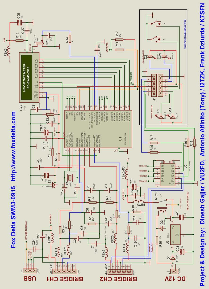
8 Schematic: SWM3-0915


9 Suitable HF Bride for SWM3-0915: Dual Scale HF Bridge: (Not part of this kit) Dual Scale HF Bridge has two scaling relays under CPU control. Basic procedure would be to adjust bridge with first set of presets for Lower range and then, adjust HIGH range using second set of presets. Relays used in this project are OEN 5V DC and has 2CO contacts. Bridge will work from 100W to over a KW Dual Scale Bridge Schematic: Please visit Bridge section for details on other available HF/VHF Bridges
10 SWM Complete Kit Parts List: Qtty Part ID Part Details 1 U1 PIC18F4550 Pre-Programmed DIP40 1 U2 ULN2803A DIP18 1 Q1 IRFD110 1 Z1 LM V 2 J4, 3 D9 Male R/A PCB Connector 1 J1 DC12V PCB Connector 1 J2 USB PCB Connector 2 LED Dual LED Common Anode (LED-KB) 2 SW1/2 12MM Push Buttons (LED-KB) 1 SWM3-KB-PCB Double Sided PTH PCB LED-KB-0915-A 1 SWM3-PCB Double Sided PTH PCB SWM Pair 16PIN SIL Male and Ribbon for LCD (2X8) 1 Pair 8PIN SIL Male and Ribbon for Keyboard 1 LCD 2x16 LCD with Backlight 1 RLY OEN42 or Similar 12V mini Relay 1CO 1 P1 10K Preset 1 X1 20MHZ Crystal in HC49U 1 U DIP IC Socket 1 40DIP IC Socket 4 RFC uH 6 FBX1-6 FB Inductors 1 D1 1N D2 1N Set Nuts / Bolts for LCD and KB Mounting 1 Case Free Powder Coated Metal Case All Resistors ¼ W 5% 8 47K R1, 2, 3, 4, 7, 8, 9, K R14, 15, 16, 17, 18, 3 10K R5, 11, 12, 1 3.3K R R13 Capacitors 7 1uf Tantalum/35V C12, 15, 9, 23, 25, 28, pf C17, 16 Ceramic uf Ploy C uf Poly C1, 7, 8, 10, 13, 18, 22, 24, 26, uF Poly C6, 5, 4, 2, 3, 11, 14, 19, 20, PIC18F4550 is supplied pre-programmed.
11 Kit Assembly: Kits are specially designed for radio amateurs with necessary expertise in understanding SWR, RF power measurement etc A dummy load and a Variable RF power source (Trx) will complete the alignment requirements. Do not buy this kit if you do not know what is an RF Bridge or if you do not understand what SWR means!! For those who do not have time to build kits, Assembled SWR Meters in a metal case (Powder Coated) are available at small extra charge or free for Senior Radio Amateurs. Although we have made few kits for sales, the basic concept of this project is to make available complete details on hardware and firmware/software. We expect that radio amateurs build this project on their own, using components from their own ham shack!! Following files are available for Homebrewers: 1. This info doc 2. CPU Schematic and parts list 3. Schematic and parts list for all four types of bridges 4. A Free PC Program by Tony / I2TZK 5. PIC Firmware by Tony /I2TZK for PIC18F Microchip PIC18 USB Boot loader for future updates Also do not forget to refer calibration procedure detailed on Bridge web pages by Frank / K7SFN SWM is the latest revision of our last SWM3 project. Revision was done keeping in view good response )and demand for more kits) received from radio amateurs interested in having a Simple and Good quality LCD SWR meter for their station at an affordable cost 73s Dinesh Gajjar / VU2FD Antonio Alfinito / I2TZK Frank Dzuirda / K7SFN 12 h September 2015 For more details, please visit Project Page:
AAZ-0914A USB, Blue tooth and Graphic CPU 50MHZ Antenna Analyzer
 Fox Delta Amateur Radio Projects & Kits FD- AAZ-0914A AAZ-0914A USB, Blue tooth and Graphic CPU 50MHZ Antenna Analyzer AAZ- 0914A KIT: USB Standalone, Blue tooth standalone and Graphic CPU capable 50MHZ*
3-60MHZ HF PIC18F2550 USB
 Fox Delta Amateur Radio Projects & Kits FD- AAZ-0217A Project Tech Info Doc: 3-60MHZ HF PIC18F2550 USB Antenna Analyzer AAZ- 0217A KIT: 3-60MHZ USB Antenna Analyzer Si5351 Assembly: M1 Kits are supplied
Mini-TNC Rev 0711 is designed exclusively to work as an APRS TNC.
 Fox Delta Amateur Radio Projects & Kits Mini-TNC Technical Details and Schematic: Mini-TNC - A 1200-Baud Packet TNC Rev. 0711 Completed Mini-TNC: Mini-TNC Rev 0711 is designed exclusively to work as an
FoxView: An APRS Stand-Alone LCD Viewer using PIC16F628A & MX614
 Fox Delta Amateur Radio Projects & Kits FD FoxView FoxView: An APRS Stand-Alone LCD Viewer using PIC16F628A & MX614 Completed FoxView: APRS activities have changed the very basic concept of amateur radio.
AAZ 0914A SWR Analyzer -Steps for a quick test
 FOX DELTA Amateur Radio Projects & Kits AAZ 0914A SWR Analyzer -Steps for a quick test Step What to do Expected result What to do if test fails Component tested 1 Visual inspection Carefully looking at
C S Technology Ltd. cstech.co.uk. DTMF display 32 kit with 2 line x 16 LCD display
 C S Technology Ltd cstech.co.uk DTMF display 32 kit with 2 line x 16 LCD display Our DTMF display can display up to 32 characters (16 per line). The display can be cleared by a button (not supplied) or
Transcendent Frequency Counter
 Transcendent Frequency Counter with blue 2 x 16 LCD display This manual will guide you how to assemble, test and operate this frequency counter KIT. Features: The transcendent counter has two input channels
Shack Clock kit. U3S Rev 2 PCB 1. Introduction
 Shack Clock kit U3S Rev 2 PCB 1. Introduction Thank you for purchasing the QRP Labs Shack Clock kit. This clock uses the Ultimate3S QRSS/WSPR kit hardware, but a different firmware version. It can be used
Storage Card Interface Kit
 Storage Card Interface Kit for MultiMediaCards(MMC) and Secure Digital Cards (SD) MMSD3K The MMSD3K is complete development kit interfaced to a SD or MMC card. This board ideal for projects that involve
Sierra Radio Systems. HamStack. Project Board Reference Manual V1.0
 Sierra Radio Systems HamStack Project Board Reference Manual V1.0 Welcome HamStack Project Board Reference Manual Revision 1.0.3 2011 George Zafiropoulos, KJ6VU and John Best, KJ6K This guide provides
Sierra Radio Systems. Digital Compass. Reference Manual. Version 1.0
 Sierra Radio Systems Digital Compass Reference Manual Version 1.0 Contents Digital compass board RS485 power injector For more information, go to the Sierra Radio Systems web site at www.sierraradio.net
QRPGuys Digital Dial/Frequency Counter
 QRPGuys Digital Dial/Frequency Counter First, familiarize yourself with the parts and check for all the components. If a part is missing, please contact us and we will send one. You must use qrpguys.parts@gmail.com
SWR ANALYZER. Wireless connecting SWRA unit to PC. September, SWR Analyzer by Tony, i2tzk Sept
 SWR ANALYZER Wireless connecting SWRA unit to PC September, 2013 SWR Analyzer by Tony, i2tzk Sept. 2013 1 1. Project description...3 2. Hardware and Software requirements...4 3. Getting started...5 3.1
Post Tenebras Lab. Written By: Post Tenebras Lab
 Post Tenebras Lab PTL-ino is an Arduino comptaible board, made entirely out of through-hole components. It is a perfect project to learn how to solder and start getting into the world of micro controllers.
Shack Clock kit PCB Revision: QCU Rev 1 or QCU Rev 3
 1. Introduction Shack Clock kit PCB Revision: QCU Rev 1 or QCU Rev 3 Thank you for purchasing this QRP Labs Shack Clock kit. The kit uses the same PCB and bag of components as some other QRP Labs kits.
MeterBuilder MB-1 PROGRAMMABLE RF POWER METER. CIRCUIT DESCRIPTION Version 1.01 June 2011
 MeterBuilder MB-1 PROGRAMMABLE RF POWER METER CIRCUIT DESCRIPTION Version 1.01 June 2011 Patent and Copyright Notices Patent Applied For Copyright Material in this document copyrighted 2011 FullWave, LLC.
Rapid40i PIC Prototyping PCB User Manual
 Description This is a PCB designed to facilitate the rapid prototyping of a device based on a 40 pin Microchip PIC microcontroller. To allow users to focus on their application, we take care of key housekeeping
Rapid28iXL PIC Prototyping PCB User Manual
 Description Features This is a PCB designed to facilitate the rapid prototyping of a device based on a 28 pin Microchip PIC microcontroller. To allow users to focus on their application, we take care of
Rapid40iXL PIC Prototyping PCB User Manual
 Description This is a PCB designed to facilitate the rapid prototyping of a device based on a 40 pin Microchip PIC microcontroller. To allow users to focus on their application, we take care of key housekeeping
Storage Card Interface Kit
 Storage Card Interface Kit for MultiMediaCards(MMC) and Secure Digital Cards (SD) MMSD3F The MMSD3K is complete development kit interfaced to a SD or MMC card. This board ideal for projects that involve
ES-562/564U COMBINATION CLOCK/TIMER
 142 SIERRA ST., EL SEGUNDO, CA 90245 USA (310)322-2136 FAX (310)322-8127 www.ese-web.com ES-562/564U COMBINATION CLOCK/TIMER OPERATION AND MAINTENANCE MANUAL The ES-562U/564U is a combination six digit
GLiPIC Ver C Assembly manual Ver 1.0
 GLiPIC Ver C Assembly manual Ver 1.0 Last Rev 1.1 Oct 30, 2001 Author: Ranjit Diol Disclaimer and Terms of Agreement As with any kit, only the individual parts supplied are guaranteed against defects and
Assembly Instructions (8/14/2014) Your kit should contain the following items. If you find a part missing, please contact NeoLoch for a replacement.
 Your kit should contain the following items. If you find a part missing, please contact NeoLoch for a replacement.") NeoLoch NLT-28P-LCD-5S Assembly Instructions (8/14/2014) Your kit should contain the following items. If you find a part missing, please contact NeoLoch for a replacement. Kit contents: 1 Printed circuit
NeoLoch NLT-28P-LCD-5S Assembly Instructions (8/14/2014) Your kit should contain the following items. If you find a part missing, please contact NeoLoch for a replacement. Kit contents: 1 Printed circuit
Exclusive 2.5 GHz Frequency Counter
 Exclusive 2.5 GHz Frequency Counter with blue 2 x 16 LCD display This manual will guide you how to assemble, test and tune this frequency counter KIT. Features: Frequency range from 5 MHz to 2.5GHz Factory
SWR ANALYZER. Measuring with an ANDROID device. GALAXY Mini I5800. SWRA & BT adapter. Samsung GT-3110 Tablet 2 7. September 2013
 SWR ANALYZER Measuring with an ANDROID device GALAXY Mini I5800 SWRA & BT adapter Samsung GT-3110 Tablet 2 7 September 2013 SWR Android v1.03 by I2TZK 1 INDEX 1. Project description 3 2. Getting started
Schematic Diagram: R2,R3,R4,R7 are ¼ Watt; R5,R6 are 220 Ohm ½ Watt (or two 470 Ohm ¼ Watt in parallel)
") Nano DDS VFO Rev_2 Assembly Manual Farrukh Zia, K2ZIA, 2016_0130 Featured in ARRL QST March 2016 Issue Nano DDS VFO is a modification of the original VFO design in Arduino Projects for Amateur Radio by
Nano DDS VFO Rev_2 Assembly Manual Farrukh Zia, K2ZIA, 2016_0130 Featured in ARRL QST March 2016 Issue Nano DDS VFO is a modification of the original VFO design in Arduino Projects for Amateur Radio by
SRI-02 Speech Recognition Interface
 SRI-02 Speech Recognition Interface Data & Construction Booklet The Speech Recognition Interface SRI-02 allows one to use the SR-07 Speech Recognition Circuit to create speech controlled electrical devices.
SBC45EC. Single board computer for 44 pin PLCC PICs
 Single board computer for 44 pin PLCC PICs Table of Contents 1 Introduction...3 2 Features...4 3 Expansion Connectors...5 3.1 Frontend Connectors...5 3.1.1 Connecting IDC connectors to the Frontend Connector...5
QRPometer Assembly Manual Copyright 2012 David Cripe NM0S The 4 State QRP Group. Introduction
 QRPometer Assembly Manual Copyright 2012 David Cripe NM0S The 4 State QRP Group Introduction Thank you for purchasing a QRPometer. We hope you will enjoy building it and and find it a useful addition to
PICado Alpha Development Board V1.0
 V1.0 Bluetooth Transceiver Module HC-05 Four onboard FET power output stage 34 freely assignable I/O pins ICSP interface 2015 Jan Ritschard, All rights reserved. V1.0 Table of Contents 1. Introduction...
Modtronix Engineering Modular Electronic Solutions SBC28DC. Single board computer for 28 pin DIP PICs
 Modtronix Engineering Modular Electronic Solutions Single board computer for 28 pin DIP PICs Table of Contents 1 Introduction...2 2 Features...4 3 Expansion Connectors...5 3.1 Daughter Board Connectors...5
AKKON USB CONTROLLER BOARD
 TN002 AKKON USB CONTROLLER BOARD USB Microcontroller board with the PIC18F4550 * Datasheet Authors: Gerhard Burger Version: 1.0 Last update: 20.01.2006 File: Attachments: no attachments Table of versions
SWR ANALYZER. Optional Add-On User Guide. January, SWRA Optional Add-On v1.00 by Tony, i2tzk Page. 1
 SWR ANALYZER Optional Add-On User Guide January, 2015 SWRA Optional Add-On v1.00 by Tony, i2tzk Page. 1 Index 1 Optional add-on... 3 2 FD-AAZ-0914-BT2 Bluetooth module... 4 2.1 Testing the Bluetooth Adapter...
Ultimate LPF kit: Relay-switched LPF kit
 Ultimate LPF kit: Relay-switched LPF kit PCB Revision 4 1. Introduction Thank you for purchasing the QRP Labs relay-switched low-pass filter (LPF) kit. This kit is designed to complement the Ultimate3
Cumbria Designs T-1. C-1 Controller. User Manual
 Cumbria Designs T-1 C-1 Controller User Manual CONTENTS 1 INTRODUCTION 2 2 CIRCUIT DESCRIPTION 2 3 ASSEMBLY 3 4 CONNECTIONS AND CONFIGURATION 4 5 TESTING 6 Appendix A C-1 Circuit Diagram and PCB Component
PIC 28 Pin Board Documentation. Update Version 5.0
 PIC 28 Pin Board Documentation Update 2009.10 Version 5.0 Table of Contents PIC 28 Pin Board Documentation... 1 Table of Contents... 2 Introduction... 3 Circuit Schematic... 4 The following is the Circuit
AAØZZ Si570 Daughtercard and PIC Software
 AAØZZ Si570 Daughtercard and PIC Software A Signal Generator for 10 to 157 MHz By Craig Johnson, AAØZZ AAØZZ@CBJOHN.COM www.cbjohn.com/aaøzz TABLE OF CONTENTS 1 Introduction... 2 2 Hardware Description...
Bolt 18F2550 System Hardware Manual
 1 Bolt 18F2550 System Hardware Manual Index : 1. Overview 2. Technical specifications 3. Definition of pins in 18F2550 4. Block diagram 5. FLASH memory Bootloader programmer 6. Digital ports 6.1 Leds and
H89-Z37 DOUBLE-DENSITY FLOPPY CONTROLLER
 H8-Z37 DOUBLE DENSITY FLOPPY CONTROLLER 2015 H89-Z37 DOUBLE-DENSITY FLOPPY CONTROLLER Norberto Collado norby@koyado.com 6/6/2015 Revision History and Disclaimer Revision History Revision Date Comments
[Note: Power adapter is not included in the kits. Users need to prepare a 9 12 V ( >300mA capacity ) DC power supply]
![[Note: Power adapter is not included in the kits. Users need to prepare a 9 12 V ( >300mA capacity ) DC power supply]](/thumbs/76/74094055.jpg "[Note: Power adapter is not included in the kits. Users need to prepare a 9 12 V ( >300mA capacity ) DC power supply]") 062 LCD Oscilloscope Assembly Notes Applicable Models: 06203KP, 06204KP DN062-18v02 Important Notes 1. Some components shown in the schematic and PCB layout are for options or adjustments. They do not
062 LCD Oscilloscope Assembly Notes Applicable Models: 06203KP, 06204KP DN062-18v02 Important Notes 1. Some components shown in the schematic and PCB layout are for options or adjustments. They do not
Chip Level Repair In Laptop / Notebook / Ultra book
 Chip Level Repair In Laptop / Notebook / Ultra book Start from Basic full Electronics: Atomic Structure, Current, AC,DC, Examples of AC,DC, Waves, Difference Between AC and DC Difference Between Electronics
SK40C ENHANCED 40 PINS PIC START-UP KIT. User s Manual V1.3. March 2012
 SK40C ENHANCED 40 PINS PIC START-UP KIT User s Manual V1.3 March 2012 Information contained in this publication regarding device applications and the like is intended through suggestion only and may be
Ocean Controls KT-5193 Modbus Programmable Stepper Motor Controller
 Ocean Controls KT-5193 Modbus Programmable Stepper Motor Controller The Ocean Controls Modbus Programmable Stepper Motor Controller is a four axis multifunction programmable stepper motor controller which
SBC65EC. Ethernet enabled Single Board Computer
 Ethernet enabled Single Board Computer Table of Contents 1 Introduction...2 2 Features...3 3 Daughter Board Connectors...4 3.1 As a Daughter Board...5 3.2 Expansion boards...5 4 Interfaces...5 4.1 Ethernet...5
Images Scientific OWI Robotic Arm Interface Kit (PC serial) Article
 Article") Images Scientific OWI Robotic Arm Interface Kit (PC serial) Article Images Company Robotic Arm PC Interface allows real time computer control and an interactive script writer/player for programming and
Images Scientific OWI Robotic Arm Interface Kit (PC serial) Article Images Company Robotic Arm PC Interface allows real time computer control and an interactive script writer/player for programming and
QCU: QRP Labs Control Unit PCB Revision 1
 QCU: QRP Labs Control Unit PCB Revision 1 1. Introduction Thank you for purchasing this QRP Labs kit. The QRP Labs kit range is modular. This kit is used as the basis of several other kits. Not all of
VFO/Signal Generator kit PCB Revision QCU Rev 1 or QCU Rev 3
 1. Introduction VFO/Signal Generator kit PCB Revision QCU Rev 1 or QCU Rev 3 Thank you for purchasing this QRP Labs kit. The QRP Labs kit range is modular. The kit uses the same PCB and bag of components
Insert the male, 90 angled, 2x10 connectors into the corresponding 2x10 sockets and put them in place, flat under the PCB. Solder.
 MC624 Assembly guide Safety warning The kits are main powered and use potentially lethal voltages. Under no circumstance should someone undertake the realisation of a kit unless he has full knowledge about
Building RoboPIC 18F4550
 RoboPIC 8F4550 Copyright 206 William Henning Building RoboPIC 8F4550 Copyright 206 William Henning RoboPIC 8F4550 build manual v0.90 The most up to date documentation will always be available at: http://www.mikronauts.com/robot-controllers/robopic-8f4550/
4.0 Blue LED DCF77 Clock documentation
 4.0 Blue LED DCF77 Clock documentation 1. LED Clock Main Board PCB mounting: Mount and solder the eight wire bridges. Mount and solder resistors R16, R18, R20, R22. Mount and solder capacitors C1 C3 (pitch
Pacific Antenna Easy TR Switch Kit
 Pacific Antenna Easy TR Switch Kit Kit Description The Easy TR Switch is an RF sensing circuit with a double pole double throw relay that can be used to automatically switch an antenna between a separate
Desktop housing AZ/EL Kit V1.2 for ERC-M Instructions. Instructions
 Instructions Desktop housing AZ/EL it V1.2 for ERC-M Instructions Congratulations for buying your Desktop housing AZ/EL for ERC-M. This document will guide you through the needed steps for assembly of
SBC44EC. Single board computer for 44 pin PLCC PICs
 Single board computer for 44 pin PLCC PICs Table of Contents 1 Introduction...2 2 Features...3 3 Expansion Connectors...4 3.1 Frontend Connectors...4 3.1.1 Connecting IDC connectors to the Frontend Connector...5
CP5176 Assembly guide. Soldering. CP5176 Assembly guide Main PCB PCB split. Document revision 2.1 Last modification : 12/11/17
 CP5176 Assembly guide Safety warning The kits are main powered and use potentially lethal voltages. Under no circumstance should someone undertake the realisation of a kit unless he has full knowledge
SRD- Switching Regulator Step-down regulator. Switch-mode Step-down Regulator
 Switch-mode Step-down The SRD power converter is a high frequency, switch-mode, step-down regulator for applications requiring stable power. The compact and efficient design requires little heatsinking
KEYLITE. Specifications: The Keylite keys your rig with paddles or an IBM compatible Keyboard. Power Requirements: 9V-14V
 KEYLITE The Keylite keys your rig with paddles or an IBM compatible Keyboard. Specifications: Power Requirements: 9V-14V Maximum current draw: Less than 20ma plus Keyboard. Keyboard input: Standard IBM
ES-362U PRESETTABLE MASTER TIMER
 142 SIERRA ST., EL SEGUNDO, CA 90245 USA (310)322-2136 FAX (310)322-8127 www.ese-web.com ES-362U PRESETTABLE MASTER TIMER OPERATION AND MAINTENANCE MANUAL The ES-362U is a four digit, presettable 100 minute
DEV-1 HamStack Development Board
 Sierra Radio Systems DEV-1 HamStack Development Board Reference Manual Version 1.0 Contents Introduction Hardware Compiler overview Program structure Code examples Sample projects For more information,
Hardware Manual - SM2251 Evaluation Kit Board
 Hardware Manual - SM2251 Evaluation Kit Board Release 1.0.0 SonMicro Elektronik Oct 08, 2017 CONTENTS 1 INTRODUCTION 1 1.1 FEATURES............................................... 1 1.2 SUPPORTED MODULES.......................................
The FED PIC Flex 2 Development Boards
 The FED PIC Flex 2 Development Boards THE FED PIC Flex Development board offers a host for 28 or 40 pin devices and includes LED's, switches, transistor switches, USB interface, serial port, support circuitry,
Infinity Project. an additional memory for GLCD where to store programs. July Infinity Project. Additional memory for GLCD by Tony, i2tzk Pag.
 Infinity Project an additional memory for GLCD where to store programs July 2014 Infinity Project. Additional memory for GLCD by Tony, i2tzk Pag. 1 INDEX 1. Project description 3 2. Getting started 6 2.1
BMC24. MIDI TO GATE CONVERTER DOCUMENTATION. This documentation is for use with the "Euro Style" bottom board.
 BMC24. MIDI TO GATE CONVERTER DOCUMENTATION. This documentation is for use with the "Euro Style" bottom board. A. USING THE MIDI TO GATE CONVERTER B. PARTS LIST C. BUILDING INSTRUCTIONS D. SCHEMATICS Revision.
ON4AKH Antenna Rotator controller Version 1.0
 ON4AKH Antenna Rotator controller Version 1.0 1. Some construction tips The project consists out of 3 boards. The 1 st board is the main board containing the PIC micro controller and the H-bridge components
Ultimate3S: Multi-mode QRSS/WSPR transmitter kit. PCB Revision: QCU Rev 1
 Ultimate3S: Multi-mode QRSS/WSPR transmitter kit 1. Introduction PCB Revision: QCU Rev 1 Thank you for purchasing this QRP Labs kit. You will also plug in other modules. You need to download assembly instructions
Construction Construction Instructions
 Semi-Virtual Diskette SVD Construction Construction Instructions PCB version 2.0 September 2004 Eric J. Rothfus Table of Contents Table of Contents... i Parts List...1 Construction Overview...5 PCB Construction...
DMX512-4 Channel PWM Driver Board #805
 DMX512-4 Channel PWM Driver Board #805 Overview The 4-channel PWM driver board provides four open drain (collector) type outputs that can be directly controlled from a DMX512 network. The four channels
DEV16T. LCD Daughter board
 LCD Daughter board Table of Contents 1 Introduction...2 2 Features...3 3 Expansion Connectors...4 3.1 Daughter Board Connectors...4 4 LCD Display...5 5 Input Buttons S1 to S4...5 6 Buzzer...5 7 Connector
Keywords Digital IC tester, Microcontroller AT89S52
 Volume 6, Issue 1, January 2016 ISSN: 2277 128X International Journal of Advanced Research in Computer Science and Software Engineering Research Paper Available online at: www.ijarcsse.com Digital Integrated
KPIC-0818P (V050919) Devices Included in this Data sheet: KPIC-0818P
 Devices Included in this Data sheet: KPIC-0818P") Devices Included in this Data sheet: KPIC-0818P Features: Carefully designed prototyping area Accepts 8 pin PIC12 series micro-controllers Accepts 14 and 18 Pin PIC16 series Accepts some 8,14 and 18 pin
Devices Included in this Data sheet: KPIC-0818P Features: Carefully designed prototyping area Accepts 8 pin PIC12 series micro-controllers Accepts 14 and 18 Pin PIC16 series Accepts some 8,14 and 18 pin
QUASAR PROJECT KIT # ATMEL AVR PROGRAMMER
 This kit is a simple but powerful programmer for the Atmel AT90Sxxxx ( AVR ) family of microcontrollers. The Atmel AVR devices are a low-power CMOS 8-bit microcontroller using a RISC architecture. By executing
DIY Line Tracking Smart Car with AT89C2051
 DIY Line Tracking Smart Car with AT89C2051 1. Introduction: A DIY Smart Car design involves mechanical structure, electronic based sensor principle, automatic control, and even knowledge of microcontroller
WORLD LEADING PRODUCTS FOR LASER SCIENTISTS AND ENGINEERS
 2 Output TEC Controller, 128 Watts Each Output, Optimized for Laser & Non-Linear Crystal Temperature Control High Stability Temperature Controller for Laser Diodes and Crystals 2 x ±16.00 Volt, ±8.00 Amp
MICRO-TRAK 300 MANUAL VER 1.4
 MICRO-TRAK 300 MANUAL VER 1.4 The Micro-Trak 300 Version 1.4 is a miniature APRS (Automatic Position Reporting System) transmitter operating on the North American APRS frequency standard of 144.390 MHz.
Pickup Gaussmeter v.3.0
 Pickup Gaussmeter v.3.0 Features: Range +/- 5600 gauss (with AD22151 sensor) or +/- 1700 Gauss (with A1302 sensor) PCB for main unit and for a double-sensor (A1302-AD22151) double-face probe Normal, peak-hold
University of Florida EEL 4744 Drs. Eric M. Schwartz, Karl Gugel & Tao Li Department of Electrical and Computer Engineering
 Page 1/9 Revision 1 OBJECTIVES In this document you will learn how to solder and to debug a board as you are building it. REQUIRED MATERIALS Website documents o UF 68HC12 Development Board Manual (board
Thursday, September 15, electronic components
 electronic components a desktop computer relatively complex inside: screen (CRT) disk drive backup battery power supply connectors for: keyboard printer n more! Thursday, September 15, 2011 integrated
Display Real Time Clock (RTC) On LCD. Version 1.2. Aug Cytron Technologies Sdn. Bhd.
 On LCD. Version 1.2. Aug Cytron Technologies Sdn. Bhd.") Display Real Time Clock (RTC) On LCD PR12 Version 1.2 Aug 2008 Cytron Technologies Sdn. Bhd. Information contained in this publication regarding device applications and the like is intended through suggestion
Display Real Time Clock (RTC) On LCD PR12 Version 1.2 Aug 2008 Cytron Technologies Sdn. Bhd. Information contained in this publication regarding device applications and the like is intended through suggestion
Bill of Materials D RF INTERFACE CCA G. Assembly No.: Description: Revision:
 D161020 RF INTERFACE CCA Designator Item Part Number Qty UOM Description Engineering Description TB2-TB5 19B1547-002 4 EA CONNECTOR, HEADER 2P PC HEADER J4 19B1547-003 1 EA CONNECTOR, HEADER 3P PC HEADER
Sprinkler Controller Assembly Manual
 Sprinkler Controller Assembly Manual V1.0 Doug Jackson VK1ZDJ September 2010 Licence The Sprinkler Controller Design, PCB layout, Manual, and Firmware is Copyright 2010, by Douglas Jackson, VK1ZDJ. This
MAIN PCB (The small one)
") THANKS FOR CHOOSING ONE OF OUR KITS! This manual has been written taking into account the common issues that we often find people experience in our workshops. The order in which the components are placed
THANKS FOR CHOOSING ONE OF OUR KITS! This manual has been written taking into account the common issues that we often find people experience in our workshops. The order in which the components are placed
Sierra Radio Systems. Station Controller. User Guide. Version 1.1
 Sierra Radio Systems User Guide Station Controller Version 1.1 Welcome HamStack GPIO Board Reference Manual Revision 1.0 2011 George Zafiropoulos, KJ6VU and John Best, KJ6K This guide provides a broad
KIT 134. INTRODUCTION TO LCD S
 The aim of this kit is to show how to use a 16x2 alphanumeric Liquid Crystal Display (LCD) with a PC. First we show how to connect it to the parallel port and echo and handle keyboard input. Then we show
solutions for teaching and learning
 RKP18Motor Component List and Instructions PCB layout Constructed PCB Schematic Diagram RKP18Motor Project PCB Page 1 Description The RKP18Motor project PCB has been designed to use PIC microcontrollers
AVR-M Rev 5 ASSEMBLY
 AVR-M Rev 5 ASSEMBLY The AVR_M is a very compact self contained Atmel AVR mcu controller board. It includes an onboard serial programmer (via PC com port), an I2C eeprom and can use a Mega163, Mega16 or
Installation/assembly manual for DCC/Power shield
 Installation/assembly manual for DCC/Power shield The DCC circuit consists of the following components: R1/R6 R2/R3 R4/R5 D1 C2 2 kω resistor ½ Watt (colour code Red/Black/Black/Brown/Brown) 10 kω resistor
SharpSky Focuser Construction. SharpSky Focuser. Construction Document V st December 2012 Dave Trewren 1
 SharpSky Focuser Construction Document V0.12 1st December 2012 Dave Trewren 1 Contents 1 General... 3 1.1 Change Record... 3 1.2 References... 3 2 Introduction... 5 3 SharpSky driver installation... 5
LED Knight Rider. Yanbu College of Applied Technology. Project Description
 LED Knight Rider Yanbu College of Applied Technology Project Description This simple circuit functions as a 12 LED chaser. A single illuminated LED 'walks' left and right in a repeating sequence, similar
K8099 NIXIE CLOCK. * optional enclosure TKOK19 (black) - TKOK17 (white) ** optional plexiglass enlcosure B8099 ILLUSTRATED ASSEMBLY MANUAL
 - TKOK17 (white) ** optional plexiglass enlcosure B8099 ILLUSTRATED ASSEMBLY MANUAL") Total solder points: 230 + 74 Difficulty level: beginner 1 2 3 4 5 advanced NIXIE CLOCK K8099 ** * A unique combination of both vintage and modern electronics ILLUSTRATED ASSEMBLY MANUAL H8099IP-1 * optional
Total solder points: 230 + 74 Difficulty level: beginner 1 2 3 4 5 advanced NIXIE CLOCK K8099 ** * A unique combination of both vintage and modern electronics ILLUSTRATED ASSEMBLY MANUAL H8099IP-1 * optional
Variable Power Supply Digital Control Circuit Diagram Using Lm317
 Variable Power Supply Digital Control Circuit Diagram Using Lm317 DIGITAL POWER SUPPLY USING LM317 A Major Project Report Submitted partial fulfillment of the requirement for the award of the Degree of
Electronic Lock CodeLock AVR 1 DIY electronic door lock
 Electronic Lock CodeLock AVR 1 DIY electronic door lock CodeLock AVR LCD CodeLock AVR electronic lock is realised with Atmel AVR micro-controller AT90S2313, ATtiny2313 or ATtiny45. 1 user code in the program
UNIVERSAL LCD CONTROL MODULE V4.0 Assembly and operating instructions
 PCS Electronics www.pcs-electronics.com info@pcs-electronics.com UNIVERSAL LCD CONTROL MODULE V4.0 Assembly and operating instructions Universal LCD control module is used to control all of our LCD-unit
SM010, Assembly Manual PCB Version 1.0
 180 SM010, Assembly Manual MATRIXARCHATE 16 8 IO SEQUENTIAL MATRIX SIGNAL ROUTER SM010 1 2 1 2 3 4 5 3 4 5 6 7 8 9 10 11 12 6 7 8 9 10 11 12 13 14 15 16 PROGRAM A B C D E F G H f1 f2 20.000 180 SSSR Labs
BUILDING YOUR KIT. For the Toadstool Mega328.
 BUILDING YOUR KIT For the Toadstool Mega328 www.crash-bang.com @crashbang_proto This work is licensed under a Creative Commons Attribution-ShareAlike 4.0 International License. Congratulations! You re
JUNEBUG PIC LABORATORY
 JUNEBUG PIC LABORATORY Assembly Instructions The Junebug PIC Lab Introduction Powered from your computers USB port the Junebug is everything you ll need in a small self contained portable PIC Laboratory
RFID: Read and Display V2010. Version 1.1. Sept Cytron Technologies Sdn. Bhd.
 PR8-B RFID: Read and Display V2010 Version 1.1 Sept 2010 Cytron Technologies Sdn. Bhd. Information contained in this publication regarding device applications and the like is intended through suggestion
Linux Kernel Hacking Free Course, 3rd edition. HWMPS: Hardware Monitor & Protection System
 Andrea Sarro University of Rome Tor Vergata HWMPS: Hardware Monitor & Protection System April 5, 2006 Outline of the talk Project overview Developement phases and practical issues Hardware platform Microcontroller
Sierra Radio Systems. Making a Keyer with the. HamStack. Project Platform
 Sierra Radio Systems Making a Keyer with the HamStack Project Platform Introduction The HamStack Project Board includes primary interface elements needed to make a high quality CW keyer. Using the LCD
GUIDE TO ASSEMBLY OF ERICA SYNTHS MIDI-CV MODULE
 GUIDE TO ASSEMBLY OF ERICA SYNTHS MIDI-CV MODULE If you are reading this, most probably, you are about to build Erica Synths DIY MIDI-CV module. This module is mm deep, skiff friendly, has solid mechanical
アナログ. A/500 FET Limiter PCB Overlay, Schematic and Bill of Materials mnats
 アナログ A/500 FET Limiter PCB Overlay, Schematic and Bill of Materials 2014 mnats LED1 LED2 Q1_ALT Q11_ALT R23 IC1 R55 R56 GR SIG +VR -VR -V IN VU SIG 0 ADJ Q6 ST LNK SW3 SW1 R21 R61 R4 R5 R7 Q1 R8 C2 C6
Web Site: Forums: forums.parallax.com Sales: Technical:
 Web Site: www.parallax.com Forums: forums.parallax.com Sales: sales@parallax.com Technical: support@parallax.com Office: (916) 624-8333 Fax: (916) 624-8003 Sales: (888) 512-1024 Tech Support: (888) 997-8267