Command and Control Tutorial
|
|
|
- Bennett Nash
- 5 years ago
- Views:
Transcription
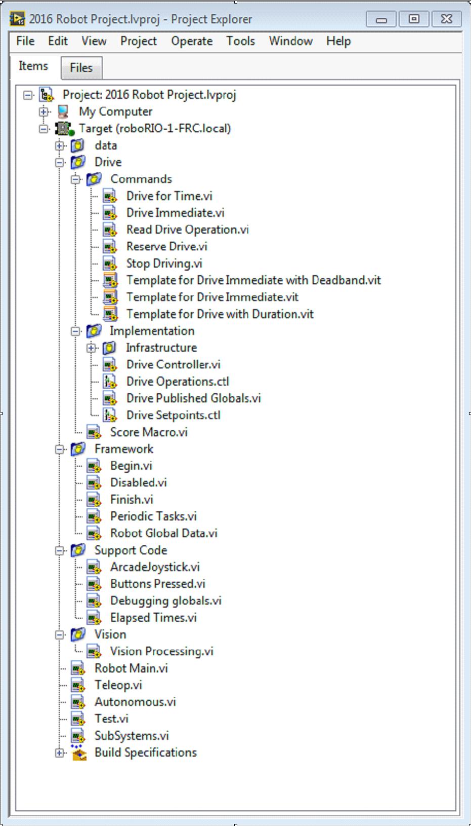
1 Command and Control Tutorial Introduction Command and Control is a new LabVIEW template added for the 2016 season which organizes robot code into commands and controllers for a collection of robot-specific subsystems. Each subsystem has an independent control loop or state machine running at the appropriate rate for the mechanism and high-level commands that update desired operations and set points. This makes it very easy for autonomous code to build synchronous sequences of commands. Meanwhile, TeleOp benefits because it can use the same commands without needing to wait for completion, allowing for easy cancellation and initiation of new commands according to the drive team input. Each subsystem has a panel displaying its sensor and control values over time, and command tracing to aid in debugging. What is Command and Control? Command and Control recognizes that FRC robots tend to be built up of relatively independent mechanisms such as Drive, Shooter, Arm, etc. Each of these is referred to as a subsystem and needs code that will coordinate the various sensors and actuators of the subsystem in order to complete requested commands, or actions, such as Close Gripper or Lower Arm. One of the key principles of this framework is that subsystems will each have an independent controller loop that is solely responsible for updating motors and other actuators. Code outside of the subsystem controller can issue commands which may change the robot s output, but should not directly change any outputs. The difference is very subtle but this means that outputs can only possibly be updated from one location in the project. This speeds up debugging a robot behaving unexpectedly by giving you the ability to look through a list of commands sent to the subsystem rather than searching your project for where an output may have been modified. It also becomes easier to add an additional sensor, change gearing, or disable a mechanism without needing to modify code outside of the controller. Game code, primarily consisting of Autonomous and TeleOp, will typically need to update set points and react to the state of certain mechanisms. For Autonomous, it is very common to define the robot s operation as a sequence of operations drive here, pick that up, carry it there, shoot it, etc. Commands can be wired sequentially with additional logic to quickly build complex routines. For teleop, the same commands can execute asynchronously, allowing the robot to always Page 1
2 process the latest driver inputs, and if implemented properly, new commands will interrupt, allowing the drive team to quickly respond to field conditions while also taking advantage of automated commands and command sequences. Why should I use Command and Control? Command and Control adds functionality to the existing LabVIEW project templates, allowing code to scale better with more sophisticated robots and robot code. Subsystems are used to abstract the details of the implementation, and game code is built from sequences of high level command VIs. The commands themselves are VIs that can update set points, perform numerical scaling/ mapping between engineering units and mechanism units, and offer synchronization options. If physical changes are made to the robot, such as changing a gearing ratio, changes can be made to just a few command Vis to reflect this change across the entire code base. I/O encapsulation makes for more predictable operation and quicker debugging when resource conflicts do occur. Because each command is a VI, you are able to single step through commands or use the built in Trace functionality to view a list of all commands sent to each subsystem.the framework uses asynchronous notification and consistent data propagation making it easy to program a sequence of commands or add in simple logic to determine the correct command to run. Part 1: Project Explorer The Project Explorer provides organization for all of the Vis and files you will use for your robot system. Below is a description of the major components in the Project Explorer to help with the expansion of our system. The most frequently used items have been bolded. Page 2
3 Page 3
4 My Computer the items that define operation on the computer that the project was loaded on. For a robot project, this is used as a simulation target and is populated with simulation files. Sim Support Files folder containing 3D CAD models and description files for the simulated robot. Robot Simulation Readme.html documents the PWM channels and robot info you will need in order to write robot code that matches the wiring of the simulated robot. Dependencies shows the files used by the simulated robot s code. This will populate when you designate the code for the simulated robot target. Build Specifications will contain the files that define how to build and deploy code for the simulated robot target. Target (roborio-team-frc.local) the items that define operation on the roborio located at (address). Drive subsystem implementation and commands for the robot drive base. This serves as a custom replacement for the WPILib RobotDrive VIs. Framework VIs used for robot code that is not part of a subsystem that are not used very often. Begin called once when robot code first starts. This is useful for initialization code that doesn t belong to a particular subsystem. Disabled called once for each disabled packet and can be used to debug sensors when you don t want the robot to move. Finish during development, this may be called when robot code finishes. Not called on abort or when power is turned off. Periodic Tasks a good place for ad hoc periodic loops for debugging or monitoring Robot Global Data useful for sharing robot information that doesn t belong to a subsystem. Page 4
5 Support Code debugging and code development aids. Vision subsystem and commands for the camera and image processing. Robot Main.vi Top level VI that you will run while developing code. Autonomous.vi VI that runs during autonomous period. Teleop.vi VI that is called for each TeleOp packet. Test.vi VI that runs when driver station is in test mode. SubSystems.vi VI that contains and starts all subsystems. Dependencies shows the files used by the robot code. Build Specifications used to build and run the code as a startup application once code works correctly. Page 5

6 Drive Subsystem Project Explorer Commands: This folder contains the command VIs that request the controller carry out an operation. It also contains templates for creating additional drive commands. Note: After creating a new command, you may need to edit Drive Setpoints.ctl to add or update fields that controller uses to define the new operation. You also need to go into the Drive Controller.vi and modify the case structure to add a case for every value. Implementation: These are the VIs and Controls used to build the subsystem. Infrastructure VIs Drive Check for New Command: It is called each iteration of the controller loop. It checks for new commands, updates timing data, and upon completion notifies a waiting command. Drive Command Helper.vi: Commands call this VI to notify the controller that a new command has been issued. Page 6
7 Drive Controller Initialization.vi: It allocates the notifier and combines the timing, default command, and other information into a single data wire. Drive Controller.vi: This VI contains the control/state machine loop. The panel may also contain displays useful for debugging. Drive Operation.ctl: This typedef defines the operational modes of the controller. Many commands can share an operation. Drive Setpoint.ctl: It contains the data fields used by all operating modes of the Drive subsystem. Drive Published Globals.vi: A useful place for publishing global information about the drive subsystem. Part 2: Initializing the Drive Subsystem There are green comments on the controller s block diagram that point out key areas that you will want to know how to edit. The area to the left of the control loop will execute once when the subsystem starts up. This is where you will typically allocate and initialize all I/O and state data. You may publish the I/O refnums, or you may register them for Test Mode Only to keep them private so that other code cannot update motors without using a command. Page 7


8 Note: Initializing the resources for each subsystem in their respective Controller.vi rather than in Begin.vi improves I/O encapsulation, reducing potential resource conflicts and simplifies debugging. Page 8

9 Part of the initialization is to select the default operation and set point values when no other operation is being processed. Inside the control loop is a case statement where operations are actually implemented. Set point values, iteration delay, iteration count, and sensors can all have influence on how the subsystem operates. This case structure has a value for each operation state of the subsystem. Page 9

10 Each iteration of the controller loop will optionally update the Trace VI. The framework already incorporates the subsystem name, operation, and description, and you may find it helpful to format additional set point values into the trace information. Open the Trace VI and click Enable while the robot code is running to current setpoints and commands sent to each subsystem. The primary goal of the controller is to update actuators for the subsystem. This can occur within the case structure, but many times, it is beneficial to do it downstream of the structure to ensure that values are always updated with the correct value and in only one location in the code. Page 10
11 Part 3: Drive Subsystem Shipped Commands There are 3 shipped example commands for each new subsystem: Drive For Time.vi This VI sets the motors to run for a given number of seconds. It optionally synchronizes with the completion of the command. The Drive for Time case will operate the motors at the set point until the timer elapses or a new command is issued. If the motors have the safety timeout enabled, it is necessary to update the motors at least once every 100ms. This is why the code waits for the smaller of the remaining time and 50ms. Page 11
12 Drive Immediate.vi Gets the desired left and right speeds for the motors and will set the motors immediately to those set points. The Immediate case updates the motors to the set point defined by the command. The command is not considered finished since you want the motors to maintain this value until a new command comes in or until a timeout value. The timeout is useful anytime a command includes a dead band. Small values will not be requested if smaller than the dead band, and will result in growling or creeping unless the command times out. Page 12

13 Stop Driving.vi Zero the drive motors, making the robot stationary. The Reserve command turns off the motors and waits for a new command. When used with a named command sequence, reserve identifies that the drive subsystem is part of a sequence, even if not currently moving the robot. This helps to arbitrate subsystem resource between simultaneously running commands. Page 13
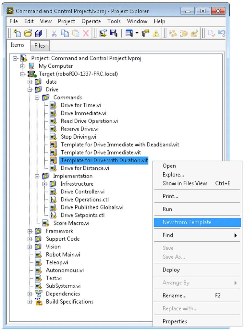
14 Part 4: Creating New Commands The Command and Control framework allows users to easily create new commands for a subsystem. To Create a new command open the subsystem folder/commands In the project explorer window, choose one of the VI Templates to use as the starting point of your new command, right click, and select New From Template. Immediate: This VI notifies the subsystem about the new setpoint. Immediate with deadband: This VI compares the input value to the deadband and optionally notifies the subsystem about the new setpoint. This is very useful when joystick continuous values are being used. With duration: This VI notifies the subsystem to perform this command for the given duration, and then return to the default state. Synchronization determines whether this VI Starts the operation and returns immediately, or waits for the operation to complete. The first option is commonly used for TeleOp, and the second for Autonomous sequencing. In this example we will add the new command Drive for Distance. Page 14
15 Page 15
16 First, save the new VI with a descriptive name such as Drive for Distance. Next, determine whether the new command needs a new value added the Drive Operations enum typedef. The initial project code already has an enum value of Drive for Distance, but the following image shows how you would add one if needed. Page 16

17 If a command needs additional information to execute, add it to the setpoints control. By default, the Drive subsystem has fields for the Left Setpoint, Right Setpoint, and Duration along with the Page 17

18 operation to be executed. The Drive for Distance command could reuse Duration as distance, but let s go ahead and add a numeric control to the Drive Setpoints.ctl called Distance (feet). Once that we have all of the fields needed to specify our command, we can modify the newly created Drive for Distance.vi. As shown below, select Drive for Distance from the enum s drop down menu and add a VI parameters to specify distance, speeds, etc. If the units do not match, the command VI is a great place to map between units. Page 18
19 Next, add code to the Drive Controller to define what happens when the Drive for Distance command executes. Right click on the Case Structure and Duplicate or Add Case for Every Value. This will create a new Drive for Distance case. Page 19


20 In order to access new setpoint fields, grow the Access Cmd setpoints unbundle node. Open your encoder(s) on the outside, to the left of the loop. In the new diagram of the case structure, we added a call to reset the encoder on the first loop iteration and read it otherwise. There is also some simple code that compares encoder values and updates the motor power. If new controls are added to the setpoints cluster, you should also consider adding them to the Trace. The necessary changes are shown in the image below. Part 5: Creating a Subsystem In order to create a new subsystem, right click on the roborio target and select New» Subsystem. In the pop up dialog box, enter the name of the subsystem, list the operational modes, and specify the color of the icon. Page 20

21 When you click OK, the subsystem folder will be generated and added to the project disk folder and tree. It will contain a base implementation of the VIs and controls that make up a subsystem. A call to the new controller will be inserted into the Subsystems VI. The controller VI will open, ready for you to add I/O and implement state machine or control code. Generated VI icons will use the color and name provided in the dialog. The generated code will use typedefs for set point fields and operations. Page 21


22 Below is the block diagram of the newly created subsystem. This code will be generated automatically when you create the subsystem. Page 22
FRC LABVIEW PROGRAMMING
 FRC LABVIEW PROGRAMMING Last Updated: 01-06-2018 Table of Contents Setting up the Development Environment...3 Installing LabVIEW for FRC 2018 (LabVIEW only)...4 Installing the FRC Update Suite (All Languages)...
2015 FRC Software Component Overview
 2015 FRC Software Component Overview The 2015 FRC Control System consists of a wide variety of mandatory and optional software components designed to assist you in the design, development and debugging
FRC LABVIEW PROGRAMMING
 FRC LABVIEW PROGRAMMING Last Updated: 01-07-2017 Table of Contents Setting up the Development Environment...3 Installing LabVIEW for FRC 2017 (LabVIEW only)...4 Installing the FRC 2017 Update Suite (All
The "Hello world" of FRC robot programming
 The "Hello world" of FRC robot programming Here's how to create the shortest possible robot program that actually does something useful. In this case, it provides tank steering in teleop mode and drives
Choosing a Base Class
 Choosing a Base Class There a number of base classes (starting points) for your robot program. Each base class sets the style and structure of your program. Be sure to read through this section before
COMMAND BASED PROGRAMMING
 COMMAND BASED PROGRAMMING Last Updated: 09-11-2016 Table of Contents Command based programming...4 What is Command based programming?...5 Creating a command based robot project in C++... 10 Installing
LabVIEW & FRC. BAA Fall Education Day 2015
 LabVIEW & FRC BAA Fall Education Day 2015 Who am I? Jayesh Jariwala, P.E. Univ of Delaware BChE 98 Process control engineer for 17+ years Working at Applied Control Engineering, Inc FRC Mentor for 6 years
I C ROBOTICS FRC ROBOT PROGRAMMING GETTING STARTED WITH LABVIEW
 I C ROBOTICS FRC ROBOT PROGRAMMING GETTING STARTED WITH LABVIEW What are we going to do? Work through all the steps from software download and installation through hardware configuration and deployment
Creating a robot project
 Creating a robot project Liquid error: No route matches {:action=>"show", :controller=>"spaces/chapters", :space_id=>"3120", :manual_id=>"7952", :id=>nil} Launching WindRiver Workbench WindRiver Workbench
Driver Station Log File Viewer
 Driver Station Log File Viewer In an effort to provide information to aid in debugging, the FRC Driver Station creates log files of important diagnostic data while running. These logs can be reviewed later
SPARTAN ROBOTICS FRC 971
 SPARTAN ROBOTICS FRC 971 Controls Documentation 2015 Design Goals Create a reliable and effective system for controlling and debugging robot code that provides greater flexibility and higher performance
FRC Driver Station LabVIEW Dashboard
 FRC Driver Station LabVIEW Dashboard The Dashboard application installed and launched by the FRC Driver Station is a LabVIEW program designed to provide teams with basic feedback from their robot, with
Last Updated: BETA TESTING
 Last Updated: 10-13-2017 2018 BETA TESTING Table of Contents 2018 Beta Testing - Getting Started...3 Welcome...4 Accessing the 2018 Beta Project...5 Reporting Progress...8 Trackers - Reporting Bugs...
INTRODUCTION TABLE OF CONTENTS 1 INTRODUCTION WELCOME TO THE 2009 FRC CONTROL SYSTEM Suggestions for Getting Started 2
 Section 1 INTRODUCTION TABLE OF CONTENTS 1 INTRODUCTION 2 1.1 WELCOME TO THE 2009 FRC CONTROL SYSTEM 2 1.1.1 Suggestions for Getting Started 2 1.2 TECHNICAL SUPPORT FOR THE 2009 FRC CONTROL SYSTEM 2 1.3
Autonomous Programming FTC Challenge Workshops VCU School of Engineering September 24, 2016 Presented by: Team 8297 Geared UP!
 Autonomous Programming 2016-2017 FTC Challenge Workshops VCU School of Engineering September 24, 2016 Presented by: Team 8297 Geared UP! Autonomous in VELOCITY VORTEX The Match starts with a 30 second
Last Updated: ROBOTBUILDER
 Last Updated: 06-11-2016 ROBOTBUILDER Table of Contents The basic steps to create a robot program...4 Overview of RobotBuilder...5 Starting RobotBuilder... 12 The RobotBuilder user interface... 14 Setting
CS283: Robotics Fall 2016: Software
 CS283: Robotics Fall 2016: Software Sören Schwertfeger / 师泽仁 ShanghaiTech University Mobile Robotics ShanghaiTech University - SIST - 18.09.2016 2 Review Definition Robot: A machine capable of performing
TETRIX Getting Started Guide FTC Extension
 Introduction In this guide, code created with the FTC templates will be explored and then run using the Field Control Software (FCS). An FTC game begins with an autonomous period where only autonomous
Foundational Design Patterns for Moving Beyond One Loop
 Foundational Design Patterns for Moving Beyond One Loop Raja Pillai Technical Consultant Agenda Why move beyond one loop? What is a design pattern? Why learn communication mechanisms? Functional global
LabVIEW Academy. 12. óra event, property node
 LabVIEW Academy 12. óra event, property node Event-Driven Programming Events Definition Event-Driven Programming Definition Polling Versus Event Structures Parts of an Event Structure Configuring the Event
GETTING STARTED WITH JAVA
 GETTING STARTED WITH JAVA Last Updated: 12-04-2018 Table of Contents Setting up the Development Environment...3 Installing the Java development tools...4 Configuring the NetBeans installation... 11 Understanding
GETTING STARTED WITH JAVA
 GETTING STARTED WITH JAVA Last Updated: 07-11-2016 Table of Contents Setting up the Development Environment...3 Installing the Java development tools...4 Configuring the NetBeans installation... 12 Understanding
Tasks and Objectives: Certified LabVIEW Architect
 Certification ID Certification Title Job Description: CLA Certified LabVIEW Architect Given a set of requirements for a large application, the is able to develop, lead, and direct a team of LabVIEW developers
Last Updated: ROBOTBUILDER
 Last Updated: 12-01-2016 ROBOTBUILDER Table of Contents The basic steps to create a robot program...4 Overview of RobotBuilder...5 Starting RobotBuilder... 12 The RobotBuilder user interface... 14 Setting
Software Design Objectives
 Team 2228 CougarTech 1 Software Design Objectives Part I Understand Software design process Part II Understand FIRST Code Development Environment Understand FIRST program structure Understand FIRST I/O
B. Including the Event Structure within a loop. C. Configuring a Timeout case within the Event Structure
 Name: Date: CLAD Sample Exam 05 1. You must include the option to cancel when a user attempts to interactively close the front panel by selecting File>>Close. Which Event case allows this functionality?
16-311: Getting Started with ROBOTC and the. LEGO Mindstorms NXT. Aurora Qian, Billy Zhu
 16-311: Getting Started with ROBOTC and the LEGO Mindstorms NXT Aurora Qian, Billy Zhu May, 2016 Table of Contents 1. Download and Install 2. License Activation 3. Wireless Connection 4. Running Programs
CLAD Sample Exam 06. B. Panel Resize. C. Panel Close? D. Value Change
 Name: Date: CLAD Sample Exam 06 1. Which of the following user interface events will allow your code to respond before LabVIEW performs the default action associated with that event? A. Mouse Down B. Panel
Getting Started with the SmartDashboard
 Getting Started with the SmartDashboard The SmartDashboard typically runs on the Driver Station computer and will do two functions: 1. View robot data that is displayed as program status as your program
RobotC for VEX. By Willem Scholten Learning Access Institute
 RobotC for VEX By Willem Scholten Learning Access Institute 1 RobotCgetStarted.key - February 5, 2016 RobotC for VEX Section 1 - RobotC How to switch between VEX 2.0 Cortex and VEX IQ Section 2 - RobotC
FRC JAVA PROGRAMMING Last Updated:
 FRC JAVA PROGRAMMING Last Updated: 10-01-2017 Table of Contents Setting up the Development Environment...5 Installing Eclipse (C++/Java)...6 Installing the FRC 2018 Update Suite (All Languages)... 27 Installing
FRC JAVA PROGRAMMING Last Updated:
 FRC JAVA PROGRAMMING Last Updated: 12-13-2017 Table of Contents Setting up the Development Environment...5 Installing Eclipse (C++/Java)...6 Installing the FRC Update Suite (All Languages)... 29 Installing
The Robodox Guide to Multiple Cameras in FRC
 The Robodox Guide to Multiple Cameras in FRC Title Page # Introduction 1 Chapter 1: Powering Multiple Cameras 2 Chapter 2: Setting Up Multiple Cameras 4 Section 1: Setting Up First Camera 4 Section 2:
Robot Code Review. Welcome!
 Robot Code Review Welcome! Basic robot code knowledge review Two phases in each game: Autonomous The robot runs on preprogrammed instructions Teleoperated The robot runs on commands as given by a driver
FRC C++ PROGRAMMING Last Updated:
 FRC C++ PROGRAMMING Last Updated: 01-16-2018 Table of Contents Setting up the Development Environment...5 Installing Eclipse (C++/Java)...6 Installing the FRC Update Suite (All Languages)... 29 FRC C++
FRC Driver Station Powered by NI LabVIEW
 FRC Driver Station Powered by NI LabVIEW This article describes the use and features of the FRC Driver Station Powered by NI LabVIEW. For information on installing the Driver Station software see this
2018 Game Data Details
 2018 Game Data Details In the 2018 game, FIRST POWER UP SM, the assignment of plates to alliances is randomized at the start of the match. To aid teams in programing autonomous routines, the Field Management
Installing Eclipse (C++/Java)
") Installing Eclipse (C++/Java) The 2017 suite of text-based languages, Java and C++, utilize the current version of Eclipse as a development environment. The FRC specific tools for the chosen language are
Installing Eclipse (C++/Java) The 2017 suite of text-based languages, Java and C++, utilize the current version of Eclipse as a development environment. The FRC specific tools for the chosen language are
Block Programming Guide
 f Block Programming Guide FIRST Global Block Programming Guide - Rev 1 Copyright 2018 REV Robotics, LLC TABLE OF CONTENTS 1 Getting Started... 1 1.1 Prerequisites... 1 2 Introduction... 2 2.1 What is an
Getting Started with Microsoft Kinect for FRC
 v2.3 January 3 rd, 2012 Page 1 of 14 Getting Started with Microsoft Kinect for FRC Before proceeding, make sure you do not have any existing Kinect drivers on your computer. If you have previously installed
FRC C++ PROGRAMMING Last Updated:
 FRC C++ PROGRAMMING Last Updated: 10-02-2017 Table of Contents Setting up the Development Environment...5 Installing Eclipse (C++/Java)...6 Installing the FRC 2018 Update Suite (All Languages)... 27 FRC
Online Quick Start Guide January 2018
 Online Quick Start Guide January 2018 Contents 1. Activate your OpticStudio Online account... 2 2. Start a session... 2 3. Navigate your session... 3 4. Stay connected... 4 5. Save files and end your session...
Last Updated: SHUFFLEBOARD
 Last Updated: 01-08-2018 SHUFFLEBOARD Table of Contents Getting started with Shuffleboard...3 Tour of Shuffleboard...4 Displaying data from your robot...8 Working with widgets... 14 Working with Lists...
Activity Inputs and Outputs VEX
 Activity 3.1.1 Inputs and Outputs VEX Introduction Robots are similar to humans if you consider that both use inputs and outputs to sense and react to the world. Most humans use five senses to perceive
FRC C++ PROGRAMMING Last Updated:
 FRC C++ PROGRAMMING Last Updated: 02-17-2017 Table of Contents Setting up the Development Environment...5 Installing Eclipse (C++/Java)...6 Installing the FRC 2017 Update Suite (All Languages)... 27 FRC
2009 FRC Control System. Published by Team 103
 2009 FRC Control System Published by Team 103 Section 1 Overview of Components crio DSC (Digital Side Car) Power Distribution Board Wireless Gaming Adapter Wireless Router Driver Station Speed Controllers
Arduino Smart Robot Car Kit User Guide
 User Guide V1.0 04.2017 UCTRONIC Table of Contents 1. Introduction...3 2. Assembly...4 2.1 Arduino Uno R3...4 2.2 HC-SR04 Ultrasonic Sensor Module with Bracket / Holder...5 2.3 L293D Motor Drive Expansion
1
 0 1 4 Because a refnum is a temporary pointer to an open object, it is valid only for the period during which the object is open. If you close the object, LabVIEW disassociates the refnum with the object,
This is an inspection failure, not meeting the requirement of >10k Ohm between either PD battery post and chassis.
 Troubleshooting This is a document put together by CSA Laura Rhodes that contains a lot of information about troubleshooting steps for a lot of common control system problems encountered at events. No
FRC Driver Station Powered by NI LabVIEW
 This article describes the use and features of the 2016. For information on installing the Driver Station software see this document. Starting the FRC Driver Station The FRC Driver Station can be launched
Updating and Configuring Pneumatics Control
 Updating and Configuring Pneumatics Control Module and Power This document describes the process of updating the firmware on the Cross the Road Electronics CAN devices. Note: Google Chrome is removing
Unlocking the Potential of Your Microcontroller
 Unlocking the Potential of Your Microcontroller Ethan Wu Storming Robots, Branchburg NJ, USA Abstract. Many useful hardware features of advanced microcontrollers are often not utilized to their fullest
2018 Game Data Details
 2018 Game Data Details In the 2018 game, FIRST POWER UP SM, the assignment of plates to alliances is randomized at the start of the match. To aid teams in programing autonomous routines, the Field Management
What is Mechatronics
 Mechatronics What is Mechatronics What Is Mechatronics? Mechatronics is a methodology used for the optimal design of electromechanical products. Multi-disciplinary system design has employed a sequential
Positional Motion Profiling for FRC
 Positional Motion Profiling for FRC Ryan Greenblatt A Zebramotion Labs White Paper: Brought to you by Team 900: http://team900.org Motion Profiling Overview This tutorial is intended for use of the CAN
Enterprise Integration Patterns: Designing, Building, and Deploying Messaging Solutions
 Enterprise Integration Patterns: Designing, Building, and Deploying Messaging Solutions Chapter 1: Solving Integration Problems Using Patterns 2 Introduction The Need for Integration Integration Challenges
Creating a robot program
 The simplest way to create a robot program, is to start from one of the four supplied templates (Sample, Iterative, Timed, or Command). Sample is best used for very small sample programs or advanced programs
Getting Connected (Chapter 2 Part 4) Networking CS 3470, Section 1 Sarah Diesburg
 Networking CS 3470, Section 1 Sarah Diesburg") Getting Connected (Chapter 2 Part 4) Networking CS 3470, Section 1 Sarah Diesburg Five Problems Encoding/decoding Framing Error Detection Error Correction Media Access Five Problems Encoding/decoding Framing
Getting Connected (Chapter 2 Part 4) Networking CS 3470, Section 1 Sarah Diesburg Five Problems Encoding/decoding Framing Error Detection Error Correction Media Access Five Problems Encoding/decoding Framing
Table of Contents [ClusterReplica SQL v2.1 User Manual]
![Table of Contents [ClusterReplica SQL v2.1 User Manual]](/thumbs/86/93861395.jpg "Table of Contents [ClusterReplica SQL v2.1 User Manual]") i Table of Contents [ClusterReplica SQL v2.1 User Manual] CHAPTER 1...1 Introduction... 1 1.1 What is ClusterReplica MSSQL Edition...1 1.2 Who is ClusterReplica MSSQL Edition Designed For...1 1.3 How Does
i Table of Contents [ClusterReplica SQL v2.1 User Manual] CHAPTER 1...1 Introduction... 1 1.1 What is ClusterReplica MSSQL Edition...1 1.2 Who is ClusterReplica MSSQL Edition Designed For...1 1.3 How Does
FRC JAVA PROGRAMMING Last Updated:
 FRC JAVA PROGRAMMING Last Updated: 01-24-2018 Table of Contents Setting up the Development Environment...5 Installing Eclipse (C++/Java)...6 Installing the FRC Update Suite (All Languages)... 29 Creating
TETRIX Getting Started Guide FTC Extension
 TeleOp Programming TETRIX Getting Started Guide FTC Extension Introduction In this guide, a TETRIX with LEGO MINDSTORMS robot with an arm and gripper extension will be programmed to be controlled by a
Make sure that when you are logged in to the new customer website you are in version 4 (v4).
.") Quick Guide Getting started with the New 4th Generation Tutela Secure Customer Website Tutela is pleased to introduce to you our new 4th Generation Website. The following guide is intended for System Administrators.
Quick Guide Getting started with the New 4th Generation Tutela Secure Customer Website Tutela is pleased to introduce to you our new 4th Generation Website. The following guide is intended for System Administrators.
An Overview of LabVIEW Design Patterns
 An Overview of LabVIEW Design Patterns Ryan Roggow Singletrack Integration (original presentations by Derrick Snyder Product Marketing Manager NI Data Acquisition and Eric Cunningham NI Field Engineer)
VEX ARM Cortex -based Microcontroller and VEXnet Joystick User Guide
 1. VEX ARM Cortex -based Microcontroller and VEXnet Joystick Pairing Procedure: a. The Joystick must first be paired to the VEX ARM Cortex -based Microcontroller before they will work using VEXnet Keys.
ROBOT NETWORKING: USING NETWORKTABLES
 ROBOT NETWORKING: USING NETWORKTABLES Last Updated: 02-26-2018 Table of Contents Getting started with NetworkTables...3 What is NetworkTables...4 Listening for value changes...7 Creating a client-side
Guangdong Be-tech Security Systems Limited. BIS Hotel 5.7 Manual Instruction. Version 2013 Page1 total 93
 BIS Hotel 5.7 Manual Instruction Version 2013 Page1 total 93 Content Guangdong Be-tech Security Systems Limited 1. System Overview... 5 1.1. System components... 5 1.1.1. The door locks... 5 1.1.2. General
Getting Started with the 2013 FRC Control System
 Getting Started with the 2013 FRC Control System Getting Started with the 2013 FRC Control System... 2 How to Set Up Your 2013 Driver Station... 8 How to Configure Your CompactRIO... 10 How to Build and
Today: I/O Systems. Architecture of I/O Systems
 Today: I/O Systems How does I/O hardware influence the OS? What I/O services does the OS provide? How does the OS implement those services? How can the OS improve the performance of I/O? Lecture 20, page
FIRST Tech Challenge 8/31/2016
 FTC Training Manual Using the FTC SDK FIRST Tech Challenge 8/31/2016 This document contains training material to introduce students and mentors how to write programs for the FIRST Tech Challenge Robot
CleanMyPC User Guide
 CleanMyPC User Guide Copyright 2017 MacPaw Inc. All rights reserved. macpaw.com CONTENTS Overview 3 About CleanMyPC... 3 System requirements... 3 Download and installation 4 Activation and license reset
User Guide. Introduction. Requirements. Installing and Configuring. C Interface for NI myrio
 User Guide C Interface for NI myrio Introduction The C interface for NI myrio is designed for users who want to program the NI myrio using the C programming language or a programming language other than
VivoSense. User Manual Batch Processing. VivoSense, Inc. Newport Beach, CA, USA Tel. (858) , Fax. (248)
 , Fax. (248)") VivoSense User Manual Batch Processing VivoSense Batch Processing Edition Version 3.1 VivoSense, Inc. Newport Beach, CA, USA Tel. (858) 876-8486, Fax. (248) 692-0980 Email: info@vivosense.com; Web: www.vivosense.com
VivoSense User Manual Batch Processing VivoSense Batch Processing Edition Version 3.1 VivoSense, Inc. Newport Beach, CA, USA Tel. (858) 876-8486, Fax. (248) 692-0980 Email: info@vivosense.com; Web: www.vivosense.com
2017 FRC Steamworks Robot Start up Information
 2017 FRC Steamworks Robot Start up Information Connecting to Robot Three Types of connection WiFi Not at a competition Tethered Not at a competition In pits or on Practice Field at a competition FMS On
Control FPWIN Pro. PLC programming software: one tool for all applications. Control FPWIN Pro is the universal software for all PLCs from Panasonic
 Control FPWIN Pro PLC programming software: one tool for all applications Control FPWIN Pro is the universal software for all PLCs from Panasonic Control FPWIN Pro the IEC 61131-3 programming system Control
LabVIEW TM Real-Time 2: Architecting Embedded Systems Exercises
 LabVIEW TM Real-Time 2: Architecting Embedded Systems Exercises Course Software Version 2012 November 2012 Edition Part Number 325585B-01 LabVIEW Real-Time 2 Exercises Copyright 2010 2012 National Instruments
TRAINING GUIDE. GIS Editing Tools for ArcGIS Desktop
 TRAINING GUIDE GIS Editing Tools for ArcGIS Desktop Editing Tools for ArcGIS Desktop Lucity GIS contains an editor extension that tracks edits made to the Lucity GIS geodatabase and ensures that those
1. Concepts and What s New Concepts What's New in E Getting Started Starting Electra Page Scale
 1 1. Concepts and What s New... 6 1.1 Concepts... 6 1.2 What's New in E6... 7 2. Getting Started... 8 2.1 Starting Electra... 8 2.2 Page Scale... 8 2.3 Page Measurement Units... 9 2.4 Stencils and Drawing
Networking Basics. Networking Basics. This document provides a brief overview of basic networking principles and how they apply to the FRC hardware.
 Networking Basics This document provides a brief overview of basic networking principles and how they apply to the FRC hardware. Table of Contents Networking Basics Overview IP Addressing Background What
Welcome To Account Manager 2.0
 Account Manager 2.0 Manage Unlimited FileMaker Servers, Databases, Privileges, and Users Effortlessly! The ultimate tool for FileMaker Database Administrators. Welcome To Account Manager 2.0 What Is Account
Last Updated: FRC 2019 BETA
 Last Updated: 08-01-2018 FRC 2019 BETA Table of Contents VS Code (C++/Java IDE)...3 Alpha Test Info...4 Installing VS Code...5 VS Code Basics and WPILib in VS Code... 15 Creating a new WPILib project in
VEX Startup and Configuration Procedures
 VEX Startup and Configuration Procedures Power Up Open RobotC Step 2 Plug battery into the Cortex power port. The plug is keyed to only install one way. Black wire will face to the outside of the Cortex.
SWE 760 Lecture 1: Introduction to Analysis & Design of Real-Time Embedded Systems
 SWE 760 Lecture 1: Introduction to Analysis & Design of Real-Time Embedded Systems Hassan Gomaa References: H. Gomaa, Chapters 1, 2, 3 - Real-Time Software Design for Embedded Systems, Cambridge University
Using the Axis Camera at Single Network Events
 Using the Axis Camera at Single Network Events The 2015 convention for using the Axis camera uses mdns with the camera name set to axiscamera.local At home this works fine as there is only one camera on
Every project requires communication and collaboration and usually a lot of
 Collaborating on Projects with SharePoint CHAPTER 25 Every project requires communication and collaboration and usually a lot of both. With small project teams, you and your team members may interact in
How to configure Hikvision LPR Function via IVMS-5200P
 How to configure Hikvision LPR Function via IVMS-5200P Property in copyright belongs to Hikvision. 1 1 Purpose Vehicle Detection is available for the road traffic monitoring. In Vehicle Detection, the
C++/Java Code. For C++ teams, the example can be found by selecting File >> New >> Example. Then select
 C++/Java Code The Identifying the Targets section explains a theoretical approach to locating the Vision Targets on the 2014 FRC Field. This document will cover the details of C++ and Java examples which
Scheduling commands. public class Pickup extends CommandGroup { public Pickup() {
 {") Scheduling commands Commands are scheduled to run based on a number of factors such as triggers, default commands when no other running commands require a subsystem, a prior command in a group finishes,
Scheduling commands Commands are scheduled to run based on a number of factors such as triggers, default commands when no other running commands require a subsystem, a prior command in a group finishes,
The OpenLM Broker tool is an optional Java software module that should be installed on the License Manager Server.
 OpenLM Broker Installation Guide: Comprehensive AN4004b 1 Scope This document presents the OpenLM 3.0 Broker software module. It elaborates the module s installation process for version 3.0, and conveys
Blazer Express FAQ. Blazer Express V1.4 Frequently Asked Questions (FAQ)
") Blazer Express V1.4 Frequently Asked s (FAQ) Frequently Asked s COPYRIGHT 2017 Hangzhou Hikvision Digital Technology Co., Ltd. ALL RIGHTS RESERVED. Any and all information, including, among others, wordings,
Blazer Express V1.4 Frequently Asked s (FAQ) Frequently Asked s COPYRIGHT 2017 Hangzhou Hikvision Digital Technology Co., Ltd. ALL RIGHTS RESERVED. Any and all information, including, among others, wordings,
Server Installation. Parent page: System Installation, Licensing & Management
 Published on Online Documentation for Altium Products (https://www.altium.com/documentation) ホーム > Altium Infrastructure Server 製品マニュアル Modified by Rob Evans on Feb 20, 2018 Parent page: System Installation,
LabVIEW Graphical Programming
 LabVIEW Graphical Programming Fourth Edition Gary W. Johnson Richard Jennings McGraw-Hill New York Chicago San Francisco Lisbon London Madrid Mexico City Milan New Delhi San Juan Seoul Singapore Sydney
ni.com Preparing for the CLAD Exam
 Preparing for the CLAD Exam Breaking Data Flow Situation: Run 2 Loops simultaneously with 1 Stop Button Wiring the Stop Button from one Loop to the other will NOT work. Solution: Use a Local Variable Drawbacks:
Improving the Performance of your LabVIEW Applications
 Improving the Performance of your LabVIEW Applications 1 Improving Performance in LabVIEW Purpose of Optimization Profiling Tools Memory Optimization Execution Optimization 2 Optimization Cycle Benchmark
Virtual Instrumentation With LabVIEW
 Virtual Instrumentation With LabVIEW Course Goals Understand the components of a Virtual Instrument Introduce LabVIEW and common LabVIEW functions Build a simple data acquisition application Create a subroutine
Multi-core microcontroller design with Cortex-M processors and CoreSight SoC
 Multi-core microcontroller design with Cortex-M processors and CoreSight SoC Joseph Yiu, ARM Ian Johnson, ARM January 2013 Abstract: While the majority of Cortex -M processor-based microcontrollers are
F5 BIG-IQ Centralized Management: Local Traffic & Network. Version 5.2
 F5 BIG-IQ Centralized Management: Local Traffic & Network Version 5.2 Table of Contents Table of Contents BIG-IQ Local Traffic & Network: Overview... 5 What is Local Traffic & Network?... 5 Understanding
Import/Export Project Components. Programming Manual
 Import/Export Project Components Programming Manual Important User Information Solid state equipment has operational characteristics differing from those of electromechanical equipment. Safety Guidelines
C Support for myrio 5.0 User Guide
 C Support for myrio 5.0 User Guide C Support for myrio provides tools for you to program the myrio by using non- LabVIEW programming languages, such as the C programming language. C Support for myrio includes
High Reliability Systems. Lloyd Moore, President
 High Reliability Systems Lloyd Moore, President Lloyd@CyberData-Robotics.com www.cyberdata-robotics.com Overview Appropriate Use of This Presentation Causes of Failures Watchdogs Memory Techniques Safer
Arcus Technology DMX Series Steppers and LabVIEW An Introduction to DMX Series Stepper Motor Automation With LabVIEW Application Note 001
 1. Introduction Arcus Technology DMX Series Steppers and LabVIEW An Introduction to DMX Series Stepper Motor Automation With LabVIEW Application Note 001 Kod Integrations, LLC http://www.kodintegrations.com/solutions/labview/stepper