FRC LABVIEW PROGRAMMING
|
|
|
- Roy Allison
- 5 years ago
- Views:
Transcription
1 FRC LABVIEW PROGRAMMING Last Updated:
2 Table of Contents Setting up the Development Environment...3 Installing LabVIEW for FRC 2018 (LabVIEW only)...4 Installing the FRC Update Suite (All Languages) NI Software Set Up Guide Creating Robot Programs Creating, Building and Loading your Benchtop Test Program Tank Drive Tutorial Command and Control Tutorial LabVIEW Resources LabVIEW Porting Guide to LabVIEW Resources Waiting for Target to Respond - Recovering from bad loops Talon SRX CAN How To Toggle Between Two Camera Modes LabVIEW Examples and Tutorials Add an Independent Motor to a Project Keyboard Navigation with the roborio Making a One-Shot Button Press Adding Safety Features to Your Robot Code How to Use Joystick Buttons to Control Motors or Solenoids Local and Global Variables in LabVIEW for FRC Using the Compressor in LabVIEW
3 Setting up the Development Environment Page 3
4 Installing LabVIEW for FRC 2018 (LabVIEW only) Note: This installation is for teams programming in LabVIEW or using NI Vision Assistant only. C++ and Java teams not using these features do not need to install from the DVD. Download and installation times will vary widely with computer and internet connection specifications, however note that this process involves a large file download and installation and will likely take at least an hour to complete. Page 4
5 Uninstall Old Versions (Recommended) NOTE: If you wish to keep programming crios you will need to maintain an install of LabVIEW for FRC The LabVIEW for FRC 2014 license has been extended. While these versions should be able to co-exist on a single computer, this is not a configuration that has been extensively tested. Before installing the new version of LabVIEW it is recommended to remove any old versions. The new version will likely co-exist with the old version, but all testing has been done with FRC 2017 only. Make sure to back up any team code located in the "User\LabVIEW Data" directory before uninstalling. Then click Start >> Control Panel >> Uninstall a Program. Locate the entry labeled "National Instruments Software", right-click on it and select Uninstall/Change. Page 5
6 Select Components to Uninstall In the left pane of the dialog box that appears, select all entries. The easiest way to do this is to click the top entry to highlight it, then scroll down to the bottom entry, press and hold shift and click on the last entry then release shift. Click Remove. Wait for the uninstaller to complete and reboot if prompted. Getting LabVIEW Installer Either locate and insert the LabVIEW DVD or download the LabVIEW 2018 installer from If downloaded, right click on the downloaded file (NI_FRC2018.zip) and select Extract All. Note: This is a large download (~4GB). It is recommended to use a fast internet connection and to use the NI Downloader to allow the download to resume if interrupted. Page 6

7 Installing LabVIEW National Instruments LabVIEW requires a license. Each season s license is active until January 31st of the following year (e.g. the license for the 2018 season expires on January 31, 2019) Teams are permitted to install the software on as many team computers as needed, subject to the restrictions and license terms that accompany the applicable software, and provided that only team members or mentors use the software, and solely for FRC. Rights to use LabVIEW are governed solely by the terms of the license agreements that are shown during the installation of the applicable software. Welcome Double click on autorun.exe to launch the installer. If prompted to allow changes click Yes. To install LabVIEW to program your FRC robot, click the top option Install Everything for LabVIEW Development. To install only NI Vision Assistant for use with C++ or Java, click Install Only NI Vision Development Module. Page 7

8 Warnings Click "Next" Page 8
9 Product List Click "Next" Page 9
10 Product Information Un-check the box, then click "Next" Page 10

11 User Information Enter name, organization, and the serial number from the LabVIEW packet in your KOP. Click "Next". If you cannot find your serial number, please reach out to National Instruments at Page 11

12 Destination Directory Click "Next" Page 12

13 License Agreements (1) Check "I accept..." then Click "Next" Page 13

14 License Agreements (2) Check "I accept..." then Click "Next" Page 14

15 Driver Software Installation If you see this screen, Click "Next" Page 15

16 Disable Windows Fast Startup If you see this screen, click "Next" Page 16

17 Start Installation Click "Next" Page 17
18 Overall Progress Overall installation progress will be tracked in this window Page 18

19 Individual Product Progress Each product installed will also create an individual progress window like the one shown above. Page 19

20 Product Information Click "Next" Page 20

21 Installation Summary If internet access is available and you are ready to activate, click "Next"; otherwise uncheck the "Run License Manager..." and click "Next". Page 21
22 NI Activation Wizard Log into your ni.com account. If you don't have an account, select 'Create account' to create a free account. Page 22
23 NI Activation Wizard (2) The serial number you entered at the "User Information" screen should appear in all of the text boxes, if it doesn't, enter it now. Click "Activate". Page 23

24 NI Activation Wizard (3) If your products activate successfully, an Activation Successful message will appear. If the serial number was incorrect, it will give you a text box and you can re-enter the number and select Try Again. If everything activated successfully, click Next. Page 24
 Click")

25 NI Activation Wizard (4) Click "Close". Restart Message Select "Yes" Page 25
26 NI Update Service On occasion you may see alerts from the NI Update Service about patches to LabVIEW. It is not recommended to install these updates unless directed by FRC through our usual communication channels (Frank's Blog, Team Updates or Blasts). Page 26
27 Installing the FRC Update Suite (All Languages) The FRC Update Suite contains the following software components: LabVIEW Update, FRC Driver Station, and FRC Utilities. If an FRC LabVIEW installation is found, the LabVIEW Update will be installed or updated, otherwise this step will be skipped. The FRC Driver Station and FRC Utilities will always be installed or updated. The LabVIEW runtime components required for the driver station and utilities is included in this package. No components from the LabVIEW DVD are required for running either the Driver Station or Utilities. C++ and Java teams wishing to use NI Vision Assistant should run the full DVD installer as described in the article - Installing LabVIEW for FRC (LabVIEW only) Note: The Driver Station will only work on Windows 7, Windows 8, Windows 8.1, and Windows 10. It will not work on Windows XP. LabVIEW Teams: CAN Talon SRX has been removed from WPILib. See this blog for more info and find the CTRE Toolsuite installer here: Page 27
28 Uninstall Old Versions (Recommended) LabVIEW teams have already completed this step, do not repeat it. Before installing the new version of the NI Update it is recommended to remove any old versions. The new version will likely properly overwrite the old version, but all testing has been done with FRC 2018 only. Make sure to back up any team code located in the "User\LabVIEW Data" directory before un-installing. Then click Start >> Control Panel >> Uninstall a Program. Locate the entry labeled "National Instruments Software", right-click on it and select Uninstall/Change. Page 28
29 Select Components to Uninstall In the left pane of the dialog box that appears, select all entries. The easiest way to do this is to click the top entry to highlight it, then scroll down to the bottom entry, press and hold shift and click on the last entry then release shift. Click Remove. Wait for the uninstaller to complete and reboot if prompted. Downloading the Update Download the update from Note: This download will require the decryption key from the Kickoff broadcast Page 29

30 .NET Framework The Update installer may prompt that.net Framework needs to be updated or installed. Follow prompts on-screen to complete the installation, including rebooting if requested. Then resume the installation of the NI FRC Update, restarting the installer if necessary..net Framework 3.5 If installing on Windows 8 or 10, the Microsoft.NET Framework 3.5 may need to be installed. If you see the dialog shown above, click "Cancel" and perform the steps shown below. An internet connection is required to complete these steps. Page 30

31 Programs and Features Open the "Programs and Features" window from the control panel and click on "Turn Windows features on or off" Page 31
\" to enable it (a black dot, not a check box will appear) and then click \"OK\".")
32 Windows Features (.NET Framework 3.5 not on) Select ".NET Framework 3.5 (includes.net 2.0 and 3.0)" to enable it (a black dot, not a check box will appear) and then click "OK". When installation finishes restart installation of FRC 2016 Update Suite. Page 32
33 Windows Features (.NET Framework 3.5 already on) If a black dot is shown next to ".NET Framework 3.5" the feature is already on. Click "Cancel" and restart installation of FRC 2017 Update Suite. Page 33
. Double click on the setup icon to launch the installer.")
34 Welcome RIght click on the downloaded zip file and select Extract All. If you downloaded the encrypted zip file, you will be prompted for the encryption key which will be released at Kickoff. Open the extracted folder and any subfolders until you reach the folder containing "setup" (may say "setup.exe" on some machines). Double click on the setup icon to launch the installer. Click "Yes" if a Windows Security prompt appears. Click "Next" on the splash screen that appears. Page 34

35 Product List Click "Next". There is no need to de-select "LabVIEW Update" for C++ or Java teams, if you do not have the base LabVIEW installation (because you are not programming in LabVIEW) this installation will be skipped automatically. Page 35

36 Product Information Un-check the box, then Click "Next". If you see a screen asking to disable Windows Fast Startup, leave it at the recommended option (disable Fast Startup) and click Next. Page 36
37 User Information Enter full name and organization and the serial number from your kit of parts then click Next Page 37

38 License Agreements Select "I accept..." then click "Next" Page 38
39 License Agreements Page 2 Select "I accept..." then click "Next" Page 39

40 Summary Progress Page 40

41 Detail Progress Page 41

42 Installation Summary Make sure the box is checked to Run License Manager... then click Next Page 42
, then click Next")
43 Activate Select your desired activation method (Internet activation recommended), then click Next Page 43
44 Serial Number Confirmation Log into the NI Licensing Wizard, then enter the serial number from your LabVIEW packet from the Kit of Parts and press Activate. Page 44
45 Finish Installation After the product has activated successfully, click Next. Page 45

46 Finish Installation Click Close. Page 46
47 NI Update Service On occasion you may see alerts from the NI Update Service about patches to LabVIEW. It is not recommended to install these patches. FRC will communicate any recommended updates through our usual channels (Frank's Blog, Team Updates or Blasts). Page 47

48 NI Software Set Up Guide Software NI has 2 installers for FRC The "NI Software for FRC 2018" content contains industry standard versions of LabVIEW, Real- Time, Vision, PID, and the FRC Simulator. This content is available via download or on the NI Software DVD in your kit of parts. The FRC 2018 Update Suite contains all of the FRC Specific content for LabVIEW as well as the Driver station and Utilities that ALL FRC teams will need to install. Check the options below if you are not sure what you need to download and install. Installation instructions are included in the What Should I Install? section below. The FRC Update Suite Password will be released at Kickoff. Page 48
49 Download NI Software for 2018: Download FRC 2018 Update Suite: /en/ Note: these links will be updated closer to Kickoff. Currently, they link to the 2017 software. Activation Both the "NI Software for FRC 2017" and the FRC Update Suite will need to be activated. You can find your team's unique serial number on the back of the DVD envelope that is included all teams Kit Of Parts. The serial Number should start with an 'M' If you want to install software before you receive you kit of parts just leave the serial numbers blank and LabVIEW will be installed as a trial. You can Activate LabVIEW after installation using the NI Licence Manager. (StartProgramsNational InstrumentsNI Licence Manger What should I install? Option 1: Your team is programming in LabVIEW Download and Install all components of NI Software for FRC 2017 then Download and Install FRC Update Suite then restart your computer Option 2: Your team is using C++ or Java but wants to use NI Vision Download the NI Software for FRC 2017 and install vision only then Download and Install FRC Update Suite then restart your computer Option 3: Your Team is using C++ or Java and only need the required competition software Page 49
50 Just download and Install the FRC Update Suite then restart your computer Still want to use a 4-slot or 8-slot crio? Install FRC 2014 Software: The 4-slot and 8-slot crio controllers can no longer be used for FIRST competitions. But you can still program these controllers for use in demo robots. You will need to use the NI Software for FRC 2014 installer and the FRC 2014 Update Suite (links below). You will also need the serial number from your FRC 2014 Kit of Parts to use this software. Download the 2014 NI Software for FRC Download the 2014 Update Suite Add Tag... Page 50
51 Creating Robot Programs Page 51
52 Creating, Building and Loading your Benchtop Test Program This document covers how to create, build and load an FRC LabVIEW program onto a roborio. Before beginning, make sure that you have installed LabVIEW for FRC and the FRC Driver Station and that you have configured and imaged your roborio as described in the Getting Started with the 2016 Control System manual. Page 52

53 Creating a Project Launch LabVIEW and click the FRC roborio Robot Project link in the Projects window to display the Create New FRC Robot Project dialog box. Page 53

54 Configuring Project Fill in the Create New FRC Project Dialog: 1. Pick a name for your project 2. Select a folder to place the project in. 3. Enter your team number 4. Select a project type. If unsure, select Arcade Drive - roborio. 5. Click Finish Page 54
 of the Robot Main VI to deploy the VI to the roborio.")
55 Running the Program 1. In the Project Explorer window, double-click the Robot Main.vi item to open the Robot Main VI. 2. Click the Run button (White Arrow on the top ribbon) of the Robot Main VI to deploy the VI to the roborio. LabVIEW deploys the VI, all items required by the VI, and the target settings to memory on the roborio. If prompted to save any VIs, click Save on all prompts. 3. Using the Driver Station software, put the robot in Teleop Mode. For more information on configuring and using the Driver Station software, see the FRC Driver Station Software article. 4. Click Enable. 5. Move the joysticks and observe how the robot responds. 6. Click the Abort button of the Robot Main VI. Notice that the VI stops. When you deploy a program with the Run button, the program runs on the roborio, but you can manipulate the front panel objects of the program from the host computer. Note that a program deployed in this manner will not remain on the roborio after a power cycle. To deploy a program to run every time the roborio starts follow the next step, Deploying the program. Page 55
 as running from the front panel.")
56 Deploying the program To run in the competition, you will need to deploy a program to your roborio. This allows the program to survive across reboots of the controller, but doesn't allow the same debugging features (front panel, probes, highlight execution) as running from the front panel. To deploy your program: 1. In the Project Explorer, click the + next to Build Specifications to expand it. 2. Right-click on FRC Robot Boot-up Deployment and select Build. Wait for the build to complete. 3. Right-click again on FRC Robot Boot-Up Deployment and select Run as Startup. If you receive a conflict dialog, click OK. This dialog simply indicates that there is currently a program on the roborio which will be terminated/replaced. 4. Either check the box to close the deployment window on successful completion or click the close button when the deployment completes. 5. The roborio will automatically start running the deployed code within a few seconds of the dialog closing. Page 56
57 Next Steps To continue Getting Started with the 2016 Control System, see Programming your radio for home use. To learn more about LabVIEW, see LabVIEW Resources Page 57
58 Tank Drive Tutorial Question: How do I get my robot to drive with two joysticks using tank drive? Solution: There are four components to consider when setting up tank drive for your robot. The first thing you will want to do is make sure the tank drive.vi is used instead of the arcade drive.vi or whichever drive VI you were utilizing previously. The second item to consider is how you want your joysticks to map to the direction you want to drive. In tank drive, the left joystick is used to control the left motors and the right joystick is used to control the right motors. For example, if you want to make your robot turn right by pushing up on the left joystick and down on the right joystick you will need to set your joystick s accordingly in LabVIEW (this is shown in more detail below). Next, you will want to confirm the PWM lines that you are wired into, are the same ones your joysticks will be controlling. Lastly, make sure your motor controllers match the motor controllers specified in LabVIEW. The steps below will discuss these ideas in more detail: 1. Open LabVIEW and double click FRC roborio Project. Page 58

59 2. Give your project a name, add your team number, and select Arcade Drive Robot roborio. You can select another option as well; however, this tutorial will discuss how to setup tank drive for this project. 3. In the Project Explorer window, open up the Robot Main.vi. 4. Push Ctrl + E to see the block diagram. It should look like the following image: Page 59

60 5. Double click the Teleop vi inside of the Teleop Enabled case structure. Look at its block diagram. You will want to make two changes here: A. Replace Arcade Drive with the tank drive.vi. This can be found by right clicking on the block diagram >> WPI Robotics Library >> Robot Drive >> and clicking the Tank Drive VI. B. Find the Index Array function that is after the Get Values.vi. You will need to create two numeric constants and wire each into one of the index inputs. You can determine what the values of each index should be by looking at the USB Devices tab in the FRC Driver Station. Move the two joysticks to determine which number (index) they are tied to. You will likely want to use the Y-axis index for each joystick. This is because it is intuitive to push up on the joystick when you want the motors to go forward, and down when you when them to go in reverse. If you select the X-axis index for each, then you will have to move the joystick left or right (x-axis directions) to get the robot motors to move. In my setup, I ve selected index 1 for my left motors Y-axis control and index 5 as the right motors Y-axis control. You can see the adjustments in LabVIEW in the following image: Page 60
. 8.")
61 6. Next you will want to go back to your Robot Main.vi and double click on the Begin.vi. 7. The first thing to confirm in this VI is that your left and right motors are connected to the same PWM lines in LabVIEW as they are on your PDP (Power Distribution Panel). 8. The second thing to confirm in this VI is that the Open 2 Motor.vi has the correct motor controller selected (Talon, Jaguar, Victor, etc.). For example, I am using Jaguar motor controllers and my motors are wired into PWM 8 and 9. The image below shows the changes I need to make: Page 61

62 9. Save all of the Vis that you have made adjustments to and you are now able to drive a robot with tank drive! Page 62
63 Command and Control Tutorial Introduction Command and Control is a new LabVIEW template added for the 2016 season which organizes robot code into commands and controllers for a collection of robot-specific subsystems. Each subsystem has an independent control loop or state machine running at the appropriate rate for the mechanism and high-level commands that update desired operations and set points. This makes it very easy for autonomous code to build synchronous sequences of commands. Meanwhile, TeleOp benefits because it can use the same commands without needing to wait for completion, allowing for easy cancellation and initiation of new commands according to the drive team input. Each subsystem has a panel displaying its sensor and control values over time, and command tracing to aid in debugging. What is Command and Control? Command and Control recognizes that FRC robots tend to be built up of relatively independent mechanisms such as Drive, Shooter, Arm, etc. Each of these is referred to as a subsystem and needs code that will coordinate the various sensors and actuators of the subsystem in order to complete requested commands, or actions, such as Close Gripper or Lower Arm. One of the key principles of this framework is that subsystems will each have an independent controller loop that is solely responsible for updating motors and other actuators. Code outside of the subsystem controller can issue commands which may change the robot s output, but should not directly change any outputs. The difference is very subtle but this means that outputs can only possibly be updated from one location in the project. This speeds up debugging a robot behaving unexpectedly by giving you the ability to look through a list of commands sent to the subsystem rather than searching your project for where an output may have been modified. It also becomes easier to add an additional sensor, change gearing, or disable a mechanism without needing to modify code outside of the controller. Game code, primarily consisting of Autonomous and TeleOp, will typically need to update set points and react to the state of certain mechanisms. For Autonomous, it is very common to define the robot s operation as a sequence of operations drive here, pick that up, carry it there, shoot it, etc. Commands can be wired sequentially with additional logic to quickly build complex routines. For teleop, the same commands can execute asynchronously, allowing the robot to always Page 63
64 process the latest driver inputs, and if implemented properly, new commands will interrupt, allowing the drive team to quickly respond to field conditions while also taking advantage of automated commands and command sequences. Why should I use Command and Control? Command and Control adds functionality to the existing LabVIEW project templates, allowing code to scale better with more sophisticated robots and robot code. Subsystems are used to abstract the details of the implementation, and game code is built from sequences of high level command VIs. The commands themselves are VIs that can update set points, perform numerical scaling/ mapping between engineering units and mechanism units, and offer synchronization options. If physical changes are made to the robot, such as changing a gearing ratio, changes can be made to just a few command Vis to reflect this change across the entire code base. I/O encapsulation makes for more predictable operation and quicker debugging when resource conflicts do occur. Because each command is a VI, you are able to single step through commands or use the built in Trace functionality to view a list of all commands sent to each subsystem.the framework uses asynchronous notification and consistent data propagation making it easy to program a sequence of commands or add in simple logic to determine the correct command to run. Part 1: Project Explorer The Project Explorer provides organization for all of the Vis and files you will use for your robot system. Below is a description of the major components in the Project Explorer to help with the expansion of our system. The most frequently used items have been bolded. Page 64
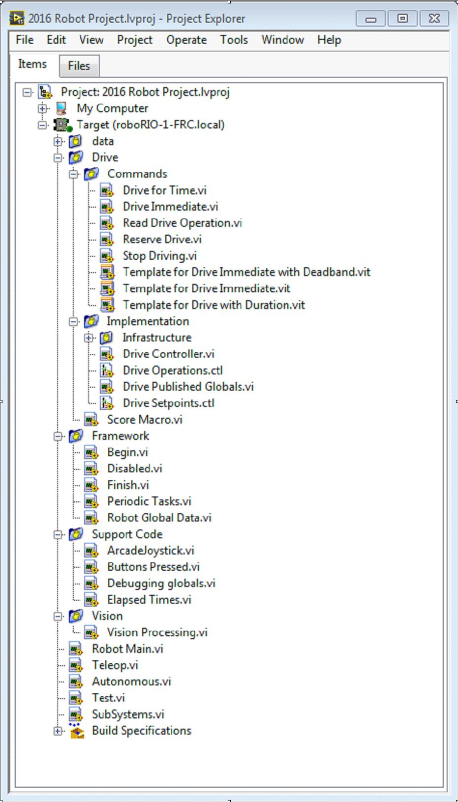
65 Page 65
66 My Computer the items that define operation on the computer that the project was loaded on. For a robot project, this is used as a simulation target and is populated with simulation files. Sim Support Files folder containing 3D CAD models and description files for the simulated robot. Robot Simulation Readme.html documents the PWM channels and robot info you will need in order to write robot code that matches the wiring of the simulated robot. Dependencies shows the files used by the simulated robot s code. This will populate when you designate the code for the simulated robot target. Build Specifications will contain the files that define how to build and deploy code for the simulated robot target. Target (roborio-team-frc.local) the items that define operation on the roborio located at (address). Drive subsystem implementation and commands for the robot drive base. This serves as a custom replacement for the WPILib RobotDrive VIs. Framework VIs used for robot code that is not part of a subsystem that are not used very often. Begin called once when robot code first starts. This is useful for initialization code that doesn t belong to a particular subsystem. Disabled called once for each disabled packet and can be used to debug sensors when you don t want the robot to move. Finish during development, this may be called when robot code finishes. Not called on abort or when power is turned off. Periodic Tasks a good place for ad hoc periodic loops for debugging or monitoring Robot Global Data useful for sharing robot information that doesn t belong to a subsystem. Page 66
67 Support Code debugging and code development aids. Vision subsystem and commands for the camera and image processing. Robot Main.vi Top level VI that you will run while developing code. Autonomous.vi VI that runs during autonomous period. Teleop.vi VI that is called for each TeleOp packet. Test.vi VI that runs when driver station is in test mode. SubSystems.vi VI that contains and starts all subsystems. Dependencies shows the files used by the robot code. Build Specifications used to build and run the code as a startup application once code works correctly. Page 67

68 Drive Subsystem Project Explorer Commands: This folder contains the command VIs that request the controller carry out an operation. It also contains templates for creating additional drive commands. Note: After creating a new command, you may need to edit Drive Setpoints.ctl to add or update fields that controller uses to define the new operation. You also need to go into the Drive Controller.vi and modify the case structure to add a case for every value. Implementation: These are the VIs and Controls used to build the subsystem. Infrastructure VIs Drive Check for New Command: It is called each iteration of the controller loop. It checks for new commands, updates timing data, and upon completion notifies a waiting command. Drive Command Helper.vi: Commands call this VI to notify the controller that a new command has been issued. Page 68
69 Drive Controller Initialization.vi: It allocates the notifier and combines the timing, default command, and other information into a single data wire. Drive Controller.vi: This VI contains the control/state machine loop. The panel may also contain displays useful for debugging. Drive Operation.ctl: This typedef defines the operational modes of the controller. Many commands can share an operation. Drive Setpoint.ctl: It contains the data fields used by all operating modes of the Drive subsystem. Drive Published Globals.vi: A useful place for publishing global information about the drive subsystem. Part 2: Initializing the Drive Subsystem There are green comments on the controller s block diagram that point out key areas that you will want to know how to edit. The area to the left of the control loop will execute once when the subsystem starts up. This is where you will typically allocate and initialize all I/O and state data. You may publish the I/O refnums, or you may register them for Test Mode Only to keep them private so that other code cannot update motors without using a command. Page 69


70 Note: Initializing the resources for each subsystem in their respective Controller.vi rather than in Begin.vi improves I/O encapsulation, reducing potential resource conflicts and simplifies debugging. Page 70

71 Part of the initialization is to select the default operation and set point values when no other operation is being processed. Inside the control loop is a case statement where operations are actually implemented. Set point values, iteration delay, iteration count, and sensors can all have influence on how the subsystem operates. This case structure has a value for each operation state of the subsystem. Page 71

72 Each iteration of the controller loop will optionally update the Trace VI. The framework already incorporates the subsystem name, operation, and description, and you may find it helpful to format additional set point values into the trace information. Open the Trace VI and click Enable while the robot code is running to current setpoints and commands sent to each subsystem. The primary goal of the controller is to update actuators for the subsystem. This can occur within the case structure, but many times, it is beneficial to do it downstream of the structure to ensure that values are always updated with the correct value and in only one location in the code. Page 72
73 Part 3: Drive Subsystem Shipped Commands There are 3 shipped example commands for each new subsystem: Drive For Time.vi This VI sets the motors to run for a given number of seconds. It optionally synchronizes with the completion of the command. The Drive for Time case will operate the motors at the set point until the timer elapses or a new command is issued. If the motors have the safety timeout enabled, it is necessary to update the motors at least once every 100ms. This is why the code waits for the smaller of the remaining time and 50ms. Page 73
74 Drive Immediate.vi Gets the desired left and right speeds for the motors and will set the motors immediately to those set points. The Immediate case updates the motors to the set point defined by the command. The command is not considered finished since you want the motors to maintain this value until a new command comes in or until a timeout value. The timeout is useful anytime a command includes a dead band. Small values will not be requested if smaller than the dead band, and will result in growling or creeping unless the command times out. Page 74

75 Stop Driving.vi Zero the drive motors, making the robot stationary. The Reserve command turns off the motors and waits for a new command. When used with a named command sequence, reserve identifies that the drive subsystem is part of a sequence, even if not currently moving the robot. This helps to arbitrate subsystem resource between simultaneously running commands. Page 75
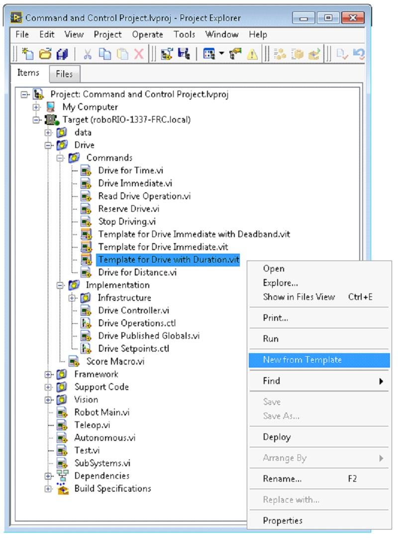
76 Part 4: Creating New Commands The Command and Control framework allows users to easily create new commands for a subsystem. To Create a new command open the subsystem folder/commands In the project explorer window, choose one of the VI Templates to use as the starting point of your new command, right click, and select New From Template. Immediate: This VI notifies the subsystem about the new setpoint. Immediate with deadband: This VI compares the input value to the deadband and optionally notifies the subsystem about the new setpoint. This is very useful when joystick continuous values are being used. With duration: This VI notifies the subsystem to perform this command for the given duration, and then return to the default state. Synchronization determines whether this VI Starts the operation and returns immediately, or waits for the operation to complete. The first option is commonly used for TeleOp, and the second for Autonomous sequencing. In this example we will add the new command Drive for Distance. Page 76
77 Page 77
78 First, save the new VI with a descriptive name such as Drive for Distance. Next, determine whether the new command needs a new value added the Drive Operations enum typedef. The initial project code already has an enum value of Drive for Distance, but the following image shows how you would add one if needed. Page 78

79 If a command needs additional information to execute, add it to the setpoints control. By default, the Drive subsystem has fields for the Left Setpoint, Right Setpoint, and Duration along with the Page 79

80 operation to be executed. The Drive for Distance command could reuse Duration as distance, but let s go ahead and add a numeric control to the Drive Setpoints.ctl called Distance (feet). Once that we have all of the fields needed to specify our command, we can modify the newly created Drive for Distance.vi. As shown below, select Drive for Distance from the enum s drop down menu and add a VI parameters to specify distance, speeds, etc. If the units do not match, the command VI is a great place to map between units. Page 80
81 Next, add code to the Drive Controller to define what happens when the Drive for Distance command executes. Right click on the Case Structure and Duplicate or Add Case for Every Value. This will create a new Drive for Distance case. Page 81


82 In order to access new setpoint fields, grow the Access Cmd setpoints unbundle node. Open your encoder(s) on the outside, to the left of the loop. In the new diagram of the case structure, we added a call to reset the encoder on the first loop iteration and read it otherwise. There is also some simple code that compares encoder values and updates the motor power. If new controls are added to the setpoints cluster, you should also consider adding them to the Trace. The necessary changes are shown in the image below. Part 5: Creating a Subsystem In order to create a new subsystem, right click on the roborio target and select New» Subsystem. In the pop up dialog box, enter the name of the subsystem, list the operational modes, and specify the color of the icon. Page 82

83 When you click OK, the subsystem folder will be generated and added to the project disk folder and tree. It will contain a base implementation of the VIs and controls that make up a subsystem. A call to the new controller will be inserted into the Subsystems VI. The controller VI will open, ready for you to add I/O and implement state machine or control code. Generated VI icons will use the color and name provided in the dialog. The generated code will use typedefs for set point fields and operations. Page 83


84 Below is the block diagram of the newly created subsystem. This code will be generated automatically when you create the subsystem. Page 84
85 LabVIEW Resources Page 85

86 LabVIEW Porting Guide to 2015 LabVIEW teams will find the VIs and palletes in the 2015 FRC version of LabVIEW very familiar. Teams should only need to make minor changes to get a 2014 program to run on a roborio. This document highlights changes in the 2015 VIs and how they correspond with the old code. Joystick Get The old Joystick Get VIs have been replaced with a single VI that provides an array (instead of a cluster) for each type of input (axes, buttons and POVs). POVs have been changed to be a unique output and to an angle (0 to 360 with -1 indicating not pressed). Joysticks, axes, POVs, and buttons (in LabVIEW, buttons are still 1 based in C++\Java) are 0 based The DS will now support up to 6 joysticks with a dynamic number of axes, buttons and POVs Page 86
.")

87 Module and Channel numbers As the roborio has no modules, module numbers have been changed to a Controller number which currently has only one option (and therefore does not need to be wired). Channel numbers have been changed to be 0-based (matching the channel numbers on the roborio). Compressor Compressor code is no longer required (when using the PCM) unless you wish to get advanced information from or exercise control over the compressor. Opening any solenoid on the PCM the compressor is attached to will automatically enable the closed loop control for that compressor. Sensor "Start/Stop" - Encoders, Counters, etc. Sensors which uses to require explicit Start and Stop VIs have been changed to Start on Open. Stop has been removed. If you wish to keep track of values over a single explicit period, call Reset Page 87
.")

88 at the start of the period. If you wish to keep track of values over multiple explicit periods, you will have to track this in your code (Reset at the start of each period and keep track of the sum in your code). DS User Messages The User messages window on the Driver Station has been removed, therefore this functionality has been removed from the pallete. As a replacement, the default Dashboard contains a number of controls and indicators of different types on the "Basic" tab that teams may wish to use to display robot information or provide input. To write to these controls, use the SmartDashboard VIs, the key names to use are listed on the Dashboard. File IO On the crio, files could be written to the root drive (C:\) or you could create subfolders within that location. On the roborio you should write files to /home/lvuser or create a subdirectory underneath that for your files. Note that a File Create will fail if the directory does not exist so you will need to programatically create the directory or create it via SFTP/SSH before trying to create a file in that directory. Page 88

89 DS IO, Enhanced IO, and Kinect The Cypress Firsttouch board support and Kinect server support has been removed from the DS so these palletes and VIs have been removed. Teams can use the Dashboard or USB HID devices to replace the Cypress board functionality. The TI Launchpad and 16 Hertz Leonardo++ included in your Kit of Parts can both be programmed to appear as HID devices to be used for custom I/O (click the links for more info). Teams wishing to use the Kinect as an input device will need to modify the Kinect server to send data directly to the robot using Network Tables or one of the ports available on the field network. SPI With the built-in SPI ports, the SPI Ooen and configuration has been simplified and consolidated to a single VI: The Clock Phase and Clock Active state have been combined into a mode Enum The "MSB First" boolean input has been removed, you will need to flip your data before sending if you need to send LSB first The "Frame Mode" input has been removed. The SPI port on the roborio does not support this. The "Bits per word" input has been removed. The SPI port on the roborio does not support this. The "Chip Select Active Low" input on the 2014 config VI has been flipped to be a "Chip Select Active High" input on the 2015 open VI. Page 89

90 I2C The Compatibility mode input has been removed from the I2C Read and I2C Write VIs. This is not necessary on the roborio I2C. I2C addressing has changed from an 8-bit address on the crio to a 7-bit address on the roborio. An 8-bit address includes the bit for whether an operation is a read or write while a 7-bit address does not (the R/W bit is appended by the driver when performing the operation). Camera The Camera VIs have been modified to support USB cameras (tested with the Microsoft Lifecam HD3000). For complete information see the examples and the Vision Processing section. Page 90


91 New VIs In addition to the changes, a number of new VIs have been added to support the new capabilities of the roborio and the new Control System. For additional help with these VIs, drag them into your project, right click on them and select Help. Joystick Info New VIs have been added to get information such as the name, type, and axis, button and POV count of each Joystick and to set HID outputs for devices which support them (such as the TI Launchpad). Potentiometer Page 91


92 These VIs use the output voltage of the analog supply to provide a normalized (0 to 1) reading from a potentiometer or other ratiometric sensor Switch These VIs help abstract switches used as Limit Switches or Counting Switches. Accelerometer The accelerometer VIs have been generalized to apply to the internal accelerometer, analog accelerometer, or the ADX345 connected to either the I2C or SPI interface. Page 92


93 Analog Output These VIs control the 2 Analog Outputs on the MXP port Power These VIs provide information about the roborio power state, PCM faults, current, and voltage, PDP faults, current and voltage, and the enabled state of the FPGA outputs. Page 93
94 LabVIEW Resources To learn more about programming in LabVIEW and specifically programming FRC robots in LabVIEW, check out the following resources. LabVIEW Basics National Instruments provides a combination of videos and traditional text/picture tutorials on the basics of LabVIEW. These tutorials can help you get acquainted with the LabVIEW environment and the basics of the graphical, dataflow programing model used in LabVIEW. FRC Mastery Videos Though they have not been updated to match changes to the robot framework code, the FRC Mastery series of videos are still a helpful guide to understanding the basics of FRC programming in LabVIEW. Most or all of the content in Steps 1, 2, 3, 4, 6, and 7 of the 2011 FRC Steps to Robot Success will match fairly closely to the 2015 code. NI FRC Tutorials National Instruments also hosts many FRC specific tutorials and presentations ranging from basic to advanced. For an in-depth single resource check out the FRC Basic and Advanced Training Classes linked near the bottom of the page. Page 94
95 Installed Tutorials and Examples There are also tutorials and examples for all sorts of tasks and components provided as part of your LabVIEW installation. To access the tutorials, from the LabVIEW Splash screen (the screen that appears when the program is first launched) click on the Tutorials tab on the left side. Note that the tutorials are all in one document, so once it is open you are free to browse to other tutorials without returning to the splash screen. To access the examples either click the Support tab, then Find FRC Examples or anytime you're working on a program open the Help menu, select Find Examples and open the FRC Robotics folder. Page 95

96 Waiting for Target to Respond - Recovering from bad loops If you download LabVIEW code which contains an unconstrained loop (a loop with no delay) it is possible to get the roborio into a state where LabVIEW is unable to connect to download new code. This document explains the process required to load new, fixed, code to recover from this state. The Symptom Page 96
 but the steps described here should resolve most or all of them.")
97 The primary symptom of this issue is attempts to download new robot code hang at the "Waiting for the target (Target) to respond" step as shown above. Note that there are other possible causes of this symptom (such as switching from a C++\Java program to LabVIEW program) but the steps described here should resolve most or all of them. Click Cancel to close the download dialog. The Problem One common source of this issue is unconstrained loops in your LabVIEW code. An unconstrained loop is a loop which does not contain any delay element (such as the one on the left). If you are unsure where to begin looking, Disabled.VI, Periodic Tasks.VI and Vision Processing.VI are the common locations for this type of loop. To fix the issue with the code, add a delay element such as the Wait (ms) VI from the Timing palette, found in the right loop. Page 97
98 Set No App Using the roborio webserver (see the article RoboRIO Webdashboard for more details). Check the box to "Disable RT Startup App". Reboot Reboot the roborio, either using the Reset button on the device or by click Restart in the top right corner of the webpage. Page 98
99 Clear No App Using the roborio webserver (see the article RoboRIO Webdashboard for more details). Uncheck the box to "Disable RT Startup App". Load LabVIEW Code Load LabVIEW code (either using the Run button or Run as Startup). Make sure to set LabVIEW code to Run as Startup before rebooting the roborio or you will need to follow the instructions above again. Page 99
100 Talon SRX CAN The Talon SRX motor controller is a CAN-enabled "smart motor controller" from Cross The Road Electronics/VEX Robotics. The Talon SRX can be controlled over the CAN bus or PWM interface. When using the CAN bus control, this device can take inputs from limit switches and potentiometers, encoders, or similar sensors in order to perform advanced control such as limiting or PID(F) closed loop control on the device. Extensive documentation about programming the Talon SRX in all three FRC languages can be found in the Talon SRX Software Reference Manual on CTRE's Talon SRX product page. Note: CAN Talon SRX has been removed from WPILib. See this blog for more info and find the CTRE Toolsuite installer here: hro.html#product_tabs_technical_resources Page 100

101 How To Toggle Between Two Camera Modes This code shows how to use a button to toggle between two distinct camera modes. The code consists of four stages. In the first stage, the value of a button on the joystick is read. Next, the current reading is compared to the previous reading using a Feedback Node and some Boolean arithmetic. Together, these ensure that the camera mode is only toggled when the button is initially pressed rather than toggling back and forth multiple times while the button is held down. After that, the camera mode is toggled by masking the result of the second stage over the current camera mode value. This is called bit masking and by doing it with the XOR function the code will toggle the camera mode when the second stage returns true and do nothing otherwise. Finally, you can insert the code for each camera mode in the case structure at the end. Each time the code is run, this section will run the code for the current camera mode. Page 101
102 LabVIEW Examples and Tutorials Popular Tutorials Autonomous Timed Movement Tutorial Move your robot autonomously based on different time intervals See more on Autonomous Movement Basic Motor Control Tutorial Setup your roborio motor hardware and software Learn to setup the FRC Control System and FRC Robot Project See more on Motor Control Image Processing Tutorial Learn basic Image Processing techniques and how to use NI Vision Assistant See more on Cameras and Image Processing PID Control Tutorial What is PID Control and how can I implement it? Command and Control Tutorial What is Command and Control? How do I implement it? Driver Station Tutorial Get to know the FRC Driver Station Test Mode Tutorial Page 102
103 Learn to setup and use Test Mode Looking for more examples and discussions? Search through more documents or post your own discussion, example code, or tutorial by clicking here! Don t forget to mark your posts with a tag! Page 103

104 Add an Independent Motor to a Project Once your drive that controls the wheels is all set, you might need to add an additional motor to control something completely independent of the wheels, such as an arm. Since this motor will not be part of your tank, arcade, or mecanum drive, you'll definitely want independent control of it. These VI Snippets show how to set up a single motor in a project that may already contain a multimotor drive. If you see the HAND>ARROW>LABVIEW symbol, just drag the image into your block diagram, and voila: code! Ok, here's how you do it. FIRST, create a motor reference in the Begin.vi, using the Motor Control Open VI and Motor Control Refnum Registry Set VI. These can be found by right-clicking in the block diagram and going to WPI Robotics Library>>RobotDrive>>Motor Control. Choose your PWM line and name your motor. I named mine "Lift Motor" and connected it to PWM 7. (I also included and enabled the Motor Control Safety Config VI, which automatically turns off the motor if it loses connection.) Now, reference your motor (the name has to be exact) in the Teleop.vi using the Motor Control Refnum Registry Get VI and tell it what to do with the Motor Control Set Output VI. These are in the same place as the above VIs. Page 104
.")


105 For example, the next snippet tells the Lift Motor to move forward if button 4 is pressed on Joystick 0 and to remain motionless otherwise. For me, button 4 is the left bumper on my Xbox style controller ("Joystick 0"). For much more in-depth joystick button options, check out How to Use Joystick Buttons to Control Motors or Solenoids. Finally, we need to close the references in the Finish.vi (just like we do with the drive and joystick), using the Motor Control Refnum Registry Get VI and Motor Control Close VI. While this picture shows the Close VI in a flat sequence structure by itself, we really want all of the Close VIs in the same frame. You can just put these two VIs below the other Get VIs and Close VIs (for the joystick and drive). I hope this helps you program the best robot ever! Good luck! Page 105

106 Keyboard Navigation with the roborio This example provides some suggestions for controlling the robot using keyboard navigation in place of a joystick or other controller. In this case, we use the A, W, S, and D keys to control two drive motors in a tank drive configuration. The first VI Snippet is the code that will need to be included in the Dashboard Main VI. You can insert this code into the True case of Loop 1. The code opens a connection to the keyboard before the loop begins, and on each iteration it reads the pressed key. This information is converted to a string, which is then passed to the Teleop VI in the robot project. When Loop 1 stops running, the connection to the keyboard is closed. The second VI Snippet is code that should be included in the Teleop VI. This reads the string value from the Dashboard that indicates which key was pressed. A Case Structure then determines which values should be written to the left and right motors, depending on the key. In this case, W is forward, A is left, D is right, and S is reverse. Each case in this example runs the motors at half speed. You can keep this the same in your code, change the values, or add additional code to Page 106
107 allow the driver to adjust the speed, so you can drive fast or slow as necessary. Once the motor values are selected, they are written to the drive motors, and motor values are published to the dashboard. Page 107

108 Making a One-Shot Button Press When using the Joystick Get Values function, pushing a joystick button will cause the button to read TRUE until the button is released. This means that you will most likely read multiple TRUE values for each press. What if you want to read only one TRUE value each time the button is pressed? This is often called a "One-Shot Button". The following tutorial will show you how to create a subvi that you can drop into your Teleop.vi to do this. FIRSTly, create a new VI in the Support Code folder of your project. Now on the block diagram of the new VI, drop in the following code snippet. Page 108

109 This code uses a function called the Feedback Node. We have wired the current value of the button into the left side of the feedback node. The wire coming out of the arrow of the feedback node represents the previous value of the button. If the arrow on your feedback node is going the opposite direction as shown here, right click to find the option to reverse the direction. When a button is pressed, the value of the button goes from FALSE to TRUE. We want the output of this VI to be TRUE only when the current value of the button is TRUE, and the previous value of the button is FALSE. Next we need to connect the boolean control and indicator to the inputs and outputs of the VI. To do this, first click the block on the connector pane, then click the button to connect the two (see the diagram below). Repeat this for the indicator. Page 109

110 Next, we need to change the properties of this VI so that we can use multiples of this VI in our TeleOp.vi. Right click the VI Icon and go to VI Properties. Then select the category "Execution" and select "Preallocated clone reentrant execution". Page 110
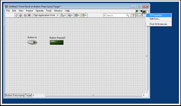
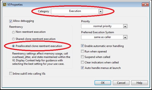
111 Page 111

112 Lastly, we should change the VI Icon to be more descriptive of the VI's function. Right click the Icon and go to Edit Icon. Create a new Icon. Finally, save the VI with a descriptive name. You can now drag and drop this VI from the Support Files folder into your TeleOp.vi. Here's an example of how you could use this VI. Page 112

113 Button_Press.vi Page 113
114 Adding Safety Features to Your Robot Code A common problem with complex projects is making sure that all of your code is executing when you expect it to. Problems can arise when tasks with high priority, long execution times, or frequent calls hog processing power on the roborio. This leads to what is known as "starvation" for the tasks that are not able to execute due to the processor being busy. In most cases this will simply slow the reaction time to your input from the joysticks and other devices. However, this can also cause the drive motors of your robot to stay on long after you try to stop them. To avoid any robotic catastrophes from this, you can implement safety features that check for task input starvation and automatically shut down potentially harmful operations. There are built-in functions for the motors that allow easy implementation of safety checks. These functions are: Robot Drive Safety Configuration Motor Drive Safety Configuration Relay Safety Configuration PWM Safety Configuration Solenoid Safety Configuration Robot Drive Delay and Update Safety In all of the Safety Configuration functions, you can enable and disable the safety checks while your programming is running and configure what timeout you think is appropriate. The functions keep a cache of all devices that have the safety enabled and will check if any of them have exceeded their time limit. If any has, all devices in the cache will be disabled and the robot will come to an immediate stop or have its relay/pwm/solenoid outputs turned off. The code below demonstrates how to use the Drive Safety Configuration functions to set a maximum time limit that the motors will receive no input before being shut off. Page 114

115 To test the safety shut-off, try adding a Wait function to the loop that is longer than your timeout! The final function that relates to implementing safety checks--robot Drive Delay and Update Safety--allows you to put the roborio in Autonomous Mode without exceeding the time limit. It will maintain the current motor output without making costly calls to the Drive Output functions, and will also make sure that the safety checks are regularly updated so that the motors will not suddenly stop. Overall, it is highly recommended that some sort of safety check is implemented in your project to make sure that your robot is not unintentionally left in a dangerous state! Page 115

116 How to Use Joystick Buttons to Control Motors or Solenoids As we all get our drive systems working, we are moving on to connecting our auxiliary devices such as motors and solenoids. With this, we will generally use joystick buttons to control these devices. To get started with this, we'll go through several ways to control devices with joystick buttons. Did you know that you can click and drag a VI Snippet from a document like this right into your LabVIEW code? Try it with the snippets in this document. Setup: No matter what the configuration, you'll need to add one, two, or more (if you're really excited) joysticks to the "Begin.vi". The first example uses 2 joysticks and the others only use one. Give each one a unique name so we can use it in other places, like the snippet below. I named them "LeftStick" and "RightStick" because they are on the left and right sides of my desk. If your joysticks are already configured, great! You can skip this step. The rest of the code in this document will be placed in the "Teleop.VI" This is where we will be programming our joystick buttons to control different aspects of our motors or solenoids. Page 116


117 Scenario 1: I want a motor to move one way when I press one button and the other way when I press a different button. This code uses button 0 on two different joysticks to control the same motor. If button 0 on LeftStick is pressed, the motor moves backward, and if button 0 on RightStick is pressed, the motor moves forward. If both buttons are pressed or neither button is pressed, the motor doesn't move. Here I named my motor reference "Motor5", but you can name your motor whatever you want in the "Begin.vi" You may want to use multiple buttons from the same joystick for control. For an example of this, look at the following VI snippet or the VI snippet in Scenario 2. Here I used joystick buttons 0 and 2, but feel free to use whatever buttons you need. Page 117
118 Scenario 2: I want different joystick buttons move at various speeds. This example could be helpful if you need to have one motor do different things based on the buttons you press. For instance, let's say my joystick has a trigger (button 0) and 4 buttons on top (buttons 1 through 4). In this case, the following buttons should have the following functions: button 1 - move backward at half speed button 2 - move forward at half speed button 3 - move backward at 1/4 speed button 4 - move forward at 1/4 speed trigger - full speed ahead! (forward at full speed) We would then take the boolean array from the "JoystickGetValues.vi" and wire it to a "Boolean Array to Number" node (Numeric Palette-Conversion Pallette). This converts the boolean array to a number that we can use. Wire this numeric to a case structure. Each case corresponds to a binary representation of the values in the array. In this example, each case corresponds to a one-button combination. We added six cases: 0 (all buttons off), 1 (button 0 on), 2 (button 1 on), 4 (button 2 on), 8 (button 3 on), and 16 (button 4 on). Notice we skipped value 3. 3 would correspond to buttons 0 and 1 pressed at the same time. We did not define this in our requirements so we'll let the default case handle it. It might be helpful to review the LabVIEW 2014 Case Structure Help document here: There are also 3 Community Tutorials on case structures here: Page 118
 the motor will stop.")
119 Since our requirements were simple, we only need a single constant in each case. For case 1 (full ahead) we use a 1, for case 2 (half back) we use a -0.5, etc. We can use any constant value between 1 and -1. I left case 0 as the default so if multiple buttons are pressed (any undefined state was reached) the motor will stop. You of course are free to customize these states however you want. Scenario 3: I want to control a solenoid with my joystick buttons. By now, we are familiar with how the joystick outputs the buttons in an array of booleans. We need to index this array to get the button we are interested in, and wire this boolean to a select node. Since the "Solenoid Set.vi" requires a Enum as an input, the easiest way to get the enum is to right click the "Value" input of the "Solenoid Set.vi" and select "Create Constant". Duplicate this constant and wire one copy to the True terminal and one to the False terminal of the select node. Then wire the output of the select node to the "Value" input of the solenoid VI. Hope this helps! Feel free to comment below. Happy Roboting! Page 119

120 Local and Global Variables in LabVIEW for FRC This example serves as an introduction to local and global variables, how they are used in the default LabVIEW for FRC Robot Project, and how you might want to use them in your project. Local variables and global variables may be used to transfer data between locations within the same VI (local variables) or within different VI s (global variables), breaking the conventional Data Flow Paradigm for which LabVIEW is famous. Thus, they may be useful when, for whatever reason, you cannot wire the value directly to the node to another. Note: One possible reason may be that you need to pass data between consecutive loop iterations; Miro_T covered this in this post. It should also be noted that the feedback node in LabVIEW may be used as an equivalent to the shift register, although that may be a topic for another day! Introduction to Local and Global Variables Local variables may be used within the same VI. Create a local variable by right-clicking a control or indicator on your Front Panel: You may create a local variable from the Structures palette on the block diagram as well. When you have multiple local variables in one VI, you can left-click to choose which variable it is: Page 120


121 Global variables are created slightly differently. Add one to the block diagram from the Structures palette, and notice that when you double-click it, it opens a separate front panel. This front panel does not have a block diagram, but you add as many entities to the front panel as you wish and save it as a *.vi file: Note: Be very careful to avoid race conditions when using local and global variables! Essentially, make sure that you are not accidentally writing to the same variable in multiple locations without a way to know to which location it was last written. For a more thorough explanation, see this help document. How They are Used in the Default LabVIEW for FRC Robot Project Global variables for Enable Vision and Image Size are written to during each iteration of the Robot Main VI Page 121

122 read in each iteration of the Vision Processing VI: And then Page 122


123 This allows the user, when deploying to Robot Main VI from the LabVIEW Development Environment, to enable/ disable vision and change the image size from Robot Main s Front Panel. How Can You Use Them in Your Project? Check out the block diagram for the Periodic Tasks VI. Perhaps there is some value, such as a boolean, that may be written to a global variable in the Teleop VI, and then read from in the Periodic Tasks VI. You can then decide what code or values to use in the Periodic Tasks VI, depending on the boolean global variable: Page 123

124 Using the Compressor in LabVIEW This snippet shows how to set up your roborio project to use the Pneumatic Control Module (PCM). The PCM automatically starts and stops the compressor when specific pressures are measured in the tank. In your roborio program, you will need to add the following VIs. For more information, check out the following links: Begin VI Place this snippet in the Begin.vi. Teleop VI Place this snippet in the Teleop.vi. This portion is only required if you are using the outputs for other processes. Page 124

125 Finish VI Place this snippet in Close Refs, save data, etc. frame of the Finish.vi. Page 125
FRC LABVIEW PROGRAMMING
 FRC LABVIEW PROGRAMMING Last Updated: 01-07-2017 Table of Contents Setting up the Development Environment...3 Installing LabVIEW for FRC 2017 (LabVIEW only)...4 Installing the FRC 2017 Update Suite (All
Command and Control Tutorial
 Command and Control Tutorial Introduction Command and Control is a new LabVIEW template added for the 2016 season which organizes robot code into commands and controllers for a collection of robot-specific
I C ROBOTICS FRC ROBOT PROGRAMMING GETTING STARTED WITH LABVIEW
 I C ROBOTICS FRC ROBOT PROGRAMMING GETTING STARTED WITH LABVIEW What are we going to do? Work through all the steps from software download and installation through hardware configuration and deployment
2015 FRC Software Component Overview
 2015 FRC Software Component Overview The 2015 FRC Control System consists of a wide variety of mandatory and optional software components designed to assist you in the design, development and debugging
Last Updated: BETA TESTING
 Last Updated: 10-13-2017 2018 BETA TESTING Table of Contents 2018 Beta Testing - Getting Started...3 Welcome...4 Accessing the 2018 Beta Project...5 Reporting Progress...8 Trackers - Reporting Bugs...
GETTING STARTED WITH JAVA
 GETTING STARTED WITH JAVA Last Updated: 07-11-2016 Table of Contents Setting up the Development Environment...3 Installing the Java development tools...4 Configuring the NetBeans installation... 12 Understanding
FRC JAVA PROGRAMMING
 FRC JAVA PROGRAMMING Table of Contents Setting up the Development Environment... 5 Installing Eclipse (C++/Java)... 6 Installing the FRC 2015 Update Suite (All Languages)... 30 Installing Java 8 on the
GETTING STARTED WITH JAVA
 GETTING STARTED WITH JAVA Last Updated: 12-04-2018 Table of Contents Setting up the Development Environment...3 Installing the Java development tools...4 Configuring the NetBeans installation... 11 Understanding
FRC C++ PROGRAMMING Last Updated:
 FRC C++ PROGRAMMING Last Updated: 01-16-2018 Table of Contents Setting up the Development Environment...5 Installing Eclipse (C++/Java)...6 Installing the FRC Update Suite (All Languages)... 29 FRC C++
Last Updated: FRC 2019 BETA
 Last Updated: 10-29-2018 FRC 2019 BETA Table of Contents Alpha Test (Publically available)...4 Alpha Test Info...5 Installing VS Code...6 VS Code Basics and WPILib in VS Code... 16 Creating a new WPILib
FRC C++ PROGRAMMING Last Updated:
 FRC C++ PROGRAMMING Last Updated: 10-02-2017 Table of Contents Setting up the Development Environment...5 Installing Eclipse (C++/Java)...6 Installing the FRC 2018 Update Suite (All Languages)... 27 FRC
Updating and Configuring Pneumatics Control
 Updating and Configuring Pneumatics Control Module and Power This document describes the process of updating the firmware on the Cross the Road Electronics CAN devices. Note: Google Chrome is removing
INTRODUCTION TABLE OF CONTENTS 1 INTRODUCTION WELCOME TO THE 2009 FRC CONTROL SYSTEM Suggestions for Getting Started 2
 Section 1 INTRODUCTION TABLE OF CONTENTS 1 INTRODUCTION 2 1.1 WELCOME TO THE 2009 FRC CONTROL SYSTEM 2 1.1.1 Suggestions for Getting Started 2 1.2 TECHNICAL SUPPORT FOR THE 2009 FRC CONTROL SYSTEM 2 1.3
LabVIEW & FRC. BAA Fall Education Day 2015
 LabVIEW & FRC BAA Fall Education Day 2015 Who am I? Jayesh Jariwala, P.E. Univ of Delaware BChE 98 Process control engineer for 17+ years Working at Applied Control Engineering, Inc FRC Mentor for 6 years
FRC C++ PROGRAMMING Last Updated:
 FRC C++ PROGRAMMING Last Updated: 02-17-2017 Table of Contents Setting up the Development Environment...5 Installing Eclipse (C++/Java)...6 Installing the FRC 2017 Update Suite (All Languages)... 27 FRC
IT Essentials v6.0 Windows 10 Software Labs
 IT Essentials v6.0 Windows 10 Software Labs 5.2.1.7 Install Windows 10... 1 5.2.1.10 Check for Updates in Windows 10... 10 5.2.4.7 Create a Partition in Windows 10... 16 6.1.1.5 Task Manager in Windows
Installing Eclipse (C++/Java)
") Installing Eclipse (C++/Java) The 2017 suite of text-based languages, Java and C++, utilize the current version of Eclipse as a development environment. The FRC specific tools for the chosen language are
Installing Eclipse (C++/Java) The 2017 suite of text-based languages, Java and C++, utilize the current version of Eclipse as a development environment. The FRC specific tools for the chosen language are
FRC JAVA PROGRAMMING Last Updated:
 FRC JAVA PROGRAMMING Last Updated: 12-13-2017 Table of Contents Setting up the Development Environment...5 Installing Eclipse (C++/Java)...6 Installing the FRC Update Suite (All Languages)... 29 Installing
Getting Started with the 2013 FRC Control System
 Getting Started with the 2013 FRC Control System Getting Started with the 2013 FRC Control System... 2 How to Set Up Your 2013 Driver Station... 8 How to Configure Your CompactRIO... 10 How to Build and
FRC JAVA PROGRAMMING Last Updated:
 FRC JAVA PROGRAMMING Last Updated: 10-01-2017 Table of Contents Setting up the Development Environment...5 Installing Eclipse (C++/Java)...6 Installing the FRC 2018 Update Suite (All Languages)... 27 Installing
The "Hello world" of FRC robot programming
 The "Hello world" of FRC robot programming Here's how to create the shortest possible robot program that actually does something useful. In this case, it provides tank steering in teleop mode and drives
COMMAND BASED PROGRAMMING
 COMMAND BASED PROGRAMMING Last Updated: 09-11-2016 Table of Contents Command based programming...4 What is Command based programming?...5 Creating a command based robot project in C++... 10 Installing
Getting Started with the SmartDashboard
 Getting Started with the SmartDashboard The SmartDashboard typically runs on the Driver Station computer and will do two functions: 1. View robot data that is displayed as program status as your program
Getting Started with Microsoft Kinect for FRC
 v2.3 January 3 rd, 2012 Page 1 of 14 Getting Started with Microsoft Kinect for FRC Before proceeding, make sure you do not have any existing Kinect drivers on your computer. If you have previously installed
Creating a robot project
 Creating a robot project Liquid error: No route matches {:action=>"show", :controller=>"spaces/chapters", :space_id=>"3120", :manual_id=>"7952", :id=>nil} Launching WindRiver Workbench WindRiver Workbench
FRC Driver Station Powered by NI LabVIEW
 This article describes the use and features of the 2016. For information on installing the Driver Station software see this document. Starting the FRC Driver Station The FRC Driver Station can be launched
FRC Driver Station Powered by NI LabVIEW
 FRC Driver Station Powered by NI LabVIEW This article describes the use and features of the FRC Driver Station Powered by NI LabVIEW. For information on installing the Driver Station software see this
Using the Axis Camera at Single Network Events
 Using the Axis Camera at Single Network Events The 2015 convention for using the Axis camera uses mdns with the camera name set to axiscamera.local At home this works fine as there is only one camera on
FRC JAVA PROGRAMMING Last Updated:
 FRC JAVA PROGRAMMING Last Updated: 01-24-2018 Table of Contents Setting up the Development Environment...5 Installing Eclipse (C++/Java)...6 Installing the FRC Update Suite (All Languages)... 29 Creating
Driver Station Log File Viewer
 Driver Station Log File Viewer In an effort to provide information to aid in debugging, the FRC Driver Station creates log files of important diagnostic data while running. These logs can be reviewed later
Installing the C++ Development Tools
 Installing the C++ Development Tools WindRiver Workbench is the development environment used for creating and loading C++ code onto a crio for FRC. This document describes how to install the Wind River
This is an inspection failure, not meeting the requirement of >10k Ohm between either PD battery post and chassis.
 Troubleshooting This is a document put together by CSA Laura Rhodes that contains a lot of information about troubleshooting steps for a lot of common control system problems encountered at events. No
SPARTAN ROBOTICS FRC 971
 SPARTAN ROBOTICS FRC 971 Controls Documentation 2015 Design Goals Create a reliable and effective system for controlling and debugging robot code that provides greater flexibility and higher performance
User Guide. Introduction. Requirements. Installing and Configuring. C Interface for NI myrio
 User Guide C Interface for NI myrio Introduction The C interface for NI myrio is designed for users who want to program the NI myrio using the C programming language or a programming language other than
Imaging your Classmate (Veteran Image
 Imaging your Classmate (Veteran Image Download) This document describes the procedure for creating a bootable USB drive to restore the 2017 FRC image on a Classmate computer. Note that Veteran teams are
Last Updated: ROBOTBUILDER
 Last Updated: 06-11-2016 ROBOTBUILDER Table of Contents The basic steps to create a robot program...4 Overview of RobotBuilder...5 Starting RobotBuilder... 12 The RobotBuilder user interface... 14 Setting
The Robodox Guide to Multiple Cameras in FRC
 The Robodox Guide to Multiple Cameras in FRC Title Page # Introduction 1 Chapter 1: Powering Multiple Cameras 2 Chapter 2: Setting Up Multiple Cameras 4 Section 1: Setting Up First Camera 4 Section 2:
Part 1: Understanding Windows XP Basics
 542362 Ch01.qxd 9/18/03 9:54 PM Page 1 Part 1: Understanding Windows XP Basics 1: Starting Up and Logging In 2: Logging Off and Shutting Down 3: Activating Windows 4: Enabling Fast Switching between Users
FRC Driver Station LabVIEW Dashboard
 FRC Driver Station LabVIEW Dashboard The Dashboard application installed and launched by the FRC Driver Station is a LabVIEW program designed to provide teams with basic feedback from their robot, with
2017 FRC Steamworks Robot Start up Information
 2017 FRC Steamworks Robot Start up Information Connecting to Robot Three Types of connection WiFi Not at a competition Tethered Not at a competition In pits or on Practice Field at a competition FMS On
Last Updated: ROBOTBUILDER
 Last Updated: 12-01-2016 ROBOTBUILDER Table of Contents The basic steps to create a robot program...4 Overview of RobotBuilder...5 Starting RobotBuilder... 12 The RobotBuilder user interface... 14 Setting
DSS User Guide. End User Guide. - i -
 DSS User Guide End User Guide - i - DSS User Guide Table of Contents End User Guide... 1 Table of Contents... 2 Part 1: Getting Started... 1 How to Log in to the Web Portal... 1 How to Manage Account Settings...
Last Updated: SHUFFLEBOARD
 Last Updated: 01-08-2018 SHUFFLEBOARD Table of Contents Getting started with Shuffleboard...3 Tour of Shuffleboard...4 Displaying data from your robot...8 Working with widgets... 14 Working with Lists...
2009 FRC Control System. Published by Team 103
 2009 FRC Control System Published by Team 103 Section 1 Overview of Components crio DSC (Digital Side Car) Power Distribution Board Wireless Gaming Adapter Wireless Router Driver Station Speed Controllers
Colligo Engage Outlook App 7.1. Offline Mode - User Guide
 Colligo Engage Outlook App 7.1 Offline Mode - User Guide Contents Colligo Engage Outlook App 1 Benefits 1 Key Features 1 Platforms Supported 1 Installing and Activating Colligo Engage Outlook App 3 Checking
Contents. Getting Started...1. Managing Your Drives...9. Backing Up & Restoring Folders Synchronizing Folders...52
 Contents Getting Started.....................................................1 Installing the Software...........................................1 Using the Maxtor System Tray Icon................................6
Last Updated: FRC 2019 BETA
 Last Updated: 08-01-2018 FRC 2019 BETA Table of Contents VS Code (C++/Java IDE)...3 Alpha Test Info...4 Installing VS Code...5 VS Code Basics and WPILib in VS Code... 15 Creating a new WPILib project in
Android User Guide. for version 5.3
 Android User Guide for version 5.3 Contents 1. Installation... 3 1.1. How to install Babelnet... 3 1.2. Enter Babelnet in the search field.... 3 1.3. Safety precautions when using Babelnet on your Android...
Imaging your Classmate (Veteran/Rookie Image
 Imaging your Classmate (Veteran/Rookie Image Download) This document describes the procedure for creating a bootable USB drive to restore the 2014 FRC image on a Classmate computer. Note that Veteran teams
Online Quick Start Guide January 2018
 Online Quick Start Guide January 2018 Contents 1. Activate your OpticStudio Online account... 2 2. Start a session... 2 3. Navigate your session... 3 4. Stay connected... 4 5. Save files and end your session...
Sun VirtualBox Installation Tutorial
 Sun VirtualBox Installation Tutorial Installing Linux Mint 5 LTS Guest OS By Dennis Berry Welcome to the world of virtualization and Linux. This tutorial is intended to help users who are new to the world
Spectrometer Visible Light Spectrometer V4.4
 Visible Light Spectrometer V4.4 Table of Contents Package Contents...3 Trademarks...4 Manual Driver and Application installation...5 Manual Application Installation...6 First Start of the Application...8
End User Manual. December 2014 V1.0
 End User Manual December 2014 V1.0 Contents Getting Started... 4 How to Log into the Web Portal... 5 How to Manage Account Settings... 6 The Web Portal... 8 How to Upload Files in the Web Portal... 9 How
HC3 Move Powered by Carbonite
 HC3 Move Powered by Carbonite Quickstart Guide Document Version 1.2: 07/2018 Scale Computing 2018 1 Table of Contents Introduction 6 Terminology 6 Requirements 7 Carbonite Move 7 Scale Computing HC3 7
Windows Me Navigating
 LAB PROCEDURE 11 Windows Me Navigating OBJECTIVES 1. Explore the Start menu. 2. Start an application. 3. Multi-task between applications. 4. Moving folders and files around. 5. Use Control Panel settings.
College of Pharmacy Windows 10
 College of Pharmacy Windows 10 Windows 10 is the version of Microsoft s flagship operating system that follows Windows 8; the OS was released in July 2015. Windows 10 is designed to address common criticisms
FRC LabVIEW Sub vi Example
 FRC LabVIEW Sub vi Example Realizing you have a clever piece of code that would be useful in lots of places, or wanting to un clutter your program to make it more understandable, you decide to put some
The Lock XP installation White Paper # 09995
 The Lock XP installation White Paper # 09995 Installing The Lock XP for a single Home computer, with multiple users. The operating system used for this demonstration is Windows XP Professional, but any
Online End User Manual
 Contents Online End User Manual 1. Sign in to your OpticStudio Online account... 2 a. Browser Options... 2 b. OpticStudio in an ios App... 3 2. Start a session... 3 a. Get started with OpticStudio... 4
C Support for myrio 5.0 User Guide
 C Support for myrio 5.0 User Guide C Support for myrio provides tools for you to program the myrio by using non- LabVIEW programming languages, such as the C programming language. C Support for myrio includes
INSTALLATION AND USER S GUIDE OfficeCalendar for Microsoft Outlook
 INSTALLATION AND USER S GUIDE OfficeCalendar for Microsoft Outlook Sharing Microsoft Outlook Calendar and Contacts without Exchange Server Contents What is OfficeCalendar? Sharing Microsoft Outlook Calendars
Vol. 1 Introduction. OMS-100 User Manual. Publishing version: V2.2. Publishing version: V2.2 1
 Vol. 1 Introduction OMS-100 User Manual Publishing version: V2.2 Publishing version: V2.2 1 OMS-100 User Manual Table of Contents I Vol. 1 Introduction 5 2 1 Foreword... 5 1.1 Typographical Conventions...
Deposit Wizard TellerScan Installation Guide
 Guide Table of Contents System Requirements... 2 WebScan Overview... 2 Hardware Requirements... 2 Supported Browsers... 2 Driver Installation... 2 Step 1 - Determining Windows Edition & Bit Count... 3
Getting Started with the LabVIEW Robotics Module Version 2011
 Getting Started with the LabVIEW Robotics Module Version 2011 Contents The LabVIEW Robotics Module is a software package that allows you to develop and deploy a robotics application using LabVIEW, other
FRC C++ PROGRAMMING Last Updated:
 FRC C++ PROGRAMMING Last Updated: 01-17-2019 Table of Contents Setting up the Development Environment...6 Installing C++ and Java Development Tools for FRC...7 Installing the FRC Update Suite (All Languages)...
Workstation Configuration
 Workstation Configuration December 15, 2017 - Version 9.3 - - - - - - - - - - - - - - - - - - - - - - - - - - - - - - - - - - - - - - - - - - - - - - - - - - - - - - - - - - - - - - - - - - - - - - - -
EE261 Computer Project 1: Using Mentor Graphics for Digital Simulation
 EE261 Computer Project 1: Using Mentor Graphics for Digital Simulation Introduction In this project, you will begin to explore the digital simulation tools of the Mentor Graphics package available on the
Positional Motion Profiling for FRC
 Positional Motion Profiling for FRC Ryan Greenblatt A Zebramotion Labs White Paper: Brought to you by Team 900: http://team900.org Motion Profiling Overview This tutorial is intended for use of the CAN
Copyright 2017 Softerra, Ltd. All rights reserved
 Copyright 2017 Softerra, Ltd. All rights reserved Contents Introduction Security Considerations Installation Configuration Uninstallation Automated Bulk Enrollment Troubleshooting Introduction Adaxes Self-Service
Bridge Cable User s Guide
 Bridge Cable User s Guide Table of Contents Overview -------------------------------------------------------------------- 2 Driver Installation --------------------------------------------------------
Salesforce Classic Guide for iphone
 Salesforce Classic Guide for iphone Version 35.0, Winter 16 @salesforcedocs Last updated: October 27, 2015 Copyright 2000 2015 salesforce.com, inc. All rights reserved. Salesforce is a registered trademark
Software Setup Instructions for the Foster Control System used in the Explora Dome Observatories
 Software Setup Instructions for the Foster Control System used in the Explora Dome Observatories Contents Pages 3 & 4 The new tic counter system & home position sensor Page 5 Control Boxes Pages 6-8 Down
PMS 138 C Moto Black spine width spine width 100% 100%
 Series MOTOROLA and the Stylized M Logo are registered in the US Patent & Trademark Office. All other product or service names are the property of their respective owners. 2009 Motorola, Inc. Table of
Apptix Online Backup by Mozy User Guide
 Apptix Online Backup by Mozy User Guide 1.10.1.2 Contents Chapter 1: Overview...5 Chapter 2: Installing Apptix Online Backup by Mozy...7 Downloading the Apptix Online Backup by Mozy Client...7 Installing
This is Lab Worksheet 7 - not an Assignment
 This is Lab Worksheet 7 - not an Assignment This Lab Worksheet contains some practical examples that will prepare you to complete your Assignments. You do not have to hand in this Lab Worksheet. Make sure
10ZiG Technology. Thin Desktop Quick Start Guide
 10ZiG Technology Thin Desktop Quick Start Guide 2010 05 20 Introduction This document is intended as a quick start guide for installing Thin Desktop. After reading this document, you will know how to:
EDGE, MICROSOFT S BROWSER
 EDGE, MICROSOFT S BROWSER To launch Microsoft Edge, click the Microsoft Edge button (it s the solid blue E) on the Windows Taskbar. Edge Replaces Internet Explorer Internet Explorer is no longer the default
Performer to DP2 Hot Folder Reference Manual Rev There is only one file involved with installing the Performer to DP2 Hot Folder.
 Performer to DP2 Hot Folder Reference Manual Rev. 07.11.05 Install Files: There is only one file involved with installing the Performer to DP2 Hot Folder. The installer file is named PP2DP2_1.x.x.EXE.
DocAve for Salesforce 2.1
 DocAve for Salesforce 2.1 This document is intended for anyone wishing to familiarize themselves with the user interface and basic functionality of AvePoint s DocAve for Salesforce tool. System Requirements
Version 11. NOVASTOR CORPORATION NovaBACKUP
 NOVASTOR CORPORATION NovaBACKUP Version 11 2009 NovaStor, all rights reserved. All trademarks are the property of their respective owners. Features and specifications are subject to change without notice.
In this lab, you will build and execute a simple message flow. A message flow is like a program but is developed using a visual paradigm.
 Lab 1 Getting Started 1.1 Building and Executing a Simple Message Flow In this lab, you will build and execute a simple message flow. A message flow is like a program but is developed using a visual paradigm.
LabVIEW Express VI Development Toolkit User Guide
 LabVIEW Express VI Development Toolkit User Guide Version 1.0 Contents The LabVIEW Express VI Development Toolkit allows you to create and edit Express VIs, which you can distribute to users for building
This video is part of the Microsoft Virtual Academy.
 This video is part of the Microsoft Virtual Academy. 1 In this session we re going to talk about building for the private cloud using the Microsoft deployment toolkit 2012, my name s Mike Niehaus, I m
FIRST Tech Challenge 8/31/2016
 FTC Training Manual Using the FTC SDK FIRST Tech Challenge 8/31/2016 This document contains training material to introduce students and mentors how to write programs for the FIRST Tech Challenge Robot
Polarion Trial Installation 17.2
 SIEMENS Polarion Trial Installation 17.2 POL002 17.2 Contents About this guide...................................................... 1-1 Before you begin.....................................................
Salesforce Classic Mobile Guide for iphone
 Salesforce Classic Mobile Guide for iphone Version 41.0, Winter 18 @salesforcedocs Last updated: November 30, 2017 Copyright 2000 2017 salesforce.com, inc. All rights reserved. Salesforce is a registered
CHAPTER 1 COPYRIGHTED MATERIAL. Finding Your Way in the Inventor Interface
 CHAPTER 1 Finding Your Way in the Inventor Interface COPYRIGHTED MATERIAL Understanding Inventor s interface behavior Opening existing files Creating new files Modifying the look and feel of Inventor Managing
Deposit Wizard Panini Installation Guide
 Guide Table of Contents System Requirements... 2 WebScan Overview... 2 Hardware Requirements... 2 Supported Browsers... 2 Driver Installation... 2 Step 1 - Determining Windows Edition & Bit Count... 3
Welcome To Account Manager 2.0
 Account Manager 2.0 Manage Unlimited FileMaker Servers, Databases, Privileges, and Users Effortlessly! The ultimate tool for FileMaker Database Administrators. Welcome To Account Manager 2.0 What Is Account
Piping & Instrumentation Diagrams
 Page 1 Piping & Instrumentation Diagrams Preface Using This Guide What's New? Getting Started Entering the Workbench Setting up Working Units and Grid Placing Components Routing a Piping Line or I & C
How to Archive s in Outlook 2007
 How to Archive Emails in Outlook 2007 Step 1: Create an archive folder. 1. Go to File and choose Archive 2. You can have it auto-archive or set the parameters to where it creates an empty archive. Due
Controlsoft Identity and Access Management Software Controlsoft Identity Access Management Software
 Controlsoft Identity Access Management Software IA Server Software Installation Guide v8.0.229 2018 Controlsoft Ltd 9010-0050 Issue 6 Page 1 of 39 29/10/2018 Contents 1. Introduction... 3 1.1. PC Specifications...
Homework Assignment 9 LabVIEW tutorial
 Homework Assignment 9 LabVIEW tutorial Due date: Wednesday, December 8 (midnight) For this homework assignment, you will complete a tutorial on the LabVIEW data acquistion software. This can be done on
ThinkVantage Fingerprint Software
 ThinkVantage Fingerprint Software 12 2 1First Edition (February 2006) Copyright Lenovo 2006. Portions Copyright International Business Machines Corporation 2006. All rights reserved. U.S. GOVERNMENT
Anchor User Guide. Presented by: Last Revised: August 07, 2017
 Anchor User Guide Presented by: Last Revised: August 07, 2017 TABLE OF CONTENTS GETTING STARTED... 1 How to Log In to the Web Portal... 1 How to Manage Account Settings... 2 How to Configure Two-Step Authentication...
GUARD1 PLUS Manual Version 2.8
 GUARD1 PLUS Manual Version 2.8 2002 TimeKeeping Systems, Inc. GUARD1 PLUS and THE PIPE are registered trademarks of TimeKeeping Systems, Inc. Table of Contents GUARD1 PLUS... 1 Introduction How to get
U90 Ladder Software Manual. Version 3.50, 6/03
 U90 Ladder Software Manual Version 3.50, 6/03 Table Of Contents Welcome to U90 Ladder... 1 Program Editors... 1 Project Navigation Tree...1 Browse Sequences...1 Printing Documentation...2 Interface Language...
Introduction to Microsoft Office 2016: Word
 Introduction to Microsoft Office 2016: Word Last Updated: September 2018 Cost: $2.00 Microsoft Word is a word processing software. You can use it to type letters, reports, and other documents. This class
GRS Enterprise Synchronization Tool
 GRS Enterprise Synchronization Tool Last Revised: Thursday, April 05, 2018 Page i TABLE OF CONTENTS Anchor End User Guide... Error! Bookmark not defined. Last Revised: Monday, March 12, 2018... 1 Table
Veritas System Recovery 18 Management Solution Administrator's Guide
 Veritas System Recovery 18 Management Solution Administrator's Guide Documentation version: 18 Legal Notice Copyright 2018 Veritas Technologies LLC. All rights reserved. Veritas and the Veritas Logo are