User s Manual Version 1.10
|
|
|
- Jewel Carter
- 6 years ago
- Views:
Transcription
1 User s Manual Version 1.10 P.O. Box Sanford Rd. Wells, ME p f
2 AutoComp Information in this document or the software it reflects is subject to change without notice and does not represent a commitment on the part of Caron Engineering, Inc. No part of the manual or software may be reproduced or transmitted in any form or by any means, electronic or mechanical, including photocopying, recording, or information storage and retrieval systems, for any purpose other than the purchaser's personal use, without the express written consent of Caron Engineering, Inc. AutoComp is Trademark of Caron Engineering, Inc. AutoComp software is copyrighted Caron Engineering, Inc. All Rights Reserved AutoComp is manufactured in the USA
3 Table of Contents AutoComp System Overview 1 Introduction 1 AutoComp Components 3 Overview of AutoComp Components 3 Gaging Devices 3 CNC Communication Interface 4 AutoComp PC Interface 4 AutoComp Functionality 5 AutoComp Functionality: Overview 5 How AutoComp Selects and Loads a Routine Automatically 6 Multi-Gage Routine Diagram 9 Demo Mode 10 PC Interface Components 11 PC Interface Components: Overview 11 Main Window 11 Selection List Box 16 Keypad Screens 16 TestCNCOffsets Window 17 Initializing the AutoComp System 19 Initializing AutoComp: Introduction 19 Installing AutoComp 19 Activating AutoComp Licensing 20 CNC Interface Configuration: Overview 20 Gage Converter Configuration: Overview 33 Recap of Installation Process 40 Check System Global Parameters 40 Configuring the AutoComp System 41 Configuring the AutoComp System: Overview 41 User Options Window 41 System Configuration Window 47 i
4 Creating and Editing Routines 59 Creating and Editing Routines: Overview 59 Creating a Routine 59 Using the Edit Window 60 Adding a Dimension to an Existing Routine 65 Using the Detail Chart 68 Global Routine Parameters and Dimension Parameters 69 Global Routine Parameters and Dimension Parameters: Overview 69 Global Routine Parameters 69 Dimension Parameters 74 Working with Run Data 85 Run Data: Overview 85 Loading Test Run Data 85 Run Screen 87 Run Data Views 93 Run Data Log Files 107 Run Data File Format 107 Glossary of Terms 109 Index 117 ii
5 AutoComp System Overview Introduction Caron Engineering s AutoComp system is an automatic tool compensation system that provides closed-loop machine control and automatic tool wear feedback for your turning, grinding and milling operations. AutoComp calculates tool compensation based on tolerance and compensation limits which you define for each measurement. The system then sends tool compensation data directly to the CNC. AutoComp measures tool wear by accumulating tool offsets over successive machine cycles and provides a graphic indication of wear to the operator in a user-friendly interface. You can choose any of four graphic formats for viewing data and can toggle between them. Tool Compensation Functionality AutoComp automatically corrects for tool wear and other process deviations by transmitting the measured deviation directly into the CNC offset tables. Flexible configuration for tool compensation. AutoComp collects data in real time from a gaging device, and can be configured in either of two ways: It can compensate each dimension directly, or It can calculate a running average (also called a trend), which it compares to user-programmed tool compensation limits. If the average exceeds the limit, the CNC receives a compensation value. The advantage in making compensation decisions based on running averages instead of single part measurements is that AutoComp can stabilize its response to variation. The running average feature ignores small and unpredictable variations in the process, compensating instead for large and consistent variations such as tool wear. AutoComp System Overview 1

6 Automatic or manual loading of data. The AutoComp system can be configured to process gage data from automatic gaging loaded by a robot, or to support manual gaging loaded by an operator. Historical data. AutoComp maintains historical data for each cycle of measurements. These data allow the operator to monitor tool wear, and can be analyzed offline to adjust tool wear limits. The process flow diagram outlines the basic function of the Auto- Comp system in a machine tool environment. Process Flow Diagram AutoComp Process Flow Diagram 2 AutoComp System Overview
7 AutoComp Components Overview of AutoComp Components The AutoComp system typically consists of the following basic components. A gaging device, which may be a CMM, vision system, laser micrometer, LVDT-based gage, digital gage, or any device that can output a standard text file. For other gages, contact CEI for applications. See "Gaging Devices" (page 3). CNC communication interface to allow automatic tool offset updates to the CNC. This can be a Fanuc Focas, Okuma P control direct, or CEI custom interface. See "CNC Communication Interface" (page 4). AutoComp PC interface software. See "AutoComp PC Interface " (page 4). Gaging Devices AutoComp can be configured to accept inputs from a wide variety of gage devices. CMM or other File-based Gaging Device. AutoComp supports data from numerous CMM file formats, as well as a flexible delimited file format. LVDT-based Gaging Device. An LVDT-based gaging device, such as a KurtUSB or Marposs EasyBox, is connected to the PC using a USB port. LVDTs should be set to measure in close proximity to the electrical zero point. AutoComp allows for sign reversal at the LVDT level. RS232, USB or Wireless-based Gaging Device. AutoComp supports a variety of industry standard gage devices. More: "Initializing the AutoComp System" (page 19) "Gage Converter Configuration: Overview" (page 33) AutoComp Components 3
8 CNC Communication Interface AutoComp supports several types of CNC interface for automatic tool offset updates. For more information and a listing of all the types of source machine interface, see "Select the CNC Interface for the System" (page 22), in "Initializing the AutoComp System" (page 19). If you don t see your machine type listed there, please contact Caron Engineering: we can create a custom CNC interface that meets your system s needs. More: AutoComp PC Interface "Initializing the AutoComp System" (page 19) "CNC Interface Configuration: Overview" (page 20) The AutoComp system requires Windows XP or Windows 7, running on a PC. For Okuma P control systems, AutoComp can be installed directly on the control s PC. The user-friendly interface allows you to create, load, unload, and delete part routines. It lets you view run time data in any of four dynamic graphical presentations, and it lets you edit routines. In addition, it provides you great flexibility in configuring AutoComp to meet the needs of your machine environment. More: "PC Interface Components" (page 11) 4 AutoComp Components
9 AutoComp Functionality AutoComp Functionality: Overview The basic building blocks used in AutoComp are routines and gage data files. This chapter gives an overview of how routines and gage data files are used in AutoComp, where only one gage is used to measure all the dimensions in a routine (single-gage routine) and where different dimensions in a routine may be measured by different gages (multi-gage routine). Note that you can use AutoComp in demo mode, to acquaint yourself with the system's functionality. See "Demo Mode" (page 10). What Is a Routine? A routine (or part routine) is a collection of dimensions and their associated global routine parameters that is used by AutoComp in the gage-compensation cycle. Each dimension in a routine contains the parameters for a specific measurement on a tooled part, associated with a specific gage. As the dimension is tooled, the gage puts out a gage data file. All measurements marked as critical are required to complete a cycle. When all critical dimensions are processed, the current cycle is complete, even if other dimension measurements are missing. Routines are automatically loaded and suspended by AutoComp as gage data files are detected. When AutoComp automatically loads a routine corresponding to a gage data file, it reads the routine file and loads it into memory. (Note that only one routine can be loaded at a time.) As routines are suspended and later reloaded, all historical data are preserved. To clear all historical data, manually unload the routine, or use run data lifetime parameters. What Is a Gage Data File? A gage data file is created by the gage (or gage software application) that measures a dimension in a routine. This gage data file is AutoComp Functionality 5
10 parsed by a gage converter program in AutoComp. A routine may use only one gage or it may use many gages, depending on your machine tooling needs and how your shop is configured. AutoComp is able to handle information from many different gages in a given routine. Where more than one gage is used in a routine (in a multi-gage routine ), the dimensions in a routine are not all measured by the same gage. For example, most of the dimensions of a valve body might be measured by a main CMM or Vision System gage, but one dimension might be measured by a different wireless gage. For each dimension, the gage or gage software application puts out a gage data file containing measurement values. AutoComp detects the gage data files and loads the appropriate routine. The gage data files are parsed by AutoComp definitions called gage converters. Every dimension that is specified in a routine must be associated with a gage converter. Gage data file names are very important because AutoComp s ability to select and load the appropriate routine is contingent on the data file name. You specify the gage data file name in a user interface associated with each gage. Even though you name the gage data files OUTSIDE OF AUTOCOMP, gage data file names are explained in this chapter, because they are an important part of how AutoComp works. See "How AutoComp Selects and Loads a Routine Automatically" (page 6) and "Gage Data File Names" (page 7), for more information. How AutoComp Selects and Loads a Routine Automatically When a part is actually starting to be tooled, AutoComp selects and loads the part routine automatically. A routine is loaded automatically (and the currently-loaded routine suspended) when AutoComp detects a gage data file in the configured gage folder. AutoComp selects and loads a routine that matches the gage data file, using the following criteria: Routine name. The routine name, or a portion of it, must be included in the gage data file name. Up to the first 32 characters of the gage data file are extracted to match a routine name. o o If a routine exists whose name matches those characters exactly, it is loaded. If there is no exact match, AutoComp attempts to match a routine from 31 characters down to 2. If a match is found, that routine is loaded. If no match is found, an error message is displayed on the screen. 6 AutoComp Functionality
11 Gage converter name. The gage converter is an AutoComp function that parses the gage data file. Unless all the routine dimensions use the default gage converter, the gage converter name must be appended to the gage data file name in square brackets. Routine Names The routine name is important because it is used by AutoComp in selecting and loading gage data files (whose names must include the name of the routine they are associated with, or a portion of the name). For the sake of user-friendliness, it is usually a good idea to give the routine a descriptive name (such as Valvebody ). (Note that AutoComp is not case-sensitive.) A routine is loaded automatically (and the currently loaded routine suspended) when AutoComp detects a gage data file in the configured gage folder. AutoComp automatically selects and loads a routine whose name matches the gage data file name. Note that it does not have to be an exact match, but must contain the beginning portion of the gage data file name. Gage Data File Names Each measurement is written to a gage data file, to be parsed by the gage converter definition. Note: You name the gage data files and set their file paths OUT- SIDE OF AUTOCOMP; this process is NOT part of the AutoComp system. The gage data file name has three components: All or part of the routine name with which it is associated and optional additional characters The gage converter name (in square brackets) The file extension. Routine name in the gage data file name. Gage data files are always named to correspond to your routine name (whether or not it is a multi-gage routine). Thus, if the routine name is Valvebody, then Valvebody (or a portion of this routine name) must be part of the gage data file name (for example Valvebody1 or ValveA could be part of the name). Gage converter name. The gage data file name must include the gage converter name in square brackets, unless all included routine dimensions use the default gage converter. (If the default gage converter is used for all dimensions, you may include it in the file name, but it is optional.) File extension.the file extension is gage- or gage applicationdependent. Know your gage. AutoComp Functionality 7
12 Thus, the format for a gage data file name is: <Routine Name or portion of & optional char(s)><[gage converter name]>.<file ext> For example: A gage data file name where all the dimensions use the default gage converter program could be Valvebody1.txt, or ValveA.dat. In a multi-gage routine, or where a single gage that is not the default is used, the gage data file name could be Valvebody1[ZEISS].txt, or ValveA[MAHR].dat. Note: When you create a multi-gage routine, be sure to specify the correct gage converter for each dimension. CEI_CurrentRoutine Gage Files If a gage data file matching a defined gage converter file filter and path is seen and named: CEI_CURRENTROUTINE[GageConverter].file_extension where: CEI_CURRENTROUTINE is the hardcoded filename, GageConverter is the defined AutoComp gage converter, and file_extension is the gage converter file filter extension, then that file will be treated as if it is named for the currentlyloaded routine, and is merged into the current cycle. This can lessen the times that file names need to be changed in gage applications. Dimensions are still matched by gage converter name and data file row number. If no routine is loaded, an error message popup will note the routine is empty and not loaded. Note: AutoComp uses CEI_CURRENTROUTINE or CEIRTN to send a gage data file to the currently loaded routine. A routine should never be named either CEI_CURRENTROUTINE or CEIRTN or the 'current routine' functionality will not work. Instead, every time a gage data file of either of the above names is detected, the routine of the matching name will be loaded. 8 AutoComp Functionality
.")
13 Multi-Gage Routine Diagram The following illustration shows AutoComp functionality for a multi-gage routine (where different dimensions in a routine are measured by different gages). Multi-Gage Routine Diagram AutoComp Functionality 9
14 Demo Mode In demo mode, you use AutoComp's Test CNC interface. Caron Engineering provides demo gage data files to allow you to test and explore the AutoComp system. More: "AutoComp Functionality" (page 5) "Loading Test Run Data" (page 85) "Select the CNC Interface for the System" (page 22) Using Demo Files Load demo files as follows: 1. In the Test CNC Offsets window, press Send Gage Data. The Demo Files folder opens. 2. In the Demo Files folder, select the desired gage data file and press Open. The data file is sent to AutoComp, and if the routine is not already loaded, it is loaded. 3. Repeat this process to send gage data files for additional dimensions. More: "TestCNCOffsets Window" (page 17) 10 AutoComp Functionality
15 PC Interface Components PC Interface Components: Overview This chapter gives an overview of some basic PC interface components used by AutoComp. The following aspects of the PC interface are discussed here: The "Main Window" (page 11) tool bar functionality "Selection List Box" (page 16) that you use when loading routines or selecting gage converters or CNC interfaces, etc. "Keypad Screens" (page 16) that you use to specify routine and dimension names and add or edit numeric parameter information "TestCNCOffsets Window" (page 17) that you use to load test data (if you are using AutoComp s Test CNC). More: "Initializing the AutoComp System" (page 19) "Configuring the AutoComp System" (page 41) "Creating and Editing Routines" (page 59) "Working with Run Data" (page 85) Main Window AutoComp uses a familiar Windows-based graphical user interface. The system supports either a touch-sensitive monitor or a standard keyboard and mouse. The Main Window s components are: Title bar, which displays the machine name. Tool bar, which displays the functions available to supervisorlevel or operator-level users. Run Screen area. The Run Screen area is only filled with a Run Screen if a routine is loaded. It is discussed in detail in "Working with Run Data" (page 85). PC Interface Components 11
 If the user is at operator level, most of the Main Window functions are not active and the tool bar appears as follows: Main Window Tool")
16 When AutoComp first starts (with no routine loaded), the Main Window appears as shown below (if the user is at supervisor level). AutoComp Main Window with No Routine Loaded (Supervisor Level) If the user is at operator level, most of the Main Window functions are not active and the tool bar appears as follows: Main Window Tool Bar (Operator Level with No Routine Loaded) The Main Window tool bar is always displayed, whether or not a routine is loaded. When a routine is loaded, the large area below the Main Window tool bar (which is called the Run Screen) displays the run data. You unload or suspend a routine using the Run Screen tool bar. More: "Working with Run Data" (page 85) "Run Screen" (page 87) Main Window Tool Bar Functions The Main Window tool bar displays different functions depending on whether it is set to supervisor or operator level. For more information, see "Security Levels" (page 43). 12 PC Interface Components
17 Supervisor level functions are: Edit, Load, Create, and Delete routines, and About, Routine Path, Configuration, Help, and View Log. Operator level is restricted to: Load/Unload Routine, View Log, About, and Help. The Supervisor Level button that is displayed in the operator s tool bar opens the User Options window, where a supervisor can log in. All of the Main Window tool bar buttons are discussed below. Edit Routines Button This button opens a selection list box, where you can select an existing routine. Selecting a routine brings up the Edit window, where you can add and change dimension parameters. The parameters include general parameters, compensation parameters, and machine parameters. You also enable tool compensation for a dimension from the Edit window. Note: To edit an active routine, use the Detail Chart. More: "Creating and Editing Routines" (page 59) "Using the Detail Chart" (page 68) Load Routine Button This button opens a selection list box, where you can select an existing routine to load. This activates an existing compensation routine for actual gage compensation. When you load a routine, a Run Screen is displayed within the Main Window and actual part measurement is enabled. Routines are automatically loaded as gage data files are detected by AutoComp. Note: You can unload or suspend a routine by pressing the Unload Routine or Suspend Routine button in the Run Screen. More: "Creating and Editing Routines" (page 59) "Working with Run Data" (page 85) "Using Demo Files" (page 10) "Unload, and Suspend Routine Buttons" (page 92) PC Interface Components 13
18 Create Routine Button This button opens a keypad screen where you can specify the name of the new routine. After you enter the name, the Part Routines window opens, where you can create a new tool compensation routine. More: "Creating and Editing Routines" (page 59) Delete Routine Button This button opens a selection list box where you can select the routine you want to delete. This removes the routine from the part routine directory. More: "Creating and Editing Routines" (page 59) About Button The About button opens a window that provides AutoComp version information and Caron Engineering contact information. Routine Path Button This button allows you to change the path where routine files are kept. This may be desirable if you need to give the same name to routines for different operations. You can only do this if no routine is loaded. Configuration Button This button opens the User Options window, where you can set user options including security level and run-data management method. The User Options window also lets you go to the System Configuration window, where you can set system configuration parameters including setup/production modes, system global compensation rules and gage and CNC interface information. More: "Initializing the AutoComp System" (page 19) "Configuring the AutoComp System" (page 41) Help Button The Help button lets you access AutoComp's online help. In the online help, you can: Find topics using the Table of Contents tab Find topics using the Index tab 14 PC Interface Components

19 Find topics using the Search tab Navigate from topic to topic using the Previous (page) and Next (page button), and the Forward and Back buttons. Locate current topic in the online help table of contents Print topics using Print Add "favorites" for quick access to specific topics. To do this, in the Favorites tab, click on Add, at the bottom of the tab. The topic is added to the list of favorites. Note that you can resize the Help window or the panes of the window. Note also that the AutoComp documentation is also available as a.pdf document that you can print or view online. View Log Button This button displays the run time log file. To view log file data, press the View Log button in the Main Window tool bar. The log file data are displayed in the AutoComp Information Log window. More: AutoComp Information Log Window "Run Data Log Files" (page 107) PC Interface Components 15

20 Selection List Box When you edit, load, or delete an existing routine, you first press the appropriate button in the Main Window tool bar. A selection list dialog box appears, listing all the sources or routines in the part routines directory. Keypad Screens Selection List Box Simply press the desired routine to select it, and then press OK. More: "Creating and Editing Routines" (page 59) Keypad screens are data entry screens that let you specify routine and dimension names and add or edit numeric parameter information. AutoComp uses two types of keypad screens an alphanumeric keypad and a numeric keypad. 16 PC Interface Components


21 Alphanumeric Keypad TestCNCOffsets Window Numeric Keypad For both kinds of keypads, you can use the touch screen, mouse, or keyboard to enter information. When using the PC keyboard, you must click in the white box first. Use Back Space to clear a mistake. Press Cancel to exit the keypad screen without saving. Press OK to save the information and exit the screen. When you are using the test CNC interface, the TestCNCOffsets window is displayed at all times: PC Interface Components 17
22 TestCNCoffsets Window (By default, it goes behind the Main Window on the desktop. You can bring it forward by pressing Alt Tab.) The TestCNCoffsets window lets you select test data files. It also displays compensated data in the offset table after a file is sent. You can download data from multiple test data files (one at time). More: "Demo Mode" (page 10) "Loading Test Run Data" (page 85) 18 PC Interface Components
23 Initializing the AutoComp System Initializing AutoComp: Introduction Installing AutoComp There are several steps in preparing the system to receive gage data and send CNC offsets. First you must initialize the system, as described in this chapter. After you have initialized the system you can set global parameters and create routines. To initialize the system, you must complete the following steps, in the order listed below. Install AutoComp. See "Installing AutoComp" (page 19). Activate AutoComp licensing. See "Activating AutoComp Licensing" (page 20). Configure the CNC interface by specifying the compensation source machine. See "CNC Interface Configuration: Overview" (page 20). Configure gage converter(s) to process the gage data files for your system (you may also configure a new gage converter if necessary). See "Gage Converter Configuration: Overview" (page 33). After you have initialized the system, you must ensure that the system global parameters are set properly. Simply double click on the setup.exe file in the AutoComp folder to begin the setup process. Next you activate AutoComp licensing. Initializing the AutoComp System 19
 with the MAC address shown on your screen to receive your activation key. Verify System License Window 2.")
24 Activating AutoComp Licensing Before you use AutoComp for the first time, you must activate it using a key provided by Caron Engineering. 1. When the Verify System License screen appears, contact Caron Engineering ( ) with the MAC address shown on your screen to receive your activation key. Verify System License Window 2. Enter the activation key provided and press Apply to begin the initialization process. Note: If you only want to use the Test CNC interface, you do not need an activation key. Just enter the AutoComp Demonstration license: After you have entered a valid AutoComp license, you can configure the CNC interface. CNC Interface Configuration: Overview In initializing your system, you must configure your CNC interface. This entails specifying the type of CNC interface your system uses, and specifying the CNC s IP address and other parameters. You access the window and dialog boxes where you configure your CNC interface through the System Configuration window. 20 Initializing the AutoComp System
25 The System Configuration Window (CNC Configuration) The System Configuration window lets you access the windows and dialog boxes where you select and configure the CNC interface. To go to the System Configuration window: 1. In the Main Window toolbar, press Configuration to bring up the User Options window. User Options Window 2. In the User Options window, set the access level to Supervisor Level. 3. Press the System Configuration button. The System Configuration window is displayed. Initializing the AutoComp System 21
26 System Configuration Window 4. Press the CNC System button (near the upper left) to open a window where you can select the CNC interface for your system. Select the CNC Interface for the System AutoComp supports several types of CNC interface. Each type requires different configuration parameters. (For more information, see the interface types listed below.) Note: If your machine type is not shown in the Select Compensation Source Machine window (see list below), please contact Caron Engineering: we can create a custom CNC interface that meets your system s needs. 1. Select the CNC interface for the system as follows. In the System Configuration window, press the CNC System button to display the Select Compensation Source Machine selection window, which lists all CNC interfaces supported by AutoComp: 22 Initializing the AutoComp System

27 The Select Compensation Source Machine Selection Window 2. Highlight a device on the list and press OK. AutoComp will send its offset data to this device. More: Depending on the CNC type you selected, a window is displayed where you define the CNC s unique characteristics. The CNC types and the steps for configuring them are discussed in the following sections. (Instructions for configuring each type of interface are in the sections that follow, in the order listed in the window shown above.) After you have configured the CNC you can go on to configure the gage converter(s). "ACSource_EasyComp" (page 24) "ACSource_FanucDNC" (page 24) "ACSource_FileSystem" (page 25) "ACSource_Focas1" (page 26) "ACSource_FTP" (page 27) "ACSource_GetPutReadWrite" (page 27) "ACSource_Haas" (page 28) "ACSource_Heidenhain" (page 29) "ACSource_OkumaLathe" (page 29) "ACSource_OkumaMachining" (page 30) "ACSource_OkumaRS232PP" (page 31) "ACSource_TestCNC" (page 1) Initializing the AutoComp System 23


28 "Gage Converter Configuration: Overview" (page 33) ACSource_EasyComp When you select ACSource_EasyComp from the Select Compensation Source Machine dialog box, the following window is displayed: frmconfiguration Window Display for ACSource_EasyComp Set RS232 port connected to EasyComp and parameters according to EasyComp documentation, and press Apply. You have now configured ACSource_EasyComp as your CNC interface. Next you can configure the gage converter(s). See "Gage Converter Configuration: Overview" (page 33). ACSource_FanucDNC When you select ACSource_FanucDNC from the Select Compensation Source Machine dialog box, the following window is displayed: frmconfiguration Window Display for ACSource_FanucDNC 24 Initializing the AutoComp System
29 Enter all the required data for your machine, and press Apply. You have now configured ACSource_FanucDNC as your CNC interface. Next you can configure the gage converter(s). See "Gage Converter Configuration: Overview" (page 33). ACSource_FileSystem This CNC interface produces formatted data files, by routine or by dimension, for access by operators or by other applications. It does not communicate directly with any CNC. When you select ACSource_FileSystem from the Select Compensation Source Machine dialog box, the following window is displayed: frmconfiguration Window Display for ACSource_FileSystem 1. Choose how you would like the files created, by selecting one of the options in the Select Machine Type list: o o If you choose File by Routine, AutoComp creates a file with data for each dimension in the routine (one dimension per line, in the order of the routine). The data file is named <routine name>.csv. If you choose File by Dimension, AutoComp creates a separate file for each dimension. Each data file is named <routine name>_<dimension name>.csv. 2. Specify the destination where CNC files are to be sent by clicking in the field under Enter CNC File Path, and then browsing to the desired location and selecting it. 3. Press Apply to return to the System Configuration window. You have now configured ACSource_FileSystem as your CNC interface. Next you can configure the gage converter(s). See "Gage Converter Configuration: Overview" (page 33). Initializing the AutoComp System 25

30 ACSource_Focas1 This CNC interface supports all Fanuc Focas versions, via Ethernet or HSSB. When you select ACSource_Focas1 from the Select Compensation Source Machine dialog box, two dialog boxes are displayed a configuration dialog and a browse dialog, with the browse dialog on top. You can move the browse dialog box to the side. frmconfiguration Window Display for ACSource_Focas1 1. Highlight your choice in the Select Machine Type list. (Currently there is only one choice.) 2. Specify the IP address of the CNC as follows: a. Click in the field under Enter CNC IP or Node (if HSSB) Address to display a numeric keypad. b. Enter the IP or HSSB address using the keypad and then press OK. The IP or HSSB address is displayed in the Enter CNC IP or Node (if HSSB) Address field. 3. If your control has both mill and lath axes, check the Complex Tool Offset checkbox. 4. Select the Focas1 or 2 library as follows: Click on Select Focas1/2 libraries. A Browse for Folders dialog box is displayed that lets you browse to and select the desired library. 4. Click on the desired library to select it. 5. Press Apply. You have now configured ACSource_Focas1 as your CNC interface. 26 Initializing the AutoComp System

. See \"Gage Converter Configuration: Overview\" (page 33).")
31 Next you can configure the gage converter(s). See "Gage Converter Configuration: Overview" (page 33). ACSource_FTP If FTP is your choice, contact Caron Engineering. We can customize your FTP data for your FTP site. When you select ACSource_FTP from the Select Compensation Source Machine dialog box, a window is displayed much like the following. The fields where you can specify configuration information will vary depending on your system s needs. FTP Client Window for ACSource_FTP Enter all the required data and press Apply. You have now configured ACSource_FTP as your CNC interface. Next you can configure the gage converter(s). See "Gage Converter Configuration: Overview" (page 33). ACSource_GetPutReadWrite You can choose ACSource_GetPutReadWrite with Okuma RS232 (Lathe or Mill). This requires a CEI CNC program to initiate the compensation, and a special RS232 cable. (Contact CEI for pinout diagram.) Initializing the AutoComp System 27
32 frmconfiguration Window Display for ACSource_GetPutReadWrite The configuration process is the same as for the Okuma RS232 CNC, except that you must choose Lathe or Mill. See "ACSource_ OkumaRS232PP" (page 31). Next you can configure the gage converter(s). See "Gage Converter Configuration: Overview" (page 33). ACSource_Haas CEI provides the ACSource_Haas control on request. Note that if you want to use this control, the CNC control setting 143 (parameter data) must be ON to enable Autocomp communication. The following is from the Haas documentation. Opening and navigating through Haas port setting pages: SETNG/GRAPH button: Use this to enter the setting pages. Page up/down buttons: Use to scroll through the setting pages. Vertical cursor keys: Use to move to the desired setting. Alternatively, you can enter a setting number and press the down arrow button to go directly to that setting. Haas COM port settings: 11 Baud Rate SelectThis setting allows the operator to change the rate at which data is transferred to/from the first serial port (RS-232). This applies to the upload/download of programs etc. and to DNC functions. This setting must match the transfer rate from the personal computer. 12 Parity Select.This setting defines parity for the first serial port (RS-232). When set to None, no parity bit is added to the serial data. When set to zero, a 0 bit is added. Even and odd work like normal parity functions. Make sure you know what your system needs, for example, XMODEM must use 8 data bits and no parity (set to None ). This setting must match the transfer rate from the personal computer. 13 Stop Bit. This setting designates the number of stop bits for the first serial port (RS-232). It can be 1 or 2. This setting must match the transfer rate from the personal computer. 14 Synchronization. This changes the synchronization protocol between sender and receiver for the first serial port (RS- 232). This setting must match the transfer rate from the personal computer. When set to RTS/CTS, the signal wires in the serial data cable are used to tell the sender to temporarily stop sending data while the receiver catches up. XON/XOFF, the most common setting. When set to this setting, the ASCII character codes are used by the receiver to tell the sender to temporarily stop. 28 Initializing the AutoComp System

33 DC CODES is like XON/XOFF, except that paper tape punch or reader start/stop codes are sent. XMODEM is a receiver-driven communications protocol that sends data in blocks of 128 bytes. XMODEM has added reliability as each block is checked for integrity. XMODEM must use 8 data bits and no parity. 11 BAUD RATE SELECT: PARITY SELECT: NONE 13 STOP BIT: 1 14 SYNCHRONIZATION: XON/XOFF 37 RS-232 DATA BITS: MACHINE DATA COLLECT: ON ACSource_Heidenhain When you select ACSource_Heidenhain from the Select Compensation Source Machine dialog box, the following window is displayed: frmconfiguration Window Display for ACSource_Focas1 Enter the CNC IP of the system where the CEI CNC Server is running, and press Apply. Contact Caron Engineering for more information on the CEI CNC Server. Next you can configure the gage converter(s). See "Gage Converter Configuration: Overview" (page 33). ACSource_OkumaLathe The ACSource_OkumaLathe interface is for use with the Okuma THINC API or an Okuma Lathe P200 control. When you select ACSource_OkumaLathe from the Select Compensation Source Machine dialog box, the following window is displayed: Initializing the AutoComp System 29
34 frmconfiguration Window Display for ACSource_OkumaLathe Since there is only one machine type available in the Select Machine Type list, you do not need to select it 1. Specify the name or IP address of the CNC as follows: a. Click in the field under Enter CNC IP Address to display a keypad. b. Enter the computer name or IP address using the keypad and then press OK.. The computer name or IP address is displayed in the Enter CNC IP Address field. 2. Press Apply. You have now configured ACSource_FTP OkumaLathe as your CNC interface. Next you can configure the gage converter(s). See "Gage Converter Configuration: Overview" (page 33). ACSource_OkumaMachining If your system is an Okuma Mill P200 control with Okuma THINC API, you can use the ACSource_OkumaMachininginterface. When you select ACSource_OkumaMachining from the Select Compensation Source Machine dialog box, the following window is displayed: 30 Initializing the AutoComp System

35 frmconfiguration Window Display for ACSource_OkumaMachining Since there is only one machine type available in the Select Machine Type list, you do not need to select it. 1. Specify the name or IP address of the CNC as follows: a. Click in the field under Enter CNC IP Address to display a keypad. b. Enter the computer name or IP address using the keypad and then press OK.. The computer name or IP address is displayed in the Enter CNC IP Address field. 2. Press Apply. You have now configured ACSource_FTP OkumaMachining as your CNC interface. Next you can configure the gage converter(s). See "Gage Converter Configuration: Overview" (page 33). ACSource_OkumaRS232PP This CNC interface is for any Okuma non-p200 machine that has the post processing option enabled. When you select ACSource_OkumaRS232PP from the Select Compensation Source Machine dialog box, the following window is displayed: Initializing the AutoComp System 31
. Next you can configure the gage converter(s).")
36 frmconfiguration Window Display for ACSource_OkumaRS232PP Enter all the required data for your machine, and press Apply. You have now configured ACSource_OkumaRS232PP as your CNC interface. Note: You can also use the ACSource_GetPutReadWrite CNC interface for your Okuma RS232 machine. See "ACSource_Get- PutReadWrite" (page 27). Next you can configure the gage converter(s). See "Gage Converter Configuration: Overview" (page 33). ACSource_TestCNC The Test CNC option lets you explore the AutoComp system in demo or licensed mode. Just select ACSource_TestCNC from the Select Compensation Source Machine dialog box. No further configuration is necessary. You must then load data files manually, using the Test CNC Offsets table. See "Loading Test Run Data" (page 85)"Demo Mode" (page 10) and "TestCNCOffsets Window" (page 17). Note: If you only want to use the Test CNC interface, when you activate AutoComp licensing, enter the AutoComp Demonstration license: Initializing the AutoComp System
. Gage Converter Configuration: Overview Gage converter configuration consists of defining how gage data files will be parsed.")
37 Test data displayed using ACSource_TestCNC You have now configured ACSource_TestCNC as your CNC interface. Next you can configure the gage converter(s). See "Gage Converter Configuration: Overview" (page 33). Gage Converter Configuration: Overview Gage converter configuration consists of defining how gage data files will be parsed. What is a gage converter? Gage converters define how gage data files are parsed to obtain the actual measurement data. Each gage converter is configured to allow AutoComp to monitor folders (networked or local) for gage data files. When a gage writes a data file to the assigned folder on the PC, AutoComp reads and processes the data, and then deletes the data file from the folder. What does gage converter configuration entail? You can use default converters or customize existing gage converters as needed. There are many possible formats for gage data files, and by specifying and defining the appropriate converter, you enable Auto- Comp to read any format needed. Note: AutoComp will not be notified of a gage file created on a Novell Disk. If this problem arises, contact CEI for custom software. You configure your gage converter(s) in the Configure Gage Converters window. Initializing the AutoComp System 33

38 Configure Gage Converters Window The Configure Gage Converters window is accessed from the System Configuration window. The Configure Gage Converters window lets you configure one or multiple gage converters in one session, according to your system s needs. Simply save each converter once you ve configured it and then go on to select and configure another. You also can create a new gage converter. More: "Configuring an Existing Gage Converter" (page 34) "Creating a New Gage Converter: Overview" (page 37) "AutoComp Functionality" (page 5) "What Is a Gage Data File?" (page 5) "System Configuration Window" (page 47) Configuring an Existing Gage Converter The process of configuring a gage converter includes choosing the gage converter, and if necessary, specifying delimiters and data columns, and specifying the gage data file name and path. Note: You can also create a new gage converter. See "Creating a New Gage Converter: Overview" (page 37) To configure an existing gage converter, you must first go to the Configure Gage Converters window: 34 Initializing the AutoComp System

39 1. In the Main Window toolbar, press Configuration to bring up the User Options window. 2. Press the System Configuration button The System Configuration window is displayed. 3. In the System Configuration window, press the Gage Converters button near the upper left. The Configure Gage Converters window is displayed. The first step in this window is to choose the gage converter and specify delimiters. Choose the Gage Converter and Specify Delimiters The Name (i.e. gage converter name) drop down list near the center top of the Gage Converter window lets you choose a gage converter. Some of the converters can be customized. Gage Converter Name Dropdown list 1. Choose the converter you wish to use from the Name drop down list. Some of the default converters are already defined and you do not need to enter any data configuration information. If you select one of these converters, the Config Data Format fields in the upper right of the Configure Gage Converters window are not displayed. 2. If you select a delimited converter from the dropdown list, you can (as needed) change delimiters, using the Config Data Format fields in the upper right section of the Configure Gage Converters window fields in the upper right. o o o In the Data Column field, you can specify the data column where gage data is located in the data file. In the Data Delimiter field, you can specify the delimiter used to separate fields in the data file. Some gages do not have the ability to put out a standard end of line character. If this is the case with your gage, you can specify a different end of line delimiter. Check the Change End of Line box and then click the down arrow to display Initializing the AutoComp System 35
 You are now ready to specify the gage data file path and filter. Specify the Gage Data File Path and Filter The name of the data file is determined by the gage interface.")
40 the dropdown menu. Then choose the desired end of line delimiter: End of Line Delimiters Dropdown List (Contact Caron Engineering for information about end of line delimiters.) You are now ready to specify the gage data file path and filter. Specify the Gage Data File Path and Filter The name of the data file is determined by the gage interface. The data file name must contain (at least) the first part of the routine name in order to be recognized by an AutoComp routine. (In other words, the data file name can contain the entire routine name, but it must contain at least the first part of the routine name.) In this step you specify the search filter and path that the gage converter will use to find the gage data file. Specify the gage data file path, name, and extension as follows. 1. Press File Path in the Configure Gage Converters window. A browser window lets you navigate to the folder that Auto- Comp will monitor for data files written by the gage or application. 2. In the browser, press the desired folder to assign the file path. 3. The selected file path is displayed in the File Path field. 4. In File Filter field, type a file name filter. For example, you can type a wildcard and a file extension (for example, *.CSV or *.DAT). The gage converter will then only look for files with the specified extension for that converter. (You can also type a file name instead of a wildcard.) 5. You can now press either the Save Converter button or the Save All and Exit button in the bottom section of the Configure Gage Converters window to save the gage converter, or if you wish, you can make it the default converter (page 37), and then save it. 36 Initializing the AutoComp System
41 More: "How AutoComp Selects and Loads a Routine Automatically" (page 6) for information on routine names and gage data file names. Specify a Gage Converter as Default (optional) Any gage data file name that does not include a gage converter name in square brackets will be processed by the default converter. The dimensions in the data file must match the converter configuration. Otherwise an error message will result. 1. Press the Make Default button near the center top of the Configure Gage Converters window to set the converter as the default converter. 2. Press either the Save Converter button or the Save All and Exit button to save all the gage converter data you have entered. More: For detailed information about gage data file names, see "How Auto- Comp Selects and Loads a Routine Automatically" (page 6). Creating a New Gage Converter: Overview If none of the gage converters meets your system s needs, you can define a new one. You will need to: 1. Select a converter type from the converter library list. 2. Name the new converter. 3. Specify the gage data file path and file filter. These steps are described in the following sections. Select Converter Type from Library The Converter Library is displayed during the process of creating a gage converter. The custom converter drivers displayed were installed by AutoComp, and form the basis upon which your new converter will be defined. The available custom converter drivers are: ACConverter_Equator. Choose this if your files use Equator file format. ACConverter_Delimited. Chose this if your gage files use a single delimiter, such as a tab, space, asterisk, or any other single delimiter, and if each measurement is on its own row. ACConverter_Mitutoyo. There are many kinds of Mitutoyo gages, and this converter driver was developed for a specific one. Do not choose this if you have a Mitutoyo. Contact Caron Engineering. ACConverter_Stotz. Use this if your system uses a Stotz gage. Initializing the AutoComp System 37

42 ACConverter_Zeiss. Use this if your system uses a Zeiss gage. ACConverter_SetColumn. This allows more than one feature in the same row of the file. You can choose a column for the gage data as with ACConverter_Delimited, but ACConverter_ SetColumn also allows multiple 'sets' of data fields in a single row of the file. For detailed information on using this gage converter, see special note below "NOTE: ACConverter_Set- Column (Details)" (page 38). To select the converter type: Whichever converter type you choose, you must select it from the Converter Library as follows: 1. In the Configure Gage Converters window, press the Add Converter button to display the converter library list, which appears on the left hand side of the window. (File Filter and File Path fields are displayed above it.) Configure Gage Converters Window, Showing Converter Library List 2. Select one of the preloaded converter drivers from the library list. An alpha keypad appears, prompting you to name the new gage converter you are creating. NOTE: ACConverter_SetColumn (Details) This gage converter allows more than one feature in the same row of the file. You can choose a column for the gage data and you can also use multiple 'sets' of data fields in a single row of the file. Sample file: "Tool 1", 1.23,"someotherfeaturedata", "Tool2", 2.34,"someotherfeaturedata" 38 Initializing the AutoComp System

43 "Tool 3", 3.45,"someotherfeaturedata" In the above sample file, using the SetColumn converter, the delimiter is comma, the column is 2, and the DataSets is 3. In the sample file above, the SetColumn Converter groups data on each row in sets of three comma-delimited fields, and extracts the actual feature gage reading from column 2 of that set in the Routine Editor Dimension definitions: Dimension designated as Row 1 is sent the data 1.23 Dimension designated as Row 2 is sent the data 2.34 Dimension designated as Row3 is sent the data 3.45 When you use ACConverter_SetColumn, at configuration time, you must map the column-based data as if each were on an individual row, in order to set the proper row in each dimension. Name the New Gage Converter 1. Name the new converter using the alpha keypad. Note that the converter name will be used in the routine editor, as every dimension measurement must be associated with a gage converter. You should give the new gage converter a name that reflects the gage it is associated with (for example, the first few letters of the name could be DELIMI, or STOTZ, or MITUT), or part of the name of the gage it is being defined for, or its functionality. Gage Converter Name Keypad 2. Press OK to save the gage converter name and return to the Configure Gage Converters window. Specify the Gage Data File Path and Filter The name of the data file is determined by the gage interface, which must name the data file the same as the routine name, or beginning with the first part of the routine name, in order to be recognized by an AutoComp routine. Initializing the AutoComp System 39
44 In this step you specify the search filter and path that the gage converter will use to find the gage data file. Specify the gage data file path, name, and extension as follows. 1. Press File Path in the Configure Gage Converters window. A browser window lets you navigate to the folder that Auto- Comp will monitor for data files written by the gage or application. 2. In the browser, press the desired folder to assign the file path. 3. The selected file path is displayed in the File Path field. 4. In File Filter field, type a file name filter. For example, you can type a wildcard and a file extension (for example, *.CSV or *.DAT). The gage converter will then only look for files with the specified extension for that converter. (You can also type a file name instead of a wildcard.) 5. You can now press either the Save Converter button or the Save All and Exit button in the bottom section of the Configure Gage Converters window to save the gage converter, or if you wish, you can make it the default converter (page 37), and then save it. More: Recap of Installation Process "How AutoComp Selects and Loads a Routine Automatically" (page 6) for information on routine names and gage data file names. You have now installed AutoComp, configured the CNC interface, configured your gage converter(s), and if necessary, created a new gage converter. Before you load routines or process gage data files, you must check that the system global parameters are set correctly. Check System Global Parameters Prior to loading the first routine or processing the first gage measurement file, you must ensure that the system global parameters are set properly for your compensation requirements. You can check the default system global parameters, and if desired, you can change them, in the System Configuration window. More: "System Global Parameters" (page 48) 40 Initializing the AutoComp System
45 Configuring the AutoComp System Configuring the AutoComp System: Overview User Options Window Configuring the AutoComp System consists of specifying variables in either (or both) the User Options window or the System Configuration window. User Options window variables. The variables that you set in the User Options window are: "Security Levels" (page 43) "Operation Modes" (page 44) "Specifying Temporary Setup Overrides" (page 45) "Force Front on Cycle Complete" (page 46) "Access AutoComp from CEI Remote View" (page 47). Systems Configuration window variables. The variables that you specify in the System Configuration window are: "Routine Path" (page 53) "System Global Parameters" (page 48) "Cycle Notifications" (page 71) "Run Data Variables" (page 54). To get to the User Options window, in the Main Window tool bar, press Configuration. The User Options window is displayed. Configuring the AutoComp System 41
46 User Options Window in Production Mode (Supervisor Level) The User Options window provides the following functionality: You can specify security level (Access Level). See "Security Level" (page 1). You can specify Operation Mode. See "Operation Mode" (page 1). The Force Front checkbox lets you set AutoComp so that the Main Window comes to the front of your desktop when a cycle completes. See "Force Front on Cycle Complete" (page 1). The Run Remote Client checkbox lets you configure Auto- Comp to be monitored with CEI Remote View (contact CEI for information). See "Access AutoComp from CEI Remote View" (page 1). The Machine Name field is editable. The machine name becomes part of the run data file name. These files are named as follows: <routine(machine)> <timestamp>.csv See "Run Data Log Files" (page 1) and"run Data Variables" (page 1). Note also that if you are using Remote View, the machine name is displayed in the title bar. See Run Remote Client (above). The System Configuration button lets you access the System Configuration window, where you can configure file management and global parameters. See "System Configuration Window" (page 47) The Delete Gage Data Files button lets you delete any gage data files that match the defined gage converter filter in all gage converter folders. 42 Configuring the AutoComp System

47 The List Gage Converter Folder Files button lets you list all files in the gage converter folders. Security Levels AutoComp has two security levels: Operator Level restricts access to system configuration parameters and editing routines. At operator level, you can load and unload routines and view current offset data and data log files. Supervisor Level access allows all operations. You must enter a password for supervisor level access. Press Supervisor Level in the Main Window tool bar and then enter your password in the keyboard that appears. You can set security level and change the supervisor s password in the User Options window. Setting Security Level Set security level as follows. 1. Go to the User Options window by pressing Configuration in the Main Window tool bar. The User Options window is displayed. You set security level in the Access Level section in the upper left. User Options Window Access Level Section 2. Press the radio button next to the desired security level. 3. When you are through setting this and other variables in the User Options window, press Apply. Your specifications are saved and the User Options window closes. Changing Supervisor s Password To change the supervisor password: 1. Set the security level to Operator. The Supervisor Password section appears. 2. Click Change Supervisor Password. The New Password and Verify Password fields appear. Configuring the AutoComp System 43

48 Supervisor Password Fields 3. Type the new password in the New Password field. 4. Retype the new password in the Verify New Password field. 5. When you are through setting this and other variables in the User Options window, press Apply. Supervisor Login 1. In the Main Window tool bar, click Supervisor Level. A keyboard appears. 2. Use the keyboard to type your password, and press OK. The tool bar now shows all available buttons. Operation Modes AutoComp has two operation modes: production mode and setup mode. In Production Mode, AutoComp analyzes gage measurements automatically. In this mode, AutoComp loads the proper routine if it is not already active, suspends a formerly active routine if necessary, performs compensation calculations, and updates CNC offsets, the Data Grid, and the History Chart. In Setup Mode, as in production mode, AutoComp loads and suspends routines. However, while in setup mode, any dimension can be re-measured until its cycle or subcycle is accepted or cancelled. Re-measurement overwrites the data, in effect cancelling the old measurement for that dimension. Unlike production mode, compensation data remains in the Active column of the Data Grid until the operator accepts or cancels the cycle, using one of the two buttons that are displayed in the Run Screen tool bar, only in setup mode: o Accept sends the compensations to the CNC. The Data Grid and the History Chart are updated. 44 Configuring the AutoComp System
 \"Manual Gaging Buttons (Setup Mode Only)\" (page 92) Setting Operation Mode To set operation mode: 1.")
49 o More: Cancel discards the cycle of data and clears the Active column of the Data Grid. In setup mode, you can choose temporary setup overrides. "Choice of Operation Mode" (page 88) "Manual Gaging Buttons (Setup Mode Only)" (page 92) Setting Operation Mode To set operation mode: 1. Go to the User Options window by pressing Configuration in the Main Window tool bar. The User Options window is displayed. 2. Press the radio button next to the desired operation mode (in the upper right section of the window). Operation Mode Section of User Options Window 3. When you are through setting this and other variables in the User Options window, press Apply. Your specifications are saved and the User Options window closes. Specifying Temporary Setup Overrides If you choose Setup as your operation mode, temporary setup override options are displayed in the Operation Mode section of the User Options window. Configuring the AutoComp System 45


50 Operation Mode Section of User Options Window Disable Trend/Skip. Check this to temporarily ignore dimension skip and trend settings during setup. Comp All Dimensions. Check this to temporarily ignore system flags to NOT compensate rejected dimensions or dimensions that exceed the wear limit during setup. Setup Cycles. Select the number of cycles to run in setup mode before automatically switching to production mode. The default (0) means that you must manually switch to production mode when you are ready. When you are through setting this and other variables in the User Options window, press Apply. Your specifications are saved and the User Options window closes. Force Front on Cycle Complete You can configure AutoComp so that the Main Window comes to the front of your desktop when a cycle completes. To do this, check Force Front on the right hand side of User Options window. Force Front Check Box on User Options Window When you are through setting this and other variables in the User Options window, press Apply. Your specifications are saved and the User Options window closes. 46 Configuring the AutoComp System
51 Access AutoComp from CEI Remote View You can configure AutoComp to be monitored with CEI Remote View (contact CEI for information). To do this, check Run Remote Client in the lower left of the User Options window. Run Remote Client Check Box on User Options Window Note that the Machine Name field is editable and is displayed in the title bar in Remote View. Also note that the machine name is contained as part of the run data log file name,. When you are through setting Run Remote Client and Machine Name, as well as other variables in the User Options window, press Apply. Your specifications are saved and the window closes. System Configuration Window For more information on running a remote client, contact Caron Engineering. The System Configuration button in the User Options window takes you to the System Configuration window. System Configuration Window Configuring the AutoComp System 47

52 When you are configuring the AutoComp system, this window lets you view or change the routine storage path, specify run data file locations, set system global parameters, and set AutoComp cycle notifications. The following descriptions walk you through each section of the System Configuration window: "Gage and CNC Definitions" (page 48) "System Global Parameters" (page 48) "AutoComp Cycle Notifications" (page 52) "Routine Path" (page 53) "Run Data Variables" (page 54) Note: When you are initializing the AutoComp System, this window takes you to sub-windows where you can set gage and CNC variables. More: "Initializing the AutoComp System" (page 19) Gage and CNC Definitions Gage Converters and CNC System Buttons in Sys. Config Window These buttons take you to sub-windows where you can set gage and CNC definitions. More: "Initializing the AutoComp System" (page 19) System Global Parameters You can set the system global parameters in the System Configuration window. 48 Configuring the AutoComp System
 controls. All of the system global parameters are discussed in the following sections.")
53 System Global Parameter Section of Sys. Config Window The parameters that are selected ( checked ) by default are: Clear Offset On Tool Change Wear Offset Compensation Dimension Limits as Deviation. Note: Load Routine Variable is only available with Focas and Okuma P200 (Lathe and Machining) controls. All of the system global parameters are discussed in the following sections. Comp On Reject Parameter This determines how the system handles out-of- tolerance dimensions. If this value is checked, the system will perform the compensation algorithm for the entire cycle, even if a dimension is out of tolerance. If unchecked, and a single dimension is outside its reject limits, no compensation will be done for any dimension in the cycle (for a single gage routine) or subcycle (for a multi-gage routine). Comp Rejected Dimensions This determines whether or not rejected dimensions are compensated (only used if CompOnReject is true). If this value is checked (and CompOnReject is also checked), then dimensions outside their reject limits are compensated. Comp After Wear This determines whether AutoComp will continue to compensate a tool after its wear limit as defined in the routine has been reached. If checked, compensation will continue on dimensions that have exceeded their wear limit. Configuring the AutoComp System 49
54 Clear Offset On Tool Change This determines if the CNC offset is cleared (set to 0) when an operator clears an AutoComp dimension tool life (either from the Tool Change button of the Run Time Details View, or the Tool Life Indicator on the History Chart). If checked (default), the CNC offset will be cleared when the Auto- Comp tool life is reset (for Focas, DNC2, and Okuma P controls). Expire Tool On Wear Limit This determines if the CNC tool life management Tool Expired (or NG) flag is set when a dimension has exceeded its wear limit. Only valid if the CNC is using tool life management, and for dimensions with ToolGroup/GroupOffset values set. (Currently used with Okuma P and Focas controls only.) Wear Offset Compensation This determines whether AutoComp writes compensation data to the tool offset (or geometry) of the CNC, or to the tool wear offset (if available). If checked (default), tool wear offsets are written. Log Level This is for support purposes only, and should remain the default value of 0. Skip Count and Skip Trend Functionality Skip Count sets the number of compensation cycles to skip processing in an automated environment where a delay is required between production of a part and its gaging. A value of 0 is the default skip count. You can set the default skip count for new routines on the System Configuration window. The skip count is initiated on a dimension only after a compensation is produced. If a routine is suspended, the current skip value for each dimension is saved, and used to initialize the skip on the next routine load. If a routine is unloaded, the skip is initialized for each dimension on the next load, as defined in the Dimension Parameters tab of the Edit window. Skip/Trend Functionality: Skip and trend interact as follows: There is no skip on a dimension until a compensation is produced. 50 Configuring the AutoComp System
55 From that compensated cycle, for skip cycles, everything pertaining to that dimension is ignored, meaning that there are no updates to wear, trend buffer, etc. At the end of skip cycles, functionality returns to 'normal' as if there was no skip. Trending continues until the next cycle that produces a compensation for the dimension, at which time the skip functionality is initiated again for that dimension. More: "Trend" (page 79) "Units and Cpk" (page 71) Viewable Data Cycles This lets you set the number of data cycles that are viewable in the Data Grid. A Viewable Data Cycles value of 10 is the default for each newly created routine. In the History Chart and Data Grid, ten cycles can be viewed at a time, but if you set the number of data cycles to more than ten, a scroll bar lets you scroll through the cycles. The last cycle (represented by the right-most square point ) in the graph corresponds to the last column in the data grid below the graph. Note: The more cycles are viewable in the grid, the LONGER it will take to load a routine, as the grid must be filled with the historical data. This could affect processing time, and should be tested by the user/operator, to find an acceptable balance. More: "Working with Run Data" (page 85) Dimension Limits Deviation This determines whether tolerance and compensation values are entered as deviations from the dimension nominal when editing a dimension/routine. If checked (default), they are entered as deviations. Otherwise, they must be entered as actual values. Offset Display As Deviation This controls whether actual gage values are displayed as deviations from the nominal in the Data Grid. If checked, they are displayed as deviations. Otherwise, the actual gaged values are displayed as received from the gage. Configuring the AutoComp System 51

56 Trend Reset Time and Trend Reset Over If AutoComp has not received data in the time set in the Trend Reset Time field, the trend is reset, for every routine newly-loaded (first load only), for the trend reset period. When you click in the Trend Reset Time field, a numeric keypad appears allowing you to enter the minutes and seconds of the trend reset period (in the format: min.sec, where "2.3" denotes two minutes and three seconds). Trend Reset Over: This condition lasts for the trend reset period, after which (assuming gage data is being processed) routines that have not yet been loaded since trend reset began, will NO LONGER have trend buffers reset on the first cycle. You enter the Trend Reset Over value in a numeric keypad, just as for Trend Reset Time. Load Routine Variable Load Routine Variable is only available with Focas and Okuma P200 (Mill and Lathe) controls. This system global parameter works in conjunction with the Routine Editor's AutoLoad Routine Value. For detailed information, see "AutoLoad Routine Value" (page 70). AutoComp Cycle Notifications The AutoComp system permits you to pass macro variables to your control when completing a cycle, compensating a dimension, and exceeding the wear limit on a tool. (Note that these are defaults, and can be changed, for any individual routine.) AutoComp Cycle Notifications Section of Sys. Config. Window 52 Configuring the AutoComp System
57 The cycle notifications are discussed in the sections that follow. Cycle Complete This CNC macro or common variable is set on each cycle completion. If all dimensions in a cycle were measured, the CycleComplete value is set. If any dimensions were missing measurements when the cycle finished, the Cycle Missing Dimensions value is set. Note: If (due to error) a dimensions measurement field is not numeric, the dimension will appear as a missing measurement. If the missing dimension is marked as critical it will hold up the cycle from completion. The routine can be manually unloaded to proceed. Wear Limit Notification This CNC macro or common variable is set on each cycle completion, when enabled. If any dimension exceeds 100% of its tool life, the Wear Exceeded value is set. If all dimensions are within tool (wear) life limits, the Wear GOOD value is set. A macro value of 0 (zero), means no macro/variable is set for Good/Reject status. Any individual dimension with a tool wear limit of 0 will not be considered as ever exceeding its wear life. This is the default value initially used by newly-created routines. Compensation Ack The Compensation Ack CNC macro or common variable is set on each cycle completion. A macro value of 0 (zero) means that no macro/variable is set for Good/Reject status. The value of 0 is the default value for newly-created routines. If all dimensions in a cycle were within reject limits, the Cycle GOOD value is set. If any dimensions were outside reject limits when the cycle finished, the Cycle Reject value is set. Routine Path The Routine Path button lets you view or change the routine.ini file location. Under most circumstances, this location should remain the default. Configuring the AutoComp System 53

58 Routine Path Button on Sys Config Window When you are through setting this and other variables, press OK. Your specifications are saved and the System Configuration window closes. Run Data Variables The buttons and fields in this section of the System Configuration window let you specify: RunData Main Path ProcessData Tag Watch ProcessData Tag as SubFolder RunData Reset Times. RunData Variables in System Configuration Window Before looking at how to set these run data variables, it is important to have an overview of how they are interrelated. Run Data Files Overview Main Path: Run data files are stored at a location designated using the RunData Main Path button, and displayed next to that button. ProcessDataTag is included as a new (last) column in the run data files. It is a user-defined field that is associated with the process, and can be used, if desired, to name subfolders in which to store run data. SubFolders: Instead of using the main path, you can choose to store the run data files in subfolders created under the main path (by part or lot number for example) that change dynamically. 54 Configuring the AutoComp System
59 You can use the ProcessData Tag as SubFolder button to specify that a subfolder is to be used for storing process data (by dynamically changing the process data tag). The process data tag is changed by a text file containing the new process data tag: AutoCompRunDataSubfolder.txt This file is contained in a "watch" folder. The file has a single line of text (which is the name of the process data subfolder to be created off the main run data folder). There are two ways these text files can be created: You can create the text file manually. Note that a <CR><LF> is required to end the tag. You can use the CEI_COMTOFILE application for RS232-based file drops (ie BarCodeReader), also requiring a <CR><LF> to end the tag, or you can use the manual option of the CEI_COM- TOFILE application. ProcessData Tag Watch. You use the ProcessData Tag Watch button to set the folder that AutoComp is to watch for process data tag change files. The path is displayed next to the button. Run Data file names. The format of run data file names is as follows: <routine name>(<machine name>)_<creation time stamp>.csv Run data files can be imported into Excel. More: See "Note: Run Data Detail" (page 55), for more detailed information about run data files. Note: Run Data Detail As always (and as noted in AutoComp Release Notes change ) a new run data file signals a process context change, and resets the Cpk to N/A for the next four cycles. The other historical data for loaded or suspended routines will remain intact. If the run data folder is a network share that becomes unavailable, AutoComp (and DataCollect) will automatically and temporarily use the run data subfolder in the installation folder to store run data information, and create subfolders there as needed (if the ProcessData Tag As SubFolder option is used). Under this condition, each time a new run data file is opened (from an unloaded or suspended routine being reloaded, or a run data lifetime expiration, or a run data subfolder change), an attempt will be made to reconnect to the network share, and if successful, run data files will be stored there. Run data files created locally while the network share was down will remain local until manually moved. Configuring the AutoComp System 55
60 Note that there is the possibility of losing one cycle of data when the network share becomes unavailable. While the network share is unavailable, a new run data file will be created every time a routine is loaded, whether is was previously unloaded (which normally starts a new run data file) or suspended (which normally appends the last run data file). On every routine load, the network share will attempt to be accessed as the target of the run data, and a failure results in a new "local" file being started. Run Data Main Path Run data files (AutoComp historical data based on routine and machine names) can be stored anywhere on the network. (See "Run Data Files Overview" (page 54), for more information.) The RunData Path Main Path button lets you specify where run data files will be stored. RunData Main Path Button on Sys Config Window When you are through setting this and other variables in the User Options window, press OK. Your specifications are saved and the System Configuration window closes. Current Data Tag and Process Data Tag Watch Current Data Tag: The current label logged with each cycle as the data tag in the run data file. If you are using subfolders, this is the name of the subfolder that run data files are created in. Process Data Tag Watch: The Process Data Tag Watch button lets you specify the folder to watch for process data tag change files. (See "Run Data Files Overview" (page 54), for more information.) ProcessData Tag Watch Button in Sys. Config. Window After you have chosen or created a folder and pressed OK, the folder and path are displayed in the System Configuration window: 56 Configuring the AutoComp System

61 ProcessData Tag Watch Button with Folder and Path Process Data Tag as SubFolder You can choose to store run data files in a subfolder off the Run- Data Main Path. The subfolder is named by the current process data tag, and changes when a new process data tag change file appears. To store run data files in a subfolder, check the ProcessData Tag as SubFolder checkbox. ProcessData Tag as SubFolder Checkbox When you are through setting this and other variables in the System Configuration window, press OK. Your specifications are saved and the System Configuration window closes. (See "Run Data Files Overview" (page 54) for more information.) Run Data Reset Days, Hours, and Minutes The Run Data Reset fields allow you to set the lifetime of run data files by days:hours:minutes. There is a 0->60 second resolution on this lifetime, as files are checked every minute for expirations. If all fields are 0 (zero) the run data file continues to append data until the routine is unloaded. If the Run Data Reset fields are used, a run data file for a routine will be closed and a new run data file started when the specified reset time expires (based on the file creation time). This will continue until the routine is unloaded. When you press in any of the Run Data Reset fields, a numeric keypad appears that lets you specify the desired run data file lifetime in days, hours, and minutes. Run Data Reset Times Fields in the Sys. Config. Window Configuring the AutoComp System 57
62 Note : If the ProcessDataTagAsSubFolder option is used and the target run data folder changes, a new run data file is started. When you are through setting these and other variables in the System Configuration window, press OK. Your specifications are saved and the System Configuration window closes. 58 Configuring the AutoComp System
63 Creating and Editing Routines Creating and Editing Routines: Overview Creating a Routine This chapter gives step-by-step instructions for creating and editing routines. It does not give detailed information on routine or dimension parameters. For this information, go to "Global Routine Parameters" (page 69) and "Dimension Parameters" (page 74). It also does not give detailed information on how routines function. For this information, go to "AutoComp Functionality" (page 5). The sections in this chapter are: "Creating a Routine" (page 59), which explains the first step in creating a routine "Using the Edit Window" (page 60), which explains how to enter routine and parameter information for both new routines and existing inactive routines "Using the Detail Chart" (page 68), which explains how to edit an active routine. To create a routine, you must name the routine, specify routine parameters and dimension parameters in the Edit window, and then save the routine. When you save the routine in the Edit window, AutoComp creates an.ini file containing all of the parameter information. Naming the Routine The names of routines and gage data files are crucial in Auto- Comp s ability to detect and load routines, so before you attempt to create a routine it is important that you read the"autocomp Functionality" (page 5), which explains how AutoComp uses routine names. Creating and Editing Routines 59
64 1. In the Main Window toolbar, press Create Routine. 2. Type the routine name in the keypad that appears, and then press OK. The Edit window appears, in the Routine Parameters tab. 2. Enter all routine parameter information in this tab, and then go to the Dimension Parameters tab and enter all necessary information there. More: Using the Edit Window "Global Routine Parameters and Dimension Parameters" (page 69) "How AutoComp Selects and Loads a Routine Automatically" (page 6) You use the Edit window to enter dimension parameter and routine parameter data, in both new and already existing, inactive routines. The Edit window has two tabs: a Routine Parameters tab and a Dimension Parameters tab. This section gives you the basics for using both tabs of the Edit window. Note that you can also edit dimensions in an active routine in the Detail Chart. More: For detailed information on dimension and routine parameters, see "Global Routine Parameters and Dimension Parameters" (page 69). For information on editing an active routine, see "Using the Detail Chart" (page 68). Editing Routine Parameters in the Edit Window Routine parameters are also called global parameters because they affect all dimensions in a given routine (unlike dimension parameters, which only affect specific dimensions). If you are editing an existing routine, the values you enter in the Routine Parameters tab of the Edit window will override system configuration variables and previously entered values for the routine. This section outlines the routine parameters and explains the control buttons. For detailed information on routine parameters, see "Global Routine Parameters and Dimension Parameters" (page 69). To go to the Edit window's Routine Parameters tab: 60 Creating and Editing Routines

65 If you are creating a new routine, as soon as you have named the routine, the Edit window appears, in the Routine Parameters tab (see below). If you are editing an existing routine, press the Edit Routines button on the Main Window tool bar, and select the routine from the Select Routine window. The Edit window appears, in the Routine Parameters tab. More: AutoComp Edit Routine Window, Routine Parameters Tab For detailed information on routine parameters, see "Global Routine Parameters and Dimension Parameters" (page 69). Edit Routine Parameters The Edit window's Routine Parameters tab lets you: Specify Variable Path/Subsystem Specify AutoLoad Routine Value (only available for Focas and Okuma P200 controls) Select Units (inch or millimeter) of all gage readings for the routine Set Cpk if you want AutoComp to calculate Cpk and store it in a run data file as well as display it in the live Data Grid Set the AutoComp Cycle Notification variables Set the Gage Required Counter variables. Note: For an existing routine, the values you enter will override the system configuration values and the values previously entered for the routine. Creating and Editing Routines 61
66 More: "Path/SubSystem" (page 72) "Units and Cpk" (page 71) "Cycle Notifications" (page 71) "Gage Required Counter" (page 73) Edit Routine Control Buttons The Edit window s Routine Parameters tab includes the following control buttons: Select Part View Picture. Part View is an AutoComp operation mode that lets you view gage data in the context of an actual picture of the part. When you use Part View you need to load a picture of the part into AutoComp. Use this button to browse to the file you want to use in Part View for the routine. It must be a.jpg file. The file is then displayed in the button: Select Part View Picture Button with Image Selected You can still press the button with the picture in it, if you want to browse again to a different.jpg file. Save Routine - The Save Routine button saves all edits to the routine (including edits made in the Dimension Parameters tab) and closes the Edit window. Cancel All Edits - The Cancel All Edits button aborts all edits to the routine and closes the Edit window. IMPORTANT: Even saved dimensional edits are aborted. More: "Global Routine Parameters and Dimension Parameters" (page 69) Editing Dimension Parameters in the Edit Window A dimension is one set of measurements of a part that is tooled in a routine. All measurements that require tool compensation for the part should be defined in a routine. This section gives you the 62 Creating and Editing Routines
67 basics for using the Dimension Parameters tab, which lets you edit dimensions in routines that are not active. In the Edit window, select the Dimension Parameters tab (shown below), to program dimension parameters. More: AutoComp Edit Routine Window, Dimension Parameters Tab For detailed information on dimension parameters, see "Global Routine Parameters and Dimension Parameters" (page 69). For information on editing dimensions in an active routine see "Using the Detail Chart" (page 68) Edit Dimensions Control Buttons With the exception of the Rename field, the Edit window s dimension parameters control buttons are on the right side of the Dimension Parameters tab. Rename - This button, next to the Dimension Name field, lets you rename the current dimension. MoveDimIndex Up/Down - The display order indicates the order in which dimensions will be displayed on the Run Screen. Use the MoveUp/MoveDown buttons to re-order the dimensions. CopyData/PasteData - Use these buttons to copy data from selected dimension or paste previously copied data into selected dimension. Duplicate Dimension. Use this button to create a duplicate of the current dimension, with a different name. When you press Duplicate Dimension, the name of the current dimension is Creating and Editing Routines 63
68 displayed in the DimensionName field, followed by an underscore. You can rename the new dimension as you wish. New Dimension. Use this button to add a new dimension. Delete Dimension. Use this button to delete the currently selected dimension. Save Dimension - When you have finished editing parameters, you press the Save Dimension button to confirm the edits before going on to another dimension. A message will notify you if you fail to do so. Undo Dimension - The Undo Dimension button returns parameter values to the last saved setting. Once the dimension has been saved, this button is unavailable. Save Routine - The Save Routine button saves all edits to the routine and closes the Edit window. Cancel All Edits - The Cancel All Edits button aborts all edits to the routine and closes the Edit window. IMPORTANT: Even saved dimensional edits are aborted. Save Routine As - This creates a duplicate of the routine by saving it to another name. You can then edit the routine as needed. You then must SAVE the edits to save the routine as its new name. To Edit Dimension Parameters in an Existing Routine To edit dimensions in an existing routine that is not active, follow these steps: 1. Press Edit Routines in the Main Window toolbar. The Select Routine list box is displayed. 2. Select the desired routine and press OK. The routine is displayed in the Edit window. 3. Click on the Dimension Parameters tab. 4. Select the dimension you wish to edit by pressing the arrow next to the Dimension Name fieldand selecting the dimension from the drop-down list. 5. Enter general parameters for the dimension as follows: Press the parameter to display a data entry keypad. Enter a value using the data entry keypad and press OK. Your new values will replace the old ones. (See "General Dimension Parameters" (page 75), for information on each parameter.) 64 Creating and Editing Routines
69 6. If you wish, press the Tool Compensation checkbox to enable tool compensation for the dimension. Otherwise skip to step 7. If you enable tool compensation, you may enter values for compensation parameters and machine parameters. The new values you type in the data entry keypad replace the old ones. 7. Press Save Dimension when you are finished entering parameter values. The new parameter values are saved. 8. You may edit more dimensions by repeating steps When you have entered your final dimension, press Save Routine. More: "Global Routine Parameters and Dimension Parameters: Overview" (page 1) Adding a Dimension to an Existing Routine A dimension is one set of measurements of a part that is tooled in a routine. For more detailed information on dimensions, see "Global Routine Parameters and Dimension Parameters" (page 69). There are three ways to add a dimension to an existing routine. You can: Add a dimension from scratch, entering all information manually. See "To Add a Dimension to an Existing Routine from Scratch" (page 65). Add a dimension by using the Duplicate Dimension control button. See "To Add a Dimension Using Duplicate Dimension" (page 66). Add a dimension by copying and pasting an existing dimension, and then editing it as needed. See "To Add a Dimension Using Copy and Paste" (page 67). You use the control buttons in the Dimension Parameters tab of the Edit window, to add new dimensions. To Add a Dimension to an Existing Routine from Scratch You may add a dimension to an existing routine in the Edit window's, Dimension Parameters tab, using these steps: 1. In the Main Window tool bar, press Edit Routines. The Select Routine list box is displayed. 2. Select the desired routine and press OK. Creating and Editing Routines 65
70 The routine is displayed in the Routine Parameters tab of Edit window. 3. Go to the Edit window's Dimension Parameters tab. 4. Press the New Dimension control button. The Input Dimension Name keypad is displayed. 5. Enter the name of the new dimension and press OK. The new dimension name is displayed in the Edit window, in the Dimension Name field. 5. Enter general parameters for the new dimension as follows. For each parameter: a. Press the parameter to display a data entry keypad. b. Enter the value in the data entry keypad. c. Press OK. In the keypad to return to the Edit Routine window. See "Global Routine Parameters" (page 69) for information on each parameter. 6. If you wish, press the Tool Compensation checkbox to enable tool compensation for the dimension. Otherwise skip to step 7. If you enable tool compensation, you may enter values for compensation parameters and machine parameters. 7. Press Save Dimension when you are finished entering parameter values. The dimension with its associated parameters is added to the routine. It is the last dimension in the routine s list of dimensions. Use Move Up if you wish to change its order in the dimension list. You must press the Save Routine button in order for the dimension to be saved. To Add a Dimension Using Duplicate Dimension You can add a new dimension to a routine by duplicating the current dimension. 1. In the Main Window tool bar, press Edit Routines. The Select Routine list box is displayed. 2. Select the desired routine and press OK. The routine is displayed in the Routine Parameters tab of Edit window. 66 Creating and Editing Routines
71 3. Go to the Edit window's Dimension Parameters tab. 4. In the Edit window's Dimension Parameters tab, press the Duplicate Dimension control button. The name of the current dimension is displayed in the DimensionName field, followed by an underscore. This dimension has all of the same values of the dimension it duplicates. 5. You can Rename the new dimension as you wish. You can also edit the dimension as needed. 6. Press Save Dimension when you are finished entering parameter values. The dimension with its associated parameters is added to the routine. It is the last dimension in the routine s list of dimensions. Use Move Up if you wish to change its order in the dimension list. You must press the Save Routine button in order for the dimension to be saved. To Add a Dimension Using Copy and Paste You can copy a dimension and then create another dimension in the same routine with the same parameter values. (You can then edit the dimension as needed.) 1. In the Main Window tool bar, press Edit Routines. The Select Routine list box is displayed. 2. Select the desired routine and press OK. The routine is displayed in the Routine Parameters tab of Edit window. 3. Go to the Edit window's Dimension Parameters tab. 4. Use the down arrow next to the Dimension Name field to display the desired dimension. 5. When the dimension you want to copy is displayed, press Copy Data. 6. Press Add New Dimension. The Input Dimension Name keypad is displayed. 4. Enter the name of the new dimension and press OK. The new dimension name is displayed in the Edit window, in the Dimension Name field. 5. Press Paste Data. The values from the dimension you copied are pasted into the new dimension s fields. Creating and Editing Routines 67

72 Using the Detail Chart 6. If you wish, edit the parameter values. 7. Press Save Dimension. The dimension is added to the routine. It is the last dimension in the routine s list of dimensions. Use Move Up to change its order in the dimension list. You must press the Save Routine button in order for the dimension to be saved. The Detail Chart lets you edit a limited number of variables in an active routine. To edit an active routine: 1. In the routine s Run Screen, press the View Details>View Grid>View Chart toggle button, so that the Detail Chart is displayed. Detail Chart, Showing Data Entry Keypad 2. In the Detail Chart, press Edit Parameters. Values that can be edited appear in bold. 3. Press the desired field to open a keypad where you can enter values. 4. Press Apply to apply the changes to the active routine. More: "Global Routine Parameters and Dimension Parameters" (page 69) 68 Creating and Editing Routines
73 Global Routine Parameters and Dimension Parameters Global Routine Parameters and Dimension Parameters: Overview Global Routine Parameters Part routines contain two kinds of parameters: routine parameters (also called global parameters), and dimension parameters. The information you enter for a routine parameter is global because it applies to all the dimensions in a routine. Dimension parameters apply to a single dimension. Routine parameters are global because they apply to all the dimensions in a routine. The routine parameters are available in the Edit window s Routine Parameters tab. You can save all edits to the routine, or cancel all edits (including all dimension changes) from this window. Global Routine Parameters and Dimension Parameters 69

74 Edit Window s Routine Parameters Tab These variables are discussed in the sections that follow. AutoLoad Routine Value The AutoLoad Routine Value parameter is available with Focas and Okuma P200 controls. The value you enter in this field works in conjunction with the System Configuration window's global parameter, Load Routine Value. If the System Configuration window's Load Routine Value is 0, this variable is ignored. If the Load Routine Value is -1 and a routine is already loaded, the routine is unloaded (not suspended). Any routine subsequently loaded either by a gage file or manually, will also be unloaded, until the Load Routine Value variable is no longer -1. If the System Configuration window's Load Routine Value matches the Routine Editor's AutoLoad Routine Value, then the routine will be loaded if: o o o it is not already loaded, it is not being edited (in which case it will be loaded as soon as the editor is closed), the currently loaded routine is not in mid-cycle, waiting for critical measurements for the cycle to complete (in which 70 Global Routine Parameters and Dimension Parameters
 until the CNC variable value changes.")
75 More: case, it will be loaded as soon as the cycle completes the currently loaded routine). The routine will continue to reload if manually unloaded or suspended (or suspended by a load of a gage data file for another routine) until the CNC variable value changes. "Load Routine Variable" (page 52) Units and Cpk The upper left hand section of the Edit window s Routine Parameters tab contains the following variables. Units Units, and Cpk Fields Sets the units (millimeter or inch) in which AutoComp is to interpret the gage data. Millimeters are rounded to four decimal places and inches are rounded to five decimal places. Cpk Process capability index desired. This value is calculated on a per dimension basis and reported in the Cpk column of the Data Grid and stored in the run data file. If absolute value of URL=0 then Cpk=Cpl and if absolute value of LRL=0 then Cpk=Cpu. Otherwise Cpk is the min as the standard equation defines. For more information see "Run Data Variables" (page 54). Cycle Notifications The AutoComp Cycle Notifications section of the Edit window s Routine Parameters tab contains the following variables. Cycle Notification Variables in Edit Window Global Routine Parameters and Dimension Parameters 71
76 These variables: Path/SubSystem Cycle Complete variables Comp Ack variables Wear Limit Notification variables are initially set to system global configuration values and can be changed in each routine. Path/SubSystem This refers to the path/turret that is used as the target for variable feedback. Cycle Complete Variables There are three Cycle Complete variables. Cycle Complete Macro: CNC macro or common variable set on each cycle completion Cycle Complete: If all dimensions have been measured when the last routine dimension is processed (signaling a complete cycle), then the "Cycle Complete" value is written to the machine variable. Cycle Missing Dimensions: If any dimension measurements are "Missing" on cycle completion, the "Cycle Missing Dimensions" value is written. If, due to error, a measurement field contains non-numeric data, it will appear as "Missing." Wear Limit Notification Variables There are three Wear Limit Notification variables. Wear Limit Macro. CNC macro or common variable set on each cycle completion. A macro value of 0 (zero), means no macro/variable is to be set for wear limit status. Any individual dimension with a tool wear limit of 0 will not be considered as ever exceeding its wear life. Default values for this parameter are defined in the system configuration process. (See "System Global Parameters" (page 48).) Wear Exceeded. If any dimension has exceeded 100% of its tool life, the Wear Exceeded value is set. Wear GOOD. If all dimensions are within tool life limits, the Wear GOOD value is set. Comp Ack Variables There are three Comp Ack variables. Comp Ack Macro. CNC macro or common variable set on each cycle completion. A macro value of 0 (zero) means no 72 Global Routine Parameters and Dimension Parameters

77 macro/variable is to be set for Good/Reject status. Default values for this parameter are defined in the system configuration process. Cycle Has Reject. If any dimension in the cycle was outside of the upper or lower reject limits, the Cycle has Reject value is set. Cycle GOOD: If all dimensions are within reject tolerances, the Cycle GOOD value is set. Gage Required Counter The gage required counter reads variable containing the number of cycles before alerting the operator that gaging is required. The Gage Required section of the Edit window s Routine Parameters tab contains the following variables: Gage Required Counter Fields The Gage Required Macro is the variable to be monitored by AutoComp, and changed by the CNC program to track parts and signal when gaging is required. The part program must set this variable after every part. AutoComp will never set (or zero out) this parameter; it only polls it and shows the operator the current part count, compared to the count that requires gaging. (See note below.) Gage Required Count is the number at which the operator should gage a part. (See note below.) Gage Required Timer specifies how often to poll the machine to read the next cycle. Note: In the Run Screen's status bar, the Count/Required field lists both the Gage Required Count value ("Count"), which you set here, and the Gage Required Macro variable VALUE ("Required"). The color in which the Count/Required data are displayed is dependent on the value: Green = 0 to 75% from actual Yellow = 76% to 95% Global Routine Parameters and Dimension Parameters 73
78 Red = higher than 95%. More: Dimension Parameters "Run Screen Tool and Status Bar" (page 90) "Count/Required" (page 91) Dimension parameters apply only to a specific dimension. You can set dimension parameters in the Edit window s Dimension Parameters tab. Dimension Parameters Tab in Edit Window (with Tool Compensation Selected) There are two types of dimension parameters to define: General parameters, which must be set for each dimension, whether or not tool compensation is enabled. Compensation parameters (including tool parameters), which can only be set if tool compensation is enabled. General parameters are discussed below. For information on compensation parameters, go to page Global Routine Parameters and Dimension Parameters
 These general parameters are discussed in the sections that follow. Dimension Name Specify a name for the dimension.")
79 General Dimension Parameters AutoComp includes the several general dimension parameters for a dimension. These parameters can be edited in the upper left section of the Edit Routine window. General Dimension Parameters (Detail of Edit Window's Dimension Parameters Tab) These general parameters are discussed in the sections that follow. Dimension Name Specify a name for the dimension. You can also rename an existing dimension using the Rename button to the right of the name. Dimension Index This is the ordinal number (first, second, third, etc.) of the dimension within the routine. This is not editable. You can, however, change the order of dimensions in a routine, using the Move Dimension Up or Down buttons in the Edit window's Dimension Parameters tab. Gage Converter The gage converter is used to define the gage data file format and present measurement data to AutoComp. Gage converters are defined in the system configuration process. The Gage Converter variable in the Edit window displays a dropdown list showing all of the gage converters that have been defined From the dropdown list, select the converter you wish to associate with this dimension. Gage Converter Dropdown List (Detail of Edit Window's Dimension Parameters Tab) Global Routine Parameters and Dimension Parameters 75
80 More: "Gage Converter Configuration: Overview" (page 33) Tool Compensation Checkbox Check this parameter if you want AutoComp to compensate an offset or variable location when appropriate. When you enable tool compensation by checking this parameter, you may then enter compensation parameters and tool parameters. More: "Compensation Parameters" (page 77) Nominal The Nominal value is the perfect gage measurement for a part. It is represented in AutoComp s History Chart as the central, unchanging horizontal green line. Row Indicates what row of the gage data file (or what consecutive element in a set column file) corresponds to this dimension. The column of actual data measurement varies depending on the gage interface. Upper/Lower Reject Limit Select your tolerance limits for the dimension. Set this to the deviation from nominal or absolute value, depending on the system dimension limits deviation flag. The reject limits are represented by horizontal red lines on the History Chart. Gaged dimensions which exceed the reject limits are shown in red on the Data Grid. Upper or lower reject limits can be marked 'not applicable' in the Routine editor, which simply sets a + or tolerance from the nominal for that reject limit. Note: Set this to the deviation from nominal or absolute value, depending on the system dimension limits deviation flag. Cycle Complete Critical Each routine needs at least one critical dimension for a cycle of data to be completed and for AutoComp to accept the next cycle. A cycle completes when all critical dimensions have data associated with them. Any other (non-critical) dimensions that do not have data yet will be marked missing. Note: If (due to error) a dimensions measurement field is not numeric, the dimension will appear as a missing measurement. If the 76 Global Routine Parameters and Dimension Parameters

81 missing dimension is marked as critical it will hold up the cycle from completion. The routine can be manually unloaded to proceed. Compensation Parameters When tool compensation is enabled, AutoComp provides several compensation parameters. (To enable tool compensation for a dimension, check the Tool Compensation checkbox in the General Parameters section of the Edit window s Dimension Parameters tab.) When Tool Compensation is checked, the compensation parameters are displayed. These parameters can be edited in the bottom left section of the Edit window s Dimension Parameters tab. Edit Window's Compensation Parameters, with Tool Groups and Cut Position (Detail of Dimension Parameters tab) The compensation parameters are discussed in the sections that follow. Upper/Lower Comp Limit If the actual gaged value lies inside these two limits, the dimension is deemed good and no compensation is performed. These values should lie within the reject limits. Set this to the deviation from nominal or absolute value, depending on the system dimension limits deviation flag. Gage values that lie outside the comp limit and inside the reject limits are sent to the CNC for compensation. If your system is configured with CompOnReject = False, then no comps are sent if a gage cycle (for single gage routines) or subcycle (for multi-gage routines) contains a reject value. Global Routine Parameters and Dimension Parameters 77
82 Comp Additive Comp Additive (formerly referred to as "Comp Target") allows AutoComp to anticipate process trends by compensating the CNC back to a point above or below the nominal, so that the nominal is the mean value, and there is an even two-sided distribution. This can also be used if the part is measured in a hot condition that requires the desired dimension to deviate from the nominal in order to anticipate the size reduction when the part cools. The actual Comp Additive value is added to the calculated compensation value, before being sent to the CNC. Set the value to zero, if a one-sided distribution is acceptable. Example of target compensation: Assume the part tolerance is +/-.001, the compensation limit is+/-.0005, and the Comp Additive is set to If the part is measured with an error of , the normal calculation would send a to the tool offset. However, with a Comp Additive of , the total value sent to the tool offset is Note: CompByPercent changes the CompAdditive entry to percent of compensation. More: "Comp by Percent" (page 78) Comp by Percent CompByPercent changes the CompAdditive entry to percent of compensation. This means that the final compensation, as well as the trend buffer entry, is a percent of the calculated compensation. More: "Comp Additive" (page 78) Tool Name The user-defined name of the currently active tool. This can be programmed to indicate type of tool that is bound to dimension. This variable can be left blank. Tool Wear Limit The system tracks the accumulated comps sent to a particular offset. AutoComp displays wear tracking in the rectangular, colored panel on the left side of the Run Screen. (See "Run Screen Basic Components" (page 89). If the total comp range of the tool is known, the system can indicate that this limit has been reached and warn the operator about possible dull tooling. 78 Global Routine Parameters and Dimension Parameters

83 Set this value to zero to turn off this feature. The algorithm processes wear as an absolute value, so tool wear is programmed as a positive value even if the machine is being offset in a negative direction. CNC Comp Limit CNC Comp Limit allows system protection by programming a maximum comp value that is allowable for a dimension. If the gage value evaluates to a greater comp value than this limit, the comp is restricted to this maximum (unless this is a variable dimension, with the Set Always flag set). Program a zero to disable this feature. This is evaluated as an absolute value and should be programmed as a positive value. More: "Machine Variable Compensation Parameters" (page 82) Trend The trend is the number of gage readings used to calculate the running average. The running average removes noise from the system by resolving irregularities in gage measurement caused by factors other than tool wear. For example, a trend of three means that the first three measurements are averaged: then when the fourth measurement comes in, it replaces the first measurement, which is dropped from the calculation. When the fifth measurement comes in, it replaces the second measurement, and so on. The following graph shows grouping and compensation for a trend of 3 in the third dimension. In this example, you would set trend to zero or 1 to disable, or 2-10 to provide averaging. History Chart: Grouping and Compensation for a Trend of Three (Third Dimension) Global Routine Parameters and Dimension Parameters 79
.")
84 Skip Skip count is the number of compensation cycles to skip processing in an automated environment where a delay is required between production of a part and its gaging. The default value for this parameter is one of the global parameters defined in the System Configuration window. For more information, see "Skip Count and Skip Trend Functionality" (page 50). Axis Set to desired axis. Axis, Turret, and Offset Number together specify tool offset. Cut Position If your machine is an Okuma Lathe, you can enter a cut position in the Dimension Parameters tab of the Edit window. Compensation Parameters, including Cut Position 80 Global Routine Parameters and Dimension Parameters

 The data in these fields correspond to the CNC s group offset lookup table.")
85 Tool Cut Position Window Simply click in the CutPosition field to display the Tool Cut Position window. In the Tool Cut Position window, select the desired cut position and press OK. Tool Groups/Tool Group/Tool Offset This option is only used by EasyComp or by Focas 1 or 2, or by Okuma P if Okuma P is configured to support tool groups. It lets you view and specify tool group and group offset information. Check the Tool Groups box to display the Tool Group and Group Offset fields. Compensation Parameters (with Tool Groups Checked) The data in these fields correspond to the CNC s group offset lookup table. The offset of the currently active tool in the listed tool group listed is the compensation target offset for this dimension. Global Routine Parameters and Dimension Parameters 81

86 Notes on Entering Tool Group Data: When using tool groups for the Focas CNC, check the Tool- Groups box, enter the group in the ToolGroup field, and set the GroupOffset to any numeric > 0 to fully enable the tool life management functionality. A dimension cannot be a common variable if using tool life management (tool groups), so AutoComp does not allow you to check both Is Machine Variable and Tool Groups. Is Machine Variable is only available if your system uses an Okuma P200 machine. Group Offset is set to "1" for EasyComp or Focas 1 or 2. Group Offset is only editable for Okuma P. Machine Variable Compensation Parameters There are several machine variable compensation parameters, which are only available if your system uses an Okuma P200 machine. These parameters are: Is Machine Variable Set Variable Reverse Sign Set Nominal (used with Reverse Sign) Set Always (used with Reverse Sign) The machine variable compensation parameters are located in the Compensation Parameters section of the Edit window's Dimension Parameters tab. If Is Machine Variable is selected, this section of the window appears as shown below: Is Machine Variable Selected Most of the machine variable compensation parameter fields are displayed. However, Set Nominal, and Set Always are only displayed if Reverse Sign is selected. Note that the Tool Offset field has changed, to become the Machine Variable field. Note: A dimension cannot use a common variable if using tool life management (tool groups), so AutoComp does not allow you to select both Is Machine Variable and Tool Groups. 82 Global Routine Parameters and Dimension Parameters


87 All of the machine variable compensation parameters are interrelated, and some are enabled only if others are already selected. The following sections explain how these machine variable compensation parameters act in conjunction with one another. The machine variable compensation parameters are discussed below. Is Machine Variable (Alone) When Is Machine Variableis enabled, AutoComp compensates a machine variable rather than tool or wear offset. If you select Is Machine Variable, but no other machine variable, then compensation to the variable works the same way as the offset compensation. That is, compensation is added to the current value in the variable, and the sum is the new variable value. Is Machine Variable and Set Variable If you select both Is Machine Variable and Set Variable, the variable is set with the actual comp value on each gaging cycle. Is Machine Variable and Set Variable Selected Is Machine Variable, Set Variable, and Reverse Sign If the gage loop provides incorrect comp direction, the sign of the actual sent comp may be reversed by using Reverse Sign. You can mark another dimension whose nominal it will change by its own real value plus a nominal additive. For variable compensation dimensions, the CNCMAX compensation becomes the additive). When you select Machine Variable, Set Variable, and Reverse Sign, the display is as shown below. Reverse Sign Selected Note that the Reset Nominal For field, and the Set Always field are now displayed. Reverse Sign gives you three options: Global Routine Parameters and Dimension Parameters 83


88 Use Default Dimension. If you do not choose to reset the nominal (i.e. leave it at NONE ), AutoComp uses the default. Use Reset Nominal. You can mark another dimension whose nominal it will change by its own real value plus a nominal additive. Click the down arrow in the Reset Nominal For field, and select the dimension from the drop-down list. See screen shot below: Reset Nominal Drop-down List Use Set Always. You can use Set Always to specify that the dimension be forced to send its value to the target variable, regardless of compensation limits. This means that if the value is between compensation limits, it is still sent regardless of the CNC comp limit. Note that this makes the CNC comp limit become the reset nominal additive with Set Always, so there is no ability to limit. You can use Set Always whether you have specified a dimension in the Reset Nominal For field (as shown in the screen shot below), or you are using the default ("NONE"). Is Radial Set Always Selected Is Radial, when checked, cuts compensation in half before sending to CNC. 84 Global Routine Parameters and Dimension Parameters
89 Working with Run Data Run Data: Overview Run data for the currently loaded routine are displayed in the Run Screen, which occupies most of the Main Window. You can choose any of four formats (views) in which to view the data. You can edit some parameters in an active routine, using the Detail view. In addition, in Notepad or Excel, you can look at AutoComp s historical run data log files that show each dimension and all of the limits and parameters that you set. More: "AutoComp Functionality" (page 5) "Creating and Editing Routines" (page 59) "Demo Mode" (page 10) "Run Screen" (page 87) Loading Test Run Data "Run Data Views" (page 93) "Run Data Log Files" (page 107) You can use the test CNC interface to acquaint yourself with Auto- Comp and explore test data. When you are using the test CNC interface, the TestCNCOffsets window is displayed at all times: Working with Run Data 85
 as described below.")
90 TestCNCoffsets Window (By default, it goes behind the Main Window on the desktop. You can bring it forward by pressing Alt Tab.) The TestCNCoffsets window lets you select test data files. It also displays compensated data in the offset table after a file is sent. You can download data from multiple test data files (one at time) as described below. To select a test file whose data you want to display in the Run Screen: 1. In the TestCNCoffsets window, press the Send Gage Data File button. A browser window appears, where you can select a gage data file. (These demo data files are part of the AutoComp kit.) Browser Window for Demo Files 2. Select the file you want and then press Open. Note: For learning purposes, use the "ADEMO_ZEISS" files. 86 Working with Run Data
 Run Screen The Run Screen is the large")
91 The file is sent to AutoComp and the data are displayed in the Run Screen. The offset data are displayed in the TestCNCOffsets window: More: TestCNCOffsets Window Showing Offset Data "Select the CNC Interface for the System" (page 22) Run Screen The Run Screen is the large area taking up most of the Main Window, beneath the Main Window tool bar. This is where run data are displayed. AutoComp Main Window (Run Screen in History Chart View, Production Mode) Working with Run Data 87
92 You can view run data in any of four views. There are differences in the run window display depending on: Which run data view (History Chart, Grid, Details, or Part) that you choose, and Whether AutoComp is in setup or production operation mode. (The above screen capture shows the Run Screen in production mode in History Chart view, which is one of the four possible run data views.) Run data views and operation modes are explained in the sections that follow. Choice of Run Data Views You can choose any of four run data views: History Chart View. This view shows run data for a selected dimension in graph format, and the full routine (all dimensions) in a numerical grid. A tool life indicator box on the right-hand side of the chart shows tool wear for the selected dimension as the current percentage of the tool life value. For more information, see "History Chart View" (page 93). Grid View. This view shows run data for all dimensions in a numerical data grid. In addition to the stand-alone Data Grid view, the grid is displayed at the bottom of the History Chart view. For more information, see " Grid View" (page 98) and "History Chart View" (page 93). Details View. This view shows detailed numeric data for the selected dimension. You can edit some of the dimension parameters in Details View. For more information, see "Detail Chart View" (page 100). Part View. This shows a photograph or drawing of the part, with the measurements of dimensions marked. You can load an image of the part, and then specify the dimensions whose data you want to view. (For more information, see "Part View" (page 101) Choice of Operation Mode AutoComp can run in either of two operation modes, production mode or setup mode, and this affects how data are displayed, as explained below. (You can select the mode in the User Options window.) You can chose either production mode or setup mode. Production Mode. In production mode (automatic compensation mode), gage data are analyzed by AutoComp, tool compensation is 88 Working with Run Data
93 automatically sent to the CNC, and the run time data display is updated. Setup Mode. In setup mode, in all views except Details, the gage data are active until the operator chooses to Accept or Cancel the cycle. While in setup mode, any dimension can be re-measured until its cycle or subcycle is accepted or cancelled. Re-measurement overwrites the data, in effect cancelling the old measurement for that dimension. More: "Operation Modes" (page 44) "Manual Gaging Buttons (Setup Mode Only)" (page 92) Opening and Closing the Run Screen Use the Main Window s Load Routine button to activate a Run Screen. (Routines are also loaded automatically as gage data files are detected by AutoComp.) You close the Run Screen by using the Unload Routine or the Suspend Routine button in the Run Screen s upper tool bar. You cannot load a routine if a routine is already loaded. Unload closes the routine, and sets it to open with all dimension data initialized the next time it is loaded. Suspending the routine closes it, but maintains the historical data for display the next time the routine is opened. When Auto- Comp automatically loads a routine as gage data files are detected, the currently loaded routine is suspended. Run Screen Basic Components No matter which run data view you choose, the Run Screen always has the following basic components: Title bar (at the top of the Run Screen), which states the CNC interface device followed by a colon and the name of the routine, and followed by parentheses containing the Run- Data:Process Data Tag, as shown in the screen capture below. For more information, see "Run Data Variables" (page 54). Run Screen Title Bar Upper Run Screen Toolbar, which allows you to Unload or Suspend Routines, and if you are in setup mode, to Accept or Cancel Cycle (the manual gaging buttons). See "Run Screen Upper Tool Bar" (page 92), and "Operation Modes" (page 44) Working with Run Data 89
94 Run Screen display area (the large area in the middle), where you can viewed data, in History Chart, Details, Grid, or Part view. See "Run Data Views" (page 93) Run Screen tool and status bar (at the bottom of the Run Screen), which shows the Cycle number, current Time, and current Date. The Count/Required field lists both the gage required count value ("Count") and the gage required macro variable value ("Required"). See "Run Screen Tool and Status Bar" (page 90). AutoComp Main Window (Run Screen in History Chart View, Production Mode) Run Screen Tool and Status Bar Run Screen Tool and Status Bar The tool and status bar at the bottom of the Run Screen, displays current cycle data, including: Cycle. This shows the number of cycles that the current routine has run. Each cycle represents one part that has been (or is being) gaged. This is cumulative until the routine is unloaded. Time. The current time (HH:MM:SS A/PM format). Date. The current date (MM/DD/YYYY format). 90 Working with Run Data
95 Count/Required. If your system uses either Okuma P200 or a Focas 1 or 2 control, this field shows the cycle count and the count number at which gaging is required. For more information, see "Count/Required" (page 91). TrendOK. If you are using timer variables, when the reset time is over, this field lists the cycle number of the routine at which the trend reset ended. The tool and status bar also includes the following two buttons: Operator View. This displays a dropdown menu that lets you select the run data view. See "Run Data Views" (page 93). Next Dim. This button lets you choose which dimension to display as active in the Run Screen. You must use the Next Dim button to cycle through all the dimensions to return to a previous dimension. Clicking on any dimension name will also highlight that dimension and display its graph and Tool Life Indicator panel in the Run Screen. Count/Required For Okuma P200 and Focas 1 or 2 controls, when you create a routine, you can specify the number of cycles that can run before gaging is required. This information is displayed in the Count/Required field in the Run Screen tool and status bar. The number on the left is the actual count and the number on the right is the number at which gaging is required. While the Count number is 75% or less of the Required number, the field is green. When it reaches 76% the field is yellow. Above 95% it goes red. Count Required Field of Tool and Status Bar (at under 75%) In the above screen shot of the Count/Required field of the Run Screen tool bar, seven cycles have been counted. At 25 cycles, gaging is required. Since the Count has not reached 75% of the Required number, the field is green. Count Required Field of Tool and Status Bar (at over 95%) Working with Run Data 91
96 In the screenshot above, 24 cycles have been counted, and gaging will be required after the next cycle, so the field is red. Note: The Count/Required field only alerts the operator. It does not trigger any action by AutoComp. If the operator takes no action, the actual count number will continue to increase. The part program is responsible for incrementing the variable on each part cut, and to reset it when gaging is done. AutoComp will never set this variable, but only displays it for the operator. More: "Gage Required Counter" (page 73) Run Screen Upper Tool Bar The Run Screen upper tool bar lets you unload and suspend routines, and if you are in setup mode, it lets you do manual gaging using the Accept Cycle and Cancel Cycle buttons. Run Screen Title Bar and Upper Tool Bar (in Setup Mode) Unload, and Suspend Routine Buttons The Unload Routine and Suspend Routine buttons are on the left hand side of the Run Screen upper tool bar. Unload closes the routine, and sets it to open with all dimension data initialized the next time it is loaded. Suspending the routine closes it, but maintains the historical data for display the next time the routine is opened. When Auto- Comp automatically loads a routine as gage data files are detected, the currently loaded routine is suspended. You load routines using the Main Window s Load Routine button. Manual Gaging Buttons (Setup Mode Only) In setup mode, an operator can manually activate gaging. This is done using the manual gaging buttons (Accept Cycle and Cancel Cycle. These buttons are displayed on the left hand side of the Run Screen upper tool bar in setup mode only. See above screen shot. The two manual gaging buttons are: Accept Cycle - Accepts the part just gaged, which is still in the Active column of the Data Grid. When a part is accepted, 92 Working with Run Data
97 AutoComp performs the tool compensation calculations for the part and saves the measurements. If tool compensation is enabled, a compensation is sent to the CNC if necessary. The part moves from the Active column to its Cycle column in the Data Grid. Cancel Cycle - Cancels the part just gaged, which is still in the Active column. When a part is cancelled, no calculations are performed and the Active column is cleared. Note that if you are in setup mode, gage data files can queue up, and you must either accept or cancel a cycle before the next file can be displayed. More: "Operation Modes" (page 44) Run Data Views The Operator View button on the Run Screen s tool/status bar displays a menu that lets you choose any of four ways to view run data: History Chart View, Grid View, Details View, or Part View. These views are discussed in the sections that follow. Note that in all of the run data views, the gage data are color-coded to indicate tolerance status: Gray indicates that there are no data. Green indicates that the reading was within nominal to wear limits. Yellow indicates that the reading lies between the reject limit and the compensation limit. Depending on your system configuration, (for example whether or not Comp After Wear Limit, Comp On Reject, or Trend is selected), the dimension may or may not be compensated. Red indicates that the reading is outside of reject limits. More: "History Chart View" (page 93) " Grid View" (page 98) "Detail Chart View" (page 100) "Part View" (page 101) History Chart View The History Chart run data view shows graphed gage data and the compensation history of recent gage cycles. History Chart view is the default view for run data. Working with Run Data 93
98 If the Run Screen is not already in History Chart view, press the Operator View button at the bottom of the Run Screen and select View Chart to display run data in History Chart mode. History Chart View There are three parts of the History Chart view: The Data Grid is in the lower half of the Run Screen. See "Data Grid" (page 95). The History Chart Graph is in the top half of the Run Screen. See "History Chart Graph" (page 96). The Tool Life Indicator is the vertical rectangular panel to the right of the graph. See "Tool Life Indicator" (page 97). Each numbered column in Data Grid represents a gage cycle, and each row represents a dimension in the routine. For the dimension (row) highlighted in the Data Grid, the most recent gage cycles are displayed graphically in the History Chart Graph (up to ten can be displayed at a time). Each point marked by a square in the History Chart Graph represents a gage cycle (the measurement for the displayed dimension for that cycle). The Tool Life Indicator shows tool wear as the current percentage of the tool life value of the selected dimension. Note: When you configure AutoComp, you can determine the number of viewable data cycles. In the History Chart Graph and Data Grid, ten cycles can be 94 Working with Run Data
 in the graph corresponds to the last column in the data grid below the graph.")
99 viewed at a time, but if you set the number of data cycles to more than ten, a scroll bar lets you scroll through the cycles. The last cycle (represented by the right-most square point ) in the graph corresponds to the last column in the data grid below the graph. The more cycles are viewable in the grid, the LONGER it will take to load a routine, as the grid must be filled with the historical data. This could affect processing time, and should be tested by the user/operator, to find an acceptable balance. More: "System Global Parameters" (page 48) Data Grid Data Grid You use the Data Grid to select the dimension whose data you want to see in the History Chart Graph. Simply press anywhere in the row for the dimension you want to see in the graph. The Data Grid shows numeric values for all gaged dimensions. Each numbered column represents a data cycle. Each row represents a dimension in the current routine. The data for all the dimensions for the ten most recent cycles are displayed numerically in the numbered columns. If the system is configured for more than ten cycles, there is a scroll bar below the Data Grid. When you use the scroll bar to scroll through the cycles, both the columns in the grid and the points in the graph change to reflect the values for the cycles. Note that you can also view the Data Grid alone, without the History Chart, by selecting View Grid from the View menu. More: For information on configuring the number of cycles, see "Viewable Data Cycles" (page 51). For information on reading the Data Grid, see " Grid View" (page 98) Working with Run Data 95

100 History Chart Graph The line graph in the upper portion of the Run Screen is the History Chart Graph. History Chart Graph The green, yellow, and red lines represent the nominal, compensation, and reject limits programmed for the dimension. Each small square in the graph (called a cycle box ) indicates a gage cycle s compensation status for the selected dimension: Detail of Run Screen Showing a Comped (on right) and a Non- Comped (left) Cycle (magnified) Non-bordered boxes represent cycles that were not compensated. The box on the left in the above screen shot is a non-compensated cycle. Bordered boxes (with dark boundaries) represent cycles that were compensated. The box on the right, above, with the black boundary, is a compensated cycle. Up to ten gage cycles can be displayed at a time in the graph. If the system is configured for more than ten cycles, there is a scroll bar below the Data Grid. When you use the scroll bar to scroll through the cycles, both the columns in the grid and the graph change to reflect the values for the cycles. Viewing Cycle Data Each cycle box also holds additional data. By moving the cursor over or near the square (but not clicking the mouse button), you can view data for that cycle: Cycle Box Showing Measurement Data You can choose any of four types of data to view in the cycle box: 96 Working with Run Data
 and right click.")
101 Cycle number Date/time of cycle completion Measurement Compensation value. Note: You may need to move the cursor around, from above the cycle box down, to see its data. Choosing and Setting Cycle Data Type You can set the type of data you want to view in the cycle boxes, as follows: 1. Move the mouse onto open space on the graph (not on any point) and right click. A drop-down list appears, listing the data types. Drop-down List for Selecting Data Type 2. Select the type of data you want see in the cycle boxes. Move the cursor over or near the cycle box and click the right mouse button. Use the left mouse button to select the type of data you want to view. This will be the kind of data that is displayed for each cycle box until you reset the data type. Tool Life Indicator The Tool Life Indicator (the rectangular box at the right of the History Chart) shows tool wear as the current percentage of the tool life value that was entered in the Edit window for this tool. Gray indicates that the tool has not been used. Green indicates that the tool life is well within limits. Yellow indicates that the tool life has exceeded 75% of its programmed value. Red indicates that the tool life has expired. Working with Run Data 97
102 Tool Life Indicator You can touch on this indicator or use the Details View to change tools and reset the tool wear (percentage of tool life) to zero. You can clear both tool axes, or just the axis defined for the dimension in the routine editor. After you either click on the Tool Life indicator or press the Change Tool button in the Details Chart, you will be prompted for a confirmation: Tool Wear Dialog Box For Okuma P and Focas controls, the associated offset, wear offset or variable can also be cleared by setting the system configuration variable: Clear Offset on Tool Change. See "System Global Parameters" (page 48). Grid View The Data Grid can be viewed alone if you select View Grid from the Operator View menu. It shows numeric values for all gaged dimensions. (In History Chart view, it is displayed in the bottom half of the Run Screen, below the History Chart.) Each numbered column represents a data cycle. Each row represents a dimension in the current routine. 98 Working with Run Data

103 Reading the Data Grid Data Grid Each numbered column represents a cycle. Ten cycles can be displayed at a time. If the system is configured for more than ten cycles, there is a scroll bar below the Data Grid, as in the preceding screen shot. When you use the scroll bar to scroll through the cycles, the columns change to reflect the values for the cycles. Each row in the Data Grid represents a dimension in the current routine. Each row holds the following data: Dimension number. The numerical order of the dimension in the dimension list; this resides under the Namecolumn and is followed by a colon. Name. The name you have chosen for this dimension. (This follows the colon after the dimension number, in the Name column.) Life. The percentage of tool life expectancy used. Active. The Active column represents the current part measurements. If AutoComp is in production mode, these values are automatically processed and moved to the newest cycle column. If AutoComp is in setup mode, the measurements remain in the Active column until the operator Accepts or Cancels the cycle. Cpk. AutoComp can calculate and display the Process Capability Index for each dimension in a routine. The desired Cpk is set in the routine editor. Cpk will not be calculated unless there are at least five cycles of measurement data. number (x ). Represents a particular cycle in the current routine. Only ten cycles are displayed at a time. Use the horizontal scroll bar to view all data for the viewable measurement cycles. An asterisk (*) following the data indicates that the value caused a compensation to be sent to the CNC. An ng following the data indicates that the CNC flagged the tool as expired ( not good ). Working with Run Data 99
 Detail Chart View Select View Details from the Operator View menu to put the Run Screen in Detail Chart mode.")
104 An E appended to the data indicates an error has been reported back from the CNC. When the CNC reports such an error, it will be written to the log file. More: "Run Data Log Files" (page 107) Detail Chart View Select View Details from the Operator View menu to put the Run Screen in Detail Chart mode. You can use the Detail Chart to view parameter values for the active routine, edit the active routine's parameters, and change tools. Detail Chart (Top Half of Run Screen) The Detail Chart displays limits and settings for the current routine s selected dimension. Edit Parameters Button You can use the Detail Chart to edit parameters in an active routine without having to close the routine and use the Edit window. Note: If you need to perform substantial edits, you should close the routine and use the Edit window. The Detail Chart s editing capability only allows you to edit a limited number of parameters. To make edits using the Detail Chart: 1. Press the Edit Parameters button in the Detail Chart. 2. Select and enter new value(s) in the appropriate parameter field(s). 3. When you have finished editing, press Apply. 100 Working with Run Data

105 More: "Using the Detail Chart" (page 68) "Creating and Editing Routines" (page 59) "Global Routine Parameters and Dimension Parameters" (page 69) Change Tool Button The Change Tool button lets you reset accumulated tool life when tooling is changed in the machine. You can clear ALL tool axes, or just the Dimension axis. To reset accumulated tool life, press the Change Tool button in the Detail Chart. You will be prompted for a confirmation: Tool Wear Dialog Box For Okuma P and Focas controls, the associated offset, wear offset or variable can also be cleared by setting the system configuration variable: Clear Offset on Tool Change. See "System Global Parameters" (page 48). Part View Select View Part from the Operator View menu to put the Run Screen in Part View. You can use Part View to graphically view run data for each dimension on a part. The part image and a tool bar display run data dynamically. Note that you may need to resize the Main Window so that the image displays optimally. Working with Run Data 101
 and label any or all dimensions on the part.")
106 Part View The two main features of the Run screen in Part View, are the Part Image, and the Part View Tool Bar. Part View Image In the Edit window, you can specify a photograph or drawing of a part (.jpg file only) and label any or all dimensions on the part. Run data are then displayed numerically in these labels when the routine runs, and the data field in the label takes on the appropriate status color (green, red, yellow, or gray). Part View measurements will be set to a white background at the start of each cycle to make it easier to follow a new cycle of data. Part View Tool Bar In Part View, the tool bar near the bottom of the Run Screen enables several functions: Dimension dropdown menu. Use this to select the dimension you want to add or delete, or whose limit information you want to view in the dimension information bar at the right of the tool bar. 102 Working with Run Data
107 Dimension information bar. The colored bar to the right of the dimension dropdown menu shows the nominal (green), wear limit (yellow), and the reject limit (red) for the selected dimension. Clear Cycle button (in the middle of the tool bar). This button lets you remove the status colors for each dimension in a cycle (the numbers remain however.) When a new cycle is loaded, the appropriate colors are again displayed for the new cycle. This feature is for your convenience, enabling you to easily see when the new data arrives, as it is colored to reflect compensation status. The buttons on the left side of the tool bar let you mark measurements. Reading Run Data in Part View When AutoComp receives run data for the routine that is loaded, the data are displayed in the labels for each dimension that are marked on the photograph or drawing of the part. Note that the color of the rectangle containing the run data reflects the status of that dimension. White indicates the beginning the start of a cycle. Gray indicates that the tool has not been used or the data are missing. Green indicates that the dimension was within upper and lower reject limits. Yellow indicates that the reading lies between the reject limit and the compensation limit. Depending on your system configuration, (for example whether or not Comp After Wear Limit, Comp On Reject, or Trend is selected), the dimension may or may not be compensated. Red indicates that the cycle is outside of reject limits. If no data are loaded, the rectangle containing the data is white. Also, the Clear Cycle button lets you remove the status colors for each dimension in a cycle. When a new cycle is loaded, the appropriate colors are again displayed for the new cycle. Selecting a Part View Picture AutoComp can use any.jpg file in Part View. To select a file for use with Part View: 1. In the Edit window s Routine Parameters tab, press the Select Part View Picture button. Working with Run Data 103

108 Select Part View Picture Button Before Use This lets you browse to the file you want to use. 2. Select the file and press Open. The file is then displayed in the button: Select Part View Picture Button After Selection of Image This picture will be displayed for this routine each time you go to Part View. You can still press the button with the picture in it, if you want to browse again to a different.jpg file. Marking Measurements in Part View You must mark (label) each dimension whose data you want to view graphically. 1. Using the dropdown menu toward the right of the Part View tool bar, select the dimension you want to label. Part View Tool Bar 2. Press the Mark Measurement button on the left side of the tool bar. The Mark Measurement button toggles to Clear Measurement, which you can use if you make a mistake in placing the first measurement marker. 3. In the part image, click on the exact spot that marks one end of the linear dimension. 104 Working with Run Data


109 Part Image with Cross-Hatch in Lower Left Corner A cross-hatch ( measurement marker ) appears at the specified point. 4. Click where you want to place other measurement marker to mark the end point of this dimension. Part Image with Measurement Label The complete measurement is displayed. (The measurement consists of two measurement markers, a connector line, and the rectangle containing the run data (the data field). For the sake of convenience the entirety is sometimes referred to as the label or the measurement. ) Note that numeric data do not appear in the data field, and it is white, until run data are received for the routine. When data are received, the color of the data field reflects the compensation status of the dimension for the current cycle. 5. When you are done, press Save Measurement. After you press Save Measurement, the button toggles to Delete Measurement. To delete a measurement after it is saved, simply select the dimension from the dropdown menu, press Delete Measurement, and then press Save Measurement. Working with Run Data 105

110 Changing Measurement Colors in Part View Measurement in Part View, with Components Labeled In Part View, a measurement consists of the following components: two measurement markers a measurement connector line between the two markers a line called the label from the measurement connector to the data rectangle the data field. For the sake of convenience the entirety is sometimes referred to as the measurement. You can specify colors for all of the parts of the measurement except for the data field, whose color automatically reflects the compensation status of the dimension for the current cycle: green, yellow, red, or gray). All of the dimensions in a routine have the same measurement color scheme (whatever color scheme you specify). You can change the measurement color scheme as follows: 1. Press the Change Colors button. In sequence, dialog boxes prompt you to change the measurement marker color, the measurement connector color, and the label color (the line from the measurement connector to the data field). After you press OK in the dialog box for a measurement component, a Color selection box appears for that measurement component where you can select the color and press OK. 2. After you have specified the color for each measurement component, you must press Save Measurement for the color change to be saved. Note that if you have already marked measurements in the old color scheme, the new color scheme is not displayed until you either save 106 Working with Run Data
111 the current measurement or move the cursor over the Run Screen s upper tool bar. Run Data Log Files Run Data File Format AutoComp automatically creates and stores run data log files containing each dimension and all the limits and parameters programmed into a routine. These run-data files are ASCII commadelimited text files with a.csv extension. These files are saved in the run files folder or the process data tag subfolder (if you chose that option), as set in the system configuration process. (The default location is /RunDataSubFolder.) You can open these files in Notepad or Excel. Each time a routine is loaded, a run-data file is created. The run data log file accumulates data as long as a routine is open. When a routine is suspended and then reloaded, data continue to be appended, until the routine is unloaded. When the routine is unloaded, the file is saved. When the routine is loaded again, a new run-data file is created. Run data files can also be marked with life times, using system configuration parameters. If you use this option, new run data files are created based on the timer. See "Run Data Reset Days, Hours, and Minutes" (page 57). Each run-data log file is named as follows: <routine(machine)> <timestamp>.csv For example: ADEMO_ZANCHOR(TestCNC) Feb _17_27.log More: See "Run Data Variables" (page 54), for a full discussion of the run data variables and how they function. See "Run Data File Format" (page 107), for a view of all fields in a run data file. Run data files contain fields for every dimension in a routine. In addition to measurements, limits, offsets, etc., each run data file contains reserved columns to be used as place holders, interim data files (including current skip count, and tool changes), as well as the trend buffer, which can be a variable length. The following are all the fields in a run data file. Note that the reserved columns are not shown. Working with Run Data 107


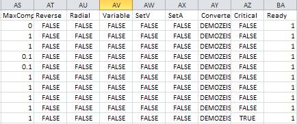
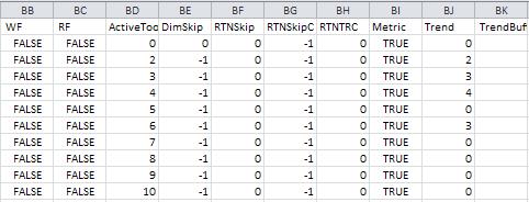
112 108 Working with Run Data
Dostek 440A BTR. Software Guide
 Dostek 440A BTR Software Guide Table of Contents Introduction... 1 Installing Dostek DNC... 1.1 Installing Dostek DNC... 1.2 Installing Your Software License Key... 1.2.1 Install Automatically (Recommended)...
Series 6 Technical Admin Guide Page 1
 Series 6 Technical Admin Guide Page 1 TABLE OF CONTENTS PRODUCT REGISTRATION... 6 Free Trial Registration and the Wizard...7 How the Trial Works...8 Register Invu Document Management...8 Privileges for
USER MANUAL. > analyze. reduce. recover
 USER MANUAL > analyze > reduce > recover Table of Contents COPY AUDIT... 1 OVERVIEW... 1 IMPORTANT NOTES FOR PRINT AUDIT 4 CUSTOMERS... 1 COMMUNICATOR TECHNICAL NOTES... 2 COPY AUDIT SOFTWARE... 2 INSTALLING
Navigator Software User s Manual. User Manual. Navigator Software. Monarch Instrument Rev 0.98 May Page 1 of 17
 User Manual Navigator Software Monarch Instrument Rev 0.98 May 2006 Page 1 of 17 Contents 1. NAVIGATOR SOFTWARE 2. INSTALLATION 3. USING NAVIGATOR SOFTWARE 3.1 STARTING THE PROGRAM 3.2 SYSTEM SET UP 3.3
AEMLog Users Guide. Version 1.01
 AEMLog Users Guide Version 1.01 INTRODUCTION...2 DOCUMENTATION...2 INSTALLING AEMLOG...4 AEMLOG QUICK REFERENCE...5 THE MAIN GRAPH SCREEN...5 MENU COMMANDS...6 File Menu...6 Graph Menu...7 Analysis Menu...8
Console Guide. Version 4.4
 Console Guide Version 4.4 Table of Contents Preface 4 Who Should Use This Guide 4 How This Guide is Organized 4 Document Feedback 4 Document Conventions Used in This Guide 5 Connecting to the Database
StarTeam File Compare/Merge StarTeam File Compare/Merge Help
 StarTeam File Compare/Merge 12.0 StarTeam File Compare/Merge Help Micro Focus 575 Anton Blvd., Suite 510 Costa Mesa, CA 92626 Copyright 2011 Micro Focus IP Development Limited. All Rights Reserved. Portions
MxDS1 CNC Data Shuttle
 MxDS1 CNC Data Shuttle Installation Instructions And Operator Manual 2010 Memex Automation Inc. All rights reserved. No part of this manual may be reproduced without express written consent of Memex Automation
Excel Shortcuts Increasing YOUR Productivity
 Excel Shortcuts Increasing YOUR Productivity CompuHELP Division of Tommy Harrington Enterprises, Inc. tommy@tommyharrington.com https://www.facebook.com/tommyharringtonextremeexcel Excel Shortcuts Increasing
Working with Mailbox Manager
 Working with Mailbox Manager A user guide for Mailbox Manager supporting the Message Storage Server component of the Avaya S3400 Message Server Mailbox Manager Version 5.0 February 2003 Copyright 2003
QUICK START. DevCom2000 User Manual
 QUICK START DevCom2000 uses Device Descriptions (DDs) to access data stored in the memory of the smart field device. These DDs are developed by the manufacturer for their products and, in turn, distributed
Objective 1: Familiarize yourself with basic database terms and definitions. Objective 2: Familiarize yourself with the Access environment.
 Beginning Access 2007 Objective 1: Familiarize yourself with basic database terms and definitions. What is a Database? A Database is simply defined as a collection of related groups of information. Things
Gravimetric Gateway Quick Start Tutorial Manual
 MAGUIRE PRODUCTS INC. GRAVIMETRIC GATEWAY SOFTWARE Gravimetric Gateway Quick Start Tutorial Manual Computer Communications Software for the Maguire Weigh Scale Blenders INSTALLATION OPERATION MAINTENANCE
NiceForm User Guide. English Edition. Rev Euro Plus d.o.o. & Niceware International LLC All rights reserved.
 www.nicelabel.com, info@nicelabel.com English Edition Rev-0910 2009 Euro Plus d.o.o. & Niceware International LLC All rights reserved. www.nicelabel.com Head Office Euro Plus d.o.o. Ulica Lojzeta Hrovata
EXCEL BASICS: MICROSOFT OFFICE 2007
 EXCEL BASICS: MICROSOFT OFFICE 2007 GETTING STARTED PAGE 02 Prerequisites What You Will Learn USING MICROSOFT EXCEL PAGE 03 Opening Microsoft Excel Microsoft Excel Features Keyboard Review Pointer Shapes
OPERATING MANUAL. WINDOWS Temperature Controller. Digi -Sense
 OPERATING MANUAL WINDOWS Temperature Controller Digi -Sense WinTC warranty information and licensing agreement The software and its accompanying documentation and instructions are provided AS IS without
USB Indexer USB Indexer for CNC Controls
 USB Indexer USB Indexer for CNC Controls 2009-2011 Calmotion LLC, All rights reserved Calmotion LLC 9909 Topanga Canyon Blvd. #322 Chatsworth, CA 91311 www.calmotion.com -1 2009-2011Calmotion LLC, All
Data Acquisition with CP-2002/2003 Micro-GC Control
 Varian Analytical Instruments 2700 Mitchell Drive Walnut Creek, CA 94598 Star Chromatography Workstation Version 6 Data Acquisition with CP-2002/2003 Micro-GC Control Operation Manual Varian, Inc. 2002
AEMLog users guide V User Guide - Advanced Engine Management 2205 West 126 th st Hawthorne CA,
 AEMLog users guide V 1.00 User Guide - Advanced Engine Management 2205 West 126 th st Hawthorne CA, 90250 310-484-2322 INTRODUCTION...2 DOCUMENTATION...2 INSTALLING AEMLOG...4 TRANSFERRING DATA TO AND
Rooms Management Manual
 Fidelio Suite 7 Rooms Management Manual Front Office Version 7.13 Creation Date: March 2002 Delphi is a trademark of Borland. MSDOS, Windows 95, Windows-NT and Microsoft Word are trademarks of Microsoft
If your CNC machine memory is full, the PocketDNC gives you more storage, enabling you to store and reload proven programs at a later date.
 Page 1 of 54 Introduction...3 Important! PocketDNC Licence File...3 What s in the Box...4 Setting up Windows Mobile (Win7 Win8 Win10)...5 www.microsoft.com/en-gb/download/details.aspx?id=3182connect Without
HOW TO USE THE EXPORT FEATURE IN LCL
 HOW TO USE THE EXPORT FEATURE IN LCL In LCL go to the Go To menu and select Export. Select the items that you would like to have exported to the file. To select them you will click the item in the left
CCH INCORPORATED 05/03
 Button Bar Main Menu Return to the main tab level of the current library without deselecting your targets Preferences Set preferences for searching, document display, and other functions Citation Search
EXCEL BASICS: MICROSOFT OFFICE 2010
 EXCEL BASICS: MICROSOFT OFFICE 2010 GETTING STARTED PAGE 02 Prerequisites What You Will Learn USING MICROSOFT EXCEL PAGE 03 Opening Microsoft Excel Microsoft Excel Features Keyboard Review Pointer Shapes
User Guide 701P Wide Format Solution Wide Format Scan Service
 User Guide 701P44865 6204 Wide Format Solution Wide Format Scan Service Xerox Corporation Global Knowledge & Language Services 800 Phillips Road Bldg. 845-17S Webster, NY 14580 Copyright 2006 Xerox Corporation.
Parish . User Manual
 Parish Email User Manual Table of Contents LOGGING IN TO PARISH EMAIL... 3 GETTING STARTED... 3 GENERAL OVERVIEW OF THE USER INTERFACE... 3 TERMINATE THE SESSION... 4 EMAIL... 4 MESSAGES LIST... 4 Open
Flip-Q. Version 2.4. Overview
 Flip-Q Version 2.4 Overview Welcome to Flip-Q, a powerful Teleprompter Application that offers must-have features including dual screen support. Dual screen support means that the operator's display is
Authorized Send User s Guide for imagerunner Machines Version 4.1
 Canon Authorized Send User s Guide for imagerunner Machines Version 4.1 08011-41-UD1-003 This page is intentionally left blank. 2 Authorized Send User s Guide for imagerunner Machines Contents Preface...5
Business Process Procedures
 Business Process Procedures 14.40 MICROSOFT EXCEL TIPS Overview These procedures document some helpful hints and tricks while using Microsoft Excel. Key Points This document will explore the following:
RemoteWare OS/2 Client
 RemoteWare OS/2 Client User s Guide Version 4.1 Service Pack 1A RemoteWare OS/2 Client User s Guide Version 4.1 Service Pack 1A This document was prepared to assist licensed users of RemoteWare by XcelleNet,
UTILITY RELOCATION ELECTRONIC DOCUMENT MANAGEMENT SYSTEM (UREDMS)
") UTILITY RELOCATION ELECTRONIC DOCUMENT MANAGEMENT SYSTEM (UREDMS) TRAINING MANUAL EXTERNAL USERS prepared for Commonwealth of Pennsylvania Department of Transportation Bureau of Project Delivery VERSION
UTILITY RELOCATION ELECTRONIC DOCUMENT MANAGEMENT SYSTEM (UREDMS) TRAINING MANUAL EXTERNAL USERS prepared for Commonwealth of Pennsylvania Department of Transportation Bureau of Project Delivery VERSION
Item Number Change for Sage Accpac ERP
 SAGE ACCPAC Sage Accpac Options Item Number Change for Sage Accpac ERP User Guide 2008 Sage Software, Inc. All rights reserved. Sage Software, Sage Software logos, and all Sage Accpac product and service
Copyright 2018 MakeUseOf. All Rights Reserved.
 15 Power User Tips for Tabs in Firefox 57 Quantum Written by Lori Kaufman Published March 2018. Read the original article here: https://www.makeuseof.com/tag/firefox-tabs-tips/ This ebook is the intellectual
Using Expressions Web to Edit an FCNet Department Web Site
 Using Expressions Web to Edit an FCNet Department Web Site Here are the steps to open and edit a site on the new FcWebDept shared department web site server using Microsoft Expression Web 4. The steps
IT Essentials v6.0 Windows 10 Software Labs
 IT Essentials v6.0 Windows 10 Software Labs 5.2.1.7 Install Windows 10... 1 5.2.1.10 Check for Updates in Windows 10... 10 5.2.4.7 Create a Partition in Windows 10... 16 6.1.1.5 Task Manager in Windows
Microsoft Word 2007 on Windows
 1 Microsoft Word 2007 on Windows Word is a very popular text formatting and editing program. It is the standard for writing papers and other documents. This tutorial and quick start guide will help you
2 The Stata user interface
 2 The Stata user interface The windows This chapter introduces the core of Stata s interface: its main windows, its toolbar, its menus, and its dialogs. The five main windows are the Review, Results, Command,
Darca Plus Eltek Download ing And Remote Con trol Applica tion
 Eltek Downloading And Remote Control Application Copyright Microsoft, Windows 98-SE/ME, Windows NT, Windows 2000/XP, Vista, Windows 7 and Excel are registered trademarks of Microsoft Corporation. This
GUARD1 PLUS Documentation. Version TimeKeeping Systems, Inc. GUARD1 PLUS and THE PIPE are registered trademarks
 GUARD1 PLUS Documentation Version 3.02 2000-2005 TimeKeeping Systems, Inc. GUARD1 PLUS and THE PIPE are registered trademarks i of TimeKeeping Systems, Inc. Table of Contents Welcome to Guard1 Plus...
Chapter 12 Creating Tables of Contents, Indexes and Bibliographies
 Writer Guide Chapter 12 Creating Tables of Contents, Indexes and Bibliographies OpenOffice.org Copyright This document is Copyright 2005 by its contributors as listed in the section titled Authors. You
The PeopleSoft Financials System
 The PeopleSoft Financials System 2 Introduction...................... 14 Signing In and Out.................... 14 Signing In to the System.............. 14 Signing Out................... 17 Navigation
CncGcoder Models HD & HDx Manual
 CncGcoder Models HD & HDx Manual Table of Contents WELCOME... 3 IN THE BOX... 4 Optional Accessories...4 HANDHELD OVERVIEW... 5 Overview...5 Charging the Battery...6 Turning On and Off...6 Plugging in
1. Understanding efinanceplus Basics
 1. Understanding efinanceplus Basics To understand the procedures described later in this guide, you will first need some background on the efinanceplus environment. Whether adding, searching for, viewing,
LANCNC FTP LAN network data server for CNC Controls
 FTP LAN network data server for Controls 2008-2009 LLC, All rights reserved LLC 9909 Topanga Canyon Blvd. #322 Chatsworth, CA 91311 www.calmotion.com -1 2008-2009 LLC, All rights reserved Introduction
New Finance Officer & Staff Training
 New Finance Officer & Staff Training Overview MUNIS includes many programs and tools to allow for the management of the District financials. As newer finance officers and staff, you are charged with understanding,
U1000 TOOL COMPENSATION
 1.0 Overview.........2 1.1 Introduction........ 2 1.2 Definitions..........2 1.2.1 Tool Comp Source......2-3 1.2.2 Comper...........4 1.2.3 Trend Reset.........5 1.2.4 Tool Change (TC) Offset.... 5 1.3
User Guide. Rev Dot Origin Ltd.
 User Guide Introduction to the EasyTac File Explorer...1 Using EasyTac to read drivers' cards with a card reader...2 Using EasyTac to read VU files from a download device...3 Using EasyTac to download
Computer Essentials Session 1 Lesson Plan
 Note: Completing the Mouse Tutorial and Mousercise exercise which are available on the Class Resources webpage constitutes the first part of this lesson. ABOUT PROGRAMS AND OPERATING SYSTEMS Any time a
ZENworks 11 Support Pack 4 Endpoint Security Utilities Reference. October 2016
 ZENworks 11 Support Pack 4 Endpoint Security Utilities Reference October 2016 Legal Notice For information about legal notices, trademarks, disclaimers, warranties, export and other use restrictions, U.S.
T205 - SEARCH FOR TRANSLATORS
 dtsearch Desktop/Network Indexing and Search techniques dtsearch Desktop/Network is a powerful search tool used by professionals for a wide variety of tasks, this short tutorial aims to show you how to
PaperClip32. Revision 2.0
 PaperClip32 Quick Start Guide Revision 2.0 Copyright Information Copyright 2003, PaperClip Software, Inc. The PaperClip32 product name and PaperClip Logo are registered trademarks of PaperClip Software,
Allen-Bradley. User Manual. DeviceView Configurator (2707-DNC)
") Allen-Bradley DeviceView Configurator (2707-DNC) User Manual Important User Information Solid state equipment has operational characteristics differing from those of electromechanical equipment. Safety
Allen-Bradley DeviceView Configurator (2707-DNC) User Manual Important User Information Solid state equipment has operational characteristics differing from those of electromechanical equipment. Safety
SEWCAT USER MANUAL V APRIL 14, 2017 S & S COMPUTING Oak Ridge, TN 37830
 SEWCAT USER MANUAL V4.0.6 APRIL 14, 2017 S & S COMPUTING Oak Ridge, TN 37830 Contents 1. Introduction... 3 1.1 Getting Started... 3 1.2 Frequently Asked Questions (FAQ)... 5 1.3 Contact Us... 5 1.4 Purchase
GUARD1 PLUS Manual Version 2.8
 GUARD1 PLUS Manual Version 2.8 2002 TimeKeeping Systems, Inc. GUARD1 PLUS and THE PIPE are registered trademarks of TimeKeeping Systems, Inc. Table of Contents GUARD1 PLUS... 1 Introduction How to get
QST Mobile Application for Android
 QST Mobile Application for Android Welcome This guide will familiarize you with the application, a powerful trading tool developed for your Android. Table of Contents What is this application? Logging
User Manual. Administrator s guide for mass managing VirtueMart products. using. VM Mass Update 1.0
 User Manual Administrator s guide for mass managing VirtueMart products using VM Mass Update 1.0 The ultimate product management solution for VirtueMart! Contents Product Overview... 3 Feature List...
DNC2go
 DNC2go Striker Systems P.O. Box 41 White House, TN 37188 Version 1.0.0.2 www.striker-systems.com Revision 8/2/2005 1 Contents Introduction... 3 Installing DNC2go... 4 Using DNC2go... 5 Setting up a Machine
INST.NO. INE-919. DI5000 Setting Software
 INST.NO. INE919 DI5000 Setting Software Table of contents 1. Introduction... 1 2. System Requirement... 3 21 Operation Condition of the Software... 3 3 How to Setup... 4 31. Installation... 4 311. New
Working with PDF s. To open a recent file on the Start screen, double click on the file name.
 Working with PDF s Acrobat DC Start Screen (Home Tab) When Acrobat opens, the Acrobat Start screen (Home Tab) populates displaying a list of recently opened files. The search feature on the top of the
User Guide. Datgel. Survey Tools gint Add-In
 User Guide Survey Tools gint Add-In DSVT-UG-001-1.04 March 2010 Disclaimer The information in this publication is subject to change without notice and does not represent a commitment on the part of Pty
QuickStart Training Guide: The Accounting Review Role
 Accounting Review Role Final Approval of Expense Reports If you are an Accountant who is using ExpensAble Corporate to make final approval of employees expense reports, this information is for you. This
Getting Started (1.8.7) 9/2/2009
 9/2/2009") 2 Getting Started For the examples in this section, Microsoft Windows and Java will be used. However, much of the information applies to other operating systems and supported languages for which you have
2 Getting Started For the examples in this section, Microsoft Windows and Java will be used. However, much of the information applies to other operating systems and supported languages for which you have
Guide to User Interface 4.3
 Datatel Colleague Guide to User Interface 4.3 Release 18 June 24, 2011 For corrections and clarifications to this manual, see AnswerNet page 1926.37. Guide to User Interface 4.3 All Rights Reserved The
Style Report Enterprise Edition
 INTRODUCTION Style Report Enterprise Edition Welcome to Style Report Enterprise Edition! Style Report is a report design and interactive analysis package that allows you to explore, analyze, monitor, report,
Customization Manager
 Customization Manager Release 2015 Disclaimer This document is provided as-is. Information and views expressed in this document, including URL and other Internet Web site references, may change without
Introduction. Key features and lab exercises to familiarize new users to the Visual environment
 Introduction Key features and lab exercises to familiarize new users to the Visual environment January 1999 CONTENTS KEY FEATURES... 3 Statement Completion Options 3 Auto List Members 3 Auto Type Info
DocumentDirect for the Internet. User s Guide
 DocumentDirect for the Internet User s Guide Copyright 2008-2015 UMB Financial Corporation. (External) Version 3.0 07012015 FINAL July 2015 UMB Reg. U.S. Pat. & Tm. Off. Table of Contents iii Contents
IntelleView /SB Transaction Monitoring System
 IntelleView /SB Transaction Monitoring System Operator's Guide Contents About this Guide... 1 What is IntelleView/SB?... 2 Starting the Operator Application... 3 Video Recording Modes... 6 Viewing Live
Libraries. Multi-Touch. Aero Peek. Sema Foundation 10 Classes 2 nd Exam Review ICT Department 5/22/ Lesson - 15
 10 Classes 2 nd Exam Review Lesson - 15 Introduction Windows 7, previous version of the latest version (Windows 8.1) of Microsoft Windows, was produced for use on personal computers, including home and
Fiery X3eTY2 65C-KM Color Server. Utilities
 Fiery X3eTY2 65C-KM Color Server Utilities 2006 Electronics for Imaging, Inc. The information in this publication is covered under Legal Notices for this product. 45060846 14 November 2006 CONTENTS 3 CONTENTS
Managing Configurations
 CHAPTER 3 The Configurations page is your starting point for managing device configurations for network elements managed by Cisco Prime Network by using the CM tools. The following table lists the main
Getting Started The Outlook Web Access Window
 QUICK Source Microsoft Outlook Web Access in Exchange Server 2003 Getting Started The Outlook Web Access Window ❶ ❷ ❸ ❹ ❺ ❻ ❼ ❽ Using the Reading Pane The Reading Pane allows you to view your e-mail messages
File Cabinet Manager
 Tool Box File Cabinet Manager Java File Cabinet Manager Password Protection Website Statistics Image Tool Image Tool - Resize Image Tool - Crop Image Tool - Transparent Form Processor Manager Form Processor
Navigation Reference Guide
 FISCAL AFFAIRS FINANCIAL MANAGEMENT SYSTEM (FMS) Navigation Reference Guide June 2004 Table of Contents Introduction to Financial Management System... ii Navigation Reference Guide... ii Overview...ii
Newage hardness testing
 Newage hardness testing DataView Data Acquisition Software Operation Manual Version 1.4.3 Newage Testing Instruments, Inc. reserves the right to alter designs, materials, and specifications when conditions
ZENworks 2017 Update 2 Endpoint Security Utilities Reference. February 2018
 ZENworks 2017 Update 2 Endpoint Security Utilities Reference February 2018 Legal Notice For information about legal notices, trademarks, disclaimers, warranties, export and other use restrictions, U.S.
TOSHIBA 3-SERIES DRIVE HANDHELD PROGRAMMER PALM PILOT Software Installation and Operation Manual
 TOSHIBA 3-SERIES DRIVE HANDHELD PROGRAMMER PALM PILOT Software Installation and Operation Manual 3Com Palm IIIx Select File Edit Values Monitor Beam Current File Read From G3 To File Write From File To
Ishida Label Editor USER GUIDE
 Ishida Label Editor USER GUIDE ISHIDA CO., LTD Copyright 2000 Ishida Co. Ltd., Japan Copyright 2000 Interface Translation Ltd., New Zealand No part of this manual may be reproduced or transmitted in any
Colleague UI4.3 Documentation
 Colleague UI4.3 Documentation Table of Contents Getting Started... 2 Add the Shortcuts to your Desktop... 2 Searching for and Using Forms... 3 Begin Your Form Search... 3 Form Search Results... 3 The Navigation
KYOCERA Net Viewer 5.3 User Guide
 KYOCERA Net Viewer. User Guide Legal Notes Unauthorized reproduction of all or part of this guide is prohibited. The information in this guide is subject to change without notice. We cannot be held liable
N2KExtractor. NMEA 2000 Data Extractor Software. User s Manual
 N2KExtractor NMEA 2000 Data Extractor Software User s Manual Revision 1.0.0 Copyright 2012 Maretron, LLP All Rights Reserved Maretron, LLP 9014 N. 23 rd Ave #10 Phoenix, AZ 85021-7850 http://www.maretron.com
.txt - Exporting and Importing. Table of Contents
 .txt - Exporting and Importing Table of Contents Export... 2 Using Add Skip... 3 Delimiter... 3 Other Options... 4 Saving Templates of Options Chosen... 4 Editing Information in the lower Grid... 5 Import...
Welcome to Selector2GO Help
 Welcome to Selector2GO Help World Headquarters 445 Hamilton Avenue, 7th floor, White Plains, New York 10601 United States of America Support: +1 914 259 4900 support@rcsworks.com 2004-2018. All Rights
WaveWare Technologies, Inc. We Deliver Information at the Speed of Light. Enterprise Setup Manual and User Guide
 WaveWare Technologies, Inc. We Deliver Information at the Speed of Light Enterprise Messaging Software Enterprise Setup Manual and User Guide WaveWare Website: www.wirelessmessaging.com Table of Contents
DBT-120 Bluetooth USB Adapter
 DBT-120 Bluetooth USB Adapter Rev.2.1 (09/25/2002) 2 Contents Introduction... 5 Package Contents... 6 Installing Bluetooth Software... 6 Hardware Installation... 8 Introduction to Bluetooth Software...
Tabular Building Template Manager (BTM)
") Tabular Building Template Manager (BTM) User Guide IES Vi rtual Environment Copyright 2015 Integrated Environmental Solutions Limited. All rights reserved. No part of the manual is to be copied or reproduced
Tabular Building Template Manager (BTM) User Guide IES Vi rtual Environment Copyright 2015 Integrated Environmental Solutions Limited. All rights reserved. No part of the manual is to be copied or reproduced
MultiSite Suite: Accounts Payable
 MultiSite Suite: Accounts Payable User s Manual version 6 Copyright & Trademarks Copyright Notice and Trademarks 2010 MultiSite Systems, All rights reserved. Microsoft, Windows, Excel, and Outlook are
CME E-quotes Wireless Application for Android Welcome
 CME E-quotes Wireless Application for Android Welcome This guide will familiarize you with the application, a powerful trading tool developed for your Android. Table of Contents What is this application?
Folder Sync Instruction Manual
 Folder Sync Instruction Manual Document History 4 05-Nov-2011 Updated to reflect notable changes in v1.4.0 3 08-Sep-2011 Updated to reflect notable changes in v1.3.0 2 20-Jun-2011 Updated to reflect notable
Enterprise Architect. User Guide Series. Testing. Author: Sparx Systems. Date: 10/05/2018. Version: 1.0 CREATED WITH
 Enterprise Architect User Guide Series Testing Author: Sparx Systems Date: 10/05/2018 Version: 1.0 CREATED WITH Table of Contents Testing 3 Test Management 4 Create Test Records 6 Working On Test Records
Understanding Word Lesson 1
 Understanding Word Lesson 1 Objectives Software Orientation Before you begin working in Microsoft Word, you need to acquaint yourself with the primary user interface (UI). When you first launch Microsoft
Legal Notes. Regarding Trademarks KYOCERA MITA Corporation
 Legal Notes Unauthorized reproduction of all or part of this guide is prohibited. The information in this guide is subject to change without notice. We cannot be held liable for any problems arising from
Smart Monitor ZG2 User s Manual
 Smart Monitor ZG2 User s Manual Smart Sensors ZG2 Series 2D Profile Measuring Sensors CONTENTS SMART MONITOR ZG2 USER S MANUAL...1 SECTION 1 PREPARATIONS...2 Installing the Smart Monitor ZG2 on a Computer...
UHarvest Slingshot Reports Introduction
 UHarvest Slingshot Reports Introduction UHarvest grain cart data can be saved to a Raven Slingshot account. Use Slingshot to review field reports, edit data, merge multiple job files into one report, and
Vision Express Vision VE810 Installation Guide Vision Engraving & Routing Systems
 Vision Express Vision VE810 Installation Guide Vision Express - Vision VE810 Installation Guide All rights reserved. No parts of this work may be reproduced in any form or by any means - graphic, electronic,
Learning Guide for User Interface 4.3
 Learning Guide for User Interface 4.3 This guide will help you learn how to use Datatel User Interface 4.3. It includes instructions for accomplishing various tasks, such as accessing a screen or mnemonic,
Microsoft Dynamics GP. Extender User s Guide Release 9.0
 Microsoft Dynamics GP Extender User s Guide Release 9.0 Copyright Copyright 2005 Microsoft Corporation. All rights reserved. Complying with all applicable copyright laws is the responsibility of the user.
IDEA. User s Guide. Part No IDE02 Issue 1-0, April 1995 Printed in U.S.A. (183)
") IDEA User s Guide Part No. 17500IDE02 Issue 1-0, April 1995 Printed in U.S.A. (183) 4 FOREST PARKWAY, SHELTON, CONNECTICUT 06484 TEL: 203-926-5400 FAX: 203-929-0535 This manual has been developed by Nitsuko
IDEA User s Guide Part No. 17500IDE02 Issue 1-0, April 1995 Printed in U.S.A. (183) 4 FOREST PARKWAY, SHELTON, CONNECTICUT 06484 TEL: 203-926-5400 FAX: 203-929-0535 This manual has been developed by Nitsuko
Exhibitor Software User s Manual. Exhibitor Software V
 Exhibitor Software User s Manual Exhibitor Software V1.0.1 090908 1 Contents 1. Exhibitor Software 2. Installation 3. Using Exhibitor Program 3.1 Starting the Program 3.2 Logging in to the Program 3.3
Compatibility with graphing calculators 32 Deleting files 34 Backing up device files 35 Working with device screens 36 Capturing device screens 36
 Contents Introduction to the TI Connect Window 1 TI Connect Window 1 Opening the TI Connect Window 2 Closing the TI Connect Window 4 Connecting and disconnecting TI handheld devices 4 Using Task Shortcuts