MXview User s Manual
|
|
|
- Jasmine Clark
- 5 years ago
- Views:
Transcription

1 User s Manual Edition 10.0, March Moxa Inc. All rights reserved.
2 User s Manual The software described in this manual is furnished under a license agreement and may be used only in accordance with the terms of that agreement. Copyright Notice 2016 Moxa Inc. All rights reserved. Trademarks The MOXA logo is a registered trademark of Moxa Inc. All other trademarks or registered marks in this manual belong to their respective manufacturers. Disclaimer Information in this document is subject to change without notice and does not represent a commitment on the part of Moxa. Moxa provides this document as is, without warranty of any kind, either expressed or implied, including, but not limited to, its particular purpose. Moxa reserves the right to make improvements and/or changes to this manual, or to the products and/or the programs described in this manual, at any time. Information provided in this manual is intended to be accurate and reliable. However, Moxa assumes no responsibility for its use, or for any infringements on the rights of third parties that may result from its use. This product might include unintentional technical or typographical errors. Changes are periodically made to the information herein to correct such errors, and these changes are incorporated into new editions of the publication. Technical Support Contact Information Moxa Americas Toll-free: Tel: Fax: Moxa Europe Tel: Fax: Moxa China (Shanghai office) Toll-free: Tel: Fax: Moxa Asia-Pacific Tel: Fax: Moxa India Tel: Fax:
3 Table of Contents 1. Key Features Web-based Operation Auto Discovery and Topology Visualization Event Management Configuration and Firmware Management Traffic Monitoring System Requirements and Supported Devices System Requirements Supported Devices Installation and System Backup Installation Procedure Uninstallation System Backup System Restore Getting Started MXview Server Startup Login Account Auto Installation of Runtime Environment (Java Runtime Environment) Quick Start Using the Setup Wizard Using the Setup Wizard Step 1: Create Group Step 2: Configure the SNMP Community String Step 3: Add the networks you want to scan Step 4: Draw the topology Step 5: Set the SNMP Trap Server to get events in real time Virtual Demo Network Dashboard Overview Menu Bar Topology Map Device List Device Properties List Recent Events List Device Discovery and Polling Changing the Read Community String Scan Range Import/Export Device List Import Device List Export Device List Device Discovery Plug-in Manager for MXview Topology Management Multi-layer Tree Structure Auto Topology and Auto Layout Redundant Topologies PoE Power Consumption Visualization VPN Tunnel Visualization PRP/HSR Visualization Third-Party Icons Port Trunking Add Link Delete Link Delete Device Navigation Background Export Topology OPC Tag Generation Event and Notification Monitoring Methods Monitoring via SNMP Trap Messages Monitoring via Periodic Polling Color Coding Indicates Problems Event Recovery Severity Level Custom Events
4 Recent Events Event History Notification Add an SMS Action Add an Action Add an SNMP Trap Add a Mobile Notification Add a Sound Add an External Program Add a Message Box Syslog Event Network Event Playback Enable Playback Mode Enter Playback Mode Time Mode and Event Mode Overview of Playback User Interface Traffic Reporting Checking the Trend Threshold & Event Notification Device Management Device Properties Device Virtual Panel Changing Device Properties Assign Icon Web Console Login Configuration Backup and Restoration (Moxa devices only) Firmware upgrade Refresh Status Mass Operation Configuration Export/Import and Firmware Upgrade Export Configurations from Multiple Devices Import a Configuration to Multiple Devices Upgrade Firmware on Multiple Devices Scheduled Configuration Export/Import Configuration Change History and Comparison Device and Inventory Report Visualization Mode VLAN Visualization IGMP Snooping Visualization Traffic Load Visualization MIB MIB Browser OID Import Manager Trap Import Manager MXview License Checking the License License Upgrade A. FAQ... A-1 B. License... B-1
5 1. Key 1 Features Moxa MXview network management software gives you a convenient graphical representation of your Ethernet network, and allows you to configure, monitor, and diagnose Moxa networking devices. MXview provides an integrated management platform that can manage Moxa networking devices, such as Ethernet switches and wireless APs, and SNMP-enabled and ICMP-enabled devices installed on subnets. MXview includes an integrated MIB complier that supports any third-party MIB. It also allows you to monitor third-party OIDs and Traps. Network and Trap components that have been located by MXview can be managed via web browsers from both local and remote sites anytime, anywhere. The following topics are covered in this chapter: Web-based Operation Auto Discovery and Topology Visualization Event Management Configuration and Firmware Management Traffic Monitoring
6 Key Features Web-based Operation MXview uses the client-server model. You will need to install the MXview server on a Windows computer connected to the network(s) that are to be managed. After installing MXview, the network can be managed with Internet Explorer or Firefox, without installing additional software. Auto Discovery and Topology Visualization Within the scan range, MXview locates networking devices with SNMP or ICMP services enabled. MXview can collect topology information from devices with LLDP capability and draw the topology of the network, which shows physical connections. For ICMP devices without LLDP, MXview s advanced auto-topology function can verify the connection relationship through ARP algorithms, and help you create an accurate drawing of the network topology. If any managed PoE switches are in your network, the PoE power output information will also be visualized automatically (for more details on PoE visualization, refer to the PoE Power Consumption Visualization section in Chapter 8.) Event Management For troubleshooting purposes, MXview logs events that match preset conditions, such as link up/down, device unreachable, or traffic overloading. The most recent events will show up on the dashboard. Devices and links that generate events will be highlighted with different colors. When an event occurs, users can be notified in a number of different ways, including SMS, , popup window, sound, or external program. Configuration and Firmware Management MXview provides an interface for managing Moxa networking devices from a central location. Users can remotely backup or update configuration files, and upgrade firmware. Traffic Monitoring MXview can log the network traffic of network devices that have been discovered. 1-2
7 2. System 2 Requirements and Supported Devices The following topics are covered in this chapter: System Requirements Supported Devices
8 and Supported Devices System Requirements System Requirements The computer that MXview is installed on must satisfy the following system requirements: CPU RAM Hard Disk Space OS System Requirements 2 GHz or faster dual core CPU 2 GB or higher 10 GB or higher Windows XP Professional, Windows 7 (32/64-bit), Windows 8 (32/64-bit), Windows Server 2008 (32/64-bit), Windows Server 2012 (32/64-bit) Supported Devices MXview supports a full range of functions, such as network status, traffic log, and configuration/firmware file management. For other SNMP-enabled devices, MXview supports standard management functions, such as link up, link down, and SNMP MIBII information. MXview can only monitor the connectivity of devices that support ICMP. 2-2
9 3. Installation 3 and System Backup The following topics are covered in this chapter: Installation Procedure Uninstallation System Backup System Restore

10 Installation and System Backup Installation Procedure 1. Execute the installation program or insert the auto-run CD. 2. During the installation, you can choose the directory in which MXview will be installed and the default language, or leave the settings at the default values. 3. For the commercial version, you will be asked to enter a license key; the license key can be found on a label attached to the protective sleeve of the CD-ROM. 4. After the installation is complete, shortcuts for launching the MXview server will be created on the desktop and in the start menu. Uninstallation 1. Select Start Control Panel, and then select Add or Remove Programs. 2. Select MXview 3. Select Remove You can also uninstall the software by selecting Start All Programs Moxa MXview Uninstall MXview. System Backup To back up the system database and configuration, use Project Database Backup to save the backup files. The Backup startup window will pop up. The system exports the backup database to a directory. Use the following link to open the directory: %MXviewPro_Data%\db_backup Eventually, the Database backup completed event will appear on the Recent Events list. Right-click on the event to show the details, which includes the file path of the backup files. 3-2

11 Installation and System Backup The backup folder uses the following naming convention: YYYYMMDD HHMMSS The items included in the system backup are listed below: Topology Traffic Availability Event Threshold settings Job scheduler settings OID items Trap items System settings System Restore MXview versions 2.2 and higher supports configuration backup files, which use the file extendion *db3. To restore a system configuration from a backup file, first shut down MXview. Then, select the DB Restore tool in Start All Programs Moxa MXview DB Restore tool. Log in using your username and password. Next, identify where the backup files are located: (1) MXview s archive repository, or (2) A custom specific directory. Identify the folder where your backup files are located, and then click Restore. The MXview system will restore the backup files. This process is illustrated step-by-step below: 3-3


12 Installation and System Backup 1. Select Start All Programs Moxa MXview DB Restore tool 2. Login with your username and password 3. Choose the folder where the backup files are located 3-4


13 Installation and System Backup 4. Click Restore MXview versions 2.1 and earlier use *.dat backup files. To restore the system database and configuration from a.dat file, use Project Import MXview Configuration file, and then select the backup file to restore. 3-5
14 4. Getting 4 Started The following topics are covered in this chapter: MXview Server Startup Login Account Auto Installation of Runtime Environment (Java Runtime Environment)
 and a Moxa proprietary protocol that periodically polls")

15 Getting Started MXview is implemented as a web server to realize remote management through a single portal. The following figure illustrates the operational model. The MXview server runs in the background on a Windows PC and communicates with network devices using Simple Network Management Protocol (SNMP) and a Moxa proprietary protocol that periodically polls specific MIB data and stores data in a local database. The MXview client uses web browsers to provide a uniform web interface that enables network operators to access and operate over an intranet or the Internet. MXview Server Startup To start the MXview server, first double-click the MXview desktop shortcut. When the MXview window (shown below) pops up, configure the listening port of the server (or leave it at the default value of 80) and examine the runtime information. The server will launch when you click Start. Clicking Launch Client will start the MXview client on the local computer. To learn how to use the MXview client remotely, refer to the Login section below. NOTE Selecting Connect to MXview with Built-in Browser is recommended. 4-2

16 Getting Started Login To launch the MXview client, open a web browser and input the MXview server s IP address or domain name in the address field. Note that if the server s listening port changes, you will need to input the IP address as follows: If you are using the server computer as the client, you may also click Launch Client on the control panel. The default account is admin. For MXview version 2.6 and earlier, no password is required. For MXview version 2.7 and later, the default password is moxa. NOTE A maximum of 10 users can log in to the system at the same time. NOTE For remote users, downloading "MXviewClient" from the MXview server, and using "MXviewClient" to login are recommended. 4-3

17 Getting Started Account There are 3 default accounts (admin, user and guest) with 2 different authorities (Administrator and User), as shown below. Default User Name Default Password Authority admin moxa Administrator user - User guest - User The "Administrator" can change configurations in MXview, such as topology and scan range. The "User" authority has read-only permission. For MXview version 2.7 and later, accounts can be created, modified and removed and given different authority permissions. NOTE Up to 100 accounts can be created. Auto Installation of Runtime Environment (Java Runtime Environment) The MXview client must run in a JRE environment. For users who do not have the appropriate version of JRE, MXview will guide users to install the appropriate version of JRE automatically. 4-4
18 5. Quick 5 Start Using the Setup Wizard MXview provides a Setup Wizard that can be used to quickly determine the network topology and handle basic configuration tasks. The following topics are covered in this chapter. Using the Setup Wizard Step 1: Create Group Step 2: Configure the SNMP Community String Step 3: Add the networks you want to scan Step 4: Draw the topology Step 5: Set the SNMP Trap Server to get events in real time Virtual Demo Network

19 Quick Start Using the Setup Wizard Using the Setup Wizard The wizard will launch automatically when the software does not contain any nodes. To launch the Setup Wizard manually, select Project Wizard. You should see the following window: The wizard will guide you through five basic steps, described below. Step 1: Create Group Devices scanned by MXview can be organized into a multi-layer tree structure. Before finding devices, groups need to be created. Root is the only default group. All other created groups are placed under the next level of Root. 5-2


20 Quick Start Using the Setup Wizard Step 2: Configure the SNMP Community String MXview uses SNMP to collect device information. The default SNMP configurations are: Version: v1 Read community string: public Write community string: private If necessary, update this information at this time: Step 3: Add the networks you want to scan MXview s operation is based on IP (Internet Protocol). Other devices in the scan range that use IP to operate will be located and monitored. 5-3


21 Quick Start Using the Setup Wizard Click Add Network to add a network range to scan. A window will pop up, with two tabs: Single Range and Multiple Ranges. Single Range: Enter the first and last IP address in the desired range. Name this range in the Name field. Multiple Ranges: The Multiple Ranges tab allows you to set up a complicated subnet for scanning. Select enable for the subnet range, similar to using a subnet mask. You can also name the scan range, as in the Single Range tab. 5-4

22 Quick Start Using the Setup Wizard Another way to scan the network is to Import Device List. Click Import Device List and select a list file to load the devices into MXview. NOTE A device s IP address must be configured properly before it can be managed by MXview. At this point, MXview will enter the discovery stage. The time needed to complete this stage depends on the size of the scan range. Click Cancel at this point to exit the wizard; however, the configurations entered previously will be saved and the discovery process will continue running in the background. 5-5

23 Quick Start Using the Setup Wizard Step 4: Draw the topology After all devices have been located, MXview will be able to draw the topology for LLDP devices. For devices without LLDP functionality, the topology can be drawn manually after the wizard is finished. After all devices have been discovered and the topology has been created, click Next to continue to the next step. 5-6


24 Quick Start Using the Setup Wizard Step 5: Set the SNMP Trap Server to get events in real time To enable real-time event generation, the MXview server s IP address needs to be configured as a trap server. To do this, enter the IP address of the MXview Server and then click Set to activate the change. If this step is skipped, devices can still be monitored by polling periodically, although a time latency will be introduced. After this point, MXview initialization is complete. NOTE For quick troubleshooting in the future, follow the setup wizard to take a snapshot of your network. 5-7


25 Quick Start Using the Setup Wizard Virtual Demo Network MXview provides a virtual demo network that can be used to evaluate many features of MXview. To activate the virtual demo network, run Setup Wizard and select the Start Demo Network option at the bottom of the window. 5-8


26 Quick Start Using the Setup Wizard By following the MXview Setup Wizard, you can easily build up the network environment. After the Setup Wizard is done, you can experience MXview with the virtual demo network. 5-9

27 Quick Start Using the Setup Wizard 5-10

28 6. Dashboard 6 Overview The Dashboard should appear when you log in to MXview. When using MXview, you will spend most of your time working from the Dashboard, which is divided into the following sections: 1. Menu Bar 2. Topology Map 3. Device List 4. Device Properties List 5. Small Scale Topology Map 6. Recent Event List 7. Status Bar The following topics are covered in this chapter: Menu Bar Topology Map Device List Device Properties List Recent Events List
29 Dashboard Overview Menu Bar All operations can be accessed from the following menu bar items: Project Use the Project menu to scan devices with multiple IP ranges, add devices with a specific IP address, maintain network groups, set up MXview preferences, or start the Setup Wizard. Also, you can back up data and configurations of the monitored networks, event history, job schedules, or network topology to a local file, or import a project file to create monitored networks on the fly. View Use the View menu to change the appearance of the Topology Map. For example, you can adjust the resolution or create a topology map. Device Use the Device menu to configure or examine the properties of objects. Link Use the Link menu to delete a link or get traffic reports. Information Use the Information menu to examine network-wide properties. Event Use the Event menu to examine events and set up notifications. Tools Use the Tools menu to launch additional services or programs, such as Moxa IP Configurator. MIB Use the MIB menu to compile or browse for a third party MIB. Import third party OIDs and Traps through the OID import manager and the Trap import manager. Help Use the Help menu to view license information or information about MXview. 6-2

30 Dashboard Overview Topology Map The Topology Map displays connection relationships of monitored devices. For devices with LLDP capability, the connections can be drawn automatically. Device List The Device List shows the Topology Map structure in tree format. Note that link information is not shown. Type all or part of a device name in the Search Devices input box to only show devices whose names contain that keyword (for example, type EDS to show all EDS devices, or type EDS-G509 to show all EDS-G509 switches in the network. 6-3


31 Dashboard Overview Device Properties List The Device Properties list shows the properties of the device that is currently selected. If a device s interface is a PoE port, the icon will change to include a yellow electric charge. Recent Events List This list shows the events that have occurred most recently. Event Count lists the total number of events of different types, with different event types identified by different colored rectangles (e.g., red, yellow, and green, as shown in the following screen shot). All Events is the shortcut of the menu item Event All. When you click All Events, a window will pop up showing all events. 6-4

32 7. Device 7 Discovery and Polling Devices in the assigned scan range can be discovered via SNMP and ICMP protocols. After a device is discovered, MXview will use SNMP and ICMP to poll the device periodically. To configure this function properly, you will need to know the following information: 1. The IP addresses of the devices on the network. 2. The Read community name assigned to the devices on the network. Changing the Read Community String The default Read community string that is used to discover devices is public. Take the following steps to change the value: 1. Select Project Preferences SNMP Configuration. 2. Enter the new Read community string.

33 Device Discovery and Polling Scan Range You can assign multiple scan networks, with each network defined by a starting IP address and an ending IP address. MXview will discover all active devices that belong to the scan networks. Take the following steps to add a scan network: 1. Select Project Scan Range. 2. Click Add Network. 3. Input the starting and ending IP addresses of the range, and then click OK. 4. Click OK & Discovery to start discovery. NOTE Device discovery will require more time for larger networks. For this reason, if possible you should avoid defining large scan ranges. 7-2

34 Device Discovery and Polling Deleting a scan network will remove the monitored devices that belong to the network. Take the following steps to delete a scan network: 1. Select Project Scan Range 2. Select a row in the table Scan Range 3. Click Delete Network 4. Click OK to activate the change Modifying a scan network will remove devices that do not belong to the new network, and discover new devices within the new network. Take the following steps to modify a scan network: 1. Select Project Scan Range 2. Select a row in the table Scan Range 3. Click Modify Network 4. Modify the starting and ending IP address of the range, and then click OK 5. Click OK to activate the change. Deselecting the Active checkbox of a scanned network will stop device discovery for that network. Previously discovered devices will continue to be monitored, with the current status shown on the topology map. Import/Export Device List By using this function, users can easily export any device into a device list, and also can import any device list into MXview. Import Device List 1. Select Project Import Device List 2. Select a list and click Open 3. All the devices in the list are imported into MXview 7-3


35 Device Discovery and Polling Export Device List 1. On the Topology Map, Select the devices which will be exported into the list 2. Select Project Export Device List 3. Enter a file name and click Save 4. The device list is saved NOTE The Device List can be utilized in all the software of MXstudio, including MXconfig, MXview, and N-Snap. Device Discovery MXview will use SNMP and ICMP to discover devices within the scan ranges. When a Moxa device has been located, MXview will use an actual image of the device, such as the one shown here, to indicate the device s location on the network. 7-4
36 Device Discovery and Polling MXview will also list detailed properties and configuration parameters, including the following: MAC address Model name IP address Netmask Gateway Trap server address Auto IP configuration Type of redundancy protocol Role in redundancy protocol Status and properties of the port Status of the power Status and version of the SNMP protocol MXview will use one of the following graphics to indicate devices: Moxa devices with SNMP enabled. Third party devices with SNMP enabled. Third party devices with ICMP enabled. The IP address and location name of the discovered device will be shown under the image of the device. Take the following steps to change the location name: 1. Select the device 2. Select Device Maintenance Configure IP & SNMP 3. Select the Basic tab and then enter the new location name. MXview will run conduct device discovery periodically to find new devices in the scan ranges. You may also use the following steps to conduct device discovery manually: 1. Select project Scan Range 2. Click OK & Run Discovery Discovered devices will be polled periodically by ICMP and SNMP. This is done for the following reasons: 1. To monitor the availability of devices. 2. To update properties and configuration parameters of devices. 3. To update traffic information, such as utilization. 7-5


37 Device Discovery and Polling Plug-in Manager for MXview For Moxa devices without default support by MXview, add the Plug-in Kits of these devices into MXview through the Plug-in Manager, and the devices icons will be shown on the MXview Topology Map. 1. Select MXview Plug-in Manager for MXview in Start menu 2. Enter the username and password which are the same as MXview 3. In Plug-Ins page, click Add and select a Plug-in Kit folder 4. The Plug-in models are shown in the list and successfully added into MXview 5. Exit Plug-in Manager and login MXview, and these models icons can be shown on Topology Map 7-6

38 8. Topology 8 Management The Topology Map is the core of MXview, and can be used to complete most actions. The Topology Map shows a graphical representation of the devices in your networks, and can be used to do the following: Display a graphical representation of a real network. Show connecting relationships between devices. Indicate the status of devices and links. Multi-layer Tree Structure The Topology Map can be organized into a multi-layer tree structure of up to 5 layers. It helps users manage a large number of nodes on the computer screen. For example, users can move nodes of the same subnet or location into the same group. Root, which is the only one group at the first layer, exists by default and cannot be deleted. Groups created by users are in the layer under Root. Devices can be moved between groups. MXview uses an icon to indicate user-defined groups: The first layer will be shown as: The second layer will be shown as:

39 Topology Management The map is represented as a tabbed window, in which each tab is a group. Double clicking a group icon in Root will open the corresponding tab. Auto Topology and Auto Layout For devices with LLDP functionality, MXview can draw the physical topology map, down to the port level of the devices. For devices without an LLDP MIB, MXview is able to draw links by using ARP. To activate this function, select the Advanced Topology Analysis checkbox. MXview can do the following two tasks automatically: (1) Create a new topology, and (2) Update the existing topology. Creating a new topology deletes all links, requests LLDP information from devices, and draws topology maps based on the gathered information. 1. Select View Auto Topology 2. Select New Topology 3. Click OK 8-2

40 Topology Management NOTE Links drawn manually will be also deleted by this action. NOTE Your devices must have firmware version 3.1 or higher to use Advanced Topology Analysis. NOTE If the AutoTopology function does not create an accurate representation of the actual network, deselect the Advanced Topology Analysis check box and try again. Updating the existing topology adds new links and updates existing links, but does not change the status of links that are indicated as having been disconnected or links that were drawn manually. 1. Select View Auto Topology 2. Select Update Topology 3. Click OK The following figure shows an example of a topology map: 8-3
41 Topology Management Auto topology supports third-party devices which are compatible with LLDP MIB. Moxa Device* Third-party SNMP Device IP Device Auto Topology LLDP MIB ARP-based auto topology (Moxa switch w/firmware 3.1) LLDP MIB Supported if connected to a Moxa switch. NOTE LLDP is enabled by default on Moxa devices. Please keep LLDP enabled to use the Auto Topology function. Redundant Topologies Redundant topologies have at least one backup link, which will be indicated with a dashed line: For devices that play a particular role in the topology, MXview will label the devices by displaying the roles above the images of the devices. Backup links will be indicated with dotted lines. RSTP has a Root Turbo Ring has a Master Turbo Chain has a Head and a Tail NOTE Only auto topology can draw dashed lines for redundancy links. Manually drawn redundant links will appear as solid lines. 8-4
42 Topology Management PoE Power Consumption Visualization By periodic polling, a PoE link will display the port number, power (watts) voltage (V) and current (ma) directly on the topology map. VPN Tunnel Visualization The VPN tunnel link will be indicated using different colored lines, as shown below. An icon in one of three different colors indicates VPN statuses: Blue: All VPN tunnels are connected Yellow: At least one VPN tunnel is disconnected Red: All VPN tunnels are disconnected NOTE VPN Tunnel Visualization is only available on Moxa s EDR-810 series of secure routers. 8-5
43 Topology Management PRP/HSR Visualization MXview is able to indicate different roles of PRP/HSR technology, including PRP, HSR, Coupling, and Quadbox. The links of PRP/Coupling LAN A, LAN B, and HSR Ring are indicated with different colored lines. NOTE PRP/HSR Visualization is only available with Moxa s PT-G503 series. 8-6

44 Topology Management Third-Party Icons MXview is able to support most network devices, even those made by many different vendors. Below is an example of a network which includes Moxa devices and a Cisco device. MXview will change the device icon to indicate that the device is a Cisco device. Vendors with MXview support includes: ABB, CISCO, Emerson, Hirschmann, Rockwell, Schneider, and Siemens. Port Trunking Port trunking, also called link aggregation, involves grouping links into a link aggregation group. Trunking links will be indicated with thick, solid lines. NOTE Only auto topology can draw thick lines for trunking links. Manually drawn trunking links will appear as solid lines. NOTE For trunked link, check Device Properties to get the port number corresponding to the trunking group. 8-7


45 Topology Management Add Link Use one of the following two options to connect two devices with a link in a topology map: 1. Right click on a device and then select Add Link. 2. Click on a device to select it and then click Link Add Link on the menu bar. 3. Enter the ports and IP addresses corresponding to the link. Use the plus sign at the left bottom corner to add multiple entries at one time. NOTE Trunking and redundancy links added manually will appear as solid lines. NOTE Port numbers must be numeric and entered correctly to obtain the correct traffic information. NOTE For modular switches, a port number depends on the chassis to which the port belongs, but not on how many modules are inserted. For switches such as the PT-7828, the first module s port numbers are from 1 to 8, the second module s port numbers are from 9 to 16, and so on. The port number depends only on which slot the module is in; in other words, the port number is the same regardless of whether other slots are empty or occupied. Delete Link Use the following steps to remove a link in the topology map: 1. Select the link. 2. Right-click the link and select Delete Link, or select Link Delete Link. NOTE Deleting a link will delete a link from the topology map, but it will not affect the actual network configuration. 8-8


46 Topology Management Delete Device You can delete devices from the topology map. After a device is deleted, it will be removed from the topology map and scan range, and the device would not be polled or located when conduction device discovery. Take the following steps to delete a device: 1. Select the device 2. Right-click the device 3. Select Delete Device Deleted devices will be recorded in Project Scan Range. You may recover devices that have been deleted. Once recovered, the devices will be polled and located when conducting device discovery Take the following steps to recover deleted devices: 1. Select Project Scan Range 2. Select a row in table Deleted Devices 3. Click Recover and then click OK Navigation Mini map is a frame with a slider for adjusting the resolution. This function helps users zoom in to enlarge devices or zoom out to view more devices on the screen. 8-9


47 Topology Management Background You may insert a background image into the topology map to provide additional references, such as geographical information or deployment layout. Take the following steps to insert or change a background image: 1. Select View Set Background 2. Choose an image from the local file system. Take the following steps to delete the background image from the topology map: Select View Delete Background Export Topology The topology map can be exported as a JPEG image. Take the following steps to export the topology map: 1. Select View Export Topology 2. Choose the location to which the image is saved. OPC Tag Generation MXview can generate OPC 2.0-compliant tags of device and link properties. OPC clients such as SCADA Systems can access and use these tags. 1. Select Tools OPC Server 2. Click Start 8-10

48 Topology Management Currently, the default information that MXview can prepare as tags includes: 1. A Health tag, which represents the health status of whole network. 2. Device IP address, MAC address, and status, which are labeled beginning with D_. 3. A link's corresponding IP address and ports, which are labeled beginning with L_. NOTE The Health tag represents the health status of the entire network. There are three levels: Normal, Warning, and Critical, with the values 0, 1, and 2 respectively. MXview allows users to use only one tag to monitor the status of the whole network MXview can also transfer all the SNMP properties in Device Properties List to OPC tags. 1. Select Tools Custom OPC Tags 2. Click to manually add properties into list 3. Select properties in the list and click Register to implement them on devices 4. It shows Tag count and Registered device count 5. Click OK and finish transferring 8-11


49 Topology Management If the properties that you want to transfer are not shown in the properties list, you can use the MXview MIB Browser to manually import the MIB files. Then, the OID Import Manager can help import the OIDs into Devices Properties List and they will be easily transferred to OPC tags. In the same way, any third-party proprietary MIB can generate its OPC tag. 8-12

50 Topology Management Example: Retrieving transmission distance though MXview OPC Server To retrieve transmission distance through MXview OPC Server, the first step is load the relative MIB, and import the transmission distance SNMP OID devtxrange into Device Properties List. Then, users can easily find the property in the properties list and transfer it to an OPC tag. 1. Select MIB MIB Browser 2. Select File Load MIB 3. Select the SNMP MIB and add it into the MIB list 4. Select MIB OID Import Manager 5. Click Add and select the specific OID 6. Assign this OID to selected devices 7. The new OID appears in the Devices Properties List 8. The property devtxrange is shown in the properties list and can be transferred to an OPC tag 8-13

51 Topology Management 8-14

52 Topology Management 8-15

53 Topology Management 8-16
54 9. Event 9 and Notification The following topics are covered in this chapter Monitoring Methods Monitoring via SNMP Trap Messages Monitoring via Periodic Polling Color Coding Indicates Problems Event Recovery Severity Level Custom Events Recent Events Event History Notification Add an SMS Action Add an Action Add an SNMP Trap Add a Mobile Notification Add a Sound Add an External Program Add a Message Box Syslog Event Network Event Playback Enable Playback Mode Enter Playback Mode Time Mode and Event Mode Overview of Playback User Interface


55 Event and Notification Monitoring Methods Monitoring can be conducted using SNMP trap messages, periodic SNMP polling, periodic ICMP polling, or color coding, as described in the following subsections. Monitoring via SNMP Trap Messages By using the MXview server as a trap destination of a device, events associated with the device will be sent to the server in real time, and can be seen by remote clients. Take the following steps to set the trap destination of all devices: 1. Select Tools Set Trap Server to All 2. Enter the IP address of the MXview server and the community string. Take the following steps to set the trap destination of one device: 1. Select Device Maintenance Configure IP & Trap 2. Choose tab Trap Server 3. Enter the IP address of the MXview server and community string The event types include port link up/down, power on/off, topology change, and configuration change. Each discovered device will be monitored automatically by trap once its trap destination is configured correctly. 9-2
56 Event and Notification Monitoring via Periodic Polling After a device has been discovered, MXview polls the status of the device s active port periodically. Keep in mind that since trap messages are transmitted by UDP protocol, there is no absolute guarantee that the messages will be received. What periodic polling does is provide a higher level of reliability for monitoring devices. With periodic polling, MXview can passively monitor the device s SNMP service, bandwidth utilization, error packet rate, and collision rate. MXview can also actively monitor device availability through ICMP polling. MXview pings devices every 10 seconds, and calculates average availability in 24 hours. Separate thresholds can be used for bandwidth utilization, error packet rate, and collision rate. Separate thresholds can be used for bandwidth utilization, error packet rate, collision rate, and device availability, respectively. When any of these thresholds are surpassed, the device will indicate that an event has occurred. Color Coding Indicates Problems When a link causes a warning to be issued or a critical event occurs (link down, for example), the color of the corresponding link line will change: When a device causes a warning or a critical event occurs (device failure, for example), the errant device will be indicated with a box with red borders. In addition, the events will be added to the recent events list. Event Recovery Events will be recovered automatically when condition that caused the event is resolved. 9-3

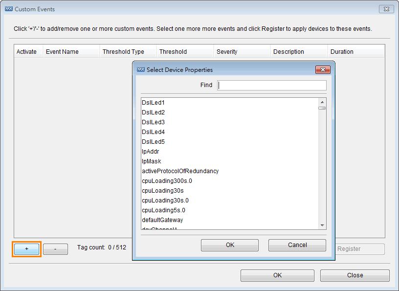
57 Event and Notification Severity Level Events can be set to one of three severity levels: critical, warning, or information. The conditions that give rise to a particular severity level can be configured by the user. To configure the severity levels, select Project Preferences Events, and then modify the settings. Custom Events By using the MXview Custom Events, users can define their own events with flexible thresholds, severity, description, and duration. 1. Select Event Custom Events 2. Click to manually add properties into list 3. Set the Threshold Type, Threshold number, Severity, Description, and Duration 4. Select the properties in the list and click Register to implement them on devices 5. It shows Tag count and Registered device count 6. Click OK and finish setting 9-4

58 Event and Notification 9-5


59 Event and Notification While the events are triggered, they will be shown in the Recent Events List and the related devices will be marked in color. 9-6


60 Event and Notification Once the triggered properties are back to normal status, MXview will show recovery events in the Recent Events List. NOTE The unit of duration is minutes, and only integer values can be set. Recent Events MXview shows recent events at the bottom of the Dashboard. 9-7

61 Event and Notification Event History To show the event history of all devices, select Event All from the menu bar. To show the event history of a single device, right click the device and select Events. The table contains 40 entries on a page. Use the page controls at the bottom to navigate between pages. You can sort the table by clicking the header cells. To filter the table, use the selection box of the header cell and select a value. NOTE The sorting and filtering functions only affect table entries currently showing on the screen. They do not regenerate the entire table. This remains true even if there are currently fewer than 40 entries showing. You can export all events to a CSV file, or delete all events from the database. 9-8

62 Event and Notification Notification You can associate an action, such as send a text message, send an , make a sound, or run an external program, with a combination of a type of event, a source IP address, and a severity level. There are 7 actions: SMS send a SMS text message send an Program run an external program Sound make a sound Message Box show a message box SNMP Trap send a SNMP trap to other SNMP trap server Mobile Client send a push notification to mobile devices There are 19 event types: ICMP unreachable SNMP unreachable Power off Power on Link down Power change to DC Power change to AC Input Bandwidth Utilization over Threshold Input Bandwidth Utilization under Threshold Output Bandwidth Utilization over Threshold Output Bandwidth Utilization under Threshold Input Packet Error Rate over Threshold Output Packet Error Rate over Threshold Device availability under Threshold A custom event is triggered A custom event is recovered Secure router under DDoS attack Secure router firewall under attack Secure router trust access under attack 9-9


63 Event and Notification Add an SMS Action To send an SMS notification, first connect an SMS modem, such as the Moxa Oncell, to an MXview Server COM port. Take the following steps to configure SMS notification: 1. Select Event Notification. 9-10

64 Event and Notification 2. Click Notification Settings. 3. Turn to SMS page. Select the COM port, Baud Rate, and Mode to which the modem is connected, and then click OK. 4. Click New in the Action List. 5. Select SMS as the type, type the phone number, give the action a name, and then click OK. 6. Click New in the Notification List. 7. Select the action just added and the corresponding event type, source IP. 9-11


65 Event and Notification 8. Click OK. Add an Action Take the following steps to configure the (SMTP) server to send an notification: 1. Select Event Notification. 2. Click Notification Settings. 9-12


66 Event and Notification 3. Turn to page. Input the SMTP server that can send an and the user name and password needed to log in to the server, and then click OK. 4. Click New in the Action List. 5. Select as the type, type the address, give the action a name, and then click OK. 6. Click New in the Notification List. 7. Select the action just added and the corresponding event type, source IP. 8. Click OK. Add an SNMP Trap MXview can collaborate with other network management software, and send SNMP Traps to third-party NMSes. MXview supports up to two trap servers. Take the following steps to add an SNMP Trap: 1. Select Event Notification. 2. Click Notification Settings. 9-13

67 Event and Notification 3. Click the SNMP Trap tab. Enter the SNMP version and trap server information, and then click OK. 4. Click New in the Action List. 5. Select SNMP Trap as the Type, give the action a name, and then click OK. 6. Click New in the Notification List. 7. Select the action just added and the corresponding event type, source IP. 8. Click OK. Add a Mobile Notification MXview can send mobile notifications through Apple APNS or Google C2DM with Moxa s mobile APP MXview ToGo. 1. Select Event Notification. 2. Click New in Action List. 3. When the Actions window opens, type in a Name and select Mobile Client as the type. 4. Click Receiver to select an as identification. 5. Click OK. 9-14

68 Event and Notification 6. Click New in Notification List. 7. Type in a Notification Name, select Event Type, enter Source IP, and click the Actions. 8. Click OK. NOTE This function should be used with Moxa s mobile APP MXview ToGo. After setting an as identification in MXview ToGo and connecting to MXview Server, you will be able to find the in the Receiver list. NOTE Using Mobile Notification should give MXview server the capability to connect to Apple APNS or Google C2DM. Please allow the following outgoing ports in your firewall policies: Google: 5228, 5229, and 5230 Apple: 443, 2194, 2195, and 5223 NOTE Use the following commands to review communication between MXview server and Apple APNS or Google C2DM: telnet gcm.googleapis.com 5228 telnet gateway.sandbox.push.apple.com 443 NOTE The Apple APNS certificate should be renewed annually. Please check Moxa s website for latest APNS certificate. Add a Sound When a sound notification is triggered, the MXview server will play the associated sound file. The sound will play repeatedly until some stops it manually. Take the following steps to add a sound: 1. Select Event Notification. 2. Click New in Action List. 3. Select Sound as the type, select a file from the local computer, give the action a name, and then click OK. The file will be uploaded to the MXview server. 9-15

69 Event and Notification 4. Click New in the Notification List. 5. Select the action just added and the corresponding event type, source IP. 6. Click OK. When an associated event occurs, the sound file will be played and a window will pop up: The sound will not stop until someone clicks OK. NOTE When more than one event occurs, the sound file corresponding to the first event will be played first, and the sounds corresponding to subsequent events will be queued. After first sound is stopped, the next sound in the queue will be played. NOTE Only the wav format is supported. Add an External Program When a program notification is triggered, the MXview server will execute the associated program. Take the following steps to add a program: 1. Select Event Notification. 2. Click New in the Action List. 3. Select Program as the type, select a file from the local computer, give the action a name, and then click OK. The file will be uploaded to the MXview server. 4. Click New in the Notification List. 5. Select the action just added, the corresponding event type, and the source IP. 6. Click OK. When an associated event occurs, the program file will be executed. 9-16
70 Event and Notification Add a Message Box When a message box notification is triggered, the MXview server will display the message box. You can create a new message box by following the steps below: 1. Select Event Notification. 2. Click New in the Action List. 3. Select Message Box as the type, give the action a name, and then click OK. 4. Click New in the Notification List. 5. Select the action just added, the corresponding event type, and the source IP. 6. Click OK. When an associated event occurs, the system will show the message box. Syslog Event MXview can act as a Syslog Event Server with Syslog Event Viewer. Take the following steps to use the viewer to check all syslog events: 1. Select Event Syslog Event Viewer 2. Enter Filter Conditions 3. Click Query 9-17

71 Event and Notification Network Event Playback Whenever MXview detects that a device under its management is experiencing an event, such as link down, MXview will update the device status in the topology map. Moreover, MXview will keep records of status changes in a database for up to 30 days, and provides an interface that allows users to go back and check network status from any time within 30 days in a visualized way. Enable Playback Mode The playback mode is disabled by default. To enable it: 1. Select Project Preferences 2. Click System Configuration, choose Enable for Playback 9-18


72 Event and Notification Enter Playback Mode To enter the playback mode, choose Playback as operation mode at the index page. Time Mode and Event Mode There are two event playback modes. In time mode, MXview will replay the event on the topology map on a second-to-second basis. In event mode, MXview will replay event by event. Users can select playback speeds from 1X to 16X. 9-19

73 Event and Notification Overview of Playback User Interface Topology map The topology map displays the network status at the time indicated in the time indicator. Event List and All Event button The events surrounding the current displayed event are displayed in this window. The most recent event is highlighted. Click All Events to access an all events search box, with filters. In the filtered results, you can click on a filtered event to jump straight to that event in the playback. Control pane The control pane includes a time indicator, time slider, and calendar, which correspond to the network currently displayed on the topology map. Users can slide to the time point they would like to check. The slider covers 24 hours in the selected date. To change the date, users can click on the calendar and choose a different date. 9-20

74 10. Traffic 10 Reporting MXview compiles traffic statistics for devices running on the network. The statistics are used to create reports that show trend utilization and performance of the device interfaces. Statistics are complied for the following items: Traffic utilization (%) Error packet rate (%) Events will be generated when one of these items is above or below the corresponding thresholds. Checking the Trend Before MXview can collect traffic statistics between two devices, a link must be created (see the section Adding a Link in chapter 8 to see how to add a link). Right-click on a link, then choose Link Traffic, and choose either Port Traffic or Packet Error Rate monitoring mode. In Port Traffic mode, the graph shows the utilization percentage by a specific time period. You can define your time period at the window s top right corner. The minimum interval is one day.
75 Traffic Reporting The Y-axis scale (percentage) is adjustable, and is accurate to 4 decimal points. To change the Y-axis scale, you just need to roll your mouse wheel down or up. No matter what scale you change it to, you can press the Default Size to restore graph scale back to the original setting. The data shown here can be exported. At the bottom of the window, you can export the graph as a PNG file or export the data as a CSV file. The interface for Packet Error Rate and Port traffic monitoring is identical. Threshold & Event Notification The traffic conditions below can trigger events: 1. Bandwidth utilization is over a threshold. 2. Bandwidth utilization is under a threshold. 3. Packet error rate is over a threshold. Since a link is bidirectional, the event will be triggered when one of the directions satisfies any event s trigger condition. To learn how to change the threshold, refer to Monitoring Methods Color Coding Indicates Problems Severity Level in Chapter 9. To learn how to configure notification, refer to Monitoring Methods Color Coding Indicates Problems Notification in Chapter
76 11. Device 11 Management The following topics are covered in this chapter. Device Properties Device Virtual Panel Changing Device Properties Assign Icon Web Console Login Configuration Backup and Restoration (Moxa devices only) Firmware upgrade Refresh Status Mass Operation Configuration Export/Import and Firmware Upgrade Export Configurations from Multiple Devices Import a Configuration to Multiple Devices Upgrade Firmware on Multiple Devices Scheduled Configuration Export/Import Configuration Change History and Comparison Device and Inventory Report

77 Device Management Device Properties MXview provides three ways to view device properties. 1. Device Property box in main window (see the Device Property List section in chapter 4) 2. Fast Device Property Right click on a device in the main screen and click property. You may select a device and right click on it. Properties that are listed include model name, MAC address, IP address, Netmask, gateway, port type and status, power status, redundancy protocol, SNMP, and ICMP availability. 3. Customizable Device Property In the menu bar, select Information Device Property Device property provides a highly customizable table to view the device properties in your network. On the top of the window, editable optional items include IP, Alias, Property and Value. By selecting the drop-down menu on each option item, you can filter specific items which you wish to display. The property item has the same property as an inventory report (Refer to the section Inventory Report in Chapter 11). As a result, you can use device property to filter out the specific property you want to see. The Device Property window is able to export to a CSV file. To do this, simply click the Export to CSV button. 11-2

78 Device Management Device Virtual Panel MXview can show the front panel of Moxa switches, and indicate the active status of ports and LED indicators: Right click on a device and select Panel Changing Device Properties Take the following steps to change a device s location, name, contact, IP, netmask, gateway, trap server, and SNMP configuration: 1. Select a device. 2. Select Device Maintenance Configure IP & Trap. Click the Basic tab to change the name, location, and contact information for a device. The new values will be written to the device s firmware. Click the IP Configuration tab to change a device s IP address, netmask, gateway, DNS server, and method of obtaining the IP. Click the Trap Server tab to change IP addresses and community strings of trap servers. Moxa switches can send trap messages to at most 2 trap servers. 11-3


79 Device Management Assign Icon MXview allows users to change the device icon manually. Follow the steps below to select a device icon from within MXview s icon database. 1. Select a device. 2. Select Device Maintenance Assign model. You will see the Assign Model window pop up. Select a switch model from the drop-down list, and click the Assign button to confirm your selection. 11-4
 Take the following steps to back up a device s configuration file to a local computer: 1.")
80 Device Management Web Console Login To log in to the device s web console, select Device console. Note: For IE6, MXview will open the console in the window of the MXview Client. Configuration Backup and Restoration (Moxa devices only) Take the following steps to back up a device s configuration file to a local computer: 1. Select Device Maintenance Configuration Load from Device. 2. Choose the location where you would like to save the file. Take the following steps to restore a device s configuration file: 1. Select Device Configuration Load to Device. 2. Choose the file and click OK. Firmware upgrade To up upgrade a device s firmware, select Device Firmware Upgrade. The firmware will be uploaded to and installed on the device. NOTE After the firmware has been installed successfully, the device will restart. This action could take a few seconds. Refresh Status Since some device data is collected by polling, there may be a time delay for some data. To refresh a device to get its updated status, select Device Refresh. 11-5

81 Device Management Mass Operation Configuration Export/Import and Firmware Upgrade MXview lets users export/import configuration and upgrade firmware in a mass deployment to a group of devices. Export Configurations from Multiple Devices 1. Select Tools Configuration Center 2. Click Export from Device 3. Select a folder in which to store configuration files 4. Select devices to export configuration files from and add them to the list. Click Export 11-6

82 Device Management After a few seconds, the configuration files will be exported to the designated folder, with IP addresses and timestamps in the filenames. Import a Configuration to Multiple Devices Moxa switches can import a segment of a configuration file and change device configurations based on the parameters the segment describes. MXview helps users import a segment of a configuration file to multiple devices. 1. Select Tools Configuration Center 2. Click Import to Device 3. Select a configuration file segment 4. Select devices to import configuration files to and add them to the list. Click Import After a few seconds, the configuration file segment will be imported to devices and activated. Upgrade Firmware on Multiple Devices 1. Select Information Firmware Version 2. Click Upgrade 3. Select a firmware file 4. Select devices that upgrade firmware and add to the list. Click Upgrade The firmware will be upgraded to devices one by one. MXview will wait for 30 seconds before upgrading the next device on the list, in order to give the upgrading devices sufficient time to finish the process. 11-7


83 Device Management Scheduled Configuration Export/Import 1. Select Tools Job Scheduler 2. Click Add 3. Enter a job name and select Import Configuration, Export Configuration or Database Backup in the drop-down box. 4. Select the devices that apply and add them to the list. Click Next 5. Select the execution routine. 11-8

84 Device Management Configuration Change History and Comparison When MXview exports configurations from devices, whether manually or by schedule, MXview will compare the exported configuration with the last configuration exported and stored on the MXview server. If there is any difference MXview will save the configuration on the MXview server. Users can then check the change history of the configuration file: 1. Select Tools Configuration Center 2. Check List of Configurations And users can compare any 2 stored configurations at MXview server 1. Select Tools Configuration Center 2. Click Compare 3. Select two IP addresses and their configurations The inserted, deleted and modified lines in the configuration will be highlighted. 11-9

85 Device Management Device and Inventory Report MXview can summarize device information in a formal report. Both a Device Availability Report and Inventory Report are available. Device Availability Report The device availability report includes information about Device IP, Device Alias, Availability average, and Availability worst data. You can narrow the report by a specific time period by dates and groups. Select Information Availability Report 11-10


86 Device Management The availability report can be exported to a PDF or CSV file. By default, the availability is calculated based on 24-hour intervals. To change this, in the menu select Project Preferences Advanced Devices Timeframe for availability calculation Enter the calculation timeframe base in the box and click OK. Units are entered in hours

87 Device Management Inventory Report Select Information Inventory Report to generate an inventory report. Inventory report provides a summary of each device s properties. With Inventory Report, MXview will export reports separately for all the devices in your network. Each device has a single PDF Report. The PDF filename is determined by device IP. The title of the report is the device alias, which you can edit in MXview. If there is any third-party MIB compiled in, the proprietary information will be included into the report (refer to Chapter 13- MIB)
88 12. Visualization 12 Mode The following topics are covered in this chapter. VLAN Visualization IGMP Snooping Visualization Traffic Load Visualization

89 VLAN/IGMP Snooping VLAN Visualization Moxa switches support 802.1Q tagged VLAN. MXview collects each device s VLAN configuration and integrates the information with color-coded visualization to provide a network-wide view. 1. Click the VLAN icon in the topology toolbox. 2. After selecting a specific VLAN ID, devices, ports and links that are associated with the ID will be color-coded. To view the VLAN information in a table format, select Network VLAN IGMP Snooping Visualization Moxa switches support IGMP snooping. MXview collects each device s IGMP snooping configuration and visualizes the information to provide a network-wide view. 1. Click the IGMP icon in the topology toolbox. 2. After selecting a specific VLAN ID and multicast address, devices, ports and links that are associated with the stream will be color-coded. Traffic Load Visualization MXview collects the traffic load information of every link and displays the information to provide users with a network-wide view. 1. Click the Traffic Load icon in the topology toolbox. 12-2


90 VLAN/IGMP Snooping 2. The Traffic Load window pops up. It uses different colors to differentiate between different traffic load levels. 3. All of the links will be color-coded to indicate how much traffic they are carrying. 4. Navigate to Project Preferences Appearance to redefine the traffic load levels. 12-3
91 13. MIB 13 MXview s embedded MIB compiler supports third-party MIB files. After compiling the MIB file, any device s parameter can be monitored in MXview. This chapter covers the following application tools of the MIB compiler: MIB Browser OID Import Manager Trap Import Manager

92 MIB MIB Browser MIB browser provides an easy and comfortable browsing interface for reading proprietary MIB parameters. OID import manager makes all monitored parameters customizable, and they can be read in the device properties window list. With Trap Import Manager, the third-party traps can be displayed in the event history box. MIB Browser is a simple and fast interface that lets you browse MIB files. It is able to load third-party MIB files. After loading the MIB, the OID tree will be listed in the left column. You can unfold these OIDs and get the parameter you need. To open the MIB Browser: Select MIB MIB Browser Click File Load MIB to load a MIB file. Select the item in the MIB tree: Click Get to get the parameter of selected item. Click Get Next to get the OID next to the item you selected. Click Get Subtree to get all the OIDs in the subtree folder. Click Walk to get the OID s parameter in sequence. Click Set to set up parameters of the selected OID. 13-2


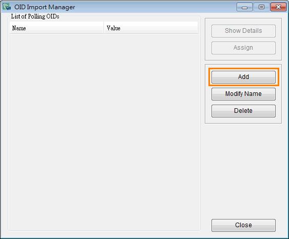
93 MIB OID Import Manager OID Import manager helps to add specific OID items for SNMP polling. It supports third-party MIB with polling. After compiling the MIB files, you can monitor third-party OIDs through SNMP polling. To open the import manager: Select MIB OID Import Manager List of Polling OIDs lists all specific polling items. Click Show Details to see the OID name, OID, and the devices which this OID is assigned to. Click Add to add an OID form the standard MIB or a third party MIB Click Modify to modify an imported OID s name. Click Delete to remove an imported OID There are two steps to add a new OID and assign it to the specific device. 1. Add a specific OID Click Add to add a new OID for polling. A window will pop up. You can import MIB files by selecting File Load MIB. In this window you can edit the Name for the OID you selected. This name will be displayed in the device properties window. Click the Test button to try to get the OID parameter first. You can find the description for this OID in the OID description window. Click the Add button to add this OID into the import manager. 2. Assign polling OID to the device 13-3


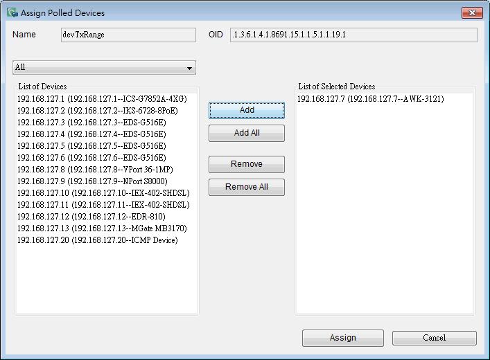
94 MIB Click the Assign button in OID import manager. An Assign Polled Devices window will pop up. This window will list all devices in the network. Select the device you wish to assign then click Add. The selected device will be moved to the right. After selecting the device, click Assign to finish. After adding a device, click the device in the main screen. The third-party MIB OID can be read in the device property window. Trap Import Manager Trap Import Manager can read third-party MIB files, and compile the MIB into MXview. With this tool, MXview can understand traps from third-party MIBs. To open the trap import manager, select MIB Trap Import Manager 13-4

95 MIB The list of traps column will list all the traps which are already imported. Click Show Details to read detailed information, including Trap Name, OID, and its descriptions. Click Import to load MIB files and select the trap to import. Click Modify Description to name the description for the Trap. The description here will be the trap event which shows in the event list. Click Delete to remove an imported Trap. There are three steps to add a new Trap to MXview. 1. Load a MIB Click the Import button. The Import Dialog window will pop up. Then click Load MIB and select a MIB file to load. After the MIB is loaded, click Parse. The column on the right will list all the Traps. 13-5


96 MIB 2. Select Trap to import Select the check box corresponding to the Trap you would like to import. Click the button behind each Trap to show its OID and the original description of its MIB. 3. Edit description In the Trap list, the description field is editable. You are able to write a customized description here. When finished, click the Import button. The dialog will be closed and returned to the Trap Import Manager window. You will find imported Traps in your List. NOTE The system will notify you with a pop-up window if an OID has already been imported. 13-6
97 14. MXview 14 License MXview is available in different versions, which the different versions supporting different numbers of nodes. For example, if your version of MXview supports 250 nodes, then during device discovery MXview will only recognize up to 250 nodes. MXview will stop the device discovery procedure once it reaches the 250-node limit. The MXview license that you purchase specifies the node limit for that version of MXview. To increase the node limit, you can purchase license upgrade and import the upgrade into MXview. Checking the License The number of currently managed nodes and the node limit is shown in the Status Bar on the Dashboard. To check the details, select Help License. License Upgrade To increase the node limit of your MXview, you need upgrade the license. 1. Select Help License. 2. Click Add License.

98 MXview License 3. Find the license label in the software package, which is shown as: 4. Enter the key of the new license and click OK. 5. Restart the MXview client. 14-2
Industrial network management suite for installation, operation, maintenance, and diagnostics. MXview Industrial Network Management Software
 MXstudio Industrial network management suite for installation, operation, maintenance, and diagnostics An all-in-one toolset for installation, operation, maintenance, and diagnostics stages of the network
Moxa Remote Connect Gateway User s Manual
 User s Manual Edition 1.0, December 2017 www.moxa.com/product 2017 Moxa Inc. All rights reserved. User s Manual The software described in this manual is furnished under a license agreement and may be used
Moxa Remote Connect Server Software User s Manual
 User s Manual Edition 1.0, April 2018 www.moxa.com/product 2018 Moxa Inc. All rights reserved. User s Manual The software described in this manual is furnished under a license agreement and may be used
ThingsPro Software User s Manual
 User s Manual Edition 3.0, July 2016 www.moxa.com/product 2016 Moxa Inc. All rights reserved. User s Manual The software described in this manual is furnished under a license agreement and may be used
ThingsPro Software User s Manual
 Edition 2.0, April 2016 www.moxa.com/product 2016 Moxa Inc. All rights reserved. The software described in this manual is furnished under a license agreement and may be used only in accordance with the
SMG-1100/6100 User s Manual
 User s Manual First Edition, January 2011 www.moxa.com/product 2011 Moxa Inc. All rights reserved. Reproduction without permission is prohibited. User s Manual The software described in this manual is
ThingsPro Software User s Manual
 ThingsPro Software User s Manual Edition 1.0, February 2016 www.moxa.com/product 2016 Moxa Inc. All rights reserved. ThingsPro Software User s Manual The software described in this manual is furnished
D-Link Central WiFiManager Configuration Guide
 Table of Contents D-Link Central WiFiManager Configuration Guide Introduction... 3 System Requirements... 3 Access Point Requirement... 3 Latest CWM Modules... 3 Scenario 1 - Basic Setup... 4 1.1. Install
Moxa Managed Ethernet Switch Redundancy Protocol (UI 2.0) User s Manual
 User s Manual") Moxa Managed Ethernet Switch Redundancy Protocol (UI 2.0) User s Manual Edition 4.0, September 2017 www.moxa.com/product Models covered by this manual: EDS-528E, EDS-518E, EDS-510E, EDS-G508E, EDS-G512E,
Moxa Managed Ethernet Switch Redundancy Protocol (UI 2.0) User s Manual Edition 4.0, September 2017 www.moxa.com/product Models covered by this manual: EDS-528E, EDS-518E, EDS-510E, EDS-G508E, EDS-G512E,
Moxa Remote Connect Client Software User s Manual
 User s Manual Edition 1.0, January 2018 www.moxa.com/product 2018 Moxa Inc. All rights reserved. User s Manual The software described in this manual is furnished under a license agreement and may be used
Communication Redundancy User s Manual
 User s Manual Fifth Edition, June 2015 www.moxa.com/product 2015 Moxa Inc. All rights reserved. User s Manual The software described in this manual is furnished under a license agreement and may be used
NMS300 Network Management System Application
 NMS300 Network Management System Application Quick Start Guide October 2013 202-11288-02 350 East Plumeria Drive San Jose, CA 95134 USA Support Thank you for purchasing this NETGEAR product. After installing
Avalanche Remote Control User Guide. Version 4.1
 Avalanche Remote Control User Guide Version 4.1 ii Copyright 2012 by Wavelink Corporation. All rights reserved. Wavelink Corporation 10808 South River Front Parkway, Suite 200 South Jordan, Utah 84095
Viewing System Status, page 404. Backing Up and Restoring a Configuration, page 416. Managing Certificates for Authentication, page 418
 This chapter describes how to maintain the configuration and firmware, reboot or reset the security appliance, manage the security license and digital certificates, and configure other features to help
MX-AOPC UA Server User s Manual
 User s Manual Edition 3.1, November 2016 www.moxa.com/product 2016 Moxa Inc. All rights reserved. User s Manual The software described in this manual is furnished under a license agreement and may be used
Peplink SD Switch User Manual. Published on October 25th, 2018
 Peplink SD Switch User Manual Published on October 25th, 2018 1 Table of Contents Switch Layout 4 Specifications 5 Hardware Overview 6 Quick Start Functions 7 Reset Switch 7 Connect Ethernet 7 Connect
User Manual PDUTracker
 User Manual PDUTracker Management Software for PDU Table of Contents 1. Overview... 1 1.1. Introduction... 1 1.2. Features... 1 2. Install and Uninstall... 1 2.1. System Requirement... 1 2.2. Software
NCOM SERIAL DEVICE SERVER 1XX SERIES USER S MANUAL
 NCOM SERIAL DEVICE SERVER 1XX SERIES USER S MANUAL 2017-07-07 Edition Titan Electronics Inc. Web: www.titan.tw Contents 1. INTRODUCTION... 4 1.1 Key Features... 5 1.2 Specifications... 6 2. PANEL LAYOUT
Industrial Ethernet Products Management Utility
 Industrial Ethernet Products Management Utility Open-Vision User s Manual Version 1.1 April, 2013 ORing Industrial Networking Corp. 3F.,NO.542-2, Jhong-Jheng Rd.Sindian District, New Taipei City 23148
Version /20/2012. User Manual. AP Manager II Lite Business Class Networking
 Version 1.0 12/20/2012 User Manual AP Manager II Lite Business Class Networking Table of Contents Table of Contents Product Overview... 1 Minimum System Requirements... 2 Access Point Requirements... 2
Online Help StruxureWare Data Center Expert
 Online Help StruxureWare Data Center Expert Version 7.2.7 What's New in StruxureWare Data Center Expert 7.2.x Learn more about the new features available in the StruxureWare Data Center Expert 7.2.x release.
Moxa Embedded Switch Module EOM-104 Series User s Manual
 Moxa Embedded Switch Module EOM-104 Series User s Manual Edition 4.0, March 2017 www.moxa.com/product 2017 Moxa Inc. All rights reserved. Moxa Embedded Switch Module EOM-104 Series User s Manual The software
Dell License Manager Version 1.2 User s Guide
 Dell License Manager Version 1.2 User s Guide Notes, Cautions, and Warnings NOTE: A NOTE indicates important information that helps you make better use of your computer. CAUTION: A CAUTION indicates either
NetBrain Technologies Inc. NetBrain Consultant Edition. Quick Start Guide
 NetBrain Technologies Inc. NetBrain Consultant Edition Quick Start Guide Content 1. Install NetBrain Workstation CE System... 3 1.1 Install and Activate NetBrain Gateway Server... 5 1.2 Install Workstation...
Moxa Embedded Switch Module EOM-104 User s Manual.
 Moxa Embedded Switch Module EOM-104 User s Manual www.moxa.com/product First Edition, June 2009 2009 Moxa Inc. All rights reserved. Reproduction without permission is prohibited. The software described
User Guide. Pharos Control Software
 User Guide Pharos Control Software 1910012155 REV 2.0.1 April 2017 COPYRIGHT & TRADEMARKS Specifications are subject to change without notice. is a registered trademark of TP-Link Technologies Co., Ltd.
Moxa EDS-SNMP OPC Server Pro User s Manual.
 Moxa EDS-SNMP OPC Server Pro User s Manual www.moxa.com/product Second Edition, June 2008 2008 Moxa Inc., all rights reserved. Reproduction without permission is prohibited. Moxa EDS-SNMP OPC Server Pro
MX-AOPC UA Server User s Manual
 User s Manual Edition 3.3, February 2018 www.moxa.com/product 2018 Moxa Inc. All rights reserved. User s Manual The software described in this manual is furnished under a license agreement and may be used
Installation Guide. EventTracker Enterprise. Install Guide Centre Park Drive Publication Date: Aug 03, U.S. Toll Free:
 EventTracker Enterprise Install Guide 8815 Centre Park Drive Publication Date: Aug 03, 2010 Columbia MD 21045 U.S. Toll Free: 877.333.1433 Abstract The purpose of this document is to help users install
 Trend Micro Incorporated reserves the right to make changes to this document and to the products described herein without notice. Before installing and using the product, please review the readme files,
Management Software. SmartView TM EMS (Element Management System) Management Software. Management Software SmartView TM EMS. Polled Network Elements
 Management Software. Management Software SmartView TM EMS. Polled Network Elements") LAN PWR PWR 2 PoE Fault Fiber 00 LAN ON OFF Force Auto 0 00 Half Full LFP Flow Pass SW TX RX Ethernet Media Converter FIBER LAN PWR PWR 2 Fault Fiber 00 LAN ON OFF Force Auto 0 00 Half Full LFP Flow Pass
LAN PWR PWR 2 PoE Fault Fiber 00 LAN ON OFF Force Auto 0 00 Half Full LFP Flow Pass SW TX RX Ethernet Media Converter FIBER LAN PWR PWR 2 Fault Fiber 00 LAN ON OFF Force Auto 0 00 Half Full LFP Flow Pass
Quick Start Guide. Get started in 5 minutes! This document will give a brief introduction about the product and its installation procedure.
 Quick Start Guide Get started in 5 minutes! This document will give a brief introduction about the product and its installation procedure. INTRODUCTION The role of a Network Administrator is to manage
SmartView EMS. Central EMS. SmartConfig. Fault, Configuration, Accounting, Performance & Security Management (FCAPS)
") SmartView EMS TM Fault, Configuration, Accounting, Performance & Security Management (FCAPS) Central EMS Expand EMS platform up to 50 SmartViewTM and 25,000 devices management SmartConfig TM Tool for quick
SmartView EMS TM Fault, Configuration, Accounting, Performance & Security Management (FCAPS) Central EMS Expand EMS platform up to 50 SmartViewTM and 25,000 devices management SmartConfig TM Tool for quick
MPC-2120 Windows Embedded Standard 7 User s Manual
 MPC-2120 Windows Embedded Standard 7 User s Manual Edition 1.0, December 2017 www.moxa.com/product 2017 Moxa Inc. All rights reserved. MPC-2120 Windows Embedded Standard 7 User s Manual The software described
SolarWinds Engineer s Toolset Fast Fixes to Network Issues
 DATASHEET SolarWinds Engineer s Toolset Fast Fixes to Network Issues SolarWinds Engineer s Toolset (ETS) helps you monitor and troubleshoot your network with the most trusted tools in network management.
Barracuda Link Balancer
 Barracuda Networks Technical Documentation Barracuda Link Balancer Administrator s Guide Version 2.3 RECLAIM YOUR NETWORK Copyright Notice Copyright 2004-2011, Barracuda Networks www.barracuda.com v2.3-111215-01-1215
SC-T35/SC-T45/SC-T46/SC-T47 ViewSonic Device Manager User Guide
 SC-T35/SC-T45/SC-T46/SC-T47 ViewSonic Device Manager User Guide Copyright and Trademark Statements 2014 ViewSonic Computer Corp. All rights reserved. This document contains proprietary information that
User s Manual. Version 5
 User s Manual Version 5 Copyright 2017 Safeway. All rights reserved. No part of this publication may be reproduced, transmitted, transcribed, stored in a retrieval system, or translated into any language,
Central Management Software. Cam Viewer 3 Lite. User Manual
 Central Management Software Cam Viewer 3 Lite User Manual Version 1.0.0 Table of Contents 1. System Requirement...4 2. Software Installation...5 3. Configuration Wizard...9 3.1 Channel...10 3.1.1 Adding
NVMS User Manual
 NVMS-1000 User Manual Contents 1 Software Introduction...1 1.1 Summary... 1 1.2 Operation Environment... 1 1.3 Install and Uninstall... 2 1.3.1 Install the Software... 2 1.3.2 Uninstall the Software...
CREE SMARTCAST PoE TECHNOLOGY. 68% Current Savings $ SMARTCAST MANAGER USER MANUAL VERSION: Health ADVANCED. 30 Days 30 Hours 30 Min.
 68% Current Savings Occupancy Task Tuning Dimming Daylight Fixture Savings 900 kwh Usage 30 Days 30 Hours 30 Min. 800 kwh 700 kwh Usage Baseline 827kWh Savings 600 kwh 500 kwh 400 kwh 300 kwh 489 kwh 30
SLS-ENVR2016 Network Video Recorder V2.2.2 Quick Setup Guide
 SLS-ENVR2016 Network Video Recorder V2.2.2 Quick Setup Guide The SLS-ENVR2016 series NVR is an intelligent and compact appliance that provides a network interface to monitor, record and playback video
UPort 2000 Series User s Manual
 User s Manual Second Edition, December 2012 www.moxa.com/product 2012 Moxa Inc. All rights reserved. User s Manual The software described in this manual is furnished under a license agreement and may be
Version No. Build Date No./ Release Date. Supported OS Apply to Models New Features/Enhancements. Bugs Fixed/Changes
 Build Date / 4.1 Build_17031311 EDR-G903 3.6 Build_16081017 EDR-G903 1. Compliance to IEC 62443-4-2 level 2 requirement. 2. Support for ifadminstatus MIB information as device s port setting. 3. Support
 Trend Micro Incorporated reserves the right to make changes to this document and to the products described herein without notice. Before installing and using the product, please review the readme files,
Configure Controller and AP Settings
 Configure SNMP Credentials for Rogue AP Tracing, on page 1 Configure Protocols for CLI Sessions, on page 2 Enable Unified AP Ping Reachability Settings on the Prime Infrastructure, on page 2 Refresh Controllers
Network Management Utility
 4343-7705-02 Network Management Utility Foreword Welcome Network Management Utility is utility software that provides central control over printers, copiers, and other devices on a network. With Network
Introduction Of. WebAccess/NMS. ICG AE John Huang
 Introduction Of WebAccess/NMS ICG AE John Huang Agenda Introduction for WebAccess/NMS System Architecture WebAccess/NMS Key Features V1.2.4 new functions Installation & Configuration FAQ PS: If you have
Cisco Unified Serviceability
 Cisco Unified Serviceability Introduction, page 1 Installation, page 5 Introduction This document uses the following abbreviations to identify administration differences for these Cisco products: Unified
Kaseya 2. Quick Start Guide. for Network Monitor 4.1
 Kaseya 2 Router Monitor Quick Start Guide for Network Monitor 4.1 June 5, 2012 About Kaseya Kaseya is a global provider of IT automation software for IT Solution Providers and Public and Private Sector
NCOM SERIAL DEVICE SERVER 4XX SERIES USER S MANUAL
 NCOM SERIAL DEVICE SERVER 4XX SERIES USER S MANUAL 2017-07-07 Edition Titan Electronics Inc. Web: www.titan.tw Contents 1. INTRODUCTION... 4 1.1 Key Features... 5 1.2 Specifications... 6 2. PANEL LAYOUT
Industrial HiVision Quick Start Guide
 Industrial HiVision Quick Start Guide v1.0 August 2011 1 Contents INTRODUCTION...3 INSTALLATION...4 GETTING STARTED...13 NETWORK HIERARCHY...17 DEVICE DISCOVERY...28 TOPOLOGY DISCOVERY...39 STATUS DISPLAY...48
Deployment Guide Installing WhatsUp Gold Distributed Edition to Central and Remote Sites
 Deployment Guide Installing WhatsUp Gold Distributed Edition to Central and Remote Sites This guide provides information about installing and configuring WhatsUp Gold Central and Remote Sites. Contents
Dell EMC OpenManage Mobile. Version User s Guide (Android)
") Dell EMC OpenManage Mobile Version 2.0.20 User s Guide (Android) Notes, cautions, and warnings NOTE: A NOTE indicates important information that helps you make better use of your product. CAUTION: A CAUTION
Dell EMC OpenManage Mobile Version 2.0.20 User s Guide (Android) Notes, cautions, and warnings NOTE: A NOTE indicates important information that helps you make better use of your product. CAUTION: A CAUTION
This guide details the deployment and initial configuration necessary to maximize the value of JetAdvantage Insights.
 HP JetAdvantage Insights Deployment Guide This guide details the deployment and initial configuration necessary to maximize the value of JetAdvantage Insights. 1. Overview HP JetAdvantage Insights provides
IP Device Search and Configuration Tool Operation Manual
 IP Device Search and Configuration Tool Operation Manual Note Copyright Statement This manual may not be reproduced in any form or by any means used to create any derivative such as translation, transformation,
InfraSuite Device Master
 Delta Electronics, Inc. InfraSuite Device Master User s Manual Model: EMS4000 Doc. Version: v1.0 Content 1. Introduction... 5 1.1 System Architecture... 5 2. Software Installation... 7 2.1 Presentation
KYOCERA Net Viewer User Guide
 KYOCERA Net Viewer User Guide Legal Notes Unauthorized reproduction of all or part of this guide is prohibited. The information in this guide is subject to change without notice. We cannot be held liable
IT Essentials v6.0 Windows 10 Software Labs
 IT Essentials v6.0 Windows 10 Software Labs 5.2.1.7 Install Windows 10... 1 5.2.1.10 Check for Updates in Windows 10... 10 5.2.4.7 Create a Partition in Windows 10... 16 6.1.1.5 Task Manager in Windows
Moxa CLI Configuration Tool User s Manual
 User s Manual Edition 1.0, March 2018 www.moxa.com/product 2018 Moxa Inc. All rights reserved. User s Manual The software described in this manual is furnished under a license agreement and may be used
DIGIOP ELEMENTS V8.7 NVR Software-only Installation Guide
 DIGIOP ELEMENTS V8.7 NVR Software-only Installation Guide About this installation guide Use this document as a guide to install your DIGIOP ELEMENTS NVR software system. It includes procedures to install
User Manual. AC ac Wireless Access Point/Router. Model WAC124. NETGEAR, Inc.
 AC2000 802.11ac Wireless Access Point/Router Model WAC124 December 2018 202-11885-02 NETGEAR, Inc. 350 E. Plumeria Drive San Jose, CA 95134, USA AC2000 802.11ac Support Thank you for purchasing this NETGEAR
KYOCERA Net Viewer 5.3 User Guide
 KYOCERA Net Viewer. User Guide Legal Notes Unauthorized reproduction of all or part of this guide is prohibited. The information in this guide is subject to change without notice. We cannot be held liable
Dell EMC License Manager Version 1.5 User's Guide
 Dell EMC License Manager Version 1.5 User's Guide Notes, cautions, and warnings NOTE: A NOTE indicates important information that helps you make better use of your product. CAUTION: A CAUTION indicates
MPC-2070 Windows Embedded Standard 7 User s Manual
 MPC-2070 Windows Embedded Standard 7 User s Manual Edition 1.0, July 2017 www.moxa.com/product 2017 Moxa Inc. All rights reserved. MPC-2070 Windows Embedded Standard 7 User s Manual The software described
 Trend Micro Incorporated reserves the right to make changes to this document and to the products described herein without notice. Before installing and using the product, please review the readme files,
Comodo Network Center Software Version 1.1
 Comodo Network Center Software Version 1.1 User Guide Guide Version 2.3.112311 Comodo Security Solutions 1255 Broad Street STE 100 Clifton, NJ 07013 Table of Contents Comodo Network Center - Introduction...
SLS-ENVR16 Network Video Recorder V2.1.5 Quick Setup Guide
 SLS-ENVR16 Network Video Recorder V2.1.5 Quick Setup Guide The SLS-ENVR16 series NVR is an intelligent and compact appliance that provides a network interface to monitor, record and playback video from
ProSAFE 8-Port and 16-Port 10-Gigabit Ethernet Web Managed Switch Models XS708Ev2 and XS716E User Manual
 ProSAFE 8-Port and 16-Port 10-Gigabit Ethernet Web Managed Switch Models XS708Ev2 and XS716E User Manual March 2017 202-11656-03 350 East Plumeria Drive San Jose, CA 95134 USA Support Thank you for purchasing
Aspera Connect Windows XP, 2003, Vista, 2008, 7. Document Version: 1
 Aspera Connect 2.6.3 Windows XP, 2003, Vista, 2008, 7 Document Version: 1 2 Contents Contents Introduction... 3 Setting Up... 4 Upgrading from a Previous Version...4 Installation... 4 Set Up Network Environment...
D-View 7 Software Release Notes
 Server Version: V1.3.0.7 Probe Version: V1.0.6.0 Published: 2017/08/18 These release notes include important information about D-Link D-View 7 Network Management Software. Please verify that these release
HP Intelligent Management Center Remote Site Manager
 HP Intelligent Management Center Remote Site Manager Administrator Guide Abstract This guide contains comprehensive information for network administrators, engineers, and operators who manage the IMC Remote
SINEMA Server SIMATIC NET. SINEMA Server. Introduction 1. Description. Installing the software 3. Software user interface 4.
 Introduction 1 Description 2 SIMATIC NET Configuration Manual Installing the software 3 Software user interface 4 Configuration 5 Viewing data using an OPC server 6 Quick Links 7 Help 8 FAQs 9 06/2011
USER MANUAL. PowerFrame TM Personal. UPS Monitoring Software
 USER MANUAL PowerFrame TM Personal UPS Monitoring Software www.bxterra.com 1 TABLE OF CONTENTS Introduction... Structure... Applications... Features... System Requirements... Supported Operating Systems...
Wireless USB Port Multi-Functional Printer Server. Model # AMPS240W. User s Manual. Ver. 1A
 Wireless USB 2.0 1-Port Multi-Functional Printer Server Model # AMPS240W User s Manual Ver. 1A Table of Contents 1 Introduction...3 1.1 Package Contents... 3 1.2 System Requirements... 3 2 Multi-Functional
DA-720 Series Windows Software User s Manual
 DA-720 Series Windows Software User s Manual Edition 1.0, January 2017 www.moxa.com/product 2017 Moxa Inc. All rights reserved. DA-720 Series Windows Software User s Manual The software described in this
IP Camera. User Manual
 501583 IP Camera User Manual Version: 1.2 Released Date: June., 2005 Contents 1. Introduction... 3 2. Package Content... 3 3. System Requirement... 3 4. Hardware Installation... 4 4.1. LED and Focusing...4
ForeScout CounterACT Resiliency Solutions
 ForeScout CounterACT Resiliency Solutions User Guide CounterACT Version 7.0.0 About CounterACT Resiliency Solutions Table of Contents About CounterACT Resiliency Solutions... 5 Comparison of Resiliency
PIVOT CMS CLIENT SOFTWARE USER MANUAL
 PIVOT CMS CLIENT SOFTWARE USER MANUAL 1 CMS USER GUIDE 1.1 PC REQUIREMENT Recommended PC Requirement OS CPU VGA RAM HDD Graphics Card OS CPU VGA RAM HDD Windows Vista, 7 or higher Intel Core2Quad Q9400
CLIQ Web Manager. User Manual. The global leader in door opening solutions V 6.1
 CLIQ Web Manager User Manual V 6.1 The global leader in door opening solutions Program version: 6.1 Document number: ST-003478 Date published: 2016-03-31 Language: en-gb Table of contents 1 Overview...9
IsItUp Quick Start Manual
 IsItUp - When you need to know the status of your network Taro Software Inc. Website: www.tarosoft.com Telephone: 703-405-4697 Postal address: 8829 110th Lane, Seminole Fl, 33772 Electronic mail: Contact1@tarosoft.com
NetBrain POC Walk-Through
 NetBrain POC Walk-Through For OE 4.1 Dynamic Documentation Visual Troubleshooting NetBrain Technologies, Inc. 2004-2013. All rights reserved +1.800.605.7964 support@netbraintech.com www.netbraintech.com
ProSAFE 8-Port 10-Gigabit Web Managed Switch Model XS708Ev2 User Manual
 ProSAFE 8-Port 10-Gigabit Web Managed Switch Model XS708Ev2 User Manual April 2016 202-11656-01 350 East Plumeria Drive San Jose, CA 95134 USA Support Thank you for purchasing this NETGEAR product. You
WhatsUp Gold. Evaluation Guide
 WhatsUp Gold Evaluation Guide Table of Contents This guide provides and overview of WhatsUp Gold. Refer to our Online Help for more details. Section Step 1: Getting Started Description Installation requirements
Administration Utilities
 NN47226-600 Document status: Standard Document version: 0301 Document date: 27 April 2010 All Rights Reserved Sourced in Canada and the United States of America The information in this document is subject
Legal Notes. Regarding Trademarks KYOCERA MITA Corporation
 Legal Notes Unauthorized reproduction of all or part of this guide is prohibited. The information in this guide is subject to change without notice. We cannot be held liable for any problems arising from
DBT-120 Bluetooth USB Adapter
 DBT-120 Bluetooth USB Adapter Rev.2.1 (09/25/2002) 2 Contents Introduction... 5 Package Contents... 6 Installing Bluetooth Software... 6 Hardware Installation... 8 Introduction to Bluetooth Software...
Password: admin DW-BJCUBE2T-LX DW-BJCUBE4T-LX DW-BJCUBE6T-LX DW-BJCUBE9T-LX DW-BJCUBE12T-LX DW-BJCUBE18T-LX
 Quick Start Guide State of the art hyper-optimized video management platform designed for ease, speed and efficiency. Blackjack Cube Up to 16 (Cube-LX) and 64 (Cube) 2.1MP Cameras (1080p True HD Resolution)
Operating Manual. Version 7.3.4
 Operating Manual Version 7.3.4 March 2011 Index Page 1. Installation instructions 4 1.1 System requirements 4 1.2 Installation procedure 4 1.3 Meitav-tec USB adaptor installation 7 2. Open Maxinet and
VIP-102B IP Solutions Setup Tool Reference Manual
 VIP-102B IP Solutions Setup Tool Reference Manual Version 6.3.0.0 For latest updates to this manual please check our website at: http://www.valcom.com/vipsetuptool/default.htm then click on Reference Manual
Silver Peak EC-V and Microsoft Azure Deployment Guide
 Silver Peak EC-V and Microsoft Azure Deployment Guide How to deploy an EC-V in Microsoft Azure 201422-001 Rev. A September 2018 2 Table of Contents Table of Contents 3 Copyright and Trademarks 5 Support
Version 4.1 June Xerox Device Agent (XDA) Lite User Guide
 Lite User Guide") Version 4.1 June 2013 Xerox Device Agent (XDA) Lite User Guide 2008-2013 Xerox Corporation. All rights reserved. Xerox and Xerox and Design are trademarks of Xerox Corporation in the US and/or other countries.
Version 4.1 June 2013 Xerox Device Agent (XDA) Lite User Guide 2008-2013 Xerox Corporation. All rights reserved. Xerox and Xerox and Design are trademarks of Xerox Corporation in the US and/or other countries.
Layer 3 Routing (UI 2.0) User s Manual
 User s Manual") User s Manual Edition 3.3, November 2018 www.moxa.com/product Models covered by this manual: IKS-G6824A, ICS-G7826A, ICS-G7828A, ICS-G7848A, ICS-G7850A, ICS-G7852A, PT-G7828 Series 2018 Moxa Inc. All rights
User s Manual Edition 3.3, November 2018 www.moxa.com/product Models covered by this manual: IKS-G6824A, ICS-G7826A, ICS-G7828A, ICS-G7848A, ICS-G7850A, ICS-G7852A, PT-G7828 Series 2018 Moxa Inc. All rights
GIGABYTE Remote Management Console User s Guide. Version: 1.0
 GIGABYTE Remote Management Console User s Guide Version: 1.0 Table of Contents Using Your GIGABYTE Remote Management Console...2 Software Install...3 Prerequisites on remote management PC...3 Install Java
Getting Started with Locator
 Getting Started with Locator The Locator application is a search tool within OmniVista. Locator's Search tab enables you to locate the switch and slot/port that is directly connected to a user-specified
NetBrain OE System Quick Start Guide
 NetBrain Technologies Inc. NetBrain OE System Quick Start Guide For Operator Edition Administrators Table of Contents 1. Install NetBrain OE System... 3 1.1 Install Gateway Server... 4 1.2 Install Network
IBM FlashSystem 720 & FlashSystem 820 Remote Support Overview
 IBM FlashSystem 720 & FlashSystem 820 Remote Support Overview Copyright IBM Corporation 2014 i Applicable Products Product: IBM FlashSystem 720 Product Version(s): 6.3.1-p10, 6.3.0 Product: IBM FlashSystem
SLS-ENVR16 Network Video Recorder V2.1 Quick Setup Guide
 SLS-ENVR16 Network Video Recorder V2.1 Quick Setup Guide The SLS-ENVR16 series NVR is an intelligent and compact appliance that provides a network interface to monitor, record and playback video from up
vrealize Operations Management Pack for NSX for vsphere 2.0
 vrealize Operations Management Pack for NSX for vsphere 2.0 This document supports the version of each product listed and supports all subsequent versions until the document is replaced by a new edition.