Shape optimisation using breakthrough technologies
|
|
|
- Dana O’Neal’
- 5 years ago
- Views:
Transcription


1 Shape optimisation using breakthrough technologies Compiled by Mike Slack Ansys Technical Services 2010 ANSYS, Inc. All rights reserved. 1 ANSYS, Inc. Proprietary
2 Introduction Shape optimisation technologies ( Automated Invention? ) 2010 ANSYS, Inc. All rights reserved. 2 ANSYS, Inc. Proprietary
3 Fast and Reliable Design Objective: Introduce two New and Elegant CFD shape optimisation methods. Do my best to describe how they work. Explain how these can reliably reduce your simulation time to find a shape optimised design ANSYS, Inc. All rights reserved. 3 ANSYS, Inc. Proprietary
4 Optimizsation The process of adjusting control variables to find the levels that achieve the best possible outcome. The challenge is to achieve optimisation efficiently CFD runs can be long and expensive, even IO can be significant. So we will consider systematic methods to find an optimum response with a few trials Consider the different choice of technology, approach and algorithm? 2010 ANSYS, Inc. All rights reserved. 4 ANSYS, Inc. Proprietary
5 Fast and Reliable Design The tools that will be presented are all available in the current release. The Mesh Morph Optimiser is our first full release of this technology type. The adjoint concept has been 10 years in the making and is a unique offering in commercial CFD. At this point the functionality is still Beta ANSYS, Inc. All rights reserved. 5 ANSYS, Inc. Proprietary
6 Agenda 1. Introduction 2. Morphing 3. Linear shape optimisation methods 4. Derivative based optimisation method 5. Summary 2010 ANSYS, Inc. All rights reserved. 6 ANSYS, Inc. Proprietary
7 Morphing 2010 ANSYS, Inc. All rights reserved. 7 ANSYS, Inc. Proprietary
8 Mesh Morphing Applies a geometric design change directly in the solver? Uses a Bernstein polynomial-based morphing scheme Freeform mesh deformation defined on a matrix of control points leads to a smooth deformation User prescribes the scale and direction of deformations to control points distributed evenly through the rectilinear region ANSYS, Inc. All rights reserved. 8 ANSYS, Inc. Proprietary

9 Morpher Usage is based on the system of control points that can be moved freely in space 2010 ANSYS, Inc. All rights reserved. 9 ANSYS, Inc. Proprietary

10 Morpher Deformation based on movement of one control point 2010 ANSYS, Inc. All rights reserved. 10 ANSYS, Inc. Proprietary

11 Morpher Deformation can be performed many times 2010 ANSYS, Inc. All rights reserved. 11 ANSYS, Inc. Proprietary
 2010 ANSYS, Inc. All rights reserved. 12 ANSYS, Inc.")
12 Morpher Deformation volume can have different numbers of control points (example now uses five by two points) 2010 ANSYS, Inc. All rights reserved. 12 ANSYS, Inc. Proprietary

13 Examples I F1 Generic F1 car (Hexcore) nose extension before Two control points moved in -x 2010 ANSYS, Inc. All rights reserved. 13 ANSYS, Inc. Proprietary

14 Examples I F1 Generic F1 car (Hexcore) nose extension after Two control points moved in -x 2010 ANSYS, Inc. All rights reserved. 14 ANSYS, Inc. Proprietary
15 Mesh Morphing Workflow Stand Alone use of Morphing 1. Setup the CFD Problem 2. Perform the run 3. Identify improvements in the geometry 4. Use Morpher to modify the mesh in FLUENT itself 5. Run the solution on the modified geometry using the previous result as an initial condition 6. For small variations in geometry the new solution can be achieved very quickly Note: With a little work the morph can be scripted or linked to Workbench parameter using scheme variables 2010 ANSYS, Inc. All rights reserved. 15 ANSYS, Inc. Proprietary
16 Mesh Morpher Optimisation (MMO) 2010 ANSYS, Inc. All rights reserved. 16 ANSYS, Inc. Proprietary
17 Mesh Morpher Optimiser (MMO) Workflow - Morpher coupled with optimiser 1. Setup the CFD problem 2. Invoke Mesh Morpher Tool 3. Define Objective Function 4. Define deformation region and assign deformation of control points through Optimiser 5. Perform solution to get the optimised design 2010 ANSYS, Inc. All rights reserved. 17 ANSYS, Inc. Proprietary
18 Objective Function Objective Function is a single scalar value that the chosen optimizer method will drive towards a minimum. Typical Objective Functions Lift & drag Mass flow-rate for inlets, outlets or internal plane Surface average pressures for walls/inlets/outlets Min-max absolute pressure/temperature etc. Objective Function is unrestricted and can be defined using, User defined functions Scheme Function 2010 ANSYS, Inc. All rights reserved. 18 ANSYS, Inc. Proprietary

19 Example - Morpher with Shape Optimizer Baseline Design Optimized Design Application: L-shaped duct Objective Function: Uniform flow at the outlet 2010 ANSYS, Inc. All rights reserved. 19 ANSYS, Inc. Proprietary


20 Example - Morpher with Shape Optimizer Baseline Design Optimized Design Application: Manifold Objective Function: Equal flow rate through all the 18 nozzles 2010 ANSYS, Inc. All rights reserved. 20 ANSYS, Inc. Proprietary

21 Example Simple Sedan Defining the deformation And shape variables 2010 ANSYS, Inc. All rights reserved. 21 ANSYS, Inc. Proprietary


22 Deformation Definition Parameter 0 1. Select individual control points and prescribe the relative ranges of motion. 2. More than one direction and scale of motion can be assigned using parameters 3. Choose an optimizer that will work to find the size of deformation to apply to each parameter 2010 ANSYS, Inc. All rights reserved. 22 ANSYS, Inc. Proprietary
23 Variable 2 Variable 2 What does Optimisation involve Lets consider the Simplex algorithm We need an objective Variables to be considered (geometric parameters) A k+1 geometric figure in a k-dimensional space is called a simplex. k+1 is the number of trials to find the variables direction of improvement. Dimensional Space Variable1 Variable1 Variable ANSYS, Inc. All rights reserved. 23 ANSYS, Inc. Proprietary
24 Variable 2 Simplex how it works Good Best 1. Rank Best, Worst and Next Best 2. Find mid point B to NB and reflect W 3. Evaluate Reflected Point 4. If Worse contract inside trial area 5. Adjust NB to W and rank new trial 6. Repeat until objective achieved Worst Next Best Bad Variable ANSYS, Inc. All rights reserved. 24 ANSYS, Inc. Proprietary
25 Variable 2 Simplex how it works Good 1. Rank Best, Worst and Next Best 2. Find mid point B to NB and reflect W 3. Evaluate Reflected Point 4. If Worse contract inside trial area 5. Adjust NB to W and rank new trial 6. Repeat until objective achieved Bad Variable ANSYS, Inc. All rights reserved. 25 ANSYS, Inc. Proprietary
26 Variable 2 Simplex how it works Good 1. Rank Best, Worst and Next Best 2. Find mid point B to NB and reflect W 3. Evaluate Reflected Point 4. If Worse contract inside trial area 5. Adjust NB to W and rank new trial 6. Repeat until objective achieved Bad Variable ANSYS, Inc. All rights reserved. 26 ANSYS, Inc. Proprietary
27 Variable 2 Simplex how it works Good 1. Rank Best, Worst and Next Best 2. Find mid point B to NB and reflect W 3. Evaluate Reflected Point 4. If Worse contract inside trial area 5. Adjust NB to W and rank new trial 6. Repeat until objective achieved Bad Variable ANSYS, Inc. All rights reserved. 27 ANSYS, Inc. Proprietary
28 Variable 2 Simplex how it works Good 1. Rank Best, Worst and Next Best 2. Find mid point B to NB and reflect W 3. Evaluate Reflected Point 4. If Worse contract inside trial area 5. Adjust NB to W and rank new trial 6. Repeat until objective achieved Bad Variable ANSYS, Inc. All rights reserved. 28 ANSYS, Inc. Proprietary
29 Variable 2 Simplex how it works Good 1. Rank Best, Worst and Next Best 2. Find mid point B to NB and reflect W 3. Evaluate Reflected Point 4. If Worse contract inside trial area 5. Adjust NB to W and rank new trial 6. Repeat until objective achieved Bad Variable ANSYS, Inc. All rights reserved. 29 ANSYS, Inc. Proprietary
30 Variable 2 Simplex how it works Good 1. Rank Best, Worst and Next Best 2. Find mid point B to NB and reflect W 3. Evaluate Reflected Point 4. If Worse contract inside trial area 5. Adjust NB to W and rank new trial 6. Repeat until objective achieved Bad Variable ANSYS, Inc. All rights reserved. 30 ANSYS, Inc. Proprietary


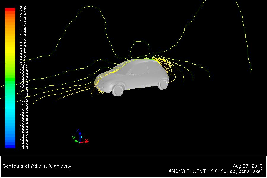
31 Example - Morpher with Shape Optimizer Baseline Design Optimized Design Application: Incompressible turbulent flow over a car Objective Function: Minimise Drag 2010 ANSYS, Inc. All rights reserved. 31 ANSYS, Inc. Proprietary

32 Generic HVAC Duct HVAC duct section of an aircraft with one main outlet and two side outlets Objective: Minimize pressure drop in the duct by optimizing the shape of branch-2 branch outlets Pressure = 0 Pa Inlet Velocity = 10m/s main outlet Pressure = 0 Pa branch 1 branch 2 Baseline Modified 2010 ANSYS, Inc. All rights reserved. 32 ANSYS, Inc. Proprietary
33 Adjoint method 2010 ANSYS, Inc. All rights reserved. 33 ANSYS, Inc. Proprietary
34 What does an adjoint solver do? An adjoint solver provides specific information about a fluid system that is very difficult to gather otherwise. An adjoint solver can be used to compute the derivative of an engineering quantity with respect to all of the inputs for the system. For example Derivative of drag with respect to the shape of a vehicle. Derivative of total pressure drop with respect the shape of the flow path ANSYS, Inc. All rights reserved. 34 ANSYS, Inc. Proprietary
35 Key Ideas - Fundamentals High-level system view of a conventional flow solver Inputs Boundary mesh Interior mesh Material properties Boundary condition 1 Flow angle Inlet velocity FLOW SOLVER Outputs Field data Contour plots Vector plots xy-plots Scalar values Lift Drag Total pressure drop 2010 ANSYS, Inc. All rights reserved. 35 ANSYS, Inc. Proprietary
36 Key Ideas - Fundamentals HOW ARE CHANGES TO KEY OUTPUTS DEPENDENT ON CHANGES TO THE INPUTS? Inputs Boundary mesh Interior mesh Material properties Boundary condition 1 Flow angle Inlet velocity? ADJOINT SOLVER Outputs Field data Contour plots Vector plots xy-plots Scalar values Lift Drag Total pressure drop 2010 ANSYS, Inc. All rights reserved. 36 ANSYS, Inc. Proprietary
 Output R( q; c) 0 Change in output J J q q Change the inputs c by c J c c R R q c q c 0 Residuals of the Navier-Stokes equations Linearized Navier-Stokes Adjoint equations Engineer a")
37 Key Ideas - Fundamentals Flow solution q, and the inputs to the problem c. J( q; c) Output R( q; c) 0 Change in output J J q q Change the inputs c by c J c c R R q c q c 0 Residuals of the Navier-Stokes equations Linearized Navier-Stokes Adjoint equations Engineer a particular linear combination of linearized NS equations introduce multipliers q ~ q~ q R T Change in output J q After substitutions ~ R ~ R q c T T q q q c 0 J T R J q~ Change in c inputs c c 2010 ANSYS, Inc. All rights reserved. 37 ANSYS, Inc. Proprietary
38 Key Ideas Adjoint Equations Construct and solve an adjoint problem to get a helper solution q~ q R T Solve using AMG J q This innocent-looking system of equations is at the heart of the adjoint solver. Involves a familiar process Solution advancement controls Courant number, underrelaxation Residuals & iterations Roughly the same effort as a conventional flow solution 2010 ANSYS, Inc. All rights reserved. 38 ANSYS, Inc. Proprietary

39 Key Ideas Shape Sensitivity Shape sensitivity: Sensitivity of the observed value with respect to (boundary) grid node locations ( Drag) w. x mesh n n Node displacement Shape sensitivity coefficients: Vector field defined on mesh nodes Visualization of shape sensitivity Drag sensitivity for NACA0012 Uses vector field visualization. Identifies regions of high and low sensitivity ANSYS, Inc. All rights reserved. 39 ANSYS, Inc. Proprietary

40 Key Ideas Mesh Moprhing Constrained motion Some walls within the control volume may be constrained not to move. Actual change 3.1 DP = Total improvement of 8% 2010 ANSYS, Inc. All rights reserved. 40 ANSYS, Inc. Proprietary
41 Pressure drop reduction example 2010 ANSYS, Inc. All rights reserved. 41 ANSYS, Inc. Proprietary


42 Key Ideas Mesh Adaptation Solution-based mesh adaptation Regions in the flow domain where the adjoint solution is large have a strong effect of discretization errors in the quantity of interest. Baseline Mesh Adapt in regions where the adjoint solution is large Adapted Mesh Detail Adjoint solution Drag sensitivity Adapted Mesh 2010 ANSYS, Inc. All rights reserved. 42 ANSYS, Inc. Proprietary
43 Current Functionality ANSYS-Fluent flow solver has very broad scope Adjoint is configured to compute solutions based on some assumptions Steady, incompressible, laminar flow. Steady, incompressible, turbulent flow with standard wall functions. First-order discretization in space. Frozen turbulence. The primary flow solution does NOT need to be run with these restrictions Strong evidence that these assumptions do not undermine the utility of the adjoint solution data for engineering purposes. Fully parallelized. Gradient algorithm for shape modification Mesh morphing using control points. Adjoint-based solution adaption 2010 ANSYS, Inc. All rights reserved. 43 ANSYS, Inc. Proprietary


44 Internal flow Simple 3D Total pressure Sensitivity of total pressure drop to shape 2010 ANSYS, Inc. All rights reserved. 44 ANSYS, Inc. Proprietary

45 Internal flow Simple 3D Total pressure drop = Pa Predicted change = 2858 Pa Actual change = 2390 Pa 2010 ANSYS, Inc. All rights reserved. 45 ANSYS, Inc. Proprietary
![Dp tot [Pa] 180 Elbow optimization Thanks to Hauke Reese ANSYS Germany 100 90 80 70 60 50 40](/docs-images/89/100763800/images/46-2.jpg "30 20 10 0 0 10 20 30 Run [-] 2010 ANSYS, Inc. All rights reserved. 46 ANSYS, Inc.")
46 Dp tot [Pa] 180 Elbow optimization Thanks to Hauke Reese ANSYS Germany Run [-] 2010 ANSYS, Inc. All rights reserved. 46 ANSYS, Inc. Proprietary


47 180 Elbow: Optimization Loop Base design End design 2010 ANSYS, Inc. All rights reserved. 47 ANSYS, Inc. Proprietary


48 IC Engine flow Adjoint Residuals Contours of magnitude of shape sensitivity Shape sensitivity vectors 2010 ANSYS, Inc. All rights reserved. 48 ANSYS, Inc. Proprietary


49 External Automotive Aerodynamics Small car Surface map of the drag sensitivity to shape changes Surface map of the drag sensitivity to shape changes Surface map of the drag sensitivity to shape changes 2010 ANSYS, Inc. All rights reserved. 49 ANSYS, Inc. Proprietary

50 Generic F1 Front Wing Example Adjoint computation takes about the same resources as the baseline flow calculation Gives the sensitivity of the downforce to the shape of the wing. Regions of high and low sensitivity 2010 ANSYS, Inc. All rights reserved. 50 ANSYS, Inc. Proprietary


51 Generic F1 Front Wing Example Adjoint solution: Quantifies the effect of specific changes to shape upon downforce Suggests an optimal modification to the shape to enhance downforce Baseline downforce = 905.4N Predicted improvement = 41.6N Actual improvement = 39.1N 2010 ANSYS, Inc. All rights reserved. 51 ANSYS, Inc. Proprietary


52 Generic F1 Front Wing Example 2010 ANSYS, Inc. All rights reserved. 52 ANSYS, Inc. Proprietary
53 Summary 2010 ANSYS, Inc. All rights reserved. 53 ANSYS, Inc. Proprietary
54 Summary Two new approaches to consider The morpher and optimisation provide efficient tool to make and compare geometric adjustments. Consider using the adjoint to guide the morpher. The Adjoint alone is also very useful to identify key sensitivities. These are new technologies which will continue to be enhanced. We encourage you to consider these techniques and will be happy to assist you ANSYS, Inc. All rights reserved. 54 ANSYS, Inc. Proprietary
Mesh Morphing and the Adjoint Solver in ANSYS R14.0. Simon Pereira Laz Foley
 Mesh Morphing and the Adjoint Solver in ANSYS R14.0 Simon Pereira Laz Foley 1 Agenda Fluent Morphing-Optimization Feature RBF Morph with ANSYS DesignXplorer Adjoint Solver What does an adjoint solver do,
Adjoint Solver Workshop
 Adjoint Solver Workshop Why is an Adjoint Solver useful? Design and manufacture for better performance: e.g. airfoil, combustor, rotor blade, ducts, body shape, etc. by optimising a certain characteristic
Optimisationfor CFD. ANSYS R14 Fluids Update Seminar. Milton Park, February 16 th, 2012 Sheffield, February 29 th, 2012 Aberdeen, March 8 th, 2012
 Optimisationfor CFD ANSYS R14 Fluids Update Seminar David Mann, ANSYS UK Ltd. Milton Park, February 16 th, 2012 Sheffield, February 29 th, 2012 Aberdeen, March 8 th, 2012 1 Agenda Optimisation Tools for
Automated Design Exploration and Optimization. Clinton Smith, PhD CAE Support and Training PADT April 26, 2012
 Automated Design Exploration and Optimization Clinton Smith, PhD CAE Support and Training PADT April 26, 2012 1 Agenda The path to robust design A closer look at what DX offers Some examples 2 The Path
RBF Morph An Add-on Module for Mesh Morphing in ANSYS Fluent
 RBF Morph An Add-on Module for Mesh Morphing in ANSYS Fluent Gilles Eggenspieler Senior Product Manager 1 Morphing & Smoothing A mesh morpher is a tool capable of performing mesh modifications in order
Application of Wray-Agarwal Turbulence Model for Accurate Numerical Simulation of Flow Past a Three-Dimensional Wing-body
 Washington University in St. Louis Washington University Open Scholarship Mechanical Engineering and Materials Science Independent Study Mechanical Engineering & Materials Science 4-28-2016 Application
Introduction to ANSYS CFX
 Workshop 03 Fluid flow around the NACA0012 Airfoil 16.0 Release Introduction to ANSYS CFX 2015 ANSYS, Inc. March 13, 2015 1 Release 16.0 Workshop Description: The flow simulated is an external aerodynamics
Multi-objective adjoint optimization of flow in duct and pipe networks
 Multi-objective adjoint optimization of flow in duct and pipe networks Eugene de Villiers Thomas Schumacher 6th OPENFOAM Workshop PennState University, USA 13-16 June, 2011 info@engys.eu Tel: +44 (0)20
Auto Injector Syringe. A Fluent Dynamic Mesh 1DOF Tutorial
 Auto Injector Syringe A Fluent Dynamic Mesh 1DOF Tutorial 1 2015 ANSYS, Inc. June 26, 2015 Prerequisites This tutorial is written with the assumption that You have attended the Introduction to ANSYS Fluent
Shape Optimization for Aerodynamic Efficiency Using Adjoint Methods
 White Paper Shape Optimization for Aerodynamic Efficiency Using Adjoint Methods Adjoint solvers take a Computational Fluid Dynamics (CFD) flow solution and calculate the sensitivity of performance indicators
Adjoint Solver Advances, Tailored to Automotive Applications
 Adjoint Solver Advances, Tailored to Automotive Applications Stamatina Petropoulou s.petropoulou@iconcfd.com 1 Contents 1. Icon s Principal Work in FlowHead 2. Demonstration Cases 3. Icon s Further Development
Introduction to CFX. Workshop 2. Transonic Flow Over a NACA 0012 Airfoil. WS2-1. ANSYS, Inc. Proprietary 2009 ANSYS, Inc. All rights reserved.
 Workshop 2 Transonic Flow Over a NACA 0012 Airfoil. Introduction to CFX WS2-1 Goals The purpose of this tutorial is to introduce the user to modelling flow in high speed external aerodynamic applications.
Flow and Heat Transfer in a Mixing Elbow
 Flow and Heat Transfer in a Mixing Elbow Objectives The main objectives of the project are to learn (i) how to set up and perform flow simulations with heat transfer and mixing, (ii) post-processing and
Introduction to C omputational F luid Dynamics. D. Murrin
 Introduction to C omputational F luid Dynamics D. Murrin Computational fluid dynamics (CFD) is the science of predicting fluid flow, heat transfer, mass transfer, chemical reactions, and related phenomena
Studies of the Continuous and Discrete Adjoint Approaches to Viscous Automatic Aerodynamic Shape Optimization
 Studies of the Continuous and Discrete Adjoint Approaches to Viscous Automatic Aerodynamic Shape Optimization Siva Nadarajah Antony Jameson Stanford University 15th AIAA Computational Fluid Dynamics Conference
Solution Recording and Playback: Vortex Shedding
 STAR-CCM+ User Guide 6663 Solution Recording and Playback: Vortex Shedding This tutorial demonstrates how to use the solution recording and playback module for capturing the results of transient phenomena.
Compressible Flow in a Nozzle
 SPC 407 Supersonic & Hypersonic Fluid Dynamics Ansys Fluent Tutorial 1 Compressible Flow in a Nozzle Ahmed M Nagib Elmekawy, PhD, P.E. Problem Specification Consider air flowing at high-speed through a
Supersonic Flow Over a Wedge
 SPC 407 Supersonic & Hypersonic Fluid Dynamics Ansys Fluent Tutorial 2 Supersonic Flow Over a Wedge Ahmed M Nagib Elmekawy, PhD, P.E. Problem Specification A uniform supersonic stream encounters a wedge
Flow in an Intake Manifold
 Tutorial 2. Flow in an Intake Manifold Introduction The purpose of this tutorial is to model turbulent flow in a simple intake manifold geometry. An intake manifold is a system of passages which carry
Calculate a solution using the pressure-based coupled solver.
 Tutorial 19. Modeling Cavitation Introduction This tutorial examines the pressure-driven cavitating flow of water through a sharpedged orifice. This is a typical configuration in fuel injectors, and brings
Overview and Recent Developments of Dynamic Mesh Capabilities
 Overview and Recent Developments of Dynamic Mesh Capabilities Henrik Rusche and Hrvoje Jasak h.rusche@wikki-gmbh.de and h.jasak@wikki.co.uk Wikki Gmbh, Germany Wikki Ltd, United Kingdom 6th OpenFOAM Workshop,
CFD Topological Optimization of a Car Water-Pump Inlet using TOSCA Fluid and STAR- CCM+
 CFD Topological Optimization of a Car Water-Pump Inlet using TOSCA Fluid and STAR- CCM+ Dr. Anselm Hopf Dr. Andrew Hitchings Les Routledge Ford Motor Company CONTENTS Introduction/Motivation Optimization
Tutorial: Simulating a 3D Check Valve Using Dynamic Mesh 6DOF Model And Diffusion Smoothing
 Tutorial: Simulating a 3D Check Valve Using Dynamic Mesh 6DOF Model And Diffusion Smoothing Introduction The purpose of this tutorial is to demonstrate how to simulate a ball check valve with small displacement
I. Introduction. Optimization Algorithm Components. Abstract for the 5 th OpenFOAM User Conference 2017, Wiesbaden - Germany
 An Aerodynamic Optimization Framework for the Automotive Industry, based on Continuous Adjoint and OpenFOAM E. Papoutsis-Kiachagias 1, V. Asouti 1, K. Giannakoglou 1, K. Gkagkas 2 1) National Technical
Estimating Vertical Drag on Helicopter Fuselage during Hovering
 Estimating Vertical Drag on Helicopter Fuselage during Hovering A. A. Wahab * and M.Hafiz Ismail ** Aeronautical & Automotive Dept., Faculty of Mechanical Engineering, Universiti Teknologi Malaysia, 81310
Using Multiple Rotating Reference Frames
 Tutorial 10. Using Multiple Rotating Reference Frames Introduction Many engineering problems involve rotating flow domains. One example is the centrifugal blower unit that is typically used in automotive
ANSYS Fluid Structure Interaction for Thermal Management and Aeroelasticity
 ANSYS Fluid Structure Interaction for Thermal Management and Aeroelasticity Phil Stopford Duxford Air Museum 11th May 2011 2011 2010 ANSYS, Inc. All rights reserved. 1 ANSYS, Inc. Proprietary Fluid Structure
Aero-Vibro Acoustics For Wind Noise Application. David Roche and Ashok Khondge ANSYS, Inc.
 Aero-Vibro Acoustics For Wind Noise Application David Roche and Ashok Khondge ANSYS, Inc. Outline 1. Wind Noise 2. Problem Description 3. Simulation Methodology 4. Results 5. Summary Thursday, October
Middle East Technical University Mechanical Engineering Department ME 485 CFD with Finite Volume Method Fall 2017 (Dr. Sert)
") Middle East Technical University Mechanical Engineering Department ME 485 CFD with Finite Volume Method Fall 2017 (Dr. Sert) ANSYS Fluent Tutorial Developing Laminar Flow in a 2D Channel 1 How to use This
Middle East Technical University Mechanical Engineering Department ME 485 CFD with Finite Volume Method Fall 2017 (Dr. Sert) ANSYS Fluent Tutorial Developing Laminar Flow in a 2D Channel 1 How to use This
1.2 Numerical Solutions of Flow Problems
 1.2 Numerical Solutions of Flow Problems DIFFERENTIAL EQUATIONS OF MOTION FOR A SIMPLIFIED FLOW PROBLEM Continuity equation for incompressible flow: 0 Momentum (Navier-Stokes) equations for a Newtonian
Modeling Flow Through Porous Media
 Tutorial 7. Modeling Flow Through Porous Media Introduction Many industrial applications involve the modeling of flow through porous media, such as filters, catalyst beds, and packing. This tutorial illustrates
Automated Design Exploration and Optimization + HPC Best Practices
 Automated Design Exploration and Optimization + HPC Best Practices 1 Outline The Path to Robust Design ANSYS DesignXplorer Mesh Morphing and Optimizer RBF Morph Adjoint Solver HPC Best Practices 2 The
Topology Optimization in Fluid Dynamics
 A Methodology for Topology Optimization in Fluid Dynamics 1 Chris Cowan Ozen Engineering, Inc. 1210 E. Arques Ave, Suite 207 Sunnyvale, CA 94085 info@ozeninc.com Ozen Engineering Inc. We are your local
State of the art at DLR in solving aerodynamic shape optimization problems using the discrete viscous adjoint method
 DLR - German Aerospace Center State of the art at DLR in solving aerodynamic shape optimization problems using the discrete viscous adjoint method J. Brezillon, C. Ilic, M. Abu-Zurayk, F. Ma, M. Widhalm
Modeling Unsteady Compressible Flow
 Tutorial 4. Modeling Unsteady Compressible Flow Introduction In this tutorial, FLUENT s density-based implicit solver is used to predict the timedependent flow through a two-dimensional nozzle. As an initial
Using Multiple Rotating Reference Frames
 Tutorial 9. Using Multiple Rotating Reference Frames Introduction Many engineering problems involve rotating flow domains. One example is the centrifugal blower unit that is typically used in automotive
Simulation of Laminar Pipe Flows
 Simulation of Laminar Pipe Flows 57:020 Mechanics of Fluids and Transport Processes CFD PRELAB 1 By Timur Dogan, Michael Conger, Maysam Mousaviraad, Tao Xing and Fred Stern IIHR-Hydroscience & Engineering
Backward facing step Homework. Department of Fluid Mechanics. For Personal Use. Budapest University of Technology and Economics. Budapest, 2010 autumn
 Backward facing step Homework Department of Fluid Mechanics Budapest University of Technology and Economics Budapest, 2010 autumn Updated: October 26, 2010 CONTENTS i Contents 1 Introduction 1 2 The problem
Aerodynamic Study of a Realistic Car W. TOUGERON
 Aerodynamic Study of a Realistic Car W. TOUGERON Tougeron CFD Engineer 2016 Abstract This document presents an aerodynamic CFD study of a realistic car geometry. The aim is to demonstrate the efficiency
CFD MODELING FOR PNEUMATIC CONVEYING
 CFD MODELING FOR PNEUMATIC CONVEYING Arvind Kumar 1, D.R. Kaushal 2, Navneet Kumar 3 1 Associate Professor YMCAUST, Faridabad 2 Associate Professor, IIT, Delhi 3 Research Scholar IIT, Delhi e-mail: arvindeem@yahoo.co.in
Computational Study of Laminar Flowfield around a Square Cylinder using Ansys Fluent
 MEGR 7090-003, Computational Fluid Dynamics :1 7 Spring 2015 Computational Study of Laminar Flowfield around a Square Cylinder using Ansys Fluent Rahul R Upadhyay Master of Science, Dept of Mechanical
Verification of Laminar and Validation of Turbulent Pipe Flows
 1 Verification of Laminar and Validation of Turbulent Pipe Flows 1. Purpose ME:5160 Intermediate Mechanics of Fluids CFD LAB 1 (ANSYS 18.1; Last Updated: Aug. 1, 2017) By Timur Dogan, Michael Conger, Dong-Hwan
Ansys Fluent R Michele Andreoli
 Ansys Fluent R 17.0 Michele Andreoli (m.andreoli@enginsoft.it) Table of contents User Interface Fluent Meshing Solver Numerics New features Innovative Solutions New User Interface: Ribbon-Driven Solver
Verification and Validation of Turbulent Flow around a Clark-Y Airfoil
 Verification and Validation of Turbulent Flow around a Clark-Y Airfoil 1. Purpose 58:160 Intermediate Mechanics of Fluids CFD LAB 2 By Tao Xing and Fred Stern IIHR-Hydroscience & Engineering The University
CFD Analysis of 2-D Unsteady Flow Past a Square Cylinder at an Angle of Incidence
 CFD Analysis of 2-D Unsteady Flow Past a Square Cylinder at an Angle of Incidence Kavya H.P, Banjara Kotresha 2, Kishan Naik 3 Dept. of Studies in Mechanical Engineering, University BDT College of Engineering,
The viscous forces on the cylinder are proportional to the gradient of the velocity field at the
 Fluid Dynamics Models : Flow Past a Cylinder Flow Past a Cylinder Introduction The flow of fluid behind a blunt body such as an automobile is difficult to compute due to the unsteady flows. The wake behind
Analysis of an airfoil
 UNDERGRADUATE RESEARCH FALL 2010 Analysis of an airfoil using Computational Fluid Dynamics Tanveer Chandok 12/17/2010 Independent research thesis at the Georgia Institute of Technology under the supervision
NUMERICAL 3D TRANSONIC FLOW SIMULATION OVER A WING
 Review of the Air Force Academy No.3 (35)/2017 NUMERICAL 3D TRANSONIC FLOW SIMULATION OVER A WING Cvetelina VELKOVA Department of Technical Mechanics, Naval Academy Nikola Vaptsarov,Varna, Bulgaria (cvetelina.velkova1985@gmail.com)
Tutorial 1. Introduction to Using FLUENT: Fluid Flow and Heat Transfer in a Mixing Elbow
 Tutorial 1. Introduction to Using FLUENT: Fluid Flow and Heat Transfer in a Mixing Elbow Introduction This tutorial illustrates the setup and solution of the two-dimensional turbulent fluid flow and heat
Express Introductory Training in ANSYS Fluent Workshop 04 Fluid Flow Around the NACA0012 Airfoil
 Express Introductory Training in ANSYS Fluent Workshop 04 Fluid Flow Around the NACA0012 Airfoil Dimitrios Sofialidis Technical Manager, SimTec Ltd. Mechanical Engineer, PhD PRACE Autumn School 2013 -
A B C D E. Settings Choose height, H, free stream velocity, U, and fluid (dynamic viscosity and density ) so that: Reynolds number
 so that: Reynolds number") Individual task Objective To derive the drag coefficient for a 2D object, defined as where D (N/m) is the aerodynamic drag force (per unit length in the third direction) acting on the object. The object
Individual task Objective To derive the drag coefficient for a 2D object, defined as where D (N/m) is the aerodynamic drag force (per unit length in the third direction) acting on the object. The object
Introduction to Computational Fluid Dynamics Mech 122 D. Fabris, K. Lynch, D. Rich
 Introduction to Computational Fluid Dynamics Mech 122 D. Fabris, K. Lynch, D. Rich 1 Computational Fluid dynamics Computational fluid dynamics (CFD) is the analysis of systems involving fluid flow, heat
Open source software tools for powertrain optimisation
 Open source software tools for powertrain optimisation Paolo Geremia Eugene de Villiers TWO-DAY MEETING ON INTERNAL COMBUSTION ENGINE SIMULATIONS USING OPENFOAM TECHNOLOGY 11-12 July, 2011 info@engys.eu
Steady Flow: Lid-Driven Cavity Flow
 STAR-CCM+ User Guide Steady Flow: Lid-Driven Cavity Flow 2 Steady Flow: Lid-Driven Cavity Flow This tutorial demonstrates the performance of STAR-CCM+ in solving a traditional square lid-driven cavity
AERODYNAMIC DESIGN FOR WING-BODY BLENDED AND INLET
 25 TH INTERNATIONAL CONGRESS OF THE AERONAUTICAL SCIENCES AERODYNAMIC DESIGN FOR WING-BODY BLENDED AND INLET Qingzhen YANG*,Yong ZHENG* & Thomas Streit** *Northwestern Polytechincal University, 772,Xi
Simulation of Turbulent Flow around an Airfoil
 1. Purpose Simulation of Turbulent Flow around an Airfoil ENGR:2510 Mechanics of Fluids and Transfer Processes CFD Lab 2 (ANSYS 17.1; Last Updated: Nov. 7, 2016) By Timur Dogan, Michael Conger, Andrew
Simulation of Flow Development in a Pipe
 Tutorial 4. Simulation of Flow Development in a Pipe Introduction The purpose of this tutorial is to illustrate the setup and solution of a 3D turbulent fluid flow in a pipe. The pipe networks are common
Program: Advanced Certificate Program
 Program: Advanced Certificate Program Course: CFD-Vehicle Aerodynamics Directorate of Training and Lifelong Learning #470-P, Peenya Industrial Area, 4th Phase Peenya, Bengaluru 560 058 www.msruas.ac.in
Swapnil Nimse Project 1 Challenge #2
 Swapnil Nimse Project 1 Challenge #2 Project Overview: Using Ansys-Fluent, analyze dependency of the steady-state temperature at different parts of the system on the flow velocity at the inlet and buoyancy-driven
Driven Cavity Example
 BMAppendixI.qxd 11/14/12 6:55 PM Page I-1 I CFD Driven Cavity Example I.1 Problem One of the classic benchmarks in CFD is the driven cavity problem. Consider steady, incompressible, viscous flow in a square
ANSYS FLUENT. Airfoil Analysis and Tutorial
 ANSYS FLUENT Airfoil Analysis and Tutorial ENGR083: Fluid Mechanics II Terry Yu 5/11/2017 Abstract The NACA 0012 airfoil was one of the earliest airfoils created. Its mathematically simple shape and age
Coupled Analysis of FSI
 Coupled Analysis of FSI Qin Yin Fan Oct. 11, 2008 Important Key Words Fluid Structure Interface = FSI Computational Fluid Dynamics = CFD Pressure Displacement Analysis = PDA Thermal Stress Analysis = TSA
FLUENT Secondary flow in a teacup Author: John M. Cimbala, Penn State University Latest revision: 26 January 2016
 FLUENT Secondary flow in a teacup Author: John M. Cimbala, Penn State University Latest revision: 26 January 2016 Note: These instructions are based on an older version of FLUENT, and some of the instructions
Modeling External Compressible Flow
 Tutorial 3. Modeling External Compressible Flow Introduction The purpose of this tutorial is to compute the turbulent flow past a transonic airfoil at a nonzero angle of attack. You will use the Spalart-Allmaras
CFD Analysis of conceptual Aircraft body
 CFD Analysis of conceptual Aircraft body Manikantissar 1, Dr.Ankur geete 2 1 M. Tech scholar in Mechanical Engineering, SD Bansal college of technology, Indore, M.P, India 2 Associate professor in Mechanical
Verification and Validation of Turbulent Flow around a Clark-Y Airfoil
 1 Verification and Validation of Turbulent Flow around a Clark-Y Airfoil 1. Purpose ME:5160 Intermediate Mechanics of Fluids CFD LAB 2 (ANSYS 19.1; Last Updated: Aug. 7, 2018) By Timur Dogan, Michael Conger,
Module D: Laminar Flow over a Flat Plate
 Module D: Laminar Flow over a Flat Plate Summary... Problem Statement Geometry and Mesh Creation Problem Setup Solution. Results Validation......... Mesh Refinement.. Summary This ANSYS FLUENT tutorial
Tutorial 17. Using the Mixture and Eulerian Multiphase Models
 Tutorial 17. Using the Mixture and Eulerian Multiphase Models Introduction: This tutorial examines the flow of water and air in a tee junction. First you will solve the problem using the less computationally-intensive
ANSYS AIM Tutorial Compressible Flow in a Nozzle
 ANSYS AIM Tutorial Compressible Flow in a Nozzle Author(s): Sebastian Vecchi Created using ANSYS AIM 18.1 Problem Specification Pre-Analysis & Start Up Pre-Analysis Start-Up Geometry Import Geometry Mesh
SPC 307 Aerodynamics. Lecture 1. February 10, 2018
 SPC 307 Aerodynamics Lecture 1 February 10, 2018 Sep. 18, 2016 1 Course Materials drahmednagib.com 2 COURSE OUTLINE Introduction to Aerodynamics Review on the Fundamentals of Fluid Mechanics Euler and
Simulation of Turbulent Flow around an Airfoil
 Simulation of Turbulent Flow around an Airfoil ENGR:2510 Mechanics of Fluids and Transfer Processes CFD Pre-Lab 2 (ANSYS 17.1; Last Updated: Nov. 7, 2016) By Timur Dogan, Michael Conger, Andrew Opyd, Dong-Hwan
This tutorial illustrates how to set up and solve a problem involving solidification. This tutorial will demonstrate how to do the following:
 Tutorial 22. Modeling Solidification Introduction This tutorial illustrates how to set up and solve a problem involving solidification. This tutorial will demonstrate how to do the following: Define a
and to the following students who assisted in the creation of the Fluid Dynamics tutorials:
 Fluid Dynamics CAx Tutorial: Channel Flow Basic Tutorial # 4 Deryl O. Snyder C. Greg Jensen Brigham Young University Provo, UT 84602 Special thanks to: PACE, Fluent, UGS Solutions, Altair Engineering;
Commercial Implementations of Optimization Software and its Application to Fluid Dynamics Problems
 Commercial Implementations of Optimization Software and its Application to Fluid Dynamics Problems Szymon Buhajczuk, M.A.Sc SimuTech Group Toronto Fields Institute Optimization Seminar December 6, 2011
Estimation of Flow Field & Drag for Aerofoil Wing
 Estimation of Flow Field & Drag for Aerofoil Wing Mahantesh. HM 1, Prof. Anand. SN 2 P.G. Student, Dept. of Mechanical Engineering, East Point College of Engineering, Bangalore, Karnataka, India 1 Associate
Simulation of Turbulent Flow over the Ahmed Body
 Simulation of Turbulent Flow over the Ahmed Body 58:160 Intermediate Mechanics of Fluids CFD LAB 4 By Timur K. Dogan, Michael Conger, Maysam Mousaviraad, and Fred Stern IIHR-Hydroscience & Engineering
Coupling of STAR-CCM+ to Other Theoretical or Numerical Solutions. Milovan Perić
 Coupling of STAR-CCM+ to Other Theoretical or Numerical Solutions Milovan Perić Contents The need to couple STAR-CCM+ with other theoretical or numerical solutions Coupling approaches: surface and volume
Team 194: Aerodynamic Study of Airflow around an Airfoil in the EGI Cloud
 Team 194: Aerodynamic Study of Airflow around an Airfoil in the EGI Cloud CFD Support s OpenFOAM and UberCloud Containers enable efficient, effective, and easy access and use of MEET THE TEAM End-User/CFD
Comparisons of Compressible and Incompressible Solvers: Flat Plate Boundary Layer and NACA airfoils
 Comparisons of Compressible and Incompressible Solvers: Flat Plate Boundary Layer and NACA airfoils Moritz Kompenhans 1, Esteban Ferrer 2, Gonzalo Rubio, Eusebio Valero E.T.S.I.A. (School of Aeronautics)
Adjoint Optimization combined with mesh morphing for CFD applications
 Adjoint Optimization combined with mesh morphing for CFD applications Alberto Clarich*, Luca Battaglia*, Enrico Nobile**, Marco Evangelos Biancolini, Ubaldo Cella *ESTECO Spa, Italy. Email: engineering@esteco.com
Speed and Accuracy of CFD: Achieving Both Successfully ANSYS UK S.A.Silvester
 Speed and Accuracy of CFD: Achieving Both Successfully ANSYS UK S.A.Silvester 2010 ANSYS, Inc. All rights reserved. 1 ANSYS, Inc. Proprietary Content ANSYS CFD Introduction ANSYS, the company Simulation
AIRFOIL SHAPE OPTIMIZATION USING EVOLUTIONARY ALGORITHMS
 AIRFOIL SHAPE OPTIMIZATION USING EVOLUTIONARY ALGORITHMS Emre Alpman Graduate Research Assistant Aerospace Engineering Department Pennstate University University Park, PA, 6802 Abstract A new methodology
Fluid structure interaction analysis: vortex shedding induced vibrations
 Fluid structure interaction analysis: vortex shedding induced vibrations N. Di Domenico, M. E. * University of Rome «Tor Vergata», Department of Enterprise Engineering «Mario Lucertini» A. Wade, T. Berg,
TryItNow! Step by Step Walkthrough: Spoiler Support
 TryItNow! Step by Step Walkthrough: Spoiler Support 1 2015 ANSYS, Inc. March 28, 2016 TryItNow! Step by Step Walkthrough: Spoiler Support ANSYS designed this TryItNow! experience to give you quick access
TUTORIAL#3. Marek Jaszczur. Boundary Layer on a Flat Plate W1-1 AGH 2018/2019
 TUTORIAL#3 Boundary Layer on a Flat Plate Marek Jaszczur AGH 2018/2019 W1-1 Problem specification TUTORIAL#3 Boundary Layer - on a flat plate Goal: Solution for boudary layer 1. Creating 2D simple geometry
ANSYS AIM Tutorial Turbulent Flow Over a Backward Facing Step
 ANSYS AIM Tutorial Turbulent Flow Over a Backward Facing Step Author(s): Sebastian Vecchi, ANSYS Created using ANSYS AIM 18.1 Problem Specification Pre-Analysis & Start Up Governing Equation Start-Up Geometry
The Spalart Allmaras turbulence model
 The Spalart Allmaras turbulence model The main equation The Spallart Allmaras turbulence model is a one equation model designed especially for aerospace applications; it solves a modelled transport equation
CFD Topology Optimization of Automotive Components
 CFD Topology Optimization of Automotive Components Dr.-Ing. Markus Stephan, Dr.-Ing. Dipl.-Phys. Pascal Häußler, Dipl.-Math. Michael Böhm FE-DESIGN GmbH, Karlsruhe, Germany Synopsis Automatic CFD optimization
Free-Form Shape Optimization using CAD Models
 Free-Form Shape Optimization using CAD Models D. Baumgärtner 1, M. Breitenberger 1, K.-U. Bletzinger 1 1 Lehrstuhl für Statik, Technische Universität München (TUM), Arcisstraße 21, D-80333 München 1 Motivation
CFD Post-Processing of Rampressor Rotor Compressor
 Gas Turbine Industrial Fellowship Program 2006 CFD Post-Processing of Rampressor Rotor Compressor Curtis Memory, Brigham Young niversity Ramgen Power Systems Mentor: Rob Steele I. Introduction Recent movements
Automatic shape optimisation in hydraulic machinery using OpenFOAM
 Automatic shape optimisation in hydraulic machinery using OpenFOAM 5 th OpenFOAM Workshop, 21-24 June 2010, Gothenburg Jakob Simader Andreas Ruopp Ralf Eisinger Albert Ruprecht Institut of Fluid Mechanics
OzenCloud Case Studies
 OzenCloud Case Studies Case Studies, April 20, 2015 ANSYS in the Cloud Case Studies: Aerodynamics & fluttering study on an aircraft wing using fluid structure interaction 1 Powered by UberCloud http://www.theubercloud.com
CFD Modelling in the Cement Industry
 CFD Modelling in the Cement Industry Victor J. Turnell, P.E., Turnell Corp., USA, describes computational fluid dynamics (CFD) simulation and its benefits in applications in the cement industry. Introduction
Use 6DOF solver to calculate motion of the moving body. Create TIFF files for graphic visualization of the solution.
 Introduction The purpose of this tutorial is to provide guidelines and recommendations for setting up and solving a moving deforming mesh (MDM) case along with the six degree of freedom (6DOF) solver and
Grid. Apr 09, 1998 FLUENT 5.0 (2d, segregated, lam) Grid. Jul 31, 1998 FLUENT 5.0 (2d, segregated, lam)
 Grid. Jul 31, 1998 FLUENT 5.0 (2d, segregated, lam)") Tutorial 2. Around an Airfoil Transonic Turbulent Flow Introduction: The purpose of this tutorial is to compute the turbulent flow past a transonic airfoil at a non-zero angle of attack. You will use the
Tutorial 2. Around an Airfoil Transonic Turbulent Flow Introduction: The purpose of this tutorial is to compute the turbulent flow past a transonic airfoil at a non-zero angle of attack. You will use the
An advanced RBF Morph application: coupled CFD-CSM Aeroelastic Analysis of a Full Aircraft Model and Comparison to Experimental Data
 An advanced RBF Morph application: coupled CFD-CSM Aeroelastic Analysis of a Full Aircraft Model and Comparison to Experimental Data Dr. Marco Evangelos Biancolini Tor Vergata University, Rome, Italy Dr.
TUTORIAL#4. Marek Jaszczur. Turbulent Thermal Boundary Layer on a Flat Plate W1-1 AGH 2018/2019
 TUTORIAL#4 Turbulent Thermal Boundary Layer on a Flat Plate Marek Jaszczur AGH 2018/2019 W1-1 Problem specification TUTORIAL#4 Turbulent Thermal Boundary Layer - on a flat plate Goal: Solution for Non-isothermal
An advanced RBF Morph application: coupled CFD-CSM Aeroelastic Analysis of a Full Aircraft Model and Comparison to Experimental Data
 An advanced RBF Morph application: coupled CFD-CSM Aeroelastic Analysis of a Full Aircraft Model and Comparison to Experimental Data Ubaldo Cella 1 Piaggio Aero Industries, Naples, Italy Marco Evangelos
Integrating multi-body simulation and CFD: toward complex multidisciplinary design optimisation
 Integrating multi-body simulation and CFD: toward complex multidisciplinary design optimisation Federico Urban ESTECO Italy Martin Mühlmeier AUDI Germany Stefano Pieri Department of Energetics University
An Optimization Method Based On B-spline Shape Functions & the Knot Insertion Algorithm
 An Optimization Method Based On B-spline Shape Functions & the Knot Insertion Algorithm P.A. Sherar, C.P. Thompson, B. Xu, B. Zhong Abstract A new method is presented to deal with shape optimization problems.