State of the art at DLR in solving aerodynamic shape optimization problems using the discrete viscous adjoint method
|
|
|
- Lynne Reynolds
- 5 years ago
- Views:
Transcription
1 DLR - German Aerospace Center State of the art at DLR in solving aerodynamic shape optimization problems using the discrete viscous adjoint method J. Brezillon, C. Ilic, M. Abu-Zurayk, F. Ma, M. Widhalm AS - Braunschweig March 2012 Munich, Germany

2 Motivation: Design of a Future Aviation Design of commercial transport aircraft is driven more and more by demands for substantial reduced emissions (ACARE 2020, Flightpath 2050) Design based on high fidelity methods promise helping to find new innovative shapes capable to fulfill stringent constraints Moderate to highly complex geometry under compressible Navier-Stokes equations with models for turbulence and transition = each flow computation suffers from high computational costs (~ hours) Detailed design with large number of design variables (~ 10 to 100 design variables) Need to consider physical constraints (lift, pitching moment,..) Geometrical constraints Multipoint design
3 Motivation: Design of a Future Aviation Design of commercial transport aircraft is driven more and more by demands for substantial reduced emissions (ACARE 2020) Design based on high fidelity methods promise helping to find new innovative shapes capable to fulfill stringent constraints Moderate to highly complex geometry under compressible Navier-Stokes equations with models for turbulence and transition = each flow computation suffers from high computational costs (~ hours) Detailed design with large number of design variables (~ 10 to 100 design variables) Need to consider physical constraints (lift, pitching moment,..) Geometrical constraints Gradient based optimisation strategy Multipoint design
4 Outline 1. Introduction to the adjoint approach 2. Demonstration on 2D cases 3. Demonstration on 3D cases 4. Conclusion
5 Introduction to the adjoint approach Starting Geometry Parameter change Optimum? Parameterisation Mesh procedure Flow simulation Objective function and constraints Gradient based optimisation strategy Gradient based optimiser requires the objective function and the constraints the corresponding gradients! How to compute the gradient: with finite differences di dd I( D + D) D I( D) with I the function of interest D the shape design variable

6 Introduction to the adjoint approach Starting Geometry Parameter change Optimum? Parameterisation Mesh procedure Flow simulation Gradient based optimisation strategy Gradient based optimiser requires the objective function and the constraints the corresponding gradients! How to compute the gradient: with finite differences Objective function and constraints
7 Introduction to the adjoint approach Starting Geometry Parameter change Optimum? Parameterisation Mesh procedure Flow simulation Objective function and constraints Gradient based optimisation strategy Gradient based optimiser requires the objective function and the constraints the corresponding gradients! How to compute the gradient: with finite differences + straight forward + parallel evaluation + n evaluations required + accuracy not guaranteed
8 Introduction to the adjoint approach Starting Geometry Parameter change Optimum? Parameterisation Mesh procedure Flow simulation Gradient based optimisation strategy Gradient based optimiser requires the objective function and the constraints the corresponding gradients! How to compute the gradient: with finite differences with adjoint approach Objective function and constraints
9 I D W If the flow residual is converged, R X R( W, X, D) = 0 Λ and after solving the flow adjoint equation of the function I Introduction to the adjoint approach the function of interest the design vector the flow variables the RANS residual the mesh the flow adjoint vector I T R + Λ = 0 Adjoint equation independent W W to the design variable D the derivatives of I with respect to the shape design vector D becomes di dd = I X X D + Λ T R X X D Metrics terms, independent to W Variation of the function I w.r.t. the shape parameter D by W constant Variation of the RANS residual R w.r.t. the shape parameter D by W constant
10 Introduction to the adjoint approach Computation of the discrete adjoint flow in DLR-Tau code Linearization of the cost function: I W R = 0 W CD, CL, Cm including pressure and viscous comp.; Target Cp Linearization of the residuum for Euler flow for Navier-Stokes with SA and k-ω models Resolution of the flow adjoint equation with PETSC in 2D and 3D (with or without frozen turbulence) FACEMAT in 2D or 3D (but conv. guarantee only for frozen turbulence) AMG solver with Krylov solver for stabilization (currently under test) + Λ T Computation of the continuous adjoint flow in Tau Inviscid formulation in central version available Cost function: CD, CL, Cm
11 Computation of the metric terms di dd = I X X D + Λ T R X X D Strategy 1: with finite differences I I( W, D + D) I( W, D) D D R R( W, D + D) R( W, D ) D D Applications RAE 2822 airfoil Parameterisation with 30 design variables (10 for the thickness and 20 for the camberline) M =0.73, α = 2.0, Re=6.5x10 6 2D viscous calculation with SAE model Discrete flow adjoint and finite differences for the metric terms Need to interpolate the residual on the modified shape lift Viscous drag
12 Markus Widhalm Computation of the metric terms di dd = I X X D + Λ T R X X D Strategy 2: the metric adjoint By introducing the metric adjoint equation I X + Λ T R X + Φ M X = 0 the derivatives of I with respect to D is simply di dd = Φ T T X surf D I D W R X Λ M Φ the function of interest the design vector the flow variables the RANS residual the mesh the flow adjoint vector the mesh deformation the metric adjoint vec. Consequence: if the design vector D represents the mesh points at the surface, the gradient of the cost function is equal to the metric adjoint vector di dd = T Φ

 Mach=0.82, Alpha=1.")

13 Metric adjoint: demonstration on 3D viscous case Wing Body configuration RANS computation (SA model) Mach=0.82, Alpha=1.8, Re=21x10 6 Cp distribution on the surface Drag Sensitivity on the surface
14 Introduction to the adjoint approach in the process chain Starting Geometry Parameter change Optimum? Parameterisation Mesh procedure Flow simulation Objective function and constraints Gradient based optimisation strategy Need the gradient! Flow adjoint Metric adjoint Parametrisation Sensitivities Gradient of the objective function and constraints
15 Introduction to the adjoint approach Starting Geometry Parameter change Optimum? Parameterisation Mesh procedure Flow simulation Objective function and constraints Gradient based optimisation strategy Gradient based optimiser: Requires the objective function and the constraints Requires the gradients! How to compute the gradient: with finite differences with adjoint approach + add process chain + need converged solution + not all function available + accurate gradient + independent of n
16 2D airfoil shape optimisation
17 Single Point Optimisation Optimisation problem RAE 2822 airfoil Objective: drag reduction at constant lift Maximal thickness is kept constant Design condition : M =0.73, CL= Strategy Parameterisation with 20 design variables changing the camberline Mesh deformation 2D Tau calculation on unstructured mesh Resolution of adjoint solutions Results No lift change 21 states and 21x2 gradients evaluations Shock free airfoil
18 Chart 18 > FlowHead Conference > 28 March 2012 Multi-Point optimisation Caslav Ilic Objective Maximize the weighted average of L/D at p points Equidistant points, equally-weighted p=1 CL=0.76; p = 4 points in CL=[0.46, 0.76]; p = 8 points in CL=[0.41, 0.76] Constraints Lift (to determine the polar points) implicitly (TAU target lift) Pitching moment (at each polar point) explicitly handled (SQP) Enclosed volume constant explicitly handled (SQP) Parametrisation In total 30 design parameters controlling the pressure and suction sides Results
19 Optimisation approach for solving inverse design problem Principle Find the geometry that fit a given pressure distribution Strategy Treat the problem as an optimisation problem with the following goal function to minimise: Goal = ( Cp Cp ) ds Body Parametrisation: angle of attack + each surface mesh point Sobolev smoother to ensure smooth shape during the design Mesh deformation Use of TAU-restart for fast CFD evaluation TAU-Adjoint for efficient computation of the gradients Gradient based approach as optimisation algorithm target 2

20 Test Case: Transonic Condition M =0.7; Re= 15x10 6 Result 400 design cycle to match the target pressure Final geometry with blunt nose, very sharp trailing edge, flow condition close to separation near upper trailing edge Verification: pressure distribution computed on the Whitcomd supercritical profile at AoA=0.6
21 Next steps > FlowHead Conference > 28 March 2012 Problems All components for efficient optimizations are integrated but still requires more time than the conventional Takanashi approach Need to define the full pressure distribution (upper and lower side): lengthy iterations to define a feasible target pressure that ensure minimum drag, a given lift and pitching moment coefficients Solution Combine target pressure at specific area (like the upper part) and close the optimisation problem with aerodynamic coefficients Goal = Part Body ( ) 2 Cp Cp ds + Cd + a( Cl Cl ) + b( Cm Cm ) target target target
22 Next steps > FlowHead Conference > 28 March 2012 Fei Ma Preliminary Result Pressure distribution at the upper part of the LV2 airfoil Drag minimisation at target lift Starting geometry is the NACA2412 at M=0.76 ; Re= Optimized geometry match the target pressure and the required lift, with 17.4% less drag than the LV2 profile Promising approach for laminar design based on adjoint approach without the need of the derivation of the transition criteria
23 2D High-Lift problem

 TAU-code in viscous mode with SAE model All TAU discretisations have been")
24 Test case specification (derived from Eurolift II project) Configuration Section of the DLR-F11 at M =0.2 ; Re=20x10 6 ; α=8 º Objective and constraints CL Maximization of OBJ CD CL > CL initial Cm > Cm initial, 3 3D = 2 3D with Cm the pitching nose up moment Penalty to limit the deployment of the flap and slat (constraints from the kinematics of the high-lift system) Strategy Flap shape and position (10 design variables) TAU-code in viscous mode with SAE model All TAU discretisations have been differentiated Krylov-based solver to get the adjoint field
25 Flap design with NLPQL and adjoint approach Results Objective Eurolift II design: optimisation with genetic algorithm + constraints on CLmax
26 Cruise Configuration DLR F6 wing-body configuration


27 Wing optimization of the DLR-F6 Configuration DLR-F6 wing-body configuration Objective and constraints Minimisation of the drag Lift maintained constant Maximum thickness constant Flow condition M 6 =0.75 ; Re=3x10 ; CL=0.5 Approach used Free-Form Deformation to change the camberline and the twist distribution thickness is frozen Parametrisation with 42 or 96 variables Update of the wing-fuselage junction Discrete adjoint approach for gradients evaluation Lift maintained constant by automatically adjusting the angle of incidence during the flow computation


28 Wing optimization of the DLR-F6 Results Optimisation with 42 design variables 20 design cycles 4 gradients comp. with adjoint 8 drag counts reduction Optimisation with 96 design variables 32 design cycles 5 gradients comp. with adjoint 10 drag counts reduction
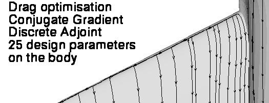
29 Fuselage optimization of the DLR-F6 Strategy Definition of the Free-Form box around the body only 25 nodes are free to move (in spanwise direction) Update of the wing-fuselage junction Gradient based optimizer Discrete adjoint approach for gradients evaluation Lift maintained constant by automatically adjusting the angle of incidence during the flow computation Results 30 design cycles 5 gradients comp. with adjoint 20 drag counts reduction!!! Lift maintained constant
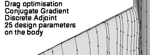

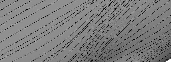
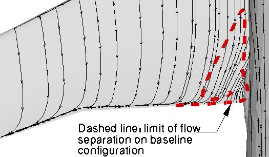
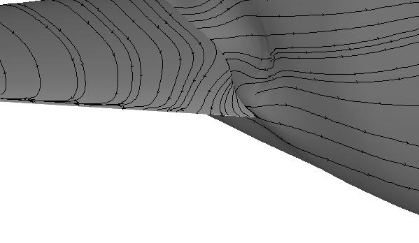
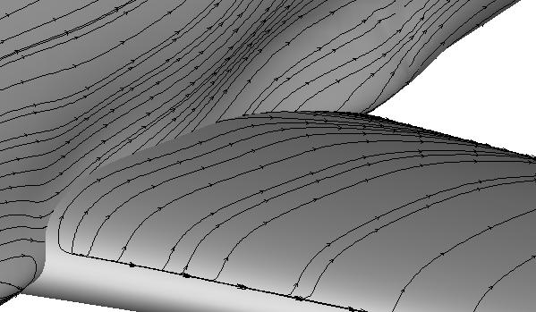
30 Fuselage optimization of the DLR-F6 Streamtraces on the body wing No separation at all, but.


31 Fuselage optimization of the DLR-F6 Streamtraces on the body wing Boeing s FX2B Fairing Tests of WB Configuration in the Onera S2 Facility (2008)
32 Multi-point wing-body optimisation Moh d Abu-Zurayk, Caslav Ilic

 wing thickness implicitly handled (parametrization)")
33 Chart 33 > FlowHead Conference > 28 March 2012 Single-Point L/D in 3D: Problem Setup Objective: maximize the lift to drag ratio Main design point: M = 0.72, Re = , CL = Constraints: lift implicitly handled (TAU target lift) wing thickness implicitly handled (parametrization) Parametrization: 80 free-form deformation control points on the wing. z-displacement, upper/lower points linked 40 design parameters.


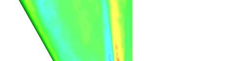


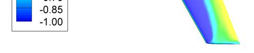


34 Chart 34 > FlowHead Conference > 28 March 2012 Single-Point L/D in 3D: Flow Solution and Sensitivities with adjoint approach c p dc D /dz dc L /dz
35 Chart 35 > FlowHead Conference > 28 March 2012 Single-Point L/D in 3D: results L/D increased from 12.8 to 15.6 (21% up) at design point. Wall clock time: 43 hr on 4 8-core Intel Xeon E5540 nodes.
36 Chart 36 > FlowHead Conference > 28 March 2012 Multi-Point L/D in 3D: results Main Design point: M = 0.82, Re = , CL = Polar points: CL1 = 0.254, CL2 = 0.404, CL3 = Wall clock time: 87 hr on 4 8-core Intel Xeon E5540 nodes.
37 Chart 37 > FlowHead Conference > 28 March 2012 Multi-Point L/D in 3D: results At SP design point (C L3 = 0.554).


38 Chart 38 > FlowHead Conference > 28 March 2012 Single / Multi-Point L/D in 3D Baseline Single point Multipoint
39 Wing flight shape optimisation Moh d Abu-Zurayk


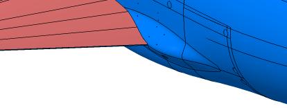
40 Introduction: limitation with classical optimisation (w/o considering structure deformation during the process) Drag minimisation by constant lift (CL=0.554) Drag on the resulting flight shape: +36 DC Optimized Jig Shape No coupling / After coupling


 CSM model (ANSYS) Advantages: huge time reduction and affordability of global sensitivity Global Sensitivity")
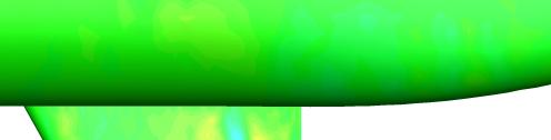
41 The coupled aero-structure adjoint Motivation and formulation Aero-structure deformation has to be considered during the optimisation Need efficient strategy for fast optimisation Gradient approaches are preferred There is a need for an efficient approach to compute the gradients The coupled aero-structure adjoint permits efficient gradient computation Loop over number of parameters Aero Coupling Structure Gradients of design Parameters Finite Differences Coupled Aero-Structure computation Gradients of design Parameters Coupled Adjoint The coupled adjoint formulation was derived and implemented in TAU and Ansys CFD model (TAU) CSM model (ANSYS) Advantages: huge time reduction and affordability of global sensitivity Global Sensitivity of Drag
42 Optimization of the wing flight shape Objective and constraints Drag minimisation by constant lift and thickness Fluid/Structure coupled computations Flow condition M =0.82 ; Re=21x10 6 ; CL=0.554 Shape parametrisation 110 FFD design parameters Body shape kept constant Wing thickness law kept constant Wing shape parametrisation with 40 variables CFD Mesh Centaur hybrid mesh 1.7 Million nodes Mesh deformation using RBF CSM Mesh 27 Ribs, 2 Spars, Lower & Upper Shell 4000 nodes CFD - TAU CSM-ANSYS
43 Optimization of the wing flight shape The coupled adjoint gradients were verified through comparison with gradients obtained by finite differences for Lift and Drag d( C )@ constant Lift dd dc dd dcd dcl ( / dα dα D D = ) dcl dd The structure is frozen (i.e. the structure elements are not changed) but the aero-elastic deformation is considered (flight shape)
44 Optimization of the wing flight shape Results Optimization converged after 35 aero-structural couplings and 11 coupled adjoint computations The optimization reduced the drag by 85 drag counts while keeping the lift and the thickness constant State Alpha CD Initial Optimized
45 Optimization of the wing flight shape Results Optimization converged after 35 aero-structural couplings and 11 coupled adjoint computations The optimization reduced the drag by 85 drag counts while keeping the lift and the thickness constant
46 Multipoint flight shape optimization, early results
47 Conclusion / Outlook Optimisation based on adjoint approach successfully demonstrated on 2D and 3D cases on hybrid grids from Euler to Navier-Stokes (with turbulent model) flows for inverse design and problems based on aero. coefficients Efficient approach to handle detailed aerodynamic shape optimisation problems involving large number of design parameters The coupled aero-structure adjoint is the first step for MDO Next steps toward design capability of a future aviation: More efficiency in solving 3D viscous adjoint flow with turbulence models Efficient computation of the metric terms up to the CAD system Specific cost functions needed by the designer (inverse design on specific area, loads distribution )


48 2D Airfoil > FlowHead Conference > 28 March 2012 Wing in cruise 3D High-Lift Wing Questions? Baseline Optimum Baseline Optimum
Constrained Aero-elastic Multi-Point Optimization Using the Coupled Adjoint Approach
 www.dlr.de Chart 1 Aero-elastic Multi-point Optimization, M.Abu-Zurayk, MUSAF II, 20.09.2013 Constrained Aero-elastic Multi-Point Optimization Using the Coupled Adjoint Approach M. Abu-Zurayk MUSAF II
Aerodynamic Inverse Design Framework using Discrete Adjoint Method
 Aerodynamic Inverse Design Framework using Discrete Adjoint Method Joël Brezillon, Mohammad Abu-Zurayk DLR, Institute of Aerodynamics and Flow Technology Lilienthalplatz 7, D-38108 Braunschweig Joel.Brezillon@dlr.de,
Digital-X. Towards Virtual Aircraft Design and Testing based on High-Fidelity Methods - Recent Developments at DLR -
 Digital-X Towards Virtual Aircraft Design and Testing based on High-Fidelity Methods - Recent Developments at DLR - O. Brodersen, C.-C. Rossow, N. Kroll DLR Institute of Aerodynamics and Flow Technology
Single and multi-point aerodynamic optimizations of a supersonic transport aircraft using strategies involving adjoint equations and genetic algorithm
 Single and multi-point aerodynamic optimizations of a supersonic transport aircraft using strategies involving adjoint equations and genetic algorithm Prepared by : G. Carrier (ONERA, Applied Aerodynamics/Civil
A Cooperative Approach to Multi-Level Multi-Disciplinary Aircraft Optimization
 www.dlr.de Chart 1 ECCOMAS 2016, Greece, Crete, June 5-10, 2016 A Cooperative Approach to Multi-Level Multi-Disciplinary Aircraft Optimization Caslav Ilic, Mohammad Abu-Zurayk Martin Kruse, Stefan Keye,
Status of Gradient-based Airframe MDO at DLR The VicToria Project
 DLR.de Chart 1 Status of Gradient-based Airframe MDO at DLR The VicToria Project M. Abu-Zurayk, C. Ilic, A. Merle, A. Stück, S. Keye, A. Rempke (Institute of Aerodynamics and Flow Technology) T. Klimmek,
Aerodynamic optimization using Adjoint methods and parametric CAD models
 Aerodynamic optimization using Adjoint methods and parametric CAD models ECCOMAS Congress 2016 P. Hewitt S. Marques T. Robinson D. Agarwal @qub.ac.uk School of Mechanical and Aerospace Engineering Queen
THE EFFECTS OF THE PLANFORM SHAPE ON DRAG POLAR CURVES OF WINGS: FLUID-STRUCTURE INTERACTION ANALYSES RESULTS
 March 18-20, 2013 THE EFFECTS OF THE PLANFORM SHAPE ON DRAG POLAR CURVES OF WINGS: FLUID-STRUCTURE INTERACTION ANALYSES RESULTS Authors: M.R. Chiarelli, M. Ciabattari, M. Cagnoni, G. Lombardi Speaker:
Studies of the Continuous and Discrete Adjoint Approaches to Viscous Automatic Aerodynamic Shape Optimization
 Studies of the Continuous and Discrete Adjoint Approaches to Viscous Automatic Aerodynamic Shape Optimization Siva Nadarajah Antony Jameson Stanford University 15th AIAA Computational Fluid Dynamics Conference
Shape optimisation using breakthrough technologies
 Shape optimisation using breakthrough technologies Compiled by Mike Slack Ansys Technical Services 2010 ANSYS, Inc. All rights reserved. 1 ANSYS, Inc. Proprietary Introduction Shape optimisation technologies
Adjoint Solver Workshop
 Adjoint Solver Workshop Why is an Adjoint Solver useful? Design and manufacture for better performance: e.g. airfoil, combustor, rotor blade, ducts, body shape, etc. by optimising a certain characteristic
AERODYNAMIC DESIGN FOR WING-BODY BLENDED AND INLET
 25 TH INTERNATIONAL CONGRESS OF THE AERONAUTICAL SCIENCES AERODYNAMIC DESIGN FOR WING-BODY BLENDED AND INLET Qingzhen YANG*,Yong ZHENG* & Thomas Streit** *Northwestern Polytechincal University, 772,Xi
AERODYNAMIC DESIGN OF FLYING WING WITH EMPHASIS ON HIGH WING LOADING
 AERODYNAMIC DESIGN OF FLYING WING WITH EMPHASIS ON HIGH WING LOADING M. Figat Warsaw University of Technology Keywords: Aerodynamic design, CFD Abstract This paper presents an aerodynamic design process
(c)2002 American Institute of Aeronautics & Astronautics or Published with Permission of Author(s) and/or Author(s)' Sponsoring Organization.
2002 American Institute of Aeronautics & Astronautics or Published with Permission of Author(s) and/or Author(s)' Sponsoring Organization.") VIIA Adaptive Aerodynamic Optimization of Regional Introduction The starting point of any detailed aircraft design is (c)2002 American Institute For example, some variations of the wing planform may become
VIIA Adaptive Aerodynamic Optimization of Regional Introduction The starting point of any detailed aircraft design is (c)2002 American Institute For example, some variations of the wing planform may become
German Aerospace Center, Institute of Aerodynamics and Flow Technology, Numerical Methods
 Automatische Transitionsvorhersage im DLR TAU Code Status der Entwicklung und Validierung Automatic Transition Prediction in the DLR TAU Code - Current Status of Development and Validation Andreas Krumbein
AN INVERSE DESIGN METHOD FOR ENGINE NACELLES AND WINGS
 24th INTERNATIONAL CONGRESS OF THE AERONAUTICAL SCIENCES AN INVERSE DESIGN METHOD FOR ENGINE NACELLES AND WINGS Roland Wilhelm German Aerospace Center DLR, Lilienthalplatz 7, D-388 Braunschweig, Germany
Improvements to a Newton-Krylov Adjoint Algorithm for Aerodynamic Optimization
 Improvements to a Newton-Krylov Adjoint Algorithm for Aerodynamic Optimization David W. Zingg, Timothy M. Leung, Laslo Diosady, Anh H. Truong, and Samy Elias Institute for Aerospace Studies, University
Shock Wave Reduction via Wing-Strut Geometry Design
 Shock Wave Reduction via Wing-Strut Geometry Design Runze LI, Wei NIU, Haixin CHEN School of Aerospace Engineering Beijing 84, China PADRI, Barcelona (Spain) 27..29 SHORT VERSION Shock Wave Reduction via
Geometry Parameterization for Shape Optimization. Arno Ronzheimer
 Geometry Parameterization for Shape Optimization Arno Ronzheimer Dokumentname > 11.07.2006 23.11.2004 Overview Motivation for Geometry Parameterization Classification of Methods Criteria for Choosing a
An advanced RBF Morph application: coupled CFD-CSM Aeroelastic Analysis of a Full Aircraft Model and Comparison to Experimental Data
 An advanced RBF Morph application: coupled CFD-CSM Aeroelastic Analysis of a Full Aircraft Model and Comparison to Experimental Data Ubaldo Cella 1 Piaggio Aero Industries, Naples, Italy Marco Evangelos
An efficient method for predicting zero-lift or boundary-layer drag including aeroelastic effects for the design environment
 The Aeronautical Journal November 2015 Volume 119 No 1221 1451 An efficient method for predicting zero-lift or boundary-layer drag including aeroelastic effects for the design environment J. A. Camberos
Keisuke Sawada. Department of Aerospace Engineering Tohoku University
 March 29th, 213 : Next Generation Aircraft Workshop at Washington University Numerical Study of Wing Deformation Effect in Wind-Tunnel Testing Keisuke Sawada Department of Aerospace Engineering Tohoku
Aerofoil Optimisation Using CST Parameterisation in SU2
 Aerofoil Optimisation Using CST Parameterisation in SU2 Marques, S., & Hewitt, P. (2014). Aerofoil Optimisation Using CST Parameterisation in SU2. Paper presented at Royal Aeronautical Society Applied
Modeling External Compressible Flow
 Tutorial 3. Modeling External Compressible Flow Introduction The purpose of this tutorial is to compute the turbulent flow past a transonic airfoil at a nonzero angle of attack. You will use the Spalart-Allmaras
Recent developments for the multigrid scheme of the DLR TAU-Code
 www.dlr.de Chart 1 > 21st NIA CFD Seminar > Axel Schwöppe Recent development s for the multigrid scheme of the DLR TAU-Code > Apr 11, 2013 Recent developments for the multigrid scheme of the DLR TAU-Code
NUMERICAL 3D TRANSONIC FLOW SIMULATION OVER A WING
 Review of the Air Force Academy No.3 (35)/2017 NUMERICAL 3D TRANSONIC FLOW SIMULATION OVER A WING Cvetelina VELKOVA Department of Technical Mechanics, Naval Academy Nikola Vaptsarov,Varna, Bulgaria (cvetelina.velkova1985@gmail.com)
Debojyoti Ghosh. Adviser: Dr. James Baeder Alfred Gessow Rotorcraft Center Department of Aerospace Engineering
 Debojyoti Ghosh Adviser: Dr. James Baeder Alfred Gessow Rotorcraft Center Department of Aerospace Engineering To study the Dynamic Stalling of rotor blade cross-sections Unsteady Aerodynamics: Time varying
Application of Jetstream to a Suite of Aerodynamic Shape Optimization Problems. Karla Telidetzki
 Application of Jetstream to a Suite of Aerodynamic Shape Optimization Problems by Karla Telidetzki A thesis submitted in conformity with the requirements for the degree of Master of Applied Science Graduate
An Optimization Method Based On B-spline Shape Functions & the Knot Insertion Algorithm
 An Optimization Method Based On B-spline Shape Functions & the Knot Insertion Algorithm P.A. Sherar, C.P. Thompson, B. Xu, B. Zhong Abstract A new method is presented to deal with shape optimization problems.
AIRFOIL SHAPE OPTIMIZATION USING EVOLUTIONARY ALGORITHMS
 AIRFOIL SHAPE OPTIMIZATION USING EVOLUTIONARY ALGORITHMS Emre Alpman Graduate Research Assistant Aerospace Engineering Department Pennstate University University Park, PA, 6802 Abstract A new methodology
Application of Wray-Agarwal Turbulence Model for Accurate Numerical Simulation of Flow Past a Three-Dimensional Wing-body
 Washington University in St. Louis Washington University Open Scholarship Mechanical Engineering and Materials Science Independent Study Mechanical Engineering & Materials Science 4-28-2016 Application
TAU mesh deformation. Thomas Gerhold
 TAU mesh deformation Thomas Gerhold The parallel mesh deformation of the DLR TAU-Code Introduction Mesh deformation method & Parallelization Results & Applications Conclusion & Outlook Introduction CFD
Usage of CFX for Aeronautical Simulations
 Usage of CFX for Aeronautical Simulations Florian Menter Development Manager Scientific Coordination ANSYS Germany GmbH Overview Elements of CFD Technology for aeronautical simulations: Grid generation
Introduction to ANSYS CFX
 Workshop 03 Fluid flow around the NACA0012 Airfoil 16.0 Release Introduction to ANSYS CFX 2015 ANSYS, Inc. March 13, 2015 1 Release 16.0 Workshop Description: The flow simulated is an external aerodynamics
Hybrid Simulation of Wake Vortices during Landing HPCN-Workshop 2014
 Hybrid Simulation of Wake Vortices during Landing HPCN-Workshop 2014 A. Stephan 1, F. Holzäpfel 1, T. Heel 1 1 Institut für Physik der Atmosphäre, DLR, Oberpfaffenhofen, Germany Aircraft wake vortices
INVERSE METHODS FOR AERODYNAMIC DESIGN USING THE NAVIER-STOKES EQUATIONS
 INVERSE METHODS FOR AERODYNAMIC DESIGN USING THE NAVIER-STOKES EQUATIONS I.A. Gubanova, M.A. Gubanova Central Aerohydrodynamic Institute (TsAGI) Keywords: inverse method, Navier Stokes equations, ANSYS
High-Lift Aerodynamics: STAR-CCM+ Applied to AIAA HiLiftWS1 D. Snyder
 High-Lift Aerodynamics: STAR-CCM+ Applied to AIAA HiLiftWS1 D. Snyder Aerospace Application Areas Aerodynamics Subsonic through Hypersonic Aeroacoustics Store release & weapons bay analysis High lift devices
Aerodynamic Shape Optimization Using the Discrete Adjoint of the Navier-Stokes Equations: Applications towards Complex 3D Configurations
 Paper No. 36-1 Aerodynamic Shape Optimization Using the Discrete Adjoint of the Navier-Stoes Equations: Applications towards Complex 3D Configurations Joël Brezillon, Richard P. Dwight German Aerospace
39th AIAA Aerospace Sciences Meeting and Exhibit January 8 11, 2001/Reno, NV
 AIAA 1 717 Static Aero-elastic Computation with a Coupled CFD and CSD Method J. Cai, F. Liu Department of Mechanical and Aerospace Engineering University of California, Irvine, CA 92697-3975 H.M. Tsai,
Introduction to CFX. Workshop 2. Transonic Flow Over a NACA 0012 Airfoil. WS2-1. ANSYS, Inc. Proprietary 2009 ANSYS, Inc. All rights reserved.
 Workshop 2 Transonic Flow Over a NACA 0012 Airfoil. Introduction to CFX WS2-1 Goals The purpose of this tutorial is to introduce the user to modelling flow in high speed external aerodynamic applications.
Fluid-Structure Coupling for Aerodynamic Analysis and Design A DLR Perspective
 46th AIAA Aerospace Sciences Meeting and Exhibit 7-10 January 2008, Reno, Nevada AIAA 2008-561 Fluid-Structure Coupling for Aerodynamic Analysis and Design A DLR Perspective R. Heinrich 1 and N. Kroll.
How to Enter and Analyze a Wing
 How to Enter and Analyze a Wing Entering the Wing The Stallion 3-D built-in geometry creation tool can be used to model wings and bodies of revolution. In this example, a simple rectangular wing is modeled
UNSTEADY TAU AND ROM FOR FLUTTER COMPUTATIONS OF TRANSPORT AIRCRAFT. Reik Thormann, Ralph Voß. Folie 1
 UNSTEADY TAU AND ROM FOR FLUTTER COMPUTATIONS OF TRANSPORT AIRCRAFT Reik Thormann, Ralph Voß Folie 1 Standardfoliensatz >01.03.2007 Outline Motivation Synthetic Mode Correction (SMC) Linearized CFD Method
Multi-Element High-Lift Configuration Design Optimization Using Viscous Continuous Adjoint Method
 JOURNAL OF AIRCRAFT Vol. 41, No. 5, September October 2004 Multi-Element High-Lift Configuration Design Optimization Using Viscous Continuous Adjoint Method Sangho Kim, Juan J. Alonso, and Antony Jameson
Development of a Consistent Discrete Adjoint Solver for the SU 2 Framework
 Development of a Consistent Discrete Adjoint Solver for the SU 2 Framework Tim Albring, Max Sagebaum, Nicolas Gauger Chair for Scientific Computing TU Kaiserslautern 16th Euro-AD Workshop, Jena December
Optimization with Gradient and Hessian Information Calculated Using Hyper-Dual Numbers
 Optimization with Gradient and Hessian Information Calculated Using Hyper-Dual Numbers Jeffrey A. Fike and Juan J. Alonso Department of Aeronautics and Astronautics, Stanford University, Stanford, CA 94305,
Subsonic Airfoils. W.H. Mason Configuration Aerodynamics Class
 Subsonic Airfoils W.H. Mason Configuration Aerodynamics Class Most people don t realize that mankind can be divided into two great classes: those who take airfoil selection seriously, and those who don
Challenges in Boundary- Layer Stability Analysis Based On Unstructured Grid Solutions
 Challenges in Boundary- Layer Stability Analysis Based On Unstructured Grid Solutions Wei Liao National Institute of Aerospace, Hampton, Virginia Collaborators: Mujeeb R. Malik, Elizabeth M. Lee- Rausch,
OPTIMISATION OF THE HELICOPTER FUSELAGE WITH SIMULATION OF MAIN AND TAIL ROTOR INFLUENCE
 28 TH INTERNATIONAL CONGRESS OF THE AERONAUTICAL SCIENCES OPTIMISATION OF THE HELICOPTER FUSELAGE WITH Wienczyslaw Stalewski*, Jerzy Zoltak* * Institute of Aviation, Poland stal@ilot.edu.pl;geor@ilotl.edu.pl
High-fidelity Multidisciplinary Design Optimization for Next-generation Aircraft
 High-fidelity Multidisciplinary Design Optimization for Next-generation Aircraft Joaquim R. R. A. Martins with contributions from John T. Hwang, Gaetan K. W. Kenway, Graeme J. Kennedy, Zhoujie Lyu CFD
TAU User Meeting, Göttingen,
 TAU User Meeting, Göttingen, 22.9.2005 Fluid-Structure-Coupling Using the TAU Code: Developments and Applications at the DLR Institute of Aeroelasticity Wolf Krüger DLR Institute of Aeroelasticity Fluid-Structure-Coupling
CFD Methods for Aerodynamic Design
 CFD Methods for Aerodynamic Design Afandi Darlington Optimal Aerodynamics Ltd Why CFD? Datasheet methods are still very relevant today (ESDU, USAF DATCOM) Validated estimates of lift, drag, moments, stability
Aerodynamic Analysis of Forward Swept Wing Using Prandtl-D Wing Concept
 Aerodynamic Analysis of Forward Swept Wing Using Prandtl-D Wing Concept Srinath R 1, Sahana D S 2 1 Assistant Professor, Mangalore Institute of Technology and Engineering, Moodabidri-574225, India 2 Assistant
Missile External Aerodynamics Using Star-CCM+ Star European Conference 03/22-23/2011
 Missile External Aerodynamics Using Star-CCM+ Star European Conference 03/22-23/2011 StarCCM_StarEurope_2011 4/6/11 1 Overview 2 Role of CFD in Aerodynamic Analyses Classical aerodynamics / Semi-Empirical
Multi-point Aero-Structural Optimization of Wings Including Planform Variations
 45 th Aerospace Sciences Meeting and Exhibit, January 8, 007, Reno, Nevada Multi-point Aero-Structural Optimization of Wings Including Planform Variations Antony Jameson, Kasidit Leoviriyakit and Sriram
Efficient Multi-point Aerodynamic Design Optimization Via Co-Kriging
 Efficient Multi-point Aerodynamic Design Optimization Via Co-Kriging David J. J. Toal and Andy J. Keane 2 University of Southampton, Southampton, SO7 BJ, United Kingdom Multi-point objective functions
Automatic Differentiation Adjoint of the Reynolds-Averaged Navier Stokes Equations with a Turbulence Model
 Automatic Differentiation Adjoint of the Reynolds-Averaged Navier Stokes Equations with a Turbulence Model Zhoujie Lyu and Gaetan K.W. Kenway Department of Aerospace Engineering, University of Michigan,
UNSTRUCTURED MESH CAPABILITES FOR SUPERSONIC WING DESIGN AT LOW SPEED CONDITIONS
 CFD & OPTIMIZATION 2011-048 An ECCOMAS Thematic Conference 23-25 May 2011, Antalya TURKEY UNSTRUCTURED MESH CAPABILITES FOR SUPERSONIC WING DESIGN AT LOW SPEED CONDITIONS Michele Gaffuri, Joël Brezillon
Computation of Sensitivity Derivatives of Navier-Stokes Equations using Complex Variables
 Computation of Sensitivity Derivatives of Navier-Stokes Equations using Complex Variables By Veer N. Vatsa NASA Langley Research Center, Hampton, VA 23681 Mail Stop 128, email: v.n.vatsa@larc.nasa.gov
GAs for aerodynamic shape design II: multiobjective optimization and multi-criteria design
 GAs for aerodynamic shape design II: multiobjective optimization and multi-criteria design D. Quagliarella, A. Vicini C.I.R.A., Centro Italiano Ricerche Aerospaziali Via Maiorise 8143 Capua (Italy) Abstract
Aerospace Applications of Optimization under Uncertainty
 Aerospace Applications of Optimization under Uncertainty Sharon Padula, Clyde Gumbert, and Wu Li NASA Langley Research Center Abstract The Multidisciplinary Optimization (MDO) Branch at NASA Langley Research
Subsonic Airfoils. W.H. Mason Configuration Aerodynamics Class
 Subsonic Airfoils W.H. Mason Configuration Aerodynamics Class Typical Subsonic Methods: Panel Methods For subsonic inviscid flow, the flowfield can be found by solving an integral equation for the potential
Mesh Morphing and the Adjoint Solver in ANSYS R14.0. Simon Pereira Laz Foley
 Mesh Morphing and the Adjoint Solver in ANSYS R14.0 Simon Pereira Laz Foley 1 Agenda Fluent Morphing-Optimization Feature RBF Morph with ANSYS DesignXplorer Adjoint Solver What does an adjoint solver do,
Shape optimization for aerodynamic design: Dassault Aviation challenges and new trends
 Direction Générale Technique Shape optimization for aerodynamic design: Dassault Aviation challenges and new trends Forum TERATEC 014 Atelier «Conception numérique optimale des systèmes complexes : état
Multidisciplinary design optimization (MDO) of a typical low aspect ratio wing using Isight
 of a typical low aspect ratio wing using Isight") Multidisciplinary design optimization (MDO) of a typical low aspect ratio wing using Isight Mahadesh Kumar A 1 and Ravishankar Mariayyah 2 1 Aeronautical Development Agency and 2 Dassault Systemes India
Multidisciplinary design optimization (MDO) of a typical low aspect ratio wing using Isight Mahadesh Kumar A 1 and Ravishankar Mariayyah 2 1 Aeronautical Development Agency and 2 Dassault Systemes India
Numerical Investigation of Transonic Shock Oscillations on Stationary Aerofoils
 Numerical Investigation of Transonic Shock Oscillations on Stationary Aerofoils A. Soda, T. Knopp, K. Weinman German Aerospace Center DLR, Göttingen/Germany Symposium on Hybrid RANS-LES Methods Stockholm/Sweden,
An advanced RBF Morph application: coupled CFD-CSM Aeroelastic Analysis of a Full Aircraft Model and Comparison to Experimental Data
 An advanced RBF Morph application: coupled CFD-CSM Aeroelastic Analysis of a Full Aircraft Model and Comparison to Experimental Data Dr. Marco Evangelos Biancolini Tor Vergata University, Rome, Italy Dr.
Comparison of B-spline Surface and Free-form. Deformation Geometry Control for Aerodynamic. Optimization
 Comparison of B-spline Surface and Free-form Deformation Geometry Control for Aerodynamic Optimization Christopher Lee,DavidKoo and David W. Zingg Institute for Aerospace Studies, University of Toronto
The Spalart Allmaras turbulence model
 The Spalart Allmaras turbulence model The main equation The Spallart Allmaras turbulence model is a one equation model designed especially for aerospace applications; it solves a modelled transport equation
HPC Usage for Aerodynamic Flow Computation with Different Levels of Detail
 DLR.de Folie 1 HPCN-Workshop 14./15. Mai 2018 HPC Usage for Aerodynamic Flow Computation with Different Levels of Detail Cornelia Grabe, Marco Burnazzi, Axel Probst, Silvia Probst DLR, Institute of Aerodynamics
A DRAG PREDICTION VALIDATION STUDY FOR AIRCRAFT AERODYNAMIC ANALYSIS
 A DRAG PREDICTION VALIDATION STUDY FOR AIRCRAFT AERODYNAMIC ANALYSIS Akio OCHI, Eiji SHIMA Kawasaki Heavy Industries, ltd Keywords: CFD, Drag prediction, Validation Abstract A CFD drag prediction validation
Adjoint-Based Sensitivity Analysis for Computational Fluid Dynamics
 Adjoint-Based Sensitivity Analysis for Computational Fluid Dynamics Dimitri J. Mavriplis Max Castagne Professor Department of Mechanical Engineering University of Wyoming Laramie, WY USA Motivation Computational
MULTI-OBJECTIVE OPTIMISATION IN MODEFRONTIER FOR AERONAUTIC APPLICATIONS
 EVOLUTIONARY METHODS FOR DESIGN, OPTIMIZATION AND CONTROL P. Neittaanmäki, J. Périaux and T. Tuovinen (Eds.) CIMNE, Barcelona, Spain 2007 MULTI-OBJECTIVE OPTIMISATION IN MODEFRONTIER FOR AERONAUTIC APPLICATIONS
Validation of an Unstructured Overset Mesh Method for CFD Analysis of Store Separation D. Snyder presented by R. Fitzsimmons
 Validation of an Unstructured Overset Mesh Method for CFD Analysis of Store Separation D. Snyder presented by R. Fitzsimmons Stores Separation Introduction Flight Test Expensive, high-risk, sometimes catastrophic
THE use of computer algorithms for aerodynamic shape
 AIAA JOURNAL Vol. 51, No. 6, June 2013 Multimodality and Global Optimization in Aerodynamic Design Oleg Chernukhin and David W. ingg University of Toronto, Toronto, Ontario M3H 5T6, Canada DOI: 10.2514/1.J051835
Interdisciplinary Wing Design Structural Aspects
 03WAC-29 Interdisciplinary Wing Design Structural Aspects Christian Anhalt, Hans Peter Monner, Elmar Breitbach German Aerospace Center (DLR), Institute of Structural Mechanics Copyright 2003 SAE International
Impact of Computational Aerodynamics on Aircraft Design
 Impact of Computational Aerodynamics on Aircraft Design Outline Aircraft Design Process Aerodynamic Design Process Wind Tunnels &Computational Aero. Impact on Aircraft Design Process Revealing details
AERODYNAMIC SHAPES DESIGN ON THE BASE OF DIRECT NEWTON TYPE OPTIMIZATION METHOD
 AERODYNAMIC SHAPES DESIGN ON THE BASE OF DIRECT NEWTON TYPE OPTIMIZATION METHOD A.V. Grachev*, A.N. Kraiko**, S.A. Takovitskii* *Central Aerohydrodynamic Institute (TsAGI), **Central Institute of Aviation
Efficient Aero-Acoustic Simulation of the HART II Rotor with the Compact Pade Scheme Gunther Wilke DLR AS-HEL Sept 6th nd ERF Lille, France
 www.dlr.de Chart 1 Efficient Aero-Acoustic Simulation of the HART II Rotor with the Compact Pade Scheme Gunther Wilke DLR AS-HEL Sept 6th 2016 42nd ERF Lille, France www.dlr.de Chart 2 Overview - Motivation
RESPONSE SURFACE BASED OPTIMIZATION WITH A CARTESIAN CFD METHOD
 AIAA-23-465 RESPONSE SURFACE BASED OPTIMIZATION WITH A CARTESIAN CFD METHOD David L. Rodriguez * Stanford University Stanford, CA Abstract Cartesian-based CFD methods are quite powerful in preliminary
Study of Swept Angle Effects on Grid Fins Aerodynamics Performance
 Journal of Physics: Conference Series PAPER OPEN ACCESS Study of Swept Angle Effects on Grid Fins Aerodynamics Performance To cite this article: G A Faza et al 2018 J. Phys.: Conf. Ser. 1005 012013 View
AERODYNAMIC OPTIMIZATION OF NEAR-SONIC PLANE BASED ON NEXST-1 SST MODEL
 24 TH INTERNATIONAL CONGRESS OF THE AERONAUTICAL SCIENCES AERODYNAMIC OPTIMIZATION OF NEAR-SONIC PLANE BASED ON SST MODEL Department of Aeronautics & Space Engineering, Tohoku University Aramaki-Aza-Aoba01,
ADJOINT OPTIMIZATION OF 2D-AIRFOILS IN INCOMPRESSIBLE FLOWS
 11th World Congress on Computational Mechanics (WCCM XI) 5th European Conference on Computational Mechanics (ECCM V) 6th European Conference on Computational Fluid Dynamics (ECFD VI) E. Oñate, J. Oliver
AIR LOAD CALCULATION FOR ISTANBUL TECHNICAL UNIVERSITY (ITU), LIGHT COMMERCIAL HELICOPTER (LCH) DESIGN ABSTRACT
, LIGHT COMMERCIAL HELICOPTER (LCH) DESIGN ABSTRACT") AIR LOAD CALCULATION FOR ISTANBUL TECHNICAL UNIVERSITY (ITU), LIGHT COMMERCIAL HELICOPTER (LCH) DESIGN Adeel Khalid *, Daniel P. Schrage + School of Aerospace Engineering, Georgia Institute of Technology
AIR LOAD CALCULATION FOR ISTANBUL TECHNICAL UNIVERSITY (ITU), LIGHT COMMERCIAL HELICOPTER (LCH) DESIGN Adeel Khalid *, Daniel P. Schrage + School of Aerospace Engineering, Georgia Institute of Technology
Finite Element Flow Simulations of the EUROLIFT DLR-F11 High Lift Configuration
 Finite Element Flow Simulations of the EUROLIFT DLR-F11 High Lift Configuration Kedar C. Chitale MANE Dept., Rensselaer Polytechnic Institute, NY 12180 Michel Rasquin Leadership Computing Facility, Argonne
OVER-THE-WING-NACELLE-MOUNT CONFIGURATION FOR NOISE REDUCTION
 27 TH INTERNATIONAL CONGRESS OF THE AERONAUTICAL SCIENCES OVER-THE-WING-NACELLE-MOUNT CONFIGURATION FOR NOISE REDUCTION Daisuke Sasaki*, Ryota Yoneta*, Kazuhiro Nakahashi* *Department of Aerospace Engineering,
Optimization of Laminar Wings for Pro-Green Aircrafts
 Optimization of Laminar Wings for Pro-Green Aircrafts André Rafael Ferreira Matos Abstract This work falls within the scope of aerodynamic design of pro-green aircraft, where the use of wings with higher
Aerodynamic Design of a Tailless Aeroplan J. Friedl
 Acta Polytechnica Vol. 4 No. 4 5/2 Aerodynamic Design of a Tailless Aeroplan J. Friedl The paper presents an aerodynamic analysis of a one-seat ultralight (UL) tailless aeroplane named L2k, with a very
OPTIMIZATIONS OF AIRFOIL AND WING USING GENETIC ALGORITHM
 ICAS22 CONGRESS OPTIMIZATIONS OF AIRFOIL AND WING USING GENETIC ALGORITHM F. Zhang, S. Chen and M. Khalid Institute for Aerospace Research (IAR) National Research Council (NRC) Ottawa, K1A R6, Ontario,
This is a repository copy of Nonconsistent mesh movement and sensitivity calculation on adjoint aerodynamic optimization.
 This is a repository copy of Nonconsistent mesh movement and sensitivity calculation on adjoint aerodynamic optimization. White Rose Research Online URL for this paper: http://eprints.whiterose.ac.uk/130140/
4. RHEOELECTRIC ANALOGY
 4. RHEOELECTRIC ANALOGY 4.1 Rheoelectric tank for transonic flow analogy The structure of the particular solutions used for the illustrated examples gives information also about the details of the mapping
Computational Fluid Dynamics for Engineers
 Tuncer Cebeci Jian P. Shao Fassi Kafyeke Eric Laurendeau Computational Fluid Dynamics for Engineers From Panel to Navier-Stokes Methods with Computer Programs With 152 Figures, 19 Tables, 84 Problems and
I. Introduction. Optimization Algorithm Components. Abstract for the 5 th OpenFOAM User Conference 2017, Wiesbaden - Germany
 An Aerodynamic Optimization Framework for the Automotive Industry, based on Continuous Adjoint and OpenFOAM E. Papoutsis-Kiachagias 1, V. Asouti 1, K. Giannakoglou 1, K. Gkagkas 2 1) National Technical
2 Aircraft Design Sequence
 2-1 2 Aircraft Design Sequence The sequence of activities during the project phase (see Fig. 1.3) can be divided in two steps: 1.) preliminary sizing 2.) conceptual design. Beyond this there is not much
CFD BASED OPTIMIZATION OF HIGH-LIFT DEVICES USING A MESH MORPHING TECHNIQUE
 CFD BASED OPTIMIZATION OF HIGH-LIFT DEVICES USING A MESH MORPHING TECHNIQUE Ricardo G. Silva, Alexandre P. Antunes, Ricardo B. Flatschart, João L. F. Azevedo Universidade de São Paulo, São Paulo, SP, Brazil
Grid Discretization Study for the Efficient Aerodynamic Analysis of the Very Light Aircraft (VLA) Configuration
 Configuration") Paper Int l J. of Aeronautical & Space Sci. 14(2), 122-132 (2013) DOI:10.5139/IJASS.2013.14.2.122 Grid Discretization Study for the Efficient Aerodynamic Analysis of the Very Light Aircraft (VLA) Configuration
Paper Int l J. of Aeronautical & Space Sci. 14(2), 122-132 (2013) DOI:10.5139/IJASS.2013.14.2.122 Grid Discretization Study for the Efficient Aerodynamic Analysis of the Very Light Aircraft (VLA) Configuration
TOPOLOGY OPTIMIZATION OF WING RIBS IN CESSNA CITATION
 TOPOLOGY OPTIMIZATION OF WING RIBS IN CESSNA CITATION [1],Sathiyavani S [2], Arun K K [3] 1,2 student, 3 Assistant professor Kumaraguru College of technology, Coimbatore Abstract Structural design optimization
Algorithmic Developments in TAU
 Algorithmic Developments in TAU Ralf Heinrich, Richard Dwight, Markus Widhalm, and Axel Raichle DLR Institute of Aerodynamics and Flow Technology, Lilienthalplatz 7, 38108, Germany ralf.heinrich@dlr.de,
CONFIGURATION TEST CASES FOR AIRCRAFT WING ROOT DESIGN AND OPTIMIZATION
 Proc. Int. Symp. on Inverse Problems in Engineering Mechanics (ISIP 98), 24-27 March 1998, Nagano, Japan Elsevier Science, (1998) CONFIGURATION TEST CASES FOR AIRCRAFT WING ROOT DESIGN AND OPTIMIZATION
Morphing high lift structures: Smart leading edge device and smart single slotted flap Hans Peter Monner, Johannes Riemenschneider Madrid, 30 th
 Morphing high lift structures: Smart leading edge device and smart single slotted flap Hans Peter Monner, Johannes Riemenschneider Madrid, 30 th March 2011 Outline Background Project overview Selected