Automated Design Exploration and Optimization. Clinton Smith, PhD CAE Support and Training PADT April 26, 2012
|
|
|
- Harvey Barker
- 6 years ago
- Views:
Transcription

1 Automated Design Exploration and Optimization Clinton Smith, PhD CAE Support and Training PADT April 26,
2 Agenda The path to robust design A closer look at what DX offers Some examples 2


3 The Path to Robust Design Robust Design is an ANSYS Advantage Single Physics Solution Accuracy, robustness, speed Multiphysics Solution Integration Platform What if Study Parametric Platform Design Exploration DOE, Response Surfaces, Correlation, Sensitivity, Unified reporting, etc. Optimization Algorithms Published API Robust Design Six Sigma Analysis Probabilistic Algorithms Adjoint solver methods 3


4 Single Physics/Multi Physics Single physics is the entry point to Simulation Multi-Physics enables real virtual prototyping Fluid Pressure Distribution 2 way coupled with a transient structural solution Stress? Electromagnetic Force Density with Thermal-Stress and Electromagnetic Force load Deformation of the Stator? 4


5 What If? Interactively adjust the parameter values and Update Needed for "What If?" Parametric CAD Connections Pervasive Parameters Persistent Updates Managed State, Update Mechanisms Remote Solve Manager (RSM) Parametric Persistence is an ANSYS Advantage! 5
6 Design Exploration Design Exploration is an ANSYS Advantage 6


7 Optimization Optimal Candidates 7


8 Thermal Stress Pressure & Flow Velocity Exhaust manifold design Six Sigma Analysis Input Parameters Outlet Diameter of the manifold Thickness at inlet External Temperature Engine RPM Parametric Geometry Maximum Displacement should not exceed 1.5 mm Response Parameters Max Flow Temperature Max Deformation Max Von-Mises stress Deformation All samples reports max deformation below 1.5 mm Uncertainty of input parameters Response Surface showing the effect of engine speed and thickness at outlet on the maximum deformation 8


9 ANSYS DesignXplorer Integral with Workbench Parametric multiphysics modeling with automated updates Bi-directional CAD, RSM, scripting, reporting and more... 9


10 ANSYS DesignXplorer DesignXplorer is everything under this Parameter bar Low cost & easy to use! It drives Workbench Improves the ROI! ANSYS Workbench Solvers DX 10


11 Design of Experiments With little more effort than for a single run, you can use DesignXplorer to create a DOE and run many variations. 11
12 Correlation Matrix Understand how your parameters are correlated/influenced by other parameters! 12


13 Sensitivity Understand which parameters your design is most sensitive to! 13


14 Response Surface Understand the sensitivities of the output parameters (results) wrt the input parameters. 3D Response 2D Slices Response 14


15 Goal-Driven Optimization Use an optimization algorithm or screening to understand tradeoffs or discover optimal design candidates! 15


16 Robustness Evaluation Input parameters have variation! Make sure your design is robust! Six Sigma, TQM Output parameters vary also! 16 Understand how your performance will vary with your design tolerances? Predict how many parts will likely fail? Understand which inputs require the greatest control?


![65 76.25 Power [MW] 1.208 1.](/docs-images/80/81220633/images/17-5.jpg "268 Engineers can easily appreciate")
17 ANSYS DesignXplorer Initial vs. Optimized Design Output Initial Design Optimized T t Ratio p t Ratio η [%] Power [MW] Engineers can easily appreciate the value of understanding. 17


18 Industry Testimonials The ease of using simulation tools has helped to transform our organization from a test-centric culture to an analysis-centric culture. Bob Tickel, Director of Analysis at Cummins This technology makes it possible to quickly evaluate hundreds of designs in batch processes to explore the complete design space so that we know we have the best possible design. Ken Karbon, Staff Engineer, General Motors Over the course of the design process, Dyson s engineers steadily improved the performance of the fan to the point that the final design has an amplification ratio of 15 to one, a 2.5-fold improvement over the six-to-one ratio of the original concept design. The team investigated 200 different design iterations using simulation, which was 10 times the number that would have been possible had physical prototyping been the primary design tool. Physical testing was used to validate the final design, and the results correlated well with the simulation analysis. R. Mason, Research, Design and Development Manager, DYSON 18
19 Some quick examples 19


20 Turbine blade root design Fatigue life optimization Input Parameters: ds_xtilt Structural Analysis with Fatigue module Initial Result Life Minimum DOE; Central Composite Difference Algorithm 3 input parameters => 15 design points ds_ytilt ds_rootrad Output Parameter: Minimum Life Response Surface based on 15 DOE runs Optimized Candidate Goal Driven Optimization using MOGA algorithm 20


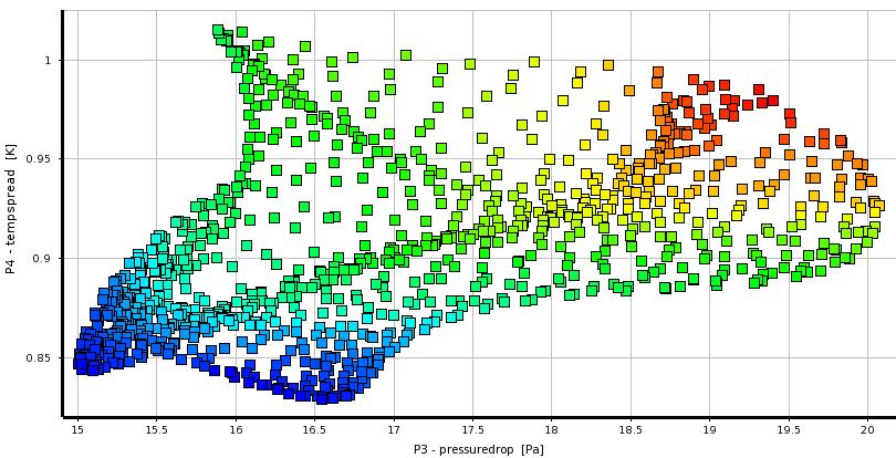
21 BAD GOOD Flow Uniformity Bad Good Slit Die Slit Die Need uniform outflow Minimize pressure drop P2 P3 P1 Pressure Drop 21


22 Combustor Combustor Diffuser Length Exit Height Outlet 3 parameters Inlet Dump Gap Outlet Outlet Minimize pressure loss Minimize mach number Sensitivity 22


23 External Aerodynamics Volvo XC60 vehicle model Four shape parameters RBF Morph to define shape parameters ANSYS DesignXplorer To drive shape parameters To create DOE To perform Goal Driven Optimization Ideal Aerodynamics Optimization Process Capacity Automatic Fast Accurate 23


 Prism Count : 24.")

24 Step #1 : Baseline Model Volume Mesh TGrid Cell Count : 50.2 Million Cells Prism Layers : 10 (First Aspect Ratio 10, Growth 1.1) Prism Count : 24.4 Million Cells Skewness < 0.9 Prism Layers Cut Plane Y=0 24 Cut Plane Z = 1.4 m

25 Step #2 : CFD Setup Boundary Conditions Inlet : Velocity Inlet 100 kmph Outlet : Pressure Outlet, 0 Pa (Gage) Side walls : Wall, no-slip Top wall : Wall, no-slip Solver Settings Steady, PBCS, Green Gauss Node Based Gradient Fluid : Incompressible air, Density = kg/m 3, Turbulence : Realizable K-epsilon, Non-equilibrium wall treatment Discretization : Pressure Standard Momentum, TKE, TDR 2 nd Order Solution Controls Courant Number = 200 ERF Momentum, Pressure = 0.75 URFs Density = 1.0, Body Forces = 1.0 TKE, TDR = 0.8 TR =


 Roof Drop")
")
26 Step #3 : RBF-Morph Note: a separate webinar looks at Fluent MMO in more detail, but this example used RBF-Morph Boat Tail Angle (P2) Roof Drop Angle (P3) 26 Green House (P4) Front Spoiler Angle (P5)


 RBF-solution can also be applied on")
27 Step #3 : RBF-Morph Fully integrated within FLUENT and Workbench Easy to use Parallel => rapidly morph large size models Mesh independent solution works with all element types (tetrahedral, hexahedral, polyhedral, etc.) Superposition of multiple RBF-solutions makes the FLUENT case truly parametric (only 1 mesh is stored) RBF-solution can also be applied on the CAD Precision: exact nodal movement and exact feature preservation. 27


28 Step #4 : Setup DesignXplorer DOE: Central Composite Design, Face Centered, Enhanced 28


29 Results : 29


30 Optimization 30
31 Results : Flow Results Discussion Design point 1, 9, 19 & 25 Velocity contours Iso-surface of total pressure = 0.0 Design Points Boat Tail Angle (P2) Long Roof Angle (P3) Green House (P4) Front Spoiler Angle (P5) Drag Force (N) (P1)


32 Design Point #19 32
33 Mesh Morphing and Optimizer 33
34 Mesh Morpher and Optimizer You pick your goal (optimization function) ANSYS FLUENT drives the optimization The mesh is morphed to the new selected shape (no remeshing) The process continues until the best shape is found 34

35 Fully Integrated Feature-No Added Cost Fully Integrated Feature in 13.0 and
36 Improvements in 14.0 New improved morphing algorithms Ability to use parameters to define objective functions Minimizes the need for UDF writing Ability to apply movement/deformation restrictions on specific surfaces Ability to plot and track the value of the objective function Ability to execute commands before or after each design iteration 36

37 Fluent Morpher-Optimization Feature Allows users to optimize product design based on shape deformation to achieve design objective Based on free-form deformation tool coupled with various optimization methods 37


38 Mesh Morphing Applies a geometric design change directly to the mesh in the solver Uses a Bernstein polynomial-based morphing scheme Freeform mesh deformation defined on a matrix of control points leads to a smooth deformation Works on all mesh types (Tet/Prism, CutCell, HexaCore, Polyhedral) User prescribes the scale and direction of deformations to control points distributed evenly through the rectilinear region. 38


39 Process What if? Setup Case Run Setup Morph Morph Evaluate OR Regions Parameters Deformation Optimizer Optimizer Setup Case Run Setup Optimizer Optimize Auto 39 Choose best design Optimal Solution


40 Example Simple Sedan Sequential Tabs Define Control Region(s) 40

 Select control")

41 Deformation Definition Define constraint(s) (if any) Select control points and prescribe the relative ranges of motion 41


42 Optimizer Algorithms; Compass, Powell, Rosenbrock, Simplex, Torczon Auto Optimize! 42


43 Results Incompressible turbulent flow Objective Function; Minimize Drag Baseline Design Optimized Design 43

44 Generic Mirror Drag Optimization Drag Optimization Initial Value ~10% Final Value 44
45 RBF Morph An Add-on Module for Mesh Morphing in ANSYS Fluent 45


46 Morphing & Smoothing A mesh morpher is a tool capable of performing mesh modifications in order to achieve arbitrary shape changes and related volume smoothing without changing the mesh topology. In general, a morphing operation can introduce a reduction of the mesh quality A good morpher has to minimize this effect, and maximize the possible shape modifications. If mesh quality is well preserved, then using the same mesh structure has massive productivity benefits 46
47 The Aim of RBF Morph The aim of RBF Morph is to perform fast mesh morphing using a meshindependent approach based on state-of-the-art RBF (Radial Basis Function) techniques. The use of RBF Morph allows the CFD user to perform shape modifications, compatible with the mesh topology, directly at the solving stage inside the Fluent Solver, by simply adding a single command line in the input file: (rbf-morph (("sol-1" amp-1) ("sol-2" amp-2)...("sol-n" amp-n))) The final goal is to perform parametric studies of component shapes and positions to find optimal configurations using: Design Changes Multi-configuration studies Sensitivity Studies DOE (Design Of Experiments) Optimization 47


48 RBF Morph Advantages Faster and more consistent than remeshing Simplifies the parameterization of models Cuts out any file i/o associated with traditional remeshing methods Fast convergence on new designs from previous results Ideal for robust design analysis or optimization Truly opens up the realms of design optimisation on large-scale CFD models where remeshing and file i/o are very expensive 48
 in a short time Management of every kind of mesh element type (tetrahedral, hexahedral,")
 Ability to convert morphed mesh surfaces back into CAD Multi fit makes the Fluent case truly parametric (only 1 mesh is stored) Precision: exact nodal movement and exact feature preservation.")
49 RBF Morph Features The user-friendly RBF Morph addon module is fully integrated within Fluent (GUI, TUI & solving stage) and Workbench Mesh-independent RBF fit used for surface mesh morphing and volume mesh smoothing Parallel calculation allows to morph large size models (many millions of cells) in a short time Management of every kind of mesh element type (tetrahedral, hexahedral, polyhedral, etc.) Ability to convert morphed mesh surfaces back into CAD Multi fit makes the Fluent case truly parametric (only 1 mesh is stored) Precision: exact nodal movement and exact feature preservation. RBF Morph allows exact prescription of surface movements which opens up several interesting capabilities, including: FEM deformed shape (static) FSI based on modal FEM analysis Target surfaces (STL) 49

50 How Does RBF-Morph work? A system of radial functions is used to fit a solution for the mesh movement/morphing, from a list of source points and their prescribed displacements Radial Basis Function interpolation is used to derive the displacement at any location in the space The RBF problem definition is mesh independent. 50

![displacements). Step 2 [SERIAL Fluent] fitting of the RBF system.](/docs-images/80/81220633/images/51-2.jpg "Step 3 [SERIAL or PARALLEL Fluent] morphing of the surface and volume mesh")
51 How it Works: The Work-Flow RBF Morph execution requires three steps: Step 1 [SERIAL Fluent] setup and definition of the problem (source points and displacements). Step 2 [SERIAL Fluent] fitting of the RBF system. Step 3 [SERIAL or PARALLEL Fluent] morphing of the surface and volume mesh (available also in the CFD solution stage). 51


52 RBF-Morph is Integrated with Fluent 52

53 Internal flow example Here, a pipe is projected onto a previously defined STL shape 53

54 Compressor Blade Example 54

55 External flow example courtesy of Ignazio Maria Viola Ship sail rotation 55

 56")
56 External Flow Example (2) 56
57 Conclusions A CFD model can be accurately moulded in a parametric manner within ANSYS Fluent using the RBF Morph Addon Module Such parametric CFD model can be easily coupled with automatic optimization tools to steer the solution to an optimal design that can then be exported into the preferred CAD platform (using STEP) The proposed approach dramatically reduces the man time required for shape optimisation set-up, thus widening the CFD calculation capability Reference: M.E. Biancolini, Mesh morphing and smoothing by means of Radial Basis Functions (RBF): a practical example using Fluent and RBF Morph in Handbook of Research on Computational Science and Engineering: Theory and Practice ( 57
58 ANSYS Fluent Adjoint Solver 58
59 Summary Key Ideas Fundamentals Adjoint equations Workflow Shape sensitivity Gradient algorithm & optimization Mesh morphing Mesh adaptation Current Functionality Features in Fluent 14 & 14.5 Examples Internal flows Robust design External flows 59
60 Key Ideas 60
61 Key Ideas - Fundamentals What does an adjoint solver do? An adjoint solver provides specific information about a fluid system that is very difficult to gather otherwise. An adjoint solver can be used to compute the derivative of an engineering quantity with respect to all of the inputs for the system. For example Derivative of drag with respect to the shape of a vehicle. Derivative of total pressure drop with respect the shape of the flow path. 61
62 Key Ideas - Fundamentals High-level system view of a conventional flow solver Inputs Boundary mesh Interior mesh Material properties Boundary condition 1 Flow angle Inlet velocity FLOW SOLVER Outputs Field data Contour plots Vector plots xy-plots Scalar values Lift Drag Total pressure drop 62
63 Key Ideas - Fundamentals HOW ARE CHANGES TO KEY OUTPUTS DEPENDENT ON CHANGES TO THE INPUTS? Inputs Boundary mesh Interior mesh Material properties Boundary condition 1 Flow angle Inlet velocity? ADJOINT SOLVER Outputs Field data Contour plots Vector plots xy-plots Scalar values Lift Drag Total pressure drop 63
64 Fundamentals Discrete or continuous adjoint? Continuous Mathematically formal. Adjoint is constructed at PDE level. Easier initial implementation. Wall functions, boundary conditions and expansion to richer physics can all be problematic. Discrete CHOSEN METHOD Numerically formal. Adjoint is constructed at the level of the discretized equations. Mechanical process to construct the adjoint somewhat challenging. Easier to test. 64
65 Key Ideas - Workflow Workflow Solve the flow equations and post-process the results as usual. Pick an observation that is of engineering interest. Lift, drag, total pressure drop? Set up and solve the adjoint problem for this observation Define solution advancement controls Set convergence criteria Initialize Iterate to convergence Post-process the adjoint solution to get Shape sensitivity Sensitivity to boundary condition settings Contour & vector plots 65
66 Key Ideas What have we learned so far? An adjoint solver can be used to compute the derivative of a chosen observation of engineering interest with respect to all the input data for the system. The adjoint equations form a linear system. Solving an adjoint problem is not trivial about as much effort as a flow solution. The adjoint solution provides guidance on the optimal adjustment that will improve a system s performance. An adjoint solution can be used to estimate the effect of a change prior to actually making the change. Shape sensitivity data can be combined with mesh morphing to guide smooth mesh deformations. An adjoint solution can be used as part of a gradient-based optimization algorithm. An adjoint solution can be used to guide mesh adaptation. 66
67 Current Functionality The adjoint solver is released with all Fluent 14 packages. Documentation is available Theory Usage Tutorial Case study Training is available Functionality is activated by Loading the adjoint solver addon module A new menu item is added at the top level. 67
68 Current Functionality ANSYS-Fluent flow solver has very broad scope Adjoint is configured to compute solutions based on some assumptions Steady, incompressible, laminar flow. Steady, incompressible, turbulent flow with standard wall functions. First-order discretization in space. Frozen turbulence. The primary flow solution does NOT need to be run with these restrictions Strong evidence that these assumptions do not undermine the utility of the adjoint solution data for engineering purposes. Fully parallelized. Gradient algorithm for shape modification Mesh morphing using control points. Adjoint-based solution adaption 68
69 Current Limitations Limitations on models Porous media MRF. These can be added in time Adjoint solver stability For some cases converging the adjoint solver can be difficult Inherently unsteady flow oscillations in aerodynamic loads can signal that the adjoint may have difficulties. Flows with strong shear of particular character Saddle point, attracting focus, attracting node Stabilization mechanism is in place. Still room for improvement here. 69
70 Examples 70
![Dp tot [Pa] 180 Elbow](/docs-images/80/81220633/images/71-1.jpg "optimization Thanks to Hauke")

71 Dp tot [Pa] 180 Elbow optimization Thanks to Hauke Reese ANSYS Germany Run [-] 71

72 180 Elbow: Optimization Loop Base design Final design 72


73 External Automotive Aerodynamics - Sedan Adjoint pressure Surface map of the drag sensitivity to shape changes 73 Surface map of the drag sensitivity to shape changes Surface map of the drag sensitivity to shape changes


74 External Automotive Aerodynamics - Sedan Adjoint pressure 74
 Baseline drag = 125.8N Expected change = -1.1N Actual change = -1.")
75 External Automotive Aerodynamics - Sedan Choose a control volume that encloses the upper part of the rear corner of the vehicle (Half vehicle) Baseline drag = 125.8N Expected change = -1.1N Actual change = -1.0N Sequence of exaggerated surface displacement vector fields 75


76 External Automotive Aerodynamics - Sedan 76
77 Conclusion Reviewed key parts of adjoint method for CFD The origin of the adjoint as a method How to interpret adjoint data How to use adjoint data in a gradient algorithm Combining mesh morphing with the adjoint Adjoint-based mesh adaptation Current Functionality Adjoint solver is a full feature in Fluent 14. GUI/TUI Documentation available Training Examples Internal flows Ductwork IC Engine Robust Design External automotive flows Drag Downforce in F1 77
RBF Morph An Add-on Module for Mesh Morphing in ANSYS Fluent
 RBF Morph An Add-on Module for Mesh Morphing in ANSYS Fluent Gilles Eggenspieler Senior Product Manager 1 Morphing & Smoothing A mesh morpher is a tool capable of performing mesh modifications in order
Mesh Morphing and the Adjoint Solver in ANSYS R14.0. Simon Pereira Laz Foley
 Mesh Morphing and the Adjoint Solver in ANSYS R14.0 Simon Pereira Laz Foley 1 Agenda Fluent Morphing-Optimization Feature RBF Morph with ANSYS DesignXplorer Adjoint Solver What does an adjoint solver do,
Shape optimisation using breakthrough technologies
 Shape optimisation using breakthrough technologies Compiled by Mike Slack Ansys Technical Services 2010 ANSYS, Inc. All rights reserved. 1 ANSYS, Inc. Proprietary Introduction Shape optimisation technologies
Optimisationfor CFD. ANSYS R14 Fluids Update Seminar. Milton Park, February 16 th, 2012 Sheffield, February 29 th, 2012 Aberdeen, March 8 th, 2012
 Optimisationfor CFD ANSYS R14 Fluids Update Seminar David Mann, ANSYS UK Ltd. Milton Park, February 16 th, 2012 Sheffield, February 29 th, 2012 Aberdeen, March 8 th, 2012 1 Agenda Optimisation Tools for
Automated Design Exploration and Optimization + HPC Best Practices
 Automated Design Exploration and Optimization + HPC Best Practices 1 Outline The Path to Robust Design ANSYS DesignXplorer Mesh Morphing and Optimizer RBF Morph Adjoint Solver HPC Best Practices 2 The
An advanced RBF Morph application: coupled CFD-CSM Aeroelastic Analysis of a Full Aircraft Model and Comparison to Experimental Data
 An advanced RBF Morph application: coupled CFD-CSM Aeroelastic Analysis of a Full Aircraft Model and Comparison to Experimental Data Dr. Marco Evangelos Biancolini Tor Vergata University, Rome, Italy Dr.
Design Exploration and Robust Design. Judd Kaiser Product Manager, ANSYS Workbench Platform
 Design Exploration and Robust Design Judd Kaiser Product Manager, ANSYS Workbench Platform 1 Agenda 2 What is Robust Design? At ANSYS Workbench Principles DesignXplorer ANSYS Vision What is Robust Design?
Adjoint Solver Workshop
 Adjoint Solver Workshop Why is an Adjoint Solver useful? Design and manufacture for better performance: e.g. airfoil, combustor, rotor blade, ducts, body shape, etc. by optimising a certain characteristic
Coupled Analysis of FSI
 Coupled Analysis of FSI Qin Yin Fan Oct. 11, 2008 Important Key Words Fluid Structure Interface = FSI Computational Fluid Dynamics = CFD Pressure Displacement Analysis = PDA Thermal Stress Analysis = TSA
RBF Morph: mesh morphing in OpenFoam
 RBF Morph: mesh morphing in OpenFoam Dr. Marco Evangelos Biancolini University of Rome Tor Vergata @ CINECA, 26-28 March 2014 Cineca - BOLOGNA RBF Morph Training PRACE School 2013 Session #1 General Introduction
ANSYS AIM 16.0 Overview. AIM Program Management
 1 2015 ANSYS, Inc. September 27, 2015 ANSYS AIM 16.0 Overview AIM Program Management 2 2015 ANSYS, Inc. September 27, 2015 Today s Simulation Challenges Leveraging simulation across engineering organizations
Aero-Vibro Acoustics For Wind Noise Application. David Roche and Ashok Khondge ANSYS, Inc.
 Aero-Vibro Acoustics For Wind Noise Application David Roche and Ashok Khondge ANSYS, Inc. Outline 1. Wind Noise 2. Problem Description 3. Simulation Methodology 4. Results 5. Summary Thursday, October
NUMERICAL INVESTIGATION OF THE FLOW BEHAVIOR INTO THE INLET GUIDE VANE SYSTEM (IGV)
") University of West Bohemia» Department of Power System Engineering NUMERICAL INVESTIGATION OF THE FLOW BEHAVIOR INTO THE INLET GUIDE VANE SYSTEM (IGV) Publication was supported by project: Budování excelentního
University of West Bohemia» Department of Power System Engineering NUMERICAL INVESTIGATION OF THE FLOW BEHAVIOR INTO THE INLET GUIDE VANE SYSTEM (IGV) Publication was supported by project: Budování excelentního
ANSYS Fluid Structure Interaction for Thermal Management and Aeroelasticity
 ANSYS Fluid Structure Interaction for Thermal Management and Aeroelasticity Phil Stopford Duxford Air Museum 11th May 2011 2011 2010 ANSYS, Inc. All rights reserved. 1 ANSYS, Inc. Proprietary Fluid Structure
Calculate a solution using the pressure-based coupled solver.
 Tutorial 19. Modeling Cavitation Introduction This tutorial examines the pressure-driven cavitating flow of water through a sharpedged orifice. This is a typical configuration in fuel injectors, and brings
Shape Optimization for Aerodynamic Efficiency Using Adjoint Methods
 White Paper Shape Optimization for Aerodynamic Efficiency Using Adjoint Methods Adjoint solvers take a Computational Fluid Dynamics (CFD) flow solution and calculate the sensitivity of performance indicators
Aerodynamic Study of a Realistic Car W. TOUGERON
 Aerodynamic Study of a Realistic Car W. TOUGERON Tougeron CFD Engineer 2016 Abstract This document presents an aerodynamic CFD study of a realistic car geometry. The aim is to demonstrate the efficiency
Tutorial: Simulating a 3D Check Valve Using Dynamic Mesh 6DOF Model And Diffusion Smoothing
 Tutorial: Simulating a 3D Check Valve Using Dynamic Mesh 6DOF Model And Diffusion Smoothing Introduction The purpose of this tutorial is to demonstrate how to simulate a ball check valve with small displacement
Overview and Recent Developments of Dynamic Mesh Capabilities
 Overview and Recent Developments of Dynamic Mesh Capabilities Henrik Rusche and Hrvoje Jasak h.rusche@wikki-gmbh.de and h.jasak@wikki.co.uk Wikki Gmbh, Germany Wikki Ltd, United Kingdom 6th OpenFOAM Workshop,
Auto Injector Syringe. A Fluent Dynamic Mesh 1DOF Tutorial
 Auto Injector Syringe A Fluent Dynamic Mesh 1DOF Tutorial 1 2015 ANSYS, Inc. June 26, 2015 Prerequisites This tutorial is written with the assumption that You have attended the Introduction to ANSYS Fluent
Adjoint Solver Advances, Tailored to Automotive Applications
 Adjoint Solver Advances, Tailored to Automotive Applications Stamatina Petropoulou s.petropoulou@iconcfd.com 1 Contents 1. Icon s Principal Work in FlowHead 2. Demonstration Cases 3. Icon s Further Development
Topology Optimization in Fluid Dynamics
 A Methodology for Topology Optimization in Fluid Dynamics 1 Chris Cowan Ozen Engineering, Inc. 1210 E. Arques Ave, Suite 207 Sunnyvale, CA 94085 info@ozeninc.com Ozen Engineering Inc. We are your local
Verification of Laminar and Validation of Turbulent Pipe Flows
 1 Verification of Laminar and Validation of Turbulent Pipe Flows 1. Purpose ME:5160 Intermediate Mechanics of Fluids CFD LAB 1 (ANSYS 18.1; Last Updated: Aug. 1, 2017) By Timur Dogan, Michael Conger, Dong-Hwan
Compressible Flow in a Nozzle
 SPC 407 Supersonic & Hypersonic Fluid Dynamics Ansys Fluent Tutorial 1 Compressible Flow in a Nozzle Ahmed M Nagib Elmekawy, PhD, P.E. Problem Specification Consider air flowing at high-speed through a
Automotive Fluid-Structure Interaction (FSI) Concepts, Solutions and Applications. Laz Foley, ANSYS Inc.
 Concepts, Solutions and Applications. Laz Foley, ANSYS Inc.") Automotive Fluid-Structure Interaction (FSI) Concepts, Solutions and Applications Laz Foley, ANSYS Inc. Outline FSI Classifications FSI Solutions FSI Modeling Approaches ANSYS Workbench for FSI System
Automotive Fluid-Structure Interaction (FSI) Concepts, Solutions and Applications Laz Foley, ANSYS Inc. Outline FSI Classifications FSI Solutions FSI Modeling Approaches ANSYS Workbench for FSI System
Applications of ICFD solver by LS-DYNA in Automotive Fields to Solve Fluid-Solid-Interaction (FSI) Problems
 Problems") Applications of ICFD solver by LS-DYNA in Automotive Fields to Solve Fluid-Solid-Interaction (FSI) Problems George Wang(1 ), Facundo del Pin(2), Inaki Caldichoury (2), Prince Rodriguez(3), Jason Tippie
Applications of ICFD solver by LS-DYNA in Automotive Fields to Solve Fluid-Solid-Interaction (FSI) Problems George Wang(1 ), Facundo del Pin(2), Inaki Caldichoury (2), Prince Rodriguez(3), Jason Tippie
CFD MODELING FOR PNEUMATIC CONVEYING
 CFD MODELING FOR PNEUMATIC CONVEYING Arvind Kumar 1, D.R. Kaushal 2, Navneet Kumar 3 1 Associate Professor YMCAUST, Faridabad 2 Associate Professor, IIT, Delhi 3 Research Scholar IIT, Delhi e-mail: arvindeem@yahoo.co.in
Using a Single Rotating Reference Frame
 Tutorial 9. Using a Single Rotating Reference Frame Introduction This tutorial considers the flow within a 2D, axisymmetric, co-rotating disk cavity system. Understanding the behavior of such flows is
Accurate and Efficient Turbomachinery Simulation. Chad Custer, PhD Turbomachinery Technical Specialist
 Accurate and Efficient Turbomachinery Simulation Chad Custer, PhD Turbomachinery Technical Specialist Outline Turbomachinery simulation advantages Axial fan optimization Description of design objectives
DrivAer-Aerodynamic Investigations for a New Realistic Generic Car Model using ANSYS CFD
 DrivAer-Aerodynamic Investigations for a New Realistic Generic Car Model using ANSYS CFD Thomas Frank (*), BenediktGerlicher (*), Juan Abanto (**) (*) ANSYS Germany, Otterfing, Germany (**) ANSYS Inc.,
Introduction to ANSYS CFX
 Workshop 03 Fluid flow around the NACA0012 Airfoil 16.0 Release Introduction to ANSYS CFX 2015 ANSYS, Inc. March 13, 2015 1 Release 16.0 Workshop Description: The flow simulated is an external aerodynamics
Speed and Accuracy of CFD: Achieving Both Successfully ANSYS UK S.A.Silvester
 Speed and Accuracy of CFD: Achieving Both Successfully ANSYS UK S.A.Silvester 2010 ANSYS, Inc. All rights reserved. 1 ANSYS, Inc. Proprietary Content ANSYS CFD Introduction ANSYS, the company Simulation
CFD Topological Optimization of a Car Water-Pump Inlet using TOSCA Fluid and STAR- CCM+
 CFD Topological Optimization of a Car Water-Pump Inlet using TOSCA Fluid and STAR- CCM+ Dr. Anselm Hopf Dr. Andrew Hitchings Les Routledge Ford Motor Company CONTENTS Introduction/Motivation Optimization
Introduction to CFX. Workshop 2. Transonic Flow Over a NACA 0012 Airfoil. WS2-1. ANSYS, Inc. Proprietary 2009 ANSYS, Inc. All rights reserved.
 Workshop 2 Transonic Flow Over a NACA 0012 Airfoil. Introduction to CFX WS2-1 Goals The purpose of this tutorial is to introduce the user to modelling flow in high speed external aerodynamic applications.
Ansys Fluent R Michele Andreoli
 Ansys Fluent R 17.0 Michele Andreoli (m.andreoli@enginsoft.it) Table of contents User Interface Fluent Meshing Solver Numerics New features Innovative Solutions New User Interface: Ribbon-Driven Solver
Parametric. Practices. Patrick Cunningham. CAE Associates Inc. and ANSYS Inc. Proprietary 2012 CAE Associates Inc. and ANSYS Inc. All rights reserved.
 Parametric Modeling Best Practices Patrick Cunningham July, 2012 CAE Associates Inc. and ANSYS Inc. Proprietary 2012 CAE Associates Inc. and ANSYS Inc. All rights reserved. E-Learning Webinar Series This
Simulation of Flow Development in a Pipe
 Tutorial 4. Simulation of Flow Development in a Pipe Introduction The purpose of this tutorial is to illustrate the setup and solution of a 3D turbulent fluid flow in a pipe. The pipe networks are common
This tutorial illustrates how to set up and solve a problem involving solidification. This tutorial will demonstrate how to do the following:
 Tutorial 22. Modeling Solidification Introduction This tutorial illustrates how to set up and solve a problem involving solidification. This tutorial will demonstrate how to do the following: Define a
Simulating Sinkage & Trim for Planing Boat Hulls. A Fluent Dynamic Mesh 6DOF Tutorial
 Simulating Sinkage & Trim for Planing Boat Hulls A Fluent Dynamic Mesh 6DOF Tutorial 1 Introduction Workshop Description This workshop describes how to perform a transient 2DOF simulation of a planing
Open source software tools for powertrain optimisation
 Open source software tools for powertrain optimisation Paolo Geremia Eugene de Villiers TWO-DAY MEETING ON INTERNAL COMBUSTION ENGINE SIMULATIONS USING OPENFOAM TECHNOLOGY 11-12 July, 2011 info@engys.eu
A B C D E. Settings Choose height, H, free stream velocity, U, and fluid (dynamic viscosity and density ) so that: Reynolds number
 so that: Reynolds number") Individual task Objective To derive the drag coefficient for a 2D object, defined as where D (N/m) is the aerodynamic drag force (per unit length in the third direction) acting on the object. The object
Individual task Objective To derive the drag coefficient for a 2D object, defined as where D (N/m) is the aerodynamic drag force (per unit length in the third direction) acting on the object. The object
TryItNow! Step by Step Walkthrough: Spoiler Support
 TryItNow! Step by Step Walkthrough: Spoiler Support 1 2015 ANSYS, Inc. March 28, 2016 TryItNow! Step by Step Walkthrough: Spoiler Support ANSYS designed this TryItNow! experience to give you quick access
midas NFX 2017R1 Release Note
 Total Solution for True Analysis-driven Design midas NFX 2017R1 Release Note 1 midas NFX R E L E A S E N O T E 2 0 1 7 R 1 Major Improvements Midas NFX is an integrated finite element analysis program
Introduction to C omputational F luid Dynamics. D. Murrin
 Introduction to C omputational F luid Dynamics D. Murrin Computational fluid dynamics (CFD) is the science of predicting fluid flow, heat transfer, mass transfer, chemical reactions, and related phenomena
CFD Topology Optimization of Automotive Components
 CFD Topology Optimization of Automotive Components Dr.-Ing. Markus Stephan, Dr.-Ing. Dipl.-Phys. Pascal Häußler, Dipl.-Math. Michael Böhm FE-DESIGN GmbH, Karlsruhe, Germany Synopsis Automatic CFD optimization
Simulation of Laminar Pipe Flows
 Simulation of Laminar Pipe Flows 57:020 Mechanics of Fluids and Transport Processes CFD PRELAB 1 By Timur Dogan, Michael Conger, Maysam Mousaviraad, Tao Xing and Fred Stern IIHR-Hydroscience & Engineering
Verification and Validation of Turbulent Flow around a Clark-Y Airfoil
 Verification and Validation of Turbulent Flow around a Clark-Y Airfoil 1. Purpose 58:160 Intermediate Mechanics of Fluids CFD LAB 2 By Tao Xing and Fred Stern IIHR-Hydroscience & Engineering The University
Modeling Supersonic Jet Screech Noise Using Direct Computational Aeroacoustics (CAA) 14.5 Release
 14.5 Release") Modeling Supersonic Jet Screech Noise Using Direct Computational Aeroacoustics (CAA) 14.5 Release 2011 ANSYS, Inc. November 7, 2012 1 Workshop Advanced ANSYS FLUENT Acoustics Introduction This tutorial
Modeling Supersonic Jet Screech Noise Using Direct Computational Aeroacoustics (CAA) 14.5 Release 2011 ANSYS, Inc. November 7, 2012 1 Workshop Advanced ANSYS FLUENT Acoustics Introduction This tutorial
Using Multiple Rotating Reference Frames
 Tutorial 10. Using Multiple Rotating Reference Frames Introduction Many engineering problems involve rotating flow domains. One example is the centrifugal blower unit that is typically used in automotive
Simulation and Optimization in the wind energy industry
 Simulation and Optimization in the wind energy industry Numerical Simulation & Optimization www.ozeninc.com/optimization optimization@ozeninc.com Summary Why to use numerical simulations and optimization?
Modeling External Compressible Flow
 Tutorial 3. Modeling External Compressible Flow Introduction The purpose of this tutorial is to compute the turbulent flow past a transonic airfoil at a nonzero angle of attack. You will use the Spalart-Allmaras
Flow and Heat Transfer in a Mixing Elbow
 Flow and Heat Transfer in a Mixing Elbow Objectives The main objectives of the project are to learn (i) how to set up and perform flow simulations with heat transfer and mixing, (ii) post-processing and
Adjoint Optimization combined with mesh morphing for CFD applications
 Adjoint Optimization combined with mesh morphing for CFD applications Alberto Clarich*, Luca Battaglia*, Enrico Nobile**, Marco Evangelos Biancolini, Ubaldo Cella *ESTECO Spa, Italy. Email: engineering@esteco.com
Strategies to Achieve Reliable and Accurate CFD Solutions
 Strategies to Achieve Reliable and Accurate CFD Solutions Mark Keating ANSYS UK 2010 ANSYS, Inc. All rights reserved. 1 ANSYS, Inc. Proprietary Agenda Why develop a CFD strategy? Pre-Processing Strategies
CFD Simulation of a dry Scroll Vacuum Pump including Leakage Flows
 CFD Simulation of a dry Scroll Vacuum Pump including Leakage Flows Jan Hesse, Rainer Andres CFX Berlin Software GmbH, Berlin, Germany 1 Introduction Numerical simulation results of a dry scroll vacuum
Problem description. The FCBI-C element is used in the fluid part of the model.
 Problem description This tutorial illustrates the use of ADINA for analyzing the fluid-structure interaction (FSI) behavior of a flexible splitter behind a 2D cylinder and the surrounding fluid in a channel.
Fluid structure interaction analysis: vortex shedding induced vibrations
 Fluid structure interaction analysis: vortex shedding induced vibrations N. Di Domenico, M. E. * University of Rome «Tor Vergata», Department of Enterprise Engineering «Mario Lucertini» A. Wade, T. Berg,
Axial Fan Optimization Workflow
 Axial Fan Optimization Workflow Turbomachinery design optimization using TCFD and CAESES Radek Máca, PhD Head CFD Engineer CFD Support radek.maca@cfdsupport.com Ceyhan Erdem Project and Support Engineer
Introduction to ANSYS DesignXplorer
 Overview 14. 5 Release Introduction to ANSYS DesignXplorer 1 2013 ANSYS, Inc. September 27, 2013 What is DesignXplorer? DesignXplorer (DX) is a tool that uses response surfaces and direct optimization
System Level Cooling, Fatigue, and Durability. Co-Simulation. Stuart A. Walker, Ph.D.
 System Level Cooling, Fatigue, and Durability Analysis via Multiphysics Co-Simulation Stuart A. Walker, Ph.D. swalker@altair.com Outline Motivation Presentation of process Presentation of tools Presentation
KEYWORDS Morphing, CAE workflow, Optimization, Automation, DOE, Regression, CFD, FEM, Python
 DESIGN OPTIMIZATION WITH ANSA MORPH 1 Tobias Eidevåg *, 1 David Tarazona Ramos *, 1 Mohammad El-Alti 1 Alten AB, Sweden KEYWORDS Morphing, CAE workflow, Optimization, Automation, DOE, Regression, CFD,
Self-Cultivation System
 Development of a Microorganism Incubator using CFD Simulations Self-Cultivation System A comfortable mixing incubator to grow microorganism for agricultural, animal husbandry and ocean agriculture industries
Thank you for downloading one of our ANSYS whitepapers we hope you enjoy it.
 Thank you! Thank you for downloading one of our ANSYS whitepapers we hope you enjoy it. Have questions? Need more information? Please don t hesitate to contact us! We have plenty more where this came from.
Using Multiple Rotating Reference Frames
 Tutorial 9. Using Multiple Rotating Reference Frames Introduction Many engineering problems involve rotating flow domains. One example is the centrifugal blower unit that is typically used in automotive
Use of CFD in Design and Development of R404A Reciprocating Compressor
 Purdue University Purdue e-pubs International Compressor Engineering Conference School of Mechanical Engineering 2006 Use of CFD in Design and Development of R404A Reciprocating Compressor Yogesh V. Birari
Study Of Overloading Effects, In A Refrigerated Display Case
 Study Of Overloading Effects, In A Refrigerated Display Case Sandeep Palaksha Senior CAE Engineer HUSSMANN Basavanagudi Bangalore 04, India p.sandeep@hussmann.com Narasimhamurthy CAE Engineer HUSSMANN
Backward facing step Homework. Department of Fluid Mechanics. For Personal Use. Budapest University of Technology and Economics. Budapest, 2010 autumn
 Backward facing step Homework Department of Fluid Mechanics Budapest University of Technology and Economics Budapest, 2010 autumn Updated: October 26, 2010 CONTENTS i Contents 1 Introduction 1 2 The problem
Fast Radial Basis Functions for Engineering Applications. Prof. Marco Evangelos Biancolini University of Rome Tor Vergata
 Fast Radial Basis Functions for Engineering Applications Prof. Marco Evangelos Biancolini University of Rome Tor Vergata Outline 2 RBF background Fast RBF on HPC Engineering Applications Mesh morphing
ANSYS AIM Tutorial Compressible Flow in a Nozzle
 ANSYS AIM Tutorial Compressible Flow in a Nozzle Author(s): Sebastian Vecchi Created using ANSYS AIM 18.1 Problem Specification Pre-Analysis & Start Up Pre-Analysis Start-Up Geometry Import Geometry Mesh
Computational Study of Laminar Flowfield around a Square Cylinder using Ansys Fluent
 MEGR 7090-003, Computational Fluid Dynamics :1 7 Spring 2015 Computational Study of Laminar Flowfield around a Square Cylinder using Ansys Fluent Rahul R Upadhyay Master of Science, Dept of Mechanical
STAR-CCM+ User Guide 6922
 STAR-CCM+ User Guide 6922 Introduction Welcome to the STAR-CCM+ introductory tutorial. In this tutorial, you explore the important concepts and workflow. Complete this tutorial before attempting any others.
Modeling Unsteady Compressible Flow
 Tutorial 4. Modeling Unsteady Compressible Flow Introduction In this tutorial, FLUENT s density-based implicit solver is used to predict the timedependent flow through a two-dimensional nozzle. As an initial
Turbocharger Design & Analysis Solutions. Bill Holmes Brad Hutchinson Detroit, October 2012
 Turbocharger Design & Analysis Solutions Bill Holmes Brad Hutchinson Detroit, October 2012 Agenda ANSYS overview ANSYS TurboSystem Blade row solutions The ANSYS Transformation methods An example: turbocharger
Express Introductory Training in ANSYS Fluent Workshop 06 Using Moving Reference Frames and Sliding Meshes
 Express Introductory Training in ANSYS Fluent Workshop 06 Using Moving Reference Frames and Sliding Meshes Dimitrios Sofialidis Technical Manager, SimTec Ltd. Mechanical Engineer, PhD PRACE Autumn School
The viscous forces on the cylinder are proportional to the gradient of the velocity field at the
 Fluid Dynamics Models : Flow Past a Cylinder Flow Past a Cylinder Introduction The flow of fluid behind a blunt body such as an automobile is difficult to compute due to the unsteady flows. The wake behind
Use 6DOF solver to calculate motion of the moving body. Create TIFF files for graphic visualization of the solution.
 Introduction The purpose of this tutorial is to provide guidelines and recommendations for setting up and solving a moving deforming mesh (MDM) case along with the six degree of freedom (6DOF) solver and
High-Lift Aerodynamics: STAR-CCM+ Applied to AIAA HiLiftWS1 D. Snyder
 High-Lift Aerodynamics: STAR-CCM+ Applied to AIAA HiLiftWS1 D. Snyder Aerospace Application Areas Aerodynamics Subsonic through Hypersonic Aeroacoustics Store release & weapons bay analysis High lift devices
Simulation of In-Cylinder Flow Phenomena with ANSYS Piston Grid An Improved Meshing and Simulation Approach
 Simulation of In-Cylinder Flow Phenomena with ANSYS Piston Grid An Improved Meshing and Simulation Approach Dipl.-Ing. (FH) Günther Lang, CFDnetwork Engineering Dipl.-Ing. Burkhard Lewerich, CFDnetwork
McNair Scholars Research Journal
 McNair Scholars Research Journal Volume 2 Article 1 2015 Benchmarking of Computational Models against Experimental Data for Velocity Profile Effects on CFD Analysis of Adiabatic Film-Cooling Effectiveness
Simulation and Validation of Turbulent Pipe Flows
 Simulation and Validation of Turbulent Pipe Flows ENGR:2510 Mechanics of Fluids and Transport Processes CFD LAB 1 (ANSYS 17.1; Last Updated: Oct. 10, 2016) By Timur Dogan, Michael Conger, Dong-Hwan Kim,
Supersonic Flow Over a Wedge
 SPC 407 Supersonic & Hypersonic Fluid Dynamics Ansys Fluent Tutorial 2 Supersonic Flow Over a Wedge Ahmed M Nagib Elmekawy, PhD, P.E. Problem Specification A uniform supersonic stream encounters a wedge
Application of Wray-Agarwal Turbulence Model for Accurate Numerical Simulation of Flow Past a Three-Dimensional Wing-body
 Washington University in St. Louis Washington University Open Scholarship Mechanical Engineering and Materials Science Independent Study Mechanical Engineering & Materials Science 4-28-2016 Application
I. Introduction. Optimization Algorithm Components. Abstract for the 5 th OpenFOAM User Conference 2017, Wiesbaden - Germany
 An Aerodynamic Optimization Framework for the Automotive Industry, based on Continuous Adjoint and OpenFOAM E. Papoutsis-Kiachagias 1, V. Asouti 1, K. Giannakoglou 1, K. Gkagkas 2 1) National Technical
Webinar: TwinMesh for Reliable CFD Analysis of Rotating Positive Displacement Machines
 Webinar: TwinMesh for Reliable CFD Analysis of Rotating Positive Displacement Machines 14.07.2015 Dipl.-Ing. Jan Hesse Jan.hesse@cfx-berlin.de CFX Berlin Software GmbH Karl-Marx-Allee 90 A 10243 Berlin
Volute Optimization Workflow
 Volute Optimization Workflow Volute design optimization with CAESES, Grid Pro, and TCFD Mattia Brenner Head of Sales Europe FRIENDSHIP SYSTEMS AG brenner@friendship-systems.com Samuel E James Director
Rotating Moving Boundary Analysis Using ANSYS 5.7
 Abstract Rotating Moving Boundary Analysis Using ANSYS 5.7 Qin Yin Fan CYBERNET SYSTEMS CO., LTD. Rich Lange ANSYS Inc. As subroutines in commercial software, APDL (ANSYS Parametric Design Language) provides
CHAPTER 8 FINITE ELEMENT ANALYSIS
 If you have any questions about this tutorial, feel free to contact Wenjin Tao (w.tao@mst.edu). CHAPTER 8 FINITE ELEMENT ANALYSIS Finite Element Analysis (FEA) is a practical application of the Finite
Lecture 7: Mesh Quality & Advanced Topics. Introduction to ANSYS Meshing Release ANSYS, Inc. February 12, 2015
 Lecture 7: Mesh Quality & Advanced Topics 15.0 Release Introduction to ANSYS Meshing 1 2015 ANSYS, Inc. February 12, 2015 Overview In this lecture we will learn: Impact of the Mesh Quality on the Solution
ANSYS FLUENT. Lecture 3. Basic Overview of Using the FLUENT User Interface L3-1. Customer Training Material
 Lecture 3 Basic Overview of Using the FLUENT User Interface Introduction to ANSYS FLUENT L3-1 Parallel Processing FLUENT can readily be run across many processors in parallel. This will greatly speed up
Workshop 3: Cutcell Mesh Generation. Introduction to ANSYS Fluent Meshing Release. Release ANSYS, Inc.
 Workshop 3: Cutcell Mesh Generation 14.5 Release Introduction to ANSYS Fluent Meshing 1 2011 ANSYS, Inc. December 21, 2012 I Introduction Workshop Description: CutCell meshing is a general purpose meshing
STAR-CCM+: Ventilation SPRING Notes on the software 2. Assigned exercise (submission via Blackboard; deadline: Thursday Week 9, 11 pm)
") STAR-CCM+: Ventilation SPRING 208. Notes on the software 2. Assigned exercise (submission via Blackboard; deadline: Thursday Week 9, pm). Features of the Exercise Natural ventilation driven by localised
STAR-CCM+: Ventilation SPRING 208. Notes on the software 2. Assigned exercise (submission via Blackboard; deadline: Thursday Week 9, pm). Features of the Exercise Natural ventilation driven by localised
Analysis of low cycle fatigue considering geometric manufacturing tolerances
 presented at the 14th Weimar Optimization and Stochastic Days 2017 Source: www.dynardo.de/en/library Analysis of low cycle fatigue considering geometric manufacturing tolerances SIEMENS AG applies ANSYS,
Commercial Implementations of Optimization Software and its Application to Fluid Dynamics Problems
 Commercial Implementations of Optimization Software and its Application to Fluid Dynamics Problems Szymon Buhajczuk, M.A.Sc SimuTech Group Toronto Fields Institute Optimization Seminar December 6, 2011
Swapnil Nimse Project 1 Challenge #2
 Swapnil Nimse Project 1 Challenge #2 Project Overview: Using Ansys-Fluent, analyze dependency of the steady-state temperature at different parts of the system on the flow velocity at the inlet and buoyancy-driven
Lab 9: FLUENT: Transient Natural Convection Between Concentric Cylinders
 Lab 9: FLUENT: Transient Natural Convection Between Concentric Cylinders Objective: The objective of this laboratory is to introduce how to use FLUENT to solve both transient and natural convection problems.
Metafor FE Software. 2. Operator split. 4. Rezoning methods 5. Contact with friction
 ALE simulations ua sus using Metafor eao 1. Introduction 2. Operator split 3. Convection schemes 4. Rezoning methods 5. Contact with friction 1 Introduction EULERIAN FORMALISM Undistorted mesh Ideal for
Impact of STAR-CCM+ v7.0 in the Automotive Industry Frederick J. Ross, CD-adapco Director, Ground Transportation
 Impact of STAR-CCM+ v7.0 in the Automotive Industry Frederick J. Ross, CD-adapco Director, Ground Transportation Vehicle Simulation Components Vehicle Aerodynamics Design Studies Aeroacoustics Water/Dirt
First Steps - Ball Valve Design
 COSMOSFloWorks 2004 Tutorial 1 First Steps - Ball Valve Design This First Steps tutorial covers the flow of water through a ball valve assembly before and after some design changes. The objective is to
RAPID DESIGN AND FLOW SIMULATIONS FOR TUBOCHARGER COMPONENTS
 EASC ANSYS Conference 2009 RAPID DESIGN AND FLOW SIMULATIONS FOR TUBOCHARGER COMPONENTS Authors Dipl.-Ing. Jonas Belz Dipl.-Ing. Ralph-Peter Müller CFDnetwork Engineering CFturbo Software & Engineering
Solution Recording and Playback: Vortex Shedding
 STAR-CCM+ User Guide 6663 Solution Recording and Playback: Vortex Shedding This tutorial demonstrates how to use the solution recording and playback module for capturing the results of transient phenomena.