CODE Analysis, design, production control of thin films
|
|
|
- Emery Dalton
- 5 years ago
- Views:
Transcription

1 M.Theiss Hard- and Software for Optical Spectroscopy Dr.-Bernhard-Klein-Str. 110, D Aachen Phone: (49) Fax: (49) Web: CODE Analysis, design, production control of thin films by Wolfgang Theiss All rights reserved. No parts of this work may be reproduced in any form or by any means - graphic, electronic, or mechanical, including photocopying, recording, taping, or information storage and retrieval systems - without the written permission of the publisher. Products that are referred to in this document may be either trademarks and/or registered trademarks of the respective owners. The publisher and the author make no claim to these trademarks. While every precaution has been taken in the preparation of this document, the publisher and the author assume no responsibility for errors or omissions, or for damages resulting from the use of information contained in this document or from the use of programs and source code that may accompany it. In no event shall the publisher and the author be liable for any loss of profit or any other commercial damage caused or alleged to have been caused directly or indirectly by this document. Printed: , 23:52 in Aachen, Germany
2 Developing optical production control methods for SCOUT Contents I Table of Contents Foreword 2 Part I Overview 3 1 The company The talk The software... 4 Part II Customized views 4 Part III Optical model 5 1 Material constants... 5 Optical constants:... Overview 5 Interband transitions... 6 Vibrational... modes 8 Charge carriers... 9 Master model Layer stacks Computation... of reflectance and transmittance 11 Coherent/incoherent... superposition 12 What is the... correct layer stack? 13 3 Spectrum... types 17 Part IV Computation of technical data 18 Part V Remote control by OLE automation 20 Part VI Batch processing 20 Part VII Analysis and design 22 1 Fit strategy Examples Design Part VIII Production control schemes Part IX Program development, training, consultance work Index
3 Foreword This document gives a short summary of several talks and documents about spectrum simulation. All the pictures are just screen shots, not prepared explicitly for this document. In between the pictures there are comments that should guide you from slide to slide. Most of the slides in the talks are interactive pictures: You can vary slider positions and see what happens to the spectra. Unfortunately, in this static document these dynamical impressions cannot be reproduced. In the graphs displaying optical constants the real part is drawn blue, the imaginary one is given in red. In the case of spectrum fits, the measured spectra are always in red, the simulated spectra in blue. All simulations have been performed with our SCOUT, CODE and SPRAY software products which are commercially available. Aachen, March 2004


4 1 Overview 1.1 The company 1.2 The talk Overview 3


5 1.3 The software 2 Customized views Overview 4 The appearance of the main window is defined by so-called views (user-defined):


6 3 Optical model 3.1 Material constants Optical constants: Overview Optical model 5 Three basic types of excitations determine the optical constants of almost all materials:


7 3.1.2 Optical model 6 Interband transitions Interband transitions of cystalline materials can be descibed using the Tauc-Lorentz model: Here is a typical example using the superposition of 8 interband transitions: Amorphous materials have less rich featured, broad interband transitions which can often be described in good quality using a single OJL model:


8 Optical model 7 The theory behind the OJL model is summarized in the following page: Here is an example of a succesful application of the OJL model:

9 3.1.3 Optical model 8 Vibrational modes Vibrational modes and some electronic interband transitions can be modeled using oscillator terms. The simplest approach is the harmonic oscillator which leads to a Lorentzian line shape of the absorption band: However, in most cases a Gaussian line shape is more realistic. In SCOUT and CODE this can be obtained using Kim oscillators:


10 3.1.4 Optical model 9 Charge carriers The interaction of free charge carriers like electrons or holes can be described with the Drude model. This model has two parameters only: The plasma frequency is proportional to the square root of the carrier density, the damping constant to the inverse of the mobility. Characteristic for the presence of many charge carriers (like in metals) is the large imaginary part of the refractive index. If it is larger than the real part, no wave propagation is possible in the material. This leads to a 'rejection' of incoming waves, i.e. to a high reflectance. Radiation penetrating a metal is absorbed very efficiently in a very thin film. The following example shows that the simple Drude model does not always perform excellently:

11 Optical model 10 In cases like this you can try an extension of the Drude model which features a frequencydependent damping constant. Electron scattering at charged donor or acceptor atoms may lead to a characteristic frequency dependence of the damping constant in the Drude model: Master model Sometimes the optical constants of a material vary systematically with a compositional parameter like oxygen content in a non-stochiometric oxide or the concentration of an atomic species in a ternary system. This can be described conveniently in SCOUT and CODE using so-called master models which provide for every parameter a user-defined formula to express its dependence on the master quantity:


12 3.2 Layer stacks Computation of reflectance and transmittance Optical model 11 Single layer treatment using geometric series: Multilayers are processed applying the single layer expressions many times:


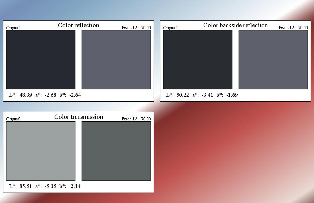
13 3.2.2 Optical model 12 Coherent/incoherent superposition CODE has a very efficient algorithm to compute R and T of partially coherent superposition of waves: For thick layers the incoherent contributions to R and T can be computed individually. Red curve in the following graph: All reflection orders superimposed. Blue curve: Backside reflection only:


14 3.2.3 Optical model 13 What is the correct layer stack? Example: The next graphs show the influence of the introduction of a surface layer to the results of a `single layer analysis. It is not easy to decide if the differences are significant if the roughness is always the same. However, if the roughness changes from sample to sample it should definitely be part of the model and part of the exported results.

15 Optical model 14

16 Optical model 15 Here is another example: A customer asked for the optical constants of a single layer deposited on glass with a sputtering device. It turned out that even advanced optical constant models could not describe the optical properties of the layer properly. Only introducing a depth inhomogeneity (and a surface layer) could solve the problem:

17 Optical model 16 Communication with the producer finally verified the assumptions made in the successful fit:


18 3.3 Optical model 17 Spectrum types


19 4 Computation of technical data 18 Computation of technical data

20 Computation of technical data 19


21 5 Remote control by OLE automation 20 Remote control by OLE automation The Excel example shows how spectra can be sent to SCOUT which are then automatically fitted. The results are passed back to an Excel worksheet. 6 Batch processing CODE can analyze series of input spectra automatically in a batch process. Enter the filenames and the import filter to be used and start the batch fit operation in the batch control window:


22 Batch processing 21 The results can be displayed directly in a view:

23 7 Analysis and design 7.1 Fit strategy Analysis and design 22 Once the optical model is ready, one must be decide which parameters may vary from sample to sample. These parameters must be determined following a fit strategy that leads to stable and reproducible results in the specified time frame. Multiple parameter optimization is a common problem of numerical mathematics. One of the main issues is to avoid that algorithms get stuck in local minima of the fit deviation. Methods like simulated annealing or genetic algorithms which overcome the local minimum problem are much too slow to be used for production control. Here is an example of a SCOUT fit running into a local fit deviation minimum: A start value of the layer thickness far away from the correct value drove the model into the wrong interference fringe order.
24 Analysis and design 23 Using the 'grid fit' feature of SCOUT this problem can be overcome very efficiently: Before the multiple parameter fit is started, the right fringe order is found by trying several thickness values (equally spaced in a user-defined thickness range) and taking the best result as starting value for the thickness. In many cases advanced fit strategies using so-called fit parameter sets are successful: Separate the fit parameters into groups which are optimized one after the other. You can, for example, fit the thickness and the refractive index of a material in a spectral region where the layer is transparent. Then freeze the parameters, and determine bandgap and other interband parameters in a spectral range with strong absorption. Then, in a final step, all parameters are optimized using the full width of the spectral data. Separating the problem into smaller pieces can speed up the optimization procedure significantly.


25 7.2 Analysis and design 24 Examples Fitting three ellipsometry and a reflectance spectrum. Since the investigated sample spot is not exactly the same in both experiments two different layer stacks are used in the model: Here 8 spectra are fitted simultaneously: Quantitative description of a solar control coating:


26 7.3 Analysis and design 25 Design Investigate the influence of the variation of a model parameter (e.g. a film thickness) on the coating properties using the parameter variation feature. Here the angle of incidence is varied and the color of a coating in reflection is inspected:


27 Analysis and design 26 The parameter fluctuation feature computes the variation of technical data and spectra in the presence of random parameter fluctuations. This can be used to simulate the effect of production tolerances, for example:


28 8 Production control schemes 27 Production control schemes Now the method must be brought to the factory. The first question is how the various programs involved in the problem should be connected: With SCOUT, several options are possible. The following example shows a configuration where both SCOUT and the data acquisition are controlled by the process control software. SCOUT can be accessed as OLE server or by TCP/IP communication. The optical analysis can also be completely independent of the process control software:

29 Production control schemes 28 SCOUT can also be used to control spectroscopic hardware and display results. In this case an appropriate user interface must be developed. Once the decision concerning the factory configuration is made, the required hardware and software installations are to be done and the proper data exchange between all involved programs and computers must be established and verified.

30 9 Program development, training, consultance work 29 Program development, training, consultance work
Graphics course. W.Theiss Hard- and Software for Optical Spectroscopy Dr.-Bernhard-Klein-Str. 110, D Aachen Wolfgang Theiss
 Graphics course W.Theiss Hard- and Software for Optical Spectroscopy Dr.-Bernhard-Klein-Str., D-578 Aachen Phone: (49) 4 5669 Fax: (49) 4 959 E-mail: theiss@mtheiss.com Web: www.mtheiss.com Wolfgang Theiss
Tutorial 1. W.Theiss Hard- and Software for Optical Spectroscopy Dr.-Bernhard-Klein-Str. 110, D Aachen Wolfgang Theiss
 Tutorial 1 W.Theiss Hard- and Software for Optical Spectroscopy Dr.-Bernhard-Klein-Str. 110, D-52078 Aachen Phone: (49) 241 5661390 Fax: (49) 241 9529100 E-mail: theiss@mtheiss.com Web: www.mtheiss.com
Technical manual. W.Theiss Hard- and Software for Optical Spectroscopy Dr.-Bernhard-Klein-Str. 110, D Aachen Wolfgang Theiss
 Technical manual W.Theiss Hard- and Software for Optical Spectroscopy Dr.-Bernhard-Klein-Str. 110, D-52078 Aachen Phone: (49) 241 5661390 Fax: (49) 241 9529100 E-mail: theiss@mtheiss.com Web: www.mtheiss.com
1 Introduction j3. Thicknesses d j. Layers. Refractive Indices. Layer Stack. Substrates. Propagation Wave Model. r-t-φ-model
 j1 1 Introduction Thin films of transparent or semitransparent materials play an important role in our life. A variety of colors in nature are caused by the interference of light reflected at thin transparent
specular diffuse reflection.
 Lesson 8 Light and Optics The Nature of Light Properties of Light: Reflection Refraction Interference Diffraction Polarization Dispersion and Prisms Total Internal Reflection Huygens s Principle The Nature
Page Fault Monitor. by Software Verify
 Page Fault Monitor by Software Verify Copyright Software Verify Limited (c) 2015-2017 MAP File Browser MAP file contents inspector by Welcome to the MAP File Browser software tool. MAP File Browser is
Effective Medium Theory, Rough Surfaces, and Moth s Eyes
 Effective Medium Theory, Rough Surfaces, and Moth s Eyes R. Steven Turley, David Allred, Anthony Willey, Joseph Muhlestein, and Zephne Larsen Brigham Young University, Provo, Utah Abstract Optics in the
Physical or wave optics
 Physical or wave optics In the last chapter, we have been studying geometric optics u light moves in straight lines u can summarize everything by indicating direction of light using a ray u light behaves
DIFFRACTION 4.1 DIFFRACTION Difference between Interference and Diffraction Classification Of Diffraction Phenomena
 4.1 DIFFRACTION Suppose a light wave incident on a slit AB of sufficient width b, as shown in Figure 1. According to concept of rectilinear propagation of light the region A B on the screen should be uniformly
f. (5.3.1) So, the higher frequency means the lower wavelength. Visible part of light spectrum covers the range of wavelengths from
 So, the higher frequency means the lower wavelength. Visible part of light spectrum covers the range of wavelengths from") Lecture 5-3 Interference and Diffraction of EM Waves During our previous lectures we have been talking about electromagnetic (EM) waves. As we know, harmonic waves of any type represent periodic process
Lecture 5-3 Interference and Diffraction of EM Waves During our previous lectures we have been talking about electromagnetic (EM) waves. As we know, harmonic waves of any type represent periodic process
Lecture PowerPoints. Chapter 24 Physics: Principles with Applications, 7 th edition Giancoli
 Lecture PowerPoints Chapter 24 Physics: Principles with Applications, 7 th edition Giancoli This work is protected by United States copyright laws and is provided solely for the use of instructors in teaching
AP Physics Problems -- Waves and Light
 AP Physics Problems -- Waves and Light 1. 1975-4 (Physical Optics) a. Light of a single wavelength is incident on a single slit of width w. (w is a few wavelengths.) Sketch a graph of the intensity as
Chapter 24. Wave Optics
 Chapter 24 Wave Optics Wave Optics The wave nature of light is needed to explain various phenomena Interference Diffraction Polarization The particle nature of light was the basis for ray (geometric) optics
Reflectivity Calculation Program
 Reflectivity Calculation Program This optional program allows calculation of the reflectivity spectrum at any incidence angle from the wavelength distribution of the sample n and k values. Additionally,
Instruction manual for T3DS calculator software. Analyzer for terahertz spectra and imaging data. Release 2.4
 Instruction manual for T3DS calculator software Release 2.4 T3DS calculator v2.4 16/02/2018 www.batop.de1 Table of contents 0. Preliminary remarks...3 1. Analyzing material properties...4 1.1 Loading data...4
Broadband and Wide Angle Antireflection Coatings for Solar Cell Applications Dr. Mohammed A. Hussein, Dr. Ali H. Al-Hamdani, Nibras S.
 Broadband and Wide Angle Antireflection Coatings for Solar Cell Applications Dr. Mohammed A. Hussein University of Technology Dr. Ali H. Al-Hamdani Energy and Renewable Energy Technology Center/ University
Ray Optics I. Last time, finished EM theory Looked at complex boundary problems TIR: Snell s law complex Metal mirrors: index complex
 Phys 531 Lecture 8 20 September 2005 Ray Optics I Last time, finished EM theory Looked at complex boundary problems TIR: Snell s law complex Metal mirrors: index complex Today shift gears, start applying
Electromagnetic waves
 Electromagnetic waves Now we re back to thinking of light as specifically being an electromagnetic wave u u u oscillating electric and magnetic fields perpendicular to each other propagating through space
UNIFIT - Spectrum Processing, Peak Fitting, Analysis and Presentation Software for XPS, AES, XAS and RAMAN Spectroscopy Based on WINDOWS
 UNIFIT - Spectrum Processing, Peak Fitting, Analysis and Presentation Software for XPS, AES, XAS and RAMAN Spectroscopy Based on WINDOWS UNIFIT FOR WINDOWS is an universal processing, analysis and presentation
Chemistry Instrumental Analysis Lecture 6. Chem 4631
 Chemistry 4631 Instrumental Analysis Lecture 6 UV to IR Components of Optical Basic components of spectroscopic instruments: stable source of radiant energy transparent container to hold sample device
: Imaging Systems Laboratory II. Laboratory 2: Snell s Law, Dispersion and the Prism March 19 & 21, n 1 n 2
 05-3: Imaging Systems Laboratory II Laboratory : Snell s Law, Dispersion and the Prism March 9 &, 00 Abstract. This laboratory exercise will demonstrate two basic properties of the way light interacts
Chapter 15. Light Waves
 Chapter 15 Light Waves Chapter 15 is finished, but is not in camera-ready format. All diagrams are missing, but here are some excerpts from the text with omissions indicated by... After 15.1, read 15.2
10.4 Interference in Thin Films
 0. Interference in Thin Films You have probably noticed the swirling colours of the spectrum that result when gasoline or oil is spilled on water. And you have also seen the colours of the spectrum shining
D&S Technical Note 09-2 D&S A Proposed Correction to Reflectance Measurements of Profiled Surfaces. Introduction
 Devices & Services Company 10290 Monroe Drive, Suite 202 - Dallas, Texas 75229 USA - Tel. 214-902-8337 - Fax 214-902-8303 Web: www.devicesandservices.com Email: sales@devicesandservices.com D&S Technical
Chapter 38. Diffraction Patterns and Polarization
 Chapter 38 Diffraction Patterns and Polarization Diffraction Light of wavelength comparable to or larger than the width of a slit spreads out in all forward directions upon passing through the slit This
GupShup Enterprise Mobile Access Guide
 Guide 2012 Webaroo Technology India Pvt. Ltd. All rights reserved. No parts of this work may be reproduced in any form or by any means - graphic, electronic, or mechanical, including photocopying, recording,
LECTURE 37: Ray model of light and Snell's law
 Lectures Page 1 Select LEARNING OBJECTIVES: LECTURE 37: Ray model of light and Snell's law Understand when the ray model of light is applicable. Be able to apply Snell's Law of Refraction to any system.
Global Optical Coatings Market
 Market Report Global Optical Coatings Market Published: April, 2014 Publisher: Acmite Market Intelligence Language: English Pages: 520 Price: from 1,490 Euro Abstract As an enabling technology, thin film
Textbook Reference: Physics (Wilson, Buffa, Lou): Chapter 24
: Chapter 24") AP Physics-B Physical Optics Introduction: We have seen that the reflection and refraction of light can be understood in terms of both rays and wave fronts of light. Light rays are quite compatible with
AP Physics-B Physical Optics Introduction: We have seen that the reflection and refraction of light can be understood in terms of both rays and wave fronts of light. Light rays are quite compatible with
SolidWorks Modeler Getting Started Guide Desktop EDA
 SolidWorks Modeler Getting Started Guide SolidWorks Modeler Getting Started Guide All rights reserved. No parts of this work may be reproduced in any form or by any means - graphic, electronic, or mechanical,
Dynamical Theory of X-Ray Diffraction
 Dynamical Theory of X-Ray Diffraction ANDRE AUTHIER Universite P. et M. Curie, Paris OXFORD UNIVERSITY PRESS Contents I Background and basic results 1 1 Historical developments 3 1.1 Prologue 3 1.2 The
Chapter 24. Wave Optics
 Chapter 24 Wave Optics Diffraction Huygen s principle requires that the waves spread out after they pass through slits This spreading out of light from its initial line of travel is called diffraction
Interference of Light
 Interference of Light Review: Principle of Superposition When two or more waves interact they interfere. Wave interference is governed by the principle of superposition. The superposition principle says
Physical Optics. You can observe a lot just by watching. Yogi Berra ( )
") Physical Optics You can observe a lot just by watching. Yogi Berra (1925-2015) OBJECTIVES To observe some interference and diffraction phenomena with visible light. THEORY In a previous experiment you
Physical Optics You can observe a lot just by watching. Yogi Berra (1925-2015) OBJECTIVES To observe some interference and diffraction phenomena with visible light. THEORY In a previous experiment you
3. Using TFCompanion. 3.1 Filmstack. Introduction Layer types and properties
 3. Using TFCompanion. 3.1 Filmstack. Introduction. Filmstack is an optical model of the sample that is measured - it consists of a substrate, collection of layers and an ambient. There is no limitation
CHAPTER 26 INTERFERENCE AND DIFFRACTION
 CHAPTER 26 INTERFERENCE AND DIFFRACTION INTERFERENCE CONSTRUCTIVE DESTRUCTIVE YOUNG S EXPERIMENT THIN FILMS NEWTON S RINGS DIFFRACTION SINGLE SLIT MULTIPLE SLITS RESOLVING POWER 1 IN PHASE 180 0 OUT OF
Version 6. User Manual SEMI
 Version 6 User Manual SEMI 005 BRUKER OPTIK GmbH, Rudolf Plank Str. 7, D-7675 Ettlingen, www.brukeroptics.com All rights reserved. No part of this manual may be reproduced or transmitted in any form or
Philip E. Plantz. Application Note. SL-AN-08 Revision C. Provided By: Microtrac, Inc. Particle Size Measuring Instrumentation
 A Conceptual, Non-Mathematical Explanation on the Use of Refractive Index in Laser Particle Size Measurement (Understanding the concept of refractive index and Mie Scattering in Microtrac Instruments and
Quantifying the Dynamic Ocean Surface Using Underwater Radiometric Measurements
 DISTRIBUTION STATEMENT A. Approved for public release; distribution is unlimited. Quantifying the Dynamic Ocean Surface Using Underwater Radiometric Measurements Dick K.P. Yue Center for Ocean Engineering
EM Waves Practice Problems
 PSI AP Physics 2 Name 1. Sir Isaac Newton was one of the first physicists to study light. What properties of light did he explain by using the particle model? 2. Who was the first person who was credited
The sources must be coherent. This means they emit waves with a constant phase with respect to each other.
 CH. 24 Wave Optics The sources must be coherent. This means they emit waves with a constant phase with respect to each other. The waves need to have identical wavelengths. Can t be coherent without this.
Control of Light. Emmett Ientilucci Digital Imaging and Remote Sensing Laboratory Chester F. Carlson Center for Imaging Science 8 May 2007
 Control of Light Emmett Ientilucci Digital Imaging and Remote Sensing Laboratory Chester F. Carlson Center for Imaging Science 8 May 007 Spectro-radiometry Spectral Considerations Chromatic dispersion
Intermediate Physics PHYS102
 Intermediate Physics PHYS102 Dr Richard H. Cyburt Assistant Professor of Physics My office: 402c in the Science Building My phone: (304) 384-6006 My email: rcyburt@concord.edu My webpage: www.concord.edu/rcyburt
Chapter 24 - The Wave Nature of Light
 Chapter 24 - The Wave Nature of Light Summary Four Consequences of the Wave nature of Light: Diffraction Dispersion Interference Polarization Huygens principle: every point on a wavefront is a source of
PY212 Lecture 25. Prof. Tulika Bose 12/3/09. Interference and Diffraction. Fun Link: Diffraction with Ace Ventura
 PY212 Lecture 25 Interference and Diffraction Prof. Tulika Bose 12/3/09 Fun Link: Diffraction with Ace Ventura Summary from last time The wave theory of light is strengthened by the interference and diffraction
Project Management with Enterprise Architect
 Project Management with Enterprise Architect Enterprise Architect is an intuitive, flexible and powerful UML analysis and design tool for building robust and maintainable software. This booklet explains
Chapter 24. Wave Optics. Wave Optics. The wave nature of light is needed to explain various phenomena
 Chapter 24 Wave Optics Wave Optics The wave nature of light is needed to explain various phenomena Interference Diffraction Polarization The particle nature of light was the basis for ray (geometric) optics
Scattering/Wave Terminology A few terms show up throughout the discussion of electron microscopy:
 1. Scattering and Diffraction Scattering/Wave Terology A few terms show up throughout the discussion of electron microscopy: First, what do we mean by the terms elastic and inelastic? These are both related
Update on the Gravitational-Wave Observatory project? Wikipedia OPL length questions: We ll go over this in lecture. Through the optics section, many
 More Interference Update on the Gravitational-Wave Observatory project? Wikipedia OPL length questions: We ll go over this in lecture. Through the optics section, many of the equations we use don't use
Diffraction. Single-slit diffraction. Diffraction by a circular aperture. Chapter 38. In the forward direction, the intensity is maximal.
 Diffraction Chapter 38 Huygens construction may be used to find the wave observed on the downstream side of an aperture of any shape. Diffraction The interference pattern encodes the shape as a Fourier
Lab 12 - Interference-Diffraction of Light Waves
 Lab 12 - Interference-Diffraction of Light Waves Equipment and Safety: No special safety equipment is required for this lab. Do not look directly into the laser. Do not point the laser at other people.
Surface Plasmon Resonance Simulate your reflectivity curve with WinSpall
 Introduction tutorial #2 WinSpall is a software for the simulation of surface plasmon resonance curves based on the Fresnel formalism. Winspall is easy to use and lets you model reflection curves pretty
NORTHERN ILLINOIS UNIVERSITY PHYSICS DEPARTMENT. Physics 211 E&M and Quantum Physics Spring Lab #7: Reflection & Refraction
 NORTHERN ILLINOIS UNIVERSITY PHYSICS DEPARTMENT Physics 211 E&M and Quantum Physics Spring 2018 Lab #7: Reflection & Refraction Lab Writeup Due: Mon/Wed/Thu/Fri, March 26/28/29/30, 2018 Background Light
Wallace Hall Academy
 Wallace Hall Academy CfE Higher Physics Unit 2 - Waves Notes Name 1 Waves Revision You will remember the following equations related to Waves from National 5. d = vt f = n/t v = f T=1/f They form an integral
Interference of Light
 Interference of Light Young s Double-Slit Experiment If light is a wave, interference effects will be seen, where one part of wavefront can interact with another part. One way to study this is to do a
MODULE 3. FACTORS AFFECTING 3D LASER SCANNING
 MODULE 3. FACTORS AFFECTING 3D LASER SCANNING Learning Outcomes: This module discusses factors affecting 3D laser scanner performance. Students should be able to explain the impact of various factors on
SESSION 5: INVESTIGATING LIGHT. Key Concepts. X-planation. Physical Sciences Grade In this session we:
 SESSION 5: INVESTIGATING LIGHT Key Concepts In this session we: Explain what light is, where light comes from and why it is important Identify what happens when light strikes the surface of different objects
Axometrics, Inc. 103 Quality Circle, Suite 215 Huntsville, AL Phone: (256) Fax: (256)
 Fax: (256)") Axometrics, Inc. 103 Quality Circle, Suite 215 Huntsville, AL 35806 Phone: (256) 704-3332 Fax: (256) 704-6002 E-Mail: info@axometrics.com Website: http://www.axometrics.com EllipsoView TM USER S MANUAL
Axometrics, Inc. 103 Quality Circle, Suite 215 Huntsville, AL 35806 Phone: (256) 704-3332 Fax: (256) 704-6002 E-Mail: info@axometrics.com Website: http://www.axometrics.com EllipsoView TM USER S MANUAL
Operation Manual of J.A. Woollam Ellipsometer
 Operation Manual of J.A. Woollam Ellipsometer 1) Press both the Lamp power and lamp Ignition buttons to turn them on (The buttons are located on the front panel of the bottom control box). 2) Put your
Physics I : Oscillations and Waves Prof. S Bharadwaj Department of Physics & Meteorology Indian Institute of Technology, Kharagpur
 Physics I : Oscillations and Waves Prof. S Bharadwaj Department of Physics & Meteorology Indian Institute of Technology, Kharagpur Lecture - 20 Diffraction - I We have been discussing interference, the
1A: Introduction to WVASE Data Analysis
 2014 J.A. Woollam Co., Inc. www.jawoollam.com 1 1A: Introduction to WVASE Data Analysis Nina Hong U Penn, February 2014 Session Outline 1. Introduction to Ellipsometry. 2. Classification of Samples. Transparent
Chapter 35. The Nature of Light and the Laws of Geometric Optics
 Chapter 35 The Nature of Light and the Laws of Geometric Optics Introduction to Light Light is basic to almost all life on Earth. Light is a form of electromagnetic radiation. Light represents energy transfer
Philpot & Philipson: Remote Sensing Fundamentals Interactions 3.1 W.D. Philpot, Cornell University, Fall 12
 Philpot & Philipson: Remote Sensing Fundamentals Interactions 3.1 W.D. Philpot, Cornell University, Fall 1 3. EM INTERACTIONS WITH MATERIALS In order for an object to be sensed, the object must reflect,
Spectrometers: Monochromators / Slits
 Spectrometers: Monochromators / Slits Monochromator Characteristics Dispersion: The separation, or wavelength selectivity, of a monochromator is dependent on its dispersion. Angular Dispersion: The change
Active Yield Management: New Trends in Advanced Optical Disc Production Rolf W. Hertling, Hongda Yue
 White paper Active Yield Management: New Trends in Advanced Optical Disc Production Rolf W. Hertling, Hongda Yue 1. Introduction Today, the market of optical disc is developing to new formats. The old
Diffraction and Interference of Plane Light Waves
 1 Diffraction and Interference of Plane Light Waves Introduction In this experiment you will become familiar with diffraction patterns created when a beam of light scatters from objects placed in its path.
Quantifying the Dynamic Ocean Surface Using Underwater Radiometric Measurements
 DISTRIBUTION STATEMENT A. Approved for public release; distribution is unlimited. Quantifying the Dynamic Ocean Surface Using Underwater Radiometric Measurements Dick K.P. Yue Center for Ocean Engineering
AP* Optics Free Response Questions
 AP* Optics Free Response Questions 1978 Q5 MIRRORS An object 6 centimeters high is placed 30 centimeters from a concave mirror of focal length 10 centimeters as shown above. (a) On the diagram above, locate
Diffraction Efficiency
 Diffraction Efficiency Turan Erdogan Gratings are based on diffraction and interference: Diffraction gratings can be understood using the optical principles of diffraction and interference. When light
10.5 Polarization of Light
 10.5 Polarization of Light Electromagnetic waves have electric and magnetic fields that are perpendicular to each other and to the direction of propagation. These fields can take many different directions
UNIT VI OPTICS ALL THE POSSIBLE FORMULAE
 58 UNIT VI OPTICS ALL THE POSSIBLE FORMULAE Relation between focal length and radius of curvature of a mirror/lens, f = R/2 Mirror formula: Magnification produced by a mirror: m = - = - Snell s law: 1
Reflection and Refraction of Light
 PC1222 Fundamentals of Physics II Reflection and Refraction of Light 1 Objectives Investigate for reflection of rays from a plane surface, the dependence of the angle of reflection on the angle of incidence.
Chapter 25. Wave Optics
 Chapter 25 Wave Optics Interference Light waves interfere with each other much like mechanical waves do All interference associated with light waves arises when the electromagnetic fields that constitute
Thin film solar cell simulations with FDTD
 Thin film solar cell simulations with FDTD Matthew Mishrikey, Prof. Ch. Hafner (IFH) Dr. P. Losio (Oerlikon Solar) 5 th Workshop on Numerical Methods for Optical Nano Structures July 7 th, 2009 Problem
Chapter 24. Wave Optics. Wave Optics. The wave nature of light is needed to explain various phenomena
 Chapter 24 Wave Optics Wave Optics The wave nature of light is needed to explain various phenomena Interference Diffraction Polarization The particle nature of light was the basis for ray (geometric) optics
Philip E. Plantz. Application Note. SL-AN-08 Revision B. Provided By: Microtrac, Inc. Particle Size Measuring Instrumentation
 A Conceptual, Non Mathematical Explanation on the Use of Refractive Index in Laser Particle Size Measurement: (Understanding the concept of refractive index and Mie Scattering in Microtrac Instruments
Chapter 9. Coherence
 Chapter 9. Coherence Last Lecture Michelson Interferometer Variations of the Michelson Interferometer Fabry-Perot interferometer This Lecture Fourier analysis Temporal coherence and line width Partial
Physics 1CL WAVE OPTICS: INTERFERENCE AND DIFFRACTION Fall 2009
 Introduction An important property of waves is interference. You are familiar with some simple examples of interference of sound waves. This interference effect produces positions having large amplitude
E-Report. User Manual
 E-Report User Manual 2011 All rights reserved. No parts of this work may be reproduced in any form or by any means graphic, electronic, or mechanical, including photocopying, recording, taping, or information
Project Deliverable FP7-ENERGY :RESEARCH, DEVELOPMENT AND TESTING OF SOLAR DISH SYSTEMS WP1 SYSTEM COMPONENT DEVELOPMENT
 Project Deliverable Grant Agreement number 308952 Project acronym Project title Funding Scheme Work Package Deliverable number - title Lead Beneficiary Dissemination level OMSOP OPTIMISED MICROTURBINE
Effect of Substrate Index of Refraction on the Design of Antireflection Coatings
 Effect of Substrate Index of Refraction on the Design of Antireflection Coatings Ronald R. Willey Willey Optical, Consultants, 13039 Cedar Street, Charlevoix, MI 49720 1. INTRODUCTION Formulae to estimate
Interference and Diffraction of Light
 Name Date Time to Complete h m Partner Course/ Section / Grade Interference and Diffraction of Light Reflection by mirrors and refraction by prisms and lenses can be analyzed using the simple ray model
Light: Geometric Optics
 Light: Geometric Optics The Ray Model of Light Light very often travels in straight lines. We represent light using rays, which are straight lines emanating from an object. This is an idealization, but
EPEX Spot Client Installation
 Version All Versions September 2017 All Versions All rights reserved. No parts of this work may be reproduced in any form or by any means - graphic, electronic, or mechanical, including photocopying, recording,
Ebook Niche Explorer User Manual
 Ebook Niche Explorer User Manual 2012 James J. Jones, LLC. Need help or support, or just not sure about a feature? Submit a Support Ticket at: http://www.tnrsupport.com/support/index.php?/tickets/submit
WatchManager SQL Installation Guide
 WatchManager SQL Installation Guide WatchManager SQL Installation Guide All rights reserved. No parts of this work may be reproduced in any form or by any means - graphic, electronic, or mechanical, including
Optical Photon Processes
 Optical Photon Processes GEANT4 is an effective and comprehensive tool capable of realistically modeling the optics of scintillation and Cerenkov detectors and their associated light guides. This is founded
Geometrical Optics INTRODUCTION. Wave Fronts and Rays
 Geometrical Optics INTRODUCTION In this experiment, the optical characteristics of mirrors, lenses, and prisms will be studied based on using the following physics definitions and relationships plus simple
PLASTIC FILM TEXTURE MEASUREMENT USING 3D PROFILOMETRY
 PLASTIC FILM TEXTURE MEASUREMENT USING 3D PROFILOMETRY Prepared by Jorge Ramirez 6 Morgan, Ste156, Irvine CA 92618 P: 949.461.9292 F: 949.461.9232 nanovea.com Today's standard for tomorrow's materials.
Reproducing the hierarchy of disorder for Morpho-inspired, broad-angle color reflection
 Supplementary Information for Reproducing the hierarchy of disorder for Morpho-inspired, broad-angle color reflection Bokwang Song 1, Villads Egede Johansen 2,3, Ole Sigmund 3 and Jung H. Shin 4,1,* 1
Topic 9: Wave phenomena - AHL 9.3 Interference
 Topic 9.3 is an extension of Topic 4.4. Essential idea: Interference patterns from multiple slits and thin films produce accurately repeatable patterns. Nature of science: (1) Curiosity: Observed patterns
Optics. a- Before the beginning of the nineteenth century, light was considered to be a stream of particles.
 Optics 1- Light Nature: a- Before the beginning of the nineteenth century, light was considered to be a stream of particles. The particles were either emitted by the object being viewed or emanated from
SemiconSoft, Inc. Optical Metrology Company. MProbe: Measurement Guide Thin-films measurement using Reflectance or/and Transmittance spectroscopy
 MProbe: Measurement Guide Thin-films measurement using Reflectance or/and Transmittance spectroscopy It is easy to be a measurement expert with MProbe The Purpose This document describes the measurement
Interference II: Thin Films
 Interference II: Thin Films Physics 2415 Lecture 36 Michael Fowler, UVa Today s Topics Colors of thin films Michelson s interferometer The Michelson Morley experiment Thin Film Interference Effects The
UNIT 102-9: INTERFERENCE AND DIFFRACTION
 Name St.No. - Date(YY/MM/DD) / / Section Group # UNIT 102-9: INTERFERENCE AND DIFFRACTION Patterns created by interference of light in a thin film. OBJECTIVES 1. Understand the creation of double-slit
When light strikes an object there are different ways it can be affected. Light can be
 When light strikes an object there are different ways it can be affected. Light can be transmitted, reflected, refracted, and absorbed, It depends on the type of matter that it strikes. For example light
Diffraction at a single slit and double slit Measurement of the diameter of a hair
 Diffraction at a single slit and double slit Measurement of the diameter of a hair AREEJ AL JARB Background... 3 Objects of the experiments 4 Principles Single slit... 4 Double slit.. 6 Setup. 7 Procedure
PHYSICS 1040L LAB LAB 7: DIFFRACTION & INTERFERENCE
 PHYSICS 1040L LAB LAB 7: DIFFRACTION & INTERFERENCE Object: To investigate the diffraction and interference of light, Apparatus: Lasers, optical bench, single and double slits. screen and mounts. Theory:
Unit 5.C Physical Optics Essential Fundamentals of Physical Optics
 Unit 5.C Physical Optics Essential Fundamentals of Physical Optics Early Booklet E.C.: + 1 Unit 5.C Hwk. Pts.: / 25 Unit 5.C Lab Pts.: / 20 Late, Incomplete, No Work, No Units Fees? Y / N 1. Light reflects
INTERFERENCE. where, m = 0, 1, 2,... (1.2) otherwise, if it is half integral multiple of wavelength, the interference would be destructive.
 otherwise, if it is half integral multiple of wavelength, the interference would be destructive.") 1.1 INTERFERENCE When two (or more than two) waves of the same frequency travel almost in the same direction and have a phase difference that remains constant with time, the resultant intensity of light
1.1 INTERFERENCE When two (or more than two) waves of the same frequency travel almost in the same direction and have a phase difference that remains constant with time, the resultant intensity of light