Chapter 38. Diffraction Patterns and Polarization
|
|
|
- Sharyl Lewis
- 5 years ago
- Views:
Transcription
1 Chapter 38 Diffraction Patterns and Polarization
2 Diffraction Light of wavelength comparable to or larger than the width of a slit spreads out in all forward directions upon passing through the slit This phenomena is called diffraction This indicates that light spreads beyond the narrow path defined by the slit into regions that would be in shadow if light traveled in straight lines
3 Diffraction Pattern A single slit placed between a distant light source and a screen produces a diffraction pattern It will have a broad, intense central band Called the central maximum The central band will be flanked by a series of narrower, less intense secondary bands Called side maxima or secondary maxima The central band will also be flanked by a series of dark bands Called minima

4 Diffraction Pattern, Single Slit The diffraction pattern consists of the central maximum and a series of secondary maxima and minima The pattern is similar to an interference pattern

5 Diffraction Pattern, Object Edge This shows the upper half of the diffraction pattern formed by light from a single source passing by the edge of an opaque object The diffraction pattern is vertical with the central maximum at the bottom

6 Confirming Wave Nature Geometric optics would predict a dark spot in the center Wave theory predicts the presence of the center spot There is a bright spot at the center Confirms wave theory The circular fringes extend outward from the shadow s edge
7 Fraunhofer Diffraction Pattern A Fraunhofer diffraction pattern occurs when the rays leave the diffracting object in parallel directions Screen very far from the slit Could be accomplished by a converging lens
 Alternating bright and dark fringes are seen on each side")
8 Fraunhofer Diffraction Pattern Photo A bright fringe is seen along the axis (θ = 0) Alternating bright and dark fringes are seen on each side

9 Active Figure 38.4 Use the active figure to adjust the slit width and the wavelength of the light Observe the effect on the diffraction pattern PLAY ACTIVE FIGURE
10 Diffraction vs. Diffraction Pattern Diffraction refers to the general behavior of waves spreading out as they pass through a slit A diffraction pattern is actually a misnomer that is deeply entrenched The pattern seen on the screen is actually another interference pattern The interference is between parts of the incident light illuminating different regions of the slit
11 Single-Slit Diffraction The finite width of slits is the basis for understanding Fraunhofer diffraction According to Huygens s principle, each portion of the slit acts as a source of light waves Therefore, light from one portion of the slit can interfere with light from another portion
12 Single-Slit Diffraction, 2 The resultant light intensity on a viewing screen depends on the direction θ The diffraction pattern is actually an interference pattern The different sources of light are different portions of the single slit
13 Single-Slit Diffraction, Analysis All the waves are in phase as they leave the slit Wave 1 travels farther than wave 3 by an amount equal to the path difference (a/2) sin θ If this path difference is exactly half of a wavelength, the two waves cancel each other and destructive interference results In general, destructive interference occurs for a single slit of width a when sin θ dark = mλ / a m = ±1, ±2, ±3,
14 Single-Slit Diffraction, Intensity The general features of the intensity distribution are shown A broad central bright fringe is flanked by much weaker bright fringes alternating with dark fringes Each bright fringe peak lies approximately halfway between the dark fringes The central bright maximum is twice as wide as the secondary maxima
15 Intensity, equation The intensity can be expressed as I sin sin Minima occur at πa θ λ 2 Imax πa sin θ λ πa sin θ dark mπ or sin θ m λ dark λ a

16 Intensity, final Most of the light intensity is concentrated in the central maximum The graph shows a plot of light intensity vs. (p /l) a sin q
17 Intensity of Two-Slit Diffraction Patterns When more than one slit is present, consideration must be made of The diffraction patterns due to individual slits The interference due to the wave coming from different slits The single-slit diffraction pattern will act as an envelope for a two-slit interference pattern
18 Intensity of Two-Slit Diffraction Patterns, Equation To determine the maximum intensity: I πa θ / λ 2 πd sin θ sin sin λ πa sin θ / λ 2 Imax cos The factor in the square brackets represents the single-slit diffraction pattern This acts as the envelope The two-slit interference term is the cos 2 term
")
19 Intensity of Two-Slit Diffraction Patterns, Graph of Pattern The broken blue line is the diffraction pattern The brown curve shows the cos 2 term This term, by itself, would result in peaks with all the same heights The uneven heights result from the diffraction term (square brackets in the equation)

20 Active Figure 38.7 Use the active figure to adjust The slit width The slit separation The wavelength of the light Observe the effect on the interference pattern PLAY ACTIVE FIGURE
21 Two-Slit Diffraction Patterns, Maxima and Minima To find which interference maximum coincides with the first diffraction minimum d sin θ mλ d a sin θ λ a m The conditions for the first interference maximum d sin θ = mλ The conditions for the first diffraction minimum a sin θ = λ
22 Resolution The ability of optical systems to distinguish between closely spaced objects is limited because of the wave nature of light If two sources are far enough apart to keep their central maxima from overlapping, their images can be distinguished The images are said to be resolved If the two sources are close together, the two central maxima overlap and the images are not resolved
23 Resolved Images, Example The images are far enough apart to keep their central maxima from overlapping The angle subtended by the sources at the slit is large enough for the diffraction patterns to be distinguishable The images are resolved
24 Images Not Resolved, Example The sources are so close together that their central maxima do overlap The angle subtended by the sources is so small that their diffraction patterns overlap The images are not resolved
25 Resolution, Rayleigh s Criterion When the central maximum of one image falls on the first minimum of another image, the images are said to be just resolved This limiting condition of resolution is called Rayleigh s criterion
26 Resolution, Rayleigh s Criterion, Equation The angle of separation, θ min, is the angle subtended by the sources for which the images are just resolved Since λ << a in most situations, sin θ is very small and sin θ θ Therefore, the limiting angle (in rad) of resolution for a slit of width a is θ min λ a To be resolved, the angle subtended by the two sources must be greater than θ min
27 Circular Apertures The diffraction pattern of a circular aperture consists of a central bright disk surrounded by progressively fainter bright and dark rings The limiting angle of resolution of the circular aperture is θmin λ D D is the diameter of the aperture


28 Circular Apertures, Well Resolved The sources are far apart The images are well resolved The solid curves are the individual diffraction patterns The dashed lines are the resultant pattern


29 Circular Apertures, Just Resolved The sources are separated by an angle that satisfies Rayleigh s criterion The images are just resolved The solid curves are the individual diffraction patterns The dashed lines are the resultant pattern


30 Circular Apertures, Not Resolved The sources are close together The images are unresolved The solid curves are the individual diffraction patterns The dashed lines are the resultant pattern

31 Resolution, Example Pluto and its moon, Charon Left: Earth-based telescope is blurred Right: Hubble Space Telescope clearly resolves the two objects
32 Diffraction Grating The diffracting grating consists of a large number of equally spaced parallel slits A typical grating contains several thousand lines per centimeter The intensity of the pattern on the screen is the result of the combined effects of interference and diffraction Each slit produces diffraction, and the diffracted beams interfere with one another to form the final pattern
33 Diffraction Grating, Types A transmission grating can be made by cutting parallel grooves on a glass plate The spaces between the grooves are transparent to the light and so act as separate slits A reflection grating can be made by cutting parallel grooves on the surface of a reflective material The spaces between the grooves act as parallel sources of reflected light, like the slits in a transmission grating
34 Diffraction Grating, cont. The condition for maxima is d sin θ bright = mλ m = 0, ±1, ±2, The integer m is the order number of the diffraction pattern If the incident radiation contains several wavelengths, each wavelength deviates through a specific angle
35 Diffraction Grating, Intensity All the wavelengths are seen at m = 0 This is called the zerothorder maximum The first-order maximum corresponds to m = 1 Note the sharpness of the principle maxima and the broad range of the dark areas
36 Active Figure Use the active figure to choose the number of slits See the effect on the interference pattern PLAY ACTIVE FIGURE
37 Diffraction Grating, Intensity, cont. Characteristics of the intensity pattern The sharp peaks are in contrast to the broad, bright fringes characteristic of the two-slit interference pattern Because the principle maxima are so sharp, they are much brighter than two-slit interference patterns

38 Diffraction Grating Spectrometer The collimated beam is incident on the grating The diffracted light leaves the gratings and the telescope is used to view the image The wavelength can be determined by measuring the precise angles at which the images of the slit appear for the various orders

39 Active Figure Use the active figure to operate the spectrometer Observe constructive interference for various wavelengths PLAY ACTIVE FIGURE

40 Holography Holography is the production of threedimensional images of objects Light from a laser is split into two parts by a half-silvered mirror at B One part of the light reflects off the object and strikes the film
41 Holography, cont The other half of the beam is diverged by lens L 2 It then reflects to mirrors M 1 and M 2 and then strikes the film The two beams overlap to form a complex interference pattern on the film The holograph records the intensity of the light reflected by the object as well as the phase difference between the reference bean and the beam scattered from the object
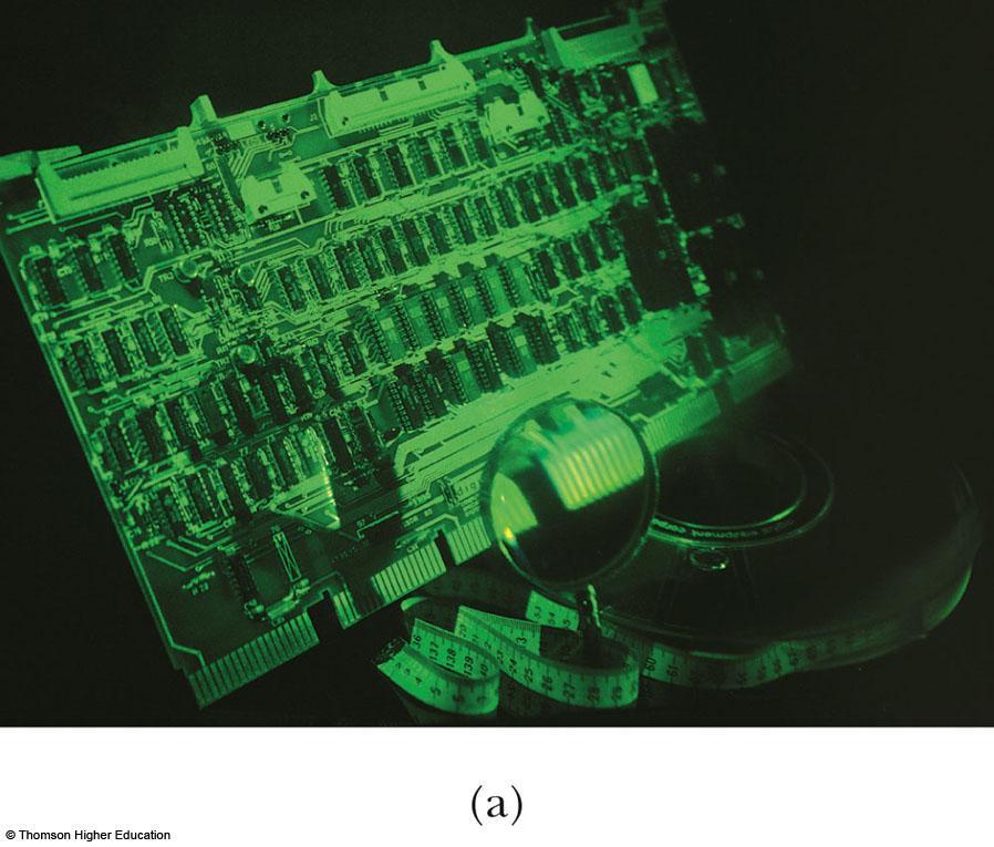
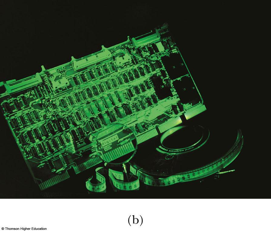
42 Holography, Example
43 Diffraction of X-Rays by Crystals X-rays are electromagnetic waves of very short wavelength Max von Laue suggested that the regular array of atoms in a crystal could act as a three-dimensional diffraction grating for x- rays

44 Diffraction of X-Rays by Crystals, Set-Up A collimated beam of monochromatic x-rays is incident on a crystal The diffracted beams are very intense in certain directions This corresponds to constructive interference from waves reflected from layers of atoms in the crystal The diffracted beams form an array of spots known as a Laue pattern

45 Laue Pattern for Beryl

46 Laue Pattern for Rubisco
47 X-Ray Diffraction, Equations This is a two-dimensional description of the reflection of the x-ray beams The condition for constructive interference is 2d sin θ = mλ where m = 1, 2, 3 This condition is known as Bragg s law This can also be used to calculate the spacing between atomic planes

48 Polarization of Light Waves The direction of polarization of each individual wave is defined to be the direction in which the electric field is vibrating In this example, the direction of polarization is along the y-axis
49 Unpolarized Light, Example All directions of vibration from a wave source are possible The resultant em wave is a superposition of waves vibrating in many different directions This is an unpolarized wave The arrows show a few possible directions of the waves in the beam
50 Polarization of Light, cont. A wave is said to be linearly polarized if the resultant electric field vibrates in the same direction at all times at a particular point The plane formed by E and the direction of propagation is called the plane of polarization of the wave
51 Methods of Polarization It is possible to obtain a linearly polarized beam from an unpolarized beam by removing all waves from the beam except those whose electric field vectors oscillate in a single plane Processes for accomplishing this include Selective absorption Reflection Double refraction Scattering
52 Polarization by Selective Absorption The most common technique for polarizing light Uses a material that transmits waves whose electric field vectors lie in the plane parallel to a certain direction and absorbs waves whose electric field vectors are in all other directions
53 Selective Absorption, cont. E. H. Land discovered a material that polarizes light through selective absorption He called the material Polaroid The molecules readily absorb light whose electric field vector is parallel to their lengths and allow light through whose electric field vector is perpendicular to their lengths
54 Selective Absorption, final It is common to refer to the direction perpendicular to the molecular chains as the transmission axis In an ideal polarizer, All light with the electric field parallel to the transmission axis is transmitted All light with the electric field perpendicular to the transmission axis is absorbed
55 Active Figure Use the active figure to rotate the analyzer Observe the effect on the transmitted light PLAY ACTIVE FIGURE
56 Intensity of a Polarized Beam The intensity of the polarized beam transmitted through the second polarizing sheet (the analyzer) varies as I = I max cos 2 θ I max is the intensity of the polarized wave incident on the analyzer This is known as Malus law and applies to any two polarizing materials whose transmission axes are at an angle of θ to each other
57 Intensity of a Polarized Beam, cont. The intensity of the transmitted beam is a maximum when the transmission axes are parallel θ = 0 or 180 o The intensity is zero when the transmission axes are perpendicular to each other This would cause complete absorption

58 Intensity of Polarized Light, Examples On the left, the transmission axes are aligned and maximum intensity occurs In the middle, the axes are at 45 o to each other and less intensity occurs On the right, the transmission axes are perpendicular and the light intensity is a minimum
59 Polarization by Reflection When an unpolarized light beam is reflected from a surface, the reflected light may be Completely polarized Partially polarized Unpolarized It depends on the angle of incidence If the angle is 0, the reflected beam is unpolarized For other angles, there is some degree of polarization For one particular angle, the beam is completely polarized
60 Polarization by Reflection, cont. The angle of incidence for which the reflected beam is completely polarized is called the polarizing angle, θ p Brewster s law relates the polarizing angle to the index of refraction for the material tan θp n n θ p may also be called Brewster s angle 2 1

61 Polarization by Reflection, Partially Polarized Example Unpolarized light is incident on a reflecting surface The reflected beam is partially polarized The refracted beam is partially polarized

62 Polarization by Reflection, Completely Polarized Example Unpolarized light is incident on a reflecting surface The reflected beam is completely polarized The refracted beam is perpendicular to the reflected beam The angle of incidence is Brewster s angle
63 Polarization by Double Refraction In certain crystalline structures, the speed of light is not the same in all directions Such materials are characterized by two indices of refraction They are often called double-refracting or birefringent materials

64 Polarization by Double Refraction, cont. Unpolarized light splits into two plane-polarized rays The two rays are in mutual perpendicular directions Indicated by the dots and arrows
65 Polarization by Double Refraction, Rays The ordinary (O) ray is characterized by an index of refraction of n o This is the same in all directions The second ray is the extraordinary (E) ray which travels at different speeds in different directions Characterized by an index of refraction of n E that varies with the direction of propagation

66 Polarization by Double Refraction, Optic Axis There is one direction, called the optic axis, along which the ordinary and extraordinary rays have the same speed n O = n E The difference in speeds for the two rays is a maximum in the direction perpendicular to the optic axis
67 Some Indices of Refraction

68 Optical Stress Analysis Some materials become birefringent when stressed When a material is stressed, a series of light and dark bands is observed The light bands correspond to areas of greatest stress Optical stress analysis uses plastic models to test for regions of potential weaknesses
69 Polarization by Scattering When light is incident on any material, the electrons in the material can absorb and reradiate part of the light This process is called scattering An example of scattering is the sunlight reaching an observer on the Earth being partially polarized
70 Polarization by Scattering, cont. The horizontal part of the electric field vector in the incident wave causes the charges to vibrate horizontally The vertical part of the vector simultaneously causes them to vibrate vertically If the observer looks straight up, he sees light that is completely polarized in the horizontal direction
71 Scattering, cont. Short wavelengths (violet) are scattered more efficiently than long wavelengths (red) When sunlight is scattered by gas molecules in the air, the violet is scattered more intensely than the red When you look up, you see blue Your eyes are more sensitive to blue, so you see blue instead of violet At sunrise or sunset, much of the blue is scattered away, leaving the light at the red end of the spectrum
72 Optical Activity Certain materials display the property of optical activity A material is said to be optically active if it rotates the plane of polarization of any light transmitted through it Molecular asymmetry determines whether a material is optically active
Chapter 36. Diffraction. Dr. Armen Kocharian
 Chapter 36 Diffraction Dr. Armen Kocharian Diffraction Light of wavelength comparable to or larger than the width of a slit spreads out in all forward directions upon passing through the slit This phenomena
Diffraction. Single-slit diffraction. Diffraction by a circular aperture. Chapter 38. In the forward direction, the intensity is maximal.
 Diffraction Chapter 38 Huygens construction may be used to find the wave observed on the downstream side of an aperture of any shape. Diffraction The interference pattern encodes the shape as a Fourier
Chapter 24. Wave Optics
 Chapter 24 Wave Optics Diffraction Huygen s principle requires that the waves spread out after they pass through slits This spreading out of light from its initial line of travel is called diffraction
Chapter 33 cont. The Nature of Light and Propagation of Light (lecture 2) Dr. Armen Kocharian
 Dr. Armen Kocharian") Chapter 33 cont The Nature of Light and Propagation of Light (lecture 2) Dr. Armen Kocharian Polarization of Light Waves The direction of polarization of each individual wave is defined to be the direction
Chapter 33 cont The Nature of Light and Propagation of Light (lecture 2) Dr. Armen Kocharian Polarization of Light Waves The direction of polarization of each individual wave is defined to be the direction
Chapter 24. Wave Optics
 Chapter 24 Wave Optics Wave Optics The wave nature of light is needed to explain various phenomena Interference Diffraction Polarization The particle nature of light was the basis for ray (geometric) optics
The diffraction pattern from a hexagonally-shaped hole. Note the six-fold symmetry of the pattern. Observation of such complex patterns can reveal
 The diffraction pattern from a hexagonally-shaped hole. Note the six-fold symmetry of the pattern. Observation of such complex patterns can reveal the underlying symmetry structure of the object that diffracts
specular diffuse reflection.
 Lesson 8 Light and Optics The Nature of Light Properties of Light: Reflection Refraction Interference Diffraction Polarization Dispersion and Prisms Total Internal Reflection Huygens s Principle The Nature
Chapter 24. Wave Optics. Wave Optics. The wave nature of light is needed to explain various phenomena
 Chapter 24 Wave Optics Wave Optics The wave nature of light is needed to explain various phenomena Interference Diffraction Polarization The particle nature of light was the basis for ray (geometric) optics
Chapter 25. Wave Optics
 Chapter 25 Wave Optics Interference Light waves interfere with each other much like mechanical waves do All interference associated with light waves arises when the electromagnetic fields that constitute
Lecture 4. Physics 1502: Lecture 35 Today s Agenda. Homework 09: Wednesday December 9
 Physics 1502: Lecture 35 Today s Agenda Announcements: Midterm 2: graded soon» solutions Homework 09: Wednesday December 9 Optics Diffraction» Introduction to diffraction» Diffraction from narrow slits»
PHYS:1200 LECTURE 32 LIGHT AND OPTICS (4)
") 1 PHYS:1200 LECTURE 32 LIGHT AND OPTICS (4) The first three lectures in this unit dealt with what is for called geometric optics. Geometric optics, treats light as a collection of rays that travel in straight
1 PHYS:1200 LECTURE 32 LIGHT AND OPTICS (4) The first three lectures in this unit dealt with what is for called geometric optics. Geometric optics, treats light as a collection of rays that travel in straight
CHAPTER 26 INTERFERENCE AND DIFFRACTION
 CHAPTER 26 INTERFERENCE AND DIFFRACTION INTERFERENCE CONSTRUCTIVE DESTRUCTIVE YOUNG S EXPERIMENT THIN FILMS NEWTON S RINGS DIFFRACTION SINGLE SLIT MULTIPLE SLITS RESOLVING POWER 1 IN PHASE 180 0 OUT OF
Chapter 36. Diffraction. Copyright 2014 John Wiley & Sons, Inc. All rights reserved.
 Chapter 36 Diffraction Copyright 36-1 Single-Slit Diffraction Learning Objectives 36.01 Describe the diffraction of light waves by a narrow opening and an edge, and also describe the resulting interference
Michelson Interferometer
 Michelson Interferometer The Michelson interferometer uses the interference of two reflected waves The third, beamsplitting, mirror is partially reflecting ( half silvered, except it s a thin Aluminum
Electromagnetic waves
 Electromagnetic waves Now we re back to thinking of light as specifically being an electromagnetic wave u u u oscillating electric and magnetic fields perpendicular to each other propagating through space
Lecture 16 Diffraction Ch. 36
 Lecture 16 Diffraction Ch. 36 Topics Newtons Rings Diffraction and the wave theory Single slit diffraction Intensity of single slit diffraction Double slit diffraction Diffraction grating Dispersion and
Experiment 8 Wave Optics
 Physics 263 Experiment 8 Wave Optics In this laboratory, we will perform two experiments on wave optics. 1 Double Slit Interference In two-slit interference, light falls on an opaque screen with two closely
Electricity & Optics
 Physics 24100 Electricity & Optics Lecture 27 Chapter 33 sec. 7-8 Fall 2017 Semester Professor Koltick Clicker Question Bright light of wavelength 585 nm is incident perpendicularly on a soap film (n =
PHYSICS. Chapter 33 Lecture FOR SCIENTISTS AND ENGINEERS A STRATEGIC APPROACH 4/E RANDALL D. KNIGHT
 PHYSICS FOR SCIENTISTS AND ENGINEERS A STRATEGIC APPROACH 4/E Chapter 33 Lecture RANDALL D. KNIGHT Chapter 33 Wave Optics IN THIS CHAPTER, you will learn about and apply the wave model of light. Slide
OPTICS MIRRORS AND LENSES
 Downloaded from OPTICS MIRRORS AND LENSES 1. An object AB is kept in front of a concave mirror as shown in the figure. (i)complete the ray diagram showing the image formation of the object. (ii) How will
The sources must be coherent. This means they emit waves with a constant phase with respect to each other.
 CH. 24 Wave Optics The sources must be coherent. This means they emit waves with a constant phase with respect to each other. The waves need to have identical wavelengths. Can t be coherent without this.
Chapter 38 Wave Optics (II)
") Chapter 38 Wave Optics (II) Initiation: Young s ideas on light were daring and imaginative, but he did not provide rigorous mathematical theory and, more importantly, he is arrogant. Progress: Fresnel,
Chapter 38 Wave Optics (II) Initiation: Young s ideas on light were daring and imaginative, but he did not provide rigorous mathematical theory and, more importantly, he is arrogant. Progress: Fresnel,
Chapter 8: Physical Optics
 Chapter 8: Physical Optics Whether light is a particle or a wave had puzzled physicists for centuries. In this chapter, we only analyze light as a wave using basic optical concepts such as interference
UNIT 102-9: INTERFERENCE AND DIFFRACTION
 Name St.No. - Date(YY/MM/DD) / / Section Group # UNIT 102-9: INTERFERENCE AND DIFFRACTION Patterns created by interference of light in a thin film. OBJECTIVES 1. Understand the creation of double-slit
Physics 1CL WAVE OPTICS: INTERFERENCE AND DIFFRACTION Fall 2009
 Introduction An important property of waves is interference. You are familiar with some simple examples of interference of sound waves. This interference effect produces positions having large amplitude
Physics 214 Midterm Fall 2003 Form A
 1. A ray of light is incident at the center of the flat circular surface of a hemispherical glass object as shown in the figure. The refracted ray A. emerges from the glass bent at an angle θ 2 with respect
Wave Optics. April 9, 2014 Chapter 34 1
 Wave Optics April 9, 2014 Chapter 34 1 Announcements! Remainder of this week: Wave Optics! Next week: Last of biweekly exams, then relativity! Last week: Review of entire course, no exam! Final exam Wednesday,
Chapter 15. Light Waves
 Chapter 15 Light Waves Chapter 15 is finished, but is not in camera-ready format. All diagrams are missing, but here are some excerpts from the text with omissions indicated by... After 15.1, read 15.2
L 32 Light and Optics [3]
![L 32 Light and Optics [3]](/thumbs/78/77867745.jpg "L 32 Light and Optics [3]") L 32 Light and Optics [3] Measurements of the speed of light The bending of light refraction Total internal reflection Dispersion Dispersion Rainbows Atmospheric scattering Blue sky red sunsets Light and
L 32 Light and Optics [3] Measurements of the speed of light The bending of light refraction Total internal reflection Dispersion Dispersion Rainbows Atmospheric scattering Blue sky red sunsets Light and
Intermediate Physics PHYS102
 Intermediate Physics PHYS102 Dr Richard H. Cyburt Assistant Professor of Physics My office: 402c in the Science Building My phone: (304) 384-6006 My email: rcyburt@concord.edu My webpage: www.concord.edu/rcyburt
PY212 Lecture 25. Prof. Tulika Bose 12/3/09. Interference and Diffraction. Fun Link: Diffraction with Ace Ventura
 PY212 Lecture 25 Interference and Diffraction Prof. Tulika Bose 12/3/09 Fun Link: Diffraction with Ace Ventura Summary from last time The wave theory of light is strengthened by the interference and diffraction
Chapter 24 - The Wave Nature of Light
 Chapter 24 - The Wave Nature of Light Summary Four Consequences of the Wave nature of Light: Diffraction Dispersion Interference Polarization Huygens principle: every point on a wavefront is a source of
Physics 202 Homework 9
 Physics 202 Homework 9 May 29, 2013 1. A sheet that is made of plastic (n = 1.60) covers one slit of a double slit 488 nm (see Figure 1). When the double slit is illuminated by monochromatic light (wavelength
Basic Optics : Microlithography Optics Part 4: Polarization
 Electromagnetic Radiation Polarization: Linear, Circular, Elliptical Ordinary and extraordinary rays Polarization by reflection: Brewster angle Polarization by Dichroism Double refraction (Birefringence)
Diffraction at a single slit and double slit Measurement of the diameter of a hair
 Diffraction at a single slit and double slit Measurement of the diameter of a hair AREEJ AL JARB Background... 3 Objects of the experiments 4 Principles Single slit... 4 Double slit.. 6 Setup. 7 Procedure
f. (5.3.1) So, the higher frequency means the lower wavelength. Visible part of light spectrum covers the range of wavelengths from
 So, the higher frequency means the lower wavelength. Visible part of light spectrum covers the range of wavelengths from") Lecture 5-3 Interference and Diffraction of EM Waves During our previous lectures we have been talking about electromagnetic (EM) waves. As we know, harmonic waves of any type represent periodic process
Lecture 5-3 Interference and Diffraction of EM Waves During our previous lectures we have been talking about electromagnetic (EM) waves. As we know, harmonic waves of any type represent periodic process
25-1 Interference from Two Sources
 25-1 Interference from Two Sources In this chapter, our focus will be on the wave behavior of light, and on how two or more light waves interfere. However, the same concepts apply to sound waves, and other
To see how a sharp edge or an aperture affect light. To analyze single-slit diffraction and calculate the intensity of the light
 Diffraction Goals for lecture To see how a sharp edge or an aperture affect light To analyze single-slit diffraction and calculate the intensity of the light To investigate the effect on light of many
Lecture 4 Recap of PHYS110-1 lecture Physical Optics - 4 lectures EM spectrum and colour Light sources Interference and diffraction Polarization
 Lecture 4 Recap of PHYS110-1 lecture Physical Optics - 4 lectures EM spectrum and colour Light sources Interference and diffraction Polarization Lens Aberrations - 3 lectures Spherical aberrations Coma,
Models of Light The wave model: The ray model: The photon model:
 Models of Light The wave model: under many circumstances, light exhibits the same behavior as sound or water waves. The study of light as a wave is called wave optics. The ray model: The properties of
ConcepTest PowerPoints
 ConcepTest PowerPoints Chapter 24 Physics: Principles with Applications, 6 th edition Giancoli 2005 Pearson Prentice Hall This work is protected by United States copyright laws and is provided solely for
PHY 222 Lab 11 Interference and Diffraction Patterns Investigating interference and diffraction of light waves
 PHY 222 Lab 11 Interference and Diffraction Patterns Investigating interference and diffraction of light waves Print Your Name Print Your Partners' Names Instructions April 17, 2015 Before lab, read the
Physical Optics. You can observe a lot just by watching. Yogi Berra ( )
") Physical Optics You can observe a lot just by watching. Yogi Berra (1925-2015) OBJECTIVES To observe some interference and diffraction phenomena with visible light. THEORY In a previous experiment you
Physical Optics You can observe a lot just by watching. Yogi Berra (1925-2015) OBJECTIVES To observe some interference and diffraction phenomena with visible light. THEORY In a previous experiment you
Chapter 37. Wave Optics
 Chapter 37 Wave Optics Wave Optics Wave optics is a study concerned with phenomena that cannot be adequately explained by geometric (ray) optics. Sometimes called physical optics These phenomena include:
Diffraction and Interference of Plane Light Waves
 1 Diffraction and Interference of Plane Light Waves Introduction In this experiment you will become familiar with diffraction patterns created when a beam of light scatters from objects placed in its path.
Experiment 5: Polarization and Interference
 Experiment 5: Polarization and Interference Nate Saffold nas2173@columbia.edu Office Hour: Mondays, 5:30PM-6:30PM @ Pupin 1216 INTRO TO EXPERIMENTAL PHYS-LAB 1493/1494/2699 Introduction Outline: Review
Chapter 24 The Wave Nature of Light
 Chapter 24 The Wave Nature of Light 24.1 Waves Versus Particles; Huygens Principle and Diffraction Huygens principle: Every point on a wave front acts as a point source; the wavefront as it develops is
Chapter 36 Diffraction
 Chapter 36 Diffraction In Chapter 35, we saw how light beams passing through different slits can interfere with each other and how a beam after passing through a single slit flares diffracts in Young's
Textbook Reference: Physics (Wilson, Buffa, Lou): Chapter 24
: Chapter 24") AP Physics-B Physical Optics Introduction: We have seen that the reflection and refraction of light can be understood in terms of both rays and wave fronts of light. Light rays are quite compatible with
AP Physics-B Physical Optics Introduction: We have seen that the reflection and refraction of light can be understood in terms of both rays and wave fronts of light. Light rays are quite compatible with
Lecture Wave Optics. Physics Help Q&A: tutor.leiacademy.org
 Lecture 1202 Wave Optics Physics Help Q&A: tutor.leiacademy.org Total Internal Reflection A phenomenon called total internal reflectioncan occur when light is directed from a medium having a given index
Chapter 82 Example and Supplementary Problems
 Chapter 82 Example and Supplementary Problems Nature of Polarized Light: 1) A partially polarized beam is composed of 2.5W/m 2 of polarized and 4.0W/m 2 of unpolarized light. Determine the degree of polarization
Polarisation and Diffraction
 2015 EdExcel A Level Physics 2015 EdExcel A Level Physics Topic Topic 5 5 Polarisation and Diffraction Polarization Polarization is a characteristic of all transverse waves. Oscillation which take places
Dr. Quantum. General Physics 2 Light as a Wave 1
 Dr. Quantum General Physics 2 Light as a Wave 1 The Nature of Light When studying geometric optics, we used a ray model to describe the behavior of light. A wave model of light is necessary to describe
Interference & Diffraction
 Electromagnetism & Light Interference & Diffraction https://youtu.be/iuv6hy6zsd0?t=2m17s Your opinion is very important to us. What study material would you recommend for future classes of Phys140/141?
Optics Vac Work MT 2008
 Optics Vac Work MT 2008 1. Explain what is meant by the Fraunhofer condition for diffraction. [4] An aperture lies in the plane z = 0 and has amplitude transmission function T(y) independent of x. It is
PH 222-3A Fall Diffraction Lectures Chapter 36 (Halliday/Resnick/Walker, Fundamentals of Physics 8 th edition)
") PH 222-3A Fall 2012 Diffraction Lectures 28-29 Chapter 36 (Halliday/Resnick/Walker, Fundamentals of Physics 8 th edition) 1 Chapter 36 Diffraction In Chapter 35, we saw how light beams passing through
PH 222-3A Fall 2012 Diffraction Lectures 28-29 Chapter 36 (Halliday/Resnick/Walker, Fundamentals of Physics 8 th edition) 1 Chapter 36 Diffraction In Chapter 35, we saw how light beams passing through
EM Waves Practice Problems
 PSI AP Physics 2 Name 1. Sir Isaac Newton was one of the first physicists to study light. What properties of light did he explain by using the particle model? 2. Who was the first person who was credited
PHY132 Introduction to Physics II Class 5 Outline:
 PHY132 Introduction to Physics II Class 5 Outline: Ch. 22, sections 22.1-22.4 (Note we are skipping sections 22.5 and 22.6 in this course) Light and Optics Double-Slit Interference The Diffraction Grating
Physics 1C, Summer 2011 (Session 1) Practice Midterm 2 (50+4 points) Solutions
 Practice Midterm 2 (50+4 points) Solutions") Physics 1C, Summer 2011 (Session 1) Practice Midterm 2 (50+4 points) s Problem 1 (5x2 = 10 points) Label the following statements as True or False, with a one- or two-sentence explanation for why you chose
Physics 1C, Summer 2011 (Session 1) Practice Midterm 2 (50+4 points) s Problem 1 (5x2 = 10 points) Label the following statements as True or False, with a one- or two-sentence explanation for why you chose
Chapter 35 &36 Physical Optics
 Chapter 35 &36 Physical Optics Physical Optics Phase Difference & Coherence Thin Film Interference 2-Slit Interference Single Slit Interference Diffraction Patterns Diffraction Grating Diffraction & Resolution
PHYSICS 1040L LAB LAB 7: DIFFRACTION & INTERFERENCE
 PHYSICS 1040L LAB LAB 7: DIFFRACTION & INTERFERENCE Object: To investigate the diffraction and interference of light, Apparatus: Lasers, optical bench, single and double slits. screen and mounts. Theory:
Lecture 39. Chapter 37 Diffraction
 Lecture 39 Chapter 37 Diffraction Interference Review Combining waves from small number of coherent sources double-slit experiment with slit width much smaller than wavelength of the light Diffraction
Chapter 37. Interference of Light Waves
 Chapter 37 Interference of Light Waves Wave Optics Wave optics is a study concerned with phenomena that cannot be adequately explained by geometric (ray) optics These phenomena include: Interference Diffraction
DIFFRACTION 4.1 DIFFRACTION Difference between Interference and Diffraction Classification Of Diffraction Phenomena
 4.1 DIFFRACTION Suppose a light wave incident on a slit AB of sufficient width b, as shown in Figure 1. According to concept of rectilinear propagation of light the region A B on the screen should be uniformly
Lab 5: Diffraction and Interference
 Lab 5: Diffraction and Interference Light is a wave, an electromagnetic wave, and under the proper circumstances, it exhibits wave phenomena, such as constructive and destructive interference. The wavelength
Final Exam and End Material Test Friday, May 12, 10:00-12:00
 Final Exam and End Material Test Friday, May 12, 10:00-12:00 Test rooms: Instructor Sections Room Dr. Hale F, H 104 Physics Dr. Kurter B, N 125 BCH Dr. Madison K, M B-10 Bertelsmeyer Dr. Parris J St. Pats
Human Retina. Sharp Spot: Fovea Blind Spot: Optic Nerve
 I am Watching YOU!! Human Retina Sharp Spot: Fovea Blind Spot: Optic Nerve Human Vision An optical Tuning Fork Optical Antennae: Rods & Cones Rods: Intensity Cones: Color Where does light actually come
Wave Phenomena Physics 15c. Lecture 19 Diffraction
 Wave Phenomena Physics 15c Lecture 19 Diffraction What We Did Last Time Studied interference > waves overlap Amplitudes add up Intensity = (amplitude) does not add up Thin-film interference Reflectivity
INTERFERENCE. where, m = 0, 1, 2,... (1.2) otherwise, if it is half integral multiple of wavelength, the interference would be destructive.
 otherwise, if it is half integral multiple of wavelength, the interference would be destructive.") 1.1 INTERFERENCE When two (or more than two) waves of the same frequency travel almost in the same direction and have a phase difference that remains constant with time, the resultant intensity of light
1.1 INTERFERENCE When two (or more than two) waves of the same frequency travel almost in the same direction and have a phase difference that remains constant with time, the resultant intensity of light
Interference of Light
 Interference of Light Review: Principle of Superposition When two or more waves interact they interfere. Wave interference is governed by the principle of superposition. The superposition principle says
Interference. Electric fields from two different sources at a single location add together. The same is true for magnetic fields at a single location.
 Interference Electric fields from two different sources at a single location add together. The same is true for magnetic fields at a single location. Thus, interacting electromagnetic waves also add together.
Diffraction Diffraction occurs when light waves pass through an aperture Huygen's Principal: each point on wavefront acts as source of another wave
 Diffraction Diffraction occurs when light waves pass through an aperture Huygen's Principal: each point on wavefront acts as source of another wave If light coming from infinity point source at infinity
Diffraction. Introduction: Diffraction is bending of waves around an obstacle (barrier) or spreading of waves passing through a narrow slit.
 or spreading of waves passing through a narrow slit.") Introduction: Diffraction is bending of waves around an obstacle (barrier) or spreading of waves passing through a narrow slit. Diffraction amount depends on λ/a proportion If a >> λ diffraction is negligible
Introduction: Diffraction is bending of waves around an obstacle (barrier) or spreading of waves passing through a narrow slit. Diffraction amount depends on λ/a proportion If a >> λ diffraction is negligible
Review Session 1. Dr. Flera Rizatdinova
 Review Session 1 Dr. Flera Rizatdinova Summary of Chapter 23 Index of refraction: Angle of reflection equals angle of incidence Plane mirror: image is virtual, upright, and the same size as the object
Chapter 2: Wave Optics
 Chapter : Wave Optics P-1. We can write a plane wave with the z axis taken in the direction of the wave vector k as u(,) r t Acos tkzarg( A) As c /, T 1/ and k / we can rewrite the plane wave as t z u(,)
Interference and Diffraction of Light
 Name Date Time to Complete h m Partner Course/ Section / Grade Interference and Diffraction of Light Reflection by mirrors and refraction by prisms and lenses can be analyzed using the simple ray model
Chapter 4 - Diffraction
 Diffraction is the phenomenon that occurs when a wave interacts with an obstacle. David J. Starling Penn State Hazleton PHYS 214 When a wave interacts with an obstacle, the waves spread out and interfere.
Wave Optics. April 11, 2014 Chapter 34 1
 Wave Optics April 11, 2014 Chapter 34 1 Announcements! Exam tomorrow! We/Thu: Relativity! Last week: Review of entire course, no exam! Final exam Wednesday, April 30, 8-10 PM Location: WH B115 (Wells Hall)
Single slit diffraction
 Single slit diffraction Book page 364-367 Review double slit Core Assume paths of the two rays are parallel This is a good assumption if D >>> d PD = R 2 R 1 = dsin θ since sin θ = PD d Constructive interference
Electromagnetism & Light. Interference & Diffraction
 Electromagnetism & Light Interference & Diffraction Your opinion is very important to us. What study material would you recommend for future classes of Phys140/141? A. SmartPhysics alone B. SmartPhysics
Polarization. Bởi: OpenStaxCollege
 Polarization Bởi: OpenStaxCollege Polaroid sunglasses are familiar to most of us. They have a special ability to cut the glare of light reflected from water or glass (see [link]). Polaroids have this ability
Physical optics. Introduction. University of Ottawa Department of Physics
 Physical optics Introduction The true nature of light has been, and continues to be, an alluring subject in physics. While predictions of light behaviour can be made with great success and precision, the
Activity 9.1 The Diffraction Grating
 PHY385H1F Introductory Optics Practicals Day 9 Diffraction November 29, 2010 Please work in a team of 3 or 4 students. All members should find a way to contribute. Two members have a particular role, and
UNIT VI OPTICS ALL THE POSSIBLE FORMULAE
 58 UNIT VI OPTICS ALL THE POSSIBLE FORMULAE Relation between focal length and radius of curvature of a mirror/lens, f = R/2 Mirror formula: Magnification produced by a mirror: m = - = - Snell s law: 1
10.5 Polarization of Light
 10.5 Polarization of Light Electromagnetic waves have electric and magnetic fields that are perpendicular to each other and to the direction of propagation. These fields can take many different directions
Unit 5.C Physical Optics Essential Fundamentals of Physical Optics
 Unit 5.C Physical Optics Essential Fundamentals of Physical Optics Early Booklet E.C.: + 1 Unit 5.C Hwk. Pts.: / 25 Unit 5.C Lab Pts.: / 20 Late, Incomplete, No Work, No Units Fees? Y / N 1. Light reflects
Ray Optics. Lecture 23. Chapter 23. Physics II. Course website:
 Lecture 23 Chapter 23 Physics II Ray Optics Course website: http://faculty.uml.edu/andriy_danylov/teaching/physicsii Let s finish talking about a diffraction grating Diffraction Grating Let s improve (more
University Physics (Prof. David Flory) Chapt_37 Monday, August 06, 2007
 Chapt_37 Monday, August 06, 2007") Name: Date: 1. If we increase the wavelength of the light used to form a double-slit diffraction pattern: A) the width of the central diffraction peak increases and the number of bright fringes within
Name: Date: 1. If we increase the wavelength of the light used to form a double-slit diffraction pattern: A) the width of the central diffraction peak increases and the number of bright fringes within
Physical or wave optics
 Physical or wave optics In the last chapter, we have been studying geometric optics u light moves in straight lines u can summarize everything by indicating direction of light using a ray u light behaves
Physical Optics. 1 st year physics laboratories. University of Ottawa.
 Physical Optics 1 st year physics laboratories University of Ottawa https://uottawa.brightspace.com/d2l/home INTRODUCTION Physical optics deals with light as a wave which can bend around obstacles (diffraction)
Understanding Fraunhofer Diffraction
 [ Assignment View ] [ Eðlisfræði 2, vor 2007 36. Diffraction Assignment is due at 2:00am on Wednesday, January 17, 2007 Credit for problems submitted late will decrease to 0% after the deadline has passed.
Physics 228 Today: Diffraction, diffraction grating
 Physics 228 Today: Diffraction, diffraction grating Website: Sakai 01:750:228 or www.physics.rutgers.edu/ugrad/228 Diffraction is a further expansion of the idea of interference. We expand from two sources
Polarization of Light
 Polarization of Light Introduction Light, viewed classically, is a transverse electromagnetic wave. Namely, the underlying oscillation (in this case oscillating electric and magnetic fields) is along directions
College Physics 150. Chapter 25 Interference and Diffraction
 College Physics 50 Chapter 5 Interference and Diffraction Constructive and Destructive Interference The Michelson Interferometer Thin Films Young s Double Slit Experiment Gratings Diffraction Resolution
Diffraction and Interference of Plane Light Waves
 PHY 92 Diffraction and Interference of Plane Light Waves Diffraction and Interference of Plane Light Waves Introduction In this experiment you will become familiar with diffraction patterns created when
Optics Wave Behavior in Optics Diffraction
 Optics Wave Behavior in Optics Diffraction Lana Sheridan De Anza College June 15, 2018 Last time Interference of light: the Double-Slit experiment multiple slit interference diffraction gratings Overview
CHAPTER 24 The Wave Nature of Light
 CHAPTER 24 The Wave Nature of Light http://www.physicsclassroom.com/class/light/lighttoc.html Units Waves Versus Particles; Huygens Principle and Diffraction Huygens Principle and the Law of Refraction
light Chapter Type equation here. Important long questions
 Type equation here. Light Chapter 9 Important long questions Q.9.1 Describe Young s double slit experiment for the demonstration of interference of. Derive an expression for fringe spacing? Ans. Young
22.1. Visualize: Please refer to Figure Ex22.1. Solve: (a)
") 22.. Visualize: Please refer to Figure Ex22.. Solve: (a) (b) The initial light pattern is a double-slit interference pattern. It is centered behind the midpoint of the slits. The slight decrease in intensity
22.. Visualize: Please refer to Figure Ex22.. Solve: (a) (b) The initial light pattern is a double-slit interference pattern. It is centered behind the midpoint of the slits. The slight decrease in intensity