Rendering 13 Deferred Shading
|
|
|
- Deborah Francis
- 5 years ago
- Views:
Transcription

1 Catlike Coding Unity C# Tutorials Rendering 13 Deferred Shading Explore deferred shading. Fill Geometry Buffers. Support both HDR and LDR. Work with Deferred Reflections. This is part 13 of a tutorial series about rendering. The previous installment covered semitransparent shadows. Now we'll look at deferred shading. This tutorial was made with Unity 5.5.0f3. The anatomy of geometry.

2 1 Another Rendering Path Up to this point we've always used Unity's forward rendering path. But that's not the only rendering method that Unity supports. There's also the deferred path. And there are also the legacy vertex lit and the legacy deferred paths, but we won't cover those. So there is a deferred rendering path, but why would we bother with it? After all, we can render everything we want using the forward path. To answer that question, let's investigate their differences. 1.1 Switching Paths Which rendering path is used is defined by the project-wide graphics settings. You can get there via Edit / Project Settings / Graphics. The rendering path and a few other settings are configured in three tiers. These tiers correspond to different categories of GPUs. The better the GPU, the higher a tier Unity uses. You can select which tier the editor uses via the Editor / Graphics Emulation submenu. Graphics settings, per tier. To change the rendering path, disable Use Defaults for the desired tier, then select either Forward or Deferred as the Rendering Path. 1.2 Comparing Draw Calls


3 I'll use the Shadows Scene from the Rendering 7, Shadows tutorial to compare both approaches. This scene has its Ambient Intensity set to zero, to make the shadows more visible. Because our own shader doesn't support deferred yet, change the used material so it relies on the standard shader. The scene has quite a few objects and two directional lights. Let's look at it both without and with shadows enabled for both lights. Shadows scene, without and with shadows. While using the forward rendering path, use the frame debugger to examine how the scene gets rendered. There are 66 geometry objects in the scene, all visible. If dynamic batching was possible, these could've been drawn with less than 66 batches. However, that only works with a single directional light. As there is an additional light, dynamic batching is not used. And because there are two directional lights, all geometry gets drawn twice. So that's 132 draw calls, 133 with the skybox.


4 Forward rendering, without shadows. When shadows are enabled, we need more draw calls to generate the cascading shadow maps. Recall how directional shadow maps are created. First, the depth buffer is filled, which requires only 48 draw calls, thanks to some dynamic batching. Then, the cascading shadow maps are created. The first light's shadow map ends up requiring 111 draw calls, while the second one needs 121. These shadow maps are rendered to screen-space buffers, which perform filtering. Then the geometry is drawn, once per light. Doing all this requires 418 draw calls. Forward rendering, with shadows. Now disable the shadows again and switch to the deferred rendering path. The scene still looks the same, except that MSAA has been turned off. How does it get drawn this time? Why doesn't MSAA work in deferred mode? Deferred shading relies on data being stored per fragment, which is done via textures. This is not compatible with MSAA, because that anti-aliasing technique relies on subpixel data. While the triangle edges could still benefit from MSAA, the deferred data remains aliased. You'll have to rely one a post-processing filter for anti-aliasing.


5 Deferred rendering, without shadows. Apparently, a GBuffer gets rendered, which requires 45 draw calls. That's one per object, with some dynamic batching. Then the depth texture gets copied, followed by thee draw calls that do something with reflections. After that, we get to lighting, which requires two draw calls, one per light. Then there's a final pass and the skybox, for a total of 55 draw calls. 55 is quite a bit less than 133. It looks like deferred only draws each object once in total, not once per light. Besides that and some other work, each light gets its own draw call. What about when shadows are enabled? Deferred rendering, with shadows.
6 We see that both shadow maps get rendered and then filtered in screen space, right before their lights are drawn. Just like in forward mode, this adds 236 draw calls, for a total of 291. As deferred already created a depth texture, we got that for free. Again, 291 is quite a bit less than Splitting the Work Deferred shading appears to be more efficient when rendering more than one light, compared to forward shading. While forward requires one additional additive pass per object per light, deferred doesn't need this. Of course both still have to render the shadow maps, but deferred doesn't have to pay extra for the depth texture that directional shadows need. How does the deferred path get away with this? To render something, the shader has to grab the mesh data, convert it to the correct space, interpolate it, retrieve and derive surface properties, and calculate lighting. Forward shaders have to repeat all of this for every pixel light that illuminates an object. Additive passes are cheaper than the base pass, because the depth buffer has already been primed, and they don't bother with indirect light. But they still have to repeat most of the work that the base pass has already done. Duplicate work. As the geometry's properties are the same every time, why don't we cache them? Have the base pass store them in a buffer. Then additive passes can reuse that data, eliminating duplicate work. We have to store this data per fragment, so we need a buffer that fits the display, just like the depth and the frame buffer.


7 Caching surface properties. Now we have all the geometry data that we require for lighting available in a buffer. The only thing that's missing is the light itself. But that means we no longer need to render the geometry at all. We can suffice with rendering the light. Furthermore, the base pass only has to fill the buffer. All direct lighting calculations can be deferred until the lights are rendered individually. Hence, deferred shading. Deferred shading.


8 1.4 Many Lights If you're only using a single light, then deferred by itself doesn't provide any benefit. But when using many lights, it shines. Each additional light only adds a little extra work, as long as they don't cast shadows. Also, when geometry and lights are rendered separately, there is no limit to how many lights can affect an object. All lights are pixel lights and illuminate everything in their range. The Pixel Light Count quality setting does not apply. Ten spotlights, deferred succeeds while forward fails. 1.5 Rendering Lights So how are lights themselves rendered? As directional lights affect everything, they are rendered with a single quad that covers the entire view.

9 Directional lights use a quad. This quad is rendered with the Internal-DeferredShading shader. Its fragment program fetches the geometry data from the buffer and relies on the UnityDeferredLibrary include file to configure the light. Then it computes the lighting, just like a forward shader does. Spotlights work the same way, except that they don't have to cover the entire view. Instead, a pyramid is rendered that fits the volume that the spotlight illuminates. So only the visible potion of this volume will be rendered. If it ends up completely hidden behind other geometry, no shading is performed for this light. Spotlights use a pyramid. If a fragment of this pyramid is rendered, it will perform lighting calculations. But this only makes sense if there actually is geometry inside the light's volume. Geometry behind the volume need not be rendered, because the light doesn't reach there. To prevent rendering these unnecessary fragments, the pyramid is first rendered with the Internal-StencilWrite shader. This pass writes to the stencil buffer, which can be used to mask which fragments get rendered later. The only case when this technique can't be used is when the light volume intersects the camera's near plane. Point lights use the same approach, except with an icosphere instead of a pyramid.


10 Point lights use an icosphere. 1.6 Light Range If you've been stepping through the frame debugger, you might have noticed that the colors look weird during the deferred lighting phase. It's as if they're inverted, like a photo negative. The final deferred pass converts this intermediate state to the final correct colors. Inverted colors. Unity does this when the scene is rendered with low dynamic range LDR colors, which is the default. In this case, the colors are written to an ARGB32 texture. Unity logarithmically encodes the colors to achieve a greater dynamic range than usual for this format. The final deferred pass converts to normal colors. When the scene is rendered in high dynamic range HDR Unity uses the ARGBHalf format. In this case, the special encoding is not needed and there is no final deferred pass. Whether HDR is enabled is a property of the camera. Switch it on, so we see normal colors when using the frame debugger.

11 HDR enabled.


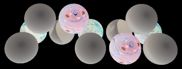
12 1.7 Geometry Buffers The downside of caching data is that it has to be stored somewhere. The deferred rendering path uses multiple render textures for this purpose. These textures are known as geometry buffers, or G-buffers for short. Deferred shading requires four G-buffers. Their combined size is 160 bits per pixel for LDR and 192 bits per pixel for HDR. That's quite a bit more than a single 32-bit frame buffer. Modern desktop GPUs can deal with that, but mobile and even laptop GPUs can have trouble with higher resolutions. You can inspect some of the data in the G-buffer via the scene window. Use the button at the top left of the window to select a different display mode. It's set to Shaded by default. When using the deferred rendering path, you can choose one of the four Deferred options. For example, Normal shows the RGB channels of the buffer that contains the surface normals. Standard spheres and their deferred normals. You can also inspects the multiple render targets of a draw call via the frame debugger. There is a dropdown menu to select the render target at the top left of the menu on the right side of the window. The default is the first target, which is RT 0. Selecting a render target. 1.8 Mixing Rendering Modes
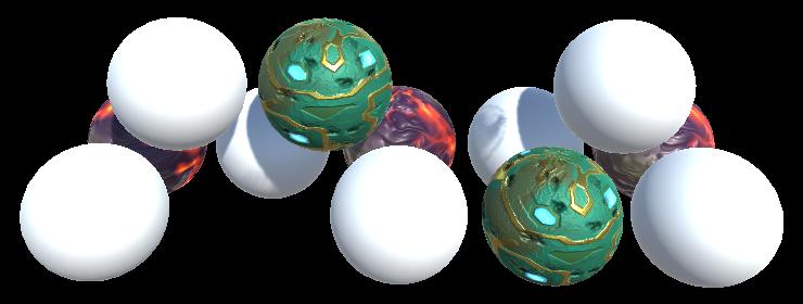
13 Our own shader doesn't support the deferred rendering path yet. So what would happen if some of the objects in the scene were rendered with our shader, while in deferred mode? Mixed spheres, with their deferred normals. Our objects appear to render fine. It turns out that deferred rendering is done first, followed by an additional forward rendering phase. During the deferred rendering phase, the forward objects do not exist. The only exception is when there are directional shadows. In that case, a depth pass is needed for the forward objects. This is done directly after the G-buffers are filled. As a side effect, the forward objects end up as solid black in the albedo buffer.


14 Both deferred and forward rendering. This is true for transparent objects as well. They require a separate forward rendering phase, as usual. Deferred an forward opaque, plus transparent.

15 2 Filling the G-Buffers Now that we have an idea of how deferred shading works, let's add support for it to My First Lighting Shader. This is done by adding a pass with its LightMode tag set to Deferred. The order of the passes doesn't matter. I put it in between the additive and the shadow passes. Pass { Tags { "LightMode" = "Deferred" } } White normals. Unity detects that our shader has a deferred pass, so it includes the opaque and cutout objects that use our shader in the deferred phase. Transparent objects will still be rendered in the transparent phase, of course. Because our pass is empty, everything gets rendered as solid white. We have to add shader features and programs. The deferred pass is mostly the same as the base pass, so copy the contents of that pass, then make a few changes. First, we'll define DEFERRED_PASS instead of FORWARD_BASE_PASS. Second, the deferred pass doesn't need variants for the _RENDERING_FADE and _RENDERING_TRANSPARENT keywords. Third, deferred shading is only possible when the GPU supports writing to multiple render targets. So we'll add a directive to exclude it when those are not supported. I marked these differences.
16 Pass { Tags { "LightMode" = "Deferred" } CGPROGRAM #pragma target 3.0 #pragma exclude_renderers nomrt #pragma shader_feature RENDERING_CUTOUT #pragma shader_feature _METALLIC_MAP #pragma shader_feature SMOOTHNESS_ALBEDO _SMOOTHNESS_METALLIC #pragma shader_feature _NORMAL_MAP #pragma shader_feature _OCCLUSION_MAP #pragma shader_feature _EMISSION_MAP #pragma shader_feature _DETAIL_MASK #pragma shader_feature _DETAIL_ALBEDO_MAP #pragma shader_feature _DETAIL_NORMAL_MAP #pragma vertex MyVertexProgram #pragma fragment MyFragmentProgram #define DEFERRED_PASS #include "My Lighting.cginc" } ENDCG Shaded normals. Now the deferred pass functions roughly like the base pass. So it ends up writing shaded results to the G-buffers, instead of geometry data. This is not correct. We have to output the geometry data and not compute direct lighting.
17 2.1 Four Outputs In My Lighting, we have to support two kinds of output for MyFragmentProgram. In the case of the deferred pass, there are four buffers that we need to fill. We do that by outputting to four targets. In all other cases, we can suffice with a single target. Let's define an output structure for this, directly above MyFragmentProgram. struct FragmentOutput { #if defined(deferred_pass) float4 gbuffer0 : SV_Target0; float4 gbuffer1 : SV_Target1; float4 gbuffer2 : SV_Target2; float4 gbuffer3 : SV_Target3; #else float4 color : SV_Target; #endif }; Shouldn't it be SV_TARGET? You can mix uppercase and lowercase for the target semantics, Unity understands them all. Here I'm using the same format that Unity's most recent shaders use. Note that this isn't true for all semantics. For example, vertex data semantics must all be uppercase. Adjust MyFragmentProgram so it returns this structure. For the deferred pass, we'll have to assign values to all four outputs, which we'll do shortly. The other passes simply copy the final shaded color. FragmentOutput MyFragmentProgram (Interpolators i) { } FragmentOutput output; #if defined(deferred_pass) #else output.color = color; #endif return output;

18 2.2 Buffer 0 The first G-buffer is used to store the diffuse albedo and the surface occlusion. It's an ARGB32 texture, like a regular frame buffer. Albedo is stored in the RGB channels and the occlusion is stored in the A channel. We know the albedo color at this point, and we can use GetOcclusion to access the occlusion value. #if defined(deferred_pass) output.gbuffer0.rgb = albedo; output.gbuffer0.a = GetOcclusion(i); #else Albedo and occlusion. You can use the scene view or the frame debugger to inspect the contents of the first G-buffer, to verify that we fill it correctly. This will show you its RGB channels. However, the A channel isn't shown. To inspect the occlusion data, you can temporarily assign it to the RGB channels.
19 2.3 Buffer 1 The second G-buffer is used to store the specular color in the RGB channels, and the smoothness value in the A channel. It is also an ARGB32 texture. We know what the specular tint is, and can use GetSmoothness to retrieve the smoothness value. output.gbuffer0.rgb = albedo; output.gbuffer0.a = GetOcclusion(i); output.gbuffer1.rgb = speculartint; output.gbuffer1.a = GetSmoothness(i); Specular color and smoothness. The scene view allows us to directly see the smoothness values, so we don't have to use a trick to verify them.

20 2.4 Buffer 2 The third G-buffer contains the world-space normal vectors. They're stored in the RGB channels of an ARGB texture. This means that each coordinate is stored using ten bits, instead of the usual eight, which makes them more precise. The A channel only has two bits so the total is again 32 bits but it isn't used, so we'll just set it to 1. The normal is encoded like a regular normal map. output.gbuffer1.rgb = speculartint; output.gbuffer1.a = GetSmoothness(i); output.gbuffer2 = float4(i.normal * , 1); Normals. 2.5 Buffer 3 The final G-buffer is used to accumulate the lighting of the scene. Its format depends on whether the camera is set to LDR or HDR. In the case of LDR, it's an ARGB texture, just like the buffer for normals. When HDR is enabled, the format is ARGBHalf, which stores a 16-bit floating-point value per channel, for a total of 64 bits. So the HDR version is twice as large as the other buffers. Only the RGB channels are used, so the A channel can be set to 1 again.
21 Can't we use RGBHalf instead of ARGBHalf? If we're not using the A channel, then that means 16 bits per pixel are left unused. Isn't there an RGBHalf format? That would only require 48 bits per pixel, instead of 64. The reason that we're using ARGBHalf is that most GPUs work with blocks of four bytes. Most textures are 32 bits per pixel, which corresponds with one block. 64 bits require two blocks, so that works too. But 48 bits correspond with 1.5 blocks. This causes a misalignment, which is prevented by using two blocks for the 48 bits. That results in 16 bits of padding per pixel, which is the same as ARGBHalf. ARGB is used for the same reason. The two unused bits are padding. And RGB24 textures are usually stored as ARGB32 in GPU memory. The first light that is added to this buffer is the emissive light. There is no separate light for this, so we have to do it in this pass. Let's begin by using the color that we've already computed. output.gbuffer2 = float4(i.normal * , 1); output.gbuffer3 = color; To preview this buffer, either use the frame debugger, or temporarily assign this color to the first G-buffer. Emission, but wrong. The color that we're using right now is fully shaded as if there was a directional light, which is incorrect. We can eliminate all the direct light calculations by using a dummy light set to black for the deferred pass.
22 UnityLight CreateLight (Interpolators i) { UnityLight light; #if defined(deferred_pass) light.dir = float3(0, 1, 0); light.color = 0; #else #if defined(point) defined(point_cookie) defined(spot) light.dir = normalize(_worldspacelightpos0.xyz - i.worldpos); #else light.dir = _WorldSpaceLightPos0.xyz; #endif UNITY_LIGHT_ATTENUATION(attenuation, i, i.worldpos); } light.color = _LightColor0.rgb * attenuation; #endif light.ndotl = DotClamped(i.normal, light.dir); return light; While we're adjusting CreateLight, let's also get rid of the light.ndotl calculation. Both that structure field and the DotClamped function have been deprecated by Unity. // light.ndotl = DotClamped(i.normal, light.dir); We've shut off the direct light, but we still need to include the emissive light. Currently, it's only retrieved for the forward base pass. Make sure it's included in the deferred pass as well. float3 GetEmission (Interpolators i) { #if defined(forward_base_pass) defined(deferred_pass) #else return 0; #endif } Emission.

23 2.6 Ambient Light The result looks good, but it's not complete yet. We're missing the ambient environmental light. Without ambient. There is no separate pass for the ambient light. Like emissive light, it has to be added when the G-buffers are filled. So let's enable the indirect light for the deferred pass as well. UnityIndirect CreateIndirectLight (Interpolators i, float3 viewdir) { #if defined(forward_base_pass) defined(deferred_pass) #endif } return indirectlight; With ambient. 2.7 HDR and LDR Our shader now produces the same results in both forward and deferred mode. At least, when using an HDR camera. It looks quite wrong in LDR mode.

24 Incorrect in LDR mode. This happens because Unity expects LDR data to be logarithmically encoded, as described earlier. So we have to use this encoding as well, for the emissive and ambient contribution. First, we have to know which color range we're using. This is done by adding a multicompile directive to our pass, based on the UNITY_HDR_ON keyword. #pragma shader_feature _DETAIL_NORMAL_MAP #pragma multi_compile _ UNITY_HDR_ON Now we can convert our color data when this keyword has been defined. The logarithmic encoding is done with the formula 2 -C, where C is the original color. We can use the exp2 function for that. The functions x and 2 -x from 0 to 1. #if defined(deferred_pass) #if!defined(unity_hdr_on) color.rgb = exp2(-color.rgb); #endif #else output.color = color; #endif
25 Accumulating light in LDR and HRD mode.


26 3 Deferred Reflections The Rendering 8, Reflections tutorial covered how Unity uses reflection probes to add specular reflections to surfaces. However, the approach described there applies to the forward rendering path. When using the deferred path, a different approach is used by default. I'll use the Reflections Scene to compare both approaches. This scene also has its Ambient Intensity set to zero. After opening the scene, make sure that the material used for the mirrored sphere and floor has its Metallic and Smoothness set to 1. Also, it has to use our shader. Scene and reflection probes. The scene has three reflection probes. One covers the area inside the structure. Another covers a small region outside the structure. These probes do not overlap. The third probe sits in between them and partially overlaps both. It was placed there to create a better blend transition between inside and outside the structure. Take a good look at this region, both in forward and in deferred mode.

27 Forward and deferred reflections. It appears that the middle probe is much stronger in deferred mode. It dominates the middle region of the transition. Worse, it also affects the floor's reflection, which looks quite wrong. 3.1 Probes Per Pixel What's different in deferred mode is that the probes aren't blended per object. Instead, they are blended per pixel. This is done by the Internal-DeferredReflections shader. To make this obvious, enlarge the floor mirror so it extends beyond the structure and look at it from a distance. Then compare forward and deferred.


28 Large floor mirror, forward and deferred. In forward mode, the floor is forced to use the probe inside the structure for its entire surface. As a result, the box projection becomes nonsensical on the outside. You can also see that it blends a little bit with one of the other probes. Mesh renderer of floor, forward vs. deferred. In deferred mode, the reflection probes themselves get rendered. They're projected onto the geometry that intersects their volume. So the reflections of the probe that's inside the structure don't extend beyond their bounds. Actually, they extend a little bit, as they fade out. The same goes for the other two probes.


29 Drawing deferred reflections. The skybox is rendered first, covering the entire view. Then each probe is rendered, just like lights, except they use cubes. Each probe ends up completely covering the surfaces inside its volume. Any reflections that were rendered earlier are overwritten. Unity decides the order in which the probes are rendered. It turns out that larger volumes are drawn first and smaller volumes are drawn later. That way, local small probes can overrule probes for larger areas. You can use the Importance value of probes to adjust this order, via their inspector. Some reflection Probe settings. 3.2 Blend Distance

30 In deferred mode, a probe's reflections are at full strength inside its volume. But they also extend beyond the volume. They fade out and blend with the other reflections that were already rendered. How far they extend is controlled by the probe's Fade Distance, which is set to one unit by default. This setting is only enabled when the deferred rendering path is used. Varying blend distance. The blend distance effectively increases the volume of the reflection probe. The bounds used to calculate the box projection are expanded by the same amount. As a result, box projections that are correct in forward mode can be wrong in deferred mode, and vice versa. In our case, the reflections inside the structure can be fixed by reducing the probe's Blend Distance to zero. The volume increase due to blend distance is also the reason why the middle probe affects the floor mirror. The probe's expanded volume intersects it. We cannot set this probe's blend distance to zero, because that would eliminate blending. Instead, we have to decrease the vertical size of the probe's volume, so it no longer intersects the floor.


31 Adjusted probes. 3.3 Reflections in the Deferred Pass While deferred reflections are efficient and can blend more than two probes per object, there is a downside. It isn't possible to use an Anchor Override to force an object to use a specific reflection probe. But sometimes that's the only way to make sure objects receive the correct reflections. For example, when there are reflection probes both inside and outside a structure that isn't an axis-aligned rectangle. Fortunately, you can disable deferred reflections, via the graphics settings. To do so, switch the Deferred Reflections graphics setting from Built-in Shader to No Support. Deferred reflections disabled.


32 When deferred reflections are disabled, the deferred pass has to blend between reflection probes, like the forward base pass. The result is added to the emissive color. You can see this by inspecting the fourth buffer RT 3 via the frame debugger, when the G-buffers are filled. Emissive with and without reflections. It turns out that our deferred pass already renders reflections when needed and leaves them black otherwise. In fact, we've been using reflection probes all the time. It's just that they're set to black when not used. Sampling black probes is a waste of time. Let's make sure that our deferred pass only does so when needed. We can use UNITY_ENABLE_REFLECTION_BUFFERS to check this. It's defined as 1 when deferred reflections are enabled.
 && UNITY_ENABLE_REFLECTION_BUFFERS indirectlight.")
33 UnityIndirect CreateIndirectLight (Interpolators i, float3 viewdir) { #if defined(forward_base_pass) defined(deferred_pass) float occlusion = GetOcclusion(i); indirectlight.diffuse *= occlusion; indirectlight.specular *= occlusion; #if defined(deferred_pass) && UNITY_ENABLE_REFLECTION_BUFFERS indirectlight.specular = 0; #endif #endif } return indirectlight; The next tutorial is Fog. Enjoying the tutorials? Are they useful? Want more? Please support me on Patreon! Or make a direct donation! made by Jasper Flick
Rendering 17 Mixed Lighting
 Catlike Coding Unity C# Tutorials Rendering 17 Mixed Lighting Bake only indirect light. Mix baked and realtime shadows. Deal with code changes and bugs. Support subtractive lighting. This is part 17 of
Rendering 5 Multiple Lights
 Catlike Coding Unity C# Tutorials Rendering 5 Multiple Lights Render multiple lights per object. Support different light types. Use light cookies. Compute vertex lights. Include spherical harmonics. This
Surface Displacement moving vertices
 Catlike Coding Unity C# Tutorials Surface Displacement moving vertices Adjust vertex positions on the GPU. Tessellate shadow geometry. Skip tessellating unseen triangles. This tutorial follow Tessellation
Deferred Rendering Due: Wednesday November 15 at 10pm
 CMSC 23700 Autumn 2017 Introduction to Computer Graphics Project 4 November 2, 2017 Deferred Rendering Due: Wednesday November 15 at 10pm 1 Summary This assignment uses the same application architecture
GUERRILLA DEVELOP CONFERENCE JULY 07 BRIGHTON
 Deferred Rendering in Killzone 2 Michal Valient Senior Programmer, Guerrilla Talk Outline Forward & Deferred Rendering Overview G-Buffer Layout Shader Creation Deferred Rendering in Detail Rendering Passes
Forward rendering. Unity 5's rendering paths. Which lights get what treatment?
 Unity 5's rendering paths Introduction to Surface Shaders Prof. Aaron Lanterman School of Electrical and Computer Engineering Georgia Institute of Technology Deferred Shading: Deferred pass Forward Rendering:
Introduction to Visualization and Computer Graphics
 Introduction to Visualization and Computer Graphics DH2320, Fall 2015 Prof. Dr. Tino Weinkauf Introduction to Visualization and Computer Graphics Visibility Shading 3D Rendering Geometric Model Color Perspective
OpenGl Pipeline. triangles, lines, points, images. Per-vertex ops. Primitive assembly. Texturing. Rasterization. Per-fragment ops.
 OpenGl Pipeline Individual Vertices Transformed Vertices Commands Processor Per-vertex ops Primitive assembly triangles, lines, points, images Primitives Fragments Rasterization Texturing Per-fragment
Efficient and Scalable Shading for Many Lights
 Efficient and Scalable Shading for Many Lights 1. GPU Overview 2. Shading recap 3. Forward Shading 4. Deferred Shading 5. Tiled Deferred Shading 6. And more! First GPU Shaders Unified Shaders CUDA OpenCL
Optimizing and Profiling Unity Games for Mobile Platforms. Angelo Theodorou Senior Software Engineer, MPG Gamelab 2014, 25 th -27 th June
 Optimizing and Profiling Unity Games for Mobile Platforms Angelo Theodorou Senior Software Engineer, MPG Gamelab 2014, 25 th -27 th June 1 Agenda Introduction ARM and the presenter Preliminary knowledge
Orthogonal Projection Matrices. Angel and Shreiner: Interactive Computer Graphics 7E Addison-Wesley 2015
 Orthogonal Projection Matrices 1 Objectives Derive the projection matrices used for standard orthogonal projections Introduce oblique projections Introduce projection normalization 2 Normalization Rather
Physically Based Shading in Unity. Aras Pranckevičius Rendering Dude
 Physically Based Shading in Unity Aras Pranckevičius Rendering Dude Outline New built-in shaders in Unity 5 What, how and why And all related things Shaders in Unity 4.x A lot of good things are available
Practical 2: Ray Tracing
 2017/2018, 4th quarter INFOGR: Graphics Practical 2: Ray Tracing Author: Jacco Bikker The assignment: The purpose of this assignment is to create a small Whitted-style ray tracer. The renderer should be
TSBK03 Screen-Space Ambient Occlusion
 TSBK03 Screen-Space Ambient Occlusion Joakim Gebart, Jimmy Liikala December 15, 2013 Contents 1 Abstract 1 2 History 2 2.1 Crysis method..................................... 2 3 Chosen method 2 3.1 Algorithm
MITOCW MIT6_172_F10_lec18_300k-mp4
 MITOCW MIT6_172_F10_lec18_300k-mp4 The following content is provided under a Creative Commons license. Your support will help MIT OpenCourseWare continue to offer high quality educational resources for
Soft shadows. Steve Marschner Cornell University CS 569 Spring 2008, 21 February
 Soft shadows Steve Marschner Cornell University CS 569 Spring 2008, 21 February Soft shadows are what we normally see in the real world. If you are near a bare halogen bulb, a stage spotlight, or other
Deferred Renderer Proof of Concept Report
 Deferred Renderer Proof of Concept Report Octavian Mihai Vasilovici 28 March 2013 Bournemouth University 1. Summary This document aims at explaining the methods decide to be used in creating a deferred
Shadows in the graphics pipeline
 Shadows in the graphics pipeline Steve Marschner Cornell University CS 569 Spring 2008, 19 February There are a number of visual cues that help let the viewer know about the 3D relationships between objects
Glass Gambit: Chess set and shader presets for DAZ Studio
 Glass Gambit: Chess set and shader presets for DAZ Studio This product includes a beautiful glass chess set, 70 faceted glass shader presets and a 360 degree prop with 5 material files. Some people find
Lecture 9: Deferred Shading. Visual Computing Systems CMU , Fall 2013
 Lecture 9: Deferred Shading Visual Computing Systems The course so far The real-time graphics pipeline abstraction Principle graphics abstractions Algorithms and modern high performance implementations
Shadow Casting in World Builder. A step to step tutorial on how to reach decent results on the creation of shadows
 Shadow Casting in World Builder A step to step tutorial on how to reach decent results on the creation of shadows Tutorial on shadow casting in World Builder 3.* Introduction Creating decent shadows in
DEFERRED RENDERING STEFAN MÜLLER ARISONA, ETH ZURICH SMA/
 DEFERRED RENDERING STEFAN MÜLLER ARISONA, ETH ZURICH SMA/2013-11-04 DEFERRED RENDERING? CONTENTS 1. The traditional approach: Forward rendering 2. Deferred rendering (DR) overview 3. Example uses of DR:
Problem Set 4 Part 1 CMSC 427 Distributed: Thursday, November 1, 2007 Due: Tuesday, November 20, 2007
 Problem Set 4 Part 1 CMSC 427 Distributed: Thursday, November 1, 2007 Due: Tuesday, November 20, 2007 Programming For this assignment you will write a simple ray tracer. It will be written in C++ without
CMSC427 Advanced shading getting global illumination by local methods. Credit: slides Prof. Zwicker
 CMSC427 Advanced shading getting global illumination by local methods Credit: slides Prof. Zwicker Topics Shadows Environment maps Reflection mapping Irradiance environment maps Ambient occlusion Reflection
The Making of Seemore WebGL. Will Eastcott, CEO, PlayCanvas
 The Making of Seemore WebGL Will Eastcott, CEO, PlayCanvas 1 What is Seemore WebGL? A mobile-first, physically rendered game environment powered by HTML5 and WebGL 2 PlayCanvas: Powering Seemore WebGL
Volume Shadows Tutorial Nuclear / the Lab
 Volume Shadows Tutorial Nuclear / the Lab Introduction As you probably know the most popular rendering technique, when speed is more important than quality (i.e. realtime rendering), is polygon rasterization.
TDA362/DIT223 Computer Graphics EXAM (Same exam for both CTH- and GU students)
") TDA362/DIT223 Computer Graphics EXAM (Same exam for both CTH- and GU students) Saturday, January 13 th, 2018, 08:30-12:30 Examiner Ulf Assarsson, tel. 031-772 1775 Permitted Technical Aids None, except
TDA362/DIT223 Computer Graphics EXAM (Same exam for both CTH- and GU students) Saturday, January 13 th, 2018, 08:30-12:30 Examiner Ulf Assarsson, tel. 031-772 1775 Permitted Technical Aids None, except
Rasterization Overview
 Rendering Overview The process of generating an image given a virtual camera objects light sources Various techniques rasterization (topic of this course) raytracing (topic of the course Advanced Computer
Note: Photoshop tutorial is spread over two pages. Click on 2 (top or bottom) to go to the second page.
 to go to the second page.") Introduction During the course of this Photoshop tutorial we're going through 9 major steps to create a glass ball. The main goal of this tutorial is that you get an idea how to approach this. It's not
Introduction During the course of this Photoshop tutorial we're going through 9 major steps to create a glass ball. The main goal of this tutorial is that you get an idea how to approach this. It's not
Shadow Techniques. Sim Dietrich NVIDIA Corporation
 Shadow Techniques Sim Dietrich NVIDIA Corporation sim.dietrich@nvidia.com Lighting & Shadows The shadowing solution you choose can greatly influence the engine decisions you make This talk will outline
Computergrafik. Matthias Zwicker. Herbst 2010
 Computergrafik Matthias Zwicker Universität Bern Herbst 2010 Today Bump mapping Shadows Shadow mapping Shadow mapping in OpenGL Bump mapping Surface detail is often the result of small perturbations in
Computer Graphics (CS 543) Lecture 10: Soft Shadows (Maps and Volumes), Normal and Bump Mapping
 Lecture 10: Soft Shadows (Maps and Volumes), Normal and Bump Mapping") Computer Graphics (CS 543) Lecture 10: Soft Shadows (Maps and Volumes), Normal and Bump Mapping Prof Emmanuel Agu Computer Science Dept. Worcester Polytechnic Institute (WPI) Shadow Buffer Theory Observation:
Computer Graphics (CS 543) Lecture 10: Soft Shadows (Maps and Volumes), Normal and Bump Mapping Prof Emmanuel Agu Computer Science Dept. Worcester Polytechnic Institute (WPI) Shadow Buffer Theory Observation:
Adobe Photoshop How to Use the Marquee Selection Tools
 Adobe Photoshop How to Use the Marquee Selection Tools In Photoshop there are various ways to make a selection and also various reasons why you'd want to make a selection. You may want to remove something
Mali Demos: Behind the Pixels. Stacy Smith
 Mali Demos: Behind the Pixels Stacy Smith Mali Graphics: Behind the demos Mali Demo Team: Doug Day Stacy Smith (Me) Sylwester Bala Roberto Lopez Mendez PHOTOGRAPH UNAVAILABLE These days I spend more time
The Shadow Rendering Technique Based on Local Cubemaps
 The Shadow Rendering Technique Based on Local Cubemaps Content 1. Importing the project package from the Asset Store 2. Building the project for Android platform 3. How does it work? 4. Runtime shadows
Pipeline Operations. CS 4620 Lecture 10
 Pipeline Operations CS 4620 Lecture 10 2008 Steve Marschner 1 Hidden surface elimination Goal is to figure out which color to make the pixels based on what s in front of what. Hidden surface elimination
Flowmap Generator Reference
 Flowmap Generator Reference Table of Contents Flowmap Overview... 3 What is a flowmap?... 3 Using a flowmap in a shader... 4 Performance... 4 Creating flowmaps by hand... 4 Creating flowmaps using Flowmap
Underwater Manager (Optional)
") Underwater Shaders - Version 1.5 Thank you for purchasing Underwater Shaders! Underwater Manager (Optional) The Underwater Manager prefab can be dragged into your scene. It is a simple game object with
Underwater Shaders - Version 1.5 Thank you for purchasing Underwater Shaders! Underwater Manager (Optional) The Underwater Manager prefab can be dragged into your scene. It is a simple game object with
Robust Stencil Shadow Volumes. CEDEC 2001 Tokyo, Japan
 Robust Stencil Shadow Volumes CEDEC 2001 Tokyo, Japan Mark J. Kilgard Graphics Software Engineer NVIDIA Corporation 2 Games Begin to Embrace Robust Shadows 3 John Carmack s new Doom engine leads the way
Dominic Filion, Senior Engineer Blizzard Entertainment. Rob McNaughton, Lead Technical Artist Blizzard Entertainment
 Dominic Filion, Senior Engineer Blizzard Entertainment Rob McNaughton, Lead Technical Artist Blizzard Entertainment Screen-space techniques Deferred rendering Screen-space ambient occlusion Depth of Field
Last Time. Why are Shadows Important? Today. Graphics Pipeline. Clipping. Rasterization. Why are Shadows Important?
 Last Time Modeling Transformations Illumination (Shading) Real-Time Shadows Viewing Transformation (Perspective / Orthographic) Clipping Projection (to Screen Space) Graphics Pipeline Clipping Rasterization
Enabling immersive gaming experiences Intro to Ray Tracing
 Enabling immersive gaming experiences Intro to Ray Tracing Overview What is Ray Tracing? Why Ray Tracing? PowerVR Wizard Architecture Example Content Unity Hybrid Rendering Demonstration 3 What is Ray
graphics pipeline computer graphics graphics pipeline 2009 fabio pellacini 1
 graphics pipeline computer graphics graphics pipeline 2009 fabio pellacini 1 graphics pipeline sequence of operations to generate an image using object-order processing primitives processed one-at-a-time
Chapter 4- Blender Render Engines
 Chapter 4- Render Engines What is a Render Engine? As you make your 3D models in, your goal will probably be to generate (render) an image or a movie as a final result. The software that determines how
PowerVR Hardware. Architecture Overview for Developers
 Public Imagination Technologies PowerVR Hardware Public. This publication contains proprietary information which is subject to change without notice and is supplied 'as is' without warranty of any kind.
graphics pipeline computer graphics graphics pipeline 2009 fabio pellacini 1
 graphics pipeline computer graphics graphics pipeline 2009 fabio pellacini 1 graphics pipeline sequence of operations to generate an image using object-order processing primitives processed one-at-a-time
Enhancing Traditional Rasterization Graphics with Ray Tracing. March 2015
 Enhancing Traditional Rasterization Graphics with Ray Tracing March 2015 Introductions James Rumble Developer Technology Engineer Ray Tracing Support Justin DeCell Software Design Engineer Ray Tracing
Chapter 7 - Light, Materials, Appearance
 Chapter 7 - Light, Materials, Appearance Types of light in nature and in CG Shadows Using lights in CG Illumination models Textures and maps Procedural surface descriptions Literature: E. Angel/D. Shreiner,
Adaptive Point Cloud Rendering
 1 Adaptive Point Cloud Rendering Project Plan Final Group: May13-11 Christopher Jeffers Eric Jensen Joel Rausch Client: Siemens PLM Software Client Contact: Michael Carter Adviser: Simanta Mitra 4/29/13
Opaque. Flowmap Generator 3
 Flowmap Shaders Table of Contents Opaque... 3 FlowmapGenerator/Opaque/Water... 4 FlowmapGenerator /Opaque/Water Foam... 6 FlowmapGenerator /Opaque/Solid... 8 Edge Fade... 9 Depth Fog... 12 Opaque The opaque
Easy Decal Version Easy Decal. Operation Manual. &u - Assets
 Easy Decal Operation Manual 1 All information provided in this document is subject to change without notice and does not represent a commitment on the part of &U ASSETS. The software described by this
Pipeline Operations. CS 4620 Lecture Steve Marschner. Cornell CS4620 Spring 2018 Lecture 11
 Pipeline Operations CS 4620 Lecture 11 1 Pipeline you are here APPLICATION COMMAND STREAM 3D transformations; shading VERTEX PROCESSING TRANSFORMED GEOMETRY conversion of primitives to pixels RASTERIZATION
CS 465 Program 5: Ray II
 CS 465 Program 5: Ray II out: Friday 2 November 2007 due: Saturday 1 December 2007 Sunday 2 December 2007 midnight 1 Introduction In the first ray tracing assignment you built a simple ray tracer that
For Intuition about Scene Lighting. Today. Limitations of Planar Shadows. Cast Shadows on Planar Surfaces. Shadow/View Duality.
 Last Time Modeling Transformations Illumination (Shading) Real-Time Shadows Viewing Transformation (Perspective / Orthographic) Clipping Projection (to Screen Space) Graphics Pipeline Clipping Rasterization
Chapter 9- Ray-Tracing
 Ray-tracing is used to produce mirrored and reflective surfaces. It is also being used to create transparency and refraction (bending of images through transparent surfaceslike a magnifying glass or a
Reference Image. Source:
 Mesh Modeling By Immer Baldos This document is a tutorial on mesh modeling using Blender version 2.49b. The goal is to create a model of an elevator. This tutorial will tackle creating the elevator cart,
LOD and Occlusion Christian Miller CS Fall 2011
 LOD and Occlusion Christian Miller CS 354 - Fall 2011 Problem You want to render an enormous island covered in dense vegetation in realtime [Crysis] Scene complexity Many billions of triangles Many gigabytes
CocoVR - Spherical Multiprojection
 CocoVR - Spherical Multiprojection Luke Schloemer Lead 3D Artist Xavier Gonzalez Senior Rendering Engineer Image(s) courtesy of Disney/Pixar Production Prototype 3 Months 3-5 Team Members Full development
--APOPHYSIS INSTALLATION AND BASIC USE TUTORIAL--
 --APOPHYSIS INSTALLATION AND BASIC USE TUTORIAL-- Table of Contents INSTALLATION... 3 SECTION ONE - INSTALLATION... 3 SIDE LESSON - INSTALLING PLUG-INS... 4 APOPHYSIS, THE BASICS... 6 THE TRANSFORM EDITOR...
Hex Map 25 Water Cycle
 Catlike Coding Unity C# Tutorials Hex Map 25 Water Cycle Display raw map data. Evolve cell climates. Create a partial water cycle simulation. This is part 25 of a tutorial series about hexagon maps. The
Rendering 2 Shader Fundamentals
 Catlike Coding Unity Tutorials Rendering Rendering 2 Shader Fundamentals Transform vertices. Color pixels. Use shader properties. Pass data from vertices to fragments. Inspect compiled shader code. Sample
Acknowledgement: Images and many slides from presentations by Mark J. Kilgard and other Nvidia folks, from slides on developer.nvidia.
 Shadows Acknowledgement: Images and many slides from presentations by Mark J. Kilgard and other Nvidia folks, from slides on developer.nvidia.com Practical & Robust Stenciled Shadow Volumes for Hardware-Accelerated
COMP 4801 Final Year Project. Ray Tracing for Computer Graphics. Final Project Report FYP Runjing Liu. Advised by. Dr. L.Y.
 COMP 4801 Final Year Project Ray Tracing for Computer Graphics Final Project Report FYP 15014 by Runjing Liu Advised by Dr. L.Y. Wei 1 Abstract The goal of this project was to use ray tracing in a rendering
Topics and things to know about them:
 Practice Final CMSC 427 Distributed Tuesday, December 11, 2007 Review Session, Monday, December 17, 5:00pm, 4424 AV Williams Final: 10:30 AM Wednesday, December 19, 2007 General Guidelines: The final will
The Rasterization Pipeline
 Lecture 5: The Rasterization Pipeline (and its implementation on GPUs) Computer Graphics CMU 15-462/15-662, Fall 2015 What you know how to do (at this point in the course) y y z x (w, h) z x Position objects
CS 4620 Program 4: Ray II
 CS 4620 Program 4: Ray II out: Tuesday 11 November 2008 due: Tuesday 25 November 2008 1 Introduction In the first ray tracing assignment you built a simple ray tracer that handled just the basics. In this
Pipeline Operations. CS 4620 Lecture 14
 Pipeline Operations CS 4620 Lecture 14 2014 Steve Marschner 1 Pipeline you are here APPLICATION COMMAND STREAM 3D transformations; shading VERTEX PROCESSING TRANSFORMED GEOMETRY conversion of primitives
Ambient Occlusion Pass
 Ambient Occlusion Pass (Soft Shadows in the Nooks and Crannies to Replicate Photorealistic Lighting) In this tutorial we are going to go over some advanced lighting techniques for an Ambient Occlusion
CS 4620 Program 3: Pipeline
 CS 4620 Program 3: Pipeline out: Wednesday 14 October 2009 due: Friday 30 October 2009 1 Introduction In this assignment, you will implement several types of shading in a simple software graphics pipeline.
Photorealistic 3D Rendering for VW in Mobile Devices
 Abstract University of Arkansas CSCE Department Advanced Virtual Worlds Spring 2013 Photorealistic 3D Rendering for VW in Mobile Devices Rafael Aroxa In the past few years, the demand for high performance
After the release of Maxwell in September last year, a number of press articles appeared that describe VXGI simply as a technology to improve
 After the release of Maxwell in September last year, a number of press articles appeared that describe VXGI simply as a technology to improve lighting in games. While that is certainly true, it doesn t
So far, we have considered only local models of illumination; they only account for incident light coming directly from the light sources.
 11 11.1 Basics So far, we have considered only local models of illumination; they only account for incident light coming directly from the light sources. Global models include incident light that arrives
Could you make the XNA functions yourself?
 1 Could you make the XNA functions yourself? For the second and especially the third assignment, you need to globally understand what s going on inside the graphics hardware. You will write shaders, which
Here s the general problem we want to solve efficiently: Given a light and a set of pixels in view space, resolve occlusion between each pixel and
 1 Here s the general problem we want to solve efficiently: Given a light and a set of pixels in view space, resolve occlusion between each pixel and the light. 2 To visualize this problem, consider the
Chapter 17: The Truth about Normals
 Chapter 17: The Truth about Normals What are Normals? When I first started with Blender I read about normals everywhere, but all I knew about them was: If there are weird black spots on your object, go
Z-Buffer hold pixel's distance from camera. Z buffer
 Z-Buffer hold pixel's distance from camera Z buffer Frustrum Culling and Z-buffering insufficient Given a large enough set of polygons, no matter how fast the graphics card, sending it too many hidden
Last Time. Reading for Today: Graphics Pipeline. Clipping. Rasterization
 Last Time Modeling Transformations Illumination (Shading) Real-Time Shadows Viewing Transformation (Perspective / Orthographic) Clipping Projection (to Screen Space) Scan Conversion (Rasterization) Visibility
CS 498 VR. Lecture 19-4/9/18. go.illinois.edu/vrlect19
 CS 498 VR Lecture 19-4/9/18 go.illinois.edu/vrlect19 Review from previous lectures Image-order Rendering and Object-order Rendering Image-order Rendering: - Process: Ray Generation, Ray Intersection, Assign
SAMPLING AND NOISE. Increasing the number of samples per pixel gives an anti-aliased image which better represents the actual scene.
 SAMPLING AND NOISE When generating an image, Mantra must determine a color value for each pixel by examining the scene behind the image plane. Mantra achieves this by sending out a number of rays from
Applications of Explicit Early-Z Z Culling. Jason Mitchell ATI Research
 Applications of Explicit Early-Z Z Culling Jason Mitchell ATI Research Outline Architecture Hardware depth culling Applications Volume Ray Casting Skin Shading Fluid Flow Deferred Shading Early-Z In past
Computer Graphics. Shadows
 Computer Graphics Lecture 10 Shadows Taku Komura Today Shadows Overview Projective shadows Shadow texture Shadow volume Shadow map Soft shadows Why Shadows? Shadows tell us about the relative locations
Flowmap Generator River Tutorial
 Flowmap Generator River Tutorial Table of Contents First steps... 3 Preview Material Setup... 3 Creating a Generator... 5 Assign to preview material... 9 Fields... 10 Simulating... 11 Using the baked flowmap
extra total mod notes / extras /...
 total req total vis total mod notes / s /... : light, specular not done, for diffuse used reflective color instead of 524832 3 3 1 0.5 1.5 0 diffuse color in shading 539762 10 10 1 0.5 0.5 3 0.5 1 1 1
Shaders in Eve Online Páll Ragnar Pálsson
 Shaders in Eve Online Páll Ragnar Pálsson EVE Online Eve Online Trinity First released 2003 Proprietary graphics engine DirectX 9 (DX11 on its way) Shader Model 3 (4 & 5 in development) HLSL Turning this
LIGHTING - 1. Note. Lights. Ambient occlusion
 Note LIGHTING - 1 The creation and use of lights varies greatly between the default Blender renderer and the Cycles renderer. This section refers only to simple lighting in the default renderer. Lights
Real-Time Shadows. Last Time? Today. Why are Shadows Important? Shadows as a Depth Cue. For Intuition about Scene Lighting
 Last Time? Real-Time Shadows Today Why are Shadows Important? Shadows & Soft Shadows in Ray Tracing Planar Shadows Projective Texture Shadows Shadow Maps Shadow Volumes Why are Shadows Important? Depth
The Rasterization Pipeline
 Lecture 5: The Rasterization Pipeline Computer Graphics and Imaging UC Berkeley CS184/284A, Spring 2016 What We ve Covered So Far z x y z x y (0, 0) (w, h) Position objects and the camera in the world
1.2.3 The Graphics Hardware Pipeline
 Figure 1-3. The Graphics Hardware Pipeline 1.2.3 The Graphics Hardware Pipeline A pipeline is a sequence of stages operating in parallel and in a fixed order. Each stage receives its input from the prior
Shadows for Many Lights sounds like it might mean something, but In fact it can mean very different things, that require very different solutions.
 1 2 Shadows for Many Lights sounds like it might mean something, but In fact it can mean very different things, that require very different solutions. 3 We aim for something like the numbers of lights
ECS 175 COMPUTER GRAPHICS. Ken Joy.! Winter 2014
 ECS 175 COMPUTER GRAPHICS Ken Joy Winter 2014 Shading To be able to model shading, we simplify Uniform Media no scattering of light Opaque Objects No Interreflection Point Light Sources RGB Color (eliminating
Recall: Indexing into Cube Map
 Recall: Indexing into Cube Map Compute R = 2(N V)N-V Object at origin Use largest magnitude component of R to determine face of cube Other 2 components give texture coordinates V R Cube Map Layout Example
Shadows. COMP 575/770 Spring 2013
 Shadows COMP 575/770 Spring 2013 Shadows in Ray Tracing Shadows are important for realism Basic idea: figure out whether a point on an object is illuminated by a light source Easy for ray tracers Just
Assignment 6: Ray Tracing
 Assignment 6: Ray Tracing Programming Lab Due: Monday, April 20 (midnight) 1 Introduction Throughout this semester you have written code that manipulated shapes and cameras to prepare a scene for rendering.
Linked Lists. What is a Linked List?
 Linked Lists Along with arrays, linked lists form the basis for pretty much every other data stucture out there. This makes learning and understand linked lists very important. They are also usually the
Ambien Occlusion. Lighting: Ambient Light Sources. Lighting: Ambient Light Sources. Summary
 Summary Ambien Occlusion Kadi Bouatouch IRISA Email: kadi@irisa.fr 1. Lighting 2. Definition 3. Computing the ambient occlusion 4. Ambient occlusion fields 5. Dynamic ambient occlusion 1 2 Lighting: Ambient
Bringing AAA graphics to mobile platforms. Niklas Smedberg Senior Engine Programmer, Epic Games
 Bringing AAA graphics to mobile platforms Niklas Smedberg Senior Engine Programmer, Epic Games Who Am I A.k.a. Smedis Platform team at Epic Games Unreal Engine 15 years in the industry 30 years of programming
Enhancing Traditional Rasterization Graphics with Ray Tracing. October 2015
 Enhancing Traditional Rasterization Graphics with Ray Tracing October 2015 James Rumble Developer Technology Engineer, PowerVR Graphics Overview Ray Tracing Fundamentals PowerVR Ray Tracing Pipeline Using
Hex Map 22 Advanced Vision
 Catlike Coding Unity C# Tutorials Hex Map 22 Advanced Vision Smoothly adjust visibility. Use elevation to determine sight. Hide the edge of the map. This is part 22 of a tutorial series about hexagon maps.
COMP environment mapping Mar. 12, r = 2n(n v) v
 v") Rendering mirror surfaces The next texture mapping method assumes we have a mirror surface, or at least a reflectance function that contains a mirror component. Examples might be a car window or hood,
Rendering mirror surfaces The next texture mapping method assumes we have a mirror surface, or at least a reflectance function that contains a mirror component. Examples might be a car window or hood,
Advanced Real- Time Cel Shading Techniques in OpenGL Adam Hutchins Sean Kim
 Advanced Real- Time Cel Shading Techniques in OpenGL Adam Hutchins Sean Kim Cel shading, also known as toon shading, is a non- photorealistic rending technique that has been used in many animations and